

Page 1
Zodiak
DIGITAL PRODUCTION SWITCHER
User Manual
SOFTWARE VERSION 5.0
071812607
APRIL 2005
Page 2

Contacting Grass Valley
Region Voice Fax Address Web Site
North America (800) 547-8949
Support: 530-478-4148
Pacific Operations +852-2585-6688
Support: 852-2585-6579
U.K., Asia, Middle East +44 1753 218 777 +44 1753 218 757
France +33 1 45 29 73 00
Germany, Europe +49 6150 104 782 +49 6150 104 223
Copyright © Thomson Broadcast and Media Solutions All rights reserved.
Grass Valley Web Site
Sales: (530) 478-3347
Support: (530) 478-3181
+852-2802-2996
Grass Valley
P.O. Box 599000
Nevada City, CA 959597900 USA
www.thomsongrassvalley.com
The www
Online User Documentation
.thomsongrassvalley.com web site offers the following:
— Current versions of product catalogs, brochures,
data sheets, ordering guides, planning guides, manuals, and release notes
in .pdf format can be downloaded.
FAQ Database
— Solutions to problems and troubleshooting efforts can be
found by searching our Frequently Asked Questions (FAQ) database.
Software Downloads
— Software updates, drivers, and patches can be down-
loaded.
2 Zodiak User Manual
Page 3

Contents
Preface
. . . . . . . . . . . . . . . . . . . . . . . . . . . . . . . . . . . . . . . . . . . . . . . . . . . . . . . . . . . . . . . . . . . . 15
About This Manual . . . . . . . . . . . . . . . . . . . . . . . . . . . . . . . . . . . . . . . . . . . . . . . . . . . . 15
Standard Documentation Set. . . . . . . . . . . . . . . . . . . . . . . . . . . . . . . . . . . . . . . . . . 15
Other Documentation . . . . . . . . . . . . . . . . . . . . . . . . . . . . . . . . . . . . . . . . . . . . . . . . 15
Section 1 — System Overview
Introduction . . . . . . . . . . . . . . . . . . . . . . . . . . . . . . . . . . . . . . . . . . . . . . . . . . . . . . . . . . 17
Features. . . . . . . . . . . . . . . . . . . . . . . . . . . . . . . . . . . . . . . . . . . . . . . . . . . . . . . . . . . . 17
2.5-M/E System Standard Features. . . . . . . . . . . . . . . . . . . . . . . . . . . . . . . . . . . 17
3-M/E System Standard Features . . . . . . . . . . . . . . . . . . . . . . . . . . . . . . . . . . . . 18
Zodiak System Options. . . . . . . . . . . . . . . . . . . . . . . . . . . . . . . . . . . . . . . . . . . . . 18
External Interfaces Supported . . . . . . . . . . . . . . . . . . . . . . . . . . . . . . . . . . . . . . . . . 19
System Components . . . . . . . . . . . . . . . . . . . . . . . . . . . . . . . . . . . . . . . . . . . . . . . . . . . 20
Control Surface . . . . . . . . . . . . . . . . . . . . . . . . . . . . . . . . . . . . . . . . . . . . . . . . . . . . . 20
Main Panel . . . . . . . . . . . . . . . . . . . . . . . . . . . . . . . . . . . . . . . . . . . . . . . . . . . . . . . 21
Menu Panel . . . . . . . . . . . . . . . . . . . . . . . . . . . . . . . . . . . . . . . . . . . . . . . . . . . . . . . 23
Panel Options. . . . . . . . . . . . . . . . . . . . . . . . . . . . . . . . . . . . . . . . . . . . . . . . . . . . . . . 23
Remote Aux Panels . . . . . . . . . . . . . . . . . . . . . . . . . . . . . . . . . . . . . . . . . . . . . . . . 23
Video Processor Frame . . . . . . . . . . . . . . . . . . . . . . . . . . . . . . . . . . . . . . . . . . . . . . . 24
Video Processor Power Supply . . . . . . . . . . . . . . . . . . . . . . . . . . . . . . . . . . . . . . 25
Video Processor Frame Options . . . . . . . . . . . . . . . . . . . . . . . . . . . . . . . . . . . . . . . 25
Transform Engine Option. . . . . . . . . . . . . . . . . . . . . . . . . . . . . . . . . . . . . . . . . . . 25
RGB Color Correction . . . . . . . . . . . . . . . . . . . . . . . . . . . . . . . . . . . . . . . . . . . . . . 25
Chroma Keyers. . . . . . . . . . . . . . . . . . . . . . . . . . . . . . . . . . . . . . . . . . . . . . . . . . . . 25
Zodiak Facility Example . . . . . . . . . . . . . . . . . . . . . . . . . . . . . . . . . . . . . . . . . . . . . . . 26
Functional Overview . . . . . . . . . . . . . . . . . . . . . . . . . . . . . . . . . . . . . . . . . . . . . . . . . . 27
Video Signal Flow . . . . . . . . . . . . . . . . . . . . . . . . . . . . . . . . . . . . . . . . . . . . . . . . . . . 27
System Control. . . . . . . . . . . . . . . . . . . . . . . . . . . . . . . . . . . . . . . . . . . . . . . . . . . . . . 30
. . . . . . . . . . . . . . . . . . . . . . . . . . . . . . . . . . . . . . . . . . 17
Section 2 — Concepts
Introduction . . . . . . . . . . . . . . . . . . . . . . . . . . . . . . . . . . . . . . . . . . . . . . . . . . . . . . . . . . 31
Zodiak System Configuration Overview. . . . . . . . . . . . . . . . . . . . . . . . . . . . . . . . . . 31
Engineering Setups . . . . . . . . . . . . . . . . . . . . . . . . . . . . . . . . . . . . . . . . . . . . . . . . . . 32
Suite Preferences . . . . . . . . . . . . . . . . . . . . . . . . . . . . . . . . . . . . . . . . . . . . . . . . . . . . 33
User Preferences . . . . . . . . . . . . . . . . . . . . . . . . . . . . . . . . . . . . . . . . . . . . . . . . . . . . 33
Signal Routing . . . . . . . . . . . . . . . . . . . . . . . . . . . . . . . . . . . . . . . . . . . . . . . . . . . . . . . . 34
Inputs and Sources . . . . . . . . . . . . . . . . . . . . . . . . . . . . . . . . . . . . . . . . . . . . . . . . . . 34
Source Definition . . . . . . . . . . . . . . . . . . . . . . . . . . . . . . . . . . . . . . . . . . . . . . . . . . 34
Source to Button Mapping . . . . . . . . . . . . . . . . . . . . . . . . . . . . . . . . . . . . . . . . . . 35
Source Memory . . . . . . . . . . . . . . . . . . . . . . . . . . . . . . . . . . . . . . . . . . . . . . . . . . . 35
Buses and Crosspoints . . . . . . . . . . . . . . . . . . . . . . . . . . . . . . . . . . . . . . . . . . . . . . . 35
Shifted Sources. . . . . . . . . . . . . . . . . . . . . . . . . . . . . . . . . . . . . . . . . . . . . . . . . . . . . . 37
Mix/Effects (M/E). . . . . . . . . . . . . . . . . . . . . . . . . . . . . . . . . . . . . . . . . . . . . . . . . . . 37
Zodiak User Manual 3
. . . . . . . . . . . . . . . . . . . . . . . . . . . . . . . . . . . . . . . . . . . . . . . . . . . 31
Page 4

Contents
Re-Entry . . . . . . . . . . . . . . . . . . . . . . . . . . . . . . . . . . . . . . . . . . . . . . . . . . . . . . . . . . . 38
Alternate Buses and Delegation . . . . . . . . . . . . . . . . . . . . . . . . . . . . . . . . . . . . . . . 38
Utility Buses. . . . . . . . . . . . . . . . . . . . . . . . . . . . . . . . . . . . . . . . . . . . . . . . . . . . . . . . 39
Effects Send . . . . . . . . . . . . . . . . . . . . . . . . . . . . . . . . . . . . . . . . . . . . . . . . . . . . . . . . 39
Outputs. . . . . . . . . . . . . . . . . . . . . . . . . . . . . . . . . . . . . . . . . . . . . . . . . . . . . . . . . . . . 40
M/E, Program and Preview Output Buses. . . . . . . . . . . . . . . . . . . . . . . . . . . . 40
Aux Buses. . . . . . . . . . . . . . . . . . . . . . . . . . . . . . . . . . . . . . . . . . . . . . . . . . . . . . . . 40
Resource Sharing and Point Of Use. . . . . . . . . . . . . . . . . . . . . . . . . . . . . . . . . . . . . . 41
Transitions. . . . . . . . . . . . . . . . . . . . . . . . . . . . . . . . . . . . . . . . . . . . . . . . . . . . . . . . . . . 42
Cut. . . . . . . . . . . . . . . . . . . . . . . . . . . . . . . . . . . . . . . . . . . . . . . . . . . . . . . . . . . . . . . . 42
Mix . . . . . . . . . . . . . . . . . . . . . . . . . . . . . . . . . . . . . . . . . . . . . . . . . . . . . . . . . . . . . . . 42
Full Additive Mix . . . . . . . . . . . . . . . . . . . . . . . . . . . . . . . . . . . . . . . . . . . . . . . . . 42
Wipe . . . . . . . . . . . . . . . . . . . . . . . . . . . . . . . . . . . . . . . . . . . . . . . . . . . . . . . . . . . . . . 43
Other Wipe Pattern Generator Uses. . . . . . . . . . . . . . . . . . . . . . . . . . . . . . . . . . 43
Preset Black . . . . . . . . . . . . . . . . . . . . . . . . . . . . . . . . . . . . . . . . . . . . . . . . . . . . . . . . 43
Fade to Black . . . . . . . . . . . . . . . . . . . . . . . . . . . . . . . . . . . . . . . . . . . . . . . . . . . . . . . 44
Transition Rate . . . . . . . . . . . . . . . . . . . . . . . . . . . . . . . . . . . . . . . . . . . . . . . . . . . . . 44
Flip Flop Background Buses . . . . . . . . . . . . . . . . . . . . . . . . . . . . . . . . . . . . . . . . . . 44
Look Ahead Preview . . . . . . . . . . . . . . . . . . . . . . . . . . . . . . . . . . . . . . . . . . . . . . . . 44
Current and Next Stack . . . . . . . . . . . . . . . . . . . . . . . . . . . . . . . . . . . . . . . . . . . . . . 45
Key Priority and Transitions. . . . . . . . . . . . . . . . . . . . . . . . . . . . . . . . . . . . . . . . . . 45
Keying . . . . . . . . . . . . . . . . . . . . . . . . . . . . . . . . . . . . . . . . . . . . . . . . . . . . . . . . . . . . . . 46
Matte Fill Key Example . . . . . . . . . . . . . . . . . . . . . . . . . . . . . . . . . . . . . . . . . . . . . . 46
Shaping Video . . . . . . . . . . . . . . . . . . . . . . . . . . . . . . . . . . . . . . . . . . . . . . . . . . . . . . 47
Key Control Signal Adjustment . . . . . . . . . . . . . . . . . . . . . . . . . . . . . . . . . . . . . . . 48
Clip and Gain. . . . . . . . . . . . . . . . . . . . . . . . . . . . . . . . . . . . . . . . . . . . . . . . . . . . . 49
Clip Hi and Clip Lo. . . . . . . . . . . . . . . . . . . . . . . . . . . . . . . . . . . . . . . . . . . . . . . . 50
S-Shaped Key Signals . . . . . . . . . . . . . . . . . . . . . . . . . . . . . . . . . . . . . . . . . . . . . . 51
Additional Keying Controls . . . . . . . . . . . . . . . . . . . . . . . . . . . . . . . . . . . . . . . . . . 51
Key Invert. . . . . . . . . . . . . . . . . . . . . . . . . . . . . . . . . . . . . . . . . . . . . . . . . . . . . . . . 51
Masking . . . . . . . . . . . . . . . . . . . . . . . . . . . . . . . . . . . . . . . . . . . . . . . . . . . . . . . . . 51
Opacity . . . . . . . . . . . . . . . . . . . . . . . . . . . . . . . . . . . . . . . . . . . . . . . . . . . . . . . . . . 52
Key Positioning . . . . . . . . . . . . . . . . . . . . . . . . . . . . . . . . . . . . . . . . . . . . . . . . . . . 52
Key Size . . . . . . . . . . . . . . . . . . . . . . . . . . . . . . . . . . . . . . . . . . . . . . . . . . . . . . . . . 52
Coring . . . . . . . . . . . . . . . . . . . . . . . . . . . . . . . . . . . . . . . . . . . . . . . . . . . . . . . . . . . 52
Show Key . . . . . . . . . . . . . . . . . . . . . . . . . . . . . . . . . . . . . . . . . . . . . . . . . . . . . . . . 52
Linear Key . . . . . . . . . . . . . . . . . . . . . . . . . . . . . . . . . . . . . . . . . . . . . . . . . . . . . . . . . 52
Fixed and Adjustable Linear Keys . . . . . . . . . . . . . . . . . . . . . . . . . . . . . . . . . . . 53
Luminance Key and Self Key . . . . . . . . . . . . . . . . . . . . . . . . . . . . . . . . . . . . . . . . . 54
Chroma Key. . . . . . . . . . . . . . . . . . . . . . . . . . . . . . . . . . . . . . . . . . . . . . . . . . . . . . . . 55
Primary and Secondary Color Suppression . . . . . . . . . . . . . . . . . . . . . . . . . . . 56
Flare Suppression . . . . . . . . . . . . . . . . . . . . . . . . . . . . . . . . . . . . . . . . . . . . . . . . . 56
Chroma Key Shadow Generator. . . . . . . . . . . . . . . . . . . . . . . . . . . . . . . . . . . . . 56
Preset Pattern. . . . . . . . . . . . . . . . . . . . . . . . . . . . . . . . . . . . . . . . . . . . . . . . . . . . . . . 57
Split Key . . . . . . . . . . . . . . . . . . . . . . . . . . . . . . . . . . . . . . . . . . . . . . . . . . . . . . . . . . . 57
Properly and Improperly Shaped Video. . . . . . . . . . . . . . . . . . . . . . . . . . . . . . . . 58
E-MEM (Effects Memory) . . . . . . . . . . . . . . . . . . . . . . . . . . . . . . . . . . . . . . . . . . . . . . 61
Work Buffer . . . . . . . . . . . . . . . . . . . . . . . . . . . . . . . . . . . . . . . . . . . . . . . . . . . . . . . . 61
Keyframe . . . . . . . . . . . . . . . . . . . . . . . . . . . . . . . . . . . . . . . . . . . . . . . . . . . . . . . . . . 62
Effect Register, Work Buffer, and Current Effect. . . . . . . . . . . . . . . . . . . . . . . . . 62
Banks and Registers . . . . . . . . . . . . . . . . . . . . . . . . . . . . . . . . . . . . . . . . . . . . . . . 64
Multiple Keyframes and Timelines . . . . . . . . . . . . . . . . . . . . . . . . . . . . . . . . . . . . 64
Effect Dissolve. . . . . . . . . . . . . . . . . . . . . . . . . . . . . . . . . . . . . . . . . . . . . . . . . . . . . . 66
Effect Sequence . . . . . . . . . . . . . . . . . . . . . . . . . . . . . . . . . . . . . . . . . . . . . . . . . . . . . 67
4 Zodiak User Manual
Page 5

Contents
E-MEM Levels . . . . . . . . . . . . . . . . . . . . . . . . . . . . . . . . . . . . . . . . . . . . . . . . . . . . . . 67
Master Timeline and Multiple Level Keyframe Effects . . . . . . . . . . . . . . . . . . 69
Number and Types of E-MEM Levels . . . . . . . . . . . . . . . . . . . . . . . . . . . . . . . . 70
300 Mode E-MEM Operation. . . . . . . . . . . . . . . . . . . . . . . . . . . . . . . . . . . . . . . . . . 71
Default Keyframe . . . . . . . . . . . . . . . . . . . . . . . . . . . . . . . . . . . . . . . . . . . . . . . . . . . 72
Source Memory . . . . . . . . . . . . . . . . . . . . . . . . . . . . . . . . . . . . . . . . . . . . . . . . . . . . . . . 72
Work Buffer, E-MEM, and Source Memory . . . . . . . . . . . . . . . . . . . . . . . . . . . . . 73
Source Memory Organization . . . . . . . . . . . . . . . . . . . . . . . . . . . . . . . . . . . . . . . . . 74
Default Source Memory and Factory Default Source Memory . . . . . . . . . . . . . 76
3-D Digital Effects Concepts . . . . . . . . . . . . . . . . . . . . . . . . . . . . . . . . . . . . . . . . . . . . 76
Translation and Transformation . . . . . . . . . . . . . . . . . . . . . . . . . . . . . . . . . . . . . . . 76
Axis Location . . . . . . . . . . . . . . . . . . . . . . . . . . . . . . . . . . . . . . . . . . . . . . . . . . . . . . . 78
Source and Target Space. . . . . . . . . . . . . . . . . . . . . . . . . . . . . . . . . . . . . . . . . . . . . . 78
Post Transform Space . . . . . . . . . . . . . . . . . . . . . . . . . . . . . . . . . . . . . . . . . . . . . . . . 80
Front and Back, Near and Far . . . . . . . . . . . . . . . . . . . . . . . . . . . . . . . . . . . . . . . . . 81
Transform Numbering Systems . . . . . . . . . . . . . . . . . . . . . . . . . . . . . . . . . . . . . . . 81
Screen Coordinates . . . . . . . . . . . . . . . . . . . . . . . . . . . . . . . . . . . . . . . . . . . . . . . . 81
Spin and Rotation Relationship. . . . . . . . . . . . . . . . . . . . . . . . . . . . . . . . . . . . . . . . 83
Path Control . . . . . . . . . . . . . . . . . . . . . . . . . . . . . . . . . . . . . . . . . . . . . . . . . . . . . . . . 84
Paths. . . . . . . . . . . . . . . . . . . . . . . . . . . . . . . . . . . . . . . . . . . . . . . . . . . . . . . . . . . . . 84
Path Vectors . . . . . . . . . . . . . . . . . . . . . . . . . . . . . . . . . . . . . . . . . . . . . . . . . . . . . . 85
Vector Values . . . . . . . . . . . . . . . . . . . . . . . . . . . . . . . . . . . . . . . . . . . . . . . . . . . . . 86
Tension Control . . . . . . . . . . . . . . . . . . . . . . . . . . . . . . . . . . . . . . . . . . . . . . . . . . . 86
Continuity Control. . . . . . . . . . . . . . . . . . . . . . . . . . . . . . . . . . . . . . . . . . . . . . . . . 88
Bias Control. . . . . . . . . . . . . . . . . . . . . . . . . . . . . . . . . . . . . . . . . . . . . . . . . . . . . . . 89
Section 3 — Control Surface Description
Introduction . . . . . . . . . . . . . . . . . . . . . . . . . . . . . . . . . . . . . . . . . . . . . . . . . . . . . . . . . . 93
Button Behavior . . . . . . . . . . . . . . . . . . . . . . . . . . . . . . . . . . . . . . . . . . . . . . . . . . . . . 93
Single Press . . . . . . . . . . . . . . . . . . . . . . . . . . . . . . . . . . . . . . . . . . . . . . . . . . . . . . . 94
Alternate Action. . . . . . . . . . . . . . . . . . . . . . . . . . . . . . . . . . . . . . . . . . . . . . . . . . . 94
Momentary Action. . . . . . . . . . . . . . . . . . . . . . . . . . . . . . . . . . . . . . . . . . . . . . . . . 94
Interlocked Group . . . . . . . . . . . . . . . . . . . . . . . . . . . . . . . . . . . . . . . . . . . . . . . . . 94
Double Press . . . . . . . . . . . . . . . . . . . . . . . . . . . . . . . . . . . . . . . . . . . . . . . . . . . . . . 95
Button Tally . . . . . . . . . . . . . . . . . . . . . . . . . . . . . . . . . . . . . . . . . . . . . . . . . . . . . . . . 95
Dialogs and Prompting. . . . . . . . . . . . . . . . . . . . . . . . . . . . . . . . . . . . . . . . . . . . . . . 96
Knob Behavior . . . . . . . . . . . . . . . . . . . . . . . . . . . . . . . . . . . . . . . . . . . . . . . . . . . . . . 96
Delegation. . . . . . . . . . . . . . . . . . . . . . . . . . . . . . . . . . . . . . . . . . . . . . . . . . . . . . . . . . 96
Automatic Subpanel Delegation . . . . . . . . . . . . . . . . . . . . . . . . . . . . . . . . . . . . . 97
Momentary Delegation . . . . . . . . . . . . . . . . . . . . . . . . . . . . . . . . . . . . . . . . . . . . . 97
DPOP and SPOP Menu Delegation. . . . . . . . . . . . . . . . . . . . . . . . . . . . . . . . . . . 98
Keypad Delegation . . . . . . . . . . . . . . . . . . . . . . . . . . . . . . . . . . . . . . . . . . . . . . . . 99
Time Value Entry . . . . . . . . . . . . . . . . . . . . . . . . . . . . . . . . . . . . . . . . . . . . . . . . . . 99
2.5-M/E and 3-M/E Main Panel. . . . . . . . . . . . . . . . . . . . . . . . . . . . . . . . . . . . . . . . 101
Source Selection . . . . . . . . . . . . . . . . . . . . . . . . . . . . . . . . . . . . . . . . . . . . . . . . . . . . 101
Unshifted and Shifted Sources. . . . . . . . . . . . . . . . . . . . . . . . . . . . . . . . . . . . . . 102
Re-entry Buttons. . . . . . . . . . . . . . . . . . . . . . . . . . . . . . . . . . . . . . . . . . . . . . . . . . 103
Background Buses . . . . . . . . . . . . . . . . . . . . . . . . . . . . . . . . . . . . . . . . . . . . . . . . 103
Key Buses . . . . . . . . . . . . . . . . . . . . . . . . . . . . . . . . . . . . . . . . . . . . . . . . . . . . . . . 104
Source Button Tally . . . . . . . . . . . . . . . . . . . . . . . . . . . . . . . . . . . . . . . . . . . . . . . 105
PVW/AUX Bus Source Selection . . . . . . . . . . . . . . . . . . . . . . . . . . . . . . . . . . . . . 105
Bus Delegation . . . . . . . . . . . . . . . . . . . . . . . . . . . . . . . . . . . . . . . . . . . . . . . . . . . 105
Source Selection Buses. . . . . . . . . . . . . . . . . . . . . . . . . . . . . . . . . . . . . . . . . . . . . 107
. . . . . . . . . . . . . . . . . . . . . . . . . . . . . . 93
Zodiak User Manual 5
Page 6

Contents
Preview Subpanel . . . . . . . . . . . . . . . . . . . . . . . . . . . . . . . . . . . . . . . . . . . . . . . . . . 108
Primary Signal Selection . . . . . . . . . . . . . . . . . . . . . . . . . . . . . . . . . . . . . . . . . . 108
Transition Subpanels . . . . . . . . . . . . . . . . . . . . . . . . . . . . . . . . . . . . . . . . . . . . . . . 109
Main Transition Controls. . . . . . . . . . . . . . . . . . . . . . . . . . . . . . . . . . . . . . . . . . 110
Keyer Transition Controls . . . . . . . . . . . . . . . . . . . . . . . . . . . . . . . . . . . . . . . . . 113
Transition Rates. . . . . . . . . . . . . . . . . . . . . . . . . . . . . . . . . . . . . . . . . . . . . . . . . . 113
Other Transition Control Interactions . . . . . . . . . . . . . . . . . . . . . . . . . . . . . . . 113
M/E Keyer Subpanels . . . . . . . . . . . . . . . . . . . . . . . . . . . . . . . . . . . . . . . . . . . . . . 114
Keyer Delegation Button Group . . . . . . . . . . . . . . . . . . . . . . . . . . . . . . . . . . . . 114
Clip and Gain Knobs. . . . . . . . . . . . . . . . . . . . . . . . . . . . . . . . . . . . . . . . . . . . . . 115
Key Type Button Group. . . . . . . . . . . . . . . . . . . . . . . . . . . . . . . . . . . . . . . . . . . 115
Key Source Button Group . . . . . . . . . . . . . . . . . . . . . . . . . . . . . . . . . . . . . . . . . 116
Key Split Button. . . . . . . . . . . . . . . . . . . . . . . . . . . . . . . . . . . . . . . . . . . . . . . . . . 117
Key Invert Button . . . . . . . . . . . . . . . . . . . . . . . . . . . . . . . . . . . . . . . . . . . . . . . . 117
Key Prior Button . . . . . . . . . . . . . . . . . . . . . . . . . . . . . . . . . . . . . . . . . . . . . . . . . 118
Show Key Button. . . . . . . . . . . . . . . . . . . . . . . . . . . . . . . . . . . . . . . . . . . . . . . . . 118
Mask Delegation Buttons. . . . . . . . . . . . . . . . . . . . . . . . . . . . . . . . . . . . . . . . . . 118
Effects Loop Control Button Group . . . . . . . . . . . . . . . . . . . . . . . . . . . . . . . . . 118
DSK Keyer Subpanel . . . . . . . . . . . . . . . . . . . . . . . . . . . . . . . . . . . . . . . . . . . . . . . 119
Keyer Delegation Button Group . . . . . . . . . . . . . . . . . . . . . . . . . . . . . . . . . . . . 119
Key Type Button Group. . . . . . . . . . . . . . . . . . . . . . . . . . . . . . . . . . . . . . . . . . . 119
Key Source Button Group . . . . . . . . . . . . . . . . . . . . . . . . . . . . . . . . . . . . . . . . . 120
Key Invert Button . . . . . . . . . . . . . . . . . . . . . . . . . . . . . . . . . . . . . . . . . . . . . . . . 120
Show Key Button. . . . . . . . . . . . . . . . . . . . . . . . . . . . . . . . . . . . . . . . . . . . . . . . . 120
DSK Subpanel . . . . . . . . . . . . . . . . . . . . . . . . . . . . . . . . . . . . . . . . . . . . . . . . . . . . . 121
Keyer Delegation Button Group . . . . . . . . . . . . . . . . . . . . . . . . . . . . . . . . . . . . 121
DSK Cut and Mix Button Groups. . . . . . . . . . . . . . . . . . . . . . . . . . . . . . . . . . . 121
Fade to Black Subpanel . . . . . . . . . . . . . . . . . . . . . . . . . . . . . . . . . . . . . . . . . . . . . 122
Joystick Subpanel . . . . . . . . . . . . . . . . . . . . . . . . . . . . . . . . . . . . . . . . . . . . . . . . . . 123
Joystick . . . . . . . . . . . . . . . . . . . . . . . . . . . . . . . . . . . . . . . . . . . . . . . . . . . . . . . . . 124
Joystick Delegation . . . . . . . . . . . . . . . . . . . . . . . . . . . . . . . . . . . . . . . . . . . . . . . 124
Axis Buttons. . . . . . . . . . . . . . . . . . . . . . . . . . . . . . . . . . . . . . . . . . . . . . . . . . . . . 126
E-MEM Subpanels . . . . . . . . . . . . . . . . . . . . . . . . . . . . . . . . . . . . . . . . . . . . . . . . . 126
Keypad Numeric Entry Buttons . . . . . . . . . . . . . . . . . . . . . . . . . . . . . . . . . . . . 127
Keypad Prefix Buttons . . . . . . . . . . . . . . . . . . . . . . . . . . . . . . . . . . . . . . . . . . . . 127
Run Control Button. . . . . . . . . . . . . . . . . . . . . . . . . . . . . . . . . . . . . . . . . . . . . . . 131
E-MEM Readout Display . . . . . . . . . . . . . . . . . . . . . . . . . . . . . . . . . . . . . . . . . . 132
Master E-MEM Subpanel. . . . . . . . . . . . . . . . . . . . . . . . . . . . . . . . . . . . . . . . . . . . 133
Master E-MEM Keypad . . . . . . . . . . . . . . . . . . . . . . . . . . . . . . . . . . . . . . . . . . . 133
Master E-MEM Enable Buttons. . . . . . . . . . . . . . . . . . . . . . . . . . . . . . . . . . . . . 135
Auto Recall Button . . . . . . . . . . . . . . . . . . . . . . . . . . . . . . . . . . . . . . . . . . . . . . . 135
Master E-MEM Readout Display . . . . . . . . . . . . . . . . . . . . . . . . . . . . . . . . . . . 136
Run Control Buttons. . . . . . . . . . . . . . . . . . . . . . . . . . . . . . . . . . . . . . . . . . . . . . 136
Hold Inputs Button . . . . . . . . . . . . . . . . . . . . . . . . . . . . . . . . . . . . . . . . . . . . . . . 137
Keyframe Edit Buttons . . . . . . . . . . . . . . . . . . . . . . . . . . . . . . . . . . . . . . . . . . . . 137
Auto Run Button . . . . . . . . . . . . . . . . . . . . . . . . . . . . . . . . . . . . . . . . . . . . . . . . . 140
Remote Aux Panels . . . . . . . . . . . . . . . . . . . . . . . . . . . . . . . . . . . . . . . . . . . . . . . . . . 141
24-Crosspoint Remote Aux Panel. . . . . . . . . . . . . . . . . . . . . . . . . . . . . . . . . . . . . 141
32-Crosspoint Remote Aux Panels. . . . . . . . . . . . . . . . . . . . . . . . . . . . . . . . . . . . 142
Source Select Modifier Buttons . . . . . . . . . . . . . . . . . . . . . . . . . . . . . . . . . . . . . 143
Disk Drives . . . . . . . . . . . . . . . . . . . . . . . . . . . . . . . . . . . . . . . . . . . . . . . . . . . . . . . . . 144
6 Zodiak User Manual
Page 7

Contents
Section 4 — Menus Overview
Introduction . . . . . . . . . . . . . . . . . . . . . . . . . . . . . . . . . . . . . . . . . . . . . . . . . . . . . . . . . 145
Menu Panel Description. . . . . . . . . . . . . . . . . . . . . . . . . . . . . . . . . . . . . . . . . . . . . . . 145
Touch Screen . . . . . . . . . . . . . . . . . . . . . . . . . . . . . . . . . . . . . . . . . . . . . . . . . . . . . . 146
Soft Knobs. . . . . . . . . . . . . . . . . . . . . . . . . . . . . . . . . . . . . . . . . . . . . . . . . . . . . . . . . 146
Menu Screen Organization and Components. . . . . . . . . . . . . . . . . . . . . . . . . . . . . 147
Data Pads and Touch Buttons . . . . . . . . . . . . . . . . . . . . . . . . . . . . . . . . . . . . . . . . 148
Menu Top Line. . . . . . . . . . . . . . . . . . . . . . . . . . . . . . . . . . . . . . . . . . . . . . . . . . . . . 149
Menu Category Selection . . . . . . . . . . . . . . . . . . . . . . . . . . . . . . . . . . . . . . . . . . . . 149
Delegation Group . . . . . . . . . . . . . . . . . . . . . . . . . . . . . . . . . . . . . . . . . . . . . . . . . . 149
Mode Selection. . . . . . . . . . . . . . . . . . . . . . . . . . . . . . . . . . . . . . . . . . . . . . . . . . . . . 149
Parameter Control Area . . . . . . . . . . . . . . . . . . . . . . . . . . . . . . . . . . . . . . . . . . . . . 150
Additional Function Buttons . . . . . . . . . . . . . . . . . . . . . . . . . . . . . . . . . . . . . . . . . 150
Menu Access Touch Button . . . . . . . . . . . . . . . . . . . . . . . . . . . . . . . . . . . . . . . . . . 150
Numeric Keypad . . . . . . . . . . . . . . . . . . . . . . . . . . . . . . . . . . . . . . . . . . . . . . . . . . . 150
Alphanumeric Keypad . . . . . . . . . . . . . . . . . . . . . . . . . . . . . . . . . . . . . . . . . . . . . . 151
Scrolling Selections . . . . . . . . . . . . . . . . . . . . . . . . . . . . . . . . . . . . . . . . . . . . . . . . . 151
Menu and Panel Interactions . . . . . . . . . . . . . . . . . . . . . . . . . . . . . . . . . . . . . . . . . 152
Menu Summaries . . . . . . . . . . . . . . . . . . . . . . . . . . . . . . . . . . . . . . . . . . . . . . . . . . . . 154
Home Menu . . . . . . . . . . . . . . . . . . . . . . . . . . . . . . . . . . . . . . . . . . . . . . . . . . . . . . . . . 155
Home Menu Buttons. . . . . . . . . . . . . . . . . . . . . . . . . . . . . . . . . . . . . . . . . . . . . . . . 155
Home Menu Window Management Buttons . . . . . . . . . . . . . . . . . . . . . . . . . . . 156
Daily Setups Menus . . . . . . . . . . . . . . . . . . . . . . . . . . . . . . . . . . . . . . . . . . . . . . . . . . 157
Daily Setups Save-Load Menu. . . . . . . . . . . . . . . . . . . . . . . . . . . . . . . . . . . . . . . . 157
Profiles Menu . . . . . . . . . . . . . . . . . . . . . . . . . . . . . . . . . . . . . . . . . . . . . . . . . . . . . . 158
Suite Prefs Menus . . . . . . . . . . . . . . . . . . . . . . . . . . . . . . . . . . . . . . . . . . . . . . . . . . 158
Default Keyframe Menu. . . . . . . . . . . . . . . . . . . . . . . . . . . . . . . . . . . . . . . . . . . . . 159
To Learn a Default Keyframe: . . . . . . . . . . . . . . . . . . . . . . . . . . . . . . . . . . . . . . 159
E-MEM Prefs Menu. . . . . . . . . . . . . . . . . . . . . . . . . . . . . . . . . . . . . . . . . . . . . . . . . 160
E-MEM Sublevel to Enable Button Assignment . . . . . . . . . . . . . . . . . . . . . . . 160
Master E-MEM Mode . . . . . . . . . . . . . . . . . . . . . . . . . . . . . . . . . . . . . . . . . . . . . 162
Video Settings Menu. . . . . . . . . . . . . . . . . . . . . . . . . . . . . . . . . . . . . . . . . . . . . . . . 163
Line/Fields . . . . . . . . . . . . . . . . . . . . . . . . . . . . . . . . . . . . . . . . . . . . . . . . . . . . . . 163
Matte Limiting . . . . . . . . . . . . . . . . . . . . . . . . . . . . . . . . . . . . . . . . . . . . . . . . . . . 163
Aspect Ratio . . . . . . . . . . . . . . . . . . . . . . . . . . . . . . . . . . . . . . . . . . . . . . . . . . . . . 164
M/E Output Blanking. . . . . . . . . . . . . . . . . . . . . . . . . . . . . . . . . . . . . . . . . . . . . 164
Command Processing . . . . . . . . . . . . . . . . . . . . . . . . . . . . . . . . . . . . . . . . . . . . . 164
Default Transform Engine Crop . . . . . . . . . . . . . . . . . . . . . . . . . . . . . . . . . . . . 164
GPI IN Settings Menu . . . . . . . . . . . . . . . . . . . . . . . . . . . . . . . . . . . . . . . . . . . . . . . 165
Source Patch Menu . . . . . . . . . . . . . . . . . . . . . . . . . . . . . . . . . . . . . . . . . . . . . . . . . 166
Logical Source Selection Pane . . . . . . . . . . . . . . . . . . . . . . . . . . . . . . . . . . . . . . 167
Logical Source Name Definition . . . . . . . . . . . . . . . . . . . . . . . . . . . . . . . . . . . . 167
Source Patching . . . . . . . . . . . . . . . . . . . . . . . . . . . . . . . . . . . . . . . . . . . . . . . . . . 167
Using Source Patching for Effects Portability . . . . . . . . . . . . . . . . . . . . . . . . . 168
Source Memory Menu . . . . . . . . . . . . . . . . . . . . . . . . . . . . . . . . . . . . . . . . . . . . . . 170
Key Drop Menu . . . . . . . . . . . . . . . . . . . . . . . . . . . . . . . . . . . . . . . . . . . . . . . . . . . . 171
Bus Linking Menu . . . . . . . . . . . . . . . . . . . . . . . . . . . . . . . . . . . . . . . . . . . . . . . . . . 172
Bus Picker . . . . . . . . . . . . . . . . . . . . . . . . . . . . . . . . . . . . . . . . . . . . . . . . . . . . . . . 173
Bus Linking Restrictions . . . . . . . . . . . . . . . . . . . . . . . . . . . . . . . . . . . . . . . . . . . 173
Source Associations . . . . . . . . . . . . . . . . . . . . . . . . . . . . . . . . . . . . . . . . . . . . . . . 174
Link Management . . . . . . . . . . . . . . . . . . . . . . . . . . . . . . . . . . . . . . . . . . . . . . . . 174
Shortcut Menu . . . . . . . . . . . . . . . . . . . . . . . . . . . . . . . . . . . . . . . . . . . . . . . . . . . 175
Unity Mapping. . . . . . . . . . . . . . . . . . . . . . . . . . . . . . . . . . . . . . . . . . . . . . . . . . . 175
. . . . . . . . . . . . . . . . . . . . . . . . . . . . . . . . . . . . . . . . . . 145
Zodiak User Manual 7
Page 8

Contents
Same Source Mapping . . . . . . . . . . . . . . . . . . . . . . . . . . . . . . . . . . . . . . . . . . . . 175
Copy Link Mapping Table. . . . . . . . . . . . . . . . . . . . . . . . . . . . . . . . . . . . . . . . . 176
Display All Links Menu . . . . . . . . . . . . . . . . . . . . . . . . . . . . . . . . . . . . . . . . . . . 176
User Prefs Menus . . . . . . . . . . . . . . . . . . . . . . . . . . . . . . . . . . . . . . . . . . . . . . . . . . 177
Button Mapping Menu. . . . . . . . . . . . . . . . . . . . . . . . . . . . . . . . . . . . . . . . . . . . . . 178
Shift Preferences Menu . . . . . . . . . . . . . . . . . . . . . . . . . . . . . . . . . . . . . . . . . . . . . 179
Normal Mode. . . . . . . . . . . . . . . . . . . . . . . . . . . . . . . . . . . . . . . . . . . . . . . . . . . . 179
Latched Mode . . . . . . . . . . . . . . . . . . . . . . . . . . . . . . . . . . . . . . . . . . . . . . . . . . . 179
No Shift Mode . . . . . . . . . . . . . . . . . . . . . . . . . . . . . . . . . . . . . . . . . . . . . . . . . . . 180
Aux Deleg Mapping Menu . . . . . . . . . . . . . . . . . . . . . . . . . . . . . . . . . . . . . . . . . . 181
Clip Hi Lo Preferences Menu . . . . . . . . . . . . . . . . . . . . . . . . . . . . . . . . . . . . . . . . 182
Eng Setups Menus . . . . . . . . . . . . . . . . . . . . . . . . . . . . . . . . . . . . . . . . . . . . . . . . . . . 183
Eng Setups Save-Load Menu . . . . . . . . . . . . . . . . . . . . . . . . . . . . . . . . . . . . . . . . 183
Source Definition Menu. . . . . . . . . . . . . . . . . . . . . . . . . . . . . . . . . . . . . . . . . . . . . 184
Outputs Menu . . . . . . . . . . . . . . . . . . . . . . . . . . . . . . . . . . . . . . . . . . . . . . . . . . . . . 185
Ports & Devices Menu . . . . . . . . . . . . . . . . . . . . . . . . . . . . . . . . . . . . . . . . . . . . . . 186
Tally Menus . . . . . . . . . . . . . . . . . . . . . . . . . . . . . . . . . . . . . . . . . . . . . . . . . . . . . . . 187
Tally Calculation Definition Menu. . . . . . . . . . . . . . . . . . . . . . . . . . . . . . . . . . 187
Tally Relay Assignments Menu . . . . . . . . . . . . . . . . . . . . . . . . . . . . . . . . . . . . 188
Router Interface Setup Menu . . . . . . . . . . . . . . . . . . . . . . . . . . . . . . . . . . . . . . . . 189
System Menus . . . . . . . . . . . . . . . . . . . . . . . . . . . . . . . . . . . . . . . . . . . . . . . . . . . . . 190
Config Menu . . . . . . . . . . . . . . . . . . . . . . . . . . . . . . . . . . . . . . . . . . . . . . . . . . . . 190
Aux Panel Menu . . . . . . . . . . . . . . . . . . . . . . . . . . . . . . . . . . . . . . . . . . . . . . . . . 191
Install Options. . . . . . . . . . . . . . . . . . . . . . . . . . . . . . . . . . . . . . . . . . . . . . . . . . . . . 192
Macro Menus . . . . . . . . . . . . . . . . . . . . . . . . . . . . . . . . . . . . . . . . . . . . . . . . . . . . . . . 193
Macro Save-Load Menu. . . . . . . . . . . . . . . . . . . . . . . . . . . . . . . . . . . . . . . . . . . . . 193
Macro Catalog Menu . . . . . . . . . . . . . . . . . . . . . . . . . . . . . . . . . . . . . . . . . . . . . . . 194
Macro Catalog Pane . . . . . . . . . . . . . . . . . . . . . . . . . . . . . . . . . . . . . . . . . . . . . . 194
Control Pane . . . . . . . . . . . . . . . . . . . . . . . . . . . . . . . . . . . . . . . . . . . . . . . . . . . . 195
Append Macros Pane . . . . . . . . . . . . . . . . . . . . . . . . . . . . . . . . . . . . . . . . . . . . . 196
Soft Knob Register Selection . . . . . . . . . . . . . . . . . . . . . . . . . . . . . . . . . . . . . . . 197
E-MEM Pane . . . . . . . . . . . . . . . . . . . . . . . . . . . . . . . . . . . . . . . . . . . . . . . . . . . . 197
Macro Copy Swap Menu. . . . . . . . . . . . . . . . . . . . . . . . . . . . . . . . . . . . . . . . . . . . 198
Macro Attach Menu . . . . . . . . . . . . . . . . . . . . . . . . . . . . . . . . . . . . . . . . . . . . . . . . 199
Panel Attach Mode Pane . . . . . . . . . . . . . . . . . . . . . . . . . . . . . . . . . . . . . . . . . . 199
Macro Attachments Pane . . . . . . . . . . . . . . . . . . . . . . . . . . . . . . . . . . . . . . . . . . 200
File Operations Menu . . . . . . . . . . . . . . . . . . . . . . . . . . . . . . . . . . . . . . . . . . . . . . . . 201
Status/Diags – Versions Menu. . . . . . . . . . . . . . . . . . . . . . . . . . . . . . . . . . . . . . . . . 202
External Device Menus . . . . . . . . . . . . . . . . . . . . . . . . . . . . . . . . . . . . . . . . . . . . . . . 203
External Device Enables Menu . . . . . . . . . . . . . . . . . . . . . . . . . . . . . . . . . . . . . . . 203
Enables Device Pane . . . . . . . . . . . . . . . . . . . . . . . . . . . . . . . . . . . . . . . . . . . . . . 204
Enables Device Status. . . . . . . . . . . . . . . . . . . . . . . . . . . . . . . . . . . . . . . . . . . . . 205
External Device Source Mapping . . . . . . . . . . . . . . . . . . . . . . . . . . . . . . . . . . . 205
Editor Pane. . . . . . . . . . . . . . . . . . . . . . . . . . . . . . . . . . . . . . . . . . . . . . . . . . . . . . 205
DPM Panes. . . . . . . . . . . . . . . . . . . . . . . . . . . . . . . . . . . . . . . . . . . . . . . . . . . . . . 207
External Device Time Code Selection . . . . . . . . . . . . . . . . . . . . . . . . . . . . . . . . . 210
External Device Timeline Events Menu . . . . . . . . . . . . . . . . . . . . . . . . . . . . . . . 210
Device Pane . . . . . . . . . . . . . . . . . . . . . . . . . . . . . . . . . . . . . . . . . . . . . . . . . . . . . 211
Timeline Device Status . . . . . . . . . . . . . . . . . . . . . . . . . . . . . . . . . . . . . . . . . . . . 211
Events Summary . . . . . . . . . . . . . . . . . . . . . . . . . . . . . . . . . . . . . . . . . . . . . . . . . 212
Events Pane . . . . . . . . . . . . . . . . . . . . . . . . . . . . . . . . . . . . . . . . . . . . . . . . . . . . . 212
External Device Control Menu . . . . . . . . . . . . . . . . . . . . . . . . . . . . . . . . . . . . . . . 213
Playback Controls . . . . . . . . . . . . . . . . . . . . . . . . . . . . . . . . . . . . . . . . . . . . . . . . 213
Device Name . . . . . . . . . . . . . . . . . . . . . . . . . . . . . . . . . . . . . . . . . . . . . . . . . . . . 214
8 Zodiak User Manual
Page 9

Preset and Program Clip. . . . . . . . . . . . . . . . . . . . . . . . . . . . . . . . . . . . . . . . . . . 215
Manual Control . . . . . . . . . . . . . . . . . . . . . . . . . . . . . . . . . . . . . . . . . . . . . . . . . . 215
External Device Event List Menu . . . . . . . . . . . . . . . . . . . . . . . . . . . . . . . . . . . . . 215
Clip Browser . . . . . . . . . . . . . . . . . . . . . . . . . . . . . . . . . . . . . . . . . . . . . . . . . . . . . 216
List Edit . . . . . . . . . . . . . . . . . . . . . . . . . . . . . . . . . . . . . . . . . . . . . . . . . . . . . . . . . 217
Event List. . . . . . . . . . . . . . . . . . . . . . . . . . . . . . . . . . . . . . . . . . . . . . . . . . . . . . . . 218
Event List Automation . . . . . . . . . . . . . . . . . . . . . . . . . . . . . . . . . . . . . . . . . . . . 219
External Device Links Menu . . . . . . . . . . . . . . . . . . . . . . . . . . . . . . . . . . . . . . . . . 219
E-MEM Control . . . . . . . . . . . . . . . . . . . . . . . . . . . . . . . . . . . . . . . . . . . . . . . . . . 220
R-MEM Menu . . . . . . . . . . . . . . . . . . . . . . . . . . . . . . . . . . . . . . . . . . . . . . . . . . . . . . . 221
R-MEM Auto Recall Mode. . . . . . . . . . . . . . . . . . . . . . . . . . . . . . . . . . . . . . . . . . . 221
To Learn an R-MEM Register: . . . . . . . . . . . . . . . . . . . . . . . . . . . . . . . . . . . . . . 222
To Recall an R-MEM Register . . . . . . . . . . . . . . . . . . . . . . . . . . . . . . . . . . . . . . 222
Preview . . . . . . . . . . . . . . . . . . . . . . . . . . . . . . . . . . . . . . . . . . . . . . . . . . . . . . . . . . . 222
R-MEM Save-Load Menu. . . . . . . . . . . . . . . . . . . . . . . . . . . . . . . . . . . . . . . . . . . . 223
PBus2 & GPI Menus . . . . . . . . . . . . . . . . . . . . . . . . . . . . . . . . . . . . . . . . . . . . . . . . . . 223
PBus Triggers Menu . . . . . . . . . . . . . . . . . . . . . . . . . . . . . . . . . . . . . . . . . . . . . . . . 224
Enables Menu. . . . . . . . . . . . . . . . . . . . . . . . . . . . . . . . . . . . . . . . . . . . . . . . . . . . . . 225
GPI Out Triggers Menu . . . . . . . . . . . . . . . . . . . . . . . . . . . . . . . . . . . . . . . . . . . . . 226
DSK Menu . . . . . . . . . . . . . . . . . . . . . . . . . . . . . . . . . . . . . . . . . . . . . . . . . . . . . . . . . . 227
Aux Bus Menu . . . . . . . . . . . . . . . . . . . . . . . . . . . . . . . . . . . . . . . . . . . . . . . . . . . . . . . 228
Timeline Menus. . . . . . . . . . . . . . . . . . . . . . . . . . . . . . . . . . . . . . . . . . . . . . . . . . . . . . 230
Timeline – View Menu . . . . . . . . . . . . . . . . . . . . . . . . . . . . . . . . . . . . . . . . . . . . . . 230
Timeline – Edit Menu . . . . . . . . . . . . . . . . . . . . . . . . . . . . . . . . . . . . . . . . . . . . . . . 231
Clear Work Buffer Buttons . . . . . . . . . . . . . . . . . . . . . . . . . . . . . . . . . . . . . . . . . 232
Restore Work Buffer Button . . . . . . . . . . . . . . . . . . . . . . . . . . . . . . . . . . . . . . . . 233
Timeline Navigation Button Group . . . . . . . . . . . . . . . . . . . . . . . . . . . . . . . . . 234
Constant Duration Button . . . . . . . . . . . . . . . . . . . . . . . . . . . . . . . . . . . . . . . . . 234
Timeline Edit Button Group. . . . . . . . . . . . . . . . . . . . . . . . . . . . . . . . . . . . . . . . 234
Clipboard Operations . . . . . . . . . . . . . . . . . . . . . . . . . . . . . . . . . . . . . . . . . . . . . 235
Modify, Insert Buttons. . . . . . . . . . . . . . . . . . . . . . . . . . . . . . . . . . . . . . . . . . . . . 235
Timeline – Time Adjust Menu. . . . . . . . . . . . . . . . . . . . . . . . . . . . . . . . . . . . . . . . 237
Timeline – Path Menu. . . . . . . . . . . . . . . . . . . . . . . . . . . . . . . . . . . . . . . . . . . . . . . 238
To Change Path Control Values in an Effect:. . . . . . . . . . . . . . . . . . . . . . . . . . 240
General Curve Tips . . . . . . . . . . . . . . . . . . . . . . . . . . . . . . . . . . . . . . . . . . . . . . . 240
Cutting and Pasting Path Values. . . . . . . . . . . . . . . . . . . . . . . . . . . . . . . . . . . . 241
Controlling Smooth Path Windup. . . . . . . . . . . . . . . . . . . . . . . . . . . . . . . . . . . 241
E-MEM Menus. . . . . . . . . . . . . . . . . . . . . . . . . . . . . . . . . . . . . . . . . . . . . . . . . . . . . . . 242
E-MEM – Save-Load Menu . . . . . . . . . . . . . . . . . . . . . . . . . . . . . . . . . . . . . . . . . . 242
E-MEM – Source Holds Menu. . . . . . . . . . . . . . . . . . . . . . . . . . . . . . . . . . . . . . . . 243
To Set a Source Hold in a New Effect . . . . . . . . . . . . . . . . . . . . . . . . . . . . . . . . 243
To Set a Source Hold in an Existing Effect: . . . . . . . . . . . . . . . . . . . . . . . . . . . 244
E-MEM – Path Menu. . . . . . . . . . . . . . . . . . . . . . . . . . . . . . . . . . . . . . . . . . . . . . . . 245
E-MEM – Register Ops Menu . . . . . . . . . . . . . . . . . . . . . . . . . . . . . . . . . . . . . . . . 246
Copy Swap Menus . . . . . . . . . . . . . . . . . . . . . . . . . . . . . . . . . . . . . . . . . . . . . . . . . . . 247
Copy Swap ME Menu. . . . . . . . . . . . . . . . . . . . . . . . . . . . . . . . . . . . . . . . . . . . . . . 248
Copy Swap Wipe Menu . . . . . . . . . . . . . . . . . . . . . . . . . . . . . . . . . . . . . . . . . . . . . 249
Copy Swap Matte Menu. . . . . . . . . . . . . . . . . . . . . . . . . . . . . . . . . . . . . . . . . . . . . 250
Copy Swap Source Memory Menu. . . . . . . . . . . . . . . . . . . . . . . . . . . . . . . . . . . . 251
Copy Swap Macro Menu . . . . . . . . . . . . . . . . . . . . . . . . . . . . . . . . . . . . . . . . . . . . 253
Still Store Menus . . . . . . . . . . . . . . . . . . . . . . . . . . . . . . . . . . . . . . . . . . . . . . . . . . . . . 253
Still Store Playback Menu. . . . . . . . . . . . . . . . . . . . . . . . . . . . . . . . . . . . . . . . . . . . 254
Menu Delegation to an Output . . . . . . . . . . . . . . . . . . . . . . . . . . . . . . . . . . . . . 254
Preset Transfer to Program. . . . . . . . . . . . . . . . . . . . . . . . . . . . . . . . . . . . . . . . . 255
Contents
Zodiak User Manual 9
Page 10

Contents
Still and Clip Selection . . . . . . . . . . . . . . . . . . . . . . . . . . . . . . . . . . . . . . . . . . . . 255
Unload Output Button . . . . . . . . . . . . . . . . . . . . . . . . . . . . . . . . . . . . . . . . . . . . 255
Start at KF Button . . . . . . . . . . . . . . . . . . . . . . . . . . . . . . . . . . . . . . . . . . . . . . . . 256
Folder Browser . . . . . . . . . . . . . . . . . . . . . . . . . . . . . . . . . . . . . . . . . . . . . . . . . . 256
Playback Controls. . . . . . . . . . . . . . . . . . . . . . . . . . . . . . . . . . . . . . . . . . . . . . . . . . 257
Playback Menu Position and Crop Controls. . . . . . . . . . . . . . . . . . . . . . . . . . 258
Still Store Create Edit Menu . . . . . . . . . . . . . . . . . . . . . . . . . . . . . . . . . . . . . . . . . 261
Capture Controls. . . . . . . . . . . . . . . . . . . . . . . . . . . . . . . . . . . . . . . . . . . . . . . . . 261
Create Edit Menu Position and Crop Controls. . . . . . . . . . . . . . . . . . . . . . . . 262
Freeze and Clip Playback Editing Controls . . . . . . . . . . . . . . . . . . . . . . . . . . 264
Freeze Controls . . . . . . . . . . . . . . . . . . . . . . . . . . . . . . . . . . . . . . . . . . . . . . . . . . 264
Clip Playback Editing Controls. . . . . . . . . . . . . . . . . . . . . . . . . . . . . . . . . . . . . 265
Clip Loop Controls . . . . . . . . . . . . . . . . . . . . . . . . . . . . . . . . . . . . . . . . . . . . . . . 266
Still Store Icons . . . . . . . . . . . . . . . . . . . . . . . . . . . . . . . . . . . . . . . . . . . . . . . . . . . . 267
Still Store Cache Menu. . . . . . . . . . . . . . . . . . . . . . . . . . . . . . . . . . . . . . . . . . . . . . 268
Matte Menus . . . . . . . . . . . . . . . . . . . . . . . . . . . . . . . . . . . . . . . . . . . . . . . . . . . . . . . . 269
Matte – M/E Menu. . . . . . . . . . . . . . . . . . . . . . . . . . . . . . . . . . . . . . . . . . . . . . . . . 270
Matte – DSK. . . . . . . . . . . . . . . . . . . . . . . . . . . . . . . . . . . . . . . . . . . . . . . . . . . . . . . 271
Matte – Background Menu . . . . . . . . . . . . . . . . . . . . . . . . . . . . . . . . . . . . . . . . . . 272
Transform Menus. . . . . . . . . . . . . . . . . . . . . . . . . . . . . . . . . . . . . . . . . . . . . . . . . . . . 273
Transform Menu . . . . . . . . . . . . . . . . . . . . . . . . . . . . . . . . . . . . . . . . . . . . . . . . . . . 274
Transforms Menu Delegation . . . . . . . . . . . . . . . . . . . . . . . . . . . . . . . . . . . . . . 274
Global Channel Assignments . . . . . . . . . . . . . . . . . . . . . . . . . . . . . . . . . . . . . . 275
Key Off Control . . . . . . . . . . . . . . . . . . . . . . . . . . . . . . . . . . . . . . . . . . . . . . . . . . 275
Easy Cube Control . . . . . . . . . . . . . . . . . . . . . . . . . . . . . . . . . . . . . . . . . . . . . . . 275
Transform Controls. . . . . . . . . . . . . . . . . . . . . . . . . . . . . . . . . . . . . . . . . . . . . . . 275
Crop Controls . . . . . . . . . . . . . . . . . . . . . . . . . . . . . . . . . . . . . . . . . . . . . . . . . . . 276
Reverse Controls . . . . . . . . . . . . . . . . . . . . . . . . . . . . . . . . . . . . . . . . . . . . . . . . . 276
Path Controls . . . . . . . . . . . . . . . . . . . . . . . . . . . . . . . . . . . . . . . . . . . . . . . . . . . . 276
Clear Transforms. . . . . . . . . . . . . . . . . . . . . . . . . . . . . . . . . . . . . . . . . . . . . . . . . 277
Drop Shadow Menu . . . . . . . . . . . . . . . . . . . . . . . . . . . . . . . . . . . . . . . . . . . . . . . . 278
Drop Shadow Controls. . . . . . . . . . . . . . . . . . . . . . . . . . . . . . . . . . . . . . . . . . . . 278
Transform Subpanel Drop Shadow Controls . . . . . . . . . . . . . . . . . . . . . . . . . 279
Shadow Crop Controls. . . . . . . . . . . . . . . . . . . . . . . . . . . . . . . . . . . . . . . . . . . . 279
Kurl Menus . . . . . . . . . . . . . . . . . . . . . . . . . . . . . . . . . . . . . . . . . . . . . . . . . . . . . . . 279
Menu Access . . . . . . . . . . . . . . . . . . . . . . . . . . . . . . . . . . . . . . . . . . . . . . . . . . . . 279
Position/Size Modulation Mode . . . . . . . . . . . . . . . . . . . . . . . . . . . . . . . . . . . 280
Modulation Pane. . . . . . . . . . . . . . . . . . . . . . . . . . . . . . . . . . . . . . . . . . . . . . . . . 280
Mod Type Pane . . . . . . . . . . . . . . . . . . . . . . . . . . . . . . . . . . . . . . . . . . . . . . . . . . 281
Pattern Pane . . . . . . . . . . . . . . . . . . . . . . . . . . . . . . . . . . . . . . . . . . . . . . . . . . . . . 282
Slits Mode. . . . . . . . . . . . . . . . . . . . . . . . . . . . . . . . . . . . . . . . . . . . . . . . . . . . . . . 283
Page Turn/Roll Mode . . . . . . . . . . . . . . . . . . . . . . . . . . . . . . . . . . . . . . . . . . . . 285
Page Turn Pane . . . . . . . . . . . . . . . . . . . . . . . . . . . . . . . . . . . . . . . . . . . . . . . . . . 285
Show Sides Pane . . . . . . . . . . . . . . . . . . . . . . . . . . . . . . . . . . . . . . . . . . . . . . . . . 286
Split Axis Pane. . . . . . . . . . . . . . . . . . . . . . . . . . . . . . . . . . . . . . . . . . . . . . . . . . . 286
Splits Mirrors Menu . . . . . . . . . . . . . . . . . . . . . . . . . . . . . . . . . . . . . . . . . . . . . . . . 287
Splits Pane . . . . . . . . . . . . . . . . . . . . . . . . . . . . . . . . . . . . . . . . . . . . . . . . . . . . . . 287
Split Modifiers Pane . . . . . . . . . . . . . . . . . . . . . . . . . . . . . . . . . . . . . . . . . . . . . . 288
Glow Menu . . . . . . . . . . . . . . . . . . . . . . . . . . . . . . . . . . . . . . . . . . . . . . . . . . . . . . . 289
Glow Pane . . . . . . . . . . . . . . . . . . . . . . . . . . . . . . . . . . . . . . . . . . . . . . . . . . . . . . 290
Glow Matte Pane. . . . . . . . . . . . . . . . . . . . . . . . . . . . . . . . . . . . . . . . . . . . . . . . . 290
Glow Path Pane . . . . . . . . . . . . . . . . . . . . . . . . . . . . . . . . . . . . . . . . . . . . . . . . . . 291
Defocus Menu . . . . . . . . . . . . . . . . . . . . . . . . . . . . . . . . . . . . . . . . . . . . . . . . . . . . . 291
Defocus Pane . . . . . . . . . . . . . . . . . . . . . . . . . . . . . . . . . . . . . . . . . . . . . . . . . . . . 291
10 Zodiak User Manual
Page 11

NAM Matte Pane . . . . . . . . . . . . . . . . . . . . . . . . . . . . . . . . . . . . . . . . . . . . . . . . . 292
Keyer Menu Defocus Mask . . . . . . . . . . . . . . . . . . . . . . . . . . . . . . . . . . . . . . . . . . 293
M/E Menus . . . . . . . . . . . . . . . . . . . . . . . . . . . . . . . . . . . . . . . . . . . . . . . . . . . . . . . . . 294
Video Processing Menu . . . . . . . . . . . . . . . . . . . . . . . . . . . . . . . . . . . . . . . . . . . . . 294
Proc Amp Controls . . . . . . . . . . . . . . . . . . . . . . . . . . . . . . . . . . . . . . . . . . . . . . . . . 295
Proc Amp Transfer Function Graphics Detailed Description . . . . . . . . . . . . 297
PseudoColor Controls . . . . . . . . . . . . . . . . . . . . . . . . . . . . . . . . . . . . . . . . . . . . . 298
Color Modulation. . . . . . . . . . . . . . . . . . . . . . . . . . . . . . . . . . . . . . . . . . . . . . . . . 299
Hue Modulation. . . . . . . . . . . . . . . . . . . . . . . . . . . . . . . . . . . . . . . . . . . . . . . . . . 300
Hue Rotation. . . . . . . . . . . . . . . . . . . . . . . . . . . . . . . . . . . . . . . . . . . . . . . . . . . . . 301
Quantizer Controls . . . . . . . . . . . . . . . . . . . . . . . . . . . . . . . . . . . . . . . . . . . . . . . 302
Pixelator Controls . . . . . . . . . . . . . . . . . . . . . . . . . . . . . . . . . . . . . . . . . . . . . . . . 303
Transitions Menu. . . . . . . . . . . . . . . . . . . . . . . . . . . . . . . . . . . . . . . . . . . . . . . . . . . 303
Intermediate Video Settings . . . . . . . . . . . . . . . . . . . . . . . . . . . . . . . . . . . . . . . . 305
Source Select Menu . . . . . . . . . . . . . . . . . . . . . . . . . . . . . . . . . . . . . . . . . . . . . . . . . 305
Color Corrector Menu. . . . . . . . . . . . . . . . . . . . . . . . . . . . . . . . . . . . . . . . . . . . . . . 307
Effects Send Menu. . . . . . . . . . . . . . . . . . . . . . . . . . . . . . . . . . . . . . . . . . . . . . . . . . 312
Keyer Menus . . . . . . . . . . . . . . . . . . . . . . . . . . . . . . . . . . . . . . . . . . . . . . . . . . . . . . . . 313
Mode Menu . . . . . . . . . . . . . . . . . . . . . . . . . . . . . . . . . . . . . . . . . . . . . . . . . . . . . . . 313
Fixed Linear . . . . . . . . . . . . . . . . . . . . . . . . . . . . . . . . . . . . . . . . . . . . . . . . . . . . . 313
Adjustable Linear Key. . . . . . . . . . . . . . . . . . . . . . . . . . . . . . . . . . . . . . . . . . . . . 314
Luminance Key. . . . . . . . . . . . . . . . . . . . . . . . . . . . . . . . . . . . . . . . . . . . . . . . . . . 314
Chroma Key . . . . . . . . . . . . . . . . . . . . . . . . . . . . . . . . . . . . . . . . . . . . . . . . . . . . . 315
Preset Pattern . . . . . . . . . . . . . . . . . . . . . . . . . . . . . . . . . . . . . . . . . . . . . . . . . . . . 316
Keyer Priority Menu . . . . . . . . . . . . . . . . . . . . . . . . . . . . . . . . . . . . . . . . . . . . . . . . 317
Keyer Mask Menu . . . . . . . . . . . . . . . . . . . . . . . . . . . . . . . . . . . . . . . . . . . . . . . . . . 318
Mask Sources . . . . . . . . . . . . . . . . . . . . . . . . . . . . . . . . . . . . . . . . . . . . . . . . . . . . 318
Mask On Button . . . . . . . . . . . . . . . . . . . . . . . . . . . . . . . . . . . . . . . . . . . . . . . . . . 320
Mask Invert Button . . . . . . . . . . . . . . . . . . . . . . . . . . . . . . . . . . . . . . . . . . . . . . . 320
Defocus Mask On. . . . . . . . . . . . . . . . . . . . . . . . . . . . . . . . . . . . . . . . . . . . . . . . . 320
Source Select Menu . . . . . . . . . . . . . . . . . . . . . . . . . . . . . . . . . . . . . . . . . . . . . . . . . 321
Wipe Menus. . . . . . . . . . . . . . . . . . . . . . . . . . . . . . . . . . . . . . . . . . . . . . . . . . . . . . . . . 322
Point of Use Menu. . . . . . . . . . . . . . . . . . . . . . . . . . . . . . . . . . . . . . . . . . . . . . . . . . 322
Pattern Selection Menu. . . . . . . . . . . . . . . . . . . . . . . . . . . . . . . . . . . . . . . . . . . . . . 324
Pattern Modifiers Menus . . . . . . . . . . . . . . . . . . . . . . . . . . . . . . . . . . . . . . . . . . . . 326
Other Menus . . . . . . . . . . . . . . . . . . . . . . . . . . . . . . . . . . . . . . . . . . . . . . . . . . . . . . . . 328
Contents
Section 5 — System Operation
Introduction . . . . . . . . . . . . . . . . . . . . . . . . . . . . . . . . . . . . . . . . . . . . . . . . . . . . . . . . . 329
Power Up . . . . . . . . . . . . . . . . . . . . . . . . . . . . . . . . . . . . . . . . . . . . . . . . . . . . . . . . . . . 329
Button Mapping . . . . . . . . . . . . . . . . . . . . . . . . . . . . . . . . . . . . . . . . . . . . . . . . . . . . . 331
Local Panel Source Button Mapping . . . . . . . . . . . . . . . . . . . . . . . . . . . . . . . . . . 331
Remote Aux Panel Button Mapping. . . . . . . . . . . . . . . . . . . . . . . . . . . . . . . . . . . 333
Aux Bus Delegation Button Mapping . . . . . . . . . . . . . . . . . . . . . . . . . . . . . . . . . 335
To Map Local Aux Panel Delegation Buttons:. . . . . . . . . . . . . . . . . . . . . . . . . 335
To Map Remote Aux Panel Delegation Buttons:. . . . . . . . . . . . . . . . . . . . . . . 335
Mapping Aux Bus Pairs . . . . . . . . . . . . . . . . . . . . . . . . . . . . . . . . . . . . . . . . . . . 336
Bus Linking . . . . . . . . . . . . . . . . . . . . . . . . . . . . . . . . . . . . . . . . . . . . . . . . . . . . . . . . . 336
Examples. . . . . . . . . . . . . . . . . . . . . . . . . . . . . . . . . . . . . . . . . . . . . . . . . . . . . . . . . . 337
Bus Linking Operation . . . . . . . . . . . . . . . . . . . . . . . . . . . . . . . . . . . . . . . . . . . . . . 337
Source Override . . . . . . . . . . . . . . . . . . . . . . . . . . . . . . . . . . . . . . . . . . . . . . . . . . 337
Bus Pair Rules. . . . . . . . . . . . . . . . . . . . . . . . . . . . . . . . . . . . . . . . . . . . . . . . . . . . 338
File Operations. . . . . . . . . . . . . . . . . . . . . . . . . . . . . . . . . . . . . . . . . . . . . . . . . . . . . . . 338
. . . . . . . . . . . . . . . . . . . . . . . . . . . . . . . . . . . . . . . . 329
Zodiak User Manual 11
Page 12

Contents
Features . . . . . . . . . . . . . . . . . . . . . . . . . . . . . . . . . . . . . . . . . . . . . . . . . . . . . . . . . . 338
Introduction. . . . . . . . . . . . . . . . . . . . . . . . . . . . . . . . . . . . . . . . . . . . . . . . . . . . . . . 339
File Type Icons and Extensions. . . . . . . . . . . . . . . . . . . . . . . . . . . . . . . . . . . . . 339
Zodiak Drive Access. . . . . . . . . . . . . . . . . . . . . . . . . . . . . . . . . . . . . . . . . . . . . . 339
File Storage Organization. . . . . . . . . . . . . . . . . . . . . . . . . . . . . . . . . . . . . . . . . . 340
System Upgrade Backup Files. . . . . . . . . . . . . . . . . . . . . . . . . . . . . . . . . . . . . . 340
Formatting Zip Disks . . . . . . . . . . . . . . . . . . . . . . . . . . . . . . . . . . . . . . . . . . . . . . . 341
File Operations Menu. . . . . . . . . . . . . . . . . . . . . . . . . . . . . . . . . . . . . . . . . . . . . . . 342
Copy/Pasting Files . . . . . . . . . . . . . . . . . . . . . . . . . . . . . . . . . . . . . . . . . . . . . . . 344
Moving Files. . . . . . . . . . . . . . . . . . . . . . . . . . . . . . . . . . . . . . . . . . . . . . . . . . . . . 345
To Save a Preference, Source Memory, or Profile File: . . . . . . . . . . . . . . . . . 345
To Load a Preference or Source Memory File: . . . . . . . . . . . . . . . . . . . . . . . . 346
Profiles Menu . . . . . . . . . . . . . . . . . . . . . . . . . . . . . . . . . . . . . . . . . . . . . . . . . . . . . 346
Loading Profiles . . . . . . . . . . . . . . . . . . . . . . . . . . . . . . . . . . . . . . . . . . . . . . . . . 348
Eng Setups Save-Load Menu . . . . . . . . . . . . . . . . . . . . . . . . . . . . . . . . . . . . . . . . 348
E-MEM Save-Load Menu . . . . . . . . . . . . . . . . . . . . . . . . . . . . . . . . . . . . . . . . . . . 349
Saving E-MEMs . . . . . . . . . . . . . . . . . . . . . . . . . . . . . . . . . . . . . . . . . . . . . . . . . . 350
Loading E-MEMs . . . . . . . . . . . . . . . . . . . . . . . . . . . . . . . . . . . . . . . . . . . . . . . . 351
Transitions. . . . . . . . . . . . . . . . . . . . . . . . . . . . . . . . . . . . . . . . . . . . . . . . . . . . . . . . . . 352
Manual Transitions. . . . . . . . . . . . . . . . . . . . . . . . . . . . . . . . . . . . . . . . . . . . . . . . . 352
To Perform a Lever Arm Transition. . . . . . . . . . . . . . . . . . . . . . . . . . . . . . . . . 352
To Perform an Auto Transition. . . . . . . . . . . . . . . . . . . . . . . . . . . . . . . . . . . . . 353
Transitions Using E-MEM . . . . . . . . . . . . . . . . . . . . . . . . . . . . . . . . . . . . . . . . . . . 353
E-MEM Operations . . . . . . . . . . . . . . . . . . . . . . . . . . . . . . . . . . . . . . . . . . . . . . . . . . 353
Recalling Registers . . . . . . . . . . . . . . . . . . . . . . . . . . . . . . . . . . . . . . . . . . . . . . . . . 353
To Recall A Register in the Same Bank . . . . . . . . . . . . . . . . . . . . . . . . . . . . . . 353
To Recall A Register from a Different Bank . . . . . . . . . . . . . . . . . . . . . . . . . . 353
To Run an Effect . . . . . . . . . . . . . . . . . . . . . . . . . . . . . . . . . . . . . . . . . . . . . . . . . 354
E-MEM Sequences . . . . . . . . . . . . . . . . . . . . . . . . . . . . . . . . . . . . . . . . . . . . . . . . . 354
To Learn a Sequence of Registers . . . . . . . . . . . . . . . . . . . . . . . . . . . . . . . . . . . 354
To Play a Sequence of Registers . . . . . . . . . . . . . . . . . . . . . . . . . . . . . . . . . . . . 354
To Break a Sequence . . . . . . . . . . . . . . . . . . . . . . . . . . . . . . . . . . . . . . . . . . . . . . 354
Basic Effect Editing. . . . . . . . . . . . . . . . . . . . . . . . . . . . . . . . . . . . . . . . . . . . . . . . . 355
Inserting a Keyframe . . . . . . . . . . . . . . . . . . . . . . . . . . . . . . . . . . . . . . . . . . . . . 355
Deleting a Keyframe . . . . . . . . . . . . . . . . . . . . . . . . . . . . . . . . . . . . . . . . . . . . . . 357
Editing a Keyframe Duration . . . . . . . . . . . . . . . . . . . . . . . . . . . . . . . . . . . . . . . . 358
Showing Keyframe Durations. . . . . . . . . . . . . . . . . . . . . . . . . . . . . . . . . . . . . . 358
Changing the Duration of a New Keyframe . . . . . . . . . . . . . . . . . . . . . . . . . . 358
Modifying an Existing Keyframe Duration. . . . . . . . . . . . . . . . . . . . . . . . . . . 359
Restoring KF Duration Default to the Keypad . . . . . . . . . . . . . . . . . . . . . . . . 360
E-MEM Modify All Operations . . . . . . . . . . . . . . . . . . . . . . . . . . . . . . . . . . . . . . 360
E-MEM Transitions. . . . . . . . . . . . . . . . . . . . . . . . . . . . . . . . . . . . . . . . . . . . . . . . . 361
E-MEM Transition Rules . . . . . . . . . . . . . . . . . . . . . . . . . . . . . . . . . . . . . . . . . . 362
To Build Background E-MEM Transitions: . . . . . . . . . . . . . . . . . . . . . . . . . . . 362
To Build Keyer E-MEM Transitions: . . . . . . . . . . . . . . . . . . . . . . . . . . . . . . . . 363
To Change the Length of an E-MEM Transition: . . . . . . . . . . . . . . . . . . . . . . 364
To Prevent Elements from Transitioning in E-MEMs:. . . . . . . . . . . . . . . . . . 364
Return to Normal Technique: . . . . . . . . . . . . . . . . . . . . . . . . . . . . . . . . . . . . . . 364
E-MEM 300 Mode . . . . . . . . . . . . . . . . . . . . . . . . . . . . . . . . . . . . . . . . . . . . . . . . . . 365
Overview . . . . . . . . . . . . . . . . . . . . . . . . . . . . . . . . . . . . . . . . . . . . . . . . . . . . . . . 365
E-MEM Prefs Menu. . . . . . . . . . . . . . . . . . . . . . . . . . . . . . . . . . . . . . . . . . . . . . . 366
300 Mode Operation . . . . . . . . . . . . . . . . . . . . . . . . . . . . . . . . . . . . . . . . . . . . . . 366
E-MEM and Macro Interaction . . . . . . . . . . . . . . . . . . . . . . . . . . . . . . . . . . . . . . . 367
Macros in an E-MEM . . . . . . . . . . . . . . . . . . . . . . . . . . . . . . . . . . . . . . . . . . . . . 367
12 Zodiak User Manual
Page 13

E-MEM Prefs Macro Sublevel Assignment . . . . . . . . . . . . . . . . . . . . . . . . . . . 368
Preventing Assigned Macros from Running . . . . . . . . . . . . . . . . . . . . . . . . . . 368
To Add a Macro to an E-MEM. . . . . . . . . . . . . . . . . . . . . . . . . . . . . . . . . . . . . . 369
Matte Menu Controls . . . . . . . . . . . . . . . . . . . . . . . . . . . . . . . . . . . . . . . . . . . . . . . . . 371
Split Key . . . . . . . . . . . . . . . . . . . . . . . . . . . . . . . . . . . . . . . . . . . . . . . . . . . . . . . . . . . . 372
Keyer Priority. . . . . . . . . . . . . . . . . . . . . . . . . . . . . . . . . . . . . . . . . . . . . . . . . . . . . . . . 373
Chroma Key Operating Notes. . . . . . . . . . . . . . . . . . . . . . . . . . . . . . . . . . . . . . . . . . 376
Auto Setup . . . . . . . . . . . . . . . . . . . . . . . . . . . . . . . . . . . . . . . . . . . . . . . . . . . . . . . . 376
To Chroma Key Using Auto Setup:. . . . . . . . . . . . . . . . . . . . . . . . . . . . . . . . . . 376
To Chroma Key Using Auto Setup with Reshape: . . . . . . . . . . . . . . . . . . . . . 378
Manual Chroma Key Adjustments . . . . . . . . . . . . . . . . . . . . . . . . . . . . . . . . . . . . 378
Access Keyer Menu and Delegate Keyer . . . . . . . . . . . . . . . . . . . . . . . . . . . . . 379
Primary Suppression . . . . . . . . . . . . . . . . . . . . . . . . . . . . . . . . . . . . . . . . . . . . . . 379
Key Controls . . . . . . . . . . . . . . . . . . . . . . . . . . . . . . . . . . . . . . . . . . . . . . . . . . . . . 381
Reshape . . . . . . . . . . . . . . . . . . . . . . . . . . . . . . . . . . . . . . . . . . . . . . . . . . . . . . . . . 382
Secondary Color Suppression . . . . . . . . . . . . . . . . . . . . . . . . . . . . . . . . . . . . . . 383
Other Chroma Key Controls . . . . . . . . . . . . . . . . . . . . . . . . . . . . . . . . . . . . . . . 385
Mix Through Video Transition . . . . . . . . . . . . . . . . . . . . . . . . . . . . . . . . . . . . . . . . . 386
Pattern Mix. . . . . . . . . . . . . . . . . . . . . . . . . . . . . . . . . . . . . . . . . . . . . . . . . . . . . . . . . . 390
Transform Engine Effects. . . . . . . . . . . . . . . . . . . . . . . . . . . . . . . . . . . . . . . . . . . . . . 391
Building a Cube and Using Easy Cube . . . . . . . . . . . . . . . . . . . . . . . . . . . . . . . . 391
Still Store Operations . . . . . . . . . . . . . . . . . . . . . . . . . . . . . . . . . . . . . . . . . . . . . . . . . 395
General Still Store Information . . . . . . . . . . . . . . . . . . . . . . . . . . . . . . . . . . . . . . . 395
Output Based Menu Control . . . . . . . . . . . . . . . . . . . . . . . . . . . . . . . . . . . . . . . 395
Image File Size and Disk Management. . . . . . . . . . . . . . . . . . . . . . . . . . . . . . . 395
Caching Times . . . . . . . . . . . . . . . . . . . . . . . . . . . . . . . . . . . . . . . . . . . . . . . . . . . 396
Cache Management . . . . . . . . . . . . . . . . . . . . . . . . . . . . . . . . . . . . . . . . . . . . . . . 396
Item Numbers, Storage Locations, and Folders . . . . . . . . . . . . . . . . . . . . . . . 396
Position, Crop, and Fenced Record . . . . . . . . . . . . . . . . . . . . . . . . . . . . . . . . . . 397
Source Selection and Video Key Pairs . . . . . . . . . . . . . . . . . . . . . . . . . . . . . . . 397
Shaped and Unshaped Still Store Video. . . . . . . . . . . . . . . . . . . . . . . . . . . . . . 398
Still Store Configuration . . . . . . . . . . . . . . . . . . . . . . . . . . . . . . . . . . . . . . . . . . . 398
Preview and Capture. . . . . . . . . . . . . . . . . . . . . . . . . . . . . . . . . . . . . . . . . . . . . . 398
Still Store Operation . . . . . . . . . . . . . . . . . . . . . . . . . . . . . . . . . . . . . . . . . . . . . . . . 398
General Operation . . . . . . . . . . . . . . . . . . . . . . . . . . . . . . . . . . . . . . . . . . . . . . . . 398
Folder Selection . . . . . . . . . . . . . . . . . . . . . . . . . . . . . . . . . . . . . . . . . . . . . . . . . . 398
Folder Creation. . . . . . . . . . . . . . . . . . . . . . . . . . . . . . . . . . . . . . . . . . . . . . . . . . . 399
Preview . . . . . . . . . . . . . . . . . . . . . . . . . . . . . . . . . . . . . . . . . . . . . . . . . . . . . . . . . 400
Input Source Selection. . . . . . . . . . . . . . . . . . . . . . . . . . . . . . . . . . . . . . . . . . . . . 401
Still Capture and Save . . . . . . . . . . . . . . . . . . . . . . . . . . . . . . . . . . . . . . . . . . . . . 402
Clip Record and Save . . . . . . . . . . . . . . . . . . . . . . . . . . . . . . . . . . . . . . . . . . . . . 403
Marking Clip Begin and End Points . . . . . . . . . . . . . . . . . . . . . . . . . . . . . . . . . 404
Looping Clip Playback . . . . . . . . . . . . . . . . . . . . . . . . . . . . . . . . . . . . . . . . . . . . 404
Loading Items to Still Store Outputs with the Still Store Menu . . . . . . . . . . 405
Clip and Still Caching . . . . . . . . . . . . . . . . . . . . . . . . . . . . . . . . . . . . . . . . . . . . . 406
Machine Control. . . . . . . . . . . . . . . . . . . . . . . . . . . . . . . . . . . . . . . . . . . . . . . . . . 406
Duplicating a Still Store Item . . . . . . . . . . . . . . . . . . . . . . . . . . . . . . . . . . . . . . . 406
Cache Management . . . . . . . . . . . . . . . . . . . . . . . . . . . . . . . . . . . . . . . . . . . . . . . 407
Disk Management . . . . . . . . . . . . . . . . . . . . . . . . . . . . . . . . . . . . . . . . . . . . . . . . 407
Still Store E-MEM Operations . . . . . . . . . . . . . . . . . . . . . . . . . . . . . . . . . . . . . . 408
Still Store File Transfers . . . . . . . . . . . . . . . . . . . . . . . . . . . . . . . . . . . . . . . . . . . . . 409
File Operations File Copy . . . . . . . . . . . . . . . . . . . . . . . . . . . . . . . . . . . . . . . . . . 410
Still Store File Renaming. . . . . . . . . . . . . . . . . . . . . . . . . . . . . . . . . . . . . . . . . . . 411
File Operations Folder Copy . . . . . . . . . . . . . . . . . . . . . . . . . . . . . . . . . . . . . . . 411
Contents
Zodiak User Manual 13
Page 14

Contents
Still Store Folder Browser Copy . . . . . . . . . . . . . . . . . . . . . . . . . . . . . . . . . . . . 412
Still Store Loader . . . . . . . . . . . . . . . . . . . . . . . . . . . . . . . . . . . . . . . . . . . . . . . . . 412
Direct FTP File Transfers . . . . . . . . . . . . . . . . . . . . . . . . . . . . . . . . . . . . . . . . . . 412
Macros . . . . . . . . . . . . . . . . . . . . . . . . . . . . . . . . . . . . . . . . . . . . . . . . . . . . . . . . . . . . . 413
Introduction. . . . . . . . . . . . . . . . . . . . . . . . . . . . . . . . . . . . . . . . . . . . . . . . . . . . . . . 413
Macro Recording. . . . . . . . . . . . . . . . . . . . . . . . . . . . . . . . . . . . . . . . . . . . . . . . . 413
Macro Playback . . . . . . . . . . . . . . . . . . . . . . . . . . . . . . . . . . . . . . . . . . . . . . . . . . 414
Macro Attachments. . . . . . . . . . . . . . . . . . . . . . . . . . . . . . . . . . . . . . . . . . . . . . . 414
Macro Shortcut Buttons . . . . . . . . . . . . . . . . . . . . . . . . . . . . . . . . . . . . . . . . . . . . . 415
Macro Menus. . . . . . . . . . . . . . . . . . . . . . . . . . . . . . . . . . . . . . . . . . . . . . . . . . . . . . 415
Using Macros. . . . . . . . . . . . . . . . . . . . . . . . . . . . . . . . . . . . . . . . . . . . . . . . . . . . . . 415
Delegating the Macro M/E and Keyer Row . . . . . . . . . . . . . . . . . . . . . . . . . . 415
Recording a Macro with the Main Panel Shortcut Button . . . . . . . . . . . . . . 416
Recording a Macro with the Menu Panel . . . . . . . . . . . . . . . . . . . . . . . . . . . . 416
Inserting a Delay . . . . . . . . . . . . . . . . . . . . . . . . . . . . . . . . . . . . . . . . . . . . . . . . . 416
Playing Back a Macro Register . . . . . . . . . . . . . . . . . . . . . . . . . . . . . . . . . . . . . 416
Attaching a Macro to a Panel Button . . . . . . . . . . . . . . . . . . . . . . . . . . . . . . . . 417
Playing an Attached Macro . . . . . . . . . . . . . . . . . . . . . . . . . . . . . . . . . . . . . . . . 417
Removing a Macro Attachment . . . . . . . . . . . . . . . . . . . . . . . . . . . . . . . . . . . . 418
Appending a Macro with the Main Panel Shortcut Button . . . . . . . . . . . . . 418
Appending a Macro with the Menu Panel . . . . . . . . . . . . . . . . . . . . . . . . . . . 419
Saving Macro Registers . . . . . . . . . . . . . . . . . . . . . . . . . . . . . . . . . . . . . . . . . . . 419
Loading Macro Registers . . . . . . . . . . . . . . . . . . . . . . . . . . . . . . . . . . . . . . . . . . 419
Macros and E-MEMs . . . . . . . . . . . . . . . . . . . . . . . . . . . . . . . . . . . . . . . . . . . . . . . 419
E-MEM Recalls in a Macro. . . . . . . . . . . . . . . . . . . . . . . . . . . . . . . . . . . . . . . . . 420
Appendix — Still Store Loader
Introduction. . . . . . . . . . . . . . . . . . . . . . . . . . . . . . . . . . . . . . . . . . . . . . . . . . . . . . . . . 421
Installing Still Store Loader on a PC or a Zodiak System. . . . . . . . . . . . . . . . . . . 422
PC Requirements . . . . . . . . . . . . . . . . . . . . . . . . . . . . . . . . . . . . . . . . . . . . . . . . . . 422
PC IP Address . . . . . . . . . . . . . . . . . . . . . . . . . . . . . . . . . . . . . . . . . . . . . . . . . . . 422
PC Monitor Set Up . . . . . . . . . . . . . . . . . . . . . . . . . . . . . . . . . . . . . . . . . . . . . . . 422
Installation Procedure . . . . . . . . . . . . . . . . . . . . . . . . . . . . . . . . . . . . . . . . . . . . . . 422
Using Still Store Loader. . . . . . . . . . . . . . . . . . . . . . . . . . . . . . . . . . . . . . . . . . . . . . . 424
Main Application Window . . . . . . . . . . . . . . . . . . . . . . . . . . . . . . . . . . . . . . . . . . 424
Line Rate. . . . . . . . . . . . . . . . . . . . . . . . . . . . . . . . . . . . . . . . . . . . . . . . . . . . . . . . 425
Debug . . . . . . . . . . . . . . . . . . . . . . . . . . . . . . . . . . . . . . . . . . . . . . . . . . . . . . . . . . 425
Version Number . . . . . . . . . . . . . . . . . . . . . . . . . . . . . . . . . . . . . . . . . . . . . . . . . 426
Selecting the Zodiak Stillstore Device . . . . . . . . . . . . . . . . . . . . . . . . . . . . . . . . . 426
Downloading an Image From PC to Zodiak Stillstore . . . . . . . . . . . . . . . . . . . 427
Uploading an Image From Zodiak Stillstore to PC . . . . . . . . . . . . . . . . . . . . . . 429
Repositioning an Image . . . . . . . . . . . . . . . . . . . . . . . . . . . . . . . . . . . . . . . . . . . . . 430
Previewing an Image . . . . . . . . . . . . . . . . . . . . . . . . . . . . . . . . . . . . . . . . . . . . . . . 432
Using Background Matte. . . . . . . . . . . . . . . . . . . . . . . . . . . . . . . . . . . . . . . . . . . . 433
Saving an Image to Disk . . . . . . . . . . . . . . . . . . . . . . . . . . . . . . . . . . . . . . . . . . . . 433
Glossary
Index
. . . . . . . . . . . . . . . . . . . . . . . . . . . . . . . . . . . . . . . . . . . . . . . . . . . . . . . . . . . . . . . . . 435
. . . . . . . . . . . . . . . . . . . . . . . . . . . . . . . . . . . . . . . . . . . . . . . . . . . . . . . . . . . . . . . . . . . . . 443
. . . . . . . . . . . . . . . . . . . . . . . . . . . . . . . . . . . . . . . . 421
14 Zodiak User Manual
Page 15

Preface
About This Manual
This Zodiak User Manual is designed for operators of Zodiak systems.
Standard Documentation Set
The standard Zodiak documentation set consists of a:
•User Manual,
• Installation and Service Manual, and
•Release Notes.
The
Zodiak User Manual
Digital Production switcher and describes operating procedures. This
manual can be used while learning about Zodiak and for enhancing your
basic knowledge of the system.
The
Zodiak Installation and Service Manual
installing, configuring, and maintaining the system.
The
Zodiak Release Notes
system enhancements for a specific software version, and also includes
software installation procedures. Always check the release notes for your
current system software before you begin operating your system.
Other Documentation
The Kalypso/Zodiak Protocols Manual is available for developers and software engineers to use to design editor and other external interfaces to the
Zodiak system.
contains background information about the Zodiak
contains information about
contain information about new features and
The Kalypso/Zodiak Remote Aux Panel Update Instruction Manual explains
how to update the software of older 32-Crosspoint Remote Aux panels.
Zodiak User Manual 15
Page 16

Preface
16 Zodiak User Manual
Page 17

System Overview
Introduction
The Zodiak Digital Production Switcher is optimized for mobile, post-production and broadcast facilities that need compact, easy to use, highly creative, real-time tools for video switching, effects creation and run-time
device control. Powerful digital video switching, mixing, and keying with
E-MEM are standard features of Zodiak, in addition to internal Still Store
capability.
The switcher is available in 2.5-M/E or 3-M/E models with or without
Transform Engines (internal DPMs). Zodiak’s architecture provides an
easy upgrade path from a 2.5-M/E to a 3-M/E; requiring the addition of a
M/E module and power supply to the Video Processor frame and keycap
changes to the Main panel. Reduced frame processor size (7 RU) and power
consumption along with a smaller panel, sized to replace older analog
Grass Valley Group switchers, make this switcher system an ideal replacement or addition to any existing or new facility.
Section
1
Features
2.5-M/E System Standard Features
The standard features for the 2.5-M/E system are:
• 64 auto-timed SMPTE 259M inputs (configured as single inputs or
video/key pairs),
•Nine Aux buses plus switched preview — up to four Aux buses can be
utilized for two Effects Send pairs,
• 24 Source Selection buttons including Shift on each M/E, Key,
PWV/AUX and PGM/PST bus rows,
•Program and preview outputs per M/E,
• Look ahead and other preview modes configured per each M/E,
•Two full M/Es, each with dedicated E-MEM (100 registers),
Zodiak User Manual 17
Page 18

Section 1 — System Overview
•One Utility bus per full M/E for video in borders, video wipe patterns,
• Four full function keyers with dedicated key controls per M/E,
•Two complex and four simple (in each keyer) wipe generators per M/E,
• Solarization, posterization, mosaic capabilities and YUV color correc-
• Input freeze for each M/E key source and fill buses,
•PGM and PST buses with E-MEM, Downstream Keyers (DSK) with
•One pair of floating Chroma Keyers for use on any full-function keyer,
• 100 frame Still Store,
•Redundant power supplies for the Main panel and Video Processor
or masking,
tion as part of the video processors on each full M/E bus,
three simple linear or luminance keyers, and programmable Clean
Feed,
frame,
• Four optional Transform Engines (internal DPMs) each on M/E 1 and
M/E 2,
•Hot swapable Video Processor frame modules (including frame power
supplies)
•Touch screen Menu Display, and
• CD-ROM (internal to the Menu panel), external USB-powered Zip
drive and two Floppy drives (one in the Main panel and one in the
Video Processor frame for emergency recovery procedures).
3-M/E System Standard Features
The standard features for the 3-M/E model are the same as the 2.5-M/E
system in addition to the following:
•A third full M/E (replacing PGM/PST) with two complex and four
simple wipes and four full function keyers plus three linear DSK
keyers, and
• 13 Aux buses total plus switched Preview — up to eight Aux buses can
be utilized for four Effects Send pairs.
Zodiak System Options
The options listed below are for all models of Zodiak, except those dedicated to M/E 3. Selected sets of options may be combined into packages for
initial purchase. Individual options can be purchased and added to a
Zodiak system at a later time. Some Zodiak system options contain hardware components and some are software enabled.
18 Zodiak User Manual
Page 19

Introduction
The options are:
•Upgrade Kit (2.5-M/E only) adds a third full M/E (replacing
PGM/PST) by changing keycaps to the Main panel, and installing a
M/E module (M/E 3) and additional Video Processor frame power
supply in the Video Processor frame,
• Four Transform Engines (internal DPMs) each for M/E 1, M/E 2 and
M/E 3 (3-M/E only),
•KlipCache increased StillStore capacity,
•Additional floating Chroma Key pairs for use on any full-function
keyer,
• RGB Color Correction for all keyer, background, and utility buses on
M/E 1, M/E 2, and M/E 3 (3-M/E only),
• AMP protocol control of VDRs,
• 24– and 32–Crosspoint Remote Aux panels,
• Spare Video Processor frame power supply,
•Menu Panel Flush Mount and Adjustable Console Bracket mounting
kits, and
•NetCentral SNMP Agent.
External Interfaces Supported
All Zodiak systems have the following control interfaces:
• Ethernet Facility LAN connections allowing error reporting and
upload/download capability for configurations, E-MEMs and images,
•Video Processor frame GPI interface with eight opto-isolated inputs
and eight relay outputs,
•Main panel GPI interface with four opto-isolated inputs and four relay
outputs,
• 32 programmable tally contact closures and serial tally,
•Two USB ports on the Menu panel (one connecting to the external Zip
drive, and one spare),
• Six RS-422 serial ports for interfacing to 24- and 32-Crosspoint Remote
Aux panels, Peripheral Bus II devices, edit controllers and CPL for
external DPM (Krystal, GVeous) interface.
Zodiak User Manual 19
Page 20

Section 1 — System Overview
System Components
A Zodiak system consists of a Main panel, Menu panel, Video Processor
frame, CD-ROM (internal to the Menu panel), external USB-powered Zip
drive, and two standard 1.4 MB 3.5 in. floppy disk drives (one in the Main
panel (see Figure 3) and one in the Video Processor frame (see Figure 5).
CAUTION The floppy drives are used exclusively for emergency boot procedures. A 2-
The Zodiak 2.5 M/E system components depicted in Figure 1 are also
common to 3 M/E systems. Both systems use the same Video Processor
frame and Main and Menu panels.
floppy set is provided for the Main panel and a single floppy is provided for
the Video Processor frame. The boot floppies are not interchangeable
between the Main panel and Video Processor frame. The boot floppies are not
to be used in other facility or personal equipment as they are designed to
reformat the Main panel and Video Processor frame hard drives.
Figure 1. Zodiak System Components
Pvw/Aux
12345678 91011 12 13 14 15 16 17 18 19 20 21 22 23
Key
A
M/E
1
B
12345678 91011 12 13 14 15 16 17 18 19 20 21 22 23
Key
A
M/E
2
B
12345678 91011 12 13 14 15 16 17 18 19 20 21 22 23
Key
Program
Preset
Control Surface
A group of panels available to a single operator is called a Control Surface.
A Control Surface consists of at least two components, a Main panel and a
Menu panel. The Zodiak Control Surface provides real time access to the
full function M/Es through the Main panel. In addition, the Menu panel
allows custom user configuration of special effects and matte settings not
requiring real time operation. Optional 24- and 32-Crosspoint Remote Aux
panels are also available.
Main Panel Refer to page 21
Menu Panel Refer to page 23
Video Processor Frame Refer to page 24
Clean
Shift M/E1M/E
M/E
PGM
Feed
2
3
Transition
Key1Key2Key3Key4Key
Shift
M/E
On On On
On
2
Bkgd DSK
Effects Send
Uncal
M/E
Shift
2
Mix Wipe User
Trans
M/E
Shift
Cut Auto
Trans
2
015
E-MEM Transition Keyers Master E-MEM
B0 001 OPEN
Shift
M/E
Lock
789
1
Learn
Seq
456
Shift
M/E
1
Effect
123
Dis
Shift
M/E
Trans
Undo
0
Rate
1
•
Bank
Transition Keyers
Macro
3
Key1Key2Key3Key4Key
Shift
M/E 2
M/E 1
On On On
Delay
Rec
Key
Effects Send
1
Uncal
Shift
M/E
M/E
2
1
Key1Key1Trans
Key
1
Shift
M/E
M/E
Key1Preset
Key
2
1
1
027
Preview Key Bus Delegate
M/E1Pvw
DSK
M/E
M/E
Pri
2
3
Key Bus Delegate
Key
Key2Key3Key4Utility Macro
1
Key Bus Delegate
Key1Key2Key3Key4Utility Macro
Key4Key3Key2Key1Utility DSK1DSK2DSK
Bus Delegate
Aux1Aux2Aux3Aux4Aux5Aux6Aux7Aux8Aux9Aux
PVW
E-MEM
Key 1
B0 001 OPEN
Mix
Prior
Lock
Learn
Key 2
Mix
Link
Seq
Key 3
Trans
Mix
PVW
Effect
Dis
Preset
Key 4
Black
Mix
Bank
Key2Key3Key4Key
Key
Prior
1
On On On
On
Run
Bkgd DSK
Effects Send
Link
Bank
Uncal
0
Mix Wipe User
Trans
Trans
PVW
Bank
1
Cut Auto
Preset
Enter
Trans
Black
032
Int
Key 1
DPM
Prior
Mix
On
Matte
Fill
Key 2
DSK
Mix
Link
Video
Key
Key 3
Mix
PVW
Lin
Key
Key 4
Key
Black
Mix
1
789
456
123
Undo
0
•
Ext
Key
DPM
Invert
Freeze
Inhibit
Fill
Mask
Freeze
Split
Key
Lum
Chr
Key
Key
Key
Key
2
3
Internal
CD-ROM
Drive
Menu Panel
10
Keyers
Int
DPM
Matte
Run
Fill
Video
Bank
Key
0
Bank
Lin
Key
1
Trans
Enter
Key
Rate
1
Int
Key 1
DPM
Mix
Matte
Fill
Key 2
Mix
Video
Key
Key 3
Mix
Lin
Key
Key 4
Key
Mix
1
Show
Key
Force
Mask
Key
Over
Preset
Patter
Key
On
4
Ext
DPM
Freeze
Fill
Freeze
Key
Lum
Key
Key
2
Ext
DPM
Freeze
Fill
Freeze
Key
Lum
Key
Key
2
Fade to Black
Fade to
Black
DSK
DSK1DSK2DSK
On On On
DSK 1
Cut
DSK 1
Mix
Size
Spin
Locate
Key
Show
Invert
Key
Key
Key
Box
Source
Wipe
Mask
Inhibit
Force
Mask
Mask
X
Y
Z
Split
Key
Over
Chr
Preset
M/E
M/E
M/E
Key
Pattrn
1
2
3
Key
Key
Key
Key
Key
On
3
4
1
2
3
Auto
Auto
Clear
Key
Show
Recall
Run
Wk Bfr
Invert
Key
Ext
Prev Next
M/E
Inhibit
Force
DPM
1
Mask
Mask
M/E
Misc1Mod Paste
Split
Key
Over
2
M/E
Misc2Cut Copy
Chr
Preset
Key
Pattrn
3
Insert
DSK Misc
Key
Key
On
Before
3
3
4
Recall
Keyframe
Enables
Edit
027
B0 001 OPEN
Stop
Lock
789
Next
Learn
KF
3
Seq
Bank
456
0
DSK 2
DSK 3
Bank
Effect
123
Cut
Cut
Dis
1
DSK 2
DSK 3
Trans
Undo
Trim
+/-
Mix
Mix
Rate
Enter
•
Bank
0
Src
Space
Pri
Wipe
Center
Ext
DPM
Key
4
Go To
KF
Insert
After
Hold
Input
Rev
Rewind
Run
Main Panel
Zip Drive
Control
Surface
Video
Processor
Frame
8125_00_01_r1
20 Zodiak User Manual
Page 21
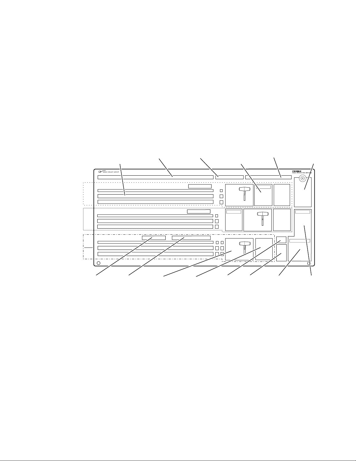
Main Panel
8126_00_01_r0
PVW/AUX Bus
E-MEM
Subpanels (3)
M/E
1
Master E-MEM
Subpanel
Transition
Subpanels (3)
Preview
Subpanel
Transform
Subpanel
M/E
2
M/E
3
PGM
PST
Keyframe Edit
Subpanel
Key Bus
Delegation (3)
Fade to Black
Subpanel
Keyer
Subpanels (3)
DSK
Subpanel
Source Selection
Key, M/E A/B, and PGM/PST
PVW/AUX Re-entries
Aux Bus Delegation
The panel is organized into subpanels that contain groups of related controls (Figure 2).
The 3-M/E Main panel provides real time button, knob, and lever arm
control of three full function mix/effects (PGM/PST with full M/E capability). The panel is identical to the 2.5-M/E panel except for keyer and
wipe functionality in the PGM/PST rows.
The 2.5-M/E Main panel provides real time button, knob, and lever arm
control of two full function mix/effects and one PGM/PST with three
simple Downstream Keyers (DSKs).
Figure 2. Zodiak Main Panel (2.5 and 3 M/E)
System Components
Connectors to the Zodiak Video Processor frame and to other components
of the Zodiak Control Surface are located on the rear of the Main panel. The
Main panel provides power to the separate Menu panel.
Zodiak User Manual 21
Page 22

Section 1 — System Overview
The Main panel power switches, fuses, reset buttons, and floppy drive are
accessed by lifting the top of the Main panel (Figure 3).
Figure 3. Main Panel Inside View
Crosspoint Switch Board
Main Power Supply
M/E Switch Board
Control Panel
Processor Board
5
6
4
7
3
2
9
1
0
Master Reset ButtonBoot Dial Switch (0)
8
Menu Reset Button
RT Panel Reset Button
Floppy Disk Drive
(Main Panel Reset)
Redundant Power Supply
8096_00_07_r3
22 Zodiak User Manual
Page 23

Menu Panel
8096_00_03_r2
Fan
CD-ROM
The Menu panel provides access to additional system controls that generally do not require real time adjustment. The panel includes a touch screen
display, control processor, five knobs for adjusting parameter values, builtin cooling fan, and a CD-ROM (Figure 4 on page 23).
The Menu panel can be installed behind, above, or to either side of the Main
panel, and should be oriented so the screen directly faces the operator. The
Menu panel can be mounted using the standard adjustable console
mounting bracket or an optional flush mount kit that allows for rack
mounting or mounting into a console cutout.
Figure 4. Menu Panel, Front View
System Components
Panel Options
Remote Aux Panels
Connectors to the Zodiak Main panel, Video Processor frame, an external
Zip drive, and other devices are located on the bottom of the Menu panel.
Remote Aux panels provide control of selected Zodiak Aux buses from a
remote location. Three 24-Crosspoint and two 32-Crosspoint Remote Aux
panel types are available for Zodiak systems. Any combination of these aux
panels can be used in a Zodiak system. See
Zodiak Installation and Service Manual
for additional information.
Section 2 – Installation
of the
Zodiak User Manual 23
Page 24
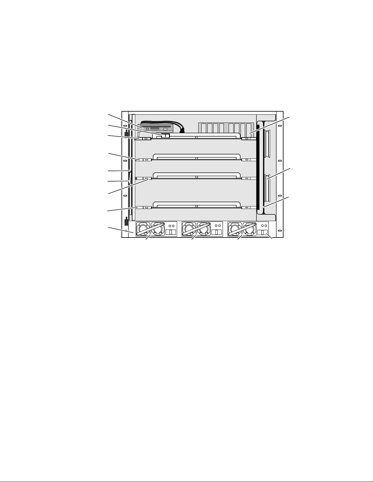
Section 1 — System Overview
Video Processor Frame
The Zodiak Video Processor frame houses most of the system electronics,
with horizontal slots that hold individual system control, video routing,
and signal processing modules. A built-in fan system allows cooling of the
frame. A fully loaded 3-M/E system is shown in Figure 5.
Figure 5. Fully Equipped Zodiak Video Processor Frame Front View (Door Removed)
Floppy Drive
Power Switch
Control Processor/DSK/Still Store
(Slot 1)
M/E (M/E 1 & 2)
(Slot 2)
Air Filter
Air Filter Handle
M/E (M/E 3)
(Slot 3)
Input/Crosspoint/Sync Generator
(Slot 4)
Power Supply Slots (3)
Single Board
Computer
OFF
ON
P/S Slot 2P/S Slot 1 P/S Slot 3
P/S Latch
Mezzanine
Fan (4)
on Module
Fan Module
8096_00_16_r2
The Zodiak system has been designed for easy maintenance. Modules and
power supplies can be removed and replaced safely from the front of the
frame with the power on, simplifying troubleshooting to the module level.
The standard 2.5-M/E Zodiak Processor frame includes the following:
• Floppy disk drive,
•Control Processor/Still Store/DSK module,
•M/E module (M/E 1 and M/E 2),
• Input/Crosspoint/Sync Generator module,
•Two Video Processor frame power supplies, and
•Air filter and Fan module.
The standard 3-M/E Zodiak Processor frame includes the same modules as
the 2.5-M/E system in addition to the following:
•M/E module (M/E 3), and
•Redundant power supply.
The rear of the Zodiak Processor frame provides the reference, video and
system control connectors for the system.
24 Zodiak User Manual
Page 25

Video Processor Power Supply
The Zodiak Video Processor frame houses up to three slide-in modules
rated at 400 watts each. (Figure 5 on page 24). Two hot-swappable power
supply modules (primary and redundant) are standard with the 2.5-M/E
system, and three power supply modules are standard with the 3-M/E
system.
The power supplies load share such that a supply can fail and the Video
Processor frame will continue to operate on the other supply/supplies.
It is recommended that each module’s AC input be connected to a separate
AC supply circuit. Any module(s) for which a separate supply circuit is not
available can be connected to an uninterrupted power supply (UPS).
Video Processor Frame Options
Transform Engine Option
System Components
The Zodiak Transform Engine option available per keyer provides the following internal DPM capability:
• 2-D effects in 3-D space with perspective,
• Page turn,
• Border, outline, and extrude effects,
• Independent drop shadow,
•Glow and defocus effects, and
•Output recursive effects (such as star trails and montage).
RGB Color Correction
In addition to the standard solarization, posterization, mosaic capabilities
and YUV color correction, RGB color correction can be added to all M/E
buses (background, keyer, and utility).
Chroma Keyers
In addition to the two standard chroma keyers, two optional floating
chroma keyers may be added to the system via software.
Zodiak User Manual 25
Page 26
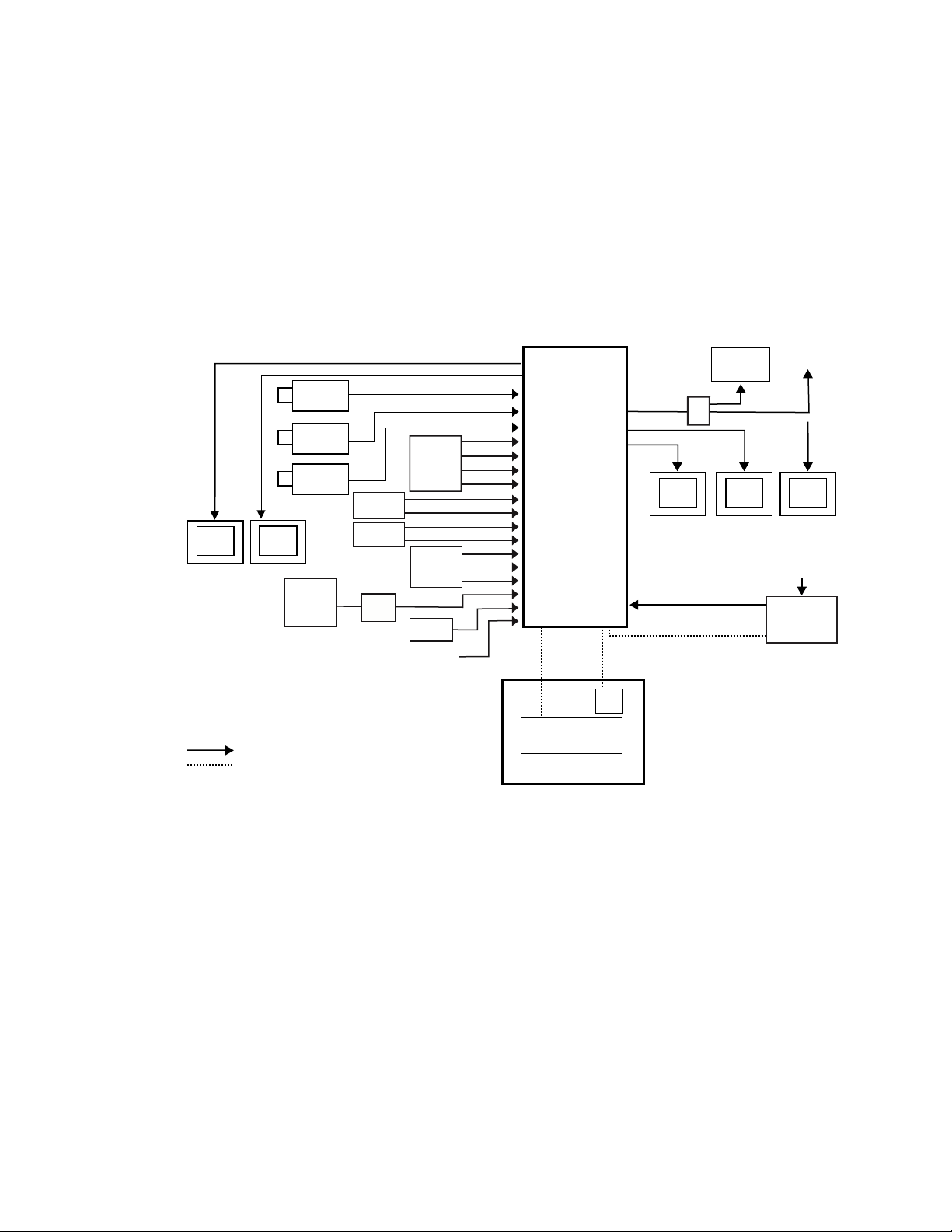
Section 1 — System Overview
Zodiak Facility Example
A basic facility configuration example of a Zodiak system is shown in
Figure 6. Numerous types of sources can be fed to the Video Processor
frame. Each M/E, Keyer and Utility bus has internal video processing
capability to correct color (including optional RGB color correction) and
add effects. In addition to the optional internal Transform Engine capabilities available on each keyer, this facility also utilizes an external DPM
system configured for Effects Send.
Figure 6. Basic Facility Configuration Example
Cam 1
Cam 2
Cam 3
Character
Generator
Paint
System
Monitor
Monitor
Analog
VTR
8900
Series
Profile
VDR
Video/Key
Router
TSG
Reference Black
Aux Bus Outputs
Video/Key
Zodiak
Video
Processor
Frame
Panel LAN
Program Out
Video/Key (Effects Send)
Synchronous Serial (CPL)
Menu LAN
Menu
Panel
VTR
DA
Preview
Monitor
Video/Key (Effects Return)
Other
Monitors
Master Control/
Transmitter
Program
Monitor
1
DPM
Video or Key Signal
Control Line
1
CPL Compatible DPMs: Krystal, GVeous/Dveous
Main Panel
Zodiak Control
Zodiak Main Control Surface
26 Zodiak User Manual
8096_00_18_r4
Page 27

Functional Overview
Video Signal Flow
The basic system architecture (Figure 7) of the Zodiak system has been
designed for operational flexibility. For example, all the outputs from every
M/E and the PGM/PST are routed back to the video crosspoint matrix,
making all these signals accessible to the entire system.
The 2.5-M/E system has two full M/Es and a PGM/PST with DSK. The
3-M/E system has three full M/Es in addition to three simple DSKs and the
ability to link DSK keys to any M/E.
The 64 video inputs to the Video Processor frame can be mapped to any of
the 46 crosspoint buttons (23 unshifted and 23 shifted sources). Internallygenerated black and two backgrounds are also available sources, as are the
four Still Store outputs. This source-to-button mapping is done through a
touch screen menu and can be stored as a user profile for any number of
individual users. Button mapping is the same on all buses.
Functional Overview
The selected video on each bus is deserialized and reclocked before
entering the video processing circuitry. Video processing is available for
each separate M/E background, Key, and Utility bus, providing built-in
solarization, posterization and mosaic effects. In addition, contrast, brightness, and hue can be adjusted on a bus-by-bus basis.
Each full M/E has four full-function keyers with optional internal Transform Engine effects. Each keyer has access to its own simple wipe generator
as well as a pair of standard floating chroma keyers which may be assigned
to any keyers in the system. Two complex wipe generator serve each M/E,
providing a wide range of wipe choices with modulation, rotation and
multiplication of each one. Wipe signals can also be taken from the Utility
bus on each M/E.
The outputs from each M/E Program and Preview are fed to dedicated
BNCs and sent back to the crosspoint circuitry for reentry selection in the
other M/Es. Either Program/Preset output can be programmed as a clean
feed output or with any combination of DSK 1, 2 and 3 keyers active.
Nine Aux buses are available in the 2.5-M/E system; thirteen in the 3-M/E
system. The Aux bus outputs can be utilized in a number of ways,
including configuration as Effects Send pairs for interfacing to external
digital effects systems.
Zodiak User Manual 27
Page 28

Section 1 — System Overview
Figure 7. Simplified Video Flow Diagram — Top Half
Video or Key Signals
Deserializer and Reclock
Serializer
Delay1
Input/Xpt/
Sync Gen
1 – 64
Xpts
M/E 1 Inputs
Key 1 Video
Key 1 Key
Key 2 Video
Key 2 Key
Key 3 Video
Key 3 Key
Key 4 Video
Key 4 Key
A Video
B Video
Utility Video
M/E 2 Inputs
Key 1 Video
Key 1 Key
Key 2 Video
Key 2 Key
Key 3 Video
Key 3 Key
Key 4 Video
Key 4 Key
A Video
B Video
Utility Video
Dual Mix Effect
11
Key Wipe Gen
4 Simple
Complex
Wipe Gen
Video
Processor
Video
Processor
Key 1 Video
Key 1 Key
Key 2 Video
Key 2 Key
Key 3 Video
Key 3 Key
Key 4 Video
Key 4 Key
A Video
B Video
Utility Video
Key 1 Video
Key 1 Key
Key 2 Video
Key 2 Key
Key 3 Video
Key 3 Key
Key 4 Video
Key 4 Key
A Video
B Video
Utility Video
Transform
Engines
Transform
Engines
Key 1 Video
Key 1 Key
Key 2 Video
Key 2 Key
Key 3 Video
Key 3 Key
Key 4 Video
Key 4 Key
Key 1 Video
Key 1 Key
Key 2 Video
Key 2 Key
Key 3 Video
Key 3 Key
Key 4 Video
Key 4 Key
Mixer
Program
Preview
Program
Preview
M/E 1 Outputs
Program
Preview
M/E 2 Outputs
Program
Preview
Aux/Return 6
Aux/Return 7
Aux/Return 8
Aux/Return 9
M/E 1 PGM
M/E 1 PVW
M/E 2 PGM
M/E 2 PVW
Key Wipe Gen
4 Simple
Complex
Wipe Gen
Aux/Send 6
Aux/Send 7
Aux Send 8
Aux/Send 9
8126_00_01_r0
28 Zodiak User Manual
Page 29
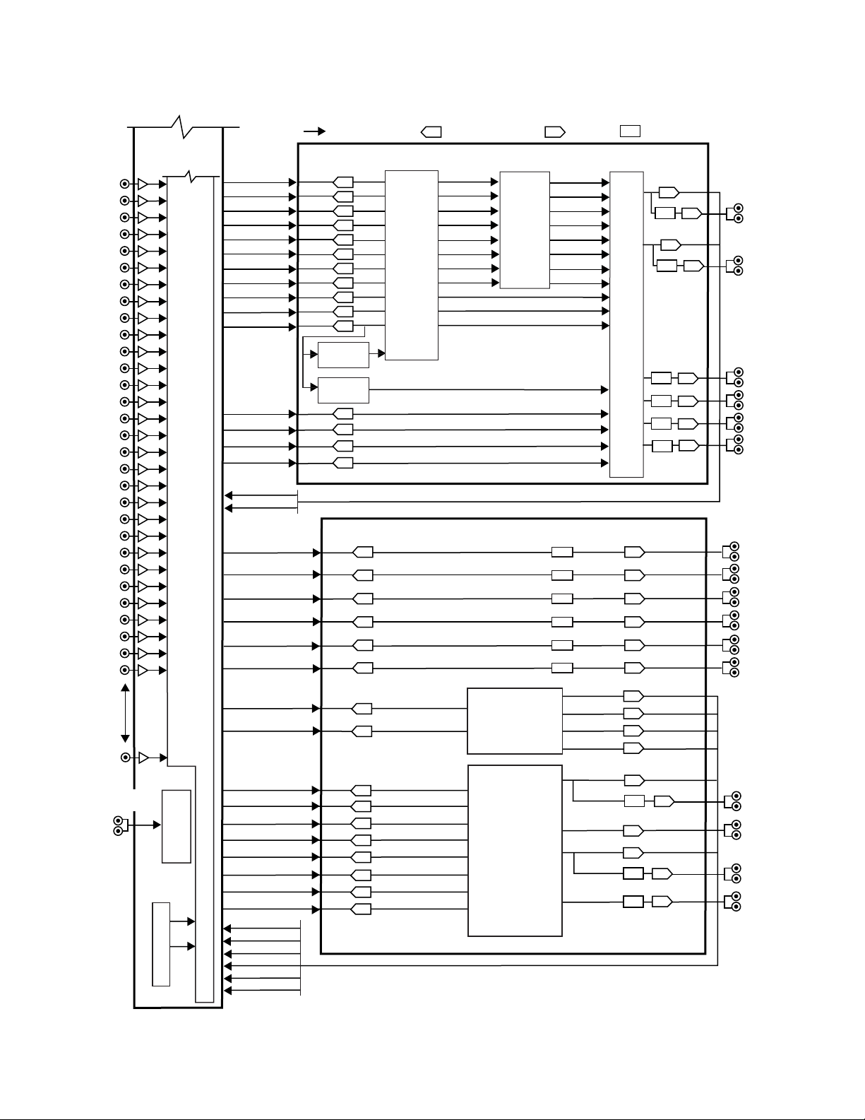
Figure 8. Simplified Video Flow Diagram — Bottom Half
Control Processor DSK
Input/Xpt/
Sync Gen
Deserializer and Reclock
Serializer
Delay
Video or Key Signals
Program A
Program A
Aux 1
Aux 1
Aux 2
Aux 2
Aux 3
Aux 3
Aux 4
Aux 4
Aux 5
Aux 5
Switched PVW
Stillstore 1
Key 1 Video
Key 1 Key
Key 2 Video
Key 2 Key
Key 3 Video
Key 3 Key
A Video
B Video
Stillstore 1
Stillstore 2
Stillstore 3
Stillstore 4
Stillstore 2
Switched
Preview
Still Store
Preview A
Preview B
Program B
Program B
Stillstore 1
Background
Generator
Sync
Generator
Stillstore 2
Stillstore 3
Stillstore 4
Program A
Program B
PGM/PST
DSK Mixer
Bkg 1
Bkg 2
Single Mix Effect (3-M/E Switchers only)
M/E 3 Outputs
M/E 3 Inputs
Key 1 Video
Key 1 Key
Key 2 Video
Key 2 Key
Key 3 Video
Key 3 Key
Key 4 Video
Key 4 Key
A Video
B Video
Utility Video
Key 1 Video
Key 1 Key
Key 2 Video
Key 2 Key
Key 3 Video
Key 3 Key
Key 4 Video
Key 4 Key
Key 1 Video
Key 1 Key
Key 2 Video
Key 2 Key
Key 3 Video
Key 3 Key
Key 4 Video
Key 4 Key
A Video
B Video
Utility Video
Video
Processor
Transform
Engines
Mixer
Key Wipe Gen
4 Simple
Complex
Wipe Gen
Program
Program
Preview
Preview
Aux/Send 10
Aux/Send 11
Aux Send 12
Aux/Send 13
M/E 3 PGM
Aux/Return 10
Aux/Return 11
Aux/Return 12
Aux/Return 13
M/E 3 PVW
Analog 525/625
Reference Input
Xpts
1 – 64
8126_00_03r0
Functional Overview
Zodiak User Manual 29
Page 30

Section 1 — System Overview
System Control
Zodiak system control is designed for flexibility and simplicity. Ethernet,
serial, parallel, and USB are used for system component interconnections.
Tally and GPI control are available. Windows 2000 drives the Menu panel
touch screen. An overview of Zodiak system control is shown in Figure 9.
Figure 9. Zodiak System Control
Main Control Surface
Menu LAN
Tally (Relay)
8 GPI In
8 GPI Out
4 Serial
2 CPL
Panel LAN
Video Processor Frame
Floppy
Drive
Control
System
Hard
Drive
Menu Panel
System Processor
Button Knob Control (Serial)
Touch Screen Control (Serial)
Zip Drive
Optional Keyboard
Optional Mouse
USB
Serial
CD-ROM
Main Panel
Control Panel Processor
Floppy
Drive
Control Line
Control Surface Boundary
NOTE: Main Panel, Menu LAN, Panel LAN 10Base-T or 100Base-T Ethernnet
Point to Point Serial
RS-422/Serial Async
4 GPI In
4 GPI Out
Optional
Future Satellite
Panels (1-2)
8096_00_19_r3
30 Zodiak User Manual
Page 31

Concepts
Introduction
Section 2
In general, any video switcher receives multiple video inputs, performs
signal processing on selected input signals, and then outputs the processed
video. Efficient real time switcher operation is essential for live production,
and can save valuable time in post production environments as well.
Several innovative concepts are employed in the Zodiak Digital Production
Switcher to enhance its operational speed and flexibility. Understanding
these concepts, as well as basic switcher fundamentals, will help you take
full advantage of the exceptional power of the Zodiak system.
Zodiak System Configuration Overview
The Zodiak Digital Production Switcher is designed for operational flexibility, and can be configured to fit various applications. Different Zodiak
systems can have different capabilities, or the same Zodiak system can be
re-configured to have different capabilities at different times.
The way a Zodiak Digital Production Switcher is wired into your facility
affects the Zodiak system’s capabilities. For example, the number and
types of sources physically connected to the system obviously determines
what video the system can handle. However, because Zodiak system
video/key inputs and Aux Bus outputs can be configured, once video
cables are physically connected they need not be moved. Configuration settings also control many other capabilities that affect Zodiak system
behavior.
Zodiak User Manual 31
Page 32

Section 2 — Concepts
Engineering Setups
Zodiak Digital Production Switcher configuration information is divided
into three areas, to simplify and increase the speed of reconfiguring the
system. The basic areas of Zodiak configuration are:
• Engineering Setups (settings established by the engineer in charge that
affect the entire system, which never need to be changed by operators),
• Suite Preferences (settings for a suite that affect all the operators
working in that suite, that are designed to suit a particular show or production style and ensure a consistent working environment), and
•User Preferences (settings that give the operator the ability to customize his individual work surface to meet his personal preferences).
All Zodiak configuration settings are non-volatile. Disk save and load
operations are available that allow users to store configuration information
on removable media for easy transport and for use as backup copies.
Engineering Setups control how the Zodiak Digital Production Switcher’s
major components behave and interact, and how the Zodiak system interacts with the rest of the facility.
Engineering Setups are not likely to change on a daily basis and so are
grouped separately from the Suite and User Preferences. Facility maintenance personnel or the engineer in charge of a production truck generally
manages Engineering Setups. These parameters are usually set during
installation.
Engineering Setups information includes:
•Networking (IP addresses),
• Source definition (described later in this section),
• External device interfaces (DDRs, VTRs, DPM, Router, etc.),
•Control surface and suite definitions (identifying the operating panels
present and their relationships to one another), and
•Various other system functions.
32 Zodiak User Manual
Page 33

Suite Preferences
Suite Preferences define how the control surfaces associated with a Zodiak
suite behave. Suite Preferences can substantially change system behavior,
not just a user’s view of the system. Suite Preferences are intended for dayto-day or session-to-session changes in Zodiak system operating behavior
and so are open for modification by operators.
Suite Preferences include:
•Preview preferences,
• Safe title, preview behavior, etc.,
•Video specifications (525/60, 625/50, aspect ratio, etc.),
•Default Source Memory (initial keying and video processing settings
•Default Keyframe (initial settings for many other user controls), and
•Various other suite functions.
Zodiak System Configuration Overview
used for each source on each bus),
User Preferences
User Preferences allow users to customize a Zodiak control surface to suit
their personal operational style. User Preferences do not change Zodiak
system capabilities.
User Preferences include:
• Source to button mapping (described later in this section),
•Aux Bus delegation mapping,
•Clip control preferences
• Shift preferences, and
•Various other user functions.
Zodiak User Manual 33
Page 34

Section 2 — Concepts
Signal Routing
Inputs and Sources
Incoming video signals are connected to the Zodiak system via BNC connectors on the rear of the Zodiak Digital Processor frame. All inputs are
serial digital (SMPTE 259M, CCIR 601). Signals from external devices not
operating in this standard will need to be converted.
Some devices (for example, a camera providing serial digital output) may
provide a video signal that can be received on a single connector. However,
other devices may output multiple signals.
For example, a character generator usually provides a signal with two components (commonly called video and key). Some incoming signals may also
originate from devices the Zodiak system can control (Router, DPM, DDR).
For a Zodiak Digital Production Switcher, the term source refers to all the
video signals and other attributes associated with a device. This is a fundamental concept. The Zodiak system is based on sources, not input signals
or crosspoints. Each source can be given a descriptive name, but has an ID
number for absolute identification. The Zodiak system uses ID numbers,
not source names or input connectors, to identify each source. Defining
each source is an important aspect of the Zodiak system.
Source Definition
When the Zodiak system is first configured, all sources are defined so the
incoming signals from each device can be used effectively. This is usually
done by engineering personnel, not operators, and once set these definitions are not changed.
A source definition data file tells the system how many signals a source has
(video only, or video and key), which physical input(s) to route whenever
a particular source is selected, the default processing of the source’s key
signal (if present), and what external devices (if any) are associated with
that source. Tally is another important attribute of a source. On-air tally
relays are related to sources, not physical inputs or source select buttons.
The source definition process includes assigning a name to each source.
Once sources are defined, the user is able to select the source by name, and
the Zodiak system automatically manages all the necessary signals, performs any default processing, and enables any additional control capabilities associated with that source.
34 Zodiak User Manual
Page 35

Source definition data is stored as a part of Engineering Setups. Only one
set of source definition data can be active on a Zodiak system at a time.
Note that source definition is separate from source memory, which specifies what processing is to be applied to the source and can dynamically
change during system operation.
Source to Button Mapping
Source to button mapping makes it possible to organize sources on Zodiak
control panels in a preferred order. For example, cameras can be placed on
the left side or the right side of the button row, whichever is preferred.
Source mapping is distinct from source definition, as source mapping only
involves the location of sources on the control panel and does not affect any
capabilities defined for the sources. Note that E-MEM effects store the
source IDs, not the source select buttons, so remapping sources will not
change the appearance of recalled effects.
Source Memory
Signal Routing
Keying and other parameters can be saved to a separate source memory for
every Zodiak system source. These parameters can be applied automatically whenever that source is selected. See Source Memory on page 72 for
specific information.
Buses and Crosspoints
A bus is technically defined as a signal path where one of several available
inputs can be selected to feed a single output. A crosspoint is an electronic
switch that allows a signal to pass when the switch is closed. On video
switchers, a bus can be constructed containing a series of crosspoints,
which permits selecting which one of several incoming signals will be sent
out the bus. In Figure 10, source 2 has been selected on the background A
bus. This signal can now be called background video is available for further
processing.
Figure 10. Buses with Crosspoints
Source Signal Inputs
12345
Crosspoint
Switch
Background A Bus
Signals Continue to Other Buses
Zodiak User Manual 35
061_00_20
Page 36

Section 2 — Concepts
Buttons on a control panel can be used to control the switching of crosspoints. The buttons are usually arranged horizontally, making it easy to
imagine the available signals coming in from the top, and the single bus
output signal going out the right side.
In earlier generation switchers, the terms crosspoint button and crosspoint bus
have been used in reference to control panel source selection. For a Zodiak
system, the terms source button and source bus will be used. These terms
better reflect a system operating philosophy that is source rather than crosspoint based. The Zodiak system does not directly associate a source select
button with a physical crosspoint. The association goes first through source
to button mapping, then through source definition to find the physical
inputs.
On the Zodiak system, a single source button can control crosspoints on
different buses simultaneously. For example, during keying on an M/E,
both the video and key signals of a source can be selected with a single
button press. In this case two different crosspoints on separate buses (key
fill bus and key cut bus) are actually switched when the button is pressed.
In the upper part of Figure 11, the video component of source 2 in the figure
has been selected on the key fill bus and becomes the key fill signal for subsequent keying. The key component of source 2 selected on the key cut bus
becomes the key cut signal for keying. The lower part of Figure 11 shows
how the same source (source 4) can be selected for both the key fill and key
cut signals.
Figure 11. Multiple Crosspoint Control
Source Signal Inputs
123 45
Key
1 3 4 5
Single Button Controls Both Crosspoints
1 3 4 5
Key Video Key Video Video Only Video OnlyVideo
2
2
Single Button Sends Same Signal to Both Buses
Key 1 Fill Bus
Key 1 Cut Bus
Key 2 Fill Bus
Key 2 Cut Bus
0618_00_21_r1
36 Zodiak User Manual
Page 37

Shifted Sources
An operator may need to quickly access many sources during a production.
However, a control panel has size limitations, since all the source selection
buttons must remain within reach. The Zodiak system provides shifted
buttons to allow access to more input sources from the control panel.
On a 2.5- or 3-M/E Zodiak system, up to 46 sources can be mapped at one
time, 23 to the unshifted source selection, and 23 to the shifted buttons. A
dedicated
(Crosspoint 24) for every bus. Two shift modes are available: Normal and
Latched.
In Normal mode, shifted or unshifted status of the bus is indicated by the
state of the
a source button always selects the shifted source for that bus. The
button will light when the row of buttons to its left are shifted.
Signal Routing
Shift button is provided as the farthest right crosspoint button
Shift button light. Holding down the Shift button while pressing
Shift
In Latched mode, the
the Caps Lock button on a standard keyboard. When on, it lights to indicate
that the subsequent selection(s) on the crosspoint selector row will be made
from the shifted set of sources (24 through 46). When off, the subsequent
selection(s) come from the unshifted set (1 through 23). If the user toggles
the
rently selected input, then the crosspoint selector button blinks to indicate
an Out of Sync condition.
A useful configuration is to have sources normally used for backgrounds
(e.g. VTRs) mapped to unshifted buttons, and sources normally used as
keys (e.g. character generators) mapped to shifted buttons. Then you can
then set all the background buses to an unshifted preference, and all the
key buses to a shifted preference. All normal source selections can then be
made without having to use the shift modifier buttons.
Mix/Effects (M/E)
An M/E is a subsystem of a video production switcher that can create a
composite of two or more pictures. An M/E includes multiple source selection buses and provides transition (mix and wipe) and keying capabilities
on the selected signals. An M/E can be organized with the keying circuitry
separate from the mixing circuitry, which permits Effect Send capabilities
(see Effects Send on page 39 for more information).
Shift button toggles on and off in a manner similar to
Shift button to the state that is opposite from the shift state for the cur-
A simple basic M/E used in a typical switcher will be used as an example
in the following discussion. A Zodiak M/E has added capabilities, but the
basic principles described here will apply. See Figure 7 on page 28 for a
simplified diagram of the actual Zodiak M/E architecture.
Zodiak User Manual 37
Page 38

Section 2 — Concepts
Figure 12. Simplified Mix Effects (M/E) Subsystem
Source Signal Inputs
Crosspoint
Matrix
Key Fill
Key Cut
Background A
Background B
Keyer
Wipe
Generator
Mixer
M/E
Outputs
M/E Program
M/E Preview
061_00_22_r1
The basic M/E shown in Figure 12 has an A and a B background bus. These
buses select the background video signals sent to the output of the M/E.
Generally the source on the background A bus is the current background
output, and the source on the background B bus is the background video
that will be used next. During most transitions, portions of both backgrounds are output simultaneously. The keyers in the M/E allow the inclusion of additional material over the background. Wipe generators also
exist, which create patterns used by the mixer for wipe transitions, or used
by the keyers to modify the signals it sends the mixer. See Transitions on
page 42 and Keying on page 46 for more information. The processed signal
in an M/E is then sent to an M/E output, typically program or preview.
A video production switcher can have more than one M/E. For example, a
3-M/E Zodiak system has three (M/E 1, M/E 2, and M/E 3). Each Zodiak
M/E produces two outputs, M/E Program and Preview.
Re-Entry
Switchers with multiple M/Es generally have re-entry capabilities. Reentry permits the switcher to select the output of one M/E for use as an
input source to another M/E. The signals are routed internally.
The Zodiak system supports M/E re-entry. For example, an output of
M/E 1 can be sent to M/E 2 or M/E 3 (PGM/PST), and an output of M/E 2
can be sent to M/E 1 or M/E 3 (PGM/PST).
Alternate Buses and Delegation
Many earlier generation switchers had M/Es equipped with two keyers,
and each M/E could accept two background sources. This permitted
mixing or wiping between two backgrounds, and keying up to two additional sources over the background. Dedicated rows of control panel
buttons were used to select these key and background signals.
Each Zodiak system M/E actually has four keyers, each handling a fill and
a key signal, and each M/E can accept three background sources (A, B, and
Utility). Providing individual source selection rows for each M/E is
38 Zodiak User Manual
Page 39

Utility Buses
Effects Send
Signal Routing
impractical, as the panel would become too large for an operator to reach
all the buses. For ease of use, Zodiak panels have alternate buses accessed
by delegation, using Key and PVW/AUX delegation subpanels.
Besides the standard A and B background inputs, each Zodiak M/E also
accepts Utility inputs. The Utility bus can be used to select signals for
special purposes, and has no relation to the background buses. For
example, a video signal selected on the Utility bus can be used to feed a
custom pattern into a wipe generator, or create a custom border wash pattern.
Effects Send provides a method of integrating digital effects devices into an
M/E subsystem. Effects Send switches the key cut and key fill outputs of
the keyer of an M/E to a digital effects device for manipulation. The manipulated key cut and key fill outputs are then received and sent directly to the
inputs of the mixer circuits of the M/E. Effects Send allows you to process
a key effect as though the digital effects circuits were located inside the
M/E itself.
On the Zodiak system, Effects Send is integrated into each M/E and is an
extension of the keying control system (Figure 13).
Figure 13. Effects Send Diagram
Digital
Source Signal Inputs
Source
Selection
Buses
Keyer
M/E
Effects
System
Mixer
M/E
Outputs
0618_00_24
The Zodiak system supports external Effects Send. External Effects Send
routes the key fill and key cut output signals from an M/E keyer to a separate, external digital effects system, like a Krystal DPM. The signals are
manipulated by the external device and then sent directly back to that
M/E’s mixer inputs. If the Zodiak system is equipped with the optional
Transform Engine option, the effects become part of the internal M/E’s
mixer.
Zodiak User Manual 39
Page 40

Section 2 — Concepts
Outputs
M/E, Program and Preview Output Buses
Video production switchers generate several different video outputs (Program, Preview, etc.). A final program output from PGM is typically sent to
the transmitter for broadcast and/or to output devices for recording. Individual M/E program and preview outputs and an additional switched
preview output are sent to monitors in the control room. These outputs
may also be routed elsewhere in the facility. Aux Bus outputs may also be
used for special purposes.
The Zodiak system has dedicated BNC output connectors for the following
signals:
•M/E 1 PGM and PVW,
•M/E 2 PGM and PVW,
•M/E 3 PGM and PVW (3-M/E systems only),
•Program A and B (with configurable clean feed),
Aux Buses
•Preview A and B, and
•Switched Preview, selectable on the control panel from PVW PRI, ME 1,
ME 2, ME 3 (3-M/E system only), PGM A or PGM B.
Video production switcher Aux Buses can be used to select and route
sources to specific destinations. For example, a source selected on an Aux
bus can be sent to an ISO recorder for instant replay. This can be done
directly by the Technical Director while she switches the program.
Remote Aux panels can be used to give different operators control over one
or more Aux buses. It is also possible to assign control of an Aux bus to an
external device, like a DPM, and allow that device to directly switch
sources as required.
40 Zodiak User Manual
Page 41

Resource Sharing and Point Of Use
The Zodiak system can share some resources for use at different locations.
The location where a resource is being used is called a point of use. Different
types of resources are shared differently.
Floating resources (like Chroma Keyers) move between points of use, and
the parameters controlling these resources are considered part of the point
of use. These resources are used at only one point of use at a time. When
the resource floats to the new location, its behavior changes. For example,
A Chroma Keyer set for specific parameters in M/E 1 Key 1 can be assigned
to another keyer and have different settings applied.
Other Zodiak system resources behave differently. For example, wipe
pattern generator resources can be used for an M/E wipe transition, as a
preset pattern, as a mask, or at other points of use. It is also possible to
assign the output of the same wipe pattern generator to different points of
use at the same time.
For efficient operation, the Zodiak system has divided the parameters controlling wipe pattern generators and related utility bus functions into two
categories; shared generator parameters and point of use parameters. The set of
parameters for the shared generator are used by all points of use, so
changing one of these parameters will affect all locations where that wipe
pattern generator is being used at that time. Separate sets of point of use
parameters, however, are maintained for each Zodiak system point of use
(same as Chroma Keyers described above). These settings are used only by
each individual points of use, so changing them will not affect any other
point of use.
Resource Sharing and Point Of Use
For example, a wipe shape (box, circle, etc.) is a generator parameter, but
the softness of the shape’s edges is a point of use parameter. If the same
wipe generator is used by both an M/E wipe transition and a preset pattern, adjusting softness at one point of use will not affect the other’s softness settings. However, changing the pattern shape affects both locations.
Zodiak systems differ from the Grass Valley Group Model 4000 switchers
in the division between wipe pattern generator and point of use. In the
4000, the edge is created as part of the generator so all points of use have
the same softness and border width. The Zodiak system duplicates this circuitry allowing each point of use to have a different edge on the same basic
wipe pattern shape.
Zodiak User Manual 41
Page 42

Section 2 — Concepts
Transitions
Cut
A transition is a change from one image to another. The Zodiak system supports four (three basic and one optional) types of transitions:
•Cut
•Mix
•Wipe
• DVE (optional)
A transition can be applied to the entire picture, or to only the background
or keyed elements of the picture, and can include multiple elements.
A cut is an instantaneous switch from one image to another (between suc-
cessive video fields or frames). The simplest type is a hot cut, accomplished
by selecting a different source on a bus feeding an M/E output. This only
changes that bus’s contribution to the output, and does not change what
elements may be involved in the output (the same buses are involved).
Mix
The Zodiak system also provides cut transitions, where the elements
involved in a composite can be changed instantaneously. Different buses
can be included or excluded, causing changes in the resulting composite
image. Background cut transitions on an M/E are first selected on the Background B bus to allow previewing the upcoming picture before it is cut onair.
A mix is a transition from one picture to another where the new picture
fades in as the existing picture fades out. During a standard mix transition
a superimposition of both pictures, each at a lower intensity, is visible.
The Zodiak system allows mixing from one background to another and to
mix up to four separate keys on or off over a background. Background and
key mixes can be done separately or simultaneously.
Full Additive Mix
Full Additive Mix (FAM) is a special mix transition that the Zodiak system
supports besides normal crossfade transitions. Picture elements in FAM
transitions are composited differently through the time of the
transition(Figure 14).
42 Zodiak User Manual
Page 43

Figure 14. Normal and FAM Mixes
Transitions
Wipe
Current
Picture
Picture
Picture
Intensity
Start End
Crossfade
Transition
Next
Midpoint
Start End
Current
Picture
Next
Picture
FAM
Transition
Midpoint
8126_00_24_r0
FAM transitions first fade a new picture to full intensity and then fade the
old picture out, but both full intensity pictures are mixed together to the
output during the transition. The resulting signal is clipped at white level
to prevent generating illegal video.
A wipe is a transition from one picture to another in which the edge of a
shape moves across the screen, revealing the new picture. Wipe transitions
can be applied to backgrounds, to keys, or to both simultaneously. A wipe
transition shape can be selected from a variety of patterns, and these patterns can be adjusted in several ways (position, aspect ratios, edge
attributes, etc.).
Other Wipe Pattern Generator Uses
Preset Black
Each Zodiak M/E has two separate wipe systems, each of which can be
assigned a different wipe pattern and be adjusted independently. These
systems can each use one of the two available complex wipe pattern generators with advanced capabilities. It is also possible to combine these wipes
to create extremely complicated wipe transition shapes, and generally this
is used only by advanced operators. Utility bus video signals can also be
used to generate a custom pattern for a wipe transition or other purposes.
Wipe pattern generator circuitry can be used for purposes that do not
involve transitions. Each Zodiak M/E has the two complex wipe pattern
generators described above, and each of its four Keyers also has a simple
pattern generator and a box pattern generator, making a total of six. These
pattern generators can also be used for Preset Pattern, Masking, and Matte
Washes.
Preset Black is a special type of transition, where the picture transitions to
black, and then transitions out of black to the new picture. Preset Black is
really two transitions, one to and one from black, and so requires two oper-
Zodiak User Manual 43
Page 44

Section 2 — Concepts
Fade to Black
Transition Rate
ator commands to complete. Preset Black can be used with any transition
type (cut, mix, or wipe). The entire picture goes to black, even if all the transition elements involved in the picture were not selected.
The Fade to Black control in the DSK allows the Program output of the
switcher to be brought down to black at a predetermined transition rate.
Cut transitions are instantaneous, but mix and wipe transitions have durations. Transition durations can be set in advance to a specific transition rate,
and be initiated by pressing a button the control panel. It is also possible to
manually control transitions using a lever arm.
On the Zodiak system, one transition rate can be assigned to the main transition of each M/E. This type of transition can be controlled by that M/E’s
lever arm. Each of the four keyers on each M/E can also be assigned its own
transition rate, initiated with a separate Key Mix button on that M/E.
Flip Flop Background Buses
At the completion of a transition, the background buses swap their source
selections (flip flop). This makes the upper bus always act as the on-air bus,
and the lower bus act as a preset bus. The operator can reliably setup the
next source on the lower bus without disturbing the source selected on the
on-air upper bus.
For example, if a transition begins with source 1 on Background A and goes
to source 2 on Background B, as soon at the transition to source 2 completes,
source 2 will be taken to the Background A bus (without disturbing the
output of that M/E). The source 1 selection will also be immediately taken
to the Background B bus.
Look Ahead Preview
If a preview monitor is configured for Look Ahead Preview mode, the end
result of the upcoming transition can be viewed on that monitor. This lets
the operator know in advance what will occur for that next transition. The
mode you select for each preview monitor depends on the number of monitors available and the individual requirements of the facility.
44 Zodiak User Manual
Page 45

Current and Next Stack
Zodiak uses a current and next stack approach for transitions that involve
multiple elements. The current stack is the current M/E output including
any keys that are on. The next stack is defined by the current stack and
whatever next transition elements have been selected. Look ahead preview
always displays the next stack. Next transition elements affecting stacks are
Keys 1 - 4, background, and key priority.
Zodiak transitions always occur from the current stack to the next stack.
For example, if the current stack has Key 1 over Background A, and the next
stack specifies Key 2 over Background B, a mix transition will occur
between the composites (Key 1 over A to Key 2 over B). This is different
from mixing Key 1 off, Key 2 on, and mixing between A and B at the same
time, which would cause the keys to go transparent over their background
during the transition.
On the Zodiak system, opacity is retained throughout the transition, so
midway through this example Key 1 remains fully keyed over Background
A, and Key 2 is fully keyed over Background B. The transition occurs
between these two fully keyed composites.
Transitions
Key Priority and Transitions
The four keyers on a Zodiak M/E can be assigned priorities. This determines the layering of the keys. The highest priority key appears on top,
while keyers with lower priority may be partially or fully hidden behind
those with higher key priorities. The backgrounds always have the lowest
priority. Changes in key priority can be included as a part of a transition.
Like any other transition, the current stack will transition to the key priority of the next stack. For example, suppose the current stack has Keys 1,
2, and 3 in that key priority order over Background A, and the next stack
specifies key priority order 3, 2, 1. A mix transition will occur between the
1, 2, 3 composite order to the 3, 2, 1 composite order. All three keys will
remain fully keyed over the background, and will mix to their new key priority order.
Zodiak User Manual 45
Page 46

Section 2 — Concepts
Keying
Keying inserts part of one picture into another to create a composite picture. Keying involves three signals:
• Background,
•Key cut, used to specify where to cut a hole in the background, and
•Key fill, used to fill the hole in the background. The fill can be an
incoming video signal or it can be an internally generated matte.
A separate key cut input signal is not necessarily required for keying. For
example, a self key (also called a video key) uses the same input signal for
both key cut and key fill.
The Zodiak system supports the following types of keys:
• Linear Key (fixed and adjustable)
• Luminance Key
•Preset Pattern
•Chroma Key
The Zodiak system also supports self keys and split keys.
Matte Fill Key Example
One of the earliest keying techniques was to use an art card and camera to
perform a luminance key with a matte fill. This type of key is a good
example for explaining basic keying principles because three separate and
independent incoming signals are used.
To insert a green logo into background video, the logo can be printed in
white on black paper and a camera can be focused on it. The signal from the
camera can be selected as the key cut signal and green matte video can be
selected as the key fill signal sent to the keyer. The key cut signal is then
adjusted (clipped) to ignore the black paper and use only the white logo
shape to cut a hole in the background video. The keyer then shapes the key
fill to precisely match the logo-shaped hole cut in the background and fills
46 Zodiak User Manual
Page 47

Keying
it with green matte video. This creates a green logo inserted into the background (Figure 15). Because luminance values of the key cut signal are
used to cut the hole in the background this is called a luminance key.
Figure 15. Matte Fill Luminance Keying Example
Background
Shaping Video
LOGO
Key Cut
Key Fill
In this keying discussion illustrations rather than actual screen images are
used for simplicity, and because the printing process has difficulty capturing the subtleties of soft key edges.
In the matte key example above, the key fill signal was a full raster color
that did not match the shape of the key cut signal. This key fill signal is
accurately called non-shaped video, but may also be referred to as unshaped
video since both signal types are processed identically during keying.
LOGO
Background with Matte Key Inserted
0618_00_32_r1
Some external devices (e.g., character generators) provide a key cut signal
and an already processed companion key fill signal. A key fill signal that
correctly matches the key cut signal is called shaped video. During keying,
properly shaped key fill video can be summed with a background signal
(with a hole cut) and achieve the desired result. When the shaping is performed by the source device, the Zodiak system can use a standard clip and
gain setting defined during system configuration to create the key cut
control signal, and so relieve the operator of having to adjust clip and gain
manually.
If a key fill does not match the hole in the background (like in the matte key
example above), the key fill needs to be shaped by the switcher. By multiplying the key fill signal with the key control signal the unwanted areas of
the fill can be made black, shaping the video to match the hole before it is
Zodiak User Manual 47
Page 48

Section 2 — Concepts
summed with the background. Key fill video must be shaped using the key
cut signal actually used to create the hole in the background. Video shaped
with a different key cut signal will not key correctly.
The Zodiak system, as well as some external devices like DPMs, can also
divide a shaped video signal by its own key signal. The result is called
unshaped video. For optimum image quality, shaping and unshaping operations should be minimized. In general, devices should be installed and
configured in a manner that prevents them from having to unshape
incoming video just to reshape it again afterwards.
Specifying whether source signals are shaped or unshaped is part of the
Zodiak system configuration process (source definition). Properly shaped
video is an important aspect of keying. See Properly and Improperly Shaped
Video on page 58 for more information.
Note that an unshaped signal viewed directly will show harsh edge artifacts due to dividing by a small number. This is normal and expected.
Keying this signal will clean up its appearance.
Key Control Signal Adjustment
During keying, the selected key cut signal can be converted into a key
control signal. It is the key control signal that actually cuts the hole in the
background video. Adjusting the key control signal (Clip and Gain) is
essential in the keying process. The art of setting up a good key is to use just
enough Gain to suppress any imperfections in the incoming key signals.
Setting Gain too high can cause ragged key edges.
The Zodiak system provides two methods for adjusting the key control
signal, Clip and Gain, and Clip Hi and Clip Lo. Note that the same basic
keying process is controlled by either of these methods.
48 Zodiak User Manual
Page 49

Video
y
Retained
Mix of
Background
and Fill Video
Video
Removed
Clip and Gain
The Clip and Gain operation selects a threshold of the selected key cut
video that will be used to cut the hole in the background video. Clip controls the threshold, and Gain controls the softness of the key edges and any
translucent areas. High portions of the key cut signal specifies what video
is retained, and low portions determine what video is removed. Intermediate levels specify a soft blend of the background and fill video
(Figure 16).
Figure 16. Key Clip, Gain, and Key Control Signal
Gain
Clip
Key Cut
Signal
Key Control
Signal
Key Control
Signal
Inverted
(Hole Cutter)
Keying
Background Video
Removd
Background Video
Retained
0618_00_31_r1
Clip
Clip and Gain control is appropriate for high gain keys (see below), to
easily adjust where the relatively hard transition from background to fill
occurs. In this mode, changing the Clip control moves the threshold up and
down without affecting Gain, which is adjusted separately with its own
Gain control.
High Gain, Low Gain, and Unity Gain
A high gain key has a narrow range, creating harder key edges. A low gain
key has a wider range, creating softer key edges. Linear keys typically use
minimal gain (also called unity gain) to completely preserve the soft edges
of the keys (Figure 17). Note that the Zodiak system also supports keys that
go below unity gain.
Figure 17. Keying Gain Values
Gain
Gain
Gain
Clip
Clip
High Gain Low Gain
Unit
Gain
Zodiak User Manual 49
618_00_30_r1
Page 50

Section 2 — Concepts
Clip Hi and Clip Lo
On the Zodiak system, Gain has a percentage value. A Gain value of 50%
requires a luminance change of 50% of the distance between black and
white to produce a keying signal ranging from transparent to opaque. A
gain value of 100% (unity gain) uses the entire range between black and
white for this transparent to opaque transition. A gain value of 0% produces the hard key edges (a high gain key).
The Zodiak system also supports a Clip Hi and Clip Lo mechanism. With
Clip Hi and Clip Lo, two thresholds are established. The upper threshold
specifies at what point video will be completely removed from the background, and the lower threshold determines at what point background
video will be retained completely intact (Figure 18).
Figure 18. Key Hi, Clip Lo vs. Clip and Gain
Clip Hi
Clip Lo
Key Cut
Signal
Clip
Gain
0618_00_29
In this mode, Gain changes when either control is adjusted. The difference
between the upper and lower keying thresholds is equivalent to gain:
Clip Hi = Clip + Gain/2
Clip Lo = Clip – Gain/2
Clip Hi and Lo control is more appropriate for low gain keys, to allow independent control of the two thresholds. For example, when adjusting a
linear key the operator wants to control where the fill becomes opaque
(Clip Hi) and where the fill becomes transparent (Clip Low). In Clip Hi/Lo
mode adjusting the point of opacity does not change the point of transparency, and vice versa.
Clip, Gain, Clip Hi and Clip Low adjustments always interact. Changing
one always results in changes to two other values. Changing Clip Hi or
Clip Low changes both Clip and Gain, not just Gain.
50 Zodiak User Manual
Page 51

S-Shaped Key Signals
On the Zodiak system, an S-shaping function is applied to the edges of
luminance keys. S-shaping smooths the sharp corners of a luminance key
control signal, which helps prevent banding artifacts. S-shaping a signal
minimally affects the key edges, and does not move key thresholds or affect
the overall gain of the key (Figure 19).
Figure 19. S-Shaped Luminance Key Control Signal
Keying
Key Control Signal
S-shaping is generally not applied to linear keys because the external
device usually applies an S-shaping function when it generates the key cut
and key fill signals. S-shaping should not be applied twice.
Additional Keying Controls
The following additional controls are available for keying.
Key Invert
Keys can be inverted, causing holes to be cut in the background where a
normal key retains the background, and vice versa. Key invert makes the
white areas of the key cut signal produce transparency, and the black areas
produce opacity, the opposite of a standard key.
Masking
Masking defines areas that are protected from keying (Inhibit Mask) or
always key (Force Mask). The shape of the mask can originate from a wipe
pattern generator or by a selected mask signal (typically a key fill signal
delivered via one of the Utility buses).
S-Shaped
Key Control Signal
0618_00_33_r1
With the Zodiak Still Store, the mask signal can be a frozen page of video
or a key fill. Complex mask shapes are often easier to draw by hand than to
create with multiple wipe patterns.
Zodiak User Manual 51
Page 52

Section 2 — Concepts
Opacity
Key Positioning
Key Size
The opacity of a key can be adjusted. When opacity is reduced below 100%
some background video is allowed to show through areas where it is normally excluded. Key opacity is an adjustment to the overall intensity of the
key, and is separate from Clip and Gain controls. Note that a common
mistake is to set opacity to zero and forget that adjustment was made,
which can cause confusion later when that key is selected but not visible.
Key positioning allows slight adjustment of the horizontal position of the
key cut signal relative to the key fill signal. This is useful if the timing of the
two signals at the switcher inputs are not matched properly. This is generally only a problem if the cut or fill follow analog paths from source to
switcher or if the source has video/key timing adjustments which have
been set to compensate for other delays within the facility.
Coring
Show Key
Key size allows the key cut signal to be narrowed slightly. This can greatly
enhance self keys and chroma keys that have been reshaped.
Coring helps reduce video noise in Chroma keys. Coring is used when a
key fill signal has noise in areas that are supposed to be transparent. When
noise exists in these areas it can appear in the background portion of the
keyed composite. Coring replaces the noisy black areas outside the shaped
fill with clean black before it is summed, eliminating the noise.
Although the key control signal is not directly visible in the final video
output, this signal can be previewed as a black and white image using the
Show Key function. White areas of a show key indicate areas of complete
opacity, black indicate complete transparency, and gray areas indicate
translucent areas of the key. The whiter the show key signal, the more
opaque the key will be. This key preview signal reflects all the adjustments
that have been made to the key control signal.
Linear Key
A linear key typically uses separate key cut and key fill input signals that
are intended to be used for linear keying. The key cut and key fill are
usually anti-aliased (soft edged) shaped signals created by a character generator or graphics system. There may also be translucent areas intended to
allow some background to show through the key (watermarks). The level
52 Zodiak User Manual
Page 53

Keying
of the key cut signal determines where and how deeply the hole will be cut
into the background. The intended soft edge and translucency of the key
can then be faithfully reproduced (Figure 20).
Figure 20. Linear Keying
LOGO
Background Video
LOGO
Key Cut Key Control
Clip
Gain
LOGO
(typically unchanged)
LOGO
Key Fill
Note The soft edges in the illustrations in this part of the manual are simulated. The
key edges are actually gradients, which allows these edges to blend smoothly
with the background.
Key Hole in Background
x
Invert
+
LOGO
Completed
Linear Key
618_00_61
Fixed and Adjustable Linear Keys
The Zodiak system supports both fixed and adjustable linear keys. A fixed
linear key uses clip and gain values defined in system configuration to
create the key cut signal. Typically these values are Clip 50% and unity
Gain (equivalent to Clip Hi 100%, Clip Lo 0%). Once fixed linear key values
are defined, these sources can be used easily without the operator having
to set up the key every time it is used.
An adjustable linear key provides the operator limited control over Clip
and Gain (or Clip Hi/Lo) values. This lets the operator fine tune the settings if the normal fixed linear values are not producing a good enough key.
Zodiak User Manual 53
Page 54

Section 2 — Concepts
Luminance Key and Self Key
A luminance key uses the luminance of an incoming source to specify
where to cut the hole in the background. The earlier example of a matte fill
key is a type of luminance key. Luminance keying is typically done on
sources that do not have an accompanying key cut signal, like a video
camera. The key cut signal must be generated from the incoming video
signal, using clip and gain controls. When only one source is used for both
key cut and key fill, the key is called a Self key or Video key. The same key
source signal is multiplied by the key cut signal to create the key fill, and
then the signals are summed (Figure 21).
Figure 21. Luminance Keying (Self Key)
Background Video
Key Source
(video only)
Key Hole in Background
x
Invert
Clip
Gain
Key Control
+
Completed
Luminance Key
Key Fill
x
Clip and Gain (or Clip Hi/Lo) controls for luminance keys offer wide
adjustment ranges. On the Zodiak system, an S-shaping function is also
applied to the edges of luminance keys.
0619_00_62
54 Zodiak User Manual
Page 55

Chroma Key
Keying
A chroma key is a key that detects color (rather than luminance) in a video
image and replaces it with a new background. For example, a reporter may
be in a studio sitting in front of a backdrop with a blue or green backing
color, and the new background can be a mountain scene. The completed
chroma key consists the mountain scene replacing the backing color, creating the illusion that the reporter is sitting in front of the mountain
(Figure 22).
Figure 22. Chroma Key (Additive or Multiplicative)
Background Video
Chroma Key Source
(video only)
Backing Colors Selected Key Control
Chroma Key
Primary
Suppression
Chroma Key Fill
Backing Color Suppressed
Invert
Clip
Gain
Chroma Key Fill
Backing Color Removed
x
Multiplicative Chroma Key
Key Hole in Background
x
Invert
+
Completed
Chroma Key
Chroma Key
Secondary
Suppression
Additive Chroma Key
The terms foreground and background are often a source of confusion
when used for chroma keys. Foreground refers to the people or objects in a
chroma key scene that are in front of the colored backdrop. Background
refers to the scene that will replace the backing color (same as a linear or
luminance key) in the final picture. Background does not refer to the backdrop of the foreground scene.
Zodiak User Manual 55
0618_00_63
Page 56

Section 2 — Concepts
Primary and Secondary Color Suppression
Chroma keys are performed by suppressing the backing color in the foreground scene, cutting a hole in the background, and then combining the
two processed signals. When conditions are ideal, complete suppression of
the backing color is possible and the hole cut in the background will match
the suppressed foreground, permitting these two signals to be added successfully. This is called an additive chroma key (used when the Zodiak
system Foreground Reshaping feature is off). When conditions do not
permit adequate backing color suppression, the foreground with its
backing color suppressed can be multiplied by the keying signal to prevent
contaminating areas of the background outside the keyed area. This is
called a multiplicative chroma key (used when the Zodiak system Foreground Reshaping feature is on). Setting up a successful chroma key setup
involves many more adjustments than other keys. No amount of adjustment, however, can overcome problems caused by an improperly set up
studio chroma key scene.
As described above, chroma key primary color suppression replaces the
old backing color with black before replacing it with the new background
video. It usually has a very low selectivity and therefore suppresses a wide
range of colors. The goal is to suppress as much of the backing color as possible without affecting foreground regions.
Secondary suppression is essentially a second chroma keyer that can be
used to deal with areas where the backing color passes through some translucent portion of the foreground object, like smoke or liquid. This also
includes hair since fine detail often mixes with the backing color. The goal
of secondary suppression is to restore the natural color of the foreground
object. In general, medium to high selectivity values will be used.
Primary and secondary suppression adjustments are used to select the hue
to be replaced and for adjusting the luminance and chrominance levels in
the areas of the picture where suppression is applied.
Flare Suppression
Flare suppression can be used to compensate for backing color reflected
onto foreground objects, or for lens flare (backing color reflections within
the camera lens). In these cases, the foreground object will take on a slight
greenish or bluish tint. Flare suppression subtracts a slight amount of the
primary suppression color from the foreground.
Chroma Key Shadow Generator
The Zodiak system has a shadow generator that can be used to include
shadows that fall on the backing area of the scene in the background.
Shadow offset, range, and density controls are also available that offer
control over the placement and appearance of the added shadow.
56 Zodiak User Manual
Page 57

Preset Pattern
Keying
A preset pattern uses a wipe pattern generator, rather than an incoming key
cut signal to define the hole cut in the background. Key clip and gain controls are not available for a preset pattern, but controls over the location,
size, border, opacity, and edge softness are available.
Figure 23. Preset Pattern
Background
Pattern Key Cut
Split Key
Background with Preset Pattern Inserted
Key Fill
0618_00_71_r1
A split key uses an alternative key cut signal for keying. On the Zodiak
system, a key split is performed by selecting the desired key fill signal, then
selecting an alternative signal to be used as the key cut (Figure 24).
Figure 24. Split Key
123 45
Video Only Key Video Key Video Key VideoVideo Only
21 3 4 5
Split Key, Alternative Key Cut Signal Selected
Key Fill Bus
Key Cut Bus
0618_00_36
Zodiak User Manual 57
Page 58

Section 2 — Concepts
Properly and Improperly Shaped Video
Note that if the key fill video has been shaped by an external device, this
previously shaped video will not match the different key cut signal selected
for the split key. Split keys normally treat the fill as unshaped since by definition a split key uses a fill that is not related to the cut. The Zodiak system
gives the operator the ability to override this assumption for use when a cut
and fill are brought into the switcher from two separate sources, such as a
pair of DDRs producing related video and key signals.
The following illustrations show the results of using correctly and incorrectly shaped video. In these examples, the video fill comes from a DPM
that provides both a key signal and a fill video signal (a linear key). The
DPM’s key signal, fill video that has been set as a shaped output, and fill
video set as unshaped is shown in Figure 25.
Figure 25. Video and Key Signals from DPM
DPM Key Signal DPM Shaped Key Fill DPM Unshaped Key Fill
58 Zodiak User Manual
Page 59

Keying
When the shaping is configured properly (using either shaped or unshaped
key fill) the desired output is the result (Figure 26).
Figure 26. Correctly Shaped DPM Key Example
When the DPM provides a shaped video output but the key is processed as
though it were unshaped, the shaped video does not completely fill the key
hole in the background so a dark halo appears around the key (Figure 27).
Figure 27. Incorrect Key with Dark Halo
Zodiak User Manual 59
Page 60

Section 2 — Concepts
In this case the shaped input is incorrectly shaped again, sometimes called
a double-multiply (Figure 28).
Figure 28. Incorrect Keying with Shaped Input
Background Key Hole in Background
Correct Key
x
Invert
+
Key Control
x
Shaping Circuit On
Shaped
Key Fill
When the DPM provides an unshaped video output but the key is processed as though it were shaped, excessive luminance occurs where the key
fill video and key hole edges overlap, producing a white halo around the
key (Figure 29).
Figure 29. Incorrect Key With White Halo
Doubly-Shaped
Video
Incorrect Key
with Dark Halo
0618_00_34
60 Zodiak User Manual
Page 61

E-MEM (Effects Memory)
In this case the unshaped video fails to be shaped at all (Figure 30)
Figure 30. Incorrect Keying with Unshaped Key Fill
Background Key Hole in Background
Key Control
Unshaped
Recognizing the appearance of improperly shaped video helps you know
how to correct the problem should it occur.
E-MEM (Effects Memory)
Grass Valley Group developed the E-MEM (Effects Memory) system to
provide a way of storing effects for later use. An effect defines parameter
settings that determine how the selected video sources are processed. An
E-MEM effect is learned into an effect register, and can then be recalled at a
later time with a single button press. Effects can be edited after they have
been learned, and effect data can also be saved to and loaded from disk.
Key Fill
x
Invert
Shaping Circuit Off
Unshaped
Video
Correct Key
+
Incorrect Key
with White Halo
0618_00_35
Work Buffer
The work buffer is a fundamental aspect of system operation. The work
buffer contains the current state of the system, specifying the sources
selected and the video processing applied to those sources. The work buffer
tracks all the system parameters, including those that do not have controls
delegated. As the operator delegates and alters control panel and menu settings, the associated parameters in the work buffer change. If any altered
work buffer parameters affect the video outputs of the switcher, the
appearance of these outputs will change accordingly.
Zodiak User Manual 61
Page 62

Section 2 — Concepts
Keyframe
A single set of processing control settings can be called a keyframe. A keyframe defines the state of all or a portion of the switcher. Keyframes are
stored in E-MEM effect registers. Two types of information are associated
with a keyframe:
•On/off settings, including source selections, and
• Parameter settings (variable adjustments).
For example, an effect can consist of a keyframe specifying source 1 on
M/E-1’s background A bus, source 2 on its background B bus, a horizontal
wipe transition type, and a border. These are button settings, as they can be
turned on and off. The border could be thick and colored red. These are
parameter settings because a range of continuous values are available.
Note that this effect could be learned as a 30 frame effect dissolve
(described later in this section), which also has a time value.
Effect Register, Work Buffer, and Current Effect
For clarity, the following description uses single keyframe effects. Multiple
keyframe effects are discussed later (see page 64).
The Zodiak system has 100 E-MEM registers (numbered 0 - 99) able to store
operational settings for immediate recall. Effect register data must be
applied to the work buffer before these settings can affect the system. When
an effect register is recalled, keyframe data is loaded into the work buffer,
and that register number becomes the current effect (Figure 31). The
current effect is an important concept, as it defines a relationship between
the effect registers and the work buffer. Only a current effect can be run or
edited.
Figure 31. Work Buffer and Current Effect
Work
Buffer
Effect 1
Settings
Effect 1
Keyframe
Effect 1
Recalled
Effect
Registers
012 99
Current
Effect
0618_00_37
62 Zodiak User Manual
Page 63

E-MEM (Effects Memory)
The work buffer actually holds a copy of some of the effect register information. When an operator changes a control setting manually, the work
buffer settings change but the effect register data itself remains unaltered
(Figure 32).
Figure 32. Work Buffer Operational Change
Effect
Registers
Work
Buffer
012 99
Settings
Modified
Effect 1
Keyframe
(no change)
Current
Effect
Operational
Change,
Effect Register
Unaffected
0618_00_38_r1
When an effect is learned, the current operational settings in the work
buffer are loaded into the specified effect register, overwriting any information that was in that register. If a register different from the current effect is
learned, the information is loaded into it and that register becomes the
current effect. In this case the original effect register will not be altered, and
can be instantly recalled to return the system to its earlier state. (Figure 33).
Figure 33. Learn Operation Changes Effect Register
Effect
Registers
Work
Buffer
Effect 1
Keyframe
(no change)
012 99
Effect 2
Settings
Effect 2
Keyframe
Current
Effect
Effect 2 Learned,
Effect Register
Replaced with
Work Buffer Data
0618_00_39
Effect registers can be locked to prevent them from being altered, and they
can be saved to disk and reloaded and recalled for use at a later time.
Zodiak User Manual 63
Page 64

Section 2 — Concepts
Banks and Registers
Multiple Keyframes and Timelines
The Zodiak E-MEM and Master E-MEM control panels are optimized for
rapid recall of effects during live production. The Zodiak system’s 100
effect registers can be thought of as being organized into banks (numbered
0 to 9), with each bank containing ten registers (also numbered 0 to 9). For
example, register 46 means bank 4, register 6. This organization is for user
convenience, to allow immediate single button effect recall from ten different registers, and for clearing, copying, and saving to and from disk
banks of registers with a single operation.
A timeline is an arrangement of keyframes in linear time order. A multiple
keyframe effect contains a series of two or more keyframes on a timeline.
Each keyframe has a position on the timeline, specifying its location in time
in the effect. The timespan from one keyframe to the next keyframe can be
considered that keyframe’s duration. The sum of these durations generally
determine the total duration in time of the effect.
Effect
Registers
When a multiple keyframe effect is recalled from an E-MEM register, only
its first keyframe is loaded into the Work Buffer (Figure 34). This is exactly
the same as the recall of a single keyframe effect.
Figure 34. Keyframe Effect
Work
Buffer
012
Effect 1
KF 1
Interpolator
KF 1 2 3
Current
Effect
Effect 1
Recalled
Timeline with
Keyframes
99
0618_02_44_r1
64 Zodiak User Manual
Page 65

E-MEM (Effects Memory)
The only difference between a single and multiple keyframe effect is a multiple keyframe effect can be run after it has been recalled. Running an effect
changes the state of the system from keyframe to keyframe. During the
effect run the values between the keyframes are usually interpolated
(Figure 35).
Figure 35. Keyframe Effect Run
Effect
Registers
Work
Buffer
012
Effect 1
KF 1 - 2
Interpolated
Interpolator
KF 1 2 3
Current
Effect
Current Effect
Run Between
KF 1 and KF 2
99
0618_02_45_r1
The interpolated Work Buffer values created during the effect run do not
exist in the effect register. Instead, path information saved in the effect
determines the type of interpolation to be used between each pair of keyframes.
As each keyframe location is encountered on the timeline, the Work Buffer
values at that moment in time will exactly match those specified by that
keyframe in the effect register. Note that this is very similar to an effects dissolve and effects sequence of multiple registers, but keyframing uses only
one register and also offers path control.
A keyframe in an effect can be changed by applying Work Buffer values
back to the current effect register (Modify). The new values can modify an
existing keyframe, or they can be inserted between keyframes (called
inserting on the path). It is also possible to Learn, rather than Modify, an
existing effect. However, the Learn operation overwrites all existing keyframes in the effect with one new set of work buffer values. A single keyframe effect is the result, and all the other keyframes in that effect are lost.
Zodiak User Manual 65
Page 66

Section 2 — Concepts
Effect Dissolve
Effect dissolve produces a smooth transition from the current state of the
work buffer to the state defined in a recalled register. Effect dissolve first
takes to the source and other button settings specified as a starting point in
the effect register. The parameter settings in the work buffer then smoothly
change so they match the settings of the recalled effect register. Effect dissolve can also simultaneously perform a transition to the specified ending
sources at a specified duration.
An interpolator is used to smoothly change the parameters settings
involved in an effect dissolve. Before performing an effect dissolve, source
and other button settings in the work buffer should be compatible with
those in the effect dissolve register. This prevents an abrupt change when
the new button settings are taken, and so permits smooth transitions
between sources. One way this can be accomplished is by using two different, but complimentary, effect registers.
For example, if register 2 contains compatible button settings, it can be
recalled into the work buffer. If an effect dissolve is then performed to register 3, the transition occurs and the parameters from register 2 in the work
buffer are interpolated to those of register 3. Register 3 becomes the new
current effect (Figure 36).
Figure 36. Effect Dissolve
Effect
Registers
Work
Buffer
Copy Of Work
Buffer Before
Effect Dissolve
Effect 2
Keyframe
0123
Previous Current
Effect
Effect 2
Settings
Interpolated To
Effect 3
Interpolator
Effect 3
Keyframe
New Current
Effect
Effect
Dissolve
99
Note that the effect dissolve does not occur directly between two registers,
and the transition aspect is handled separately from the interpolated
parameter values. If work buffer parameter settings are changed before an
effect dissolve, the current modified work buffer values (but not the source
and button settings) will be smoothly interpolated to the new register
values.
618_01_40_r0
66 Zodiak User Manual
Page 67

Effect Sequence
Effect sequence allows the operator to chain a set of specified effect registers together. Recalling the first register can initiate a sequential recall of all
the registers in the sequence. As each register is recalled, its settings will be
applied to the work buffer and the appearance of the system’s output
signals will change if they are affected. Delays can be programmed that
determine when the next register in the sequence will be recalled. Effect
dissolves can also occur as each register is recalled, though this is not
required (Figure 37).
Figure 37. Effects Sequence
E-MEM (Effects Memory)
Effect
Registers
Work
Buffer
Effect 0
Keyframe
0123
Effect 0
Settings
Interpolated To
Effect 1
Effect 1
Keyframe
Midway Throgh
Effect Sequence
2- 0 - 1 - 3
With Effect
Dissolve
Start End
Effect 2
Keyframe
031
Effect 3
Keyframe
Current
Effect
99
0618_00_43_r2
In the above example, recalling effect 2 as a sequence will proceed from register 2 to register 0 to register 1 to register 3. A sequence can begin from any
of the effect registers in the sequence. For example, in the above example if
register 0 is recalled, the sequence will proceed from register 0 to register 1
to register 3.
Effect dissolves can occur within a sequence. The interpolator described
earlier is used to smoothly change to the next register in the sequence.
E-MEM Levels
The E-MEM system is divided into functional areas, called levels. Each
effect level corresponds to a specific set of system operational controls, or
to an individual interface to an external device. Effect levels are used to
allow the operator to store and recall settings for specific system control
areas without disturbing settings for other control areas. For example, on a
2-M/E Zodiak system each M/E has its own level. Each level also has its
own set of effect registers. The settings for M/E 1 can be recalled without
changing the settings for M/E 2, or PGM PST. The work buffer is actually
divided into sections that correspond to each effect level.
Zodiak User Manual 67
Page 68

Section 2 — Concepts
The earlier E-MEM discussion was simplified to explain basic concepts.
Actually, register learn and recall operations and work buffer modifications
apply to each level of an effect, though multiple levels of an effect can be
changed simultaneously. Settings for each level’s E-MEM register is
applied to the corresponding level of the work buffer (Figure 38).
Figure 38. E-MEM Levels
Work
Level 1
Effect 1 Settings
Level 2
Effect 1 Settings
Level 3
Effect 1 Settings
Recalling
Multiple
E-MEM
Levels
Effect
Levels
Buffer
1
Current
Effect
2
3
Effect
Registers
02
Current
Effect
Current
Effect
1
0618_00_41_r1
99
If only one effect level is selected for a recall, the resulting change is only
applied to its level in the work buffer. The other levels of the work buffer
remain unaltered. Note that this makes is possible to have current effects
from different registers, also called a skewed effect (Figure 39).
Figure 39. Single Level Recall
Work
Level 1
Effect 1 Settings
Level 2
Effect 1 Settings
Level 3
Effect 2 Settings
Recalling
Multiple
E-MEM
Levels
Effect
Levels
Buffer
1
Current
Effect
2
3
Effect
Registers
02
Current
Effect
1
Current
Effect
0618_00_42_r1
99
68 Zodiak User Manual
Page 69

Master Timeline and Multiple Level Keyframe Effects
A master timeline exists to coordinate the activity of the individual level
timelines. The master timeline contains a master timeline keyframe at
every point in time where a keyframe exists on any of the level timelines.
Keyframes from the levels are projected to the master timeline. If more than
one level has a keyframe at a particular time, only one keyframe is projected to the master timeline. The master timeline keyframe can be considered a representation of the sum total of all the parameters in all the
timelines that have keyframes at that point in time. However, the master
timeline and its keyframes are an organizational tool only. Master timeline
keyframes are not saved to a register or to the Work Buffer. The master
timeline is constructed in real time, depending on what levels are in use by
the effect.
When a multiple level keyframe effect is run, each level generally runs
simultaneously, guided by the location of a time cursor on the master timeline. The time cursor represents the current time of the effect. As the time
cursor moves, the Work Buffer is updated with the changing parameters.
Figure 40 shows an effect with its time cursor located on master timeline
keyframe 3.
E-MEM (Effects Memory)
Figure 40. Keyframe Effect and Master Timeline
Work
Effect
Levels
1
Registers
2
3
Effect
Buffer
Interpolator
Master TL
Level 1 1 2 3 4
Level 2 1 2 3
Level 3 1 2 3
0
Level 1
Effect 1 KF 3
Level 2
Effect 1 KF 2
Level 3
Effect 1 KF 2-3 Int.
1 2 3 4
1
Current Effects
Multiple Level
Keyframe Effect
Run To
Master Timeline
Keyframe 3
299
0618_02_46_r1
An edit cursor is also available, which can be used during effect editing.
Usually the time and edit cursors are superimposed together and move as
one. When separated, editing actions occur at the edit cursor location.
Zodiak User Manual 69
Page 70

Section 2 — Concepts
Number and Types of E-MEM Levels
The Zodiak system supports a large number of E-MEM levels because of
the many different sets of operating controls available. E-MEM levels for
the following functional areas exist.
• Each M/E primary partition
• Each Background Matte Generator
• Each Aux Bus
• Each External Digital Effects System
• Each DDR, VTR, Character Generator, and Graphics System
• Each GPI output
• Each Zodiak Still Store output
• Each PBus 2 address
• Each MIDI device (in development)
•R-MEM (in development)
The actual number of levels in a particular system will vary, depending on
the Zodiak configuration settings and the number of external devices.
Enable Groups
During system configuration (Suite Preference) E-MEM levels are assigned
to 8 Enable control panel buttons, which are then used to control when their
assigned levels are active, or enabled. More than one level can be assigned
to each Enable button. The group of levels enabled by a single button is
called an enable group. This mechanism allows the control grouping to be
changed to meet different applications, and permits control of multiple
related levels with a single button.
Auto Recall and Effect Levels
The Zodiak system has an Auto Recall feature. This feature makes a
recalled effect automatically enable all the levels that were involved in that
effect when the effect was learned. This is a useful feature, since is can be
difficult to remember all the levels involved in every learned effect, and
time is required to manually enable levels before recall. The Auto Recall
feature is on by default, but can be turned off to permit manual level
enabling.
70 Zodiak User Manual
Page 71

300 Mode E-MEM Operation
The proceeding discussion explained the Normal E-MEM operating mode.
300 Mode is an alternative Master E-MEM method of operation that mimics
the behavior of the Grass Valley Group Model 300 switcher. In this mode,
Master E-MEM Learn operations store the register numbers of the individual M/Es, allowing the recall of different combinations of M/E registers
with a single button press (Figure 41).
Figure 41. E-MEM 300 Mode Diagram
300 Mode
Operation
Effect
Levels
Master
E-MEM
1
3
1
Current
M/E 1 = 1
M/E 2 = 3
M/E 3 = 2
Effect
Work Buffer
M/E 1
Register 1 Data
M/E 2
Register 3 Data
1
3
3
E-MEM (Effects Memory)
2
3
1
23
13
13
M/E 1
M/E 2
Effect
Registers
Effect
1
Effect
3
02
1
3
99
8126_07_01_r0
Zodiak User Manual 71
Page 72

Section 2 — Concepts
Default Keyframe
An important E-MEM concept is the Default Keyframe. A Default Keyframe is a standard collection of effect settings. When the work buffer is
cleared, the initial settings it receives will be those defined as the Default
Keyframe. The Default Keyframe does not alter effect registers and does
not change current source selections or panel delegations, which should
only be changed directly by the operator (Figure 42).
Figure 42. Default Keyframe
Suite Preferences
Keyframe
Settings
Factory
Default
Settings
Defined by User
Default
Default
Keyframe
Keyframe
Work
Buffer
Source Memory
Effect
Keyframe
Effect
Registers
0
1
Current
Effect Register
99
0618_00_83_r2
The operator can define exactly what these default settings should be (Suite
Preference), and these settings can be stored and reused to meet varying
requirements. A separate set of factory default settings also exist that
cannot be changed, but may be loaded to the Default Keyframe and then to
the work buffer, typically for system test and initial system installation.
Source memory is a Zodiak system feature that retains the last settings of
keying and video processing parameters used for each source on each bus.
Source memory permits the operator to hot cut from one key to another
and retain the settings for each source. Source memory keying settings
include Clip, Gain, Mask, and many other parameters used for various
keying functions. Video processing (proc amp) settings include Luminance, Chrominance, DC Offset, etc. The source memory feature can be
turned on and off by the operator.
72 Zodiak User Manual
Page 73

Work Buffer, E-MEM, and Source Memory
When source memory is on, it tracks the work buffer’s source selection for
each bus. Whenever a new source is selected on a bus, the last settings used
by that new source are loaded into the work buffer from source memory.
Source memory settings are automatically updated when corresponding
values in the work buffer are changed. For example, suppose Source 1 has
a clip level of 50%, and Source 2 has a clip level of 70%. Selecting Source 1
applies its last used source memory setting to the work buffer (50%).
Adjusting its Clip level to 40% in the work buffer also modifies the corresponding source memory of Source 1. Selecting Source 2 recalls its last used
source memory settings (70%), not those used by Source 1. Selecting
Source 1 again applies its modified setting of 40%, not its earlier setting or
the setting used by Source 2 (Figure 43).
Figure 43. Source Memory and Work Buffer
Source Memory
Source
Memory
Last Keyer and Video
Processing Settings:
- Every Source on every Bus
- Key Fill
- Key Cut
- Every Key Cut Mode
Factory
Default
Source
Memory
Default
Source Memory
New Source
Selected
Change In
Work Buffer
Work
Buffer
Original or
Modified
Current Effect
Settings
Effect
Keyframe
Current
Effect Register
0618_00_59
Source memory is separate from the E-MEM system, though they are
related to one another through the work buffer. When an effect is learned
to a register, the keyer and video processing settings for the sources
involved are saved to that register. When an effect register is recalled, the
sources selected on a bus will use settings from the recalled register, not
from source memory. This recall changes the work buffer. When source
memory is on, the source memory for each source involved in the recall is
updated with the changed work buffer values, and so each source memory
will initially have the same values as the recalled register. Subsequent
changes to work buffer settings will update the source memory of each
source, but these changes are only saved to an E-MEM register if the effect
is relearned.
Zodiak User Manual 73
Page 74

Section 2 — Concepts
Source Memory Organization
Bus 1
S 1
Bus 2
S 1
Bus 3
S 1
Bus n
Each source on each Zodiak bus has its own source memory. Source
memory parameters for each source are organized into groups to allow
some settings to be remembered and applied independently to meet different requirements (Figure 44).
Figure 44. Source Memory Organization
S 2
S 3
S 2
S 2
S 3
S 3
S 4
S 4
S 4
S n
Bus 3, Source 2 Source Memory Settings
(Fixed Linear Key)
Key Fill
Proc Amp settings
Key Cut Source ID #
Key Cut
General Settings
(includes Mode)
Linear Key Settings
Lum Key Settings
Chroma Key Settings
Preset Pattern Settings
Because a Zodiak source may have two signals (key cut and key fill), different groups of source memory parameters are associated with each
signal. The Zodiak system key buses always have key cut and key fill signals. The background A and B buses that do not have key cut signals do not
use the key cut group of source memory parameters.
Source memory for the key fill signal has video processing (proc amp)
parameters, and also specifies which key cut signal to use. Source memory
for the key cut signal contains all the keying parameter settings. Some of
these keying parameters are in turn organized into four subgroups, or key
modes. These modes correspond to linear key, luminance key, chroma key,
and preset pattern. A parameter specifying which of the four modes is
being used is included in the key cut portion of source memory. This means
with source memory on, selecting a source with a key fill and a key cut
signal will automatically apply any proc amp settings to the key fill, select
the last used key cut signal which specifies the key mode, and the last used
Bus 2, Source 4 Source Memory Settings
(Preset Pattern Key)
Key Fill
Proc Amp settings
Key Cut Source ID #
Key Cut
General Settings
(includes Mode)
Linear Key Settings
Lum Key Settings
Chroma Key Settings
Preset Pattern Settings
0618_00_69
74 Zodiak User Manual
Page 75

Source Memory
key memory settings for that key mode will be applied to the key cut signal.
This organizational structure allows source memory to retain different settings for the same source, and it also accommodates split keys.
Because each source on each bus has its own source memory, different settings can be used for the same source on different buses. For example,
Camera 1 on M/E 1 Key 2 can be set up as a chroma key. At the same time,
Camera 1 on M/E 1 Key 3 can be set up as a luminance key with a black
and white proc amp setup. Calling up that same source on different buses
provides different keying effects.
Different source memory settings are retained for the different key modes.
These different settings can be applied to the same source on the same bus,
as needed. For example, a camera source on M/E 1 Key 1 can be setup for
both a chroma key and a preset pattern. The operator can choose the key
type for that source as the session requires. Choosing a chroma key will
recall its latest chroma key source memory settings, which can then be
altered without changing the preset pattern source memory settings.
Choosing preset pattern on that same source and bus later in the session
will recall its unaltered source memory settings.
When a key split is performed a different key cut signal is selected for use.
On a Zodiak system with source memory on, that new key cut source’s key
mode and keyer settings will be used for the split key (Figure 45). This is
different from the Grass Valley 4000 switcher, which associated its source
memory only with the key fill signal.
Figure 45. Source Memory and Split Key
S 1Bus 1
S 2 S 3 S 4
Bus 1, Source 2 Source Memory Settings Bus 1, Source 4 Source Memory Settings
Key Fill
Proc Amp settings
Key Cut Source ID #
Key Cut
General Settings
(includes Mode)
Split Key with
Source 2 Key Fill,
Source 4 Key Cut
Linear Key Settings
Lum Key Settings
Chroma Key Settings
Key Fill
Proc Amp settings
Key Cut Source ID #
Key Cut
General Settings
(includes Mode)
Linear Key Settings
Lum Key Settings
Chroma Key Settings
Preset Pattern Settings
Preset Pattern Settings
Zodiak User Manual 75
0618_00_70
Page 76

Section 2 — Concepts
Default Source Memory and Factory Default Source Memory
Default source memory settings can be set for every Zodiak source, and
these defaults can be restored by an operator when desired (Figure 43). The
defaults for a source are not bus specific. The same default values for a
source are used on every Zodiak bus. Default source memory is a Suite
Preference.
A fixed factory default source memory that cannot be changed by the end
user is also included in every Zodiak system. Factory default source
memory is provided to be a starting point for building a custom source
memory set.
3-D Digital Effects Concepts
The Zodiak Transform Engine options provide 3-D planar image translation and transformation from within the Zodiak system. Image translation
has special basic concepts and terminology you should understand in
order to get the most out of using the option.
Translation and Transformation
Translation is a subset of transformation, and involves picture movement
along the X, Y, and Z axis. The picture is simply relocated to a different
place and does not change in actual size or shape (Figure 46).
Figure 46. Picture Translation
Y
X
Z
X Axis Translate Y Axis Translate Z Axis Translate
Transformation includes translation, and also includes these other functions:
Size — Enlargement and reduction of the picture area while it remains in the
same plane in 3-D space. This is different from picture translation in the Z
axis, where the picture retains its original size, but appears smaller when
moved away, and larger when moved closer.
0865_10
Y
X
Z
(moved farther away)
Y
X
Z
76 Zodiak User Manual
Page 77

3-D Digital Effects Concepts
Rotate — Picture rotation about the reference axis in the X, Y, and Z dimen-
sions (Figure 47). Rotate is limited to ± one half revolution, and will always
take the shortest path to the new position. Rotate uses Quaternian math to
calculate the move with increased accuracy. Multiple rotations are performed with the Spin function.
Figure 47. Rotate
0865_12_r1
Y
X
Z
X Rotate
(Around Y Axis)
Y
X
Z
Y Rotate
(Around X Axis)
Y
X
Z
Z Axis Rotate
Spin — Supports multiple rotations about the reference axis in the X, Y, and
Z directions. Spin supports fractional values, and is similar to Rotate when
the move is less than ±. one half revolution. Spin uses Euler math to calculate the move, which is not quite as precise as Quaternian, but permits multiple rotations. Spin applies transform values in Z, X, Y order, so editing
effects in this axis order provides the best control of the effect.
Note Following broadcast conventions, moving the Joystick froward or back along
the Joystick’s Y axis rotates the top of the picture forward or back (a rotation
about the X reference axis). Similarly, moving the Joystick left or right along
the Joystick’s X axis rotates the side picture left or right (a rotation about the
Y reference axis).
Figure 48. Aspect, Skew, Perspective
0865_11
Y
X
Z
Aspect Skew Perspective
Y
X
Z
Y
X
Z
Aspect — Scaling the X or Y components of the picture. X axis changes affect
horizontal size, Y axis changes affect vertical size (Figure 48). Z axis
changes affect both X and Y dimensions, and is the same as Size.
Skew — Slanting the picture in the X (horizontal) and Y (vertical) directions
(Figure 48).
Zodiak User Manual 77
Page 78

Section 2 — Concepts
Axis Location
Perspective — Changing the viewer’s apparent viewpoint of a picture. This
only applies when a picture is tilted so part of it is farther from the viewer.
The farther portion appears smaller than the closer portion, and the
amount of perspective controls how much smaller the distant part is
(Figure 48). Multi-channel perspective is discussed later in this section.
The axis location of the channel determines the center point of translations,
spins, and rotations for that channel. You can move the axis to a new location to change the behavior of that channel. The axis location can be within
or outside the screen area (Figure 49).
Figure 49. Frame of Reference Axis Locations
Z Axis Rotation at Different Axis Locations
Y
X
Z
Axis At
Center of Picture
Source and Target Space
The Zodiak Transform Engine uses source and target space frames of reference.
• Source space for a control channel uses that channel’s coordinate
system for reference.
•Target space for a channel uses the next higher level’s coordinate
system for reference.
Being able to use both source and target space can help make effects editing
easier. One frame of reference may offer a simple and easy to understand
context for a picture transform, while in another frame of reference the
same transform may be difficult to understand and control. Zodiak Transform Engine effects can also employ both source and target space directed
transforms simultaneously, which can create complex and beautiful effects.
Y
X
Z
Axis Off
Center of Picture
Y
X
Z
Axis Off Screen
0865_08
The simplest example for source and target space concerns a channel that
has been rotated while the global channel remains unchanged (Figure 50).
78 Zodiak User Manual
Page 79

Figure 50. Source and Target Space
3-D Digital Effects Concepts
Source
Transformed
Picture
Z
Y
X
Y
Target
Monitor Screen
Z
0865_03
X
In this example the source space for the channel is referenced to the picture
itself (tilted back at an angle) while the target space is referenced to the
monitor screen (straight). X axis translations will move this picture differently, depending on whether source or target space is being used
(Figure 51).
Figure 51. Source and Target Space Translation
0865_04
Z
Y
X
Y
X
Z
Source Translate
Along X-Axis
Target Translate
Along X-Axis
If the channel is controlled by a global channel, and the global channel itself
has been rotated, an X axis translation will depend on whether the channel
itself or the global channel is being manipulated, and whether source or
target space is being used (Figure 52 and Figure 53). Note that the target
translate of the channel is the same as a source translate of the global
channel.
Zodiak User Manual 79
Page 80

Section 2 — Concepts
Figure 52. Channel Translate with Global Rotated
Z
Y
X
0865_05
Global Channel
Logical Channel Source Translate
Figure 53. Global Channel Translate with Global Rotated
Global Channel
Global Channel Source Translate
Post Transform Space
Post transform (Post Xform) is a special transform function that only affects
size and location operations. It does not change the perspective of the
image (Figure 54). This can be used as a convenient method to quickly
project pictures onto new locations of the screen. For example, if an image
has the right perspective but is partially off screen, it can be brought back
on screen without changing the perspective.
Along X-Axis
Y
Z
X
Along X-Axis
Global Channel
Y
Z
X
Logical Channel Target Translate
Along X-Axis
Global Channel
Y
X
Z
Camera Channel
Global Channel Target Translate
Along X-Axis
0865_06
Figure 54. Post Transform Translation
0865_09
X Axis Translation
with Locate 3-D
X Axis Translation
with Post Xform
80 Zodiak User Manual
Page 81

All post transform functions are made relative to the monitor screen frame
of reference. For example, a positive X post transform always moves to the
right side of the screen.
Front and Back, Near and Far
Pictures manipulated by a Zodiak Transform Engine have front and back
sides, each of which is revealed in turn as the picture spins or rotates. After
a picture has been translated it can be difficult to determine which side was
originally on the front and which was originally on the back. This distinction can be important when, for example, different sources are being
selected for different sides of an effect.
The Zodiak system uses a “Near” and “Far” convention to ease system
operation. Near is always the side of the picture that is visible (facing
toward the viewer), and Far is the hidden side of the picture (facing away
from the viewer). The current Near side can be either the front side or the
back side of the picture, depending on orientation. For example, to change
the source on the visible image, just change the Near side. To change the
source on the hidden side, change the Far side. You don’t need to know
whether the image being changed is actually the front or back side.
3-D Digital Effects Concepts
Transform Numbering Systems
The Zodiak Transform Engine uses the following numbering systems to
precisely define picture locations, picture size, and picture rotation and
spin.
Screen Coordinates
The Zodiak Transform Engine accommodates two different aspect ratios,
4 x 3 and 16 x 9, selectable via the Video Standards menu. In 4 x 3 mode, the
screen is six units high and eight units wide. In 16 x 9 mode, the screen is
18 units high and 32 units wide. The numbering system begins in the center
of the screen, and has the standard horizontal X axis and the vertical Y axis
(Figure 55). For simplicity, examples in this manual use the 4 x 3 aspect
ratio.
These coordinates can be used for monitor screen locations (channel target
space with default global channel), or they can be applied to picture locations (channel source space).
Zodiak User Manual 81
Page 82

Section 2 — Concepts
_
Figure 55. Screen Coordinates
+3Y
0
-3Y
+4X-4X
-16X
+9Y
0
-9Y
+16X
Screen units are also used to define Z axis dimension depth in 3-D space.
Positive Z axis values are back behind the picture, and negative values are
in front of the picture (Figure 56).
Figure 56. Viewer Location in 3-D Space
Source
+Z
Source
X
Target
-Z
+ 16.67 Screen Units
01
865
0865_02
Viewer
- 16.67 Screen Units
For perspective calculations the factory default viewpoint places the
viewer -16.67 screen units from the monitor screen surface (4 x 3 aspect
ratio). In this case, moving a full screen image 16.67 screen units back
behind the screen makes the picture appear half its normal size to the
viewer.
Size
Picture size is defined relative to picture screen units. A size of 0.50 indicates a picture is one-half its full size.
Rotation
Rotation is measured fractionally with respect to 360°. A value of 0.25 indicates a rotation of 90 degrees; 0.50 indicates 180 degrees (maximum rotation). Rotation values can be positive or negative, which determines the
direction of rotation.
82 Zodiak User Manual
Page 83

3-D Digital Effects Concepts
Spin
Spins are measured in number of 360° rotations (up to 999). Fractional spin
values are also supported. A single axis 0.50 spin is the same as a single axis
0.50 rotation. Spin values can be positive or negative, which determines the
direction of spin.
Skew
Skew supports values of ±999, though extreme values will probably rarely
be used.
Aspect
Aspect values are in percentage of the original size, with 1.0 = 100%, 0.5 =
50%, etc.
Perspective
Perspective supports values from 0-100, with 0.06 as the default.
Spin and Rotation Relationship
It is possible to use both Spin and Rotation at the same time in an effect.
When both are used, the transforms are nested so that the values of one
transform are applied after the previous transform values have been calculated. This nesting provides increased control of the effect dynamics.
Source and Target space also affects the transform nesting order Figure 57.
Figure 57. Spin and Rotate Transform Nesting
Spin
Source
Rotate
Source
Rotate
Target
Spin
Target
0618_04_138_r0
Zodiak User Manual 83
Page 84

Section 2 — Concepts
Path Control
Paths
Keyframes specify parameter values at specific times in an effect. Most of
the duration of an effect, however, occurs between these keyframes. The
Zodiak system interpolates parameter values between keyframes (inbetweening). The trajectory, or path, a manipulated picture travels between
keyframes is determined by how these inbetween values are interpolated.
The Zodiak system offers you several path controls (Figure 58):
HOLD — No interpolation. Keyframes hold their values for their durations,
then change all at once for the next keyframe.
LINEAR — Applies a linear interpolation between keyframes; no acceleration
or deceleration is applied. Movement is mechanical with a constant
velocity.
S-LINEAR — Applies a linear or straight line motion between keyframes,
with acceleration and deceleration applied at the beginning and end of
each keyframe.At each S-Linear keyframe the motion is stopped for two
fields.
CURVE — This selection causes a rounded path through the keyframe. Paths
are user adjustable with path modifiers (tension, continuity, and bias)
described below.
Figure 58. Path Types
KF1
KF1
Slow
KF2
KF3
Hold Linear
KF2
Stop
Fast
Fast
Slow
KF1
Constant
KF 1
Fast
Slow
Speed
Slow
Fast
Slow
KF2
KF3
KF2
KF3
S-Linear Curve
KF3
0721_06_45_r1
84 Zodiak User Manual
Page 85

3-D Digital Effects Concepts
The path concept can also be applied to functions that do not move a
picture across the screen, like matte hue changes. For these functions, the
rate of change of the parameter follows the same path types above. For
example, an S-Linear hue rotation will accelerate and decelerate the speed
of the hue change at the beginning and end of the keyframe.
Tension, Continuity, and Bias Controls
When the CURVE parameter is selected, additional fine-tuning path controls
become available:
TENSION — Controls the length of the tension vector. At a setting of 0.0,
this imaginary line extends an equal distance into and out of the keyframe, and the path through the middle keyframe is curved.
CONTINUITY — Determines the angle of the path into and out of the key-
frame.
BIAS — Determines whether the path will be pulled towards the pre-
vious or the following keyframe.
In the following examples, a physical path is shown between three keyframes. The first keyframe (KF1) is the upper left square; the last keyframe
(KF3) is the lower right square. The adjustments in these examples are
applied to the middle keyframe only (KF2).
Path Vectors
With respect to the path between keyframes, each keyframe is made up of
three vector parameters as shown below. The soft knob controls act on
these vector parameters to adjust the path into (entry) and out of (exit) the
keyframe. The path through KF2 is parallel to an imaginary line drawn
between KF1 and KF3 (Figure 59).
Figure 59. Path Vectors
KF1
Tension
Vector
+
+
Bias
Vector
–
KF2
–
Continuity
Vector
KF3
0721_06_46_r1
Zodiak User Manual 85
Page 86

Section 2 — Concepts
Vector Values
Tension Control
Path vector setting values of ± 1.0 are available, same as the Grass Valley
Group Kaleidoscope DPM.
In the example below, the keyframes comprise a right angle, so the TENSION
control operates on a 45° line drawn through the keyframe. This line is
referred to as the Tension Vector and is parallel to a line drawn between
adjacent keyframes (Figure 60).
The
TENSION soft knob controls the length of the tension vector. The length
of the tension vector is inversely proportional to its parameter value. For
example, at a Tension setting of 0 (zero), this imaginary line extends an
equal distance into and out of the keyframe, and the path through the
middle keyframe is curved. The unmodified KF2 is said to have a correction value of 0.0.
Figure 60. Tension Control Setting Zero
Tension
Vector
KF1 KF2
Tension = 0.0
KF3
0721_06_47_r0
86 Zodiak User Manual
Page 87

3-D Digital Effects Concepts
In the example below, the TENSION control is increased to 1.0, so that the
Tension vector is shortened to non-existence through KF2 (Figure 61). The
path enters and leaves the middle keyframe in a straight line as it takes on
an S-Linear motion; decelerating as it enters the middle keyframe and
accelerating as it leaves.
Figure 61. Tension Control Setting 1.0
No Tension Vector
KF1
Tension = 1.0
KF2
KF3
0721_06_48_r0
In the example below, the TENSION control has been set to -1.0. This
lengthens the Tension vector, causing the path through the middle keyframe to be longer and broader (Figure 62). The longer path will appear to
make the image speed up through KF2 as it travels from KF1 to KF3.
Figure 62. Tension Control Setting -1.0
Tension
Vector
KF1
Tension = -1.0
KF2
KF3
0721_06_49_r0
Zodiak User Manual 87
Page 88

Section 2 — Concepts
Continuity Control
The continuity adjustment determines the angle of the path into and out of
the keyframe. It is represented by a vector 90 degrees to the tension vector
(Figure 63). The unmodified path shown is identical to the unmodified
path of the other controls.
Figure 63. Continuity Control Setting Zero
+
KF1 KF2
Continuity
Vector
–
Continuity = 0.0
KF3
0721_06_50_r0
With continuity set to 1.0, the entry path through the keyframe is pulled
positively along the continuity vector. The effect of 1.0 continuity is that of
motion dropping into and then out of the keyframe, similar to a bouncing
ball (Figure 63).
Figure 64. Continuity Control Setting 1.0
+
KF1
Continuity
Vector
Continuity = 1.0
KF2
–
KF3
0721_06_51_r0
88 Zodiak User Manual
Page 89

3-D Digital Effects Concepts
With continuity set to -1.0, the paths between the keyframes become
straight lines, accelerating into the keyframe and decelerating as it leaves
the keyframe (Figure 65).
Figure 65. Continuity Control Setting -1.0
+
KF1
Bias Control
The BIAS control determines whether the path will be pulled towards the
previous or the following keyframe. With extreme settings, all of the
biasing will occur either before or after KF2. With bias set to 0 (zero), the
curve through the keyframe is gentle as shown in Figure 66.
Note A Tension vector must be present for Bias control to be available.
Figure 66. Bias Control Setting Zero
Continuity
Vector
Continuity = -1.0
KF2
–
KF3
0721_06_52_r0
-
Tension
Vector
+
Bias
KF1
KF2
Bias = 0.0
KF3
Vector
0721_06_53_r0
Zodiak User Manual 89
Page 90

Section 2 — Concepts
With the bias set to 1.0, the path is pulled towards the following keyframe.
Entry into and exit from the keyframe is a straight line from the previous
keyframe, and the path of the effect travels completely through KF2 before
turning towards KF3 (Figure 67).
Figure 67. Bias Control Setting 1.0
-
+
Entry
KF1
KF2
Bias = 1.0
Bias
Tension
Vector
KF3
0721_06_54_r0
With the bias set to -1.0, the path is pulled towards the previous keyframe.
Entry into and exit from the keyframe is a straight line to the following keyframe (Figure 68).
Figure 68. Bias Control Setting -1.0
Tension
Vector
KF1
Bias = -1.0
Exit Bias
-
+
KF2
KF3
0721_06_55_r0
90 Zodiak User Manual
Page 91

3-D Digital Effects Concepts
Zodiak User Manual 91
Page 92

Section 2 — Concepts
92 Zodiak User Manual
Page 93

Control Surface Description
Introduction
A basic Zodiak system is equipped with a Main panel, a Menu panel, and
removable media drives. These separate control panel components make
up a Zodiak control surface. Interactions occur between the components of
the control surface. For example, changing controls on the Main panel can
change the status of soft buttons on the Menu panel, and vice versa. In this
section the basic functions of the different parts of a Zodiak control surface
will be discussed. Actual operational procedures and menu descriptions
and are included elsewhere in this manual.
Many aspects of the behavior of Zodiak controls can be affected by the
current system, suite, and user configuration settings. All the possible variations in operating behavior will not be covered in this section. As you
become familiar with how the Zodiak system operates, you will be able to
customize the system’s behavior to meet special requirements.
Section 3
Remote Aux Bus panels are also available as an option. These panels are
configured as a separate control surface.
Button Behavior
Control panel buttons can exhibit the following behaviors:
• Single press
•Alternate action
•Momentary action
• Interlocked group
•Double press
•DPOP and SPOP (Double and Single Press Open)
• and some other specialized actions.
Zodiak User Manual 93
Page 94

Section 3 — Control Surface Description
Single Press
The most basic button behavior is a single press, where pushing the button
activates the labeled function immediately. These buttons light while its
action is being performed, and then go off, permitting the function to be
activated again. The
On some single press buttons, pressing the button again while the action is
being performed (the button will be lit) halts the action. The
button is an example of a single press button that can be halted.
Alternate Action
Some system functions have two states, and are turned on and off by a
single alternate action button. Pressing the button when the function is off
turns the function on, and vice versa. The
panels is an example of an alternate action button.
Momentary Action
The momentary action button is one in which pressing and holding the
button makes something happen and releasing the button stops the action.
The
Show Key button in the Keyer subpanels is an example of a momentary
action button.
Cut button is an example of a basic single press button.
Auto Trans
Key Invert button in the Keyer sub-
Interlocked Group
Many system functions have more than two states. Pressing a button in an
interlocked group sets the function to the state indicated by that button’s
label.
Source selector buttons on a bus are an example of one type of interlocked
group where selecting one button always turns off the previously selected
button. Only one of the sources can be selected on a source selection bus at
the same time. This is referred to as a radio button.
In some cases, more than one function can be selected simultaneously in an
interlocked group. Holding down one button while pressing another
button in the group will activate both functions. Pressing only one button
in the group will turn off any other active functions in that group. If an individual button is pressed when off, it will go on, and if pressed when on it
will stay on. The
panel are an example of this type of interlocked group.
In some special cases, an additional state may be selected by pressing pairs
of buttons in an interlocked group. For example, no button exists in the
Keyer subpanels for an adjustable linear keys. Pressing
simultaneously selects an adjustable linear key. Both button tallies will be
lit in this state.
Key 1 - 4, Bkgd, and Key Prior buttons in the Transition sub-
Lin Key and Lum Key
94 Zodiak User Manual
Page 95

Double Press
Button Tally
Introduction
Some buttons can be pressed twice rapidly to perform a different related
function. For example, pressing the
Edit subpanel can clear basic work buffer parameters, but pressing
Clear WkBfr twice can clear both the basic parameters and the source
memory parameters from the work buffer.
Double Press Open (DPOP) is a variation on double press where the alternate action displays a specific menu. See DPOP and SPOP Menu Delegation
on page 98 for more information.
The state of a panel button is indicated by the illumination of its internal
tally LED. The following indicators exist:
•High tally
• Low tally
Clear WkBfr button once in the Effects
• Flashing
• Brief tally
•Off
Note that the button tally indicates the state of the function to which that
button is currently delegated (see Delegation on page 96).
A high tally is used when the function associated with that button is active.
For example, the source button currently selected on an M/E will be high
tally when it is on-air.
A low tally is used when a third state exists for a button. For example, a
source button selected on an M/E that is not on-air will be low tally. For
other buttons, low tally can have different meanings. For example, low
tally can indicate a function is available for use (the
frame Edit subpanel), it could mean an E-MEM level is enabled but not delegated (Master E-MEM subpanel), or it could report that a function is
selected but disabled (Transition subpanel).
Flashing tally is reserved for situations where the operator needs to be
aware that some expected panel behavior has been changed (see Dialogs
and Prompting below).
Mod button in the Key-
Tallys will be off for buttons whose functions are off or not available. If a
disabled button is pressed a warning notification occurs (audible beep
and/or message on the Menu panel).
Zodiak User Manual 95
Page 96

Section 3 — Control Surface Description
Dialogs and Prompting
Some operating procedures on the panel involve modifying button
behavior until the procedure is completed or canceled. Prompting dialogs
can be displayed to the operator during the procedure. One example is
using the Master E-MEM key pad for numeric entry. The Master E-MEM
number buttons normally recall registers with a single button press. When
delegated for numeric entry (e.g. specifying an effect duration), a prompt
message appears on the E-MEM readout. Pressing the keypad buttons
under these conditions enters a numeric value, completed by pressing the
Enter button, instead of recalling a register.
A group of buttons flashing is another type of prompt, indicating the user
must select one of these buttons (see Transition Rates on page 113). Pressing
a flashing button in this case is a form of delegation, and does not change
the state of the pressed button.
Knob Behavior
The Zodiak system control knobs rotate freely without limits. A tone
sounds when the logical limit of a knob parameter has been reached.
Delegation
The knobs on the separate Menu panel can control different functions
depending on the currently selected menu. These menu knobs are called
soft knobs, as the functions they control vary from menu to menu. Legends
on each menu indicate each knob’s parameters. Direct numeric entry is also
available for these parameters via a pop up keypad displayed on the Menu
panel touch screen.
Delegation permits a single group of buttons and knobs to control a large
number of identical system functional areas, or objects. A Zodiak system
actually has multiple keyers, wipe pattern generators, and matte generators, making dedicated controls for each object unfeasible. Delegation connects a group of controls, typically a subpanel, to a particular object.
Delegation can greatly reduce confusion over which button to press or
which knob to turn to control each object in the system.
Delegation on the Zodiak system provides exceptional ease of use and flexibility. The delegation mechanism has intelligent customizable automatic
delegation, and individual delegation button groups. Together, these capabilities can automatically satisfy almost all of a user’s delegation requirements, freeing the operator from manual delegation. Automatic delegation
can be instantly disabled and enabled from the Main panel, and manual
and momentary delegation remains available at any time.
96 Zodiak User Manual
Page 97

The following areas of the Zodiak Main panel use delegation:
•Keyers subpanels
•Key bus source selection rows
• Joystick subpanel
• E-MEM numeric keypads in each M/E
•PVW/AUX bus source selection
•Menu panes
Automatic Subpanel Delegation
The Zodiak system is designed so that when an operator activates a particular object, one or more subpanels will automatically delegate to control
the specific object involved. This allows the operator to quickly access the
necessary controls without having to select them manually.
The subpanels that are auto delegated and the functions for initiating delegation are outlined in Table 1.
Introduction
Table 1. Subpanel Delegation
Subpanel Delegated Function Initiating Delegation
Keyer Subpanel
Key Bus Delegate Subpanel
Joystick Subpanel
Momentary Delegation
An operator may sometimes have subpanel controls delegated to a certain
object, but need to make a quick change to a different object. For example,
a Keyers subpanel delegated to Keyer 1 may be temporarily delegated to
Keyer 3 to make a quick adjustment. This is done by holding down the
Keyer 3 button for a preset period. If the user makes an adjustment to Keyer
3 within the time allowed, the timer will reset, otherwise, after a period of
no activity applied to Keyer 3, the delegation will return to the original delegation, Keyer 1. A user preference sets the hold down delay.
Putting a key on-air with
Selecting a keyer on Key Bus delegate subpanel (except for Util or Macro)
Selecting a key as the next transition in a Transition subpanel
Putting a key on-air with Key 1 – 4 Mix button in a Transition subpanel
Delegating a keyer in the Keyers subpanel
Selecting a key as the next transition in a Transition subpanel
Selecting the
Delegating a Keyer subpanel with an active preset pattern
Delegating a Keyers subpanel to key layer with active Transform Engine
Activating a Transform Engine
Activating a wipe with an active border
Int DPM button on a Keyers subpanel
Key 1 – 4 Mix button in Transition subpanel
Zodiak User Manual 97
Page 98

Section 3 — Control Surface Description
DPOP and SPOP Menu Delegation
DPOP stands for Double Press Open. This is a form of automatic delegation
where a specific menu is displayed on the Menu panel when a panel button
is pressed twice in rapid succession. A menu can contain controls that do
not exist on the Main panel. DPOP makes these additional menu controls
readily available. If further delegation exists within the menu, for example
to a specific keyer, that delegation occurs as well. If the menu is already
open, a single press performs the menu delegation (a second button press
is not required).
SPOP stands for Single Press Open. SPOP buttons operate similar to DPOP,
but only a single button press is required.
Active DPOP and SPOP buttons and their menus are listed in Table 2.
Table 2. DPOP and SPOP Buttons
DPOP Button Subpanel Menu Displayed
C1/C2 Wipe Joystick Wipe menu
Chroma Key Keyers Keyer Chroma Key menu
DSK 1 Key Bus Delegation Keyer Mode menu
DSK 2 Key Bus Delegation Keyer Mode menu
DSK 3 Key Bus Delegation Keyer Mode menu
Force Mask Keyers Keyer Mask menu
Int DPM Joystick Transforms menu
Inhibit Mask Keyers Keyer Mask menu
Key Prior Keyers Keyer Priority menu
Locate 3D Joystick Transforms menu
Locate Size Joystick Transforms menu
Preset Pattern Keyers Wipe menu
Spin Joystick Transforms menu
Source Joystick Transforms menu
Wipe Joystick Wipe menu
98 Zodiak User Manual
Page 99

Keypad Delegation
Each E-MEM and Master E-MEM has a keypad that can recall effects with
a single numeric button press (see Keypad Numeric Entry Buttons on
page 127 and Master E-MEM Keypad on page 133). These keypads are also
used to enter numeric values. Pressing a numeric prefix button delegates
the keypad to numeric entry for that function.
The numeric prefix buttons and controlled numeric functions are listed in
Table 3.
Table 3. Automatic Keypad Delegation
Keypad Delegated
E-MEM keypads
Master E-MEM keypad
Function (Prefix)
Initiating Delegation
Trans Rate Time in seconds, frames, odd field
Eff Dis Time in seconds, frames, odd field
Register sequence pause Time in seconds, frames, odd field
Trans Rate Transition rate in seconds, frames, field
↑ / Bank Bank number
Numeric Parameter Controlled
Introduction
Time Value Entry
Time values are input on the Zodiak Main Control Panel E-MEM and
Master E-MEM subpanels in seconds, frames, odd field format, using the
Undo/• button the separator (indicated below as “•”) and the Enter button to
complete the entry:
(seconds), •, (frames), •, (field), Enter
The default time entry is in frames. For example, a time of 15 frames (one
half second on 60 hz systems) can be input simply by pressing:
15, Enter
Entries in seconds can be entered by adding one separator. For example, a
time of 1 second is input by pressing:
1, •, Enter
An odd field is input by pressing 1 as the last entry. For example, a time of
one second 15 frames and one field is input by pressing:
1, •, 15, •, 1, Enter
After an odd field has been entered, it is represented with an “f” in the
E-MEM readout. For example, the completed time above appears as
1:15f. It is possible to enter values other than 1 as an odd field. The system
will calculate and display the correct number frames and a single odd field.
Zodiak User Manual 99
Page 100

Section 3 — Control Surface Description
To enter only fields, use two separators before the number. For example, a
time of 30 fields (one half second on 60 hz systems) is entered by typing:
•, •, 30, Enter
You can actually enter any combination of seconds, frames and fields. The
Zodiak system will do the conversion and display the result in seconds,
frame, field format.
Decimal values for other non-time parameters are also input on the Master
E-MEM subpanel with the numeric keys, the
and the
entry, it can be input without typing in a value by pressing:
The Zodiak Menu panel also provides a touch activated keypad for
entering values directly into menus, using similar procedures.
Enter button to complete the entry. If a default value exists for an
•, Enter
Undo/• button for the decimal,
100 Zodiak User Manual
 Loading...