

Page 1
TM
XtenDD
Production Switchers
TECHNICAL REFERENCE
ORDERING GUIDE
APRIL 2004
Digital Aff orda bilit y Throu gh
Techn olog y Inn ovat ion
Page 2

TABLE OF C ONTENTS
XtenDD Standard-Definition Switcher Packages . . . . . . . . . . . . . . . . . . . . . . . . . . . . . . . 5
Overview . . . . . . . . . . . . . . . . . . . . . . . . . . . . . . . . . . . . . . . . . . . . . . . . . . . . . . . . . . . . . . . . . . . . . . 5
Switcher Packages . . . . . . . . . . . . . . . . . . . . . . . . . . . . . . . . . . . . . . . . . . . . . . . . . . . . . 7
XtenDD-4 . . . . . . . . . . . . . . . . . . . . . . . . . . . . . . . . . . . . . . . . . . . . . . . . . . . . . . . . . . . . . . . 7
XtenDD-3 . . . . . . . . . . . . . . . . . . . . . . . . . . . . . . . . . . . . . . . . . . . . . . . . . . . . . . . . . . . . . . . . 9
XtenDD-2 . . . . . . . . . . . . . . . . . . . . . . . . . . . . . . . . . . . . . . . . . . . . . . . . . . . . . . . . . . . . . . . 11
XtenDD-2C . . . . . . . . . . . . . . . . . . . . . . . . . . . . . . . . . . . . . . . . . . . . . . . . . . . . . . . . . . . . . . 13
Option Packages . . . . . . . . . . . . . . . . . . . . . . . . . . . . . . . . . . . . . . . . . . . . . . . . . . . . . . 14
XtenDD I/O Plus Package. . . . . . . . . . . . . . . . . . . . . . . . . . . . . . . . . . . . . . . . . . . . . . . . . . . . 14
XtenDD I/O Value Package . . . . . . . . . . . . . . . . . . . . . . . . . . . . . . . . . . . . . . . . . . . . . . . . . . . 14
XtenDD I/O Super Package . . . . . . . . . . . . . . . . . . . . . . . . . . . . . . . . . . . . . . . . . . . . . . . . . . 14
XtenDD FX Processor Package. . . . . . . . . . . . . . . . . . . . . . . . . . . . . . . . . . . . . . . . . . . . . . . . 15
Software Options . . . . . . . . . . . . . . . . . . . . . . . . . . . . . . . . . . . . . . . . . . . . . . . . . . . . . . 16
M/E Couple. . . . . . . . . . . . . . . . . . . . . . . . . . . . . . . . . . . . . . . . . . . . . . . . . . . . . . . . . . . . . . 16
Extra Internal DSK . . . . . . . . . . . . . . . . . . . . . . . . . . . . . . . . . . . . . . . . . . . . . . . . . . . . . . . . . 16
Virtual Patch Panel . . . . . . . . . . . . . . . . . . . . . . . . . . . . . . . . . . . . . . . . . . . . . . . . . . . . . . . . 17
Accessories . . . . . . . . . . . . . . . . . . . . . . . . . . . . . . . . . . . . . . . . . . . . . . . . . . . . . . . . . . 18
Satellite Panel 1 . . . . . . . . . . . . . . . . . . . . . . . . . . . . . . . . . . . . . . . . . . . . . . . . . . . . . . . . . . 18
Satellite Panel 2 . . . . . . . . . . . . . . . . . . . . . . . . . . . . . . . . . . . . . . . . . . . . . . . . . . . . . . . . . . 19
Stand-Alone Controller. . . . . . . . . . . . . . . . . . . . . . . . . . . . . . . . . . . . . . . . . . . . . . . . . . . . . . 20
Switcher Operating Software . . . . . . . . . . . . . . . . . . . . . . . . . . . . . . . . . . . . . . . . . . . . . . . . . 21
Fanless Power Supply Panel RPS35-4/3/2/2S . . . . . . . . . . . . . . . . . . . . . . . . . . . . . . . . . . . . 21
Under-Monitor Displays (UMDs) . . . . . . . . . . . . . . . . . . . . . . . . . . . . . . . . . . . . . . . . . . . . . . . 21
Auxiliary Bus Control Panels . . . . . . . . . . . . . . . . . . . . . . . . . . . . . . . . . . . . . . . . . . . . . . . . . 21
Tally Interfaces . . . . . . . . . . . . . . . . . . . . . . . . . . . . . . . . . . . . . . . . . . . . . . . . . . . . . . . . . . . . . . . . . 22
MI-3040B. . . . . . . . . . . . . . . . . . . . . . . . . . . . . . . . . . . . . . . . . . . . . . . . . . . . . . . . . . . . . . . 22
GPI-OUT TS3A A . . . . . . . . . . . . . . . . . . . . . . . . . . . . . . . . . . . . . . . . . . . . . . . . . . . . . . . . . . 22
GPI-OUT SUB3A B . . . . . . . . . . . . . . . . . . . . . . . . . . . . . . . . . . . . . . . . . . . . . . . . . . . . . . . . 22
À La Carte Ordering . . . . . . . . . . . . . . . . . . . . . . . . . . . . . . . . . . . . . . . . . . . . . . . . . . . . 23
Control Panels . . . . . . . . . . . . . . . . . . . . . . . . . . . . . . . . . . . . . . . . . . . . . . . . . . . . . . . . . . . . . . . . . 23
3 M/E Plus P/P Control Panel. . . . . . . . . . . . . . . . . . . . . . . . . . . . . . . . . . . . . . . . . . . . . . . . . 23
2 M/E Plus P/P Control Panel. . . . . . . . . . . . . . . . . . . . . . . . . . . . . . . . . . . . . . . . . . . . . . . . . 25
1 M/E Plus P/P Control Panel. . . . . . . . . . . . . . . . . . . . . . . . . . . . . . . . . . . . . . . . . . . . . . . . . 27
Redundant Power Supply Panel . . . . . . . . . . . . . . . . . . . . . . . . . . . . . . . . . . . . . . . . . . . . . . . 27
Compact 1 M/E Plus P/P Control Panel . . . . . . . . . . . . . . . . . . . . . . . . . . . . . . . . . . . . . . . . . 28
For All Panels . . . . . . . . . . . . . . . . . . . . . . . . . . . . . . . . . . . . . . . . . . . . . . . . . . . . . . . . . . . . . . . . . . 29
Fanless Power Supply Panel RPS35-4/3/2/2S . . . . . . . . . . . . . . . . . . . . . . . . . . . . . . . . . . . . 29
2 XtenDD Ordering Guide
Page 3

XtenDD Standard-Definition Switcher Basic Mainframes. . . . . . . . . . . . . . . . . . . . . . . . 30
Basic 7 RU Standard-Definition Mainframe for Four Mix Effects (M/E-1, M/E-2, M/E-3, P/P) . . 30
Basic 7 RU Standard-Definition Mainframe for Three Mix Effects (M/E-1, M/E-2, P/P) . . . . . . . 31
Basic 7 RU Standard-Definition Mainframe for Two Mix Effects (M/E-1, P/P) . . . . . . . . . . . . . . 32
Basic 7 RU Standard-Definition Mainframe for One Mix Effects (P/P) . . . . . . . . . . . . . . . . . . . . 33
Power Supply Unit . . . . . . . . . . . . . . . . . . . . . . . . . . . . . . . . . . . . . . . . . . . . . . . . . . . . . . . . . 34
Inputs . . . . . . . . . . . . . . . . . . . . . . . . . . . . . . . . . . . . . . . . . . . . . . . . . . . . . . . . . . . . . . . . . . . . . . . . 35
Serial Input 1 . . . . . . . . . . . . . . . . . . . . . . . . . . . . . . . . . . . . . . . . . . . . . . . . . . . . . . . . . . . . 35
Serial Input 2 . . . . . . . . . . . . . . . . . . . . . . . . . . . . . . . . . . . . . . . . . . . . . . . . . . . . . . . . . . . . 35
Serial Input 3 . . . . . . . . . . . . . . . . . . . . . . . . . . . . . . . . . . . . . . . . . . . . . . . . . . . . . . . . . . . . 35
Serial Input 4 . . . . . . . . . . . . . . . . . . . . . . . . . . . . . . . . . . . . . . . . . . . . . . . . . . . . . . . . . . . . 35
Serial Input 5 . . . . . . . . . . . . . . . . . . . . . . . . . . . . . . . . . . . . . . . . . . . . . . . . . . . . . . . . . . . . 35
Outputs and Aux-Buses . . . . . . . . . . . . . . . . . . . . . . . . . . . . . . . . . . . . . . . . . . . . . . . . . . . . . . . . . . 37
Serial Output 1 . . . . . . . . . . . . . . . . . . . . . . . . . . . . . . . . . . . . . . . . . . . . . . . . . . . . . . . . . . . 37
Serial Output 2 . . . . . . . . . . . . . . . . . . . . . . . . . . . . . . . . . . . . . . . . . . . . . . . . . . . . . . . . . . . 37
Serial Output 3 . . . . . . . . . . . . . . . . . . . . . . . . . . . . . . . . . . . . . . . . . . . . . . . . . . . . . . . . . . . 37
Aux Bus Processor Module . . . . . . . . . . . . . . . . . . . . . . . . . . . . . . . . . . . . . . . . . . . . . . . . . . 37
# AUX: what to order for a number of aux buses with any basic mainframe . . . . . . . . . . . . . . . . . . . 38
M/E Upgrades. . . . . . . . . . . . . . . . . . . . . . . . . . . . . . . . . . . . . . . . . . . . . . . . . . . . . . . . . . . . . . . . . . 39
M/E Processor . . . . . . . . . . . . . . . . . . . . . . . . . . . . . . . . . . . . . . . . . . . . . . . . . . . . . . . . . . . 39
License Keys: later order and package upgrades . . . . . . . . . . . . . . . . . . . . . . . . . . . . . . . . . . . . . . . 39
Common Options for SD Basic Mainframes . . . . . . . . . . . . . . . . . . . . . . . . . . . . . . . . . . 40
Dynachrome Chroma Keyers . . . . . . . . . . . . . . . . . . . . . . . . . . . . . . . . . . . . . . . . . . . . . . . . . . . . . . 40
Flexible Chroma Keyers . . . . . . . . . . . . . . . . . . . . . . . . . . . . . . . . . . . . . . . . . . . . . . . . . . . . . 40
Wipe Generators. . . . . . . . . . . . . . . . . . . . . . . . . . . . . . . . . . . . . . . . . . . . . . . . . . . . . . . . . . . . . . . . 40
Flexible Wipe Generators . . . . . . . . . . . . . . . . . . . . . . . . . . . . . . . . . . . . . . . . . . . . . . . . . . . . 40
Far Shadow Stores . . . . . . . . . . . . . . . . . . . . . . . . . . . . . . . . . . . . . . . . . . . . . . . . . . . . . . . . . . . . . . 41
Paint Mask Stores. . . . . . . . . . . . . . . . . . . . . . . . . . . . . . . . . . . . . . . . . . . . . . . . . . . . . . . . . . . . . . . 41
Effects Processor . . . . . . . . . . . . . . . . . . . . . . . . . . . . . . . . . . . . . . . . . . . . . . . . . . . . . . . . . . . . . . . 42
XtenDD FX processor . . . . . . . . . . . . . . . . . . . . . . . . . . . . . . . . . . . . . . . . . . . . . . . . . . . . . . . . . . . . 42
Effects Processor Board. . . . . . . . . . . . . . . . . . . . . . . . . . . . . . . . . . . . . . . . . . . . . . . . . . . . . 42
RAMRecorder Module . . . . . . . . . . . . . . . . . . . . . . . . . . . . . . . . . . . . . . . . . . . . . . . . . . . . . . 43
Image File Transfer . . . . . . . . . . . . . . . . . . . . . . . . . . . . . . . . . . . . . . . . . . . . . . . . . . . . . . . . 43
Image Converter . . . . . . . . . . . . . . . . . . . . . . . . . . . . . . . . . . . . . . . . . . . . . . . . . . . . . . . . . . 43
XtenDD Orderi ng Guide 3
Page 4

XtenDD Orderi ng Guide 5
TABLE OF C ONTENTS
HD XtenDD High-Definition Switcher Basic mainframes . . . . . . . . . . . . . . . . . . . . . . . . 44
7 RU HD XtenDD Mainframes and Dedicated Options . . . . . . . . . . . . . . . . . . . . . . . . . . . . . . . . . . . . 44
All 7 RU mainframes . . . . . . . . . . . . . . . . . . . . . . . . . . . . . . . . . . . . . . . . . . . . . . . . . . . . . . . 44
Basic 7 RU High-Definition Mainframe for One M/E (P/P). . . . . . . . . . . . . . . . . . . . . . . . . . . . . 45
Basic 7 RU High-Definition Mainframe for Two M/E (M/E-1, P/P) . . . . . . . . . . . . . . . . . . . . . . . 45
Power Supply Unit (Redundant Power Supply) for 7 RU HD Mainframe . . . . . . . . . . . . . . . . . . . 45
Input Upgrades for 7 RU HD Mainframes . . . . . . . . . . . . . . . . . . . . . . . . . . . . . . . . . . . . . . . . . . . . . 46
Aux Bus (Output) Upgrades for 7 RU HD Mainframes . . . . . . . . . . . . . . . . . . . . . . . . . . . . . . . . . . . . 47
12 RU HD XtenDD Mainframes and Dedicated Options . . . . . . . . . . . . . . . . . . . . . . . . . . . . . . . . . . . 47
All 12 RU Mainframes . . . . . . . . . . . . . . . . . . . . . . . . . . . . . . . . . . . . . . . . . . . . . . . . . . . . . . 47
Basic 12(+1) RU High-Definition Mainframe for Four Mix Effects (M/E-1, M/E-2, M/E-3, P/P) . . 48
Basic 12(+1) RU High-Definition Mainframe for three mix effects (M/E-1, M/E-2, P/P) . . . . . . . 48
Basic 12(+1) RU High-Definition Mainframe for Two Mix Effects (M/E-1, P/P) . . . . . . . . . . . . . . 48
Power Supply Unit Set (Redundant Power Supply) for 12 RU HD Mainframe . . . . . . . . . . . . . . . 49
Input Upgrades for 12 RU Mainframes . . . . . . . . . . . . . . . . . . . . . . . . . . . . . . . . . . . . . . . . . . . . . . . 49
Aux Bus (Output) Upgrades for 12 RU Mainframe . . . . . . . . . . . . . . . . . . . . . . . . . . . . . . . . . . . . . . . 50
Common Options for HD XtenDD Mainframe. . . . . . . . . . . . . . . . . . . . . . . . . . . . . . . . . . . . . . . . . . . 51
Dynachrome Chroma Keyers . . . . . . . . . . . . . . . . . . . . . . . . . . . . . . . . . . . . . . . . . . . . . . . . . 51
Wipe Generators . . . . . . . . . . . . . . . . . . . . . . . . . . . . . . . . . . . . . . . . . . . . . . . . . . . . . . . . . . 51
Far Shadow Stores . . . . . . . . . . . . . . . . . . . . . . . . . . . . . . . . . . . . . . . . . . . . . . . . . . . . . . . . 52
Paint Mask Stores . . . . . . . . . . . . . . . . . . . . . . . . . . . . . . . . . . . . . . . . . . . . . . . . . . . . . . . . . 52
HD XtenDD RAMRecorder . . . . . . . . . . . . . . . . . . . . . . . . . . . . . . . . . . . . . . . . . . . . . . . . . . . 53
M/E Upgrades . . . . . . . . . . . . . . . . . . . . . . . . . . . . . . . . . . . . . . . . . . . . . . . . . . . . . . . . . . . . 54
License Keys – later order and package upgrades . . . . . . . . . . . . . . . . . . . . . . . . . . . . . . . . . 54
XtenDD production switchers are offered as packages (with option packages) and “à la carte.” The latter
allows you to configure a switcher system tailored to the customers needs. For example, combine a
different size control panel with the frame and fine-tune individual options, or combine a control panel with
a High-Definition HD XtenDD frame.
The switcher packages and option packages offer simple ordering of the most practical combination of
options.
Order numbers
Two different order numbers are used, depending on the region placing the order.
4 XtenDD Ordering Guide
Page 5
SD S WIT CHE R PACKAGES
XtenDD STANDARD-DEFINITION SWI TC HE R PACKAGE S
Overview
All packages include:
• Switcher frame with:
— Redundant power supply
— Dedicated outputs 2xPGM, 1xPVW, 1x clean feed (programmable) per mix effects (mix effects includes
program/preset because it has the same functionality)
— Four keyers per mix effects, each with dedicated mask generator (see below for included Dynachrome™
chroma keyers and included wipe generators)
• Matching control panel (see table for type) with:
— Input mnemonics
— Redundant power supply
• Printed customer manual
• Software pre-installed and on CD-ROM and/or floppy
Switcher
Package
XtenDD-4 4 mix/effects, 36 inputs, 10
XtenDD-3 3 mix/effects, 36 inputs, 10
XtenDD-2 2 mix/effects, 18 inputs, 5
XtenDD-2C 2 mix/effects, 36 inputs, 5
includes: With this option you
aux buses, 2 flexible chroma
keys, 2 flexible wipes, 4-bank
32-source button control
panel
aux buses, 2 flexible chroma
keys, 2 flexible wipes, 3-bank
control panel
aux buses, 2 flexible chroma
keys, 2 flexible wipes, 2-bank
control panel
aux buses, 1 flexible chroma
key, 1 flexible wipe, 2-bank
compact control panel
Option packages XtenDD-
I/O Plus I/O Value I/O Super FX
get
Option adds:
18 inputs, 5 aux
buses, 2 flexible
chroma keys,
2 flexible wipe
generators
54 inputs, 15 aux
buses, 4 chroma
keys, 4 wipe
generators
54 inputs, 15 aux
buses, 4 chroma
keys, 4 wipe
generators
36 inputs, 10 aux
buses, 4 chroma
keys, 4 wipe
generators
54 inputs, 10 aux
buses, 3 chroma
keys, 3 wipe
generators
with this option you
get
Option adds:
36 inputs, 10 aux
buses, 2 flexible
chroma keys,
2 flexible wipe
generators
72 inputs, 20 aux
buses, 4 chroma
keys, 4 wipe
generators
72 inputs, 20 aux
buses, 4 chroma
keys, 4 wipe
generators
54 inputs, 15 aux
buses, 4 chroma
keys, 4 wipe
generators
72 inputs, 15 aux
buses, 3 chroma
keys, 3 wipe
generators
with this option you
get
Option adds:
54 inputs, 28 aux
buses, 2 flexible
chroma keys,
2 flexible wipe
generators
90 inputs, 38 aux
busses, 4 chroma
keys, 4 wipe
generators
90 inputs, 38 aux
busses, 4 chroma
keys, 4 wipe
generators
72 inputs, 32 aux
busses, 4 chroma
keys, 4 wipe
generators
90 inputs, 32 aux
busses, 3 chroma
keys, 3 wipe
generators
with this option you
get
4-channel 3D-planar
DVE with page-turn
and lightsourcing,
4-channel Instant
Access RAMRecorder
with 32 seconds of
storage for moving
and still video
4-channel
DVE, 4-channel
RAMRecorder
4-channel
DVE, 4-channel
RAMRecorder
4-channel
DVE, 4-channel
RAMRecorder
4-channel
DVE, 4-channel
RAMRecorder
XtenDD Orderi ng Guide 5
Page 6

XtenDD Orderi ng Guide 7
SD S WIT CHE R PACKAGES
Further options include:
• Far shadow store for each mix/effect (M/E)
• Mask paint store for each M/E
• M/E couple
• Virtual patch panel
• Extra intern DSKs
• Satellite panels (RSAT1 and RSAT2)
• Remote auxiliary control panels (AUX-CP)
• File transfer and image converter for RAMRecorder
• Tally break out boxes
• Panel mounting frames
Note: The I/O Value, Plus, and Super Packages are mutually exclusive. Shading indicates total capability
from switcher and option packages per combination.
A “flexible” license (for example, Dynachrome chroma key) means that the user can specify the mix
effects or keyer in which the function can be used based on production needs rather than specifying that
in the order. So, for example, a chroma key can be assigned according to user preferences or production
requirements during pre-production configuration.
6 XtenDD Ordering Guide
Page 7
SWITCHER PACKAGES
XtenDD-4 Order Number 0 211 908 310
F0-211908-310
Production switcher for serial digital video signals according to ITU-R 601/656.
Switcher package includes the following:
• 4 mix effects (M/E-1, M/E-2, M/E-3, P/P)
• 10-bit processing / 270Mb/s
• 625/525 line standard, switchable or autodetect
• 4:3/16:9 switchable per M/E, manually or per GPI
• 19", 7 RU housing
• 20m connection cable (CAT5, 10Base-T, RJ-45)
— 10Base-T Ethernet switch powered from control panel
— 10Base-2 (BNC) connection for 50Ω RG-58 cable is available as an option
• Redundant power supply
• Dedicated outputs 2xPGM, 1xPVW, 1 x clean feed (programmable) per M/E
• Four full function keyers plus one FxLoop™ keyer per M/E
• Two flexible Dynachrome chroma keyers
• Two flexible wipe generators
• MaKe Memo™ macros – with macro editor
• TiM/E Memo™ memory system for timelines and snapshots with 100
registers per M/E, plus 100 in independent master
• 36 non-looping inputs
• 10 auxiliary buses (connectors provided for 20)
• Auxiliary buses are timed and provide Center Cross and adjustable Safe
Area Markers (switchable)
XtenDD Orderi ng Guide 7
Page 8

XtenDD Orderi ng Guide 9
SD S WIT CHE R PACKAGES
Serial Tally
Serial tally enables control systems (Andromeda, Jupiter, or third-party) to
receive and send tally information. For customers not using one of these,
the following tally break-out boxes are available to convert the serial tally
information into parallel semiconductor relay closures:
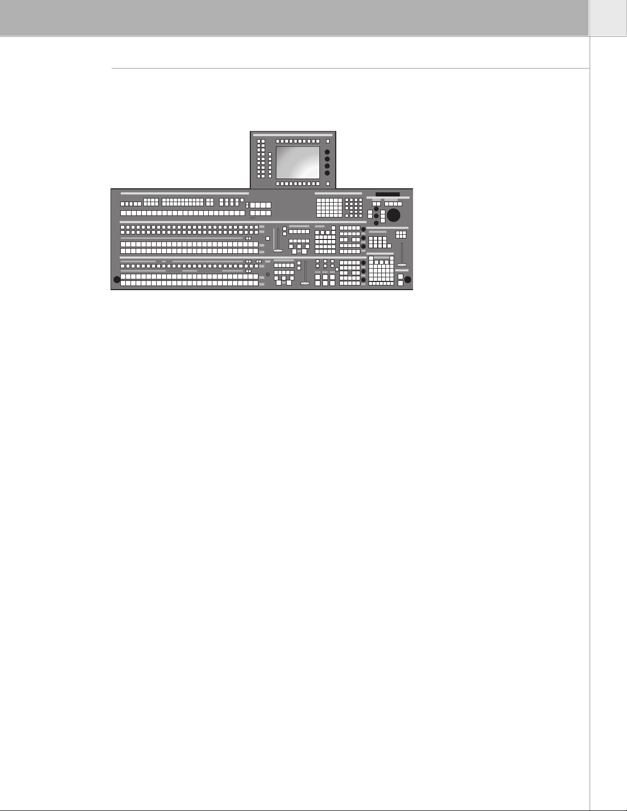
RPS35-4, 32 source button control panel set with dedicated Cut and Auto
push buttons for each keyer, redundant power supply, and input mnemonics.
The control panel set includes:
• Main Panel RPD35-4/32
• Auxiliary Bus Panel RPA35-4/32
• Wipe Selection Panel RPW35
• Menu Display Panel RPV35 with touch-screen
Many customers prefer to mount these in a specially designed desk where
the RPV, RPA, and RPW can be located according to operational needs.
Interconnection cables of approx. 1 meter are provided.
Two optional cable sets are available for more distant mounting – replacing
the standard cable set. (See models RC 2214 and RC 2216 under “À la Carte
Ordering” for details.)
The optional all-in-one mounting frame for RPS35-4 mounts on the back of
the main panel and provides mounting for RPA, RPV (tiltable), and RPW panels.
(See the model RC 2840 under “À la Carte Ordering” below for details.)
The optional stand for graphical user interface provides mounting for the RPV
panel. (See the model RC 2397 under “À la Carte Ordering” below for details.)
See “À la Carte
Ordering” for details
on MI 3040B
Machine Interface,
GPI-OUT TS 3A A
GPI output box, and
GPI-OUT SUB 3A B GPI
output box.
For more options see
below, under “Software
Options” and the “À la
Carte Ordering Guide.”
8 XtenDD Ordering Guide
Page 9
XtenDD-3 Order Number 0 211 908 810
F0-211908-810
Production switcher for serial digital video signals according to ITU-R 601/656.
Switcher package includes the following:
• Three mix effects (M/E-1, M/E-2, P/P)
• 10-bit processing / 270 Mb/s
• 625/525 line standard, switchable or autodetect
• 4:3/16:9 switchable per M/E, manually or per GPI
• 19", 7 RU housing
• 20m connection cable (CAT5, 10Base-T, RJ-45)
• 10Base-T Ethernet switch powered from control panel
• 10Base-2 (BNC) connection for 50Ω RG58 cable is available as an option
• Redundant power supply
• Dedicated outputs 2xPGM, 1xPVW, 1 x clean feed (programmable) per M/E
• Four full function keyers plus one FxLoop keyer per M/E
• Two flexible Dynachrome chroma keyers
• Two flexible wipe generators
• MaKe Memo macros – now with macro editor
• TiM/E Memo memory system for timelines and snapshots with 100 registers
per M/E, plus 100 in the independent master
• 36 non-looping inputs
• 10 auxiliary buses (connectors provided for 20)
• Auxiliary buses are timed and provide Center Cross and adjustable Safe
Area Markers (switchable)
XtenDD Orderi ng Guide 9
Page 10

XtenDD Orderi ng Guide 11
SD S WIT CHE R PACKAGES
Serial Tally
Serial tally enables control systems (Andromeda, Jupiter, or third-party) to
receive and send tally information. For customers not using one of these,
the following tally break-out boxes are available to convert the serial tally
information into parallel semiconductor relay closures:
RPS35-3 control panel set with redundant power supply and input
mnemonics.
The control panel set includes:
• Main Panel RPD35-3
• Auxiliary Bus Panel RPA35-3
• Wipe Selection Panel RPW35
• Menu Display Panel RPV35 with touch-screen
Many customers prefer to mount these in a specially designed desk where
the RPV, RPA, and RPW panels can be located according to operational needs.
Interconnection cables of approx. 1 meter are provided.
Two optional cable sets are available for more distant mounting – replacing
the standard cable set. (See models RC 2214 and RC 2216 under “À la Carte
Ordering” for details.)
The optional all-in-one mounting frame for RPS35-3 mounts on the back of
the Main Panel and provides mounting for RPA, RPV (tiltable) and RPW panels.
(See model RC 2360 under “À la Carte Ordering” below for details.)
The optional stand for graphical user interface provides mounting for the RPV
panel. (See the model RC 2397 under “À la Carte Ordering” below for details.)
See “À la Carte
Ordering” for details
on MI 3040B
Machine Interface,
GPI-OUT TS 3A A
GPI output box, and
GPI-OUT SUB 3A B GPI
output box.
For more options see
below, under “Software
Options” and the “À la
Carte Ordering Guide.”
10 XtenDD Ordering Guide
Page 11
XtenDD-2 Order Number 0 211 909 010
F0-211909-010
Production switcher for serial digital video signals according to ITU-R 601/656.
Switcher package includes the following:
• Two mix effects (M/E-1, P/P)
• 10-bit processing / 270 Mb/s
• 625/525 line standard, switchable or autodetect
• 4:3/16:9 switchable per M/E, manually or per GPI
• 19", 7 RU housing
• 20m connection cable (CAT5, 10Base-T, RJ-45)
• 10Base-T Ethernet switch powered from control panel
• 10Base-2 (BNC) connection for 50Ω RG58 cable is available as an option
• Redundant power supply
• Dedicated outputs 2xPGM, 1xPVW, 1 x clean feed (programmable) per M/E
• Four full function keyers plus one FxLoop keyer per M/E
• Two flexible Dynachrome chroma keyers
• Two flexible wipe generators
• MaKe Memo macros – with macro editor
• TiM/E-Memo memory system for timelines and snapshots with 100
registers per M/E, plus 100 in the independent master
• 18 non-looping inputs
• Five auxiliary buses (connectors provided for 20)
• Auxiliary buses are timed and provide Center Cross and adjustable Safe
Area Markers (switchable)
XtenDD Orderi ng Guide 11
Page 12

XtenDD Orderi ng Guide 13
SD S WIT CHE R PACKAGES
Serial Tally
Serial tally enables control systems (Andromeda, Jupiter, or third-party) to
receive and send tally information. For customers not using one of these,
the following tally break-out boxes are available to convert the serial tally
information into parallel semiconductor relay closures:
RPS35-2 control panel set with redundant power supply and input
mnemonics
The control panel set includes:
• Main Panel RPD35-2
• Menu Display Panel RPV35 with touch-screen
Many customers prefer to mount these in a specially designed desk where the
RPV can be located according to operational needs. Interconnection cables of
approx. 1 meter are provided.
An optional cable set is available for more distant mounting – replacing the
standard cable set. (See the model RC 2216 under “À la Carte Ordering” for
more details.)
The optional graphical user interface (GUI) mounting frame mounts on top of
the main panel and provides mounting for the RPV panel. (See the model RC
2396 under “À la Carte Ordering” below for details.)
The optional stand for graphical user interface provides mounting for the RPV
panel. (See the model RC 2397 under “À la Carte Ordering” below for details.)
See “À la Carte
Ordering” for details
on MI 3040B
Machine Interface,
GPI-OUT TS 3A A
GPI output box, and
GPI-OUT SUB 3A B GPI
output box.
For more options see
below, under “Software
Options” and the “À la
Carte Ordering Guide.”
12 XtenDD Ordering Guide
Page 13
XtenDD-2C Order Number 0 211 909 210
F0-211909-210
Production switcher for serial digital video signals according to ITU-R 601/656.
Switcher package includes the following:
• Two mix effects (M/E-1, P/P)
• 10-bit processing / 270 Mb/s
• 625/525 line standard, switchable or autodetect
• 4:3/16:9 switchable per M/E, manually or per GPI
• 19", 7 RU housing
• 20m connection cable (CAT5, 10Base-T, RJ-45)
• 10Base-T Ethernet switch powered from control panel
• 10Base-2 (BNC) connection for 50Ω RG58 cable is available as an option
• Redundant power supply
• Dedicated outputs 2xPGM, 1xPVW, 1x clean (programmable) per M/E
• Four full function keyers plus one FxLoop keyer per M/E
• One flexible Dynachrome chroma keyer
• One flexible wipe generator
• MaKe Memo macros – now with macro editor
• TiM/E Memo memory system for timelines and snapshots with 100 registers
per M/E, plus 100 in the independent master
• 36 non-looping inputs
• Five auxiliary buses (connectors provided for 20)
• Auxiliary buses are timed and provide Center Cross and adjustable Safe
Area Markers (switchable)
Serial Tally
Serial tally enables control systems (Andromeda, Jupiter, or third-party) to
receive and send tally information. For customers not using one of these,
the following tally break-out boxes are available to convert the serial tally
information into parallel semiconductor relay closures:
RPS35-2S control panel with redundant power supply and input mnemonics.
The control panel comes in one piece.
See “À la Carte
Ordering” for details
on MI 3040B
Machine Interface,
GPI-OUT TS 3A A
GPI output box, and
GPI-OUT SUB 3A B GPI
output box.
For more options see
below, under “Software
Options” and the “À la
Carte Ordering Guide.”
XtenDD Orderi ng Guide 13
Page 14

XtenDD Orderi ng Guide 15
SD S WIT CHE R PACKAGES
OPTION PACKAGES
XtenDD I/O Plus Order no: 0 211 909 310
F0-211909-310
XtenDD I/O Plus Package
These can be added to all switcher packages, above. This package adds:
• 18 non-looping inputs
• Five auxiliary buses
• Two flexible Dynachrome chroma keys
• Two flexible wipe generators
XtenDD I/O Value Order no: 0 211 908 510
F0-211908-510
XtenDD I/O Value Package
These can be added to all switcher packages, above. This package adds:
• 36 non-looping inputs
• 10 auxiliary buses
• Two flexible Dynachrome chroma keys
• Two flexible wipe generators
XtenDD I/O Super Order no: 0 211 908 610
F0-211908-610
XtenDD I/O Super Package
These can be added to all switcher packages, above. This package adds:
• 54 non-looping inputs
• 28 auxiliary buses
• Two flexible Dynachrome chroma keys
• Two flexible wipe generators
14 XtenDD Ordering Guide
Page 15

XtenDD-FX Order no: 0 211 908 710
F0-211908-710
XtenDD FX Processor Package
These can be added to all switcher packages, above. This package adds a
fully loaded FX processor providing:
• Four channels of 3D-planar field-based DVE plus page-turn plus light
sourcing, and intersecting planes with full four-channel z-priority
• DVE channels can be operated as single individual DVEs, or in pairs (V+K or
V+V), triple or quadruple channel configuration with built-in combiner
• Effects include cubes, slabs, etc. Global transform is included as well
• Four channels of Instant Access RAMRecorder providing approx. 32 seconds
of storage for moving or still video. Embedded audio is stored as well. The
RAMRecorder provides various operational modes; among them are:
— Normal VTR
— Delay Line – simultaneous record and adjustable delayed playback
— Live slo-motion
— Clip and loop-modes
In E/E the RAMRecorder synchronizes its input signal.
XtenDD Orderi ng Guide 15
Page 16

XtenDD Orderi ng Guide 17
SOFTWARE OP TIONS
SOFTWARE OPTIONS
LK0130 Order no: 0 157 410 130
F0-157410-130
M/E Couple
This option allows the operator to couple one mix effects bank to another.
Crosspoint selections and transitions in the “master” mix effects bank are also
done in the coupled mix effects bank.
The flexibility of this feature allows you to automatically substitute crosspoints,
as well as define which operations are actually coupled. When one M/E is
coupled to another the crosspoint selection on background, background
preset, and the transition (CUT, AUTO, and T-Bar) are coupled by default.
A separate selection enables the coupling of key/fill crosspoints and a third
selection enables coupling of the next transition selection.
Existing customers use this feature for a wide range of applications, including
4:3/16:9 simulcasting, secondary client output, video wall feeds, etc.
LK0131 Order no: 0 157 410 131
F0-157410-131
Extra Internal DSK
This option for the Standard-Definition XtenDD enables four more DSKs for a
total of eight cascaded DSKs.
This option for the High-Definition HD XtenDD enables three more DSKs for a
total of six cascaded DSKs.
One additional M/E processor RY 3410 is required.
This option is not available for 4 M/E switchers due to space limitations.
Example:
An XtenDD-3 with this option plus an additional M/E-Card (which is then in the
M/E-3 slot) provides the following different outputs:
Connector Signal
PP-PGM P/P-Background plus DSK1-4
PP-Clean Programmable in between background only and background
plus DSK1-4
PP-PVW Preview for background plus DSK1-4
ME3-PGM P/P-background plus DSK1-8
ME3-Clean Programmable in between background plus DSK1-4 and
background plus DSK1-8
ME3-PVW Preview for DSK5-8
16 XtenDD Ordering Guide
Page 17

LK0132 Order no: 0 157 410 132
F0-157410-132
Virtual Patch Panel
This option allows you to remap physical inputs.
It is essentially useful when applications, such as timelines, snapshots, and
macros from other XtenDD switchers, need to be imported. It is also very
useful in the emergency case of a failure of a needed VTR, camera, or server,
allowing for rapid substitution.
With this feature, for example, VTR8 can be used instead of the faulty VTR5
– and no snapshot, timeline, or macro needs to be re-built (as VTR5 is now
“patched” to VTR8).
XtenDD Orderi ng Guide 17
Page 18

XtenDD Orderi ng Guide 19
ACCESSORI ES
ACCESSORI ES
RSAT1 Order no: 0 351 863 610
F0-351863-610
Satellite Panel 1
The Satellite Panel 1 is used for copying button functions of the XtenDD/DD35
main operation panels for control of mixer functions from another surface.
Connects to XtenDD/DD35 main panel or RSE1 via RS-422 cable (5m
included). One satellite panel can be connected to the main panel; additional
satellite panels can be connected using the RSE1 controller (one satellite
panel per RSE1).
Besides single button functions, the built in Digipots and the Fader can also be
trained with functions from the main panel when the learn mode is applied.
Application Examples:
Remote control on source selection, effects register recall, transitions, macros,
Shot-box, keyer adjust, etc., specifically in conjunction with the use of an
additional side-panel control PC.
Various pre-made configurations are available.
Control Elements:
• 4x Digipots
• 6x5 button matrix, programmable with LEDs
• 2x Menu-Ctrl. buttons (step up/down)
• 1x display mode button (name<—>value)
• 1x fader (T-bar)
Display Elements:
• 16 character menu-function LEDs
• 4x4 character LEDs (i.e., 1x per Digipot)
• Serial connection status display
In learn mode only one function per button or Digipot is programmable.
Delegation functions are not available. Also, functions of the RPV side-panel
display are not recordable.
The programmable memory of the RSAT1 is part of the XtenDD/DD35. Thus
the programmed function set for the RSAT1 buttons can be switched from
application to application. More complex button sequences can be achieved
by programmed recall of macro buttons of the main panel.
The standard unit is equipped with 1x reconfigurable 9-pin D-sub interface for
connection to a host processor. The factory configuration is a RS-422/485 port
on the bottom side.
18 XtenDD Ordering Guide
Page 19

Width: 143 mm, Length: 270 mm
Power supply by separate power supply unit (included)
Customer manual
Ext. power supply block (w. Euro plug)
Wide AC range power supply block (90- 264V, ca.15W)
Plug-in adapters – US, UK, and Australia are included
RSAT2 Order no: 0 351 860 810
F0-351860-810
Satellite Panel 2
The RSAT2 is used for detaching or copying of functions of one switcher M/E,
which are then operated from a different location. There are some pre-defined
function sets, but as with the RSAT1 the functions can also be learned. The
connection is made usually with an RS-422 cable (5m included) to a XtenDD/
DD35 control panel. One satellite panel can be connected to the main panel;
additional satellite panels can be connected using the RSE1 controller (one
satellite panel per RSE1). RSAT2 panels connected via RSE1 controller operate
independent of the main control panel, which is desired for many applications.
The panel can be mounted in table or console. A mounting frame is available
for rack mounting. (19-inch rack mount frame, 6 RU. Type: RC 2326 order no:
0 351 762 600 resp. F0-351762-600)
Inclusive button inlays for standard M/E control.
Application Examples:
• Rehearsal panel: located on-stage this enables the director to see and
work with the camera’s signals while working interactively with the talent
on the stage
• Sub-control: an assistant prepares effects in one M/E
• Secondary control: in many cases (especially in OB vans) there is the need
to generate and submit a signal for secondary clients. Depending on the
complexity this can be an aux bus but also a complete M/E. In the latter
case RSAT2 is an ideally suited panel.
• Compact control panel for -1 mainframe
XtenDD Orderi ng Guide 19
Page 20

XtenDD Orderi ng Guide 21
ACCESSORI ES
This application does not use a “main” control panel. The RSAT2 is integrated
into the LAN using an RSE1 controller. Usually the system is configured by a
GUI-PC.
Control Elements:
Program, preset, and key row with 16 buttons each. Mnemonic displays for
source names. Transition section with CUT and T-bar.
• 4x Digipots
• 7x3 Button matrix, programmable with LEDs
• 2x Menu-Ctrl. buttons (step up/down)
• 1x Display mode button (Name<—>Value)
Display Elements:
• 16-character menu function LEDs
• 4x4 character LEDs (i.e., 1x per Digipot)
• Serial connection status display
• Source mnemonics
• “On-air” status
Connectors:
• 1x RS-422 (9-pin D-sub female)
• 1x IEC 320 C14 (AC power supply 85-265V AC, 47-63 Hz, current
consumption max. 0.7A @ 200V 1.4A @ 100V inrush current 15A/30A @
100V/200V AC
Dimensions and Weight:
LxWxD (mm): 464 x 240 x 58
LxWxD (in.): 182.7 x 94.5 x 22.8
Desk cut-out (mm): 441 x 217
Desk cut-out (in.): 173.63 x 85.44
Weight: approx 4 kg (8.8 lbs.)
Options:
19" rackmount frame, 6 RU (RC 2326 order no: 0 351 762 600
resp. F0-351762-600)
RSE1 Order no: 0 212 320 000
F0-212320-000
Stand-Alone Controller
With 19", 1 RU housing, built-in power supply, serial ports and LAN
connection. Together with Switcher Operating Software DS0205 (included) the
RSE1 can be used to connect:
• Additional auxiliary control panels (max. 10 per RSE1)
• Additional under monitor displays (max. 32 per RSE1)
• One satellite panel (either RSAT1 or RSAT2)
20 Xt enDD Ordering Guide
Page 21

DS 0205 Order no: 0 038 060 500
F0-038060-500
Switcher Operating Software
Needs to be ordered for software update.
RC 2351 Order no: 0 351 772 100
F0-351772-100 with initial order only
Fanless Power Supply Panel RPS35-4/3/2/2S
Replaces the standard and redundant power supply for the control panels.
The fanless power supply is a redundant power supply. Heat-pipe technology
is used instead of fans in order to reduce noise in the control room. Extra
space is needed behind the panel for installation. (Dimensions (approx.): width
45 cm (18 in.), depth 20 cm (8 in.), height 10 cm (4 in.) at the center of the
panel. (For exact figures refer to the “XtenDD Planning Information Guide” or
customer documentation.)
RP x C-UMD series
Under-Monitor Displays (UMDs)
Thomson brand Under-Monitor Displays can be connected directly to frame
(max. 32 units), control panel (max. 32 units), and RSE1 (max. 32 units).
AUX-CP JUP-CP-300
JUP-CP-330
JUP-CP-3020
JUP-CP-3021
Auxiliary Bus Control Panels
The listed types of control panels can be connected to frame (max. four
units), control panel (max. 10 units), and RSE1 (max. 10 units) for crosspoint
selection, and TiM/E Memo shotbox.
JUP-CP-300: 1 RU, 24 source selection buttons, six delegation buttons. Power
Supply: 5 VDC external (e.g., JUP-UNIVPS-110/220). (See pricelist Chapter
Routers – Series 300 Control Panels for details.)
JUP-CP-330: 1 RU, 48 source selection buttons, six delegation buttons. Power
Supply: 5 VDC external (e.g., JUP-UNIVPS-110/220). (See pricelist Chapter
Routers – Series 300 Control Panels for details.)
JUP-CP-3020: 1 RU, 20 large source selection buttons, two delegation
buttons. Power Supply 110/220 VAC. (See pricelist Chapter Routers –
Series 3000 Control Panels for details.)
JUP-CP-3021: 1 RU, 20 large pushbutton extension panel for JUP-CP-3020.
(See pricelist Chapter Routers – Series 3000 Control Panels for details.)
XtenDD Orderi ng Guide 21
Page 22

XtenDD Orderi ng Guide 23
ACCESSORI ES
Tally Interfaces
MI-3040B Order no: F7-029500-515
Machine interface provides 40 tally outputs and 40 tally inputs with screw
terminals, 2 RU. Used for tally.
GPI-OUT TS3A A Order no: 0 971 270 000
F0-971270-000
GPI output box provides 48 (40 used by XtenDD) tally outputs with screw
terminals, 1RU. Used for tally.
GPI-OUT SUB3A B Order no: 0 971 280 000
F0-971280-000
GPI output box provides 48 (40 used by XtenDD) tally outputs on two 50-pin
D-sub connectors, 1 RU. Used for tally.
22 Xt enDD Ordering Guide
Page 23

À LA CARTE ORD ERI NG
À LA CARTE ORDERI NG
With à la carte ordering it is possible to tailor the switcher to specific applications. For example, it is
possible to order a different size control panel or a switcher without wipe generators.
Control Panels
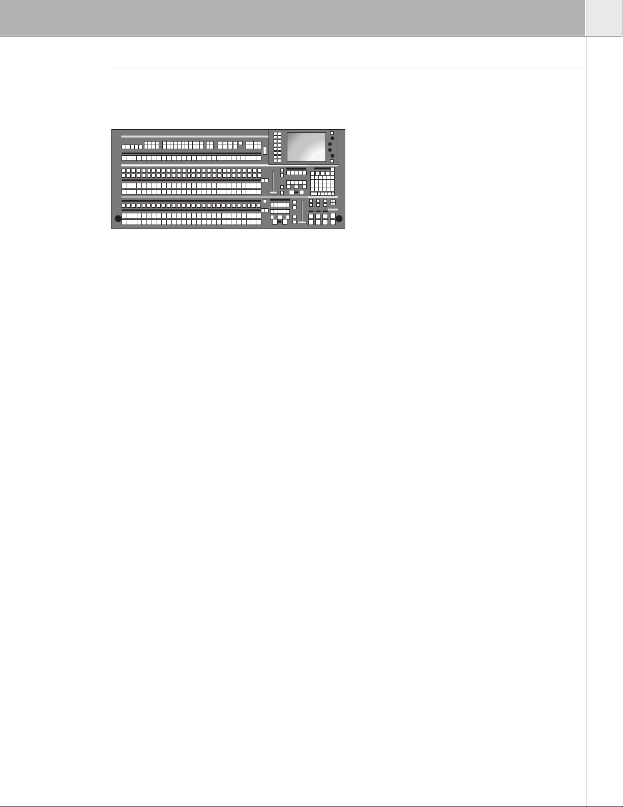
RPS35-4 HL Order no. 0 351 863 310
F0-351863-310
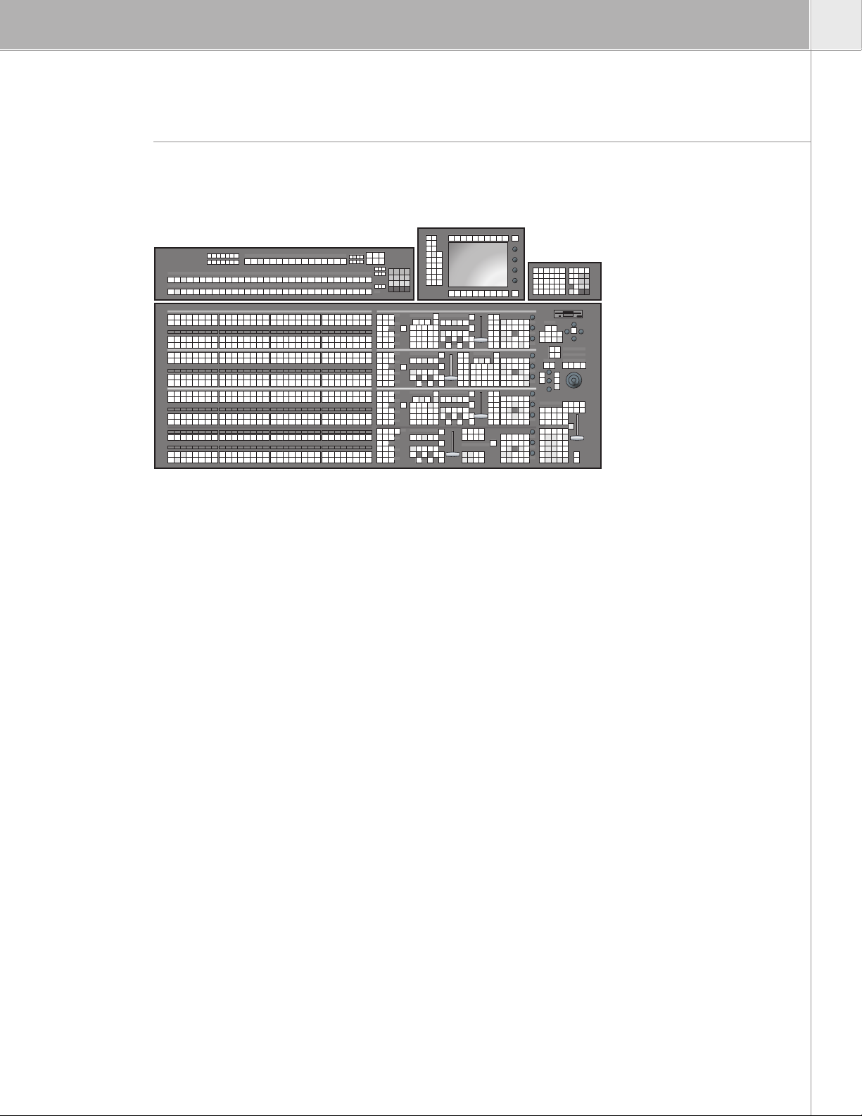
3 M/E Plus P/P Control Panel
32 source button control panel with dedicated cut and auto push buttons for
each keyer, redundant power supply, and input mnemonics.
Includes:
• 20m connection cable (CAT5, 10Base-T, RJ-45)
• 10Base-T Ethernet switch powered from control panel
• 10Base-2 (BNC) connection for 50Ω RG58 cable is available as an option
The control panel set includes:
• Main Panel RPD35-4/32
• Auxiliary Bus Panel RPA35-4/32
• Wipe Selection Panel RPW35
• Menu Display Panel RPV35 with touch-screen
Interconnection cables with approx. 1m lengths are provided
XtenDD Orderi ng Guide 23
Page 24

XtenDD Orderi ng Guide 25
À LA CARTE ORD ERI NG
RC 2214 Order no: 0 351 747 000
F0-351747-000
Cable set for RPA or RPW with length approx. 2.5m. If both RPA and RPW are
to be mounted at a distance two sets have to be ordered.
RC 2216 Order no: 0 351 747 200
F0-351747-200
Cable set for RPV; with length approx. 5m. Cable set is provided for more
distant mounting – replacing the standard cable set.
RC 2840 Order no: 0 351 854 000
F0-351854-000
All-in-one mounting frame for RPS35-4 mounts on the back of the main panel
and provides mounting for RPA, RPV (tiltable), and RPW. With the mounting
frame the panel installation needs only one, larger cutout.
RC 2397 Order no: 0 351 777 510
F0-351777-510
Stand for Graphical User Interface. This is a separate adjustable (pan and tilt)
stand that provides mounting for the RPV.
The cable set RC 2216 is recommended when this item is ordered.
24 Xt enDD Ordering Guide
Page 25

RPS35-3 HL Order no. 0 351 862 310
F0-351862-310
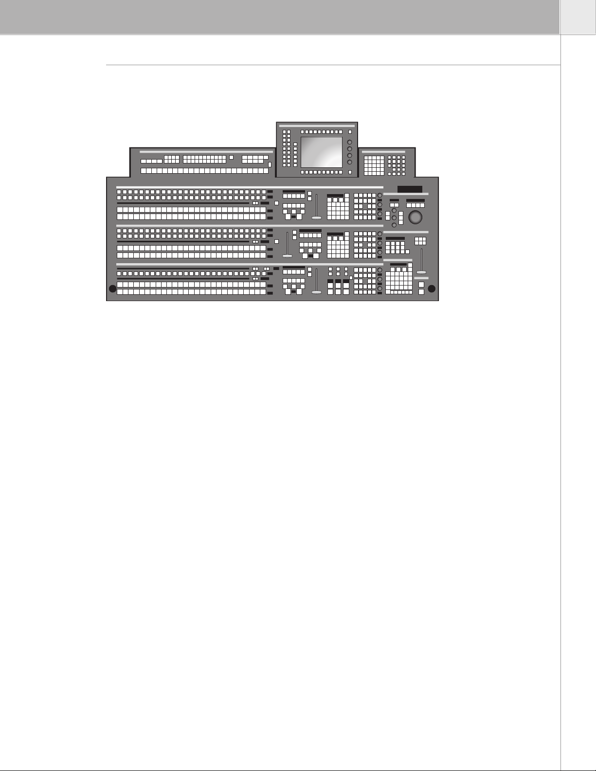
2 M/E Plus P/P Control Panel
Control panel with 24 source select buttons, redundant power supply, and
input mnemonics
Includes:
• 20m connection cable (CAT5, 10Base-T, RJ-45)
• 10Base-T Ethernet switch powered from control panel
• 10Base-2 (BNC) connection for 50Ω RG58 cable is available as an option.
The control panel set includes:
• Main Panel RPD35-3
• Auxiliary Bus Panel RPA35-3
• Wipe Selection Panel RPW35
• Menu Display Panel RPV35 with touch-screen
Interconnection cables with approx.1 meter lengths are provided.
RC 2214 Order no: 0 351 747 000
F0-351747-000
Cable set for RPA or RPW. with length approx 2.5m. If both RPA and RPW are
to be mounted at a distance two sets have to be ordered.
RC 2216 Order no: 0 351 747 200
F0-351747-200
Cable set for RPV with length approx. 5m. Cable set is provided for more
distant mounting – replacing the standard cable set.
XtenDD Orderi ng Guide 25
Page 26

XtenDD Orderi ng Guide 27
À LA CARTE ORD ERI NG
RC 2360 Order no: 0 351 773 000
F0-351773-000
All-in-one mounting frame for RPS35-3 mounts on the back of the main panel
and provides mounting for RPA, RPV (tiltable), and RPW. With the mounting the
panel installation needs only one, larger cutout.
RC 2397 Order no: 0 351 777 510
F0-351773-000
Stand for Graphical User Interface. This is a separate adjustable (pan and tilt)
stand that provides mounting for the RPV.
The cable set RC 2216 is recommended when this item is ordered.
26 Xt enDD Ordering Guide
Page 27

RPS35-2 HL Order no: 0 351 862 410
F0-351862-410
1 M/E Plus P/P Control Panel
Control panel with 24 source select buttons, standard power supply, input
mnemonics for P/P, and MaKe Memo
Includes:
• 20m connection cable (CAT5, 10Base-T, RJ-45)
• 10Base-T Ethernet switch powered from control panel
• 10Base-2 (BNC) connection for 50Ω RG58 cable is available as an option
The control panel set includes:
• Main Panel RPD35-2
• Menu Display Panel RPV35 with touch-screen
Interconnection cables with approx. 1 meter lengths are provided.
RC 2376 Order no: 0 351 774 600
F0-351774-600 initial order only
Redundant Power Supply Panel
RC 2362 Order no: 0 351 773 200
F0-351773-200 initial order only
Input mnemonics extension (M/E and AUX) for RPS35-2.
RC 2216 Order no: 0 351 747 200
F0-351747-200
Cable set for RPV with length approx. 5 meters.
Cable set is provided for more distant mounting – replacing the standard
cable set.
XtenDD Orderi ng Guide 27
Page 28

XtenDD Orderi ng Guide 29
À LA CARTE ORD ERI NG
RC 2396 Order no: 0 351 777 410
F0-351777-410
Graphical user interface (GUI) mounting frame mounts on top of the main
panel and provides mounting for RPV.
RC 2397 Order no: 0 351 777 510
F0-351777-510
Stand for graphical user interface. This is a separate adjustable (pan and tilt)
stand that provides mounting for the RPV.
The cable set RC 2216 is recommended when this item is ordered.
RPS35-2S HL Order no: 0 351 862 510
F0-351862-510
Compact 1 M/E Plus P/P Control Panel
Control panel with 28 source select buttons, standard power supply. Input
mnemonics not included.
Includes:
• 20m connection cable (CAT5, 10Base-T, RJ-45)
• 10Base-T Ethernet switch powered from control panel
• 10Base-2 (BNC) connection for 50Ω RG58 cable is available as an option
RC 2376 Order no: 0 351 774 600
F0-351774-600 initial order only
Redundant power supply panel.
RC 2456 Order no: 0 212 265 610
F0-212265-610 initial order only
Input mnemonics for RPS35-2S.
28 Xt enDD Ordering Guide
Page 29

For All Panels
RC 2351 Order no: 0 351 772 100
F0-351772-100 initial order only
Fanless Power Supply Panel RPS35-4/3/2/2S
Replaces standard and redundant power supply for the control panels. The
fanless power supply is a redundant power supply. Heat-pipe technology is
used instead of fans in order to reduce noise in the control room. Extra space
behind the panel is needed for the installation.
RC 2387 Order no: 0 351 776 510
F0-351776-510
Adaptation to BNC (50Ω, RG58) LAN cable replacing the standard RJ-45
connection.
XtenDD Orderi ng Guide 29
Page 30

XtenDD Orderi ng Guide 31
SD B ASI C MAINFRAMES
XtenDD STANDARD-DEFINITION SWITCHER BASIC MAINFRAMES
XMD-4-BM 4 Order no: 0 212 352 410
F0-212352-410
Basic 7 RU Standard-Definition Mainframe for Four Mix Effects (M/E-1, M/E-2, M/E-3, P/P)
Controller, operating software, genlock, aux-bus motherboard, crosspoint
(input processor) card, control module, M/E-cards. This basic mainframe does
not contain input and output modules.
Production switcher for serial digital video signals according to ITU-R 601/656.
Features:
• 10-bit processing / 270 Mb/s
• 625/525 line standard, switchable or autodetect
• 4:3/16:9 switchable per M/E, manually or per GPI
• 19", 7 RU housing
• LAN connector RJ-45
• 10Base-2 (BNC) connection for 50Ω RG58 cable is available as an option
• Dedicated outputs 2xPGM, 1xPVW, 1 x clean (programmable) per M/E
• Four full function keyers plus one FxLoop keyer per M/E
• Standard (non-redundant) power supply
Options:
• Up to four Dynachrome chroma keyers per M/E
• Up to two wipe generators per M/E
• Mask paint store per M/E
• Far shadow store per M/E
• Up to 38 auxiliary busses
Auxiliary buses are timed and provide Center Cross and adjustable Safe Area
Markers (switchable).
• MaKe Memo Macros – with macro editor
• TiM/E Memo Memory System for timelines and snapshots with 100
registers per M/E, plus 100 in the independent master
Serial Tally
Serial tally enables control systems (Andromeda, Jupiter, or third-party) to
receive and send tally information. For customers not using one of these, the
following types of tally break-out boxes can be used:
• MI 3040B Machine Interface provides 40 tally outputs and 40 tally inputs
with screw terminals, 2 RU
• GPI-OUT TS 3A A GPI output box provides 48 (40 used) tally outputs with
screw terminals, 1 RU
• GPI-OUT SUB 3A B GPI output box provides 48 (40 used) tally outputs on
two 50-pin D-sub connectors, 1 RU
It is possible to use one MI 3040 for input and output and GPI output box for
more tally outputs.
30 Xt enDD Ordering Guide
Page 31

XMD-3-BM 4 Order no: 0 212 352 310
F0-212352-310
Basic 7 RU Standard-Definition Mainframe for Three Mix Effects (M/E-1, M/E-2, P/P)
Controller, operating software, genlock, aux-bus motherboard, crosspoint
(input processor) card, control module, M/E-cards. This basic mainframe does
not contain input and output modules.
Production switcher for serial digital video signals according to ITU-R 601/656.
Features:
• 10-bit processing / 270 Mb/s
• 625/525 line standard, switchable or autodetect
• 4:3/16:9 switchable per M/E, manually or per GPI
• 19", 7 RU housing
• LAN connector RJ-45
• 10Base-2 (BNC) connection for 50Ω RG58 cable is available as an option
• Dedicated outputs 2xPGM, 1xPVW, 1 x clean (programmable) per M/E
• Four full function keyers plus one FxLoop keyer per M/E
• Standard (non-redundant) power supply
Options:
• Up to four Dynachrome chroma keyers per M/E
• Up to two wipe generators per M/E
• Mask paint store per M/E
• Far shadow store per M/E
• Up to 38 auxiliary busses
Auxiliary buses are timed and provide Center Cross and adjustable Safe Area
Markers (switchable).
• MaKe Memo Macros – with macro editor
• TiM/E Memo Memory System for timelines and snapshots with 100
registers per M/E, plus 100 in the independent master
Serial Tally
Serial tally enables control systems (Andromeda, Jupiter, or third-party) to
receive and send tally information. For customers not using one of these, the
following types of tally break-out boxes can be used:
• MI 3040B Machine Interface provides 40 tally outputs and 40 tally inputs
with screw terminals, 2 RU
• GPI-OUT TS 3A A GPI output box provides 48 (40 used) tally outputs with
screw terminals, 1 RU
• GPI-OUT SUB 3A B GPI output box provides 48 (40 used) tally outputs on
two 50-pin D-sub connectors, 1 RU
It is possible to use one MI 3040 for input and output and GPI output box for
more tally outputs.
XtenDD Orderi ng Guide 31
Page 32

XtenDD Orderi ng Guide 33
SD B ASI C MAINFRAMES
XMD-2-BM 4 Order no: 0 212 352 210
F0-212352-210
Basic 7 RU Standard-Definition Mainframe for Two Mix Effects (M/E-1, P/P)
Controller, operating software, genlock, aux-bus motherboard, crosspoint
(input processor) card, control module, M/E-cards. This basic mainframe does
not contain input and output modules.
Production switcher for serial digital video signals according to ITU-R 601/656.
Features:
• 10-bit processing / 270 Mb/s
• 625/525 line standard, switchable or autodetect
• 4:3/16:9 switchable per M/E, manually or per GPI
• 19", 7 RU housing
• LAN connector RJ-45
• 10Base-2 (BNC) connection for 50Ω RG58 cable is available as an option
• Dedicated outputs 2xPGM, 1xPVW, 1 x clean (programmable) per M/E
• Four full function keyers plus one FxLoop keyer per M/EE
• Standard (non-redundant) power supply
Options:
• Up to four Dynachrome chroma keyers per M/E
• Up to two wipe generators per M/E
• Mask paint store per M/E
• Far shadow store per M/E
• Up to 38 auxiliary busses
Auxiliary buses are timed and provide Center Cross and adjustable Safe Area
Markers (switchable).
• MaKe Memo Macros – with macro editor
• TiM/E Memo Memory System for timelines and snapshots with 100
registers per M/E, plus 100 in the independent master
Serial Tally
Serial tally enables control systems (Andromeda, Jupiter, or third-party) to
receive and send tally information. For customers not using one of these, the
following types of tally break-out boxes can be used:
• MI 3040B Machine Interface provides 40 tally outputs and 40 tally inputs
with screw terminals, 2 RU
• GPI-OUT TS 3A A GPI output box provides 48 (40 used) tally outputs with
screw terminals, 1 RU
• GPI-OUT SUB 3A B GPI output box provides 48 (40 used) tally outputs on
two 50-pin D-sub connectors, 1 RU
It is possible to use one MI 3040 for input and output and GPI output box for
more tally outputs.
32 Xt enDD Ordering Guide
Page 33

XMD-1-BM 4 Order no: 0 212 352 110
F0-212352-110
Basic 7 RU Standard-Definition Mainframe for One Mix Effects (P/P)
Controller, operating software, genlock, aux-bus motherboard, crosspoint
(input processor) card, control module, M/E-card. This basic mainframe does
not contain input and output modules.
Production switcher for serial digital video signals according to ITU-R 601/656.
Features:
• 10-bit processing / 270 Mb/s
• 625/525 line standard, switchable or autodetect
• 4:3/16:9 switchable per M/E, manually or per GPI
• 19", 7 RU housing
• LAN connector RJ-45
• 10Base-2 (BNC) connection for 50Ω RG58 cable is available as an option
• Dedicated outputs 2xPGM, 1xPVW, 1 x clean (programmable) per M/E
• Four full function keyers plus one FxLoop keyer per M/E
• Standard (non-redundant) power supply
Options:
• Up to four Dynachrome chroma keyers per M/E
• Up to two wipe generators per M/E
• Mask paint store per M/E
• Far shadow store per M/E
• Up to 38 auxiliary busses
Auxiliary buses are timed and provide Center Cross and adjustable Safe Area
Markers (switchable).
• MaKe Memo Macros – with macro editor
• TiM/E Memo Memory System for timelines and snapshots with 100
registers per M/E, plus 100 in the independent master
Serial Tally
Serial tally enables control systems (Andromeda, Jupiter, or third-party) to
receive and send tally information. For customers not using one of these, the
following types of tally break-out boxes can be used:
• MI 3040B Machine Interface provides 40 tally outputs and 40 tally inputs
with screw terminals, 2 RU
• GPI-OUT TS 3A A GPI output box provides 48 (40 used) tally outputs with
screw terminals, 1 RU
• GPI-OUT SUB 3A B GPI output box provides 48 (40 used) tally outputs on
two 50-pin D-sub connectors, 1 RU
It is possible to use one MI 3040 for input and output and GPI output box for
more tally outputs.
XtenDD Orderi ng Guide 33
Page 34

XtenDD Orderi ng Guide 35
SD B ASI C MAINFRAMES
RC3470 Order no: 0 212 347 010
F0-212347-010
Power Supply Unit
(Redundant Power Supply)
Order this power supply unit on initial order to make the mainframe power
supply redundant.
On later order this is the replacement part for the mainframe power supply
(single unit).
RC 2515 Order no: 0 212 247 210
F0-212247-210 initial order only
Adaptation to BNC (50Ω, RG58) LAN cable replacing the standard RJ-45
connection.
34 Xt enDD Ordering Guide
Page 35

Inputs
Equipping the basic mainframe with inputs or upgrade a package requires the necessary hardware (one or
more serial input modules) and a software license that enables the inputs. The input modules are identical
except for the labeling of the BNC connectors.
Examples:
• For a total of 54 enabled and working inputs the following parts need to be ordered (in addition to the basic
frame): RC 3420, RC 3421, RC 3422, and LK0116.
• For later upgrade from 36 inputs to 72 inputs the following parts need to be ordered: RC 3422, RC 3423 and
2 x LK 0205 S
RC 3420 Order no: 0 212 342 010
F0-212342-010
Serial Input 1
Module with 18 non-looping inputs labeled as IN1-18 LK0114 S or higher
required to enable.
RC 3421 Order no: 0 212 342 110
F0-212342-110
Serial Input 2
Module with 18 non-looping inputs labeled as IN19-36 LK0115 S or higher
required to enable.
RC 3422 Order no: 0 212 342 210
F0-212342-210
Serial Input 3
Module with 18 non-looping inputs labeled as IN37-54 LK0116 S or higher
required to enable.
RC 3423 Order no: 0 212 342 310
F0-212342-310
Serial Input 4
Module with 18 non-looping inputs labeled as IN55-72 LK0117 S or higher
required to enable.
RC 3424 Order no: 0 212 342 410
F0-212342-410
Serial Input 5
Module with 18 non-looping inputs labeled as IN73-90 LK0118 S required to
enable.
XtenDD Orderi ng Guide 35
Page 36

XtenDD Orderi ng Guide 37
SD B ASI C MAINFRAMES
LK0114 S Order no: 0 157 410 114
F0-157410-114 initial order only
License for inputs 1-18. No. of inputs: 18.
LK0115 S Order no: 0 157 410 201
F0-212342-210 initial order only
License for inputs 1-36. No. of inputs: 36.
LK0116 S Order no: 0 157 410 202
F0-157410-202 initial order only
License for inputs 1-54. No. of inputs: 54.
LK0117 S Order no: 0 157 410 203
F0-157410-203 initial order only
License for inputs 1-72. No. of inputs: 72.
LK0118 S Order no: 0 157 410 204
F0-157410-204 initial order only
License for inputs 1-90. No. of inputs: 90.
LK0205 S Order no: 0 157 410 205
F0-157410-205 later order or package upgrade only
License upgrade for packages and installed XtenDD switchers. Increases the
number of enabled inputs by 18. S/N of mainframe must be specified in order.
36 Xt enDD Ordering Guide
Page 37

Outputs and Aux-Buses
Equipping the basic mainframe with outputs or upgrading a package with aux buses requires the necessary
hardware (serial output modules and aux-bus modules) and a software license that enables the auxiliary
busses. The serial output modules are identical except for the labeling of the BNC connectors. The aux-bus
modules are also identical. Maximum seven modules can be installed. Configurations are possible with the
following quantity of auxiliary buses: 5, 10, 15, 20, 26, 32, 38.
RC 3450 Order no: 0 212 345 010
F0-212345-010
Serial Output 1
Module with BNC connectors for 10 aux buses (labeled as AUX1 – AUX 10)
plus the direct outputs (PGM 2x, PVW, Clean) for M/E-1 and P/P.
This hardware is
strongly recommended/
needed for all XtenDD
configurations.
RC 3451 Order no: 0 212 345 110
F0-212345-110
Serial Output 2
Module with BNC connectors for 10 aux buses (labeled as AUX11 – AUX 20)
plus the direct outputs (PGM 2x, PVW, Clean) for M/E-2 and M/E-3.
This hardware is
strongly recommended/
needed for 3 and 4
M/E configurations.
RC 3452 Order no: 0 212 345 210
F0-212345-210
Serial Output 3
Module with BNC connectors for 18 aux buses (labeled as AUX21 – AUX 38).
RY 3435 Order no: 0 212 343 510
F0-212343-510
Aux Bus Processor Module
Mezzanine board, mounts on the aux bus motherboard, provides phasing,
safe-area and center cross insertion, and (switchable) H/V blanking.
One module is required per set of 5/6 aux buses.
LK0123 S Order no: 0 157 410 247
F0-157410-247 initial order only
No. of aux buses: five. License for five aux buses. Enables AUX1 – AUX5.
LK0124 S Order no: 0 157 410 206
F0-157410-206 initial order only
No. of aux buses: 10. License for 10 aux buses. Enables AUX1- AUX10
XtenDD Orderi ng Guide 37
Page 38

XtenDD Orderi ng Guide 39
SD B ASI C MAINFRAMES
LK0125 S Order no: 0 157 410 207
F0-157410-207 initial order only
No. of aux buses: 15. License for 15 aux buses. Enables AUX1 – AUX15.
LK0126 S Order no: 0 157 410 208
F0-157410-208 initial order only
No. of aux buses 20. License for 20 aux buses. Enables AUX1 – AUX20.
LK0127 S Order no: 0 157 410 209
F0-157410-209 initial order only
No. of aux buses 26. License for 26 aux buses. Enables AUX1 – AUX26.
LK0128 S Order no: 0 157 410 210
F0-157410-210 initial order only
No. of aux buses 32. License for 32 aux buses. Enables AUX1 – AUX32.
LK0129 S Order no: 0 157 410 211
F0-157410-211 initial order only
No. of aux buses 38. License for 38 aux buses. Enables AUX1 – AUX38.
LK0212 S Order no: 0 157 410 212
F0-157410-212 later order or package upgrade only
License upgrade for packages or installed XtenDD switchers. Increases the no.
of enabled aux buses to the next step. S/N of mainframe must be specified in
order.
# AUX: what to order for a number of aux buses with any basic mainframe
5 RC 3450
1x RY 3435
LK0123 S
10 RC 3450
2x RY 3435
LK0124 S
15 RC 3450
RC 3451
3x RY 3435
LK0125 S
20 RC 3450
RC 3451
4x RY 3435
LK0126 S
26 RC 3450
RC 3451
RC 3452
5x RY 3435
LK0127 S
32 RC 3450
RC 3451
RC 3452
6x RY 3435
LK0128 S
38 RC 3450
RC 3451
RC 3452
7x RY 3435
LK0129
38 Xt enDD Ordering Guide
Page 39

M/E Upgrades
Select the amount of hardware and the related licenses to upgrade the basic mainframe with mix effects banks.
RY 3410.1 Order no: 0 212 341 011
F0-212341-010
M/E Processor
Hardware to add one M/E to an XtenDD switcher mainframe.
Provides four linear and luminance keyers with border liner.
Options:
• Dynachrome chromakeying for any M/E keyer
• Up to two wipe generators
• Mask paint store
• Far shadow store
One M/E processor board is required per added M/E.
License Keys: later order and package upgrades
S/N of mainframe must be specified for upgrade of installed XtenDD switchers.
LK 0179 S Order no: 0 157 410 179
F0-157410-179
License upgrade from one M/E (P/P) to two M/E (M/E-1, P/P)
LK 0180 S Order no: 0 157 410 180
F0-157410-180
License upgrade from two M/E (M/E-1, P/P) to three M/E (M/E-1, M/E-2, P/P)
LK 0181 S Order no: 0 157 410 181
F0-157410-181
License upgrade from three M/E (M/E-1, M/E-2, P/P) to four M/E (M/E-1,
M/E-2, M/E-3, P/P)
XtenDD Orderi ng Guide 39
Page 40

XtenDD Orderi ng Guide 41
SD B ASI C MAINFRAMES
COMMON OPT IO NS FO R SD BASIC MAINFRAMES
Dynachrome Chroma Keyers
Based on a matting technique, Dynachrome achieves excellent detail and shadow reproduction, with
virtually no color spill. Clip, gain, and FGD-fade can reduce background noise and eliminate most unwanted
shadows. The automatic key alignment (AKA) is pre-adjustable for any key color. The cursor allows an AKA
for every key color. Manual adjustment is possible, as well as separate adjustment for both adjacent hues
(selectivities) and a radial displacement away from the center of the color circle. Selectivity masking allows
different chroma-key settings to be simultaneously executed in different image areas within single keyers.
Dynachrome chroma keyers for the XtenDD can be ordered flexible for dynamic user assignment to a
selected keyer.
Flexible Chroma Keyers
LK0120 S Order no: 0 157 410 221
F0-157410-221 initial order only
Flexible chroma keyer. Enables one flexible chroma keyer.
LK0242 S Order no: 0 157 410 242
F0-157410-242 later order or package upgrade only
Flexible chroma keyer for upgrading packages or installed XtenDD
switchers. Enables one flexible chroma keyer. S/N of mainframe must be
specified in order.
Wipe Generators
One wipe generator provides 100 basic (rectangles, circle, ellipse, etc.) and fancy patterns (stars, spirals,
matrix, etc.) – including DD’s fractal wipes. A full set of modifiers (border, softness, aspect, stretch, multi,
rotation, etc.) is also provided.
Wipe generators are available flexible for user selection of where the wipe is used. Maximum of two wipe
generators can be used per M/E.
When there are two wipe generators in one M/E they can be combined to generate even more creative
shapes.
Flexible Wipe Generators
LK0119 S Order no: 0 157 410 244
F0-157410-244 initial order only
Flexible wipe generator. Enables one flexible wipe generator.
LK0243 S Order no: 0 157 410 243
F0-157410-243 later order or package upgrade only
Flexible wipe generator for upgrading packages or installed XtenDD
switchers. Enables one flexible wipe generator. S/N of mainframe must be
specified in order.
40 Xt enDD Ordering Guide
Page 41

Far Shadow Stores
A far shadow store is a black-and-white store that can generate a movable drop shadow from any key
signal. It is available once per M/E. The far shadow store extends the borderline capabilities of the mix
effects’s keyers by a freely positionable drop shadow. It can be selected through the “border” function.
A flexible far shadow store license (maximum one per M/E) allows assignment of the far shadow store
function to any M/E. It then can be used in any keyer of that M/E bank.
LK0294 S Order no: 0 157 410 294
F0-157410-294 initial order
Enables shadow store in flexible shadow store.
LK0295 S Order no: 0 157 410 295
F0-157410-295 later order or package upgrade
Enables shadow store in flexible shadow store. S/N of mainframe must be
specified in order.
Paint Mask Stores
(Also known as paint stores)
A paint mask store is a black-and-white store that can store a key signal for PaintModeMasking™. It is
available once per M/E. The key signal on the store’s input can be one of the keyer’s output signals or one
of the wipe pattern generators. Since the store is fully recursive, users can paint their own shapes into the
store using a wipe pattern, such as the circle wipe, as a paintbrush. By adjusting the softness of the wipe
shape the resulting shape can have soft edges. The stored shape is movable (shift function) and can be
used for masking and for keying.
A flexible paint mask store license (maximum one per M/E) allows assignment of the paint mask store
function to any M/E. It then can be used in any keyer of that M/E bank.
LK0298 S Order no: 0 157 410 298
F0-157410-298 initial order
Enables mask paint store in flexible paint mask store.
LK0299 S Order no: 0 157 410 299
F0-157410-299 later order or package upgrade
Enables mask paint store in flexible paint mask store. S/N of mainframe must
be specified in order.
XtenDD Orderi ng Guide 41
Page 42

XtenDD Orderi ng Guide 43
SD B ASI C MAINFRAMES
Effects Processor
XtenDD FX processor
A fully loaded FX Processor provides four channels of 3D-planar field-based DVE, plus page-turn and dual
light sourcing, intersecting planes with full four-channel z-priority.
DVE channels can be operated as single individual DVEs, or in pairs (V+K or V+V), triple, or quadruple
channel configuration with built-in combiner.
Effects include cubes, slabs, etc. Global transform is included as well.
Four channels of instant access RAMRecorder providing approx. 32 seconds of storage for moving or still
video. Embedded audio is stored as well. The RAMRecorder provides various operational modes; such as:
• Normal VTR
• Delay line
• Live slo-motion
• Clip and loop-modes
In E/E the RAMRecorder synchronizes its input signal.
To operate the DVE and RAMRecorder function it is necessary to have the hardware equipped as well as
have the appropriate license key installed.
RY 3460 Order no: 0 212 346 010
F0-212346-010
Effects Processor Board
A software license is required. On-board connectors can hold a RAMRecorder
module (RY 3465).
LK0133 Order no: 0 157 410 133
F0-157410-133 intial order only
License to enable two channels of DVE (Channels 1+2).
LK0134 Order no: 0 157 410 134
F0-157410-134 intial order only
License to enable four channels of DVE (Channels 1-4).
LK0137 Order no: 0 157 410 137
F0-157410-137 later order
License to enable two channels of DVE. This can be used for later upgrade
from two to four channels or to license the effects processor for a second
mainframe. S/N of mainframe must be specified in order.
LK0176 S Order no: 0 157 410 246
F0-157410-246
Page Turn effect. S/N of mainframe must be specified in later order.
42 Xt enDD Ordering Guide
Page 43

RY 3465.1 Order no: 0 212 346 511
F0-212346-511
RAMRecorder Module
The RAMRecorder module installs on the FX processor (RY 3460) to provide
four channels of approx. 16 seconds storage each, for uncompressed stills
and video sequences, including embedded audio.
LK0135 Order no: 0 157 410 135
F0-157410-135 intial order only
License to enable two channels of RAMRecorder (Channels 1+2) for approx.
32 seconds storage.
LK0136 Order no: 0 157 410 136
F0-157410-136 intial order only
License to enable four channels of RAMRecorder (Channels 1-4) for approx.
64 seconds storage.
LK0138 Order no: 0 157 410 138
F0-157410-138 later order
License to enable two channels of RAMRecorder. This can be used for later
upgrade from two to four channels or to license the RAMRecorder for a
second mainframe. S/N of mainframe must be specified in order.
LK0175 S Order no: 0 157 410 245
F0-157410-245
Image File Transfer
Between RAMRecorder and Sidepanel PC or external PC running XtenDD
software. S/N of mainframe must be specified in later order.
LK0177 S Order no: 0 157 410 292
F0-157410-292
Image Converter
This separate program runs on Windows PC and converts from XtenDD image
files to several standard graphics file formats (export) and vice versa (import).
Supported graphic file formats include JPG, TIF, Targa (PSD import only). AVI
files are supported for animations.
S/N of mainframe must be specified in later order.
XtenDD Orderi ng Guide 43
Page 44

XtenDD Orderi ng Guide 45
HD B ASI C MAINFRAMES
HD XtenDD H IG H- DE FINITION SWITCHER BASIC MA IN FR AM ES
7 RU HD XtenDD Mainframes and Dedicated Options
All 7 RU mainframes
Production switcher for high-definition serial digital video signals (HD-SDI)
according to SMPTE 292M.
Features:
• 10-bit processing / 1.485 Gb/s
• 1080i, 720p, and 1080pSF standards
• Switchable. Reference is selectable, analog Tri-Level sync or HD-SDI
reference input
• 19", 7 RU housing
• 20m connection cable
• LAN connector RJ-45
• 10Base-2 (BNC) connection for 50Ω RG58 cable is available as an option
• Up to two mix effects
• Dedicated outputs 2xPGM, 1xPVW, 1 x clean (programmable) per M/E
• Three keyers per M/E
• Standard (non-redundant) power supply
Options:
• Up to two Dynachrome chroma keyers per M/E
• Up to two wipe generators per M/E
• Mask paint store per M/E
• Far shadow store per M/E
• Up to 10 auxiliary busses
See next section for
12 RU mainframes
Auxiliary buses are timed and provide Center Cross and adjustable Safe Area
Markers (switchable).
• MaKe Memo Macros – with macro editor
• TiM/E Memo Memory System for timelines and snapshots with 100
registers per M/E, plus 100 in the independent master
Serial Tally
Serial tally enables control systems (Andromeda, Jupiter, or third-party) to
receive and send tally information. For customers not using one of these, the
following types of tally break-out boxes can be used:
• MI 3040B Machine Interface provides 40 tally outputs and 40 tally inputs
with screw terminals, 2 RU
• GPI-OUT TS 3A A GPI output box provides 48 (40 used) tally outputs with
screw terminals, 1 RU
• GPI-OUT SUB 3A B GPI output box provides 48 (40 used) tally outputs on
two 50-pin D-sub connectors, 1 RU
It is possible to use one MI 3040 for input and output and GPI output box for
more tally outputs.
44 Xt enDD Ordering Guide
Page 45

SH-1S-BM Order no: 0 212 360 010
F0-212360-010
Basic 7 RU High-Definition Mainframe for One M/E (P/P)
Controller, operating software, and license for one M/E. Input processor with
18 non-looping serial inputs. M/E processor for one M/E. Serial output 1
(connectors for P/P, M/E-1, and 10 aux outputs). Five auxiliary buses included
(upgradeable to 10).
SH-2S-BM Order no: 0 212 360 110
F0-212360-110
Basic 7 RU High-Definition Mainframe for Two M/E (M/E-1, P/P)
Controller, operating software, and license for 2 M/E. Input processor with
18 non-looping serial inputs. M/E processors for 2 M/E. Serial output 1
(connectors for P/P, M/E-1, and 10 aux outputs). Five auxiliary buses included
(upgradeable to 10).
RC 3470 Order no: 0 212 347 010
F0-212347-010
Power Supply Unit (Redundant Power Supply) for 7 RU HD Mainframe
Order this power supply unit on initial order to make the mainframe power
supply redundant.
On later order this is the replacement part for the mainframe power supply
(single unit).
RC 2515 Order no: 0 212 247 210
F0-21247-210 initial order only
Adaptation to BNC (50Ω, RG58) LAN cable replacing the standard RJ-45
connection.
XtenDD Orderi ng Guide 45
Page 46

XtenDD Orderi ng Guide 47
HD B ASI C MAINFRAMES
Input Upgrades for 7 RU HD Mainframes
Input upgrades require the necessary hardware (a serial input module) and a software license that enables
the inputs. The input modules are equal except for the labeling of the BNC connectors.
RC 3611 Order no: 0 212 361 110
F0-212361-110
Serial input 2 for SH-1S-BM and SH-2S-BM. Module with 18 non-looping
inputs labeled as IN19-36. LK0115 H or higher required to enable.
RC 3612 Order no: 0 212 361 210
F0-212361-210
Serial input 3 for SH-1S-BM and SH-2S-BM. Module with 18 non-looping
inputs labeled as IN37-54. LK0116 H or higher required to enable.
RC 3613 Order no: 0 212 361 310
F0-212361-310
Serial input 4 for SH-1S-BM and SH-2S-BM. Module with 18 non-looping
inputs labeled as IN55-72. LK0117 H or higher required to enable.
RC 3614 Order no: 0 212 361 410
F0-212361-410
Serial input 5 for SH-1S-BM and SH-2S-BM. Module with 18 non-looping
inputs labeled as IN73-90. LK0118 H required to enable.
LK0115 H Order no: 0 157 410 250
F0-157410-250 initial order only
License for inputs 1-36. No. of inputs: 36.
LK0116 H Order no: 0 157 410 251
F0-157410-250 initial order only
License for inputs 1-54. No. of inputs: 54.
LK0117 H Order no: 0 157 410 252
F0-157410-252 initial order only
License for inputs 1-72. No. of inputs: 72.
LK0118 H Order no: 0 157 410 253
F0-157410-253 initial order only
License for inputs 1-90. No. of inputs: 90.
LK0254 H Order no: 0 157 410 254
F0-157410-254 later order only
License upgrade. Increases the number of enabled inputs by 18. S/N of
mainframe must be specified in order.
46 Xt enDD Ordering Guide
Page 47

Aux Bus (Output) Upgrades for 7 RU HD Mainframes
LK0124 H Order no: 0 157 410 255
F0-157410-255 initial order only
No. of aux buses: 10. Enables aux 1-10.
LK0258 H Order no: 0 157 410 258
F0-157410-258 later order only
License upgrade. Increases the number of enabled aux buses to the next step.
S/N of mainframe must be specified in order.
For chroma keyers, wipe generators, far shadow stores, paint mask stores refer to “Common Options for HD XtenDD
Mainframes.”
12 RU HD XtenDD Mainframes and Dedicated Options
All 12 RU Mainframes
Production switcher for high-definition serial digital video signals (HD-SDI)
according to SMPTE 292M.
Features:
• 10-bit processing / 1.485 Gb/s
• 1080i, 720p, and 1080pSF standards
• Switchable. Reference is selectable, analog Tri-Level sync or HD-SDI
reference input
• 19", 12 RU housing (+1 RU for ventilation and safety)
• 20m connection cable
• LAN connector RJ-45
• 10Base-2 (BNC) connection for 50Ω RG58 cable is available as an option
• Up to four mix effects
• Dedicated outputs 2xPGM, 1xPVW, 1xClean (programmable) per M/E
• Three keyers per M/E
• Standard (non-redundant) power supply
Options:
• Up to two Dynachrome chroma keyers per M/E
• Up to two wipe generators per M/E
• Mask paint store per M/E
• Far shadow store per M/E
• Up to 20 auxiliary busses
See previous section
for 7 RU Mainframe
Auxiliary buses are timed and provide Center Cross and adjustable Safe Area
Markers (switchable).
XtenDD Orderi ng Guide 47
Page 48

XtenDD Orderi ng Guide 49
HD B ASI C MAINFRAMES
• MaKe Memo Macros – with macro editor
• TiM/E Memo Memory System for timelines and snapshots with 100
registers per M/E, plus 100 in the independent master
Serial Tally
Serial tally enables control systems (Andromeda, Jupiter, or third-party) to
receive and send tally information. For customers not using one of these, the
following types of tally break-out boxes can be used:
• MI 3040B Machine Interface provides 40 tally outputs and 40 tally inputs
with screw terminals, 2 RU
• GPI-OUT TS 3A A GPI output box provides 48 (40 used) tally outputs with
screw terminals, 1 RU
• GPI-OUT SUB 3A B GPI output box provides 48 (40 used) tally outputs on
two 50-pin D-sub connectors, 1 RU
It is possible to use one MI 3040 for input and output and GPI output box for
more tally outputs.
SH-4-BM3 Order no: 0 212 315 310
F0-212315-310
Basic 12(+1) RU High-Definition Mainframe for Four Mix Effects (M/E-1, M/E-2, M/E-3, P/P)
Controller, operating software, and license for 4 M/E. Input processor with
18 non-looping serial inputs. M/E processor for 4 M/Es. Serial output 1
(connectors for P/P, M/E-1, and 10 aux outputs). Serial output 2 (connectors
for M/E-2, M/E-3, and 10 aux outputs). Five auxiliary buses included.
SH-3-BM3 Order no: 0 212 315 210
F0-212315-210
Basic 12(+1) RU High-Definition Mainframe for three mix effects (M/E-1, M/E-2, P/P)
Controller, operating software, and license for 3 M/E. Input processor with
18 non-looping serial inputs. M/E processor for 3 M/Es. Serial output 1
(connectors for P/P, M/E-1, and 10 aux outputs). Serial output 2 (connectors
for M/E-2, M/E-3, and 10 aux outputs). Five auxiliary buses included.
SH-2-BM3 Order no: 0 212 315 110
F0-212315-110
Basic 12(+1) RU High-Definition Mainframe for Two Mix Effects (M/E-1, P/P)
Controller, operating software, and license for 2 M/E. Input processor with
18 non-looping serial inputs. M/E processor for 2 M/Es. Serial output 1
(connectors for P/P, M/E-1, and 10 aux outputs). Five auxiliary buses included.
48 Xt enDD Ordering Guide
Page 49

RC 3105 Order no: 0 212 310 510
F0-212310-510
Power Supply Unit Set (Redundant Power Supply) for 12 RU HD Mainframe
Order this power supply unit on initial order to make the mainframe power
supply redundant.
RC 2616 Order no: 0 212 247 310
F0-21247-310
Adaptation to BNC (50Ω, RG58) LAN cable replacing the standard RJ-45
connection for 12 RU mainframe.
Input Upgrades for 12 RU Mainframes
Input upgrades require the necessary hardware (a serial input module) and a software license that enables
the inputs. The input modules are equal except for the labeling of the BNC connectors.
RC 3141 Order no: 0 212 314 110
F0-212314-110
Serial input 2 for SH-x-BM3 (12 RU). Module with 18 non-looping inputs
labeled as IN19-36. LK0115 H or higher required to enable.
RC 3142 Order no: 0 212 314 210
F0-212314-210
Serial input 3 for SH-x-BM3 (12 RU). Module with 18 non-looping inputs
labeled as IN37-54. LK0116 H or higher required to enable.
RC 3143 Order no: 0 212 314 310
F0-212314-310
Serial input 4 for SH-x-BM3 (12 RU). Module with 18 non-looping inputs
labeled as IN55-72. LK0117 H or higher required to enable.
RC 3144 Order no: 0 212 314 410
F0-212314-410
Serial input 5 for SH-x-BM3 (12 RU). Module with 18 non-looping inputs
labeled as IN73-90. LK0118 H required to enable.
LK0115 H Order no: 0 157 410 250
F0-157410-250 initial order only
License for inputs 1-36. No. of inputs: 36.
XtenDD Orderi ng Guide 49
Page 50

XtenDD Orderi ng Guide 51
HD B ASI C MAINFRAMES
LK0116 H Order no: 0 157 410 251
F0-157410-251 initial order only
License for inputs 1-54. No. of inputs: 54.
LK0117 H Order no: 0 157 410 252
F0-157410-252 initial order only
License for inputs 1-72. No. of inputs: 72.
LK0118 H Order no: 0 157 410 253
F0-157410-253 initial order only
License for inputs 1-90. No. of inputs: 90.
LK0254 H Order no: 0 157 410 254
F0-157410-254 later order only
License upgrade. Increases the No. of enabled inputs by 18. S/N of mainframe
must be specified in order.
Aux Bus (Output) Upgrades for 12 RU Mainframe
RC 3161 Order no: 0 212 316 110
F0-212316-110
Serial output 2 for SH-x-BM3 (12 RU). Module with BNC connectors for 10
aux buses (labeled as AUX11 – AUX 20) plus the direct outputs (PGM 2x, PVW,
Clean) for M/E-2 and M/E-3.
LK0124 H Order no: 0 157 410 255
F0-157410-255 initial order only
No. of aux buses: 10. License for 10 aux buses. Enables AUX1-AUX10.
LK0125 H Order no: 0 157 410 256
F0-157410-256 initial order only
No. of aux buses 15. License for 15 aux buses. Enables AUX1-AUX15.
LK0126 Order no: 0 157 410 257
F0-157410-257 initial order only
No. of aux buses 20. License for 20 aux buses. Enables AUX1-AUX20.
This hardware is
already included in
SH-3-BM3 and
SH-4-BM3
LK0258 H Order no: 0 157 410 258
F0-157410-258 later order only
License upgrade. Increases the no. of enabled aux buses to the next step. S/N
of mainframe must be specified in order.
For chroma keyers, wipe generators, far shadow stores, paint mask stores refer to “Common Options for HD XtenDD
Mainframes.”
50 Xt enDD Ordering Guide
Page 51

Common Options for HD XtenDD Mainframe
Dynachrome Chroma Keyers
Based on a matting technique, Dynahrome achieves excellent detail and
shadow reproduction, virtually no color spill. Clip, gain, and FGD-Fade can
reduce background noise and eliminate most unwanted shadows. The
automatic key alignment (AKA) is pre-adjustable for any key color. The cursor
allows an AKA for every key color. Manual adjustment is possible, as well
as separate adjustment for both adjacent hues (selectivities) and a radial
displacement away from the center of the color circle. Selectivity masking
is the ability that allows different chroma key settings to be simultaneously
executed in different image areas within single keyers.
Dynachrome chroma keyers for the XtenDD can be ordered flexible for
dynamic user assignment to a selected keyer.
Flexible Chroma Keyers:
LK0120 H Order no: 0 157 410 268
F0-157410-268 initial order only
Flexible chroma keyer. Enables one flexible chroma keyer.
LK0290 H Order no: 0 157 410 290
F0-157410-290 later order only
Flexible chroma keyer. Enables one flexible chroma keyer. S/N of mainframe
must be specified in order.
Wipe Generators
One wipe generator provides 100 basic (rectangles, circle, ellipse, etc.) and
fancy patterns (stars, spirals, matrix, etc.) – including DD’s fractal wipes. A full
set of modifiers (border, softness, aspect, stretch, multi, rotation, etc.) is also
provided.
Wipe generators are available flexible for user selection of where the wipe is
used. Maximum of two wipe generators can be used per M/E.
Flexible Wipe Generators:
LK0119 H Order no: 0 157 410 288
F0-157410-288 initial order only
Flexible wipe generator. Enables one flexible wipe generator.
LK0289 H Order no: 0 157 410 289
F0-157410-289 later order only
Flexible wipe generator. Enables one flexible wipe generator. S/N of mainframe
must be specified in order.
XtenDD Orderi ng Guide 51
Page 52

XtenDD Orderi ng Guide 53
HD B ASI C MAINFRAMES
Far Shadow Stores*
A far shadow store is a black-and-white store that can generate a movable
drop shadow from any key signal. It is available once per M/E. The far shadow
store extends the borderline capabilities of the M/E’s keyers by a freely
positionable drop shadow. It can be selected through the “border” function.
A flexible far shadow store license (maximum one per M/E) allows assignment
of the far shadow store function to any M/E. It then can be used in any keyer
of that M/E bank.
* Option available in a future release.
LK0294 H Order no: 0 157 410 29
F0-157410-296 initial order
Enables shadow store in flexible shadow store.
LK0295 H Order no: 0 157 410 297
F0-157410-297 later order
Enables shadow store in flexible shadow store. S/N of mainframe must be
specified in order.
Paint Mask Stores*
(Also known as paint stores)
A paint mask store is a black-and-white store that can store a key signal for
PaintModeMasking. It is available once per M/E. The key signal on the store’s
input can be one of the keyer’s output signals or one of the wipe pattern
generators. Since the store is fully recursive, users can paint their own shapes
into the store using a wipe pattern, such as the circle wipe, as a paintbrush.
By adjusting the softness of the wipe shape the resulting shape can have
soft edges. The stored shape is movable (shift function) and can be used for
masking and for keying.
A flexible paint mask store license (maximum one per M/E) allows assignment
of the paint mask store function to any M/E. It then can be used in any keyer
of that M/E bank.
* Option available in a future release.
LK0298 H Order no: 0 157 410 300
F0-157410-300 initial order
Enables mask paint store in flexible paint mask store.
LK0299 H Order no: 0 157 410 301
F0-157410-301 later order or package upgrade
Enables mask paint store in flexible paint mask store. S/N of mainframe must
be specified in order.
52 Xt enDD Ordering Guide
Page 53

HD XtenDD RAMRecorder
Four channels of instant access RAMRecorder providing approx. 16 seconds
of storage for moving or still video. Embedded audio is stored as well. The
RAMRecorder provides various operational modes, such as:
• Normal VTR
• Delay line
• Live slo-motion
• Clip and loop-modes
In E/E the RAMRecorder synchronizes its input signal.
To operate the RAMRecorder function it is necessary to have the hardware
equipped as well as have the appropriate license key installed.
RY 3050 Order no: 0 212 305 010
F0-212305-010
RAMRecorder board. The RAMRecorder provide four channels of approx.
4 seconds storage each, for uncompressed HD stills and video sequences.
LK0135 H Order no: 0 157 410 302
F0-157410-302 initial order only
License to enable two channels of RAMRecorder (Channels 1+2) for approx.
8 seconds storage.
LK0136 H Order no: 0 157 410 303
F0-157410-303 initial order only
License to enable four channels of RAMRecorder (Channels 1-4) for approx.
16 seconds storage.
LK0138 H Order no: 0 157 410 304
F0-157410-304 later order
License to enable two channels of RAMRecorder. This can be used for later
upgrade from two to four channels, or to license the RAMRecorder for a
second mainframe. S/N of mainframe must be specified in order.
LK0175 H Order no: 0 157 410 291
F0-157410-291
Image File Transfer. Between HD RAMRecorder and sidepanel PC or external PC
running XtenDD software. S/N of mainframe must be specified in later order.
LK0177 H Order no: 0 157 410 293
F0-157410-293
Image Converter. This separate program runs on Windows PC and converts
from XtenDD image files to several standard graphics file formats (export) and
vice versa (import). Supported graphic file formats include JPG, TIF, Targa (PSD
import only). AVI files are supported for animations. S/N of mainframe must be
specified in later order.
XtenDD Orderi ng Guide 53
Page 54

XtenDD Orderi ng Guide 55
HD B ASI C MAINFRAMES
M/E Upgrades
Select the amount of hardware and the related licenses to upgrade the basic
mainframe with M/E banks.
RC 3150 Order no: 0 212 315 010
F0-212315-010
M/E card set (M/E processor, key, and wipe processor).
Hardware to add one M/E to an HD XtenDD switcher mainframe.
Provides two linear and luminance keyers with border liner.
Options:
• Up to two Dynachrome chroma keyers
• Up to two wipe generators
• Mask paint store
• Far shadow store
One M/E card set is required per added M/E.
License Keys – later order and package upgrades
S/N of mainframe must be specified for upgrade of installed HD XtenDD
switchers.
LK 0182 H Order no: 0 157 410 182
F0-157410-182
License upgrade from one M/E (P/P) to two M/E (M/E-1, P/P)
LK 0183 H Order no: 0 157 410 183
F0-157410-183
License upgrade from two M/E (M/E-1, P/P) to three M/E (M/E-1, M/E-2, P/P)
Not possible for
7 RU HD mainframe
(SH-2S-BM)
LK 0184 H Order no: 0 157 410 184
F0-157410-184
License upgrade from three M/E (M/E-1, M/E-2, P/P) to four M/E (M/E-1,
M/E-2, M/E-3, P/P)
Not possible for
7 RU HD mainframe
(SH-2S-BM )
54 Xt enDD Ordering Guide
Page 55

XtenDD Orderi ng Guide 55
Page 56

Headquarters
Sales and Technical Support Numbers
Thomson Worldwide
Headquarters
17 rue du Petit Albi – BP 8244
95801 Cergy Pontoise Cedex
FRANCE
Switchers, R out ers , and
Modular Products
400 Providence Mine Road
P.O. Box 599000
Nevada City, CA 95959-7900
U.S.A.
w w w. t h oms o n g r ass v a l ley . com
2 WW -9 44 2
© Copyright 2004 Thomson Broadcast and Media Solutions, Inc. All rights reserved. Printed
in USA. Dynachrome, FxLoop, MaKe Memo, PainModeMasking, TiM/E Memo, and XtenDD are
trademarks of Thomson Broadcast and Media Solutions, Inc. All other tradenames referenced
are service marks, trademarks, or registered trademarks of their respective companies.
Specifications subject to change without notice.
North Am erica
Sales/Support +1 800 547 8949
+1 530 478 4148
Fax +1 530 478 3347
Latin Am erica
Sales +1 305 477 5488
Support +1 530 478 4148
Fax +1 305 477 5385
Pac ifi c
Sales +852 2531 3000
Support +852 2531 3056
Fax +852 2802 2996
Rest of the World
Sales +33 (0) 1 34 20 70 00
Support +800 80 80 20 20
(West/North Europe only)
+33 (0) 1 48 25 20 20
(East Europe, Middle East, Africa)
Fax +33 (0) 1 34 20 70 47
 Loading...