

Page 1

XtenDD (HD)
DIGITAL HDTV PRODUCTION SWITCHERS
Planning and Installation
Revision 3
Document Order Number: RU 3111 / 000212311100
April 2005
the most watched worldwide
Page 2

Published by
Thomson Broadcast and Media Solutions GmbH
Brunnenweg 9
D-64331 Weiterstadt, Germany
P.O. Box 1165
Tel: +49 (0) 6150-104-0
Fax: +49 (0) 6150-104-300
Web Site
www.thomsongrassvalley.com
Trademarks
All product names mentioned in this manual are the trademarks of their respective owners.
Copyrights
Information in this document is subject to change without notice.
This document and any updates and/or supplemental information, including any copies thereof, cannot be reproduced, neither
communicated to a third party, without written authorization from THOMSON Broadcast and Media Solutions.
Please notify THOMSON Broadcast and Media Solutions of any errors in this document. Wealsowouldappreciateanycomments
you have to improve this manual.
E Thomson Broadcast and Media Solutions GmbH 2005. All rights reserved.
Page 3

Number: 510057.001
The Quality System of:
Thomson Broadcast & Media Solutions
TBMS TBMS
400 Providence Mine Road 17 rue du Petit Albi -BP 8244
Nevada City, CA 95945 95801 Cergy Pontoise
Cergy, France
TBMS
Weiterstadt, Germany TBMS
Brunnenweg 9 10 Presidential Way, 3rd Floor, Suite 300
D-64331 Weiterstadt, Germany Woburn, MA 08101
TBMS TBMS
15655 SW Greystone Ct. 2300 South Decker Lake Blvd.
Beaverton, OR 97006 Salt Lake City, UT 84119
TBMS TBMS - PCB
Nederland B.V. Rennes, France
4800 RP BREDA Rue du Clos Courtel
The Nederlands Cesson-Sevigne, Cedex
France
TBMS/Nextream TBMS/Nextream
Rennes, France Technopole Brest Iroise
Rue du Clos Courtel CS 73808
Cesson-Sevigne, Cedex 29238 Brest Cedex 3
France France
Including its implementation, meets the requirements of the standard:
ISO 9001:2000
Scope: The design, manufacture and support of video hardware and software products
and related systems.
This Certificate is valid until: June 14, 2006
Revision Date: September 9, 2003
Renewal Date: June 14, 2003
Issued for the first time: June 14, 2000
Page 4

CONTENTS
1. General
1.1 Overview HD Family 1 - 1. . . . . . . . . . . . . . . . . . . . . . . . . . . . . . . . . . . . . . . . . . . . . .
1.2 HD35 Digital HD Production Switcher 1 - 2. . . . . . . . . . . . . . . . . . . . . . . . . . . . . .
1.2.1 Key Features 1 - 2. . . . . . . . . . . . . . . . . . . . . . . . . . . . . . . . . . . . . . . . . . . . . . . . . . . . .
1.2.2 Commanding Creative Power ... Innovating your Image 1 - 2. . . . . . . . . . . . . . . . .
1.2.3 Unlimited Custom Solutions 1 - 3. . . . . . . . . . . . . . . . . . . . . . . . . . . . . . . . . . . . . . . . .
1.2.4 Power not Complexity 1 - 3. . . . . . . . . . . . . . . . . . . . . . . . . . . . . . . . . . . . . . . . . . . . . .
1.2.5 Networking your Resources 1 - 3. . . . . . . . . . . . . . . . . . . . . . . . . . . . . . . . . . . . . . . . .
1.2.6 Picture Quality and Flexibility 1 - 3. . . . . . . . . . . . . . . . . . . . . . . . . . . . . . . . . . . . . . . .
1.2.7 Mission Control 1 - 4. . . . . . . . . . . . . . . . . . . . . . . . . . . . . . . . . . . . . . . . . . . . . . . . . . . .
1.2.8 And if That’s not Enough ... 1 - 4. . . . . . . . . . . . . . . . . . . . . . . . . . . . . . . . . . . . . . . .
1.3 Panel Overview 1 - 5. . . . . . . . . . . . . . . . . . . . . . . . . . . . . . . . . . . . . . . . . . . . . . . . . . .
1.3.1 RPS35-2/S Control Panel 1 - 5. . . . . . . . . . . . . . . . . . . . . . . . . . . . . . . . . . . . . . . . . . .
1.3.2 RPS35-2 Control Panel Set 1 - 6. . . . . . . . . . . . . . . . . . . . . . . . . . . . . . . . . . . . . . . . .
1.3.3 RPS35-3/24 Control Panel Set 1 - 7. . . . . . . . . . . . . . . . . . . . . . . . . . . . . . . . . . . . . .
1.3.4 RPS35-3/32 Control Panel Set 1 - 9. . . . . . . . . . . . . . . . . . . . . . . . . . . . . . . . . . . . . .
1.3.5 RPS35-4/32 Control Panel Set 1 - 10. . . . . . . . . . . . . . . . . . . . . . . . . . . . . . . . . . . . .
Contents
1.4 Overall Block Diagams 1 - 12. . . . . . . . . . . . . . . . . . . . . . . . . . . . . . . . . . . . . . . . . . .
1.4.1 Video Schematics SH -1/2/3/4-BM Mainframe 1 - 12. . . . . . . . . . . . . . . . . . . . . . . .
1.4.2 Video Schematics SH -1/2S-BM Mainframe 1 - 12. . . . . . . . . . . . . . . . . . . . . . . . . .
2. Technical Data
2.1 Mainframe 2 - 1. . . . . . . . . . . . . . . . . . . . . . . . . . . . . . . . . . . . . . . . . . . . . . . . . . . . . . .
2.1.1 Inputs 2 - 1. . . . . . . . . . . . . . . . . . . . . . . . . . . . . . . . . . . . . . . . . . . . . . . . . . . . . . . . . . . .
2.1.2 Outputs 2 - 1. . . . . . . . . . . . . . . . . . . . . . . . . . . . . . . . . . . . . . . . . . . . . . . . . . . . . . . . . .
2.1.3 Video System Data 2 - 1. . . . . . . . . . . . . . . . . . . . . . . . . . . . . . . . . . . . . . . . . . . . . . . .
2.1.4 Power Supply Mainframe 2 - 2. . . . . . . . . . . . . . . . . . . . . . . . . . . . . . . . . . . . . . . . . . .
2.1.5 Mechanical Data Mainframe 2 - 2. . . . . . . . . . . . . . . . . . . . . . . . . . . . . . . . . . . . . . . .
2.1.7 Environmental Data 2 - 2. . . . . . . . . . . . . . . . . . . . . . . . . . . . . . . . . . . . . . . . . . . . . . . .
2.1.8 Interface Data 2 - 3. . . . . . . . . . . . . . . . . . . . . . . . . . . . . . . . . . . . . . . . . . . . . . . . . . . . .
2.2 Control Panels 2 - 4. . . . . . . . . . . . . . . . . . . . . . . . . . . . . . . . . . . . . . . . . . . . . . . . . . .
2.2.1 Integrated Side Panel PC 2 - 4. . . . . . . . . . . . . . . . . . . . . . . . . . . . . . . . . . . . . . . . . . .
2.2.2 Power Supply Control Panels 2 - 4. . . . . . . . . . . . . . . . . . . . . . . . . . . . . . . . . . . . . . .
3. Installing Mainframe
3.1 Unpacking 3 - 1. . . . . . . . . . . . . . . . . . . . . . . . . . . . . . . . . . . . . . . . . . . . . . . . . . . . . . .
3.2 Mechanical Dimensions 3 - 2. . . . . . . . . . . . . . . . . . . . . . . . . . . . . . . . . . . . . . . . . . .
3.2.1 Mainframe SH- 1/2/3/4-BM 3 - 2. . . . . . . . . . . . . . . . . . . . . . . . . . . . . . . . . . . . . . . . .
3.2.2 Mainframe SH- 1/2S-BM 3 - 3. . . . . . . . . . . . . . . . . . . . . . . . . . . . . . . . . . . . . . . . . . .
3.3 Installation in a Cabinet 3 - 4. . . . . . . . . . . . . . . . . . . . . . . . . . . . . . . . . . . . . . . . . . .
3.4 Ventilation 3 - 5. . . . . . . . . . . . . . . . . . . . . . . . . . . . . . . . . . . . . . . . . . . . . . . . . . . . . . .
3.4.1 Mainframe SH- 1/2/3/4-BM 3 - 5. . . . . . . . . . . . . . . . . . . . . . . . . . . . . . . . . . . . . . . . .
3.4.2 Mainframe SH- 1/2S-BM 3 - 6. . . . . . . . . . . . . . . . . . . . . . . . . . . . . . . . . . . . . . . . . . .
Planning and Installation - Rev. 3 / 04.2005
I
Page 5

Contents
4. Installing Control Panels
4.1 Unpacking 4 - 1. . . . . . . . . . . . . . . . . . . . . . . . . . . . . . . . . . . . . . . . . . . . . . . . . . . . . . .
4.2 Mechanical Dimensions 4 - 2. . . . . . . . . . . . . . . . . . . . . . . . . . . . . . . . . . . . . . . . . . .
4.2.1 RPS35-2/S Control Panel 4 - 3. . . . . . . . . . . . . . . . . . . . . . . . . . . . . . . . . . . . . . . . . . .
4.2.2 RPS35-2 Control Panel Set 4 - 5. . . . . . . . . . . . . . . . . . . . . . . . . . . . . . . . . . . . . . . . .
4.2.3 RPS35-3/24 Control Panel Set 4 - 7. . . . . . . . . . . . . . . . . . . . . . . . . . . . . . . . . . . . . .
4.2.4 RPS35-3/32 Control Panel Set 4 - 8. . . . . . . . . . . . . . . . . . . . . . . . . . . . . . . . . . . . . .
4.2.5 RPS35-4/32 Control Panel Set 4 - 9. . . . . . . . . . . . . . . . . . . . . . . . . . . . . . . . . . . . . .
4.2.6 Desk Cut-Out for RPS35-2/S 4 - 10. . . . . . . . . . . . . . . . . . . . . . . . . . . . . . . . . . . . . . .
4.2.7 Desk Cut-Out for RPS35-2 4 - 11. . . . . . . . . . . . . . . . . . . . . . . . . . . . . . . . . . . . . . . . .
4.2.8 Desk Cut-Outs for RPS35-3/24 4 - 12. . . . . . . . . . . . . . . . . . . . . . . . . . . . . . . . . . . . .
4.2.9 Desk Cut-Outs for RPS35-3/32 4 - 13. . . . . . . . . . . . . . . . . . . . . . . . . . . . . . . . . . . . .
4.2.10 Desk Cut-Outs for RPS35-4/32 4 - 14. . . . . . . . . . . . . . . . . . . . . . . . . . . . . . . . . . . . .
4.2.11 Remote Panel RSAT2 4 - 15. . . . . . . . . . . . . . . . . . . . . . . . . . . . . . . . . . . . . . . . . . . . .
4.2.12 Desk Cut-Out for Remote Panel RSAT2 4 - 16. . . . . . . . . . . . . . . . . . . . . . . . . . . . .
4.2.13 Desk Cut-Out for Satellit Panel RSAT1 4 - 17. . . . . . . . . . . . . . . . . . . . . . . . . . . . . .
4.3 Installing Panels 4 - 19. . . . . . . . . . . . . . . . . . . . . . . . . . . . . . . . . . . . . . . . . . . . . . . . .
4.3.1 Single Module Mounting 4 - 20. . . . . . . . . . . . . . . . . . . . . . . . . . . . . . . . . . . . . . . . . . .
4.3.2 Mounting with “all-in-one” Mounting Frame 4 - 21. . . . . . . . . . . . . . . . . . . . . . . . . . .
4.4 Ventilation 4 - 23. . . . . . . . . . . . . . . . . . . . . . . . . . . . . . . . . . . . . . . . . . . . . . . . . . . . . .
5. Connection and Startup
5.1 Grounding Requirements 5 - 1. . . . . . . . . . . . . . . . . . . . . . . . . . . . . . . . . . . . . . . . .
5.2 Connecting Power and Earth Lines 5 - 4. . . . . . . . . . . . . . . . . . . . . . . . . . . . . . . .
5.3 Control Panel Connectors 5 - 5. . . . . . . . . . . . . . . . . . . . . . . . . . . . . . . . . . . . . . . . .
5.3.1 Control Panel RPS35-2/S 5 - 5. . . . . . . . . . . . . . . . . . . . . . . . . . . . . . . . . . . . . . . . . . .
5.3.1.1 Connection of a PS2 Keyboard to the RPS35-2S Control Panel 5 - 6. . . . . . . . .
5.3.1.2 Power Supply Connectors RC 2375 5 - 7. . . . . . . . . . . . . . . . . . . . . . . . . . . . . . . . . .
5.3.1.3 Controller Connectors RC 2374 5 - 8. . . . . . . . . . . . . . . . . . . . . . . . . . . . . . . . . . . . .
5.3.1.4 IPC Connectors RC 2360 5 - 9. . . . . . . . . . . . . . . . . . . . . . . . . . . . . . . . . . . . . . . . . . .
5.3.2 Control Panel Set RPS35-2; RPS35-3, RPS35-4/32 5 - 11. . . . . . . . . . . . . . . . . . .
5.3.2.1 Power Supply Connectors RC 2375 5 - 13. . . . . . . . . . . . . . . . . . . . . . . . . . . . . . . . .
5.3.2.2 Controller Connectors RC 2374 5 - 14. . . . . . . . . . . . . . . . . . . . . . . . . . . . . . . . . . . .
5.3.2.3 PC Connectors RC 2371 5 - 15. . . . . . . . . . . . . . . . . . . . . . . . . . . . . . . . . . . . . . . . . .
5.3.2.4 Wipe Panel Connectors 5 - 17. . . . . . . . . . . . . . . . . . . . . . . . . . . . . . . . . . . . . . . . . . .
5.3.2.5 Display Panel Connectors 5 - 18. . . . . . . . . . . . . . . . . . . . . . . . . . . . . . . . . . . . . . . . .
5.3.2.6 Aux Panel Connectors 5 - 19. . . . . . . . . . . . . . . . . . . . . . . . . . . . . . . . . . . . . . . . . . . .
5.4 Panel Inter-Unit Cabling 5 - 21. . . . . . . . . . . . . . . . . . . . . . . . . . . . . . . . . . . . . . . . . .
5.4.1 Panel Set RPS35-2 5 - 21. . . . . . . . . . . . . . . . . . . . . . . . . . . . . . . . . . . . . . . . . . . . . . .
5.4.2 Panel Set RPS35-3, RPS35-4/32 5 - 23. . . . . . . . . . . . . . . . . . . . . . . . . . . . . . . . . . .
5.5 Mainframe Connectors 5 - 25. . . . . . . . . . . . . . . . . . . . . . . . . . . . . . . . . . . . . . . . . . .
5.5.1 SH- 1/2/3/4- BM Mainframe 5 - 27. . . . . . . . . . . . . . . . . . . . . . . . . . . . . . . . . . . . . . . .
5.5.1.1 Overview Mainframe Connection Unit 5 - 29. . . . . . . . . . . . . . . . . . . . . . . . . . . . . . .
5.5.1.2 AC Power, Grounding 5 - 30. . . . . . . . . . . . . . . . . . . . . . . . . . . . . . . . . . . . . . . . . . . . .
5.5.1.3 Video Inputs 5 - 31. . . . . . . . . . . . . . . . . . . . . . . . . . . . . . . . . . . . . . . . . . . . . . . . . . . . .
5.5.1.4 AUX Outputs 5 - 32. . . . . . . . . . . . . . . . . . . . . . . . . . . . . . . . . . . . . . . . . . . . . . . . . . . . .
5.5.1.5 Video Reference 5 - 34. . . . . . . . . . . . . . . . . . . . . . . . . . . . . . . . . . . . . . . . . . . . . . . . .
5.5.1.6 LAN 5 - 35. . . . . . . . . . . . . . . . . . . . . . . . . . . . . . . . . . . . . . . . . . . . . . . . . . . . . . . . . . . .
II
Planning and Installation - Rev. 3 / 04.2005
Page 6

5.5.1.7 Serial Ports, GPI, GPO 5 - 36. . . . . . . . . . . . . . . . . . . . . . . . . . . . . . . . . . . . . . . . . . . .
5.5.1.8 Modem 5 - 37. . . . . . . . . . . . . . . . . . . . . . . . . . . . . . . . . . . . . . . . . . . . . . . . . . . . . . . . . .
5.5.1.9 Alarm 5 - 37. . . . . . . . . . . . . . . . . . . . . . . . . . . . . . . . . . . . . . . . . . . . . . . . . . . . . . . . . . .
5.5.2 SH- 1/2S- BM Mainframe 5 - 39. . . . . . . . . . . . . . . . . . . . . . . . . . . . . . . . . . . . . . . . . .
5.5.2.1 AC Power, Grounding 5 - 41. . . . . . . . . . . . . . . . . . . . . . . . . . . . . . . . . . . . . . . . . . . . .
5.5.2.2 Video Inputs 5 - 42. . . . . . . . . . . . . . . . . . . . . . . . . . . . . . . . . . . . . . . . . . . . . . . . . . . . .
5.5.2.3 Video Outputs 5 - 43. . . . . . . . . . . . . . . . . . . . . . . . . . . . . . . . . . . . . . . . . . . . . . . . . . . .
5.5.2.4 Control Connectors 5 - 44. . . . . . . . . . . . . . . . . . . . . . . . . . . . . . . . . . . . . . . . . . . . . . .
5.5.2.5 LAN Interface, Audio Interface 5 - 45. . . . . . . . . . . . . . . . . . . . . . . . . . . . . . . . . . . . . .
5.5.2.6 DC In, DC Out 5 - 46. . . . . . . . . . . . . . . . . . . . . . . . . . . . . . . . . . . . . . . . . . . . . . . . . . .
5.6 Pin Assignments 5 - 47. . . . . . . . . . . . . . . . . . . . . . . . . . . . . . . . . . . . . . . . . . . . . . . .
5.7 Alarm Specification 5 - 53. . . . . . . . . . . . . . . . . . . . . . . . . . . . . . . . . . . . . . . . . . . . . .
5.8 LAN Specification 5 - 55. . . . . . . . . . . . . . . . . . . . . . . . . . . . . . . . . . . . . . . . . . . . . . .
5.9 Network Configuration 5 - 56. . . . . . . . . . . . . . . . . . . . . . . . . . . . . . . . . . . . . . . . . . .
5.10 Network Earthing 5 - 56. . . . . . . . . . . . . . . . . . . . . . . . . . . . . . . . . . . . . . . . . . . . . . . .
Contents
6. Tally Signalling
6.1 Introduction 6 - 1. . . . . . . . . . . . . . . . . . . . . . . . . . . . . . . . . . . . . . . . . . . . . . . . . . . . . .
6.2 Operation Modes 6 - 1. . . . . . . . . . . . . . . . . . . . . . . . . . . . . . . . . . . . . . . . . . . . . . . . .
6.3 Tally Installation Menu 6 - 4. . . . . . . . . . . . . . . . . . . . . . . . . . . . . . . . . . . . . . . . . . . .
6.4 Pin Assignment 6 - 5. . . . . . . . . . . . . . . . . . . . . . . . . . . . . . . . . . . . . . . . . . . . . . . . . .
6.4.1 Tally Outputs 6 - 5. . . . . . . . . . . . . . . . . . . . . . . . . . . . . . . . . . . . . . . . . . . . . . . . . . . . . .
6.4.2 Tally Inputs 6 - 8. . . . . . . . . . . . . . . . . . . . . . . . . . . . . . . . . . . . . . . . . . . . . . . . . . . . . . .
6.5 Monitor Tally Operation 6 - 9. . . . . . . . . . . . . . . . . . . . . . . . . . . . . . . . . . . . . . . . . . .
6.5.1 Monitor Tally Main, M/E1 - 3, Clean 6 - 9. . . . . . . . . . . . . . . . . . . . . . . . . . . . . . . . . .
6.5.2 Monitor Tally Aux 1 - 15 6 - 9. . . . . . . . . . . . . . . . . . . . . . . . . . . . . . . . . . . . . . . . . . . .
6.6 Tally Ready Input 6 - 10. . . . . . . . . . . . . . . . . . . . . . . . . . . . . . . . . . . . . . . . . . . . . . . .
6.7 Description MI-3040 Tally Box 6 - 11. . . . . . . . . . . . . . . . . . . . . . . . . . . . . . . . . . . .
7. Initial Installation
7.1 Installation Check List 7 - 1. . . . . . . . . . . . . . . . . . . . . . . . . . . . . . . . . . . . . . . . . . . .
7.2 SH- 1/2/3/4- BM Mainframe 7 - 3. . . . . . . . . . . . . . . . . . . . . . . . . . . . . . . . . . . . . . . . .
7.2.1 Power Supply 7 - 6. . . . . . . . . . . . . . . . . . . . . . . . . . . . . . . . . . . . . . . . . . . . . . . . . . . . .
7.2.2 Mainframe Boards 7 - 7. . . . . . . . . . . . . . . . . . . . . . . . . . . . . . . . . . . . . . . . . . . . . . . . .
7.3 SH- 1/2S- BM Mainframe 7 - 10. . . . . . . . . . . . . . . . . . . . . . . . . . . . . . . . . . . . . . . . . .
7.3.1 Mainframe Boards 7 - 13. . . . . . . . . . . . . . . . . . . . . . . . . . . . . . . . . . . . . . . . . . . . . . . .
7.4 Mainframe Board Settings 7 - 15. . . . . . . . . . . . . . . . . . . . . . . . . . . . . . . . . . . . . . . .
7.4.1 Input Processor RY 3040 / RY 3041 7 - 15. . . . . . . . . . . . . . . . . . . . . . . . . . . . . . . . .
7.4.1.1 Mounting the Input Processor Board RY 3040/41 7 - 16. . . . . . . . . . . . . . . . . . . . .
Planning and Installation - Rev. 3 / 04.2005
III
Page 7

Contents
7.4.2 ME Processor RY 3010 7 - 17. . . . . . . . . . . . . . . . . . . . . . . . . . . . . . . . . . . . . . . . . . .
7.4.3 Key Processor RY 3020 7 - 18. . . . . . . . . . . . . . . . . . . . . . . . . . . . . . . . . . . . . . . . . . .
7.4.4 Wipe Processor RY 3025 7 - 19. . . . . . . . . . . . . . . . . . . . . . . . . . . . . . . . . . . . . . . . . .
7.4.5 Output Processor RY 3030 / RY 3031 7 - 20. . . . . . . . . . . . . . . . . . . . . . . . . . . . . . .
7.4.6 Genlock RY 3080 7 - 21. . . . . . . . . . . . . . . . . . . . . . . . . . . . . . . . . . . . . . . . . . . . . . . . .
7.4.7 RAM Recorder RY 3050 7 - 23. . . . . . . . . . . . . . . . . . . . . . . . . . . . . . . . . . . . . . . . . . .
7.4.8 Fx Processor RY 3060 7 - 24. . . . . . . . . . . . . . . . . . . . . . . . . . . . . . . . . . . . . . . . . . . .
7.4.9 Mainframe Controller RY 3156 7 - 25. . . . . . . . . . . . . . . . . . . . . . . . . . . . . . . . . . . . .
7.4.9.1 Front View with LED’s and Control Elements 7 - 25. . . . . . . . . . . . . . . . . . . . . . . . .
7.4.9.2 P.C. Board with LED’s and Control Elements 7 - 26. . . . . . . . . . . . . . . . . . . . . . . . .
7.5 Control Panel Boards Settings 7 - 33. . . . . . . . . . . . . . . . . . . . . . . . . . . . . . . . . . .
7.5.1 Fader Connection Panel RC 1855 7 - 33. . . . . . . . . . . . . . . . . . . . . . . . . . . . . . . . . .
7.5.2 Panel Controller RY 2370 7 - 34. . . . . . . . . . . . . . . . . . . . . . . . . . . . . . . . . . . . . . . . . .
7.5.3 Panel Controller RY 2100 7 - 36. . . . . . . . . . . . . . . . . . . . . . . . . . . . . . . . . . . . . . . . . .
7.6 Timing / Genlock Alignment 7 - 39. . . . . . . . . . . . . . . . . . . . . . . . . . . . . . . . . . . . . .
7.6.1 Genlock Adjustment 7 - 42. . . . . . . . . . . . . . . . . . . . . . . . . . . . . . . . . . . . . . . . . . . . . .
8. Installing External Devices
8.1 Aux Control Panels 8 - 1. . . . . . . . . . . . . . . . . . . . . . . . . . . . . . . . . . . . . . . . . . . . . . .
8.1.1 General 8 - 1. . . . . . . . . . . . . . . . . . . . . . . . . . . . . . . . . . . . . . . . . . . . . . . . . . . . . . . . . .
8.1.2 Installation 8 - 4. . . . . . . . . . . . . . . . . . . . . . . . . . . . . . . . . . . . . . . . . . . . . . . . . . . . . . . .
8.1.2.1 Installation E-Box 8 - 4. . . . . . . . . . . . . . . . . . . . . . . . . . . . . . . . . . . . . . . . . . . . . . . . . .
8.1.2.2 Installation Panel 8 - 5. . . . . . . . . . . . . . . . . . . . . . . . . . . . . . . . . . . . . . . . . . . . . . . . . .
8.1.3 Configuration 8 - 6. . . . . . . . . . . . . . . . . . . . . . . . . . . . . . . . . . . . . . . . . . . . . . . . . . . . .
8.1.3.1 Config E-Box 8 - 6. . . . . . . . . . . . . . . . . . . . . . . . . . . . . . . . . . . . . . . . . . . . . . . . . . . . . .
8.1.3.2 Config Panel 8 - 7. . . . . . . . . . . . . . . . . . . . . . . . . . . . . . . . . . . . . . . . . . . . . . . . . . . . . .
8.1.3.3 Input Assign (internal sources) 8 - 8. . . . . . . . . . . . . . . . . . . . . . . . . . . . . . . . . . . . . .
8.1.4 Front Panel Operation 8 - 11. . . . . . . . . . . . . . . . . . . . . . . . . . . . . . . . . . . . . . . . . . . . .
8.2 Under Monitor Displays 8 - 13. . . . . . . . . . . . . . . . . . . . . . . . . . . . . . . . . . . . . . . . . .
8.2.1 General 8 - 13. . . . . . . . . . . . . . . . . . . . . . . . . . . . . . . . . . . . . . . . . . . . . . . . . . . . . . . . .
8.2.2 Installation 8 - 14. . . . . . . . . . . . . . . . . . . . . . . . . . . . . . . . . . . . . . . . . . . . . . . . . . . . . . .
8.2.3 Configuration 8 - 15. . . . . . . . . . . . . . . . . . . . . . . . . . . . . . . . . . . . . . . . . . . . . . . . . . . .
8.2.4 Operationg Hints 8 - 18. . . . . . . . . . . . . . . . . . . . . . . . . . . . . . . . . . . . . . . . . . . . . . . . .
IV
Planning and Installation - Rev. 3 / 04.2005
Page 8
1. GENERAL
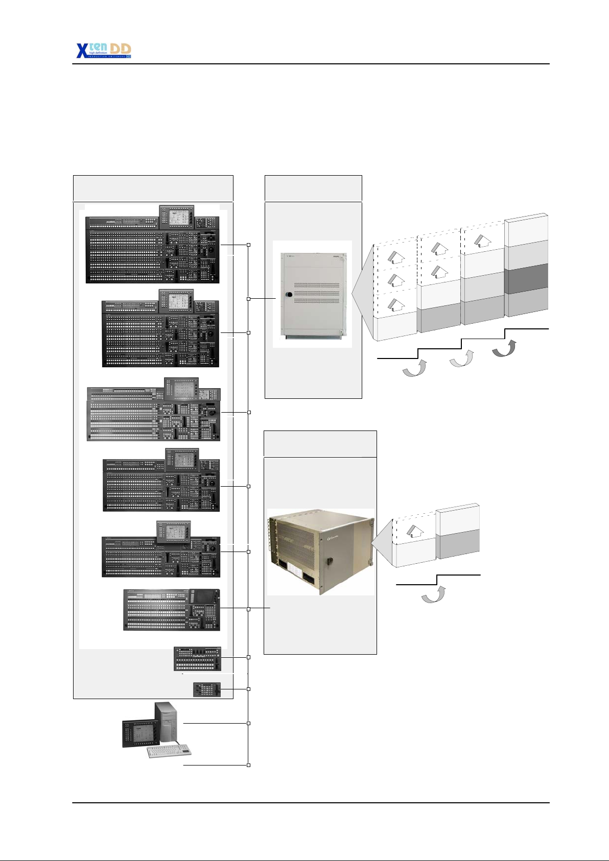
1.1 OVERVIEW HD XtenDD FAMILY
Configuration Overview
1. General
RPS35-4LX(32)
RPS35-4L
RPS35-3/32
RPS35-3
RPS35-x Basic Mainframe
++
Small Mainframe
SH-2-BM
1 M/E + P/P
Upgrade 1
=
M/E 1
P/P
HD35
Upgrade 2
Options
SH-1-BM
M/E 1
1 M/E
Mainframe Configurations
SH-3-BM
M/E 1
M/E 2
P/P
2 M/E + P/P
Upgrade 3
SH-4-BM
M/E 1
M/E 2
M/E 3
P/P
3 M/E + P/P
RPS35-2
RPS35-2/S
DD35 GUI PC *
Service PC
RSAT2 *
RSAT1 *
LAN
SH-2S-BM
SH-1S-BM
M/E 1
M/E 1
1 M/E
Small Mainframe Configurations / Upgrade
*Note:
For more details there are separate manuals available.
They can be ordered under the order numbers:
DD35 GUI PC RU 0063, 0 212 247 500
RSAT1
RSAT2
RU 0061, 0 212 174 600
RU 0065, 0 351 763 000
P/P
1 M/E + P/P
Upgrade 1
Planning and Installation - Rev. 3 / 04.2005
1 - 1
Page 9

1. General
1.2 DIGITAL HD PRODUCTION SWITCHER
1.2.1 KEY FEATURES
D 1.5 Gb/s video processing
D Selectable picture format
D 1, 2, 3 and 4 M/E versions with two mainframetypes
D 5 layers per M/E with 3 keyers and 2 background generators
D 90 inputs
D 36 outputs
D Integrated 2D DVE effects + RAM Recorder
D Machine Control interfaces to major Digital Disk Recorders (DDRs), servers,
laser disks and Video Tape Recorders (VTRs)
D Name-Follow-Video intelligent Router interface
D Full control interoperability with SDTV equipment
D Two compact mainframes types and low power consumption
1.2.2 COMMANDING CREATIVE POWER ... INNOVATING YOUR IMAGE
The HD XtenDD family is a new and exciting Production Switcher bringing creative
power to the heart of your High Definition (HD) production facility. This new product
is based on the user friendly and flexible DD35 series production switcher. The HD
XtenDD’s new electronic architecture has the capacity expand to ninety inputs and
twenty auxiliary outputs. This powerful combination ensures that even the most advanced HD production tasks can be achieved quickly with a minimum learning
curve.
Typical of the many stunning features is the Dyna Chrome TM Chroma Key. The
enhanced HD version now provides breath-taking levels of realism, delivering outstanding production value.
The HD XtenDD is not just a production switcher, it is your total production control
center. The system incorporates interfaces to major production peripherals putting
you in control of the entire production with remarkable simplicity.
Whatever your budget or production demands, the scalability of the HD XtenDD
allows you to adapt it to your precise needs. Guaranteed to be hassle free, it is
founded on the experience gained from over 1,200 THOMSON DD-series digital
production switchers in use around the globe with over 8 years of leadership in the
design of HD broadcast equipment.
1 - 2
Planning and Installation - Rev. 3 / 04.2005
Page 10

1.2.3 UNLIMITED CUSTOM SOLUTIONS
Recognizing that every user has different requirements, the modular architecture
of the THOMSON HD XtenDD allows you to configure the switcher to your precise
needs and budget without having to pay for unnecessary features.
The switcher is designed to accept additional modules which, as they become
available, will enable you to enhance your system with new features. Furthermore,
the resolution independence gives you the assurance that you can produce on any
of the current HD formats.
1.2.4 POWER NOT COMPLEXITY
With the substantial number of inputs and auxiliary outputs, the need to rely on external routing becomes minimized. This improves your operation by assuring frame
accuracy and synchronization of events.
With the capacity of 90 inputs, 20 auxiliary buses outputs, and 4 dedicated output
per M/E, there is virtually no job that is beyond the power of the THOMSON HD
XtenDD.
The Integrated Machine Control feature focuses the action to where it should be
... right at your finger - tips ... eliminating the need to move away from the production
switcher control panel. Without the need for a dedicated operator for every piece
of equipment, the technical director can be at the very center of activity, with full
control of the action.
1. General
1.2.5 NETWORKING YOUR RESOURCES
THOMSON traditional operation flexibility is the nucleus of the HD XtenDD, offering
virtually unlimited networking possibilities. Resources may be shared, combined
or remoted almost without limitation.
This flexibility maximizes the value of installed equipment by allowing unused resources to be reassigned to other users or tasks. Capabilities can range from enabling remote access (typically to allow on site rehearsal), or sharing one mixer between several users (two M/Es could be switching a show live while another M/E
is editing an off line interview).
This system flexibility will eventually lead to simultaneous HD and SD production
for simulcasts. All with a single panel, a single operator, and without additional cost.
1.2.6 PICTURE QUALITY AND FLEXIBILITY
The concept of the HD XtenDD is made possible by THOMSON powerful M/Es,
existing in several configurations; from a single M/E, to four full featured M/Es. This
switcher establishes the foundation from which your creative talent can develop the
most sophisticated productions.
The internal key processing quality and flexibility provided within each M/E and
PGM/PST is particularly noteworthy. Dyna Chrome TM , THOMSON’ acclaimed
chromakey processor, has been further enhanced for high definition. Dyna Chrome
TM, combined with the precise auto set -up, guarantees realistic keying with speed
and repeatability.
Planning and Installation - Rev. 3 / 04.2005
1 - 3
Page 11

1. General
With it’s potential of 6 downstream keyers, the HD XtenDD simplifies the creation
of cascaded inserts or multiple versioned outputs. Now the complicated task of split
feeds with different program keys is a breeze. And with three keyers per M/E, the
only limit to image composition is your imagination.
1.2.7 MISSION CONTROL
The HD XtenDD shares the same control panel family as the intuitive and widely
accepted THOMSON DD35 series switchers. Their functions and layout are the result of close discussion with many Technical Directors, truly making these panels
”Designed by TD’s, manufactured by THOMSON”.
Simplicity is further enhanced by features such as button-per-function and Name
Follow Video TM. With a knob and a button for every control function, and mnemonics that clearly identify source names you can, every input and every feature is immediately available for ultimate confidence that the ”mission” will go as planned.
Further refinements, including those provided by the exceptional MaKE- Memo TM
Macros, increase productivity and creativity and eliminate the pressure that can
lead to mistakes. With THOMSON MaKE- Memo TM the most complex of sequences can be programmed and recalled from a single keystroke.
The Graphical User Interface (GUI) provides you with additional access to the
many features of the HD XtenDD. Yet at no time is the reliability of mission- critical
tasks ever compromised. The GUI computer is in addition to the switcher main
processors. In an emergency, the switcher can be operated from the GUI in the unlikely event of a control panel failure. On the other hand, the switcher is totally functional without the GUI. These are examples of the exceptional levels of security and
redundancy designed into the HD XtenDD.
1.2.8 AND IF THAT’S NOT ENOUGH ...
Every one of the feature enhancing accessories designed for the DD35 are also
available for the HD XtenDD. This includes programmable remote control panels,
button separators and many more. These accessories increase the ease of use
and open doors to more applications.
1 - 4
Planning and Installation - Rev. 3 / 04.2005
Page 12

1.3 PANEL OVERVIEW
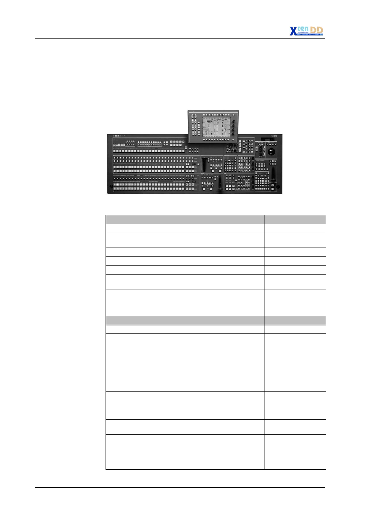
1.3.1 RPS35-2/S CONTROL PANEL
The production switcher panel RPS35-2/S with one mixing level M/E and one Program/Preset, as well as the touch screen display panel.
1. General
Fig. 101: Control Panel RPS35-2S
Panel Order number
RPS35-2S Control panel (OnAir normal lighting) 000 351 860 510
RPS35-2S-HL Control panel (OnAir high lighting) 000 351 862 510
Options Order number
RC 2453
RC 2456
RC 2351 Fanless Power Supply
RC 2376 Redundant Power Supply
RC 2380 Operating System Windows NT for PC 000 351 775 800
Input mnemonics for RPS 35-2S
P/P, MaKE, M/E 1 and AUX
Initial order only.
Input mnemonics for RPS35-2S
AUX, P/P, M/E 1 without
MaKE mnemonics
Initial order only.
Redundancy included
Initial order only.
(retrofitting possible)
000 212 265 311
000 212 265 610
000 351 772 100
000 351 774 600
Planning and Installation - Rev. 3 / 04.2005
1 - 5
Page 13
1. General
1.3.2 RPS35-2 CONTROL PANEL SET
The production switcher panel set RPS35-2 comprises the basic unit RPD35-2 with
one mixing level M/E and one Program/Preset, as well as the stand-alone display
panel RPV35-4TS.
The mnemonics for P/P and Make Memo Aux are standard.
Fig. 102: Control panel set RPS35-2
Panel Order number
RPS35-2 Control panel set
(OnAir normal lighting) including:
RPD35-2 Basic panel 000 351 861 810
RPV35-4TS Display panel 000 351 852 010
RPS35-2-HL Control panel set
(OnAir highlighting) including:
RPD35-2-HL Basic panel 000 351 863 210
RPV35-4TS Display panel 000 351 852 010
Options Order number
RC 2396 RPV mounting frame
used to mount the RPV display panel
onto the base panel
RC 2362 Input mnemonics extension
Initial order only.
RC 2351 Fanless Power Supply
Redundancy included
Initial order only.
RC 2148 Emergency Hard Disk Drive IDE, min.
2 GB. Must be order initially together
with basic panel.
Operating Software pre-configured.
RC 2376 Redundant Power Supply
(retrofitting possible)
RC 2380 Operating System Windows NT for PC 000 351 775 800
000 351 860 410
000 351 862 410
000 351 777 410
000 351 773 200
000 351 772 100
000 351 745 000
000 351 774 600
1 - 6
RC 2397 Stand tiltable for display panel 000 351 777 510
Planning and Installation - Rev. 3 / 04.2005
Page 14
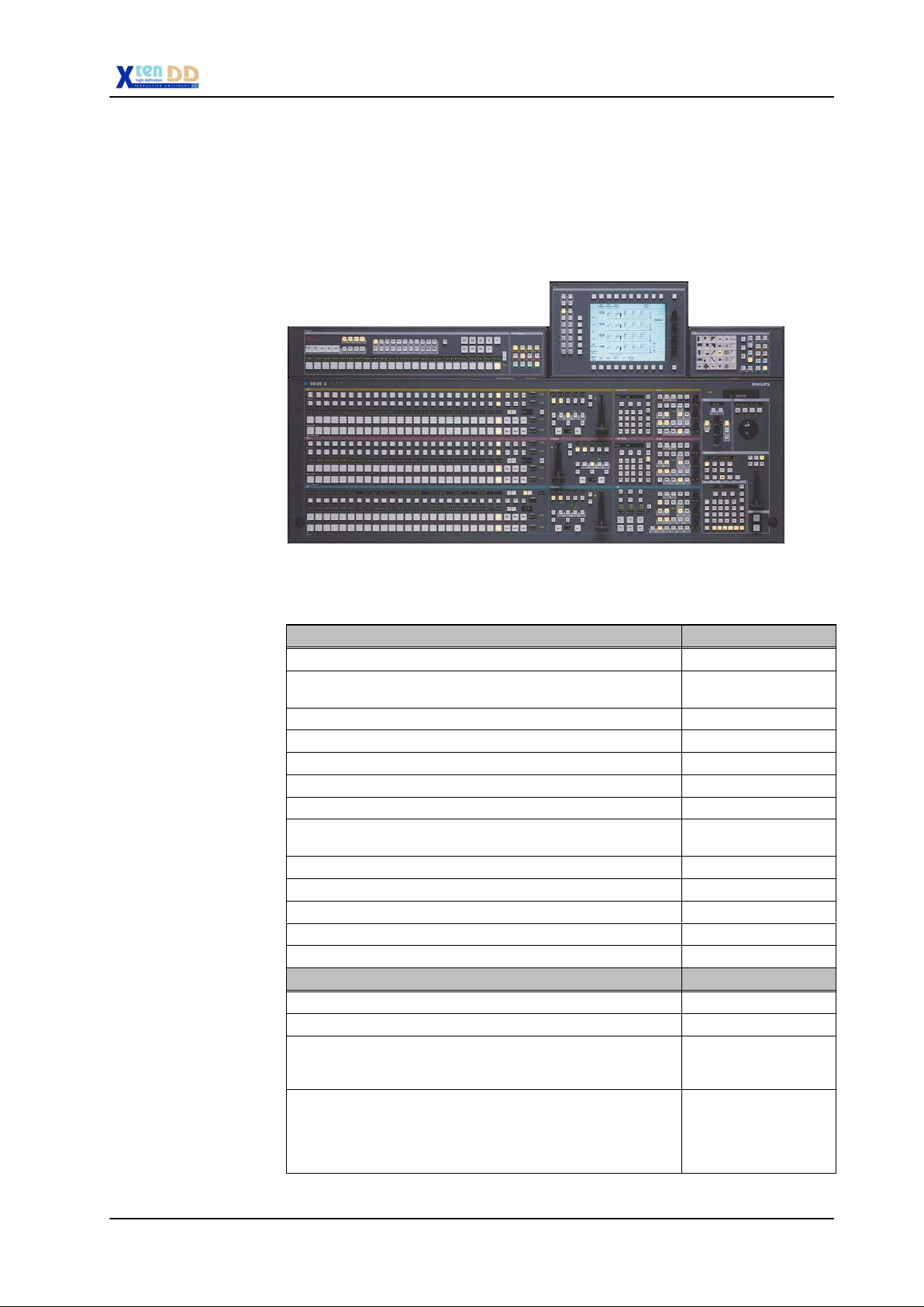
1.3.3 RPS35-3/24 CONTROL PANEL SET
The production switcher panel set RPS35-3/24 comprises the RPD35-3/24 with
two mixing levels M/E and one Program/Preset, the display panel RPV35-4TS, the
wipe panel RPW35-3/-4 and the aux panel RPA35-3/24.
All mnemonics are standard.
1. General
Fig. 103: Control panel set RPS35-3
Panel Order number
RPS35-3/24 Control panel set
(OnAir normal lighting) including:
RPD35-3/24 Basic panel 000 351 861 410
RPV35-4TS Display panel 000 351 852 010
RPA35-3/24 Aux panel 000 351 861 510
RPW35-3/-4 Wipe panel 000 351 861 710
RPS35-3/24-HL Control panel set (OnAir highlighting)
including:
RPD35-3/24-HL Basic panel 000 351 863 010
RPV35-4TS Display panel 000 351 852 010
RPA35-3/24-HL Aux panel 000 351 863 110
RPW35-3/-4 Wipe panel 000 351 861 710
Options Order number
000 351 860 310
000 351 862 310
RC 2360 Mounting frame set 000 351 773 000
RC 2351 Fanless Power Supply
RC 2214 Detachment cables (2.5 m) AUX or
Planning and Installation - Rev. 3 / 04.2005
000 351 772 100
Redundancy included
Initial order only.
000 351 747 000
Wipe.
For AUX or Wipe the set must be ordered separatly
(usually 2x needed!)
1 - 7
Page 15

1. General
Options Order number
RC 2148 Emergency Hard Disk Drive IDE, min.
2 GB. Must be ordered initially together
with basic panel.
Operating Software pre-configured.
RC 2376 Redundant Power Supply
(retrofitting possible)
RC 2380 Operating System Windows NT for PC 000 351 775 800
000 351 745 000
000 351 774 600
1 - 8
Planning and Installation - Rev. 3 / 04.2005
Page 16
1.3.4 RPS35-3/32 CONTROL PANEL SET
The production switcher panel set RPS35-3/32 comprises the RPD35-3/32 with
two mixing levels M/E and one Program/Preset, the display panel RPV35-4TS, the
wipe panel RPW35-3/-4 and the aux panel RPA35-3/32.
The mnemonics for P/P, Make Memo and Aux are standard.
1. General
Fig. 104: Control panel set RPS35-3/32
Panel Order number
RPS35-3/32 Control panel set (OnAir highlighting)
including:
RPD35-3/32 Basic panel 000 351 845 010
RPV35-4TS Display panel 000 351 852 010
RPA35-3/32 Aux panel 000 351 862 810
RPW35-3/-4 Wipe panel 000 351 861 710
Options Order number
RC 2360 Mounting frame set 000 351 773 000
RC 2351 Fanless Power Supply
Initial order only.
RC 2214 Detachment cables (2.5 m) AUX or
Wipe.
For AUX or Wipe the set must be ordered separatly
(usually 2x needed!)
000 351 840 010
000 351 772 100
000 351 747 000
Planning and Installation - Rev. 3 / 04.2005
1 - 9
Page 17

1. General
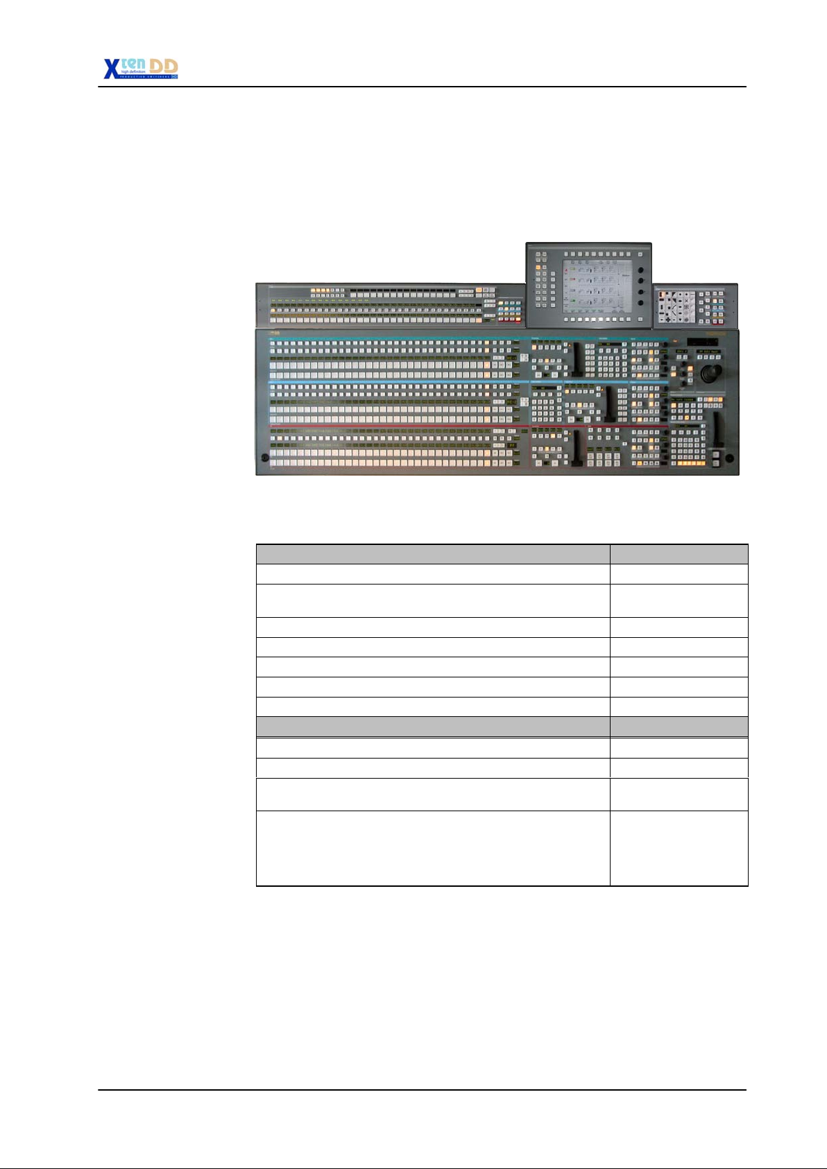
1.3.5 RPS35-4/32 CONTROL PANEL SET
The production switcher panel set RPS35-4/32 comprises the RPD35-4/32 with
three mixing levels M/E and one Program/Preset, the display panel RPV35-4TS,
the wipe panel RPW35-3/-4 and the aux panel RPA35-4/32.
The redundant power supply and input mnemonics are standard.
Fig. 105: Control panel set RPS35-4/32
There are two versions available:
1. Control Panel Set RPS35-4/32
OnAir normal lighting as all other DD35 family panels
2. Control Panel Set RPS35-4/32 HL
OnAir highlighting, where crosspoint buttons are high tallied when the bus is
OnAir and low tallied when not OnAir
Panel Order number
RPS35-4/32 Control panel set
(On Air normal lighting) including:
RPD35-4/32 Basic panel 000 351 855 000
RPV35-4TS Display panel 000 351 852 010
RPA35-4/32 Aux panel 000 351 853 000
RPW35-3/-4 Wipe panel 000 351 861 710
000 351 850 010
1 - 10
RPS35-4/32 HL Control panel set (OnAir highlighting)
including:
RPD35-4/32 HL Basic panel 000 351 862 610
RPV35-4TS Display panel 000 351 852 010
RPA35-4/32 HL Aux panel 000 351 862 810
RPW35-3/-4 Wipe panel 000 351 861 710
000 351 863 310
Planning and Installation - Rev. 3 / 04.2005
Page 18

1. General
Options Order number
RC 2840 Mounting frame set 000 351 854 000
RC 2148 Emergency Hard Disk Drive IDE, min.
2 GB. Must be ordered initially togehter
with basic panel.
Operating Software pre-configured.
RC 2351 Fanless Power Supply
Redundancy included
Initial order only.
RC 2376 Redundant Power Supply
(retrofitting possible)
RC 2380 Operating System Windows NT for PC 000 351 775 800
000 351 745 000
000 351 772 100
000 351 774 600
Planning and Installation - Rev. 3 / 04.2005
1 - 11
Page 19

1. General
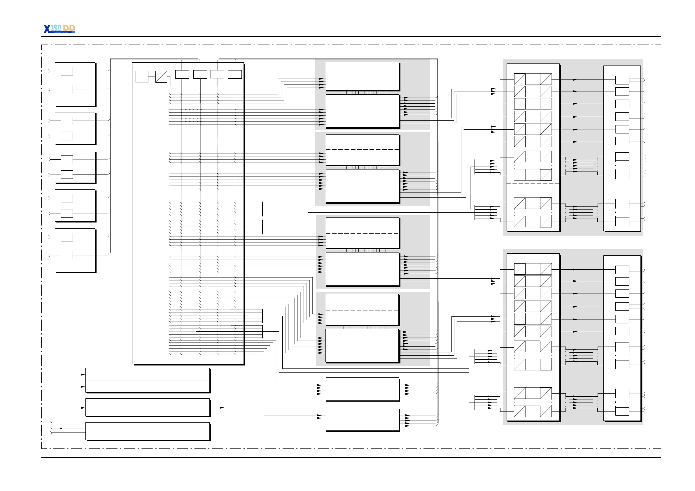
1.4 OVERALL BLOCK DIAGAMS
1.4.1 VIDEO SCHEMATICS SH 1/2/3/4 BM MAINFRAME
See block diagram on page 1- 13
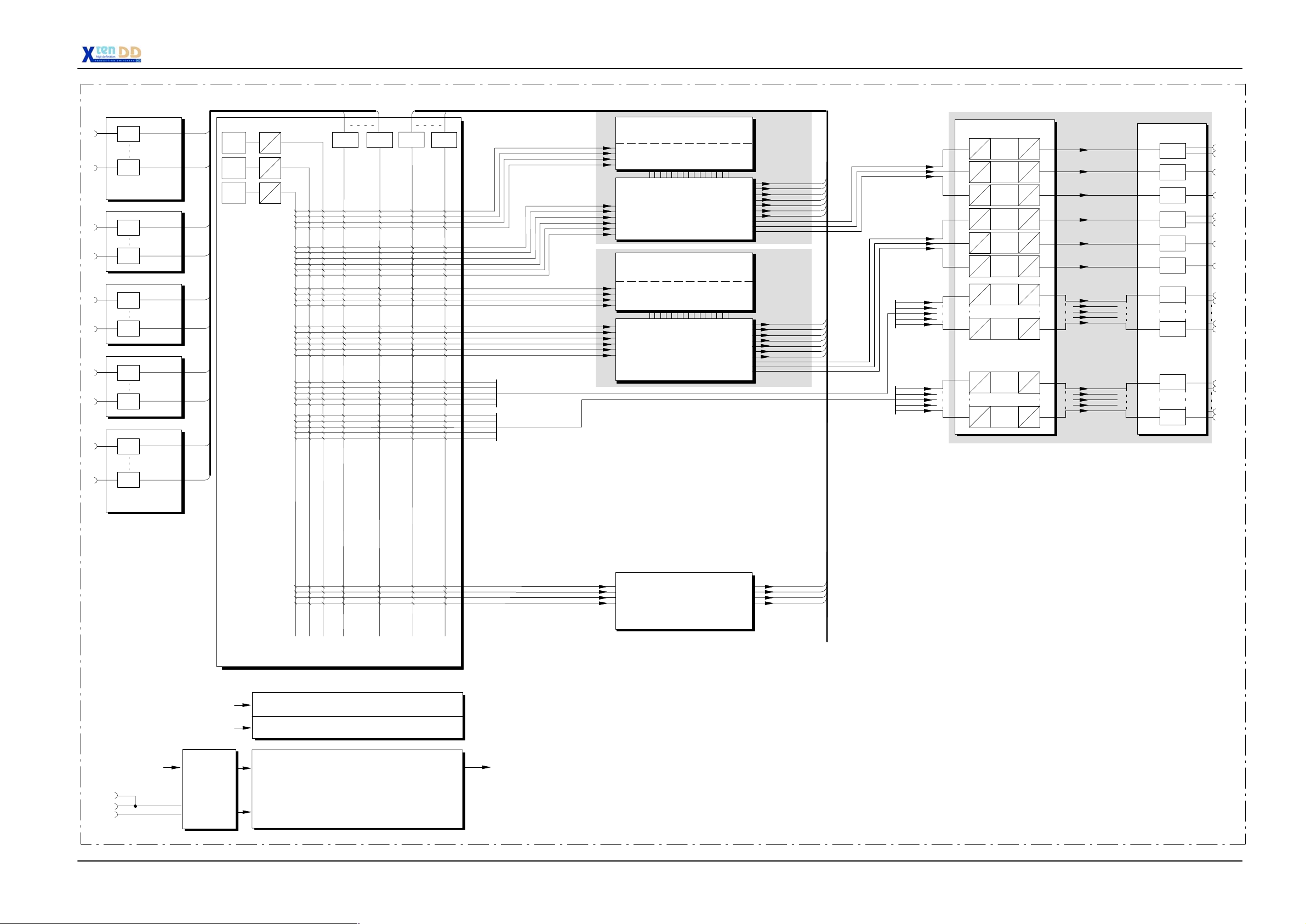
1.4.2 VIDEO SCHEMATICS SH 1/2S BM SMALL MAINFRAME
See block diagram on page 1- 15
1 - 12
Planning and Installation - Rev. 3 / 04.2005
Page 20

1. General
Planning and Installation - Rev. 3 / 04.2005
1 - 13
Page 21
1. General
1
18
19
36
37
54
55
72
73
EQUAL
EQUAL
INPUT MODULE
RY 3004
EQUAL
EQUAL
EQUAL
EQUAL
EQUAL
EQUAL
EQUAL
90 EXTERNAL90 EXTERNAL SIGNALS
WHITE
PAR
BUFFER BUFFER BUFFER
SER
BUFFER
37 INTERNAL SIGNALS
KEY 1
KEY 2
KEY 3
KEY 4
KEY FILL 1
KEY FILL 2
KEY FILL 3
DVE
PST
BGD
KEY 1
KEY 2
KEY 3
KEY 4
KEY FILL 1
KEY FILL 2
KEY FILL 3
DVE
PST
BGD
KEY 1
KEY 2
KEY 3
KEY 4
WIPE PROCESSOR
RY 3025 / RY 3026
KEY PROCESSOR
RY 3020
ME PROCESSOR
RY 3010
WIPE PROCESSOR
RY 3025 / RY 3026
KEY PROCESSOR
RY 3020
ME PROCESSOR
RY 3010
WIPE PROCESSOR
RY 3025 / RY 3026
KEY PROCESSOR
RY 3020
ME 1
PGM
PVW
CLEAN
UTIL A
UTIL B
UTIL C
KEY
ME PP
PGM
PVW
CLEAN
UTIL A
UTIL B
UTIL C
KEY
ME 2
PGM
PVW
CLEAN
PGM
PVW
CLEAN
AUX1
AUX2
AUX3
AUX4
AUX5
AUX6
AUX7
AUX8
AUX9
AUX10
OUTPUT PROCESSOR
RY 3030
LVDS
PAR
LVDS
PAR
LVDS
PAR
LVDS
PAR
LVDS
PAR
LVDS
PAR
SER
PAR
SER
PAR
OUTPUT PROCESSOR
EXTENSION RY 3035
SER
PAR
SER
PAR
AUTO
PHASE
AUTO
PHASE
AUTO
PHASE
AUTO
PHASE
AUTO
PHASE
AUTO
PHASE
5 Channel
AUTO
PHASE
AUTO
PHASE
5 Channel
AUTO
PHASE
AUTO
PHASE
PAR
SER
PAR
SER
PAR
SER
PAR
SER
PAR
SER
PAR
SER
PAR
SER
PAR
SER
PAR
SER
PAR
SER
OUTPUTS A
AUX1
AUX2
AUX3
AUX4
AUX5
AUX6
AUX7
AUX8
AUX9
AUX10
OUTPUT MODULE
RY 3005
BUFFER
BUFFER
BUFFER
BUFFER
BUFFER
BUFFER
BUFFER
BUFFER
BUFFER
BUFFER
PGM/23
PGM/24
PVW/21
CLEAN/22
PGM//27
PGM/28
PVW/25
CLEAN/26
1
5
6
10
90
EQUAL
INPUT MODULE
RY 3004
AC IN
AC IN
REMOTE
GPI IN
SERIAL IN
BLACK BURST
SER VID
INPUT PROCESSOR RY 3040
2x POWER SUPPLY RY 3009
2x POWER SUPPLY RY 3009 REDUNDANT
OPTION
CONTROLLER RY 3156
GENLOCK RY 3080
SERIALOUT
REMOTE
GPI OUT
TALLY
KEY 1
KEY 2
KEY 3
KEY 4
KEY FILL 1
KEY FILL 2
KEY FILL 3
DVE
PST
BGD
KEY FILL 1
KEY FILL 2
KEY FILL 3
DVE
PST
BGD
_
SRC 1
SPR
_
SRC 2
SPR
_
SRC 3
SPR
_
SPR
SRC 4
STORE 1
STORE 2
ME PROCESSOR
RY 3010
WIPE PROCESSOR
RY 3025 / RY 3026
KEY PROCESSOR
RY 3020
ME PROCESSOR
RY 3010
SPARE
RY 3060
STORE
RY 3050
PGM
PVW
CLEAN
UTIL A
UTIL B
UTIL C
KEY
ME 3
PGM
PVW
CLEAN
UTIL A
UTIL B
UTIL C
KEY
_
SPR
RET 1
_
RET 2
SPR
_
RET 3
SPR
SPR_RET 4
STO_KEY 1
STO_VID 1
STO_KEY 2
_
STO
VID 2
_
MAT
BGD
PGM
PVW
CLEAN
PGM
PVW
CLEAN
AUX11
AUX12
AUX13
AUX14
AUX15
AUX16
AUX17
AUX18
AUX19
AUX20
OUTPUT PROCESSOR
RY 3030
LVDS
PAR
LVDS
PAR
LVDS
PAR
LVDS
PAR
LVDS
PAR
LVDS
PAR
SER
PAR
SER
PAR
OUTPUT PROCESSOR
EXTENSION RY 3035
SER
PAR
SER
PAR
AUTO
PHASE
AUTO
PHASE
AUTO
PHASE
AUTO
PHASE
AUTO
PHASE
AUTO
PHASE
5 Channel
AUTO
PHASE
AUTO
PHASE
5 Channel
AUTO
PHASE
AUTO
PHASE
PAR
SER
PAR
SER
PAR
SER
PAR
SER
PAR
SER
PAR
SER
PAR
SER
PAR
SER
PAR
SER
PAR
SER
OUTPUTS B
AUX11
AUX12
AUX13
AUX14
AUX15
AUX16
AUX17
AUX18
AUX19
AUX20
OUTPUT MODULE
RY 3005
BUFFER
BUFFER
BUFFER
BUFFER
BUFFER
BUFFER
BUFFER
BUFFER
BUFFER
BUFFER
PGM/31
PGM/32
PVW/29
CLEAN/30
PGM/35
PGM/36
PVW/33
CLEAN/34
11
15
16
20
Planning and Installation - Rev. 3 / 04.2005
1 - 15
Page 22

1. General
1 - 16
Planning and Installation - Rev. 3 / 04.2005
Page 23
1. General
1
18
19
36
37
54
55
72
73
EQUAL
EQUAL
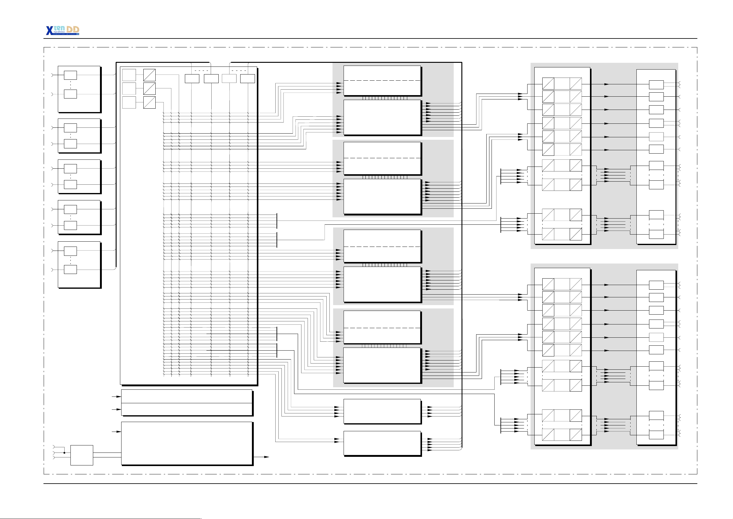
INPUT MODULE
RY 3140
Option
EQUAL
EQUAL
RC 3141
Option
EQUAL
EQUAL
RC 3142
Option
EQUAL
EQUAL
RC 3143
Option
EQUAL
90 EXTERNAL90 EXTERNAL SIGNALS
WHITE
COL 1
COL 2
PAR
SER
PAR
SER
PAR
SER
BUFFER BUFFER BUFFER
BUFFER
37 INTERNAL SIGNALS
KEY 1
KEY 2
KEY 3
KEY 4
KEY FILL 1
KEY FILL 2
KEY FILL 3
DVE
PST
BGD
KEY 1
KEY 2
KEY 3
KEY 4
KEY FILL 1
KEY FILL 2
KEY FILL 3
DVE
PST
BGD
KEY 1
KEY 2
KEY 3
KEY 4
WIPE PROCESSOR
RY 3025
KEY PROCESSOR
RY 3020
ME PROCESSOR
RY 3010
WIPE PROCESSOR
RY 3025
KEY PROCESSOR
RY 3020
ME PROCESSOR
RY 3010
WIPE PROCESSOR
RY 3025
KEY PROCESSOR
RY 3020
ME 1
PGM
PVW
CLEAN
UTIL A
UTIL B
UTIL C
KEY
ME PP
PGM
PVW
CLEAN
UTIL A
UTIL B
UTIL C
KEY
ME 2
PGM
PVW
CLEAN
PGM
PVW
CLEAN
AUX1
AUX2
AUX3
AUX4
AUX5
AUX6
AUX7
AUX8
AUX9
AUX10
OUTPUT PROCESSOR
RY 3031
LVDS
PAR
LVDS
PAR
LVDS
PAR
LVDS
PAR
LVDS
PAR
LVDS
PAR
SER
PAR
SER
PAR
SER
PAR
SER
PAR
AUTO
PHASE
AUTO
PHASE
AUTO
PHASE
AUTO
PHASE
AUTO
PHASE
AUTO
PHASE
5 Channel
AUTO
PHASE
AUTO
PHASE
5 Channel
AUTO
PHASE
AUTO
PHASE
PAR
SER
PAR
SER
PAR
SER
PAR
SER
PAR
SER
PAR
SER
PAR
SER
PAR
SER
PAR
SER
PAR
SER
OUTPUTS A
AUX1
AUX2
AUX3
AUX4
AUX5
AUX6
AUX7
AUX8
AUX9
AUX10
OUTPUT MODULE
RY 3160
BUFFER
BUFFER
BUFFER
BUFFER
BUFFER
BUFFER
BUFFER
BUFFER
BUFFER
BUFFER
PGM/23
PGM/24
PVW/21
CLEAN/22
PGM//27
PGM/28
PVW/25
CLEAN/26
1
5
6
10
90
EQUAL
INPUT MODULE
RY 3144
VidRev
Module
RY 3008
AC IN
AC IN
REMOTE
GPI IN
SERIAL IN
BLACK BURST
SER VID
INPUT PROCESSOR RY 3442
2x POWER SUPPLY RY 3009
2x POWER SUPPLY RY 3009 REDUNDANT
OPTION
GENLOCK + CONTROLLER
RY 3490
SERIALOUT
REMOTE
GPI OUT
TALLY
KEY 1
KEY 2
KEY 3
KEY 4
KEY FILL 1
KEY FILL 2
KEY FILL 3
DVE
PST
BGD
KEY FILL 1
KEY FILL 2
KEY FILL 3
DVE
PST
BGD
_
SRC 1
SPR
_
SRC 2
SPR
_
SRC 3
SPR
_
SRC 4
SPR
STORE 1
STORE 2
ME PROCESSOR
RY 3010
WIPE PROCESSOR
RY 3025
KEY PROCESSOR
RY 3020
ME PROCESSOR
RY 3010
RAMREC RY 3050
Option
SPARE RY 3060
HD DVE PROCESSOR RY 3060
Option
PGM
PVW
CLEAN
UTIL A
UTIL B
UTIL C
KEY
ME 3
PGM
PVW
CLEAN
UTIL A
UTIL B
UTIL C
KEY
SPR_RET 1
_
RET 2
SPR
_
RET 3
SPR
_
RET 4
SPR
STO_KEY 1
STO_VID 1
STO_KEY 2
_
STO
VID 2
_
MAT
BGD
PGM
PVW
CLEAN
PGM
PVW
CLEAN
AUX11
AUX12
AUX13
AUX14
AUX15
AUX16
AUX17
AUX18
AUX19
AUX20
OUTPUT PROCESSOR
RY 3031
LVDS
PAR
LVDS
PAR
LVDS
PAR
LVDS
PAR
LVDS
PAR
LVDS
PAR
SER
PAR
SER
PAR
SER
PAR
SER
PAR
AUTO
PHASE
AUTO
PHASE
AUTO
PHASE
AUTO
PHASE
AUTO
PHASE
AUTO
PHASE
5 Channel
AUTO
PHASE
AUTO
PHASE
5 Channel
AUTO
PHASE
AUTO
PHASE
PAR
SER
PAR
SER
PAR
SER
PAR
SER
PAR
SER
PAR
SER
PAR
SER
PAR
SER
PAR
SER
PAR
SER
OUTPUTS B
AUX11
AUX12
AUX13
AUX14
AUX15
AUX16
AUX17
AUX18
AUX19
AUX20
OUTPUT MODULE
RY 3061
BUFFER
BUFFER
BUFFER
BUFFER
BUFFER
BUFFER
BUFFER
BUFFER
BUFFER
BUFFER
PGM/31
PGM/32
PVW/29
CLEAN/30
PGM/35
PGM/36
PVW/33
CLEAN/34
11
15
16
20
Planning and Installation - Rev. 3 / 04.2005
1 - 17
Page 24

1. General
1 - 18
Planning and Installation - Rev. 3 / 04.2005
Page 25

1. General
1
18
19
36
37
54
55
72
EQUAL
EQUAL
INPUT MODULE
RY 3603
EQUAL
EQUAL
EQUAL
EQUAL
EQUAL
EQUAL
90 EXTERNAL90 EXTERNAL SIGNALS
WHITE
PAR
BUFFER BUFFER BUFFER
SER
BUFFER
37 INTERNAL SIGNALS
KEY 1
KEY 2
KEY 3
KEY 4
KEY FILL 1
KEY FILL 2
KEY FILL 3
DVE
PST
BGD
KEY 1
KEY 2
KEY 3
KEY 4
KEY FILL 1
KEY FILL 2
KEY FILL 3
DVE
PST
BGD
WIPE PROCESSOR
RY 3025 / RY 3026
KEY PROCESSOR
RY 3020
ME PROCESSOR
RY 3010
WIPE PROCESSOR
RY 3025 / RY 3026
KEY PROCESSOR
RY 3020
ME PROCESSOR
RY 3010
ME 1
PGM
PVW
CLEAN
UTIL A
UTIL B
UTIL C
KEY
ME PP
PGM
PVW
CLEAN
UTIL A
UTIL B
UTIL C
KEY
PGM
PVW
CLEAN
PGM
PVW
CLEAN
AUX1
AUX2
AUX3
AUX4
AUX5
AUX6
AUX7
AUX8
AUX9
AUX10
OUTPUT PROCESSOR
RY 3031
LVDS
PAR
LVDS
PAR
LVDS
PAR
LVDS
PAR
LVDS
PAR
LVDS
PAR
SER
PAR
SER
PAR
OUTPUT PROCESSOR
EXTENSION RY 3035
SER
PAR
SER
PAR
AUTO
PHASE
AUTO
PHASE
AUTO
PHASE
AUTO
PHASE
AUTO
PHASE
AUTO
PHASE
5 Channel
AUTO
PHASE
AUTO
PHASE
5 Channel
AUTO
PHASE
AUTO
PHASE
PAR
SER
PAR
SER
PAR
SER
PAR
SER
PAR
SER
PAR
SER
PAR
SER
PAR
SER
PAR
SER
PAR
SER
OUTPUTS A
AUX1
AUX2
AUX3
AUX4
AUX5
AUX6
AUX7
AUX8
AUX9
AUX10
OUTPUT MODULE
RY 3604
BUFFER
BUFFER
BUFFER
BUFFER
BUFFER
BUFFER
BUFFER
BUFFER
BUFFER
BUFFER
PGM/23
PGM/24
PVW/21
CLEAN/22
PGM//27
PGM/28
PVW/25
CLEAN/26
1
5
6
10
73
90
EQUAL
EQUAL
INPUT MODULE
RY 3603
REMOTE
GPI IN
SERIAL IN
BLACK BURST
SER VID
AC IN
AC IN
CONTROL
MODULE
RY 3605
INPUT PROCESSOR RY 3641
POWER SUPPLY UNIT RC 3406
REDUNDANT
POWER SUPPLY UNIT RC 3406
CONTROLLER RY 3156
GENLOCK RY 3080
SERIALOUT
REMOTE
GPI OUT
TALLY
SPR
SPR
SPR
SPR
_
SRC 1
_
SRC 2
_
SRC 3
_
SRC 4
RAM RECORDER
RY 3050
OPTION
SPR_RET 1
_
RET 2
SPR
_
RET 3
SPR
_
RET 4
SPR
Planning and Installation - Rev. 3 / 04.2005
1 - 19
Page 26

1. General
1 - 20
Planning and Installation - Rev. 3 / 04.2005
Page 27
1. General
1
18
19
36
37
54
55
72
73
EQUAL
EQUAL
INPUT MODULE
RC 3610
Option
EQUAL
EQUAL
RC 3611
Option
EQUAL
EQUAL
RC 3612
Option
EQUAL
EQUAL
RC 3613
Option
EQUAL
90 EXTERNAL90 EXTERNAL SIGNALS
WHITE
COL 1
COL 2
PAR
PAR
PAR
SER
SER
SER
BUFFER BUFFER BUFFER
BUFFER
37 INTERNAL SIGNALS
KEY 1
KEY 2
KEY 3
KEY 4
KEY FILL 1
KEY FILL 2
KEY FILL 3
DVE
PST
BGD
KEY 1
KEY 2
KEY 3
KEY 4
KEY FILL 1
KEY FILL 2
KEY FILL 3
DVE
PST
BGD
WIPE PROCESSOR
RY 3025
KEY PROCESSOR
RY 3020
ME PROCESSOR
RY 3010
WIPE PROCESSOR
RY 3025
KEY PROCESSOR
RY 3020
ME PROCESSOR
RY 3010
ME 1
PGM
PVW
CLEAN
UTIL A
UTIL B
UTIL C
KEY
ME PP
PGM
PVW
CLEAN
UTIL A
UTIL B
UTIL C
KEY
PGM
PVW
CLEAN
PGM
PVW
CLEAN
AUX1
AUX2
AUX3
AUX4
AUX5
AUX6
AUX7
AUX8
AUX9
AUX10
OUTPUT PROCESSOR
RY 3031
LVDS
PAR
LVDS
PAR
LVDS
PAR
LVDS
PAR
LVDS
PAR
LVDS
PAR
SER
PAR
SER
PAR
SER
PAR
SER
PAR
AUTO
PHASE
AUTO
PHASE
AUTO
PHASE
AUTO
PHASE
AUTO
PHASE
AUTO
PHASE
5 Channel
AUTO
PHASE
AUTO
PHASE
5 Channel
AUTO
PHASE
AUTO
PHASE
PAR
SER
PAR
SER
PAR
SER
PAR
SER
PAR
SER
PAR
SER
PAR
SER
PAR
SER
PAR
SER
PAR
SER
OUTPUTS A
AUX1
AUX2
AUX3
AUX4
AUX5
AUX6
AUX7
AUX8
AUX9
AUX10
OUTPUT MODULE
RY 3620
BUFFER
BUFFER
BUFFER
BUFFER
BUFFER
BUFFER
BUFFER
BUFFER
BUFFER
BUFFER
PGM/23
PGM/24
PVW/21
CLEAN/22
PGM//27
PGM/28
PVW/25
CLEAN/26
1
5
6
10
90
EQUAL
INPUT MODULE
RY 3614
REMOTE
GPI IN
SERIAL IN
BLACK BURST
SER VID
AC IN
AC IN
CONTROL
MODULE
RC 3630
Option
INPUT PROCESSOR RY 3442
POWER SUPPLY UNIT RC 3470
REDUNDANT
POWER SUPPLY UNIT RC 3470
GENLOCK + CONTROLLER
RY 3490
SERIALOUT
REMOTE
GPI OUT
TALLY
SPR
SPR
SPR
SPR
_
SRC 1
_
SRC 2
_
SRC 3
_
SRC 4
RAMREC RY 3050
Option
OR
FX RY 3060
Option
SPR_RET 1
_
SPR
RET 2
_
SPR
RET 3
_
RET 4
SPR
Planning and Installation - Rev. 3 / 04.2005
1 - 21
Page 28

1. General
1 - 22
Planning and Installation - Rev. 3 / 04.2005
Page 29

2. TECHNICAL DATA
2.1 MAINFRAME
2.1.1 INPUTS
Number & format Up to 90 inputs
2. Technical Data
10 bit, Serial component
according to SMPTE 292M (DSC), 1.5Gbit/s
Autophasing range: >
Asynchronous signals: switchable
Reference: tri- level Sync or DSC in (SMPTE 292M)
Return loss reference up to 1.5GHz >
Cable lengh max 80 m (high quality coax cable Belton 1694A)
2.1.2 OUTPUTS
Number & format 10 bit, Serial component
2.1.3 VIDEO SYSTEM DATA
HD standards 1080x50i
0.5 line dependent on standard
-10dB
according to SMPTE 292M (DSC), 1.5Gbit/s
up to 20 Aux Busses
Per M/E:
2x Program Video,
1x Preview, and
1x Clean Feed
1080x59.94i
1080x60i
1080x23fs
1080x24fs
1080x25fs
1080x29fs
1080x30fs
1080x23p
1080x24p
1080x25p
1080x29p
1080x30p
720x50p in preparation
720x59.94p
720x60p,
Planning and Installation - Rev. 3 / 04.2005
2 - 1
Page 30

2. Technical Data
Aspect ratio: 16:9
Overall Input/
PGM output delay: < 0.5 line dependent on standard
Blanking: switchable:
2.1.4 POWER SUPPLY MAINFRAME
Line voltage: 200 V to 240 V AC $10 % (SH- 1/2/3/4- BM)
Line current: 13 A max
Line frequency: 50 Hz / 60 Hz $5 %
Power Consumption: max. 1200W (SH -1/2/3/4 -BM)
Touch (leakage) currents: < 2.5 mA (for each power supply)
transparent for background signal or blanked
100 V to 240 V AC $10 % (SH-1/2S- BM)
max. 700 W (SH- 1/2S- BM)
2.1.5 MECHANICAL DATA SH- 1/2/3/4 - BM STANDARD MAINFRAME
)
Dimensions: 19” rackframe, 12 + 1
*
RU high
Hight 533 mm (20.98”)
Width 483 mm (19”)
Depht 554 mm (21.8”)
)
*
1 RU under the electronics box has to be
left free for ventilation, security tube
and slide-in rails
Weight: < 154 lbs / 70 kg.
2.1.6 MECHANICAL DATA SH- 1/2S- BM SMALL MAINFRAME
Dimensions: 19” rackframe, 7 RU high
Hight 310 mm (12.2”)
Width 483 mm (19”)
Depht 508 mm (20”)
Weight: < 77 lbs / 35 kg (incl. all options)
2.1.7 ENVIRONMENTAL DATA
Storage temperature: -4°F to +158°F
Operating Temperature: +41
Relative humidity: <= 80% non- condensing
2 - 2
(-20°C to +70°C)
°
F to +95°F
°
C to +35°C)
(+5
Planning and Installation - Rev. 3 / 04.2005
Page 31

2.1.8 INTERFACE DATA
• 8+6 intern GPI, 8+6 intern GPO
• 9 Serial ports (Mainframe) D-Sub sockets 9-pin, female, RS 485/422,
• 1 RS485/RS422-Serial Extension, D-Sub socket 9-pin, female
• 5 Serial ports (Mainframe)
2. Technical Data
GPI: Opto coupler, dry contact or active in, (8 Mainframe, 6 Panel) max. 40mA.
GPO: Silicon switches, potential free, 40V/0.3A.
D-Sub socket 50-pin, female (panel 25-pin, female) 40 V, 0.5 A
38.4 kbd max.
Tributary-Bus Controller mode switchable, for DVE, Edit Systems, ext DSK,
port for serial Tally & more optional Tallies: CH1 (r), CH2 (g), Preset (y),
GP I/Os- support of up to 68 ext. Tally Outputs
- support of up to 21 ext. Tally inputs
- further 40 GPI/GPO channels
2x D-Sub sockets 9-pin, female, RS 232C, 38.4 kbd max,
1x D-Sub socket 15-pin, female (Multi Port) with 3x RS 232C
• 3 Service ports, D-Sub sockets 9-pin, female, RS 232C
(2x Mainframe, 1x Panel)
• 2 Modem ports, D-Sub sockets 25-pin, female, RS 232C
(1x Mainframe, 1x Panel)
• LAN (mainframe), 1 BNC (remote), cheapernet,
50 ohms, 150 m, with repeater max. 2.5 km,
can be looped through with a T-type connector
• LAN (control panel), 1 BNC, cheapernet,
50 ohms, 150 m, with repeater max. 2.5 km,
can be looped through with a T-type connector
• LAN (panel PC), 1 BNC , cheapernet,
50 ohms, 150 m, with repeater max. 2.5 km,
can be looped through with a T-type connector
• 4 Serial ports (Control Panel), D-sub sockets 9-pin, female, RS485/422C
for UMDs or Aux extensions
• 2 Serial ports (Control Panel), 2x D-sub sockets 9-pin, female,
RS232C, 38.4 kbd
• PC Communication Ports (several) VGA Port, LCD, PS/2, RS 232C
Planning and Installation - Rev. 3 / 04.2005
2 - 3
Page 32

2. Technical Data
2.2 CONTROL PANELS
2.2.1 INTEGRATED SIDE PANEL PC
• Industry PC board
• RPV-Panel connectors:
RPS35-4 connected via RS232 Port and TFT connector
RPS35-2 / RPS35-3 connected via Panel Link port
• Serial Ports RS232:
RPS35-4 with 2x RS232 serial communication ports for RPV
and peripheral devices
RPS35-2 and RPS35-3 with 1x RS232 serial communication ports
for peripheral devices
• 1 PC-Keyboard Connector PS/2- type
• 1 Parallel Port (for Printer)
• 10.4” Color active matrix TFT LCD Display
• PC-Board communication via LAN- Adapter
• Built-in floppy drive & hard disk
• Suited for adaption of peripheral devices
(Tablet, Mouse, Pen, TouchScreen)
• VGA port D-Sub socket 15-pin, male
2.2.2 POWER SUPPLY CONTROL PANELS
• 1 power modules LPQ 250 standard
• 1 redundant power module LPQ 250 optional
• Line voltage 100 V to 240 V AC $10 %, autosense
• Line current 2.5 A max
• Line frequency 50 Hz to 60 Hz
• Active power factor connection PFC
• Output voltages +5 V, + 12 V, - 12 V
• Power connection connector type IEC 320, VDE 0625 Part 1
• Safety UL 1950 /CSA 22.2 No. 950
• Power consumption control panels < 250 W
2 - 4
Planning and Installation - Rev. 3 / 04.2005
Page 33

3. INSTALLING MAINFRAME
3.1 UNPACKING
Your equipment may be shipped in several different boxes, depending upon order
size and configuration.
Check the contents of each box against the packing list to ensure your order is complete. If equipment is missing or damaged, contact the shipping company immediately.
3. Installing Mainframes
Box 1 - Mainframe
Box 1 contents the following parts:
D Mainframe (equipped with ordered option boards)
D Power cord (standard)
D Power cord (redundant power supply, if ordered)
D Accessory pack 002 212 240 011:
BNC T-type connector, 50 ohms
BNC terminator, 50 ohms
BNC terminator, 50 ohms, with ground connector
BNC terminator, 75 ohms
10 Fuses M 10/250E
10 Fuses UL T 0.8/250B
Mounting set
Earth wire
Planning and Installation - Rev. 3 / 04.2005
3 - 1
Page 34

3. Installing Mainframes
3.2 MECHANICAL DIMENSIONS
3.2.1 MAINFRAME SH - 1/2/3/4 - BM
The mainframe of the switcher is located in a closed 19-inch frame which houses
the individual plug-in cards of the video and control electronics as well as the power
supply units.
17.3” = 440 mm
12 RU
533 mm
19” = 483 mm
1RU
43 mm
18.6” = 474 mm
21.8” = 554 mm
3 - 2
Planning and Installation - Rev. 3 / 04.2005
Page 35

3.2.2 SMALL MAINFRAME SH -1/2S -BM
The mainframe of the switcher is located in a closed 19-inch frame which houses
the individual plug-in cards of the video and control electronics as well as the power
supply units.
3. Installing Mainframes
17.6” = 447 mm
7RU
12.2”
310.3 mm
19” = 483 mm
20” = 508 mm
21,3” = 540 mm
(incl. connectors)
Planning and Installation - Rev. 3 / 04.2005
3 - 3
Page 36

3. Installing Mainframes
3.3 INSTALLATION IN A CABINET
General rack mounting instructions
D The maximum ambient temperature for this unit is 40°C.
D Installing the unit in a closed or multi-unit rack assembly, together with other
units could increase the maximum ambient for this unit.
D If the unit is installed in a rack, no ventilation openings should be blocked or
otherwise covered. Ensure a sufficient amount of airflow.
D Mounting of the unit in the rack should be such that a hazardous condition is
not achieved due to uneven mechanical loading.
D When connecting the unit to the supply circuit be sure that the supply circuit of
the rack is not overloaded. For ratings see chapter Technical Data.
D The unit must be grounded to a good earth ground using a wire as specified
by the local electrical code. This wire is attached to the protective earth connector on the rear. For details refer to chapter General Grounding Requirements.
D When connecting the unit in a closed or multi-unit rack assembly together with
other units be sure that the summation of the touch (leakage) currents for each
power supply circuit is not higher than 3.5 mA . In this case the rack must be
permanently connected with an earth terminal. Earth connection is essential
before connecting supply voltage! For details see chapter Technical Data.
For installation, Thomson optionally provides a 19-inch cabinet with recommended
mounting accessories. When using cabinets of other manufacturers, observe the
respective mounting instructions.
Note: For installation into a DIN cabinet, adapter pieces of the respec-
tive cabinet manufacturer have to be mounted on both sides of
the lateral fastening flanges.
For relieving the front mounting brackets, the mainframe has also to be supported
in the rear part of the frame. The corresponding mounting parts can be obtained
as accessories from the manufacturer of the cabinet-type rack.
CAUTION
Do not use the rack ears as primary mounting means.
WARNING
3 - 4
With the standard modules installed, the SH - 1/2/3/4 -BM mainframe weights
70 kg (154 lbs). During installation and until secured in the rack, use an appropriate lifting device to lift and support the mainframe. Failure to follow
this precaution can result in injury to personnel and damage to equipment.
Planning and Installation - Rev. 3 / 04.2005
Page 37

3.4 VENTILATION
3.4.1 MAINFRAME SH -1/2/3/4 -BM
The ambient temperature during operation must not fall below + 5 °C or exceed
+ 35 °C (41 °F to 95°F). Optimum operation is ensured at an ambient temperature
of 20 °C.
For ventilation of the mainframe, 3 fans are provided in the upper part. These blowers serve to support air circulation in the unit and to lead the heated air into the
room. The air supply is made from the front and from the bottom. Fans blow the
heated air into the rear part of the cabinet.
In order to ensure continuous air circulation, make sure that the air slots in
the bottom part of the unit are not covered when mounting the mainframe.
3. Installing Mainframes
Exhaust air exits from the rear at top
Note: The door is an integral part of the cooling airflow design.
For proper cooling keep the door closed during normal
operation.
Cleaning the
Air filter
Planning and Installation - Rev. 3 / 04.2005
Ensure that the air filter fitted to the SH- 1/2/3/4- BM mainframe front door is cleaned periodically with a vacuum cleaner to ensure the adequate cooling. The color
of the filter (normally white) can be used as a guide to their condition.
Air intake (both sides and front)
3 - 5
Page 38

3. Installing Mainframes
3.4.2 SMALL MAINFRAME SH-1/2S BM
The ambient temperature during operation must not fall below + 5 °C or exceed
+ 40 °C (41 °F to 104°F). Optimum operation is ensured at an ambient temperature
of 20 °C.
The mainframe is ventilated by the fan unit (8 fans) being mounted at the left side
in the mainframe. The air is sucked in at the left side of the mainframe and is exhausted at the right side through the louvers. These fans serve to support air circulation in the unit and to lead the heated air into the room. The power supplies in
the lower part of the carrier are cooled by two internal fans. The air is sucked in at
the front and is let out through the louvers at the rear.
In order to ensure continuous air circulation, make sure that the air slots on
the left and right side and on the rear side of the unit are not covered when
mounting the mainframe.
Air intake
from the left side
Note: The door is an integral part of the cooling airflow design.
Exhaust air exits from
the right of the unit
For proper cooling keep the door closed during normal
operation.
3 - 6
Planning and Installation - Rev. 3 / 04.2005
Page 39

4. INSTALLING THE CONTROL PANELS
4.1 UNPACKING
Your equipment may be shipped in several different boxes, depending upon order
size and configuration.
Check the contents of each box against the packing list to ensure your order is
complete. If equipment is missing or damaged, contact the shipping company immediately.
4. Installing Control Panels
Box 2 - Control panel
Box 2 contents the following parts:
D Basic control panel
D Aux control panel module
D Display panel module
D Wipe control panel
D Power cord (standard)
D Power cord (redundant power supply, if ordered)
D 7 control cable 1.2 m or 2.5 m (if ordered)
D Cheapernet cable 20 m
D Cheapernet cable 1 m
D Customer’s manual
D Final test report with Quality certification
Planning and Installation - Rev. 3 / 04.2005
4 - 1
Page 40

4. Installing Control Panels
D Software package:
Mouse
CD-ROM HD35 software
CD-ROM Intel PII Bus Master Device Drivers
CD-ROMs Microsoft Windows 95 package
3.5” Diskette Microsoft Setup Boot Disk
3.5” Diskette Philips Ethernet Link Driver
3.5” Diskettes Philips WGE10 Utilities (2 disks)
Motherboard documentation
D Accessory pack 002 351 740 051:
Locking tool for sub-panels
Panel keys
BNC T-type connector, 50 ohms
BNC terminator, 50 ohms
Pushbutton inlay sets
2 Fuses ATC-7 1/2
2 Fuses ATC-5
12 caps for sub-panels locking holes
Box 3 - All-in-one mounting frame (optional)
Box 3 contents the following parts:
D All-in-one mounting frame
D Fastening screws
4.2 MECHANICAL DIMENSIONS
The figures on the next pages shows all mechanical dimensions of the control panels which are relevant for installation in a master control desk.
The size of the desk cutout is also indicated.
4 - 2
Planning and Installation - Rev. 3 / 04.2005
Page 41

4.2.1 RPS35-2/S CONTROL PANEL
FRONT
4. Installing Control Panels
1084
13
314.5
1
1058
43.3
1
13
LEFT
o
25
89
51.5
Keep free for cabling!
5
13
20
Please keep free for service working!
10
o
o
90
1 1
434
460
75
o
7
51.5
160
13
TOP
1080
1084
2112
ISO
460
456
11
Note!
All measurements are [mm].
Tolerance +/- 0,2
Planning and Installation - Rev. 3 / 04.2005
4 - 3
Page 42

4. Installing Control Panels
TOUCHSCREEN DISPLAY OF THE RPS35-2S PANEL
65 60
21.6328.08
M4
298.5
278.5
288
294
311.5
314.5
1.5
10.6139.35
152.87
81
0.8
9.8
160.58
44.5
1.3
4 - 4
Attention!
When separating the display from the control panel,
D the EMV protection is not ensured any longer (radiation is also possible via the cables)
D the ESD protection is not ensured any longer (damage to electronic components is possible)
D the UL and other permissions are not applicable any longer
D warrenty is not ensured any longer
Note!
All measurements are [mm].
Planning and Installation - Rev. 3 / 04.2005
Page 43

4.2.2 RPS35-2 CONTROL PANEL
Mechanical dimensions see next page.
4. Installing Control Panels
LEFTFRONT
51.5
o
105
160
TOP
1364
460
Keep free for cabling!
o
15
11
434
Note:
There are two possibilities of mounting Display Module RPV35-2.
3. Mounting the display module with the mounting frame outside the switcher
into the control desk or wall. See section 4.3.1 Single Module Mounting.
4. Stand-alone display with rigid stand.
The stand has to be mounted on the control panel in the place provided for this
purpose, between Aux and Wipe panel.
For mounting the stand, see the mounting drawing on the next page.
The associated mounting material will be delivered with the stand-alone display.
ISO
Planning and Installation - Rev. 3 / 04.2005
1386
1390
2
11
2
11
Note
All measurements are [mm].
Tolerance +/- 0,2
4 - 5
Page 44

4. Installing Control Panels
49
RPV35-2 Stand-Alone Display Panel
261
mounting plate
89.04
20.4
4 max
15.23
6.5
30
265
20
o
4 - 6
9
0
15
25
385
164.25
30
3
2
389
100
70
50
M5
75
85
100
Planning and Installation - Rev. 3 / 04.2005
Page 45

4.2.3 RPS35-3/24 CONTROL PANEL
4. Installing Control Panels
o
FRONT
TOP
1390
1364
3.5
238.2
141
o
100
LEFT
390724
3.5
270
258.4
max. 273
Keep free for cabling!
202.1
184.6
184
163.3
124
106
434
11
51.5
o
105
160
o
15
1386
1390
187.4
ISO
649
460
2
11
2
11
Note
All measurements are [mm].
Tolerance +/- 0,2
Planning and Installation - Rev. 3 / 04.2005
4 - 7
Page 46

4. Installing Control Panels
4.2.4 RPS35-3/32 CONTROL PANEL
192.5
FRONT
TOP
1602
1576
3.5
LEFT
649,5
390935
3.5
270
259
141
160
Option - Fanless Power Supply
189,55
Option - Mounting Frame
159,5 7,3
13
558
13
434
1598
1602
187.4
649
460
2
11
2
11
ISO
Note
All measurements are [mm].
Tolerance +/- 0.2
4 - 8
Planning and Installation - Rev. 3 / 04.2005
Page 47

4.2.5 RPS35-4/32 CONTROL PANEL
4. Installing Control Panels
o
192.5
FRONT
TOP
1602
1576
3.5
238.2
o
192.5
100
LEFT
390935
3.5
270
141
258.4
max. 273
Keep free for cabling!
202.1
184.6
184
163.3
124
106
570
11
51.5
o
105
196
o
15
1598
1602
187.4
ISO
785
596
2
11
2
11
Note
All measurements are [mm].
Tolerance +/- 0.2
Planning and Installation - Rev. 3 / 04.2005
4 - 9
Page 48

4. Installing Control Panels
4.2.6 DESK CUT OUT FOR RPS35-2/S
12
12
legend
Cut-out
module edge
1060
0
-1
Cut- out measurements
Note
All measurements are [mm].
12
12
0
-1
436
4 - 10
Planning and Installation - Rev. 3 / 04.2005
Page 49

4.2.7 DESK CUT OUT FOR RPS35-2
4. Installing Control Panels
12
legend
Cut-out
module edge
0
1366
-1
1390
Cut- out measurements
Note
All measurements are [mm].
12
0
-1
436
460
Planning and Installation - Rev. 3 / 04.2005
4 - 11
Page 50

4. Installing Control Panels
4.2.8 DESK CUT-OUTS FOR RPS35-3/24
143460
0
119
-1
436
701
725
-1
390
0
0
-1
23
22
17
270
246346
-1
0
0
-1
12
226
266
0
-1
649
625
4 - 12
12
12
legend
Cut-out
module edge
0
1366
-1
1390
Cut- out measurements for single module mounting
12
Cut- out measurements for panels with
”All-in-One” Mounting Frame RC 2360
Note
All measurements are [mm].
Planning and Installation - Rev. 3 / 04.2005
Page 51

4.2.9 DESK CUT-OUTS FOR RPS35-3/32
4. Installing Control Panels
195
460
0
0
171
436
-1
-1
911
935
-1
246
270
-1
0
0
-1
0
-1
119
226
143
266
0
-1
625
649
390
0
346
23
17
0
-1
22
12
12
legend
Planning and Installation - Rev. 3 / 04.2005
Cut-out
module edge
0
1578
-1
1602
Cut- out measurements for single module mounting
12
Cut- out measurements for panels with
”All-in-One” Mounting Frame RC 2840
Note
All measurements are [mm].
4 - 13
Page 52

4. Installing Control Panels
4.2.10 DESK CUT-OUTS FOR RPS35-4/32
195
596
0
0
171
572
-1
-1
911
935
-1
246
270
-1
0
0
-1
0
-1
119
226
143
266
0
-1
761
785
390
0
346
23
17
0
-1
22
4 - 14
12
12
legend
Cut-out
module edge
0
1578
-1
1602
Cut- out measurements for single module mounting
12
Cut- out measurements for panels with
”All-in-One” Mounting Frame RC 2840
Note
All measurements are [mm].
Planning and Installation - Rev. 3 / 04.2005
Page 53

4.2.11 REMOTE PANEL RSAT2
464
240
4. Installing Control Panels
58
25.8
7
176.7
439
482.6
19” Mounting Frame
12.5 215
190.5
114.5
265.9
6 Rack units
465.1
Planning and Installation - Rev. 3 / 04.2005
All dimensions are [ mm ]
4 - 15
Page 54

4. Installing Control Panels
4.2.12 DESK CUT-OUT FOR REMOTE PANEL RSAT2
Cut-out dimensions: 441 x 217 mm
4 - 16
Planning and Installation - Rev. 3 / 04.2005
Page 55

4.2.13 DESK CUT-OUT FOR SATELLIT PANEL RSAT1
4. Installing Control Panels
Cut-out dimensions: 245 x 118 mm
Planning and Installation - Rev. 3 / 04.2005
4 - 17
Page 56

4. Installing Control Panels
4 - 18
Planning and Installation - Rev. 3 / 04.2005
Page 57

4.3 INSTALLING PANELS
WARNING!
4. Installing Control Panels
With the standard modules installed, the
(110 lbs). During installation and until secured in the desk, use an appropriate
lifting device to lift and support the main panel. Failure to follow this precaution can result in injury to personnel and damage to equipment.
WARNING!
The control panels do not contain any control elements or switches required
for operation of the switcher. For this reason, the control panel should not
be opened by unauthorized persons and should always be locked.
The panel must be opened by authorized service personnel only!
Prior to opening the panel make sure that there are no objects on the panel,
such as pens, screwdrivers or other tools. When opening the panel, they
might fall into the device and cause disturbances.
Please close the control panel slowly. Do not let it drop!
CAUTION!
basic panel weights 50 kg
Control Panel hinges may not be adequate to hold panel in the open position
if mounted at more than 15 degrees.
ATTENTION!
RPD 35-2 display with rigid stand:
Please open the panel only to such an extend that the display will not be damaged at the slanted part of the desk!
RPD 35-2 Display with tiltable stand:
Prior to opening the panel, tilt the display as a precaution to the front!
Planning and Installation - Rev. 3 / 04.2005
4 - 19
Page 58

4. Installing Control Panels
4.3.1 SINGLE MODULE MOUNTING
NOTE!
There are two possibilities of mounting Display Module RPV35-2.
1. Mounting the display module with the mounting frame outside the switcher into
the control desk or wall. See below.
2. Stand-alone display with rigid stand.
The stand has to be mounted on the control panel in the place provided for this
purpose, between Aux and Wipe panel.
For mounting the stand, see the mounting drawing in chapter 4.2.2 RPS25-2
Control Panel.
The associated mounting material will be delivered with the stand-alone display.
D Trace careful the positions of each panel on the desk. The exact dimensions
of the main panel and the side panels you can find in section “Desk cut-outs”.
D Cut-out the openings in the desk.
D Unpack each individual piece.
ATTENTION!
Electrostatic sensitive devices. Observe the precautions for handling!
D Put in the mounting frame of the side panels. For fastening, bores are provided
in the frame of each mounting frame. The respective frame can be fastened
with countersunk wood screws with a diameter of 4 mm. The length of the screw
depends on the plate thickness of the desk. A set with mounting parts is included in the delivery of the switcher.
D Connect the flat cables into the corresponding plugs of the modules.
D Put in the side panel modules in in the mounting frames. By pressing, the mod-
ules engages independently. The locking mechanism can be removed by the
two release tools (in panel accessory pack). Therefore the module can be removed very simply from the mounting frame. After mounting the panels please
close all locking holes witch the plastic caps delivered in the accessory pack.
D Put in the main panel in the cutout. For fastening, bores are provided in the
frame. The frame can be fastened with countersunk wood screws with a diameter of 4 mm. The length of the screw depends on the plate thickness of the desk.
A set with mounting parts is included in the delivery of the switcher.
Depending upon cable routing and clearances, you may want to attach control
panel cabling before you lower the panel into the cutout.
4 - 20
Planning and Installation - Rev. 3 / 04.2005
Page 59

4.3.2 MOUNTING WITH “ALL-IN-ONE” MOUNTING FRAME
D Trace careful the position of panel on the desk. The exact dimensions of the
main panel and the side panels you can find in section “Desk cut-outs”.
D Cut-out the opening in the desk.
D Unpack each individual piece.
ATTENTION!
Electrostatic sensitive devices. Observe the precautions for handling!
D Mount the “All-in-one” mounting frame with the screws on the rear side of the
panel.
4. Installing Control Panels
Planning and Installation - Rev. 3 / 04.2005
4 - 21
Page 60

4. Installing Control Panels
D Put in the extended main panel in the cutout. For fastening, bores are provided
D Note for mounting the display side panel:
D Put in the mounting frame of the side panels. For fastening , bores are provided
D Connect the flat cables into the corresponding plugs of the modules.
D Put in the side panel modules in in the mounting frames. By pressing, the mod-
in the frame. The frame can be fastened with countersunk wood screws with
a diameter of 4 mm. The length of the screw depends on the plate thickness
of the desk. A set with mounting parts is included in the delivery of the switcher.
Connect the three cables first on the rear panel of the display side panel before
put in the display mounting frame in the the “All-in-one” mounting frame!
in the frame of each mounting frame. The respective frame can be fastened
with countersunk screws with a diameter of 4 mm. A set with mounting parts
is included in the delivery of the switcher.
ules engages independently. The locking mechanism can be removed by the
two release tools (in panel accessory pack). Therefore the module can be removed very simply from the mounting frame. After mounting the panels please
close all locking holes witch the plastic caps delivered in the accessory pack.
release
tools
D Depending upon cable routing and clearances, you may want to attach control
panel cabling before you lower the panel into the cutout.
4 - 22
Planning and Installation - Rev. 3 / 04.2005
Page 61

4.4 VENTILATION
During operation, the ambient temperature in the desk must not fall below 5 °C and
not exceed 35 °C.
For supply air and exhaust air, ventilation slots are provided in the lower control
panel part. In order to ensure continuous air circulation, make sure that the ventilation slots are not covered when mounting the control panel!
The control panel must not be mounted into closed desks!
Air intake
4. Installing Control Panels
Exhaust air exits
NOTE!
In RPS35-2S the fan is temperature controlled and works at a temperature
higher than 405 C.
Planning and Installation - Rev. 3 / 04.2005
4 - 23
Page 62

4. Installing Control Panels
4 - 24
Planning and Installation - Rev. 3 / 04.2005
Page 63

5. CONNECTION AND STARTUP
5.1 GROUNDING REQUIREMENTS
For grounding of the devices, the following three methods are
possible:
5. Connection and Startup
PE TE
Protective grounding
1. Grounding with the protective earth of the mains cable which
contains the earthed protective conductors (normally).
2. Additional protective grounding as a potential compensation or earth
conductor with large cross section with PE terminal. The jumper
TE - - PE must not be broken!
The earth connection has to be made before connecting the mains
cable!
3. Additional noiseless functional protective earth low on extraneous
voltage with TE terminal. The jumper TE - - PE must be disconnected!
The earth connection has to be made prior mains cable connections!
Detailed information see in the sections below.
Grounding of the device serves the product safety and meets the requirements in
conformity with safety class I.
The device is connected with the protective earth of the power supply circuit (e.g.
the studio) by means of the mains cable which also contains the earthed protective
conductor PE.
Precondition is an earthed and checked mains socket!
In the device, the power socket is provided with a leading protective contact. This
protective contact is internally connected with the parts to be earthed, e.g. the case.
The effect of the protective earth connection must not be neutralized through the
use of an extension cord without protective earth conductor, through an excessively long cable, nor must its function be disabled in any other way!
Additional earth conductor
At the rear the device provides separate screw terminals for protective earth and
video earth grounding. On delivery to the customer PE and TE terminals are joined
by a short-circuit jumper.
The PE terminal, marked by the symbol
ternally connected with the AC IN power socket and the metal case parts.
The TE terminal, marked by the symbol
earth, technical earth), is connected with the reference potentials (ground, GND)
of the internal supply DC voltages and the video earth.
When connecting an additional earth conductor, this connection has always to be
made before connecting the mains cables.
Planning and Installation - Rev. 3 / 04.2005
417-IEC-5017 (protective earth), is in-
417-IEC-5018 (video earth, system
5 - 1
Page 64

5. Connection and Statup
AC IN
Internal protective earth
PE TE
Internal wiring
Case
Video earth
(insulated mounting)
For additional grounding of the devices, the following methods are possible:
1. As a potential compensation or as an additional earth conductor with large
cross section:
The jumper between the PE and TE terminal screws must be in place. The central protective conductors of the studio have to be screwed to the PE terminal
screw. The protective conductor should have a cross section greater than that
of the neutral conductor N of the mains cable, however, 2.5 mm
protected installation) (4mm
2
with unprotected installation). Fusing up to 25A.
2
at least (with
Standards: VDE 0800, part 2, table 1/ VDE 0100 T.540 / IEC 364-5-54, 543.1.
Color code of the insulation: green/yellow.
2. Additional noiseless functional protective earth FPE (functional earth with protective qualities) low on extraneous voltage:
If required, e.g. in studios with separate protective and technical earth systems,
the jumper between the PE and TE terminals can be broken. In this case, the
central functional earth has to be additionally connected to the TE terminal
screw.
The cross section has to be dimensioned as described above. A low-impedance interconnection of both earth conductors must be provided at the central
studio grounding point or at the earth bus.
Device
Example 1
Protective earth
Device
Example 2
Video earth
Jumper not broken!!
Jumper broken!!
Central
earthing point
TN-C power systems
5 - 2
In case of TN-C power systems (combination of neutral conductor and protective
conductor), it is necessary to observe the regulations in conformity with IEC
364-5-54 (VDE 0100 T-540) and IEC 364-4-41, IEC 364-4-47 (VDE 0100 T.410)
or the applicable national regulations.
Planning and Installation - Rev. 3 / 04.2005
Page 65

5. Connection and Startup
Any break of the protective earth conductor inside or outside the device or
disconnection of the protective conductor connector may entail that, in the
event of a failure, the operational safety of the device will no longer be ensured! All mains sockets of the devices being interconnected with signal
cables have to be checked. The protective earth conductors must not be live!
Abbreviations:
FPE = functional protective earth
L = live, outer conductor (phase, R, S, T)
N = neutral conductor
PE = protective earth conductor
TE = technical earth = functional noiseless earth
IEC = International Electrotechnical Commission
VDE = Association of German electrotechnicians and electrical engineers
DIN = German industrial standards
(In conformity with DIN 42 400 or IEC Publication 445)
(earlier designation: PROTECT GND)
color code of the PE wire: green/yellow
(video earth, audio earth with protective earth qualities
color code of the TE wire: black
Planning and Installation - Rev. 3 / 04.2005
5 - 3
Page 66

5. Connection and Statup
5.2 CONNECTING POWER AND EARTH LINES
The units of the Production Switcher have been completely checked in the factory
and are in conformity with the safety regulation EN60950 / VDE0805 (protection
class 1) when leaving the factory.
The respective switcher mainframe (E-box) is located in a 19-inch case, suitable
for being installed in a DIN or 19-inch cabinet.
CAUTION!
To reduce the risk of electric shock, plug each power supply cord into separate branch circuits employing separate service grounds.
CAUTION!
This equipment has more than one power supply cord. To reduce the risk of
electric shock disconnect two power supply cords before servicing.
Prior to connecting the switcher components to the line voltage make sure that the
power supplies of control panel and electronics box are adjusted to the corresponding primary voltage. The factory-adjusted voltage is indicated on the respective
connector panel (mainframe, control panel) were also the type label is fastened.
Make the earth connections always before applying mains power!
Line voltage:
SH-1/2/3/4- BM Mainframe: 200 V to 240 V $ 10 % AC
SH-1/2S- BM Mainframe: 100 V to 240 V $ 10 % AC
Control panels: 100 V to 240 V $ 10 % AC,
5 - 4
Planning and Installation - Rev. 3 / 04.2005
Page 67

5.3 CONTROL PANEL CONNECTORS
5.3.1 CONTROL PANEL RPS35-2/S
Connection Panel 1, RC 2375 Power Supply
5. Connection and Startup
Caution: See installation manual before
connecting to the supply.
Attention: Lisez le manuel avant
l’installation d’alimentation.
Vorsicht: Vor Anschluß an das Netz
Installationsanleitung beachten.
Caution: This unit has two power cords. To prevent electric shock disconnect both power
cords before servicing.
Attention: Cet appareil comporte deux cordons d’alimentation. Rafin de prevenir les choc
électriques, débrancher les deux cordons d’alimentation avant de faire le depannage.
Vorsicht: Dieses Gerät hat zwei Netzkabel. Vor Servicearbeiten beide Netzkabel entfernen.
Gefahr des elektrischen Schlags.
AC Power in 1
100−240V; 2,5Amax;
Connection Panel 2, RC 2374 Controller
LAN
J17 J18
Ω
RS 485 / RS 422
J19 a GPI/GPO
Port 1
Port 2
Port 3
J20 a
Port 4J19 b Port 6
J20 b
RS 232 Interface
J21 a
J21 b
Caution: Do not remove any cover. Risk of electrical shock. High current level.
No user serviceable parts inside. Refer servicing to qualified service personnel.
Available energy >240VA.
Attention: Ne pas enlever cette plaque. Tension dangereuse. Prière de s’adressera
au personnal qualifié. Alimentation >240VA.
Achtung: Abdeckung nicht entfernen. Gefährliche Spannungen. Hohe Stromstärken.
Öffnen nur durch ausgebildetes Servicepersonal. Verfügbare Energie >240VA.
PE
DC Power out
AUX PANELWIPE PANEL
J11
Auxiliary DC out
12V
2A
J12
+
1 2 3 64 5
Control panel
Modem J22 b Wipe selection
Aux selection
J23 aJ22 aPort 5
J23 b
7
Part of delivery:
50
Terminator
BNC T-type connector
This device complies with part 15 of the
FCC Rules. Operation is subject to the
following two conditions: (1) This device
may not cause harmful interference, and
(2) this device must accept any interference
received, including interference that may
cause undesired operation.
AC Power in 2
100−240V; 2,5Amax;
J14J13
50/60Hz50/60Hz
R
J15
7 8 9
Connections IPC RC 2360
VGA
J3 J4
18 2019 21
COM 2
USB 3
J5
10
15
USB 4
J6
11
12
IPC-LAN
J10
22
13
Part of delivery:
50
Terminator
14
BNC T-type connector
IPC
RC 2360
PC Keyboard
USB 1
J1 J2
16
USB 2
17
Mouse
Using the USB mouse.
The following USB mice have been tested and released for being
used with the RPS35-2S panel:
S USB mouse no. 18.01.1062 from Roline (included in the delivery)
S Logitech, Model M-BA 47
Planning and Installation - Rev. 3 / 04.2005
5 - 5
Page 68

5. Connection and Startup
5.3.1.1 Connection of a PS2 Keyboard to the RPS35 - 2S Control Panel
IInstead of an USB keyboard a PS2 keyboard can be also attached.The PS2 keyboard should be connected a short time for configuration purposes only. In normal operation mode the panel must be closed.
5 - 6
The PS2 keyboard can be connected by using the provided adapter. The adapter is part of the
delivery and can be located inside the control panel at the front of the power supply unit.
red coding
The adapter must be connected to port J31, as in the illustration above is represented.Please note the red coding of the flat
cable must be on the top like you see at the picture.
Planning and Installation - Rev. 3 / 04.2005
Page 69

5.3.1.2 Power Supply Connectors RC 2375
5. Connection and Startup
Item
No:
1
2
3
4
5
6
Socket / Connector
Description
AC Power in 1 IEC-320, CEE-22 Convenience outlet for power supply to the
J12
Auxiliary DC out
PE Protective earth
J13
DC POWER OUT
WIPE PANEL
J14
DC POWER OUT
AUX PANEL
AC Power in 2 IEC-320, CEE-22 Convenience outlet for redundant power sup-
Socket type
Connector type
Molex
MiniFit junior 2 pin
3-pin D-type
female
3-pin D-type
female
Function
control panel.
DC 12V / 2A max for power connector Auxpanel.
DC output (+5V) for Wipe panel.
Internal connection with cable set RC 2144
(RC 2214 option).
DC output (+5V) for Aux panel.
Internal connection with cable set RC 2144
(RC 2214 option).
ply (option) to the control panel.
Planning and Installation - Rev. 3 / 04.2005
5 - 7
Page 70

5. Connection and Statup
5.3.1.3 Controller Connectors RC 2374
Item
No:
7
8
9
Socket / Connector
Description
J17 LAN
Socket type
Function
Connector type
BNC / 50-ohms Alternatly to J18
Cheapernet LAN connector for connection to
LAN
J17 J18
LEDs
Activ
Power
W
panel PC and mainframe controller or further
LAN devices.
For further information see the section ”LAN
Specifications”.
Note:
For interconnection the signals a BNC T-type
connector is included.
J18 LAN BNC / 50-ohms Cheapernet LAN connector for connection to
panel PC and mainframe controller or further
LAN devices.
For further information see the section ”LAN
Specifications”.
Note:
For interconnection the signals a BNC T-type
connector is included.
J19 a, J19 b, J20 a, J20 b
RS422
SERIAL PORT 1 ... 4
9-pin subminiature
D-connector
female
RS422/RS485 interface for connecting external
devices.
The software control automatically switches
over the interface to Master or Host (bus control/
tributary), depending on which unit driver has
been selected in the menu.
J21 a, J21 b
10
RS232 PORT 1 ... 2
9-pin subminiature
D-connector
RS232 interface for connecting a diagnosis
computer or other external devices.
female
11
12
J22 a
GPI/GPO
J22 b
MODEM
25-pin subminiature
D-connector
female
25-pin subminiature
D-connector
General-purpose interface connector with 6
optically-isolated (physically separated) input
channels and 6 output channels.
Modem interface for future use.
female
J23 a
13
WIPE SELECTION
50-pin subminiature
D-connector
Internal connection to Wipe panel RPW.
Cable set
female
J23 b
14
AUX SELECTION
50-pin D-type
female
Internal connection to Aux panel RPA.
Note: Detailed information regarding the connector and socket assignment can be found in the section
”Pin Assignments”.
5 - 8
Planning and Installation - Rev. 3 / 04.2005
Page 71

5.3.1.4 IPC Connectors RC 2360
5. Connection and Startup
Item
No.:
15
16
17
18
19
20
21
Socket / Connector
Description
J1
USB 1
J2
USB 2
J3
VGA
J4
COM 2
J5
USB 3
J6
USB 4
Socket type
Connector type
USB Down stream port
USB Down stream port
15-pin D-type
female
9-pin subminiature
D-connector
female
USB Down stream port
USB Down stream port
Function
Connection for an external fresh air supply,
diameter 50 mm
Connection for external PC devices
e.g. keyboard, mouse, CD ROM ...
Connection for external PC devices
e.g. keyboard, mouse, CD ROM ...
CRT-connector
Serial RS232 interface to the internal Pentium
PC.
Connection for external PC devices
e.g. keyboard, mouse, CD ROM ...
Connection for external PC devices
e.g. keyboard, mouse, CD ROM ...
22
J10
IPC LAN
Using the USB mouse.
The following USB mice have been tested and released for being used with the
RPS35-2S panel:
BNC / 50-ohms Cheapernet LAN connector for connection to
mainframe and panel controller or further LAN
devices.
For further information see the section ”LAN
Specifications”.
Note:
For interconnection the signals a BNC T-type
connector is included.
S USB mouse no. 1801.1062 from Roline (included in the delivery)
It can be ordered from the Technical Support in Weiterstadt/Germany under the
order no. 003119100322.
S Logitech, Model M-BA 47
It can be purchased on the special market.
Note: The RPS35-2S panel enables to connect an external USB floppy disk drive.
Usable USB floppy disk drive types refer to the chapter 2.18 “Floppy Disk
Drives” in the operating instructions.
Planning and Installation - Rev. 3 / 04.2005
5 - 9
Page 72

5. Connection and Statup
5 - 10
Planning and Installation - Rev. 3 / 04.2005
Page 73

5.3.2 CONTROL PANEL RPS35-2, RPS35-3, RPS35-4/32
Connection Panel 1, RC 2375 Power Supply for Control Panels RPS35-2 and RPS35-3
RC 2810 Power Supply for Control Panel RPS35-4/32
Caution: See installation manual before
connecting to the supply.
Attention: Lisez le manuel avant
l’installation d’alimentation.
Vorsicht: Vor Anschluß an das Netz
Installationsanleitung beachten.
Caution: This unit has two power cords. To prevent electric shock disconnect both power
cords before servicing.
Attention: Cet appareil comporte deux cordons d’alimentation. Rafin de prevenir les choc
électriques, débrancher les deux cordons d’alimentation avant de faire le depannage.
Vorsicht: Dieses Gerät hat zwei Netzkabel. Vor Servicearbeiten beide Netzkabel entfernen.
Gefahr des elektrischen Schlags.
Caution: Do not remove any cover. Risk of electrical shock. High current level.
No user serviceable parts inside. Refer servicing to qualified service personnel.
Available energy >240VA.
Attention: Ne pas enlever cette plaque. Tension dangereuse. Prière de s’adressera
au personnal qualifié. Alimentation >240VA.
Achtung: Abdeckung nicht entfernen. Gefährliche Spannungen. Hohe Stromstärken.
Öffnen nur durch ausgebildetes Servicepersonal. Verfügbare Energie >240VA.
This device complies with part 15 of the
FCC Rules. Operation is subject to the
following two conditions: (1) This device
may not cause harmful interference, and
(2) this device must accept any interference
received, including interference that may
cause undesired operation.
5. Connection and Startup
R
Connection Panel 2, RC 2374 Controller
LAN
J17 J18
Ω
RS 485 / RS 422
Port 1
Port 2
Port 3
J20 a
Port 4J19 b Port 6
J20 b
7 8 9
AC Power in 1
100−240V; 2,5Amax;
J11
RPS35− 4: 3.5A max RPS35− 4: 3.5A max
1 2 3 64 5
RS 232 Interface
GPI/GPOJ19 a
J21 a
Modem J22 b Wipe selection
J21 b
10
11
Auxiliary DC out
12V
2A
J12
Aux selection
12
PE
+
Control panel
13
J23 aJ22 aPort 5
J23 b
14
DC Power out
Part of delivery:
50
7
Terminator
AUX PANELWIPE PANEL
J14J13
BNC T-type connector
AC Power in 2
100−240V; 2,5Amax;
50/60Hz50/60Hz
J15
Connection Panel 3, RC 2371 PC
Planning and Installation - Rev. 3 / 04.2005
VGALAN
COM 2
J2
Panel link output PS/2 Mouse
J1 J3
Keyboard COM 1
J5 J6 J7 J8
SCSI
J9
15
16
18
19
22
17
20
21
23
IPC-LAN
J10
24
Part of delivery:
50
Terminator
BNC T-type connector
Using the PS/2 mouse.
The following PS/2 mice have been tested and released for being
used with the RPD35-2/-3 panels:
S PS/2 mouse no. 18.01.1060 from Roline (included in the delivery)
S PS/2 mouse no. 18.01.1026 from Microsoft
Note:
The RPD35-2/-3 panels are provided with a 3.5” floppy disk
drive. Suitable 3.5” disk types and adapters, see chapter 2.18
“Floppy Disk Drives” in the operating instructions.
Note:
In compliance with the EMC regulations, the housing of the
RPS35-4/32 panel must be connected with functional earth!
5 - 11
Page 74

5. Connection and Startup
Mounting the Panel Link Cable for RPD35-2/-3 (Display Panel RPV35-3)
Angle bracket for
Panel Link Output J1
:
Angle bracket for
Panel Link Input
Fig. 501: Panel link output J1 on the connection unit of the PC Panel link input on the rear side
of the display mounting frame
For stabilizing the plug connections of the panel link cable, the connectors have to be fixed by corresponding angle
brackets. The angle brackets are supplied together with the panel link cable and have to be mounted and screwed as
shown above.
5 - 12
Planning and Installation - Rev. 3 / 04.2005
Page 75

5.3.2.1 Power Supply Connectors RC 2375
5. Connection and Startup
Item
No:
1
2
3
4
5
6
Socket / Connector
Description
AC Power in 1 IEC-320, CEE-22 Convenience outlet for power supply to the
J12
Auxiliary DC out
PE Protective earth
J13
DC POWER OUT
WIPE PANEL
J14
DC POWER OUT
AUX PANEL
AC Power in 2 IEC-320, CEE-22 Convenience outlet for redundant power sup-
Socket type
Connector type
Molex
MiniFit junior 2 pin
3-pin D-type
female
3-pin D-type
female
Function
control panel.
DC 12V / 2A max for power connector Auxpanel.
DC output (+5V) for Wipe panel.
Internal connection with cable set RC 2144
(RC 2214 option).
DC output (+5V) for Aux panel.
Internal connection with cable set RC 2144
(RC 2214 option).
ply (option) to the control panel.
Planning and Installation - Rev. 3 / 04.2005
5 - 13
Page 76

5. Connection and Statup
5.3.2.2 Controller Connectors RC 2374
Item
No:
7
8
9
Socket / Connector
Description
J17 LAN
Socket type
Function
Connector type
BNC / 50-ohms Alternatly to J18
Cheapernet LAN connector for connection to
LAN
J17 J18
LEDs
Activ
Power
W
panel PC and mainframe controller or further
LAN devices.
For further information see the section ”LAN
Specifications”.
Note:
For interconnection the signals a BNC T-type
connector is included.
J18 LAN BNC / 50-ohms Cheapernet LAN connector for connection to
panel PC and mainframe controller or further
LAN devices.
For further information see the section ”LAN
Specifications”.
Note:
For interconnection the signals a BNC T-type
connector is included.
J19 a, J19 b, J20 a, J20 b
RS422
SERIAL PORT 1 ... 4
9-pin subminiature
D-connector
female
RS422/RS485 interface for connecting an external devices.
The software control automatically switches
over the interface to master or host (bus control/
tributary), depending on which unit driver has
been selected in the menu.
J21 a, J21 b
10
RS232 PORT 1 ... 2
J22 a
11
GPI/GPO
J22 b
12
MODEM
J23 a
13
WIPE SELECTION
J23 b
14
AUX SELECTION
9-pin subminiature
D-connector
female
25-pin subminiature
D-connector
female
25-pin subminiature
D-connector
female
50-pin subminiature
D-connector
female
50-pin subminiature
D-connector
female
RS232 interface for connecting a diagnosis
computer or other external devices.
General-purpose interface connector with 6
optically-isolated (physically separated) input
channels and 6 output channels.
Modem interface for future use.
Internal connection to Wipe panel RPW.
Cable set
Internal connection to Aux panel RPA.
5 - 14
Planning and Installation - Rev. 3 / 04.2005
Page 77

5.3.2.3 PC Connectors RC 2371
5. Connection and Startup
Item
No.:
15
16
17
18
19
20
21
Socket / Connector
Description
J3
PS2 Mouse
J2
COM 2
J1
Panel Link Output
USB USB Connector for external PC devices
J5
KEYBOARD
J6
LAN
J8
COM1
Socket type
Connector type
5-pin Mini DIN
round connector
female
9-pin subminiature
D-connector
male
26-pin Mini Ribbon
D-type
female
5-pin
round connector
female
8-pin RJ 45
female
9-pin subminiature
D-connector
male
Function
Possibility to connect a PS2 Mouse to the internal Pentium PC.
Serial RS232 interface to the internal Pentium
PC.
Serial data from COM 1, panel link data from
TFT display.
DC 12V power connector
e.g. USB modem for remote service.
Possibility to connect a PC keyboard for the internal Pentium PC.
Ethernet connector with twisted transmitter and
receiver pairs.
Serial RS232 interface to the internal Pentium
PC.
J7
22
VGA
J9
23
SCSI
J10
24
IPC LAN
Note: Detailed information regarding the connector and socket assignment can be found in the section
”Pin Assignments”.
Using the PS/2 mouse.
The following PS/2 mice have been tested and released for being used with the
RPD35-2/-3 panels:
15-pin D-type
female
68-pin high density
female
BNC / 50-ohms Cheapernet LAN connector for connection to
CRT-connector
Wide ultra SCSI interface-connector.
mainframe and panel controller or further LAN
devices.
For further information see the section ”LAN
Specifications”.
Note:
For interconnection the signals a
BNC T-type connector is included.
S PS/2 mouse no. 18.01.1060 from Roline (included in the delivery)
It can be ordered from the Technical Support in Weiterstadt/Germany under
the order no. 003119100.
S PS/2 mouse no. 18.01.1026 from Microsoft
It can be purchased on the special market.
Planning and Installation - Rev. 3 / 04.2005
5 - 15
Page 78

5. Connection and Statup
5 - 16
Planning and Installation - Rev. 3 / 04.2005
Page 79

5.3.2.4 Wipe Panel Connectors
5. Connection and Startup
WIPE SELECTIONDC POWER IN
Item
No:
Socket / Connector
Description
Socket type
Connector type
1 DC POWER IN 3-pin D-type
female
Function
DC output (+5V) for Wipe side panel.
Connected with DC POWER OUT on the main
panel.
2 WIPE SELECTION 37-pin D-type
Internal connection to main panel.
female
Detailed information regarding the panel-internal connection can be found in the following diagram.
Planning and Installation - Rev. 3 / 04.2005
5 - 17
Page 80

5. Connection and Statup
5.3.2.5 Display Panel Connectors RPV35-4TS for (RPS35-4/32 HL, RPS35-3 and RPS35-2)
Panel Link Input
Item
No:
Socket / Connector
Description
Socket type
Connector type
1 Panel Link Input 26-pin D-type
female
2 Touch screen control 9-pin D-type
Touch screen
control
Function
Serial data from COM1, panel link data for TFTDisplay. DC 12V power connector.
Serial data from touch screen controller
female
Detailed information regarding the panel-internal connection can be found in the following diagram.
5 - 18
Planning and Installation - Rev. 3 / 04.2005
Page 81

5.3.2.6 Aux Panel Connectors
5. Connection and Startup
AUX SELECTIONDC POWER IN
Item
No:
Socket / Connector
Description
Socket type
Connector type
1 DC POWER IN 3-pin D-type
female
Function
DC input (+5V) for Aux panel.
Connected with DC POWER OUT on the main
panel.
2 AUX SELECTION 37-pin D-type
Internal connection to main panel.
female
Detailed information regarding the panel-internal connection can be found in the following diagram.
Planning and Installation - Rev. 3 / 04.2005
5 - 19
Page 82

5. Connection and Statup
5 - 20
Planning and Installation - Rev. 3 / 04.2005
Page 83

5. Connection and Startup
5.4 PANEL INTER-UNIT CABLING
5.4.1 PANEL SET RPS35-2
Display Panel Connector
* Panel link cables for
standard version display:
Cable RC 2146 1m, order no. 0 351 744 800
Cable RC 2216 5m, order no. 0 351 747 200
* Panel link cable for stand-alone display:
- with rigid stand, cable RC 2271 0.3m,
order no. 0 351 752 700
- with tiltable stand, cable RC 2216 5m,
order no. 0 351 0 351 747 200
PANEL LINK INPUT
TOUCH SCREEN
CONTROL
Touch screen control cables:
Cable 1.8m, order no. 5 136 391 008
Cable 6.0m, order no. 3 119 100 304
* Note:
The panel link cable has to be mounted with
angle brackets, see the section 5.3.2
mounting the panel link cable.
Control Panel
Connectors
BNC cabling
XtenDD network
alternative
Cat 5 cabling (RJ45)
Panel link output PS/2 Mouse
Keyboard COM 1
J5 J6 J7 J8
COM 2
J1 J3
J2
VGALAN
Caution: See installation manual before
connecting to the supply.
Attention: Lisez le manuel avant
l’installation d’alimentation.
Vorsicht: Vor Anschluß an das Netz
Installationsanleitung beachten.
IPC-LAN
J10
SCSI
J9
BNC T-type BNC T-type
connector connector
Caution: This unit has two power cords. To prevent electric shock disconnect both power
cords before servicing.
Attention: Cet appareil comporte deux cordons d’alimentation. Rafin de prevenir les choc
électriques, débrancher les deux cordons d’alimentation avant de faire le depannage.
Vorsicht: Dieses Gerät hat zwei Netzkabel. Vor Servicearbeiten beide Netzkabel entfernen.
Gefahr des elektrischen Schlags.
AC Power in 1
J11
Auxiliary DC out
12V
2A
J12
+
Caution: Do not remove any cover. Risk of electrical shock. High current level.
No user serviceable parts inside. Refer servicing to qualified service personnel.
Available energy >240VA.
Attention: Ne pas enlever cette plaque. Tension dangereuse. Prière de s’adressera
au personnal qualifié. Alimentation >240VA.
Achtung: Abdeckung nicht entfernen. Gefährliche Spannungen. Hohe Stromstärken.
Öffnen nur durch ausgebildetes Servicepersonal. Verfügbare Energie >240VA.
PE
DC Power out
AUX PANELWIPE PANEL
This device complies with part 15 of the
FCC Rules. Operation is subject to the
following two conditions: (1) This device
may not cause harmful interference, and
(2) this device must accept any interference
received, including interference that may
cause undesired operation.
J14J13
R
AC Power in 2
100−240V; 2,5Amax;100−240V; 2,5Amax;
50/60Hz50/60Hz
J15
Mini Switch
part of delivery
PC Keyboard
PS2 Mouse
Since hardware index 14 of panel controller
a RJ45 connector is equiped
LAN
J17 J18
RS 422 / RS 485
J19 a
Port 1 J20 a
J19 bPort 2
Ω
Port 3
Port 4 Port 6
J20 b
RS 232 Interface
J21 a
Modem J22 b Wipe selection
J21 b
RS-422 Cable
(Option)
Control panel
Aux selection
J23 aJ22 aGPI/GPI/GPOPort 5
J23 b
50 Terminator
Planning and Installation - Rev. 3 / 04.2005
Not part of delivery
5 - 21
Page 84

5. Connection and Startup
5 - 22
Planning and Installation - Rev. 3 / 04.2005
Page 85

5.4.2 PANEL SET RPS35- 3 / RPS35 -4/32
5. Connection and Startup
Display Panel Connector
Wipe Panel Connectors
Cable set RC 2144 (1.2m)
Cable set RC 2214 (2.5m)
Control Panel
Connectors
WIPE SELECTIONDC POWER IN
* Panel link cable RC 2146 1m,
Panel link output PS/2 Mouse
Keyboard COM 1
J5 J6 J7 J8
COM 2
J1 J3
J2
VGALAN
order no. 3 119 100 313
Caution: See installation manual before
connecting to the supply.
Attention: Lisez le manuel avant
l’installation d’alimentation.
Vorsicht: Vor Anschluß an das Netz
Installationsanleitung beachten.
J10
SCSI
IPC-LAN
J9
PANEL LINK INPUT
TOUCH SCREEN
CONTROL
Touch screen control cables:
Cable 1.8m, order no. 5 136 391 008
Cable 6.0m, order no. 3 119 100 304
Caution: This unit has two power cords. To prevent electric shock disconnect both power
cords before servicing.
Attention: Cet appareil comporte deux cordons d’alimentation. Rafin de prevenir les choc
électriques, débrancher les deux cordons d’alimentation avant de faire le depannage.
Vorsicht: Dieses Gerät hat zwei Netzkabel. Vor Servicearbeiten beide Netzkabel entfernen.
Gefahr des elektrischen Schlags.
AC Power in 1
J11
Auxiliary DC out
12V
2A
J12
+
Caution: Do not remove any cover. Risk of electrical shock. High current level.
No user serviceable parts inside. Refer servicing to qualified service personnel.
Available energy >240VA.
Attention: Ne pas enlever cette plaque. Tension dangereuse. Prière de s’adressera
au personnal qualifié. Alimentation >240VA.
Achtung: Abdeckung nicht entfernen. Gefährliche Spannungen. Hohe Stromstärken.
Öffnen nur durch ausgebildetes Servicepersonal. Verfügbare Energie >240VA.
PE
DC Power out
AUX PANELWIPE PANEL
J14J13
AUX Panel Connectors
This device complies with part 15 of the
FCC Rules. Operation is subject to the
following two conditions: (1) This device
may not cause harmful interference, and
(2) this device must accept any interference
received, including interference that may
cause undesired operation.
R
AC Power in 2
100−240V; 2,5Amax;100−240V; 2,5Amax;
50/60Hz50/60Hz
J15
Since hardware index 14 of panel controller
a RJ45 connector is equiped
LAN
J17 J18
RS 422 / RS 485
J19 a
Port 1 J20 a
J19 bPort 2
Ω
Port 3
Port 4 Port 6
J20 b
RS 232 Interface
J21 a
Modem J22 b Wipe selection
J21 b
AUX SELECTIONDC POWER IN
Control panel
Aux selection
Cable set RC 2144 (1.2m)
Cable set RC 2214 (2.5m)
J23 aJ22 aGPI/GPI/GPOPort 5
J23 b
BNC cabling
XtenDD network
alternative
Cat 5 cabling (RJ45)
Planning and Installation - Rev. 3 / 04.2005
Not part of delivery
BNC T-type BNC T-type
connector connector
Mini Switch
part of delivery
PC Keyboard
PS2 Mouse
* Note:
The panel link cable has to be mounted with angle
brackets, see the section 5.3.2 mounting the panel link
cable.
50 Terminator
5 - 23
Page 86

5. Connection and Startup
5 - 24
Planning and Installation - Rev. 3 / 04.2005
Page 87

5.5 MAINFRAME CONNECTORS
Two type of mainframes are available:
D Big Mainframe
SH-1/2/3/4- BM equipped with up to four M/E stages
Details refer to section 5.5.1 below.
D Small Mainframe
SH-1/2S- BM equipped with up to two M/E stages
Details refer to section 5.5.2 below.
5. Connection and Startup
Planning and Installation - Rev. 3 / 04.2005
5 - 25
Page 88

5. Connection and Statup
5 - 26
Planning and Installation - Rev. 3 / 04.2005
Page 89

5. Connection and Startup
5.5.1 MAINFRAME SH -1/2/3/4 -BM
The screen of the cheapernet network has to be
earthed at one point to intercept influences from
outside. The network must be earthed only at one
point even if the network is extended further in order to create clear ground potential. Earting is
made always at the mainframe. Instead of an
usual 50 BNC terminator, a terminator with earth
screw is enclosed. The terminator has to be connected with the enclosed earth wire to the PE terminal of the mainframe (see figure).
AC POWER IN
CAUTION!
TWO−POLE (NEUTRAL WIRE FUSE)!
ATTENTION!
ACHTUNG! ZWEIPOLIGE, BZW.
NEUTRALLEITERSICHERUNG!
200V − 240V; 13A
50/60Hz
1
2
PE TE
Port 1
Port 2 Port 3 Port 4 Port 5
CAUTION: SEE INSTALLATION−MANUAL
BEFORE CONNECTING TO THE SUPPLY.
ATTENTION: LISEZ LE MANUEL AVANT
L’INSTALLATION D’ALIMENTATION.
VORSICHT: VOR ANSCHLUSS AN DAS
NETZ INSTALLATIONSANLEITUNG
BEACHTEN.
RS 485
CAUTION: THIS UNIT HAS TWO POWER CORDS. TO PREVENT ELECTRIC SHOCK
DISCONNECT BOTH POWER CORDS BEFORE SERVICING.
ATTENTION: CET APPAREIL COMPORTE DEUX CORDONS D’ALIMENTATION. RAFIN
DE PREVENIR LES CHOC ELECTRIQUES, DEBRANCHER LES DEUX CORDONS
D’ALIMENTATION AVANT DE FAIRE LE DEPANNAGE.
VORSICHT: DIESES GERÄT HAT ZWEI NETZKABEL. VOR SERVICEARBEITEN BEIDE
NETZKABEL ENTFERNEN. GEFAHR DES ELEKTRISCHEN SCHLAGS.
AUX AUX
CAUTION: DO NOT REMOVE ANY COVER RISK OF ELECTRICAL SHOCK. HIGH CURRENT LEVEL.
NO USER SERVICEABLE PARTS INSIDE. REFER SERVICING TO QUALIFIED SERVICE PERSONAL
AVAILABLE ENERGY > 240 VA.
ATTENTION: NE PAS ENLEVER CETTE PLAQUE. TENSION DANGEREUSE.
PRIÈRE DE S’ADRESSERA AU PERSONNAL QUALIFIÈ.
ALIMENTATION > 240 VA.
ACHTUNG: ABDECKUNG NICHT ENTFERNEN GEFÄHRLICHE SPANNUNGEN.
HOHE STROMSTÄRKEN. ÖFFNEN NUR DURCH AUSGEBILDETES SERVICEPERSONAL
VERFÜGBARE ENERGIE > 240 VA.
INPUT INPUTINPUTINPUT INPUTOUTPUT 1 / 2
OUTPUT 1 / 2
Parts of delivery:
50 Terminator
with Ground Connector
BNC T-type connector
J4
Port 6 Port 7 Port 8 Port 9 Port 10
J5
J8
J9
J12
J13
J15
J16
J20
J21
MODEM XPT -BUS RS 232 GPI / GPO
J14
Port 11
J17
Port 12
Port 13..15
J10
J6
TIME-CODE AUDIO
IN IN
J7
J11
J18
ALARM
J19
J22
RMH
DIGITAL SWITCHER
PHILIPS
DIGITAL VIDEO SYSTEMS
Postfach 1165
D− 64320 Weiterstadt
Germany
REFERENCE
ANALOG
J24J23
SER. DIGITAL
J3
LAN
J25
1 / 11
1
6 / 16
2 / 12
3
7 / 17
3 / 13
5
8 / 18
4 / 14
7
9 / 19
10 / 20
PGM
24 / 32
PGM
28 / 36
9
11
13
15
17
5 / 15
M/E1−M/E2
This device complies with part 15 of the FCC Rules. Operation is subject to the following two conditions:
PVW
21 / 29
CLEAN
22 / 30
PGM
23 / 31
P/P−M/E3
HIGH POT TESTED
PVW
25 / 33
R
CLEAN
N4067
PGM
27 / 35
26 / 34
1
2
3
4
5
6
7
8
9
10
11
12
13
14
15
16
17
18
1
2
3
4
5
6
7
8
9
10
11
12
13
14
15
16
17
18
1
2
3
4
5
6
7
8
9
10
11
12
13
14
15
16
17
18
1
2
3
4
5
6
7
8
9
10
11
12
13
14
15
16
17
18
1 / 11
2
6 / 16
2 / 12
4
7 / 17
3 / 13
6
8 / 18
4 / 14
8
10
12
14
16
18
5 / 15
M/E1−M/E2
PVW
21 / 29
PGM
23 / 31
P/P−M/E3
PVW
25 / 33
PGM
27 / 35
9 / 19
10 / 20
CLEAN
22 / 30
PGM
24 / 32
CLEAN
26 / 34
PGM
28 / 36
Planning and Installation - Rev. 3 / 04.2005
OUTPUT 1..18 INPUT 1..18 INPUT 19..36 INPUT 37..54 INPUT 55..72 INPUT 73..90 OUTPUT 19..36
5 - 27
Page 90

5. Connection and Startup
5 - 28
Planning and Installation - Rev. 3 / 04.2005
Page 91

5.5.1.1 Connection Unit Overview
AC POWER IN
1
1
2
2
PE TE
10
RS 485
Port 2 Port 3 Port 4 Port 5
J8
J15
J12
11
Port 1
J4
Port 6 Port 7 Port 8 Port 9 Port 10
5. Connection and Startup
J20
12
13
14
15
16
17
18
19
MODEM XPT-BUS RS 232 GPI / GPO
J6
TIME- CODE AUDIO
IN IN
Port 13..15
J10
J7
J9
J5
J16
J13
Port 11
J17
Port 12
J14
J18
ALARM
J19
J11
J21
J22
R
N4067
OUTPUT 1..18 INPUT 1..18 INPUT 19..36 INPUT 37..54 INPUT 55..72 INPUT 73..90 OUTPUT 19..36
2120
8
7653 4
9
Planning and Installation - Rev. 3 / 04.2005
5 - 29
Page 92

5. Connection and Statup
5.5.1.2 AC Power, Grounding
AC POWER IN
PE TE
1
1
2
2
Item
No.:
1
2
Socket / Connector
Description
Socket type
Connector type
Function
AC POWER IN 1 + 2 IEC-320, CEE-22 Convenience outlet for power supply to the
mainframe.
Socket 1: Redundant power supply
Socket 2: Standard power supply
In order to prevent power disturbances, with
option redundant power supply the mains
cords should be connected to separate electricity supply.
Caution
Double-pole or neutral fusing.
After operation of the protective device, parts of
the equipment that remain under voltage might
represent a hazard during servicing.
TE / PE M4 threaded pins Terminal screws for unit earthing
PE protective earth
TE technical earth
When leaving the factory, both terminal screws
are shorted with a jumper.
5 - 30
Detailed information see in section “Grounding
Requirements”
Planning and Installation - Rev. 3 / 04.2005
Page 93

5.5.1.3 Video Inputs
5. Connection and Startup
INPUT
1
2
3
4
5
6
7
8
9
10
Item
No.:
11
12
13
14
15
16
17
18
Socket / Connector
Description
3
1 - 18 INPUTS BNC / Serial Comp / HD
INPUT MODULE RY 3004
Socket type
Connector type
SMPTE 292
Function
18 switcher main inputs with cable equalizer.
18 inputs are available in the basic version.
19 - 36 INPUTS
6
4
37 - 54 INPUTS
BNC / Serial Comp / HD
SMPTE 292
55 - 72 INPUTS
73 - 90 INPUTS
Note: For cabling only 75-ohm connectors must be used, its mechanical character-
istics must reliably interface with the nominal 50-ohm BNC type defined by
IEC 60169-8.
Planning and Installation - Rev. 3 / 04.2005
Input extension up to 90 (max. 4 input
modules RY 3004 with each 18 inputs).
5 - 31
Page 94

5. Connection and Statup
5.5.1.4 Aux Outputs
1 - 5 Aux bus outputs for
Output Processor RY 3030*
1 - 10 Aux bus outputs for
Output Processor RY 3031*
OUTPUT 1 / 2
AUX
1 / 11
6 / 16
2 / 12
7 / 17
3 / 13
8 / 18
4 / 14
9 / 19
20
M/E 1 (M/E 2)
21 - 24 M/E 1 outputs *
21
25 - 28 P/P outputs *
Item
No.:
Socket / Connector
Description
5 / 15
10 / 20
PVW
21 / 29
CLEAN
22 / 30
PGM
P/P (M/E 3)
23 / 31
PVW
25 / 33
PGM
27 / 35
PGM
24 / 32
CLEAN
26 / 34
PGM
28 / 36
8
9
* Example for 1 M/E and P/P configuration (SH-2-BM)
Socket type
Function
Connector type
OUTPUT MODULE RY 3005 / 1
OUTPUT MODULE RY 3005 / 2
8
9
5 - 32
1 - 10 and 21 - 28
Outputs
11 - 20 and 29 - 36
Outputs
BNC / Serial Comp / HD
SMPTE 292
BNC / Serial Comp / HD
SMPTE 292
5 (10) auxiliary outputs and direct M/E 1 and
P/P outputs.
Designation “Aux 1 - Aux 10” at first output
module.
5 (10) auxiliary outputs and direct M/E 2 and
M/E 3 outputs.
Designation “Aux 11 - Aux 20” at second
output module.
Planning and Installation - Rev. 3 / 04.2005
Page 95

5. Connection and Startup
Item
No.:
20
21
Socket / Connector
Description
M/E 1 or M/E 2
Outputs
M/E P/P or M/E 3
Outputs
Possible options for Aux Outputs in the Basic Mainframes:
D SH-4-BM
Basic mainframe for P/P and 3 M/E requires two Output Processor Boards
2x RY 3030 with 5 Aux bus outputs each
2x RY 3031 with 10 Aux bus outputs each
They have to be ordered in addition to the basic configuration.
Two Output Modules RY 3005 are included.
Socket type
Connector type
BNC / Serial Comp / HD
SMPTE 292
BNC / Serial Comp / HD
SMPTE 292
or
Function
Direct M/E outputs
2x PROGRAM
1x PREVIEW
1x CLEAN FEED
Direct M/E outputs
2x PROGRAM
1x PREVIEW
1x CLEAN FEED
D SH-3-BM
Basic mainframe for P/P and 2 M/E requires two Output Processor Boards
2x RY 3030 with 5 Aux bus outputs each
or
2x RY 3031 with 10 Aux bus outputs each
They have to be ordered in addition to the basic configuration.
Two Output Modules RY 3005 are included.
D SH-2-BM
Basic mainframe for P/P and 1 M/E requires one Output Processor Board
1x RY 3030 with 5 Aux bus outputs each
or
1x RY 3031 with 10 Aux bus outputs each
It has to be ordered in addition to the basic configuration.
Second Output Modul RY 3005 is required for second Output Processor Board
RY 3030 or RY 3031.
D SH-1-BM
Basic mainframe for 1 M/E requires one Output Processor Board
1x RY 3030 with 5 Aux bus outputs each
or
1x RY 3031 with 10 Aux bus outputs each
It has to be ordered in addition to the basic configuration.
Second Output Modul RY 3005 isrequired for second Output Processor Board
RY 3030 or RY 3031.
Planning and Installation - Rev. 3 / 04.2005
5 - 33
Page 96

5. Connection and Statup
5.5.1.5 Video Reference
REFERENCE
ANALOG
J23 J24
SER. DIGITAL
J25
Item
No.:
18
Socket / Connector
Description
J23, J24
REFERENCE ANALOG
J25
REFERENCE
SER. DIGITAL
Socket type
Connector type
BNC / Loop through
BNC / Serial Comp
SMPTE 292
ITU-R 656
Function
Loop through sync input for analog Blackburst
or three level sync signal.
*
or HD serial composes reference video
SD
input
*
in preparation
*
5 - 34
Planning and Installation - Rev. 3 / 04.2005
Page 97

5.5.1.6 LAN
Parts of delivery:
5. Connection and Startup
LAN
J3
Function
panel and panel PC or further LAN devices.
Item
No:
19
50 W
Terminator
BNC T-type connector
Socket / Connector
Description
J3
LAN
Socket type
Connector type
BNC / 50-ohms Cheapernet connector for connection to control
For further information see the section ”Cheapernet Specifications”.
Note:
For interconnection the signals a BNC-T-plug is
included.
The screen of the cheapernet network has to be earthed at one point to intercept influences from outside. The
network must be earthed only at one point even if the network is extended further in order to create clear
ground potential. Earthing is made always at the mainframe. Instead of an usual 50 BNC terminator, a terminator with earth screw is enclosed. The terminator has to be connected with the enclosed earth wire to the
PE terminal of the mainframe.
Planning and Installation - Rev. 3 / 04.2005
5 - 35
Page 98

5. Connection and Statup
5.5.1.7 Serial Ports, GPI, GPO
RS 485
Port 3 Port 4 Port 5Port 2Port 1
J12J4 J15 J20J8
1
Port 8 Port 9 Port 10Port 7Port 6
J13J5 J16 J21J9
XPT- BUS RS 232 GPI / GPO
Port 13..15
J10
Port 11
J17
Port 12
J14
Item
No.:
10
11
12
Socket / Connector
Description
J4, J5, J8, J9, J12, J13,
J15, J16, J20, J21
RS485
SERIAL PORTS 1..10
J17, J18
RS232 PORT 11 + 12
J14
RS232 PORT 13..15
J22
GPI/GPO
Socket type
Connector type
9-pin D-type
female
9-pin D-type
female
25-pin D-type
female
50-pin D-type
female
J18
J22
Function
RS485 serial ports for environmental devices
such as DVEs, Editors, Routers and for Machine Control (disks, VTR).
RS-232 interfaces for connecting a diagnosis
computer.
RS232 multiport (port 13..15) interface with 3
serial interfaces in one connector.
General-purpose interface connector with 8 input channels and 8 output channels.
13
5 - 36
J10
XPT BUS
15-pin D-type
female
Crossbar interface , reserved for future use.
Planning and Installation - Rev. 3 / 04.2005
Page 99

5.5.1.8 Modem
5. Connection and Startup
MODEM
J6
Item
No:
Socket / Connector
Description
J6
14
MODEM
5.5.1.9 ALARM
Item
No:
Socket / Connector
Description
J19
17
ALARM
ALARM
Socket type
Function
Connector type
25-pin D-type
female
J19
Socket type
Modem connector for Philips
service personnel.
Function
Connector type
BNC / 75 ohms Alarm connector.
Specification SMPTE 269M
Pin assignment:
For details refer to section 5.7 below.
Center +ALARM
Shield - ALARM
5.5.1.10 Time code / In
TIME- CODE
IN
J7
Item
No:
Socket / Connector
Description
J7
15
TIME CODE IN
Socket type
Connector type
XLR female For future use.
Planning and Installation - Rev. 3 / 04.2005
Function
5 - 37
Page 100

5. Connection and Statup
5.5.1.11 Audio In
AUDIO
IN
J11
Item
No:
Socket / Connector
Description
J11
16
AUDIO IN
Socket type
Function
Connector type
XLR female For future use.
5.5.1.12 Additional Connectors on Mainframe with Serial No. 155 and Higher
RJ45 LAN Connector
Image Transfer RAM Recorder
External RAM Buffer Voltage
(6 - 8V)
5 - 38
RJ45 LAN Connector
Controller
Planning and Installation - Rev. 3 / 04.2005
 Loading...