

Page 1
XSwitch
Installation and Operations Manual
L1409252
FEBRUARY 2005
Page 2

Contacting Grass Valley
Region Voice Fax Address Web Site
North America (800) 547-8949
Support: 530-4784148
Pacific Operations +852-2585-6688
Support: 852-25856579
U.K., Asia, Middle East +44 1753 218 777 +44 1753 218 757
France +33 1 45 29 73 00
Germany, Europe +49 6150 104 782 +49 6150 104 223
Copyright © Thomson Broadcast and Media Solutions All rights reserved.
Sales: (530) 478-3347
Support: (530) 4783181
+852-2802-2996
Grass Valley Web Site
The www.thomsongrassvalley.com web site offers the following:
Online User Documentation — Current versions of product catalogs, bro-
chures, data sheets, ordering guides, planning guides, manuals, and
release notes in .pdf format can be downloaded.
FAQ Database — Solutions to problems and troubleshooting efforts can be
found by searching our Frequently Asked Questions (FAQ) database.
Grass Valley
P.O. Box 599000
Nevada City, CA 959597900 USA
www.thomsongrassvalley.com
Software Downloads — Software updates, drivers, and patches can be down-
loaded.
XSwitch Installation and Operations Manual
Page 3

7DEOH2I&RQWHQWV
,QWURGXFWLRQ
Description....................................................................................................................1
Major Components........................................................................................................1
Communication Signal switc h in g............. ........................................ .......1
SDI (video) switching ..............................................................................2
Audio switching.......................................................................................3
Auxiliary VGA Switching ........................................................................3
KVM Switching........................................................................................3
Master Module Backplane.............................................................................................5
+DUGZDUH6HWXSDQG,QVWDOODWLRQ
Unpacking.....................................................................................................................7
Hardware ................................................................................................7
Documentation........................................................................................ 7
Master Module Switch Card Installation........................................................................7
CPU Card Installation .............................................................................7
General Switch Card Installation.............................................................7
KVM Module Installation.........................................................................7
Expansion Module Switch Card Installation..................................................................7
,QWHUFRQQHFWLRQVDQG6ZLWFKLQJ)XQFWLRQV
Interconnecting XSWITCH and PVTV NEWS...............................................................9
Communication switch card interconnections.........................................9
SDI/COMPOSITE VIDEO SWITCH CARD Interconnections ...............11
Audio Switch Card Interconnections.....................................................13
Audio Switch Card Groundi n g Switches...............................................15
KVM Module: VGA-Switch Interconnections......................................... 15
KVM Module Backplane........................................................................16
Switched Keyboard and Mouse Interconnections.................................18
Expansion Card Interconnections.........................................................18
6RIWZDUH6HWXSDQG2SHUDWLRQ
Operational Overview..................................................................................................19
System Access and Setup.................................................................... 19
XSWITCH Menu...................................................................................20
Sample step-by-step procedure............................................................22
$SSHQGL[$5HPRWH$FWLYDWLRQ
Hardware Specifications.............................................................................................25
Bus Packet Format......................................................................................................25
Universal Command/Control Codes............................................................................26
Universal Command Codes (all values in ASCII): ................................26
Communication Flow Chart.........................................................................................27
Commands..................................................................................................................30
Calculating the CRC....................................................................................................32
Basic CRC Pro gr a m Ver. 2.0 using Vis ua l Ba sic 3.0...................... .. .. .. 32
Example 'C' Program............................................................................33
Example for basic program V 2.0: .......................................................34
Other examples:....................................................................................35
Page 4

Connector and Pinout Specifications..........................................................................36
$SSHQGL[%&DQG'3RVLWLRQ([DPSOH
Overview.....................................................................................................................37
Architecture.................................................................................................................37
PVTV SHOT Director..................................................................................................37
Prompter Controller SSC-2000 ..................................................................................42
PVTV Camera Prompter Monitors ..............................................................................45
;6:,7&+:DUUDQW\,QIRUPDWLRQ
ParkerVision 90-day Limited Warranty........................................................................48
Product Warranty Registration Form...........................................................................48
The Warranty is voided if ............................................................................................48
Return Policies............................................ ..... ...... ...... ..... ..........................................48
Page 5

,QWURGXFWLRQ
'HVFULSWLRQ
The PVTV XSWITCH is a routing switch that fac ilitates switching of all communication, v ideo, and audio
signals, as well as PC controllers and mo nitors. The switch is pe rformed between all pe ripheral devices
(cameras, VTRs, VCRs, etc.) and two complete PVTV NEWS systems. The XSwitch facilitates redundancy by providing a means to simultaneously rerout all pertinent signals with the push of one button.
0DMRU&RPSRQHQWV
Master
The Master is a 6 Rack Unit rackmount module. It contains a backplane PCB that incorporates plug-in connections for 10 switch ca rd s o f any co mbi na tion, a microprocessor c ard an d one KVM module. The micr oprocessor controls the swi tch cards and KVM module. It also pr ovides user interface via the fron t panel
mounted LCD and button field. A menu driven set-up facility allows the sw
itching configurati on to be prog ramme d. Five di fferent con figurati ons ca n be pro grammed . A sing le butto n
press can assert any one of the configurations.
Switch Cards
The Master comes pre-loaded with:
•1 CPU Card
•6 Communication Switch Cards
•2 SDI (Video) Switch Cards
•2 Audio Switch Cards
•1 KVM Module
Each switch card is designed to p erform switchin g of a specific si gnal type, i.e. Com munications, Video,
Audio, etc. All of the switch cards c ontain circuitry, which communicates with the microprocessor on th e
CPU card over a common bus. With the exception of the KVM module, these circuits are all identical.
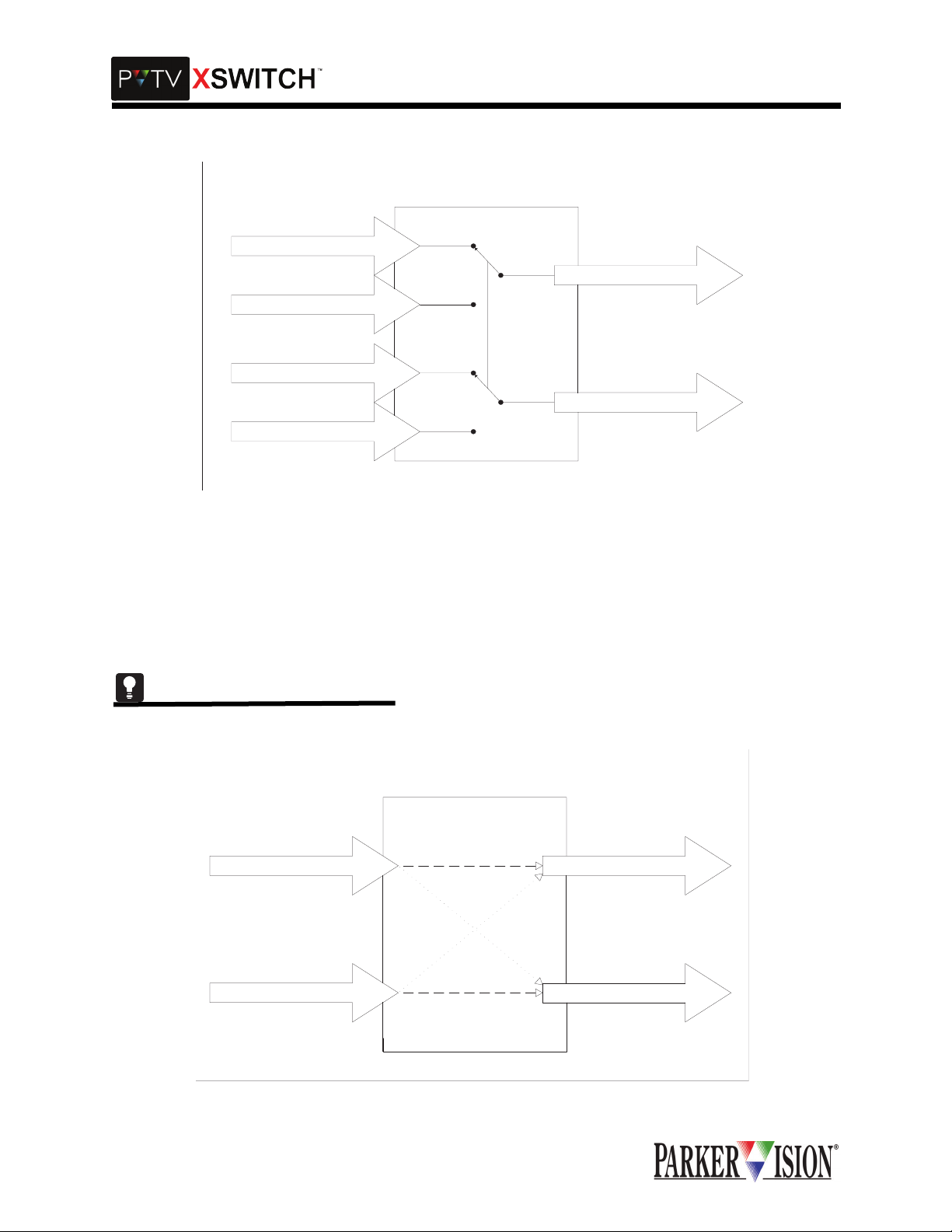
COMMUNICATION SIGNAL SWITCHING
The Comm Switch Card is a passive switching dev ice. There are no active electronics (semiconductor
devices such as ICs or discrete transistors) in the signal paths. The communication signal paths are
switched by relay contact. The I/O connectors on this card are 9-pin D type. Input (control source) connectors are female. Output (peripheral) connectors are male.
As a passive switch ing devi ce, the Comm S witch Card does not si gnific antly alte r or in any wa y affect th e
electrical character istic s of th e s ign al paths be ing switched. However, signal paths on the open s ide of th e
switch are not terminat ed. This car d empl oys a "for m C" conf igurati on and c an switch two sets of com munication ports. The typical topology would consist of one peripheral device and two control systems per set.
Both sets are switched simultaneously. Due to the passive switching ci rcuitry, the communication signals
can be of virtually a ny type such as RS232, RS422, RS48 5, etc. This card does not supp ort extremely
high-speed signal s wi tch in g s uc h as E the rn et. The ac tual c on tact e xcha nge oc c ur s within 6mS maximum ,
including settling tim e.
©2001 XSWITCH Installation and Operations Manual 1
Page 6
,QWURGXFWLRQ
PV Serial Data "Y"
Switch
PVTV A In
Source A
PVTV B In
PVTV A In
Source B
PVTV B In
SDI (VIDEO) SWITCHING
The SDI Switch Card is also a passive swit ching dev ice. Ag ain, relay contacts are used. The I/O connectors are standard BNC type. T his card is a cross switch. Two digital video signal sourc es are switched
between two receiving dev i ces. F o r ex amp le, an S DI s ig nal fr om di gital c am era A is fed to the s wi tch c ar d
and from there to digital mon itor A. A n SDI s ignal fr om di gital cam era B is fed to the swit ch card a nd f rom
there to digital monitor B. When the switch is thrown, camera A is connected to monitor B and camera B is
connected to moni tor A. No signal paths are left withou t termination except during the ac tual switching
event. The actual contact exchange, including settling time, consumes a maximum of 6mS.
Analog video can also be switched on this card.
PV Video "X"
Switch
Source A
Source B
2 ©2001 XSWITCH Installation and Operations Manual
Source A
Source B
Page 7
,QWURGXFWLRQ
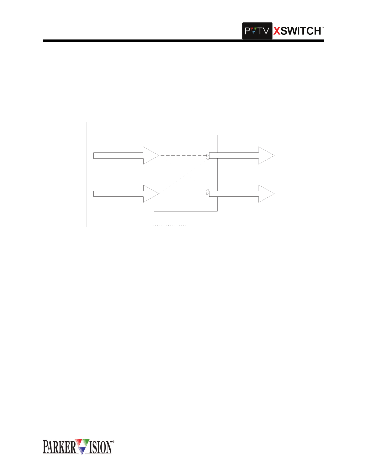
AUDIO SWITCHING
The Audio Switching C ar d is an a ctiv e sw itc hi ng de vi c e. It fu ll y bu ffers al l si gnal s and i s a "pop free" cross
switch. It uses active balanc ed inputs and outp uts. The I/O connec tor s ar e 3 pin XLR ty pe. The y are wi re d
with pin one at circuit ground, pin 2 hi and pin 3 lo. The input impedance is 2K Ohm. The output impedance
is 600 Ohm. In a typical application audio source A is input at input A and taken from output A to a receiving device. A second audio source is input at input B and taken from output B to a second receiving device.
When the switch is thrown, source A is connecte d to receiving device B and so urce B is connected to
receiving device A. The actual audio channel switching consumes a maximum of 50 mS.
PV Audio "X"
Switch
Source A
Source B
Normal Path
Switched Path
AUXILIARY VGA SWITCHING
Source A
Source B
Certain installations may require VGA switching capabili ty beyond that offered by the KVM Mod ule. An
auxiliary VGA switching card is available for such instances. This card is very similar to the Communication
Switch Card described ea rlier. Again, the signal pat hs are swi tched by passive rel ay co ntact. Signal paths
on the open side of the switch are not termin ated. It is a For m C type switc h with two inputs and one output. The connectors are high density 15 pin D type connectors for VGA interface (female inputs, male output). Contact exchange occurs within 6mS maximum, including settling time.
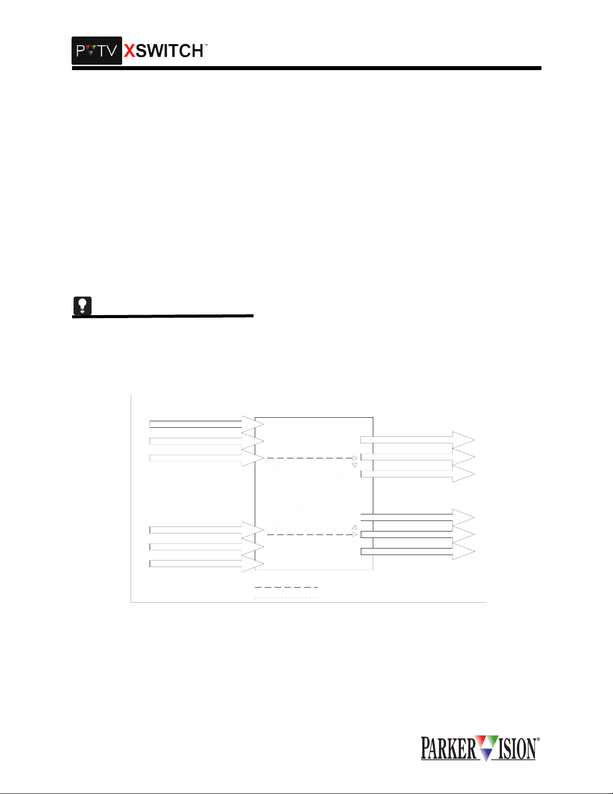
KVM SWITCHING
The KVM module contains bo th active and passive s witching. It is a dual c ross switch. It can h andle two
systems, each comprised of 2 keyboards, 2 mouse-type pointing devices and 4 VGA monitors. Each of the
two KVM systems can be switc hed independ ently of the other. The I/O connectors consist of high-density
15 pin D type connectors for VGA interface (female inputs, male outputs) and female MINI-DIN connectors
for keyboard and mouse interface.
In a typical application, the KVM module is used to switch VGA, keyboard and mouse connections
between two PVTV NEW S systems. I t can simultane ously and ind ependently sw itch two SCR IPT Viewer
systems, which emplo y the same co mponents. The switching func tions for the two PVTV NE WS systems
are independent of the switching functions for the two SCRIPT Viewer systems.
Looking at the KVM mo dule connec tor panel from the bac k of the rack, all PVTV NEWS connection s are
provided on the left-han d si de of the panel and a ll SCRIPT Viewer conne ct ion s ar e o n the rig ht- ha nd side .
On the STUDIO side, one VGA source (call it Left) is connected to "STUDIO A IN" in the "VGA LEFT" connector group. The second VGA sourc e from the same compu ter (R ight) is connected to "STUD IO A IN" in
the "VGA RIGHT" c onnector group. The (L) VGA monitor is conne cted to "STUDIO A O UT" in the VGA
LEFT connector group. T he ( R) VGA monito r is co nnecte d to "S TUDIO A O UT" in the "VGA RIG HT" c onnector group.
©2001 XSWITCH Installation and Operations Manual 3
Page 8
,QWURGXFWLRQ
The keyboard from the sa me PVTV NEWS sy stem is connec ted to the up per MIN I-DIN co nnecto r lab eled
"K" in the "STUDIO A" connec tor group. The mous e plugs into the upper MINI-DIN conn ector labele d "M"
in the "STUDIO A" connector group. Connections from the lower MINI-DIN connectors labeled "K" and "M"
are taken back to the keyboard and m ouse ports respecti vely of the associa ted computer.The same connections are repeated for the second PVTV NEWS system at the "STUDIO B" I/O connector group.
The SCRIPT Viewer systems are connect ed on the right-hand side of the conn ector panel, in the same
manner as the PVTV NEWS sy stems. Switchin g of the RGB portion of the V GA signal groups is handled
actively, while all other signals in this grou p are switch ed passively. This is done to maintain integrity and
cable drive capability of the RGB signals. Independent, active buffering and switching channels, which provide proper termination and standard 75 Ohm impedance characteristics, processes all video signals. Typical RGB video signal switching time is 5 nS. This is an insignificant time span relative to the switching time
of the VGA signal groups as a whole.
The keyboard and mouse switching is primarily passive, but does employ some semiconductor based
power coupling circuitry. Contact closure times do not exceed 6 mS for any portion of the KVM Module.
The XSWITCH can also b e expanded v er tica ll y by a ddi ng u p to 3 Ex pansion M odu les to a ny Master M odule. The Expansion Mo dule is 4 Rack Units and holds up to 10 switch cards. The indiv idual Expansion
Modules communi cate with each other throug h a SCSI connection. The Master Module still controls the
entire switching syst em, and com munic ates wit h the Expansion Mod ules through an RS232 connec tion. If
you need an Expansion Module, please contact ParkerVision Customer Support.
VGA In
PS2 In
PS2 In
VGA In
PS2 In
PS2 In
PV KVM "X"
Switch
VGA Out
PS2 Out
PS2 Out
VGA Out
PS2 Out
PS2 Out
Normal Path
Switched Path
4 ©2001 XSWITCH Installation and Operations Manual
Page 9
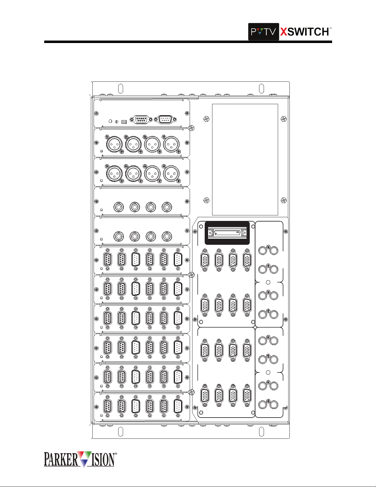
0DVWHU0RGXOH%DFNSODQH
,QWURGXFWLRQ
CPU
AUDIO
AUDIO
SDI
SDI
COMM
COMM
RESET
BOOT
A1
IN
A1
IN
A
IN
A
IN
BOOT
A
IN
A
IN
RUN
IN
B1
IN
B1
IN
B
IN
B
COMM
A
IN
B
IN
B
1
OUT
1
OUT
COMM
B
A
OUT
A
OUT
OUT
A
OUT
A
INB2IN
A2
INB2IN
A2
OUT
B
OUT
B
OUT
B
OUT
B
EXP
2
OUT
I
S
A
N
O
N
S.V. B
PROMPTER
2
OUT
IN
IN
S.V. A
OUT
S.V. A
S.V. B
IN
OUT
S.V. B
OUT
COMM
COMM
COMM
COMM
COMM
A1
IN
A1
IN
A1
IN
A1
A1
IN
IN
IN
B1
IN
B1
IN
B1
IN
IN
B1
B1
1
INB2IN
A2
OUT
1
INB2IN
A2
OUT
1
INB2IN
A2
OUT
1
1
INB2IN
INB2IN
A2
A2
OUT
OUT
2
OUT
EDITOR
2
OUT
VGA RIGHT
2
OUT
STUDIO AINSTUDIO A
2
2
OUT
OUT
VGA LEFT
OUT
STUDIO BINSTUDIO B
OUT
IN
S.V. A
STUDIO B
OUT
STUDIO A
KM KM KM MK
©2001 XSWITCH Installation and Operations Manual 5
Page 10
+DUGZDUH6HWXSDQG,QVWDOODWLRQ
8QSDFNLQJ
The following list indic ates the items tha t should have bee n shipped with the X SWITCH. If any items are
missing, contact ParkerVision immediately for the missing items.
HARDWARE
DSW-2000 XSWITCH Master Module (With installed Switch Cards)
DSW-2100 XSWITCH Expansion Module (With installed Switch Cards)
DOCUMENTATION
XSWITCH Installation and Operations Manual
0DVWHU0RGXOH6ZLWFK&DUG,QVWDOODWLRQ
The Master Module comes pr e-loaded with Switch Cards, however, it is important to note how cards are
installed in case a replac ement card or alte rnate card is ever nee ded. The informatio n below is for r eference in such cases.
CPU CARD INSTALLATION
The CPU card occupies the slot in the upper right hand co rner of the card cage, as viewed form the back .
Before the CPU card is installed, check to be sure the program/run switch is in the RUN position. To install
the CPU card, align the top and bot tom edges of the CIRCUIT BOARD (not the metal shee t to which the
board is mounted) with the nylon card guides inside the card cage. Slide the card all the way back until the
DIN connector on the card mates securely with the DIN connector on the backplane. The metal panel
should fit snugly aga inst the mountin g bars at t he back (th e side ne arest ins taller) of the card c age. Install
and tighten the two #4 machine screws to fasten the connector panel to the mounting bars.
There is only one slot in the Master Module for the CPU card.
GENERAL SWITCH CARD INSTALLATION
All other switch c ards are installed in the same manner as des cribed for the CPU c ard. Unlike the CPU
card, these cards can oc cupy any position in the upper half of the card cage. With the excep tion of the
Audio switch card, the re are no program ming jumpe rs or adjustm ents to be made on any of these switch
cards.
KVM MODULE INSTALLATION
The KVM Module connects to the backplane via a 34 conductor ribbon cable. The cable is terminated with
keyed 34 pin connector s. One end of the cable plugs into the backplane at J13 and the other end plugs
into the KVM module a t J11. The module then fastens to t he Master Mod ule chassis u sing 6 #4 mac hine
screws.
([SDQVLRQ0RGXOH6ZLWFK&DUG,QVWDOODWLRQ
The Expansion Module basically duplicates the upper half of the Master Module. It can hold up to 10 switch
cards in any order. Switch Cards are installed in exactly the same manor as in the Master Module. An eleventh slot, at the far right-hand end, holds the Expansion Card. It is installed in the same manor as the CPU
card in the Master Module. The Expansion Card p rovides c onnec tion poi nts for cab ling between the Ma ster Module and the Expansion Mod ule. It also provide s connection points for cabling between Expans ion
Modules. Up to 3 Expansion Modules can be ganged with one Master Module.
©2001 XSWITCH Installation and Operations Manual 7
Page 11
,QWHUFRQQHFWLRQVDQG6ZLWFKLQJ)XQFWLRQV
,QWHUFRQQHFWLQJ;6:,7&+DQG39791(:6
COMMUNICATION SWITCH CARD INTERCONNECTIONS
Each Communicati on Switch Card can switch 2 communic ation channels. E ach channel "outp ut" can be
switched between two "inputs.” In a typical ap plication, one communication port from PVTV STUDIO " A"
would connect to the first input of the first switching channel. One communication port from PVTV STUDIO
"B" would connect to the secon d inp ut of the first swi tc hi ng cha nne l. The output of the first switching channel connects to the comm unic ati on po rt of an y s eria l-c ontr ol la ble devi ce, su ch a s a VT R or c har acte r g enerator. The second switching cha nnel w ould c onnec t in the same m anor, to a second comm unica tion p ort
from each of the two PVTV NEW S system s and to the c ommuni catio n port of a se cond peri pheral de vice .
These connections a re al l mad e usi ng standard digital co mmunicati on c ables termina ted wit h 9 pin sub D
connectors. Inputs to the Communication Switch Card are female, outputs are male. These same directions should be fo llowed for utilizing each of the six Co mmunication Switch Cards in the Master Module.Refer to Table 1 and Figure 1 for more infomration.
The actual signal switc hing mechanism employed is passive and can therefore accommodate all ty pical
communication signaling methods, including RS232, RS485, RS422.
Verify that the communication sw itch card inputs are con nected to the same c ontrol ports of each PVT V
NEWS control module . For example, if the VTR is conne cted to control port 1 on ST UDIO A, the same
VTR should be connected to control port 1 on STUDIO B.
.
Table 1: Communication Interconnections
CONNECT TO
XSWITCH COMM
SWITCH CARD
CONNECT TO PVTV NEWS
A IN 1 Any Control Port (1-12) on
STUDIO A
B IN 1 Any Control Port (1-12) on
STUDIO B
OUT 1
A IN 2 Any Control Port (1-12) on
STUDIO A
B IN 2 Any Control Port (1-12) on
STUDIO B
OUT 2
CONNECT TO SERIALCONTROLLED DEVICE
Communication Port
Communication Port
©2001 XSWITCH Installation and Operations Manual 9
Page 12
,QWHUFRQQHFWLRQVDQG6ZLWFKLQJ)XQFWLRQV
Figure 1: Communication Switch Card Interconnections
COMM
COMM
IN
A1
IN
A1
IN
IN
B1
B1
OUT
OUT
1
1
IN
IN
A2
A2
COMM
COMM
COMM
COMM
COMM
B2
IN
B2
IN
A1
IN
A1
IN
IN
B1
B1
OUT
OUT
1
1
IN
IN
A2
A2
B2
IN
B2
IN
OUT
OUT
2
2
VGA LEFT
STUDIO A
STUDIO B
STUDIO A
OUT
STUDIO B
OUT
KM KM KM MK
OUT
STUDIO A
IN
IN
A1
IN
A1
IN
1
2
VGA RIGHT
STUDIO B
A1
IN
IN
B1
B1
OUT
OUT
1
1
IN
IN
A2
A2
2
2
OUT
OUT
B2
IN
B2
IN
OUT
OUT
2
2
EDITOR
S.V. A
IN
B1
OUT
IN
A2
B2
IN
OUT
IN
IN
IN
SDI
COMM
COMM
IN
A1
IN
A1
IN
IN
B1
B1
OUT
OUT
1
1
IN
IN
A2
A2
B2
IN
B2
IN
OUT
OUT
2
2
PROMPTER
S.V. A
IN
S.V. B
IN
S.V. A
OUT
S.V. B
OUT
IN
OUT
S.V. B
SDI
AUDIO
IN
INA
BIN
AOUT
BOUT
E
X
P
A
N
S
I
O
N
A
INA
BIN
B
IN
AOUT
OUT
A
BOUT
B
OUT
CPU
AUDIO
RESET
BOOT
IN
A
BOOT
RUN
B
IN
A
COMM
OUT
A
B
COMM
B
OUT
10 ©2001 XSWITCH Installation and Operations Manual
Page 13
,QWHUFRQQHFWLRQVDQG6ZLWFKLQJ)XQFWLRQV
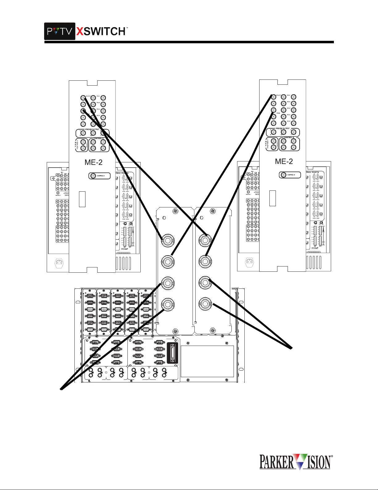
SDI/COMPOSITE VIDEO SWITCH CARD INTERCONNECTIONS
Each Video Swi tch Card can c ross- switch two v ide o outpu t sour ces be twe en tw o recei ving device s. Out put
from one video sou rce is connected to Switch Card input "A." The input to the receiving device is connected to Switch C ard output "A .” Output from a second video source is c onnected to Swi tch Card input
"B." The input to a second receiving dev ice is connected to Switch Card output "B." When the switch is
thrown, source "A" is connec ted to recei ving dev ice "B" while source "B" is connect ed to receiv ing devi ce
"A." This card can be used to s witch c omposite analog or SDI video s ignals. Ca ble connecti ons are mad e
using SDI compatible cabling terminated with 75 Ohm BNC connectors.
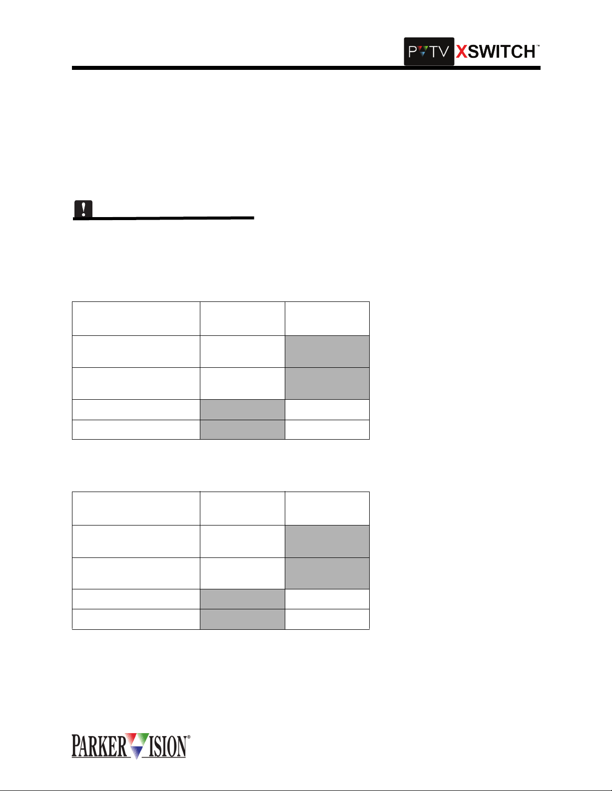
There are two SDI Sw itch Cards in the Master Module. One card con nects to Program output on PVT V
NEWS, and the other connects to Preview Out on PVTV NEWS. Refer to Tables 2 and 3 for more information.
Table 2: SDI Switch Card 1 Interconnections
CONNECT TO XSWITCH
SDI SWITCH CARD
CONNECT TO
PVTV NEWS
CONNECT TO
AIR
A IN STUDIO A ME-
2-OUT
B IN STUDIO B ME-
2-OUT
A OUT To Air
B OUT
To Air
Table 3: SDI Switch Card 2 Interconnections
CONNECT TO XSWITCH
SDI SWITCH CARD
CONNECT TO
PVTV NEWS
CONNECT TO
PREVIEW
A IN STUDIO A
PRVW Out
B IN STUDIO B
PRVW Out
A OUT Preview Monitor
B OUT Preview Monitor
©2001 XSWITCH Installation and Operations Manual 11
Page 14
,QWHUFRQQHFWLRQVDQG6ZLWFKLQJ)XQFWLRQV
Figure 2: SDI Switch Card Interconnections
COMM
COMM
COMM
COMM
COMM
COMM
IN
A1
IN
A1
IN
A1
IN
A1
IN
A1
IN
B1
B1
B1
B1
IN
IN
IN
1
1
1
OUT
OUT
OUT
A2
A2
A2
IN
IN
IN
B2
IN
B2
IN
B2
IN
2
2
2
OUT
OUT
OUT
VGA LEFT
KM KM KM MK
STUDIO A
STUDIO A
STUDIO B
STUDIO A
OUT
STUDIO B
OUT
OUT
IN
IN
IN
VGA RIGHT
STUDIO B
B1
IN
IN
1
1
OUT
OUT
OUT
A2
A2
IN
B2
IN
2
OUT
EDITOR
S.V. A
S.V. A
S.V. B
S.V. A
S.V. B
A2
B2
OUT
IN
IN
OUT
OUT
IN
OUT
IN
B2
IN
2
OUT
A1
B1
IN
IN
IN
1
2
PROMPTER
S.V. B
SDI
INA
BIN
AOUT
SDI
SDI
COMM
IN
A1
INA
B1
IN
BIN
BOUT
1
OUT
AOUT
A2
IN
B2
IN
BOUT
2
OUT
E
X
P
A
N
S
I
O
N
AUDIO
INA
BIN
AOUT
BOUT
SDI
INA
BIN
AOUT
IN
A
BOUT
IN
B
OUT
A
B
OUT
CPU
AUDIO
RESET
BOOT
IN
A
BOOT
RUN
IN
B
ACOMM
OUT
A
BCOMM
B
OUT
Preview
Monitor
AIR
12 ©2001 XSWITCH Installation and Operations Manual
Page 15
,QWHUFRQQHFWLRQVDQG6ZLWFKLQJ)XQFWLRQV
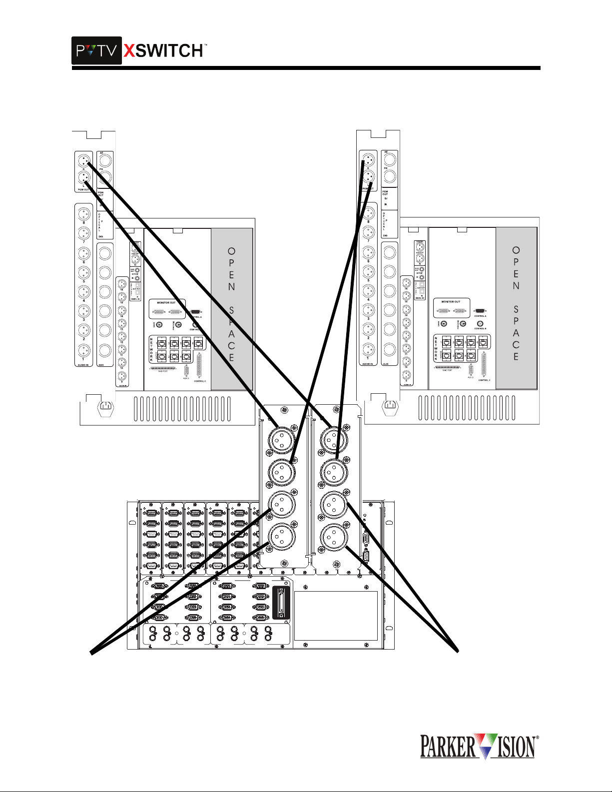
AUDIO SWITCH CARD INTERCONNECTIONS
Each Audio Swit ch Card can cross -switch two audio o utput sou rces betwee n two rec eiving dev ices. Bot h
switching channels employ active balanced inputs and outputs with unity gain throughput and flat frequency response acros s th e audi o spec tr um. In pra ctic e, the au dio outp ut fr om so urce "A " is con nec te d to
switch card inpu t "A." The input of a n audio receiv ing device is connected to swi tch card output "A." The
output from a secon d audio source is connected to swit ch card input "B." The input of a second audio
receiving device is connected to switch card output "B." When the switch is thrown, source "A" is connected to receivin g device "B" while source "B" is connected to receiving device "A." Conne ctions are
made using standard low impedance, balanced line, shielded cable terminated with three pin XLR connectors with pin-1 as groun d. Because the audio switchin g circuitry in this card employs a ctive electronics,
power must be on in order to pass audio signals through the XSWITCH.
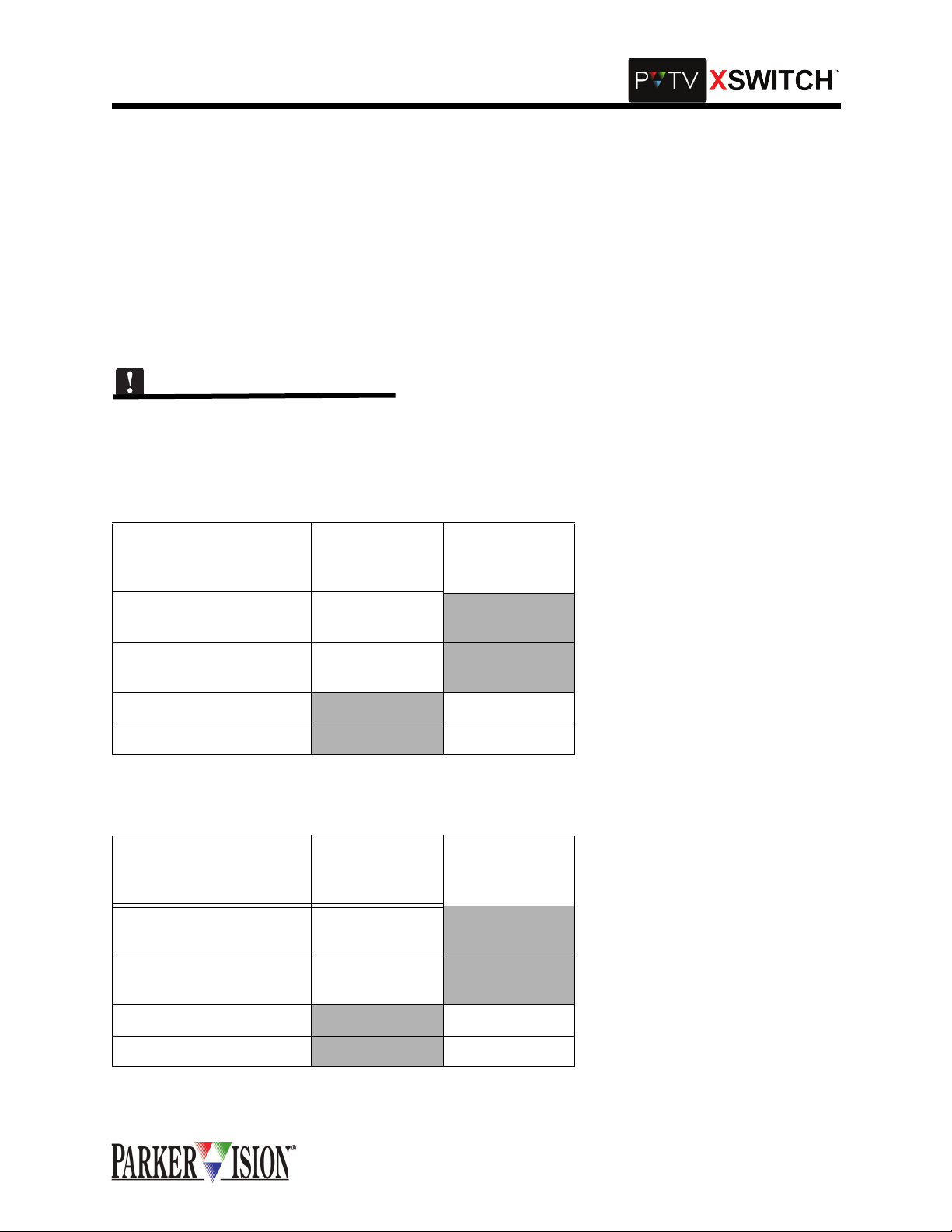
There are two Audio Switch Cards in the Master Module. One card connects to Program Output Left on the
PVTV NEWS Expanded A udio M odule, and th e ot her con nects to Pr ogram O utput Right o n PVTV NEWS
Expanded Audio Module. Refer to Tables 4 and 5 for more information.
Table 4: Audio Switch Card 1 Interconnections
CONNECT TO AUDIO
SWITCH CARD ON
XSWITCH
CONNECT TO
PVTV NEWS
OTHER
CONNECTION
A IN STUDIO A EAM
PGM OUT Left
B IN STUDIO B EAM
PGM OUT Left
A OUT TO AIR
B OUT
TO AIR
Table 5: Audio switch Card 2 Intreconnections
CONNECT TO AUDIO
SWITCH CARD ON
XSWITCH
CONNECT TO
PVTV NEWS
OTHER
CONNECTION
A IN STUDIO A EAM
PGM OUT Right
B IN STUDIO B EAM
PGM OUT Right
A OUT TO AIR
B OUT
TO AIR
©2001 XSWITCH Installation and Operations Manual 13
Page 16
,QWHUFRQQHFWLRQVDQG6ZLWFKLQJ)XQFWLRQV
Figure 3: Audio Switch Card Interconnections
TO AIR
COMM
COMM
COMM
COMM
COMM
COMM
IN
A1
IN
A1
IN
A1
IN
A1
IN
A1
B1
B1
B1
B1
IN
IN
IN
1
1
1
OUT
OUT
OUT
IN
IN
IN
A2
A2
A2
B2
IN
B2
IN
B2
IN
2
2
2
OUT
OUT
OUT
VGA LEFT
KM KM KM MK
STUDIO A
STUDIO A
STUDIO B
STUDIO A
OUT
STUDIO B
OUT
OUT
IN
IN
IN
VGA RIGHT
STUDIO B
B1
IN
IN
1
1
OUT
OUT
IN
IN
A2
A2
B2
IN
B2
IN
2
2
OUT
OUT
EDITOR
S.V. A
S.V. B
IN
S.V. A
OUT
S.V. B
OUT
IN
OUT
S.V. A
IN
A1
B1
OUT
A2
B2
OUT
IN
IN
1
IN
IN
2
PROMPTER
S.V. B
AUDIO
IN
A
B
IN
SDI
SDI
COMM
OUT
A
IN
A1
INA
B1
IN
1
OUT
IN
A2
B2
IN
2
OUT
E
X
P
A
N
S
I
O
N
INA
BIN
BIN
A
OUT
A
OUT
B
OUT
BOUT
BOUT
AUDIO
IN
A
IN
B
AUDIO
OUT
A
IN
A
IN
B
OUT
A
B
B
OUT
CPU
AUDIO
RESET
BOOT
IN
A
BOOT
RUN
IN
B
A
COMM
OUT
A
OUT
B
COMM
B
OUT
TO AIR
14 ©2001 XSWITCH Installation and Operations Manual
Page 17

,QWHUFRQQHFWLRQVDQG6ZLWFKLQJ)XQFWLRQV
AUDIO SWITCH CARD GROUNDING SWITCHES
There are three small slide swi tc hes on the Aud io Switc h ci rcu it boa rd, labe le d "S1 ", " S2" and "S 3." Th ese
switches allow various grounding schemes to be implemented and will ultimately be set according to
empirically established requirements of a particular installation. "S1" and "S2" provide a means of isolating
the shield ground at the X LR connection to the Audio Switch Car d. When these switches are open, th e
coaxial shield is NOT connected to circuit ground. This allows for connection of the shield at one end of the
cable only. When open, “S3” switches the cable connector housing of the outputs away from chassis
ground. The requirement for the setting of these 3 switches may vary from one system to the next and is to
be determined empirica lly. The card leaves the factory with all 3 switches in th e closed position. To open
any of the three switches, move the slider away from the connector panel.
KVM MODULE: VGA-SWITCH INTERCONNECTIONS
The KVM Module provides enough switching functionality to handle all VGA, keyboard and mouse connections from two PVTV NEWS s ystems and two PV TV SCRIPT Viewer syst ems. The s witchi ng circ uitry an d
connections for both PVTV NEWS systems occupy one half of the module while the other half is dedicated
to the two PVTV SCRIPT Viewer systems. Th ese two parts of the module can operate independ ently of
each other. The connector panel graphi cs extend th e divisio n into secti ons that grou p the conn ections for
each individual PVTV NEWS and each individual PVTV SCRIPT Viewer system.
The KVM Module can c ross-sw itch two se ts of VGA signa l groups. Typically, one set would consist of the
left and right monitors and dr iv in g sour c es fr om two P VTV NE WS sys tem s. T he o ther s et w oul d c ons ist o f
monitor and prompter VGA signals and driving sources from two PVTV SCRIPT Viewer systems. The
cable from VGA outpu t source_1 plugs into the connector labeled "ST UDIO A IN." The cable from VGA
output source_2 plugs into the co nnector lab eled "STUDIO B IN." The c able to VGA m onitor_1 plu gs into
the connector labeled "S TUDIO A OUT." The ca ble to VGA monitor_2 plugs into the connector labeled
"STUDIO B OUT." All four of these connectors are located at the left hand e nd of the conne ctor panel, in
the group labeled "VGA LEF T." All the VGA cabling from the second PVTV NE WS sy st em conn ec ts to the
KVM Module using the connectors in the group labeled "VGA RIGHT," in the same manor as described for
STUDIO A.
On the PVTV SCRIPT Viewer side of the module, the VGA cables connect to the KVM Module in the same
manor as described above for the PVTV NEWS side. VGA output sources connect to "S.V.A IN" and
"S.V.B IN" on the module. "S .V.A OUT" and "S.V.B OUT" on the m odule connect to the PVTV SCRIPT
Viewer monitor and VGA DA respectively . These four connections are made in the connector labeled "EDITOR" The second PVTV SCRIPT Viewer system c onne cts in the s ame man or at the four VGA connectors
in the group labeled "PROMPTER."
All VGA connections are made using standard VGA cable s terminated with 15 pin, high densi ty "D" connectors. KVM Module VGA inputs are male, outputs are female. The VGA switching circuitry is composed
of both passive and active elements. Therefore, power must be on in order to pass all VGA signals through
the XSWITCH.
©2001 XSWITCH Installation and Operations Manual 15
Page 18

KVM MODULE BACKPLANE
,QWHUFRQQHFWLRQVDQG6ZLWFKLQJ)XQFWLRQV
VGA LEFT
STUDIO A
STUDIO B
STUDIO A
STUDIO B
OUT
KM KM KM MK
OUT
STUDIO A
IN
IN
OUT
IN
VGA RIGHT
STUDIO B
EDITOR
S.V. A
IN
S.V. B
IN
S.V. A
OUT
S.V. B
OUT
IN
OUT
S.V. A
PROMPTER
E
X
P
A
N
S
I
O
N
S.V. B
16 ©2001 XSWITCH Installation and Operations Manual
Page 19

©2001 XSWITCH Installation and Operations Manual 17
Page 20

,QWHUFRQQHFWLRQVDQG6ZLWFKLQJ)XQFWLRQV
SWITCHED KEYBOARD AND MOUSE INTERCONNECTIONS
Each of the four connector groups, "STUDIO A" , " STUDIO B", "S.V.A", "S.V.B" includes switching connections for one mouse and one keyboard. These are the 5-pin circular DIN connectors along the bottom edge
of the panel. The keybo ar d I/O c onn ec tors ar e label ed " K" a nd the mouse I/O con nec tors a re labe led " M" .
The upper row of connector s are inputs and the lower row outputs. The ca ble from the STUDIO A keyboard plugs into t he co nnector in the upper row at the left end of th e panel, labele d "K". A cable from th e
associated CPU keyboa rd port plugs into the connector directly bel ow it. The cable from the S TUDIO A
mouse plugs into the connector immediately to the right and in the upper row, labeled "M". A cable from the
associated CPU mouse port plugs into the connector directly below it.
The keyboard and mouse associated with STUDIO B , connect to the KVM Module i n the same manor,
using the DIN connectors in the STUDIO B connector group.
The pattern is repeated for the keyboard an d mouse associated with PVTV SCR IPT Viewer A, using the
DIN connectors in the SCRIPT Viewer A connector group. And again for the keyboard and mouse of
SCRIPT Viewer B using the DIN connectors in the SCRIPT Viewer B connector group.
Keyboard and mous e switching events are strictly con current with associated VGA swi tching. The keyboard and mouse switc hing circuitry employs b oth passive and active elements. How ever, these circuits
may pass signals even while power is not applied to the XSwitch.
EXPANSION CARD INTERCONNECTIONS
A single cable is used to make the required connec tions between the main card cage and the Expansion
Card Cage. Connections between fi rst and se cond Ex pansion Card Cages and between s econd and thi rd
Expansion Card Cages are made using an identical cable. This cable is of a special type and must be provided by ParkerVision. The cabl e for the first Ex pansion Card Cag e plu gs in to the 50- p in hi gh den si ty connector at the right hand end of the KVM Module, labeled "EXPANSION". The other end plugs into the same
type connector locate d on the Expansion Card in the Expansion Card Cage lab eled "EXPANSION". If a
second Expansion Card Cage is employed, a second cable connects it to the first Expansion Card Cage at
either side of the dual 50-pin connector on the Expansion Card in the each Expansion Card Cage. If a third
Expansion Card Cage is employed, the pattern is repeated using a third cable connected between the second and third Expansion Card Cage.
18 ©2001 XSWITCH Installation and Operations Manual
Page 21

6RIWZDUH6HWXSDQG2SHUDWLRQ
2SHUDWLRQDO2YHUYLHZ
This overview presents a brief description of the XSWITCH’s operation, including a summary of the operational modes, as well as an ov erview of the main c ontro l panel, the status display and the spe cial func tion
keys.
SYSTEM ACCESS AND SETUP
Powering the XSWITC H on is done by turning on both power suppl y switches on the r ear panel. Both
switches will ill uminate when on. Following power-up, the XSWITCH wi ll initialize itself. Once i nitialized,
the system will display the Main Screen, which provides Switch Card Status information:
The icon in the bottom right corner indicates the current mode selection (A,B,C,D,or E).
To the left of this icon is the rack cage currently being displayed. In this case, Rack 0. The Master Module
is Rack 0. To switch to another rack, Use the Function Up and Function Down buttons.
Each slot in th e modu le is listed (1-10) . To the right of each card slot number is a shor t des criptio n of th e
card type in that slot. To the left of the card slot is a radio button i ndica ting the status of that car d (on/off).
If the radio button is hollow, the corresponding Swit ch Card is off. If the radio button is solid-fil led, the corresponding Switch Card is on.
To change from the Master Module to an Expansion Module, the mode select buttons on the front panel of
the XSWITCH may be used anytime.
©2001 XSWITCH Installation and Operations Manual 19
Page 22

6RIWZDUH6HWXSDQG2SHUDWLRQ
To switch to another rack, Use the Function Up and Function Down buttons.
XSWITCH MENU
The XSWITCH Menu is accessed by pressing the SEL button while the Main Screen is visible.
To select a menu item, press select while the desired menu item is highlighted on the XSWITCH Menu.
To choose a menu item, use the Function Up and Function Down Buttons.
Card Setup
The Card Setup Screen is displayed when selected from the XSWITCH Menu. This screen is used to configure Switch Card operation.
When the screen is firs t displayed, the Rack number will be flashing. Rack 0 correspon ds to the Master
Module. The Data Up and Data Down buttons are used to select the desired module (Rack number).
Press SEL To configure the indicated card rack.
A flashing cursor initial ly appears ov er Card 1, configu ration mode A. Pres s 'SEL' to toggle the s tate of
that card when that mode is selected . If a letter ap pears holl ow, that card will be OFF when tha t mode is
selected. (i.e. if 1-A is hollow, card 1 will be OFF when mode 'A' is selected). If a letter appears filled, that
card will be ON when that mode is selected (i.e. if 1-B is filled, card 1 will be ON when mode 'B' is
selected).
20 ©2001 XSWITCH Installation and Operations Manual
Page 23

6RIWZDUH6HWXSDQG2SHUDWLRQ
Use the Function Up and Function Do wn buttons to select a new card to configure , Use the Data Up an d
Data Down buttons to select a new mode configuration selection for that card.
Settings
The Settings Screen is displayed when selected from the XSWITCH Menu.
Master/Slave: If Master i s selected , the XSW ITCH mode will be determin ed by the A ,B,C,D,E button s on
the front panel. If Slave is selected, the XSWITCH mode will be determined by another Master device connected to the serial port on the CPU card. T he A,B,C,D ,E b uttons on the front panel wil l NOT chan ge the
mode while Slave is selected.
Screen Saver: Use the S EL bu tton to enab le/ dis ab le th e scr een saver. User the Data Up and Data Down
buttons to determine the length of inactivity before the screen saver becomes active.
Use the Function Up and Function Down buttons to select a setting.
Use the Data Up, Data Down, and SEL buttons to change the selected setting.
Diagnostics
The Diagnostics Screen is displayed when selected from the XSWITCH Menu.
A square is displayed representing each button on the front panel.
Pressing a button on the front panel will Fill-in the corresponding button representation on the LCD,
verifying the operation of the button pressed.
©2001 XSWITCH Installation and Operations Manual 21
Page 24

6RIWZDUH6HWXSDQG2SHUDWLRQ
About
The About Screen is displayed when selected from the XSWITCH Menu.
The about screen displays the product name, version, copyright message, Company information, PQ
revision number, and compile date for the software.
Restoring Factory Default Settings
To restore factory default settings - press and hold Function Up and Function Down for three seconds.
The following screen will be displayed.
This will overwrite all user settings.
XSWITCH will default to configuration mode A.
All card settings will default to ON for configuration mode B, and OFF for all other modes.
Master/Slave setting will default to Master.
Screen saver will default to OFF, and 30 minutes.
SAMPLE STEP-BY-STEP PROCEDURE
The following steps demonstrate how to configure a SWITCH CARD. Assuming there is an SDI card in slot
three, this example will co nfi gur e it t o be on and al l othe r ca rds o ff wh en m ode 'C' i s selected. These procedures assume the XSWITCH is curren tly configured to fac tory defaults, is powere d on, and displayin g
the Main Screen.
1. Power on the XSWITCH.
2. The 'Main Page' should be displayed.
3. Press the 'SEL' button.
4. This will bring up the 'Menu Page'.
22 ©2001 XSWITCH Installation and Operations Manual
Page 25

6RIWZDUH6HWXSDQG2SHUDWLRQ
5. Ensure the 'Card Setup' Option is highlighted using the 'Function Up' and 'Function Down'
buttons.
6. Press the 'SEL' button.
7. The current rack being displayed should be flashing in the bottom right corner.
8. Ensure Rack 0 is selected using the 'Data Up' and 'Data Down' buttons.
9. Press the 'SEL' button.
10. The 'A' icon for Slot 1 should now be flashing.
11. Press the 'Function Down' but ton twice to move the flashing cursor to the Slot 3 mode array
icons.
12. Press the 'Data Down' button twice to move the flashing cursor to the 'C' icon.
13. Press the 'SEL' button to change this icon from a hollow fill t o a soli d fill.
14. The solid fill for Slot 3 icon array 'C' indicates this card will be on when mode 'C' is selected.
15. ‘C' icons for all other cards should already be hollow indicating they are off when mode 'C' is
selected.
16. Press 'ESC' twice to return to the 'Main Page'.
RESULTS: Pressing the Mode 'C' button will now cause the SDI card in slot 3 to be on while all other cards
are off.
Card State - 'Off' is used to mean th e card is in its no rmal or unswitched s tate (inputs marked A will be
routed to outputs marked A, inputs marked B, if available, will be routed to outputs marked B). 'On' is used
to describe a card in its active or switched state (inputs marked A will be routed to outputs marked B, inputs
marked B, if available, will be routed to outputs marked A).
©2001 XSWITCH Installation and Operations Manual 23
Page 26

$SSHQGL[$5HPRWH$FWLYDWLRQ
The PVTV XSWITCH has remote activation capabilities. The following information is a communication
guide to assist with use of this functio nality. Connector and pinout informati on is also suppl ied. ParkerVision does not offer a remote activation device. This device must be supplied by the customer.
A standard bus communication consis ts o f a command sent b y an originating de vice to a receiv ing d evi c e
with the receiving device returning a reply. If the reply is not received within a designated time period, then
the originating device has the option to retry or cancel the command.
Hardware Specifications
The computer may listen, talk, or interrupt bus comms at any time. The active lines to the RS-232 port are
TXD, RXD, and ground, as shown in the Installation Manual. No hardware handshaking is used. The RS232 port signal levels are +12 and -12 volts.
Care must be taken to insure that the electrical connections are of the correct polarity and voltage, or damage may result. Be sure to consult the particular device connector diagrams for correct signal pinouts and
polarities.
Bus Packet Format
ParkerVision communic ation packets co nsist of 10-bi t words c ontaining 1 start bit, 8 data bits, an d 1 sto p
bit. The words are transmitted one bit at a time (serially), least-significant bit first. The data rate is fixed at
9600 baud. Successive wo rds in a packet m ust follow o ne another within 20 mi llisecond s or the packet is
declared invali d. There must be a minimum delay of 4 0 milliseconds betw een successive packets. A ny
computer connected to the communication bus must adhere to these packet specifications. The bus
comms are half-duplex.
Command and reply packets are organi zed similarly, the only difference being that reply packets do not
have a Command/Control field. Packets are ordered as follows:
0 1 2 LEN+3 LEN+4 LEN+5
DEST SRC LEN C/C DATA1 … DATAn CRCL CRCH
Note: When using the Basic Protocol, the two CRC bytes are not used.
• DEST: Destination Address field (1 word). Range: 0-255 binary. This is the address of the device to
which packet is being sent. Address 255 is a Broadcast address. Broadcast packets are received by
all devices, but no reply is sent. (Default Address 0)
• SRC: Source Address field (1 word). Range: 0-254 binary. This is the address of the device from
which the packet is being sent. (Default Address 255)
• LEN: Length of data field (1 word). Range: 1-256 (0=255) binary. The packet data field includes
words following the length word up to, but not including, the CRC field.
• C/C: Command/Control field (1 or more words). Command codes are ASCII numbers ranging from 0
to 255. Control codes are binary numbers ranging from 0 to 47.
• DATAn: Data field (0 or more words). The data field can be empty, or contain either ASCII or binary
words. If the data is ASCII, then, in the case of a command packet, data is separated by a comma (,),
and in the case of a reply packet, data is separated by a colon (:). Binary data has no explicit separator.
(see particular device command list for further information).
• CRCL: Lower half of cyclic redundancy check (1 word). The CRC computes using the CRC-CCITT
polynomial: x^16 + x^12 + x^5 + 1
• CRCH: Higher half of cyclic redundancy check (1 word)
Error recovery is handled by the originating device. This device may choose to terminate or re-transmit the
command.
©2001 XSWITCH Installation and Operations Manual 25
Page 27

$SSHQGL[$5HPRWH$FWLYDWLRQ
Note: All bus communications are half-duplex.
Universal Command/Control Codes
UNIVERSAL COMMAND CODES (ALL VALUES IN ASCII):
0....................... Send device ID and firmware version number.
Example reply:
15:1.0 (ID code = 15, firmware version = 1.0)
0,1.................... Send copyright message.
Example reply:
XSWITCH™ Ver 1.0 Copyright 2001, ParkerVision
26 ©2001 XSWITCH Installation and Operations Manual
Page 28

Communication Flow Chart
Send Command
Packet
Initialize UART
1 Start Bit
8 Data Bits
1 Stop Bit
CRC <- 0
Count <- Len + 3
Update CRC
Send Byte
Count <- Count - 1
$SSHQGL[$5HPRWH$FWLYDWLRQ
Count = 0?
YES
Send CRC
Done
NO
©2001 XSWITCH Installation and Operations Manual 27
Page 29

$SSHQGL[$5HPRWH$FWLYDWLRQ
Receive Reply Packet
Initialize Uart
1 Start Bit
8 Data Bits
1 Stop Bit
CRC <- 0
Count <- 3
Load Time-Out
(user defined)
Input Byte? Time-Out?
Yes
Update CRC
Count<-Count - 1
Load Time-Out
(30 mSec)
No
Count = 0?
No
Yes
Error
No
Yes
No
A
Count<- Len +2
Load Time-Out
(30 mSec)
Input Byte?Time-Out?
Yes
Update CRC
Count<-Count - 1
Load Time-Out
Count = 0?
Yes
Done
Yes
Count = 0?
No
Error
Yes
A
28 ©2001 XSWITCH Installation and Operations Manual
Page 30

Update CRC
Count <- 8
B <- CRC.0 XOR Byte.0
CRC <- CRC Shifted
Right 1
B = 1?
Yes
CRC <- CRC XOR 8408H
$SSHQGL[$5HPRWH$FWLYDWLRQ
NO
Byte <- By te Shifted R i ght 1
Count <-C ount - 1
NO
Count = 0?
Yes
Done
©2001 XSWITCH Installation and Operations Manual 29
Page 31

$SSHQGL[$5HPRWH$FWLYDWLRQ
Commands
Device ID: The following command is used to obtain the device ID type.
Command: 0 - Get Device ID Code
_____________________________________________________________________________________
Parameters Reply
None..........................(Send copyright message) Copyright Message
_____________________________________________________________________________________
Definitions:
_____________________________________________________________________________________
Examples: Reply
0,1 XSWITCH Ver 1.0 Copyright 2001, ParkerVision
Get/Set Switch State: The following command is used to get or set the switch state
Command: 1 - Get/Set Switch State
_____________________________________________________________________________________
Parameters Reply
None..........................(Send Switch State) [ A - E ]
[ A - E ].......................(Set Switch State) [ A - E ]
_____________________________________________________________________________________
Definitions:
[ A - E ] - ASCII characters 'A' through 'E'
_____________________________________________________________________________________
Examples: Reply
Get current switch state
1A
Set switch state to 'B'
1,B B
Set switch state to 'C'
1,C C
Screen Capture: The following command is used to capture data currently displayed on the LCD.
Command: 2 - Screen Capture
_____________________________________________________________________________________
30 ©2001 XSWITCH Installation and Operations Manual
Page 32

Parameters Reply
None..........................(Send Screen Data) [ Screen Data ]
_____________________________________________________________________________________
©2001 XSWITCH Installation and Operations Manual 31
Page 33

$SSHQGL[$5HPRWH$FWLYDWLRQ
Definitions:
Screen Data - The screen data is too large for the normal parkervision protocol. It is sent without any protocol wrapping. Immediately after sending this command the following packet will be returned...
[ Width ] [ Height ] [ Bitmap Data ]
Width = The LCD width in pixels ( 120 )
Height = The LCD height in pixels ( 80 )
Bitmap Data = Monochrome bitmap data of ( Width * Height ) / 8 in length. (1200 bytes)
_____________________________________________________________________________________
Examples: Reply
Get Screen Capture
2 [ 120 ] [ 80 ] [ .....1200 Bytes ..... ]
* The XSWITCH will pause briefly while sending the data.
** This command should not be used during normal operations.
32 ©2001 XSWITCH Installation and Operations Manual
Page 34

$SSHQGL[$5HPRWH$FWLYDWLRQ
Calculating the CRC
Given: The XSWITCH information for the fields:
DEST SRC LEN C/C DATA1 … DATAn CRCL CRCH
and the basic program to calculate the CRC:
BASIC CRC PROGRAM VER. 2.0 USING VISUAL BASIC 3.0
Static P(200) As Integer
ICRC = 0
POLY = &H8408
Dstring$ = Input_Text$ ‘ This is the input string.
D = 0
i = 1
P(0) = 0
For J = 1 To Len(Dstring$)
c$ = Mid$(Dstring$, J, 1)
Casc = Asc(c$) ‘ Finds decimal value contained in character’s ASCII value.
D = D * 16 + Casc ‘ Hex value calculated.
P(0) = P(0) + 1
P(i) = D
i = i + 1
D = 0
Next J
‘ After calculating input string’s characters to hex value,
CRC = ICRC Calculate the CRC.
For i = 1 To P(0)
D = P(i)
For J = 1 To 8
XFLG = (CRC Xor D) And 1
CRC = Int(CRC / 2) And &H7FFF
If XFLG Then CRC = CRC Xor POLY
D = Int(D / 2)
Next J
Next i
....................... CrCHexValue$ = Hex$(CRC) ‘ This is ENTIRE CRC string.
dummylength = Len(CrCHexValue$)
LSB = Val(“&H” + Right$(CrCHexValue$, 2)) ‘ Convert hex value to decimal value.
MSB = 0
If dummylength = 3 Then MSB = Val(“&H” + Left$(CrCHexValue$, 1))
If dummylength > 3 Then MSB = Val(“&H” + Mid$(CrCHexValue$, dummylength - 3, 2))
Packet$ = Dstring$ + Chr$(LSB) + Chr$(MSB) ‘ This is the packet string.
End
Where the input string is made up of single characters to represent the field’s decimal value in the character’s own
ASCII value AND the actual command string for the XSWITCH.
©2001 XSWITCH Installation and Operations Manual 33
Page 35

$SSHQGL[$5HPRWH$FWLYDWLRQ
EXAMPLE 'C' PROGRAM
//==================================================================
// UpdateCRC16()
//==================================================================
Calculated: X^16 + X^12 + X^5 + 1
//
//-----------------------------------------------------------------UINT UpdateCRC16( BYTE b, UINT crc )
{
unsigned int i;
// Calculate CRC
for( i = 0; i < 8; i++ )
{
if ( ( crc ^ b ) & 1 ) crc >>= 1, crc ^= 0x8408;
else crc>>=1;
b >>= 1;
}
return crc;
} // end UpdateCRC16()
//==================================================================
// CalcCRC16()
//==================================================================
UINT CalcCRC16( LPBYTE buf, DWORD size )
{
UINT crc = 0;
// Calc CRC16 on buffer
for ( DWORD i = 0; i < size; i++ )
crc = UpdateCRC16( buf[ i ], crc );
} // end CalcCRC16()
34 ©2001 XSWITCH Installation and Operations Manual
Page 36

$SSHQGL[$5HPRWH$FWLYDWLRQ
EXAMPLE FOR BASIC PROGRAM V 2.0:
Known command string to send: “2,L”
LEN is length of command string.
Known values:
DEST: 04 decimal value —> convert to ASCII character of value: 04
SRC: 254 decimal value —> convert to ASCII character of value: 254
LEN: 03 decimal value —> convert to ASCII character of value: 03
Input string for CRC program: Chr$(4)+Chr$(254)+Chr$(3)+”2,L”
Returned hexadecimal CRC value returned from basic program under Visual Basic: “FFFFFA92”
LSB needed from CRC is 92
MSB needed from CRC is FA
Using the standard protocol:
DEST SRC LEN C/C DATA1 … DATAn CRCL CRCH
Where the CRCL is the LSB needed from CRC and the CRCH is the MSB needed from CRC,
the entire packet is now in the form (using values from previous example):
packet string = Chr$(4)+Chr$(254)+Chr$(3)+”2,L”+Chr$(&H92)+Chr$(&HFA)
NOTES: LSB and MSB of CRC are hexadecimal values. Remember to change back to decimal
form to use Chr$ or use hexadecimal notation.
Basic eliminates leading zeros. Therefore if CRC returns only 3 characters, the last two are LSB
and the first character from CRC is MSB.
i.e.: CRC=“3FE”, LSB=FE MSB=3
i.e.: CRC=“2E”, LSB=2E MSB=0
©2001 XSWITCH Installation and Operations Manual 35
Page 37

$SSHQGL[$5HPRWH$FWLYDWLRQ
OTHER EXAMPLES:
Known: For all rest of examples, DEST=4, SRC=254.
1. command string = “4”
LEN = 1
input string for CRC = Chr$(4)+Chr$(254)+Chr$(LEN)+command string
CRC program returns:
complete CRC string = “FFFF80BC”
LSB needed from CRC = “BC”
MSB needed from CRC = “80”
packet string = Chr$(4)+Chr$(254)+Chr$(LEN)+command string
+Chr$(&HLSB)+Chr$(&HMSB)
2. command string = “1,P,255,0, 0”
LEN = 11
input string for CRC = Chr$(4)+Chr$(254)+Chr$(LEN)+command string
CRC program returns:
complete CRC string = “FFFFC67F”
LSB needed from CRC = “7F”
MSB needed from CRC = “C6”
packet string = Chr$(4)+Chr$(254)+Chr$(LEN)+command string
+Chr$(&HLSB)+Chr$(&HMSB)
3. command string = “2,S”
LEN = 3
input string for CRC = Chr$(4)+Chr$(254)+Chr$(LEN)+command string
CRC program returns:
complete CRC string = “12E4”
LSB needed from CRC = “E4”
MSB needed from CRC = “12”
packet string = Chr$(4)+Chr$(254)+Chr$(LEN)+command string
+Chr$(&HLSB)+Chr$(&HMSB)
4. command string = “2,R,61,20”
LEN = 9
input string for CRC = Chr$(4)+Chr$(254)+Chr$(LEN)+command string
CRC program returns:
complete CRC string = “FFFF8758”
LSB needed from CRC = “58”
MSB needed from CRC = “87”
packet string= Chr$(4)+Chr$(254)+Chr$(LEN)+command string +Chr$(&HLSB)+Chr$(&HMSB)
5. command string = “2,3,131,20”
LEN = 10
36 ©2001 XSWITCH Installation and Operations Manual
Page 38

input string for CRC = Chr$(4)+Chr$(254)+Chr$(LEN)+command string
CRC program returns:
complete CRC string = “FFFFA78D”
LSB needed from CRC = “8D”
©2001 XSWITCH Installation and Operations Manual 37
Page 39

$SSHQGL[$5HPRWH$FWLYDWLRQ
MSB needed from CRC= “78”
packet string = Chr$(4)+Chr$(254)+Chr$(LEN)+command string
+Chr$(&HLSB)+Chr$(&HMSB)
6.command string = “1,P,0,0,0”
LEN = 9
input string for CRC = Chr$(4)+Chr$(254)+Chr$(LEN)+command string
CRC program returns:
complete CRC string = “3AE5”
LSB needed from CRC = “E5”
MSB needed from CRC = “3A”
packet string= Chr$(4)+Chr$(254)+Chr$(LEN)+command string +Chr$(&HLSB)+Chr$(&HMSB)
Connector and Pinout Specifications
The connector type is a standard DB9. There is one male (J3) and one female (J4) connector. The controlling device (PC) would typically connect to J4.
These are standard, 3 wire RS-232 connections that allow communications between a controlling device
(such as a PC) and the XSWITCH.
They also facilitate communication between multiple XSWITCH units. Pinout information is as follows:
PIN#
J3
1NC
2TX
3RX
4NC
5GND
6NC
7NC
8NC
9NC
J4
1NC
2TX
3RX
4NC
5GND
6NC
7NC
8NC
9 NC
NAME
38 ©2001 XSWITCH Installation and Operations Manual
Page 40

$SSHQGL[%&DQG'3RVLWLRQ([DPSOH
The PVTV XSWITCH pro vide d wi th d ual PV T V NEWS sy s tems a nd s ol d a s a stand al one uni t i s inte nde d
as an A to B mode of operation. This mean s tha t the ar ch itec tur al intent is su ch that any pr oblem with the
natural on-line sy stem, "A,” has a one-s witch ope ration to run from the backup s ystem, " B.” Furthermo re,
the intent is for operators to control both systems from a single control surface reg ardless of the on-line
system. Architectural intent is for the off-line system to be operationally active on a second control surface
for pre-production w ork in normal operatio ns or used for troubles hooting a system with problems off-line.
Due to the architectura l intent of the XSW ITCH it is sold with a minimu m number of card s to design with
your system. Beca use so me custom ers ha ve spe cial n eeds for their sy stem, th e XSWI TCH has a total of
5 "switched" selecti ons an operator can choose from for different operatio nal functions. The individual
switch cards can be pur chas ed separately for cu stom des igns. Apart from th e main fr ame whic h contains
the control panel, up to 3 expansion frames can be stacked, programmed and controlled by the main
frame.
The following is an example of dual PVTV NEWS system with a PVTV XSWITCH integration that utilizes
the A, B, C and D positions.
Overview
A and B position functiona lity rem ains cons tant in this applic ation but adde d redundan cy and functio nality
were desired. C position was created to control the A system from the pre-production control surface.
Consideration for the C po si tio n was to co mpe ns ate fo r the los s of a d ev ice on the on- l ine co ntrol su rf ace ,
i.e., computer monitor. In the event of such a failure, the operator is able to depress the C button and all
operations are switc hed to t he off-line c ontrol s urface with no chang e in op erati onal status. At the time o f
the switch, the on-l ine control sur face can be repair ed, (monitor s wap out), without interfering with on-air
operations. D positio n was create d to contro l the A sys tem from the on-line contro l surface and the B sy stem from the off-line c ontrol surface with the exception that the B sy stem and off-line control surface are
switched to air. Consideration for the D p osi tion was to allow a show being pr e- produ ce d to be br oug ht t o
air without the file transfers and ph ysical rel ocation of the oper ators to occ ur, (the pre-production ran long
and there was no time to run the show from the normal on-line control surface and A system). Once again
this is a one button push action to initiate.
Architecture
To support the C and D positions outlined above, there is the necessity of both added hardware and rewiring of certain shared devic es. The changes are outlined below an d are classified by the shared device
which needs to be controlled.
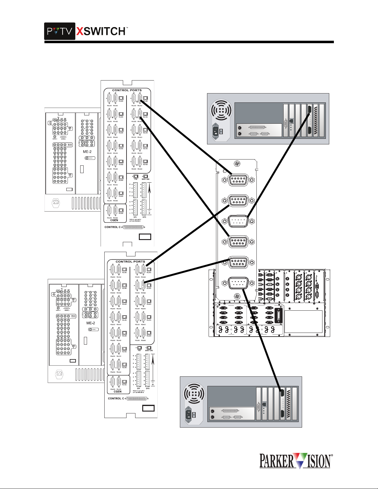
PVTV SHOT Director
In a normal A/B sw itch environment a singl e SHOT Director is used and integrated with a dual system.
This SHOT Director is used at t he on-line c ontrol surf ace. A second SHOT Dire ctor is pro vided with dual
systems but the intent of the seco nd uni t is as a r eady spare. To fully utilize the ca pability of the C and D
positions outlined abo ve , the s ec ond SHOT Di rec tor wi ll be located at the off-line control surface and bot h
units will be wired as illustrated in figure A-1.
©2001 XSWITCH Installation and Operations Manual 39
Page 41

$SSHQGL[%&DQG'3RVLWLRQ([DPSOH
A
System
Control Port
RS-232
B
Dual
Serial
Card 1
A In
C Out
B In
A In
Com 2
On-Line
Control
Surface
RS-485
Dual
Serial
Card 2
A In
C Out
B In
A In
To Cameras
System
Com 2
Off-Line
Control
Surface
Fig A-1
RS-485
Control Port
RS-232
C Out
B In
PVTV SHOT DIRECTOR (CONT.)
Operationally in the A pos ition , the camer as ar e contr olled by the On-Li ne Contro l Surfac e SHOT Director
which is being controlled by the A system. Dual Serial Card 1 and Dual Serial Card 2 are in the A position.
(See figure A-2)
Dual
A
System
Serial
Card
C Out
B In
Dual
Serial
Card
Control Port
A In
B In
C Out
Com 2
On-Line
Control
Surface
RS-485
A In
B In
C Out
To Cameras
B
A In
A In
System
Com 2
Off-Line
Control
Surface
RS-485
Control Port
C Out
B In
With the XSWITCH Main Frame in the B position, Dual Serial Card 1 will switch. This will connect the OnLine Control Surface SHO T Director to the B system. Dual Ser ial Card 2 will re main unswitched and will
continue to allow control of the cameras by the On-Line Control Surface SHOTt Director. See figure A-3.
C Out
B In
Figure A-2
40 ©2001 XSWITCH Installation and Operations Manual
Page 42

$SSHQGL[%&DQG'3RVLWLRQ([DPSOH
A
System
Control Port
Dual
Serial
Card
A In
C Out
B In
Com 2
On-Line
Control
Surface
RS-485
Dual
Serial
Card
A In
C Out
B In
To Cameras
B
A In
A In
System
Com 2
C Out
Control Port
B In
With the XSWITCH Main Frame in the C position, Dual Serial Card 2 will switch connecting the cameras to
the Off-Line Control Surface SH OT Di recto r. Dual Serial Card 1 will sw itch wh ic h wil l conn ec t the O ff-Line
Control Surface SHOT Di rector to the A system. Dual S erial Card 2 will switch will conn ect the Off-Line
Control Surface Shot Director to the cameras. See figure A-4.
Off-Line
Control
Surface
RS-485
C Out
B In
Figure A-3
Dual
Serial
Card
C Out
B In
To Cameras
A
System
Control Port
Dual
Serial
Card
A In A In
Com 2
C Out
B In
On-Line
Control
Surface
RS-485
B
A In
A In
System
Com 2
RS-485
Off-Line
Control Port
B In
Control
Surface
With the XSWITCH Main Frame in t he D positi on, Dual Seri al Card 2 wil l switch , connecting the camer as
to the Off-Line Control Surface SHOT Director. Dual Serial Card 1 will switch connecting the Off-Line Control Surface SHOT Director to the B system. See figure A-5.
C OutC Out
B In
Figure A-4
©2001 XSWITCH Installation and Operations Manual 41
Page 43

$SSHQGL[%&DQG'3RVLWLRQ([DPSOH
Dual
Serial
Card
A In
C Out
B In
To Cameras
A
System
Control Port
Dual
Serial
Card
A In
C Out
B In
Com 2
On-Line
Control
Surface
RS-485
B
A In
A In
System
Com 2
Off-Line
Control
Surface
RS-485
Control Port
ARCHITECTURE (CONT.)
C Out
B In
Prompter Controller (SSC-2000)
In a normal A/B sw itch environm ent, a single Pr ompter Control ler is used and integrate d with a dual sy stem. This Prompter Controller is used at the on-line control surface. A second Prompter Controller is provided with dual systems but the intent of the second unit is as a ready spare. To fully utilize the capability
C Out
B In
Figure A-5
42 ©2001 XSWITCH Installation and Operations Manual
Page 44

$SSHQGL[%&DQG'3RVLWLRQ([DPSOH
6
of the C and D positions outlined o n page 1 of A ppen di x B , the s econd Pr omp ter Con t roll er wil l be locate d
at the off-line control surface and both units will be wired as illustrated in figure A-6.
Dual
A
System
Control Port
B
System
Control Port
Serial
Card
A In
C Out
B In
A In
C Out
B In
On-Line
Control
Surface
Off-Line
Control
Surface
Figure A-
©2001 XSWITCH Installation and Operations Manual 43
Page 45

$SSHQGL[%&DQG'3RVLWLRQ([DPSOH
7
Prompter Controller SSC-2000 (cont.)
Operationally in the A positi on, the promptin g is controlled by the On -Line Cont rol Surface Prompter Controller which is conected to the A system. The Dual Serial Card is in the A position. See figure A-7.
Dual
A
System
Control Port
B
System
Control Port
Serial
Card
A In
C Out
B In
A In
C Out
B In
On-Line
Control
Surface
Off-Line
Control
Surface
Figure A-
44 ©2001 XSWITCH Installation and Operations Manual
Page 46

$SSHQGL[%&DQG'3RVLWLRQ([DPSOH
8
With the XSWITCH Mai n Frame in the B pos ition, the Dual Serial Card will s witch. This wil l connect the
On-Line Control Surface Prompter Controller to the B system. See figure A-8.
Dual
A
System
Control Port
B
System
Control Port
Serial
Card
A In
C Out
B In
A In
C Out
B In
On-Line
Control
Surface
Off-Line
Control
Surface
Figure A-
©2001 XSWITCH Installation and Operations Manual 45
Page 47

$SSHQGL[%&DQG'3RVLWLRQ([DPSOH
9
With the XSWITCH Main Frame in the C position , the Dual Serial Card will sw itch which will conne ct the
Off-Line Control Surface Prompter Controller to the A system. See figure A-9.
Dual
A
System
Control Port
B
System
Control Port
Serial
Card
A In
C Out
B In
A In
C Out
B In
On-Line
Control
Surface
Off-Line
Control
Surface
Figure A-
46 ©2001 XSWITCH Installation and Operations Manual
Page 48

$SSHQGL[%&DQG'3RVLWLRQ([DPSOH
0
With the XSWITCH Main Frame in the D position, the Dual Serial Card will switch, connecting the Off-Line
Control Surface Prompter Controller to the B system. See figure A-10.
Dual
A
System
ScriptViewer
Com Port
Serial
Card
A In
C Out
B In
On-Line
Control
Surface
B
A In
System
C Out
ScriptViewer
Com Port
B In
PVTV Camera Prompter Monitors
In a traditional A/B switch application, the PVTV Camera Prompter Monitors are fed from the KVM Module.
To utilize the C and D modes as outli ned in this appendix , a 15pinHD Y Switch will hav e to be purcha sed
from ParkerVision and installed in one of the open slots in either the XSWITCH Main Frame or an
Off-Line
Control
Surface
Figure A-1
©2001 XSWITCH Installation and Operations Manual 47
Page 49

$SSHQGL[%&DQG'3RVLWLRQ([DPSOH
XSWITCH Expansion Frame. The 15pinHD Y Switch will be installed and configured as indicated. See figure A-11.
Dual
A
System
ScriptViewer
VGA Port
B
System
ScriptViewer
VGA Port
VGA
Card
A In
B In
A In
B In
C Out
C Out
VGA
DA
1x4
In
Out
Out
Out
Out
To Cameras
Figure A-11
48 ©2001 XSWITCH Installation and Operations Manual
Page 50

$SSHQGL[%&DQG'3RVLWLRQ([DPSOH
PVTV Camera Prompter Monitors (cont.)
Operationally in the A position, the Camera Prompters are fed by the A System SCRIPT Viewer. The Dual
VGA Card is in the A position. See figure A-12.
Dual
A
VGA
VGA
System
Card
DA
ScriptViewer
VGA Port
B
A In
C Out
B In
A In
1x4
In
Out
Out
Out
Out
To Cameras
System
C Out
ScriptViewer
VGA Port
With the XSWITCH Main Frame in the B position, the Dual VGA Card will switch to the B position. This will
connect the Camera Prompters to the B system SCRIPT Viewer. See figure A-13.
B In
Figure A-12
Dual
A
System
ScriptViewer
VGA Port
B
System
ScriptViewer
VGA Port
VGA
Card
A In
B In
A In
B In
C Out
C Out
VGA
DA
1x4
In
Out
Out
Out
Out
To Cameras
Figure A-13
With the XSWITCH Main Frame in the C positi on, the Dual VGA Card wi ll remain in the A or u nswitched
position. See figure A-12.
With the XSWITCH Main Frame in the D position, the Dual VGA Card will switch to the B position connecting the Camera Prompters to the B system SCRIPT Viewer. See figure A-13.
©2001 XSWITCH Installation and Operations Manual 49
Page 51

;6:,7&+:DUUDQW\,QIRUPDWLRQ
%HORZLVWKHZDUUDQW\LQIRUPDWLRQIRUWKH3979;6:,7&+
3DUNHU9LVLRQGD\/LPLWHG:DUUDQW\
•ParkerVision warrants to the end-user that this product will be free from defects in material
and/or workmanship for a 90-day period commencing the date of delivery, except where
expressly noted.
•Proof of Purchase: You are required to retain ParkerVision's author ized Dealer's dat ed bill of
sale as evidence of the date of purchase and to establ ish warranty eligibility.
•ParkerVision will correct all defects in material or workmanship, or any failure of the system
to perform to specifications during the warranty period, at no charge for parts and labor.
•In the event of a defect in material or workmanship or a failure of the system to perform to
specifications, the origi nal purchaser must notify ParkerVision in writing before the warranty
period has expired.
•If damage occurs in the shipment from the ParkerVision factory, you must notify ParkerVision within 5 working days of receipt of product in or der to make a claim.
•ParkerVision is not obligated at any time to provide the purchaser with a substitute unit.
•The warranty is not extended due to purchasing ne w products and/ or upgrading your original
product.
•The warranty is non-transferable.
•Purchaser's failure to make a claim as provided above or continued use of the product shall
constitute an unqualified acceptance of such product and a waiver by purchaser of all cl aims.
3URGXFW:DUUDQW\5HJLVWUDWLRQ)RUP
•The warranty period begins the day you receive your Parker Vision product.
•Product War ranty Registrati on is required to ensure your product receives prompt attenti on if
warranty work is necessary.
For details on enrollment, please see the product warranty registration form that came with the product.
7KH:DUUDQW\LVYRLGHGLI
•The product is damaged in shipping in other than the original p a ckaging from the ParkerVision factory.
•The product is used outside of the specifications or operating guidelines, as outlined in the
ParkerVision product manuals.
•The product has sustained physical damage from misuse or abuse.
•The product has sustained damage due to natural dis aster such as fire, lightning, or earthquake.
•The product is damaged by non-ParkerVision peripherals.
•A person not authorized by ParkerVi sion attempted to service, or has serviced, the equipment.
•The product's identification (serial numbers, trademarks, etc.) is removed, defaced, or
altered.
•Non-ParkerVision software is l oaded onto the CPU.
5HWXUQ3ROLFLHV
For return procedures, contact ParkerVision Customer Support.
©2001 XSWITCH Installation and Operations Manual 48
Page 52

Page 53

3DUNHU9LVLRQ,QF
/LWHUDWXUH3DUW1XPEHU
5HYLVLRQ%
/
 Loading...