

Page 1
Xpanel
Branding graphics control
User Manual
M852-0700-480
www.miranda.com
Page 2

Page 3
Xpanel
Branding graphics control application
User Manual
Vertigo Suite v.4.8
Page 4

Copyright Notice
© 2012 Miranda Technologies Inc. All rights reserved.
Third Party Trademarks
All other brand names, product names or trademarks belong to their respective holders.
Usage Agreement
Please read the following terms and conditions carefully. By using the Xpanel User Manual,
you agree to the following terms and conditions:
Miranda Technologies Inc. hereby grants permission and license to owners of Xpanel and
the Vertigo Suite to use their product manuals for their own internal business use. Manuals
for Miranda Technologies Inc. products may not be reproduced or transmitted in any form
or by any means, electronic or mechanical, including photocopying and recording, for any
purpose unless specifically authorized in writing by Miranda Technologies Inc.
Miranda Technologies Inc. makes no warranty, either expressed or implied, including but
not limited to any implied warranties of merchantability or fitness for a particular purpose,
regarding these materials and makes such materials available solely on an “As-Is” basis.
In no event shall Miranda Technologies Inc. be liable to anyone for special, collateral,
incidental, or consequential damages in connection with or arising out of purchase or use
of these materials. The sole and exclusive liability to Miranda Technologies Inc., regardless
of the form of action, shall not exceed the purchase price of the materials described herein.
Miranda Technologies Inc. reserves the right to revise and improve its products at any time
and without notice. This publication describes the state of this product at the time of its
publication, and may not reflect the product at all times in the future. Thus, different versions
of a manual may exist for any given product. Care should be taken to ensure that one
obtains the proper manual version for a specific product serial number.
Information in this document is subject to change without notice and does not represent a
commitment on the part of Miranda Technologies Inc.
Government Use
The Software {and Documentation} is provided with RESTRICTED RIGHTS. Use,
duplication or disclosure by the United States Government or any agency, department or
instrumentality thereof is subject to the restrictions set forth in the Commercial Computer
Software -- Restricted Rights clause at FAR 52.227-19 or the Commercial Computer
Software -- Licensing clause at NASA FAR Supplement 1852.227-86.
Printed in Canada
Document Identification
• Title: Xpanel User Manual
• Part number: M852-0700-480
• Software version: Vertigo Suite v.4.8
• Last revised: June 21, 2012
Page 5

Document Revision History
After the original release date, this user manual may be updated with edits and then rereleased. The following table tracks the versions of this document.
Publication date Description
June 21, 2012 Original release of this user manual for Vertigo Suite v.4.8
Page 6

Page 7

TABLE OF CONTENTS
Introducing Xpanel ..............................................................................................................1-1
Getting started with Xpanel................................................................................................. 2-1
Installation and licensing information................................................................................................. 2-2
Starting Xpanel and connecting to the Xmedia Server ...................................................................... 2-3
Connecting Xpanel to an Xmedia Server...................................................................................... 2-3
Resolving a license error on startup ............................................................................................. 2-5
Overview of Xpanel’s user interface .................................................................................................. 2-6
Design mode interface components ............................................................................................. 2-7
Production mode interface components ....................................................................................... 2-9
Opening and positioning Xpanel’s Views.................................................................................... 2-11
Zooming in/out of the canvas...................................................................................................... 2-13
Panning across the canvas......................................................................................................... 2-13
Creating and loading a station configuration ................................................................... 3-1
Adding a device to the Station Manager............................................................................................ 3-2
Creating and saving a new station configuration ............................................................................... 3-4
Adding a channel to the station configuration.................................................................................... 3-5
Removing a device assignment from a channel ........................................................................... 3-7
Removing a channel from a station configuration......................................................................... 3-7
Loading a station configuration.......................................................................................................... 3-8
Building and editing panels ................................................................................................ 4-1
Opening panels or projects................................................................................................................ 4-2
Opening a new panel.................................................................................................................... 4-2
Opening an existing panel or project ............................................................................................4-3
Configuring the panel’s properties ..................................................................................................... 4-4
Adding objects and primitives to a panel ........................................................................................... 4-6
Configuring an object’s properties ..................................................................................................... 4-7
Primitive objects and their properties............................................................................................ 4-8
Drawing objects and their properties .......................................................................................... 4-13
DSK objects and their properties ................................................................................................4-15
Video objects and their properties ..............................................................................................4-21
Audio objects and their properties ..............................................................................................4-24
Other objects and their properties ..............................................................................................4-29
Configuring an object’s Control properties.................................................................................. 4-31
Creating a Channel Selector ........................................................................................................... 4-34
Positioning and formatting objects on the canvas ........................................................................... 4-36
Selecting, grouping, and/or layering objects on the canvas........................................................ 4-36
Resizing objects.......................................................................................................................... 4-39
Moving and positioning objects on the canvas ........................................................................... 4-42
Cutting, copying and pasting objects to/from the canvas............................................................ 4-46
Saving a panel ................................................................................................................................. 4-47
Adding panels to a project ............................................................................................................... 4-48
Xpanel User Manual TOC-1
Page 8

Table of Contents
Exporting and importing a panel or project.......................................................................................4-49
Closing panels ..................................................................................................................................4-51
Adding events and actions to primitives and objects...................................................... 5-1
Selecting a standard event .................................................................................................................5-2
Adding a user event............................................................................................................................5-4
Adding a tally event ............................................................................................................................5-7
Adding actions to an event ...............................................................................................................5-12
Adding actions directly to the event .............................................................................................5-12
Adding conditions to an event’s action list ...................................................................................5-13
Using scripts to define a custom action .......................................................................................5-14
Duplicating, moving and ordering actions.........................................................................................5-16
Adding a data source to an object ..................................................................................... 6-1
Connecting Xpanel to the Data Server ..........................................................................................6-2
Creating and configuring data schemas .............................................................................................6-3
Creating a new data schema .........................................................................................................6-3
Editing schemas ............................................................................................................................6-5
Renaming or saving a copy of a schema with a new name...........................................................6-6
Deleting schemas ..........................................................................................................................6-6
Creating and configuring data entities ................................................................................................6-7
Creating a snapshot.......................................................................................................................6-7
Creating a ticker.............................................................................................................................6-9
Creating a multi-ticker..................................................................................................................6-11
Editing and deleting data entities.................................................................................................6-12
Renaming or saving a copy of a data entity with a new name.....................................................6-12
Linking data entities to a panel object ..............................................................................................6-13
Operating panels in Production mode............................................................................... 7-1
Opening panels and projects in Production mode..............................................................................7-2
Xpanel startup for operator control workstations ................................................................................7-3
Selecting channels using a Channel Selector ....................................................................................7-5
Using armed states (Arm & Take) ......................................................................................................7-7
Monitoring device connectivity............................................................................................................7-9
Monitoring device alarms..................................................................................................................7-11
Configuring and viewing Xpanel’s log files .......................................................................................7-12
A Quick reference to Xpanel’s menus & toolbars............................................................. 8-1
File menu commands ....................................................................................................................8-2
Edit menu commands ....................................................................................................................8-4
View menu commands ..................................................................................................................8-5
Format menu commands...............................................................................................................8-7
Tools menu commands .................................................................................................................8-9
Help menu commands...................................................................................................................8-9
TOC-2 Xpanel User Manual
Page 9
1 INTRODUCING XPANEL
Xpanel is the Vertigo Suite’s application that allows you to create and operate “soft” control
panels for controlling the playout of graphics on external channel branding devices.
Specifically, Xpanel can be used to control the following Miranda channel branding devices:
Imagestore 750, Densite LGK-3901, Densite DSK-3901, Intuition, Intuition XG, Vertigo XG
and HMP devices.
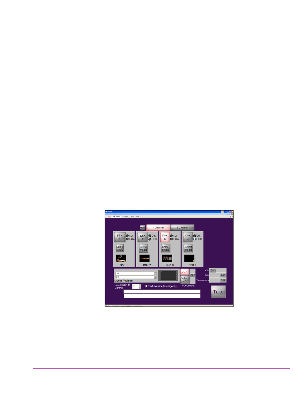
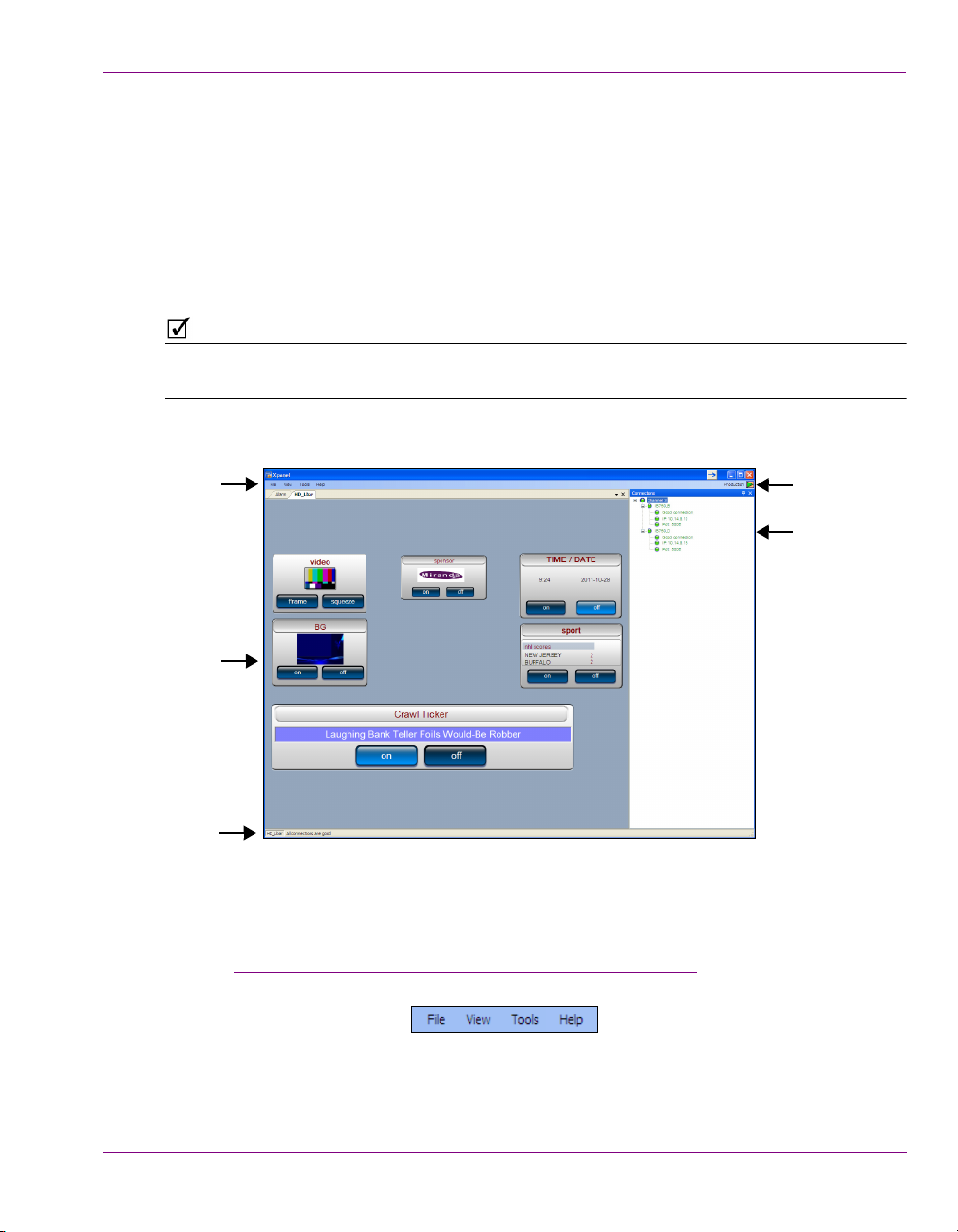
Figure 1-1. Xpanel allows to build custom control panels for on-air control of branding devices
Xpanel’s Design mode provides an environment for creating custom control panels that
meet your specific functional needs. Building a control panel in Xpanel basically involves
adding and configuring Xpanel’s control objects (widgets), which provides operators with
manual and automated controls for selecting and playing out branding graphics, as well as
video and/or audio media on a single-channel or multiple channels. For example, panels
may include controls for performing the following tasks:
• Cutting or fading up and down graphics on specific device keyers
• Viewing what media is currently keyed up on a specific device keyer
• Adjusting the gain, transparency and/or positioning media on device keyers
• Adjusting the levels and playing out voice-over audio, while ducking program audio
• Performing A/B mixing of incoming video sources using traditional cut and fade transitions
• Monitoring the health and alarms of connected devices
Xpanel User Manual 1-1
Page 10

Introducing Xpanel
If your control needs extend beyond the abilities of Xpanel’s objects, Xpanel also allows you
to add primitive objects, which can be configured to perform actions based on
playout/operator events or changes in tallies from the devices.
Xpanel also provides a station configuration, where channels and their associated devices
are defined. This simplifies panel creation by abstracting away device specifics and allows
for channel selection and ganged operation.
Once panels have been created and saved, they can be opened in Xpanel’s Production
mode and used by operators to control the on-air playout of graphics on the specified
channel branding devices.
1-2 Xpanel User Manual
Page 11

2 GETTING STARTED WITH XPANEL
NOTE
To help get you started using Xpanel, this chapter provides you with information about
installing and licensing the Xpanel software. Once installed, you must configure Xpanel to
recognize and actively connect with a local or remote server (Xmedia Server).
Information and instructions to help you set-up and familiarize yourself with Xpanel are
provided in the following sections:
Installation and licensing information” on page 2-2
• “
• “Starting Xpanel and connecting to the Xmedia Server” on page 2-3
• “Overview of Xpanel’s user interface” on page 2-6
For users who are unfamiliar with the Xmedia Server, it is the centralized asset
management server and license manager for Vertigo applications and devices. The Xmedia
Server can run locally as a service on the Xpanel workstation, or it can be a remote/central
Xmedia Server device on the same network as the workstation running Xpanel. In both
cases, the Xmedia Server contains the assets and the database that Xpanel uses to play
out graphics and voice-over audio on branding devices. See “
Xmedia Server” on page 2-3 for more information.
Connecting Xpanel to an
Xpanel User Manual 2-1
Page 12

Getting started with Xpanel
NOTE
Installation and licensing information
Xpanel is packaged with the Vertigo Suite software installation wizard. It can be installed as
part of the full installation or as an individual (standalone) component. In both cases, you
simply need to run the installation wizard on a workstation that is on the same network as
the Xmedia Server.
Information regarding the Vertigo Suite’s hardware and network requirements, as well as
instructions for installing and/or upgrading Xpanel, are available in the Vertigo Suite’s
Release Notes, which can be downloaded from the Miranda Support Portal
(http://www.miranda.com/support/product.php?name=Vertigo
Xpanel requires that a software application license be installed and validated on the Xmedia
Server that it is connected to (local or remote). Therefore, once Xpanel is installed, you must
contact the Miranda Technical Support team (support@miranda.com
key for Xpanel. Then you must apply and validate the license using the Vertigo Suite’s
License Manager, which stores the license on the Xmedia Server. Instructions for acquiring
and validating Xpanel’s application license are also provided in the Vertigo Suite’s Release
Notes.
Xpanel will not operate properly unless its connection to the Xmedia Server is active and a
valid license is present. See page 2-5
license errors.
for more information about resolving connection and
).
) to request a license
2-2 Xpanel User Manual
Page 13
Getting started with Xpanel
NOTE
NOTE
Starting Xpanel and connecting to the Xmedia Server
Open Xpanel by clicking VERTIGOXMEDIA>XPANEL from the Windows Start menu.
Each time Xpanel is opened, it verifies the connection to the server and the availability of
the Xpanel license. If both conditions are successful, then Xpanel opens and is ready to be
used. However, if either of these conditions is unsuccessful, an error message appears and
prompts you to resolve the situation.
The following sections describe how to resolve situations in which Xpanel cannot connect
to the Xmedia Server or find a valid license on startup.
Connecting Xpanel to an Xmedia Server” on page 2-3
• “
• “Resolving a license error on startup” on page 2-5
If Xpanel’s Startup options are configured to open in Production mode, a station
configuration must be loaded from the Xmedia Server before Xpanel can actually open.
See page 3-8 for more information.
Connecting Xpanel to an Xmedia Server
As a client application, Xpanel must always be connected to the Xmedia Server, which is
the centralized asset management server and license manager for Vertigo applications and
devices. The Xmedia Server can run locally as a service on the Xpanel workstation
(automatically installed as part of the Vertigo Suite installation) or it can be a remote/central
Xmedia Server device on the same network as the workstation running Xpanel. In both
cases, the Xmedia Server contains the assets and the database that Xpanel uses to play
out graphics and voice-over audio on branding devices.
While using Xpanel, the connection to the Xmedia Server must always be maintained (active),
otherwise you will be prevented from performing tasks that involve browsing or saving to the
Xmedia Server. Therefore, if for any reason the connection to the Xmedia Server fails
(disconnected), you must re-establish the connection before continuing to use Xpanel.
Common reasons for losing the connection are that the Xmedia Server or the machine
hosting Xpanel has lost its network connection (network is down, IP address has changed
or network cable disconnected), the Xmedia Server service has been stopped, or the
Xmedia Server machine has been shutdown or has crashed.
Xpanel User Manual 2-3
Page 14
Getting started with Xpanel
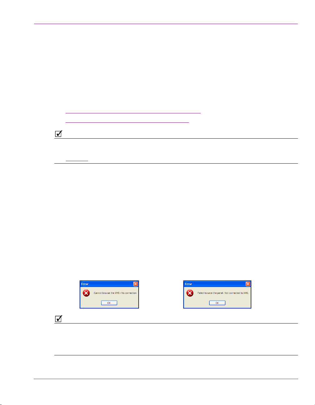
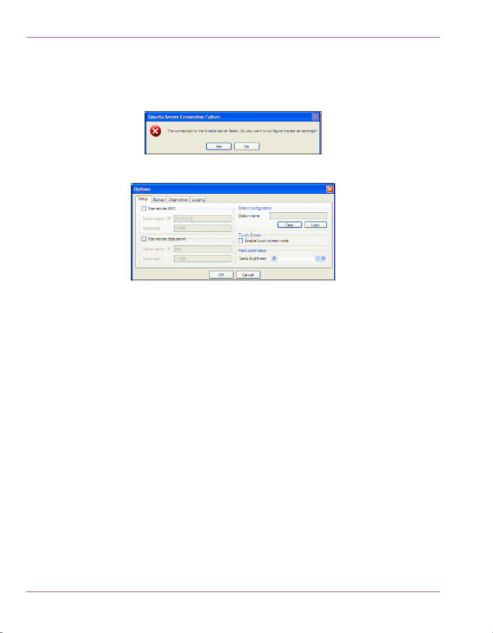
Resolving an Xmedia Server connection failure when opening Xpanel:
1. Open Xpanel by clicking V
If Xpanel cannot successfully connect to the Xmedia Server, the following error
message appears.
ERTIGOXMEDIA>XPANEL from the Windows Start menu.
2. Click Yes and Xpanel’s O
PTIONS window opens and displays the Setup page.
3. Verify Xpanel’s server connection configuration.
•If the U
SE REMOTE XMS check box is unchecked, Xpanel is configured to connect
to the local Xmedia Server, which was installed as part of the Vertigo Suite’s
installation package. Since Xpanel was unable to connect to the local Xmedia
Server on start up, you should verify that the Xmedia Server Service is actively
running (MS C
•If the U
ONTROL PANEL>VERTIGOXMEDIA XMEDIASERVER>SERVICE CONTROL).
SE REMOTE XMS check box is checked, Xpanel is configured to
connect to a remote Xmedia Server (i.e. central Xmedia Server) that is on the
same network as the Xpanel client workstation.
Since Xpanel was unable to connect to the remote Xmedia Server on start up, verify
the accuracy of S
ERVER NAME / IP setting and the SERVER PORT setting (14050). If
these settings are incorrect, make the appropriate edits.
If these settings are correct, verify that the machine hosting the Xmedia Server is
operating, that it is actively connected to the network, and its Xmedia Server Service
is actively running.
4. Click OK.
If you made any changes to the server settings, a message box appears and informs
you that you must restart Xpanel for the new server to take effect.
Xpanel should now open. If Xpanel still does not open, contact your system
administrator to help troubleshoot any possible network problems.
2-4 Xpanel User Manual
Page 15
Resolving a license error on startup
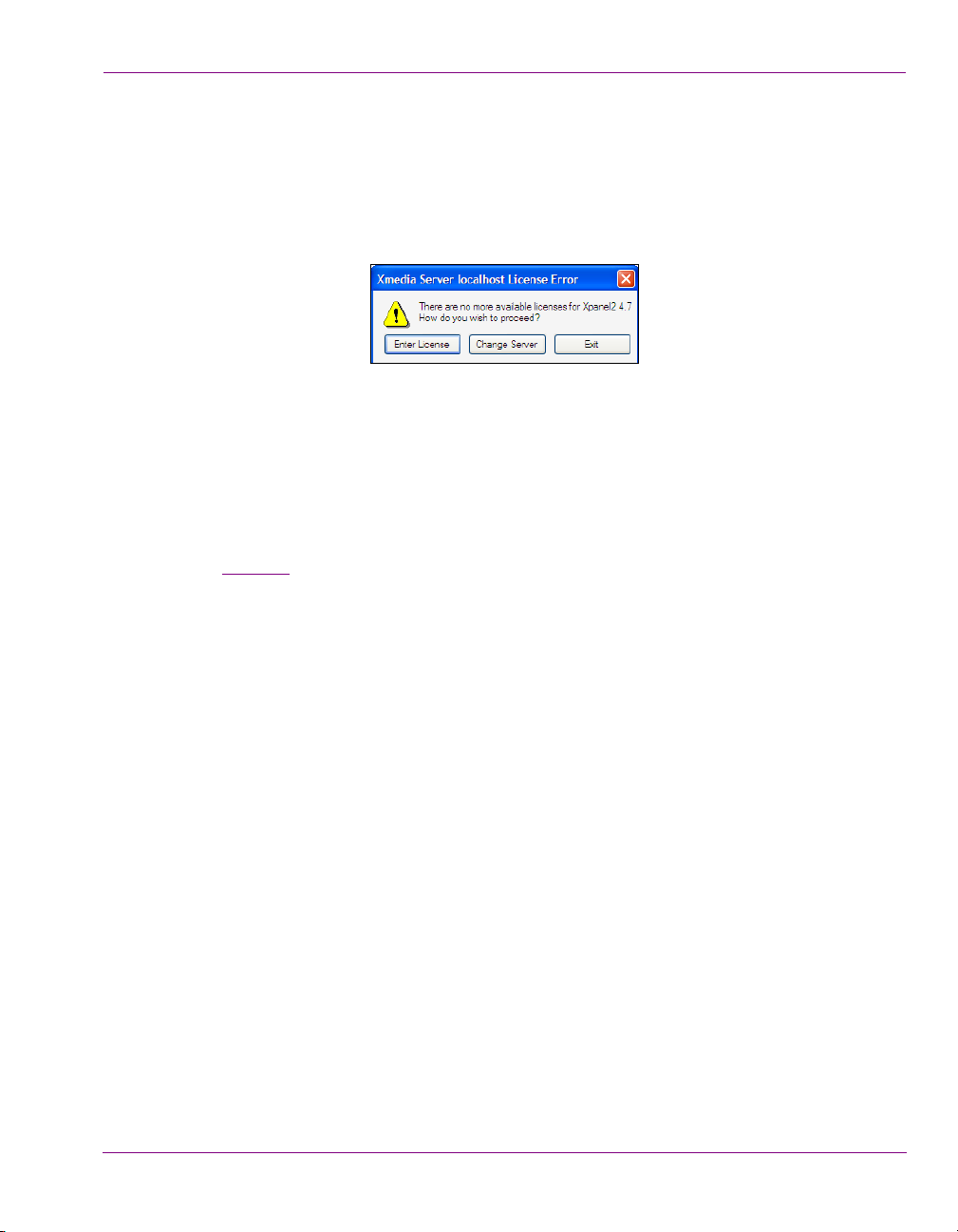
Resolving a license failure when opening Xpanel:
1. Open Xpanel by clicking VERTIGOXMEDIA>XPANEL from the Windows Start menu.
If Xpanel cannot successfully locate a valid Xpanel2 license on the Xmedia Server, the
following error message appears.
2. Evaluate and act according to the following:
• Click Enter License if you suspect that the cause of the license error is that the Xpanel2
license has not yet been installed and validated on the Xmedia Server. The License
Manager opens and you can follow the instructions in the Release Notes for acquiring and
installing a software license.
• Click Change Server if you suspect that the cause of the license error is that Xpanel is
connected to the wrong Xmedia Server (the license resides on another Xmedia Server).
Xpanel’s O
page 2-4 that describes how to resolve an Xmedia Server connection failure.
PTIONS window opens and displays the Setup page. Follow steps 3 and 4 on
Getting started with Xpanel
Xpanel User Manual 2-5
Page 16
Getting started with Xpanel
NOTE
NOTE
= currently in Design Mode
= currently in Production Mode
Overview of Xpanel’s user interface
Xpanel has two work modes: Design and Production. Since each mode is used for different
purposes, Xpanel’s user interface provides unique interface features in each mode.
Which mode Xpanel opens in depends upon the START IN PRODUCTION MODE setting in
Xpanel’s Startup options (see page 2-7).
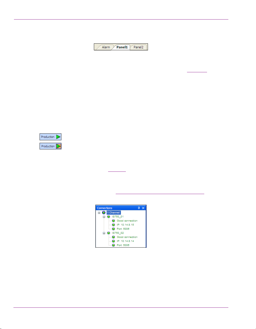
The P
RODUCTION MODE button located in the upper-right corner of the menu bar provides
an easy way to identify which mode Xpanel is currently in.
To switch between Design and Production mode:
• Select the V
Or,
• Press CTRL+P
Or,
• Click the P
In order to switch from Design mode to Production mode, a Station Configuration must be
loaded in Xpanel. See “Loading a station configuration” on page 3-8 for more information.
Also note that you may be prompted to enter a password when trying to switch from
Production mode to Design mode. See page 7-1 for more information.
The following sections provide a quick overview of the various user interface features, while
the remaining chapters provide more detailed descriptions within procedural contexts:
Design mode interface components” on page 2-7
• “
• “Production mode interface components” on page 2-9
The following sections provide instructions for managing and using Xpanel’s interface, like
opening/closing and docking/floating Xpanel’s Views, as well as how to zoom in/out or pan
across Xpanel’s canvas.
Opening and positioning Xpanel’s Views” on page 2-11
• “
• “Zooming in/out of the canvas” on page 2-13
• “Panning across the canvas” on page 2-13
IEW>PRODUCTION MODE menu command.
RODUCTION MODE button located in the upper-right corner of the menu bar.
2-6 Xpanel User Manual
Page 17
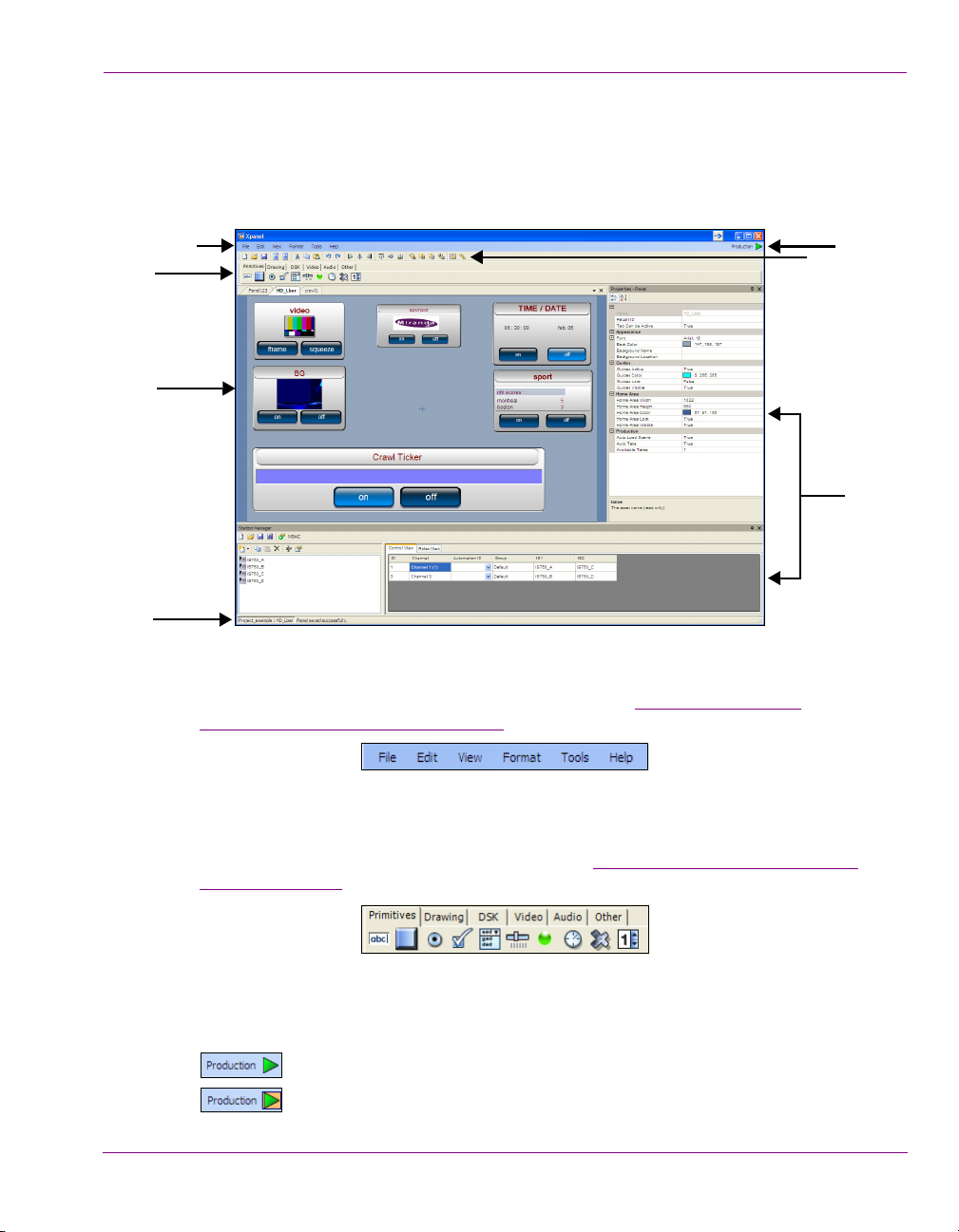
Design mode interface components
1
2
5
6
3
4
7
= currently in Design Mode
= currently in Production Mode
Design mode is Xpanel’s authoring environment that allows you to create and edit panels.
This section provides a brief functional description of the main interface components in
Design mode.
Getting started with Xpanel
Figure 2-1. An example of a panel open in Xpanel’s Design mode
1. Menus - These menu commands provide access to the settings and administrative
functions that are relevant to Xpanel’s Design mode. See “
A Quick reference to
Xpanel’s menus & toolbars” on page 8-1 for a description of each menu command.
2. Objects toolbar - Panels are created by adding control objects to the panel’s canvas and
setting their properties. The objects toolbar consists of six (6) thematic tabs that contain
object buttons that can be dragged onto the panel. The objects become the mechanism
by which operators control broadcast graphics. See “
Adding objects and primitives to a
panel” on page 4-6 for a description of each object.
3. Production mode button - Xpanel has two work modes: Design and Production.
Besides being a toggle button to switch from one mode to the other, the Production
mode button also identifies Xpanel’s currently mode.
Xpanel User Manual 2-7
Page 18

Getting started with Xpanel
4. Panel Canvas toolbar - When creating or editing a panel, the buttons in this toolbar
provide quick access to many of the administrative, editing and formatting functions
that are applied to the panel and its objects. See page 8-1
of each button in the toolbar.
5. Panel tabs and canvas - Each panel is created upon a canvas (workspace) where
objects are added and formatted into a functional control panel. Multiple panels can be
opened simultaneously, in which case a tab for each panel appears on top of the
canvas area. These panels can be stacked (default) or docked to the outer sides (sideby-side or up-down) by holding down the left-mouse button on a panel’s tab and using
the docking options. The panel’s canvas also has properties that determine its
appearance and behavior. The following sections provide information and instructions
on using the panel’s canvas:
Opening panels or projects” on page 4-2
• “
• “Configuring the panel’s properties” on page 4-4
• “Zooming in/out of the canvas” on page 2-13
• “Panning across the canvas” on page 2-13
6. Views - Xpanel provides several different views, which are mainly software tools used
in the creation and support of panels. As described on page 2-11, the views can be
docked panels or floating windows, which can be displayed or hidden.
The following views are available in Xpanel:
• Properties: Panels are created by adding objects to the panel’s canvas and setting
their properties. When an object, or the canvas itself, is selected, its current
properties settings are displayed in the Properties view. See page 4-4
for more information.
• Object List: A list of the objects that are currently on the panel. Right-clicking the
object allows you to select the Set as a drag & drop default and Reset the drag
& drop default commands.
• Asset Browser: The Asset Browser allows you to browse and preview the Panels,
Images, Data schemas that are stored on the Xmedia Server. Panels can be
opened directly from the Asset Browser, images can be dragged onto the canvas
and new data schemas can be created and linked to objects.
• Action Editor: All of the objects in Xpanel, except for primitives, are defined with a
specific purpose or function. For example, the DSK object is a toggle button for keying
up or down a graphic. The Action Editor allows you to add to the functionality of
standard Xpanel objects or define the functionality of primitive objects by configuring
and associating the objects with a set of actions to occur on an event. See “
events and actions to primitives and objects” on page 5-1 for more information.
• Script Editor: The Script Editor allows you to create or edit custom VB scripts to
provide more complex functionality to actions associated with Xpanel objects.
• Station Manager - Xpanel’s Station Manager allows you to define the devices on the
network and then create a station configuration, which groups the devices into channels.
Creating and loading a station configuration” on page 3-1 for more information.
See “
• RCP List - The RCP List allows you to configure the RCP-BR devices on your network.
for a functional description
and page 4-7
Adding
2-8 Xpanel User Manual
Page 19
7. Status bar - The Status bar displays the name of the panel/project that is currently
NOTE
1
2
4
5
3
open in Xpanel. It also displays the status of a task that was just performed in Xpanel,
like successful completion saving a panel or exporting assets.
Production mode interface components
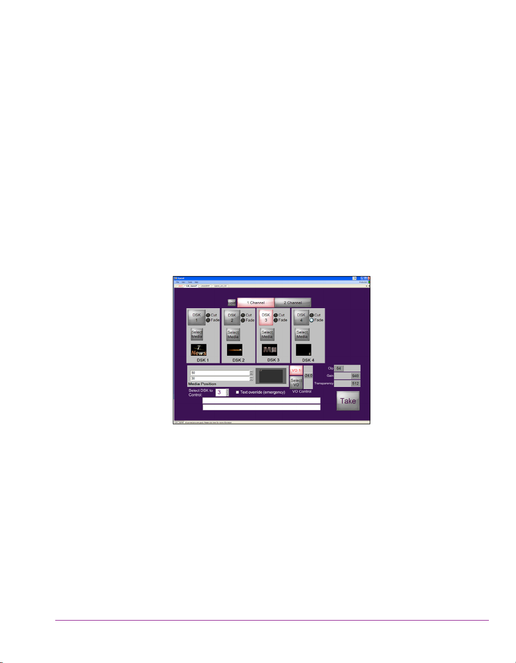
Production mode is Xpanel’s playout environment that allows you to load and use panels to
control playout devices.
Production mode makes the panels live. Therefore, if your intent is to explore the interface
or test the panel’s behavior, ensure that the selected devices are not live on air.
This section provides a brief functional description of the main interface components in
Production mode.
Getting started with Xpanel
1. Menus - Located along the top of the interface, these menu commands provide access
Xpanel User Manual 2-9
2. Panels & Tabs - In Production Mode, opened panels are displayed on the main area
Figure 2-2. An example of a panel open in Xpanel’s Production mode
to Xpanel’s setting and administrative functions that are relevant to Production mode.
A Quick reference to Xpanel’s menus & toolbars” on page 8-1 for a description of
See “
each menu command.
of the user interface. Multiple panels can be displayed at the same time, in which case
a tab appears on top of each panel. When multiple panels are open, they can be
Page 20
Getting started with Xpanel
= currently in Design Mode
= currently in Production Mode
stacked (default) or docked to the outer sides (side-by-side or up-down) by holding
down the left-mouse button on a panel’s tab and using the docking options.
In Production mode, operators can interact with the panel’s objects (i.e. click buttons,
set text, select media... etc.), but they cannot edit the panel or its objects.
When the S
HOW ALARM TAB IN PRODUCTION MODE setting is enabled (see page 7-11),
the Alarms panel is loaded and displays the status of the device alarms and health
meters for the connected devices.
3. Status bar - The Status bar displays the name of the panel/project that is currently
open in Xpanel. It also displays the connection status of the devices associated with
the panel. You can click on the status bar to open the Connections Monitor view.
4. Production mode button - Xpanel has two work modes: Design and Production.
Besides being a toggle button to switch from one mode to the other, the Production
mode button also identifies Xpanel’s currently mode.
When Xpanel is intended to be used in Production mode only, it can be configured to
open in Production mode and the ability to switch to Design mode can be restricted
using a password protection. See page 7-1
for more information.
5. Connection Monitor - The Connection Monitor displays the connection status and
properties for the channels and devices that are assigned to the objects on the panel(s)
that are currently open in Xpanel. See “
Monitoring device connectivity” on page 7-9 for
more information.
2-10 Xpanel User Manual
Page 21
Opening and positioning Xpanel’s Views
NOTE
Design mode
Production mode
As described on page 2-7 and page 2-9, Xpanel provides you with several views, which are
browsers and tools for building, configuring and monitoring the exact appearance and
behavior of the panel and its objects.
To avoid cluttering Xpanel’s interface and allow you to personalize the layout of your
workspace, the views are hidden by default. The following sections describe how once the
views are opened, they can be in the following states: floating, docked, hidden, pinned, or
tabbed.
For users, who are unfamiliar with the behaviors of docked and floating UI panels, the
following topics describe the basic tasks for controlling the layout of Xpanel views:
Opening and closing views” on page 2-11
• “
• “Floating versus docked views” on page 2-12
• “Positioning docked views” on page 2-12
• “Auto-hidden and pinned views” on page 2-13
Views and their layouts persist after being switched between Xpanel’s two modes, as well
as across Xpanel sessions.
Getting started with Xpanel
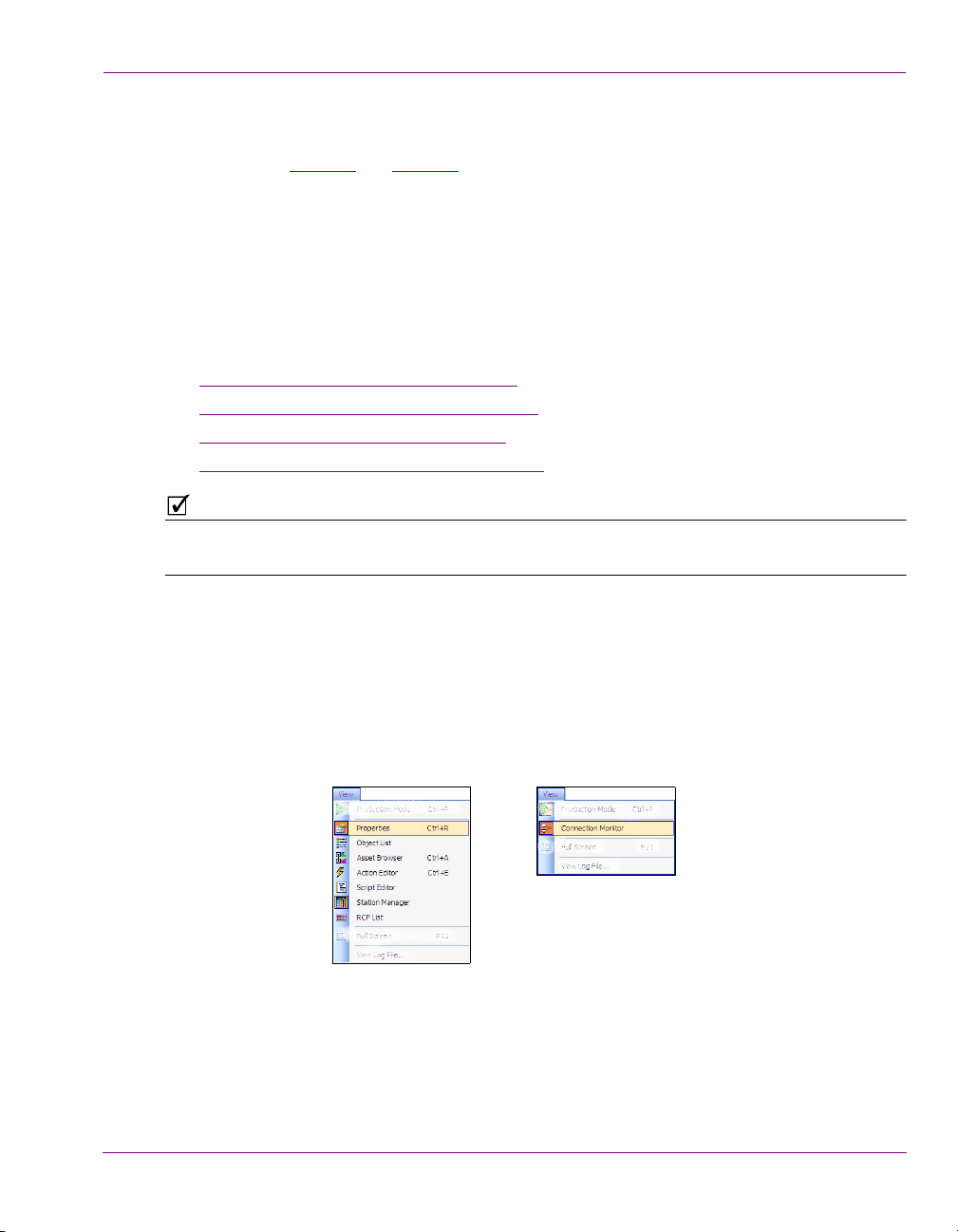
Opening and closing views
By default, the views are hidden from Xpanel’s main interface since they are used during
various stages panel building and usage.
• To open a view in either Design or Production mode, simply select the V
then choose one of the views. Alternatively if the view has one, you can use the view’s
keyboard shortcut.
• To close a view, either click the X button in the top-right corner of the view, or select
V
IEW menu and the view’s name once again or use the view’s keyboard shortcut.
Xpanel User Manual 2-11
IEW menu and
Page 22
Getting started with Xpanel
Stacked
single panel with multiple tabs
(side-by-side)
Floating versus docked views
Views can be docked to the outer sides of the Xpanel interface or float as independent
windows. When a view is opened, it will appear in the state and position that it was last
closed in. Double-click the view’s title bar to toggle between docked and floating states.
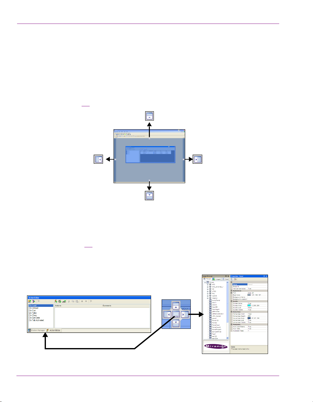
Positioning docked views
Views can be docked along the outer sides of the Xpanel interface. When you hold down the
mouse’s left button over a view’s title bar, docking guides appear to indicate where the view can
be docked (figure 2-3
). To dock the view, simply drag the view’s title bar onto the dock guide.
Figure 2-3. Docking views to the outer sides of the Xpanel interface
Two or more docked elements can be docked in the same location by combining them into
a single panel with multiple tabs, or by stacking them.
When you drag a view by its title bar (or tab) on top of another view, a multi-position docking
tab appears (figure 2-4
new view will be stacked on top, below, or beside the current view in that location. If you
drop the view onto the center guide or onto the docked view’s title bar, the two views
combine into a multi-tab view.
Figure 2-4. Views sharing the same location (multi-tab or stacked)
2-12 Xpanel User Manual
). If you drag and drop the view onto one of the four outer guides, the
Page 23

Auto-hidden and pinned views
By default, docked views are pinned to their location, meaning that appear when opened
and stay displayed until they are closed. Clicking the A
bar changes the view’s state from pinned to auto-hidden, which automatically hides the view
on the side leaving only a tab. The view is not closed, just hidden. To make the view reappear, simply hover the mouse pointer over the view’s tab and click within the view. Each
time you click outside of the view however, the view automatically hides.
To change the view from auto-hidden to pinned, simply click A
Zooming in/out of the canvas
Whether Xpanel is in Design mode or Production mode, you may want to see a panel’s
objects in greater detail by zooming in on the canvas. Similarly, you can get an expanded
or distanced view of the canvas by zooming out of the canvas.
There are several methods for zooming in or out of the canvas:
Mouse wheel
• Click anywhere on the canvas and roll the mouse wheel forward to zoom in
or roll the mouse wheel backward to zoom out.
Alt key sequence
• Hold down the ALT key and the right mouse button, then drag a rectangle
around the specific area that you want to zoom in on.
Home key / Spacebar
• Press the H
the Xpanel’s current workspace’s frame.
OME key or spacebar on your keyboard to completely fit the canvas within
Getting started with Xpanel
UTO-HIDE button in the view’s title
UTO-HIDE button again.
Panning across the canvas
When you zoom in on a portion of the canvas, you may not see certain areas of the canvas.
Rather than zooming out and sacrificing the current zoomed view, you can maintain the
zoom scale by panning across the canvas to the area that was otherwise outside of the
window’s display.
To pan across the canvas:
Holding down the ALT key and press the arrow keys on your keyboard to move the canvas
toward the desired location.
Xpanel User Manual 2-13
Page 24

Getting started with Xpanel
2-14 Xpanel User Manual
Page 25
3 CREATING AND LOADING A STATION
CONFIGURATION
Before using Xpanel to create panels and control devices, you must ensure that the devices
that the panels will control are listed in Xpanel’s Station Manager, which means that they
are associated with the Xmedia Server. If a device is not listed, you must add the device’s
configuration profile to the Xmedia Server.
Once the devices are listed in the Station Manager, you must create a station configuration,
which is a set of channel definitions that group the devices. The station configuration is then
saved to the Xmedia Server and loaded in Xpanel so that you can set panel objects to
control specific channels or devices.
The following sections provide instructions for how to create and load station configurations:
Adding a device to the Station Manager” on page 3-2
• “
• “Creating and saving a new station configuration” on page 3-4
• “Adding a channel to the station configuration” on page 3-5
• “Loading a station configuration” on page 3-8
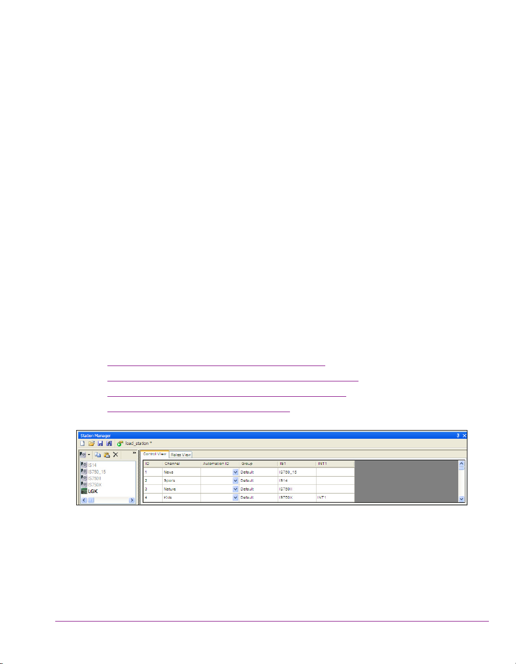
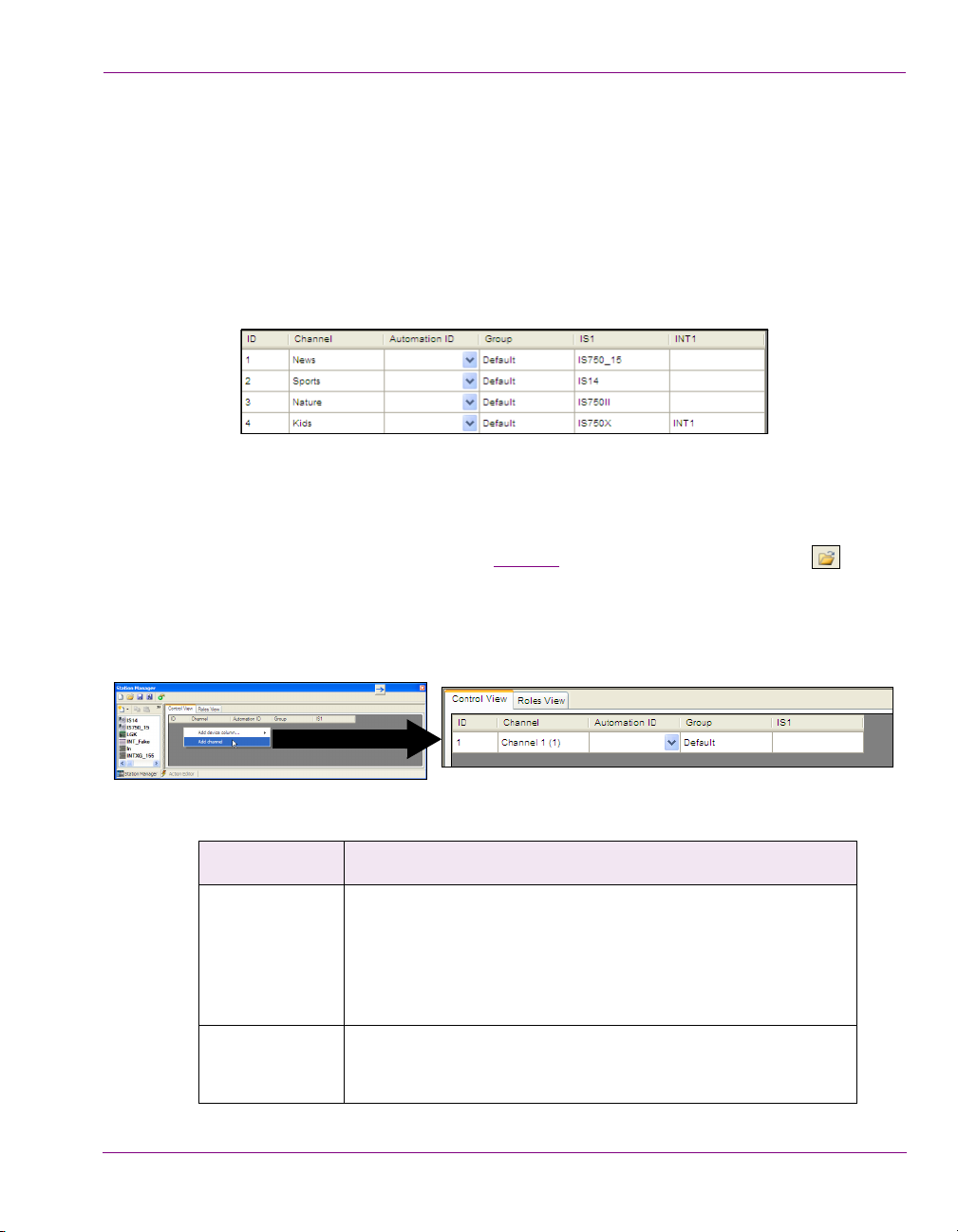
Figure 3-1. Xpanel’s Station Manager displays a station configuration that contains channels
Xpanel User Manual 3-1
Page 26
Creating and loading a station configuration
NOTE
NOTE
Adding a device to the Station Manager
Xpanel’s Station Manager identifies the output devices that are associated with the Xmedia
Server and therefore can be controlled by the panels created in Xpanel. If a device is not
listed in the Station Manager, you can add the device to the Xmedia Server by creating a
profile that defines the device’s connection and communication properties.
The following device types are supported and can be added to Xpanel’s Station Manager.
• Imagestore
•LGK
•DSK
• Intuition
• Intuition XG (Remote/Central Xmedia Server only)
• Vertigo XG (Remote/Central Xmedia Server only)
•HMP
•Xftp
• Xpublish Agent
Since several applications in the Vertigo Suite are capable of defining devices on the
Xmedia Server using the Device Manager, it is possible that the device configuration
profiles of some of the devices on your network are already present in the Station Manager.
As such, when you open Xpanel and it is connected to the Xmedia Server, the devices that
already exist in the Xmedia Server will appear in Xpanel’s Station Manager.
To add a new device configuration to the Xmedia Server using the Station Manager:
1. Launch Xpanel’s Station Manager by selecting the VIEW>STATION MANAGER menu
command.
2. Click the N
The D
INTUITION XG and VERTIGO XG devices are only listed if Xpanel is configured to connect to
a remote/central Xmedia Server. See “
Server” on page 2-3 for more information.
3-2 Xpanel User Manual
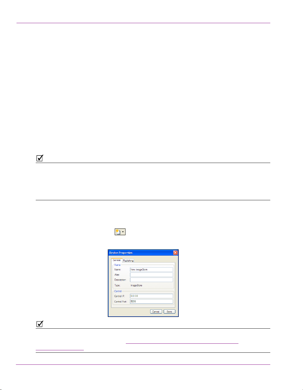
EW DEVICE button and select the type of device from the drop-down list.
EVICE PROPERTIES window appears.
Starting Xpanel and connecting to the Xmedia
Page 27
Creating and loading a station configuration
NOTE
3. Complete the following fields on the Device Properties’ General tab:
• N
AME: The name of the device.
LIAS: An optional field that provides an alternative name for the device on your network.
• A
ESCRIPTION: An optional field that lets you identify the device using a meaningful label. This
• D
is helpful for distinguishing similar devices at your facility.
ONTROL IP: The network location (IP address) or hostname of the selected device. The host
• C
must be available on the network.
ONTROL PORT: The networking port that serves as a channel for sending commands to and
• C
from the device.
4. Select the Publishing tab and complete the following fields:
UBLISH IP: The network location (IP address) or hostname of the of the machine to which
• P
assets are published when publishing to the selected device. This is usually set to the
same address as the Control IP. Note that the host must be available on the network.
UBLISH PORT: The networking port that serves as a channel for publishing assets.
• P
Typically, this value is set to 5001.
5. Click S
AVE.
The device is added to the device list in the Station Manager.
Notice that the image on the NEW DEVICE button has changed and now displays the icon
representing the device type of the last device added (e.g. for Imagestore devices).
This provides a shortcut to add a new device of that same type. If you want to add a new
device that is a different type, click the drop-down list arrow portion of the N
EW DEVICE
button and select the new device type.
Another method for quickly adding a new device is to select an existing device and use the
OPY DEVICE and PASTE DEVICE buttons in the Device List’s toolbar to create a copy
C
of the device. Select the copy of the device and click the D
EVICE PROPERTIES button .
Edit the device’s properties in the DEVICE PROPERTIES window and click SAVE.
Xpanel User Manual 3-3
Page 28
Creating and loading a station configuration
NOTE
NOTE
Creating and saving a new station configuration
The station configuration determines which channels and devices are available to be
controlled by the panels created in Xpanel.
The following procedures describes how to create a station configuration by assigning
devices from the Station Manager’s Device List to the channels and then saving the station
configuration to the Xmedia Server.
Although station configurations are saved to the Xmedia Server, they can only be used on
instances of Xpanel that are connected to that server. The station configuration cannot be copied
or exported to another server.
To create and save new station configuration:
1. Launch Xpanel’s Station Manager by selecting the V
command.
2. Click the N
The channel configurator section of the Station Manager is empty.
3. Add a channel to the channel configurator section of the Station Manager and assign
devices to the channel. (see “
4. Save the station configuration by clicking the S
Manager’s toolbar.
The S
5. In the N
6. The AUTHOR field is automatically filled in with the current login user’s name, but it can
be edited.
7. The D
8. Click S
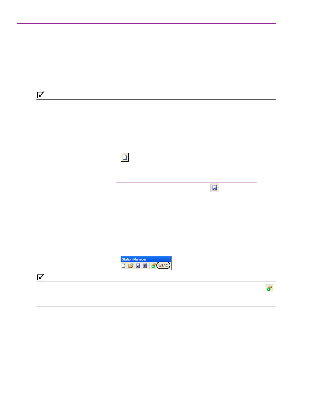
Since the station is open, its name now appears in the Station Manager’s toolbar.
EW STATION button from the Station Manager’s toolbar.
Adding a channel to the station configuration” on page 3-5).
AVE STATION CONFIGURATION window appears.
AME field, specify a name for the Station Configuration.
ESCRIPTION field is optional and lets you identify the station using a meaningful label.
AVE.
IEW>STATION MANAGER menu
AVE STATION button in the Station
An alternative to using the SAVE STATION button is to click the SAVE AND LOAD STATION button
in the Station Manager’s toolbar. See “Loading a station configuration” on page 3-8 for more
information.
3-4 Xpanel User Manual
Page 29
Creating and loading a station configuration
Adding a channel to the station configuration
The station configuration defines a set of channels, which identify the devices that make up
the transmission path of a playout channel. A channel can consist of a single device or
multiple devices that work together (i.e. an Imagestore device as the down-stream keyer for
an Intuition XG device).
Each station configuration must contain at least one channel. The following procedure
explains how to add a channel to the station configuration, as well as how to associate
devices with the channel.
Figure 3-2. A typical channel setup in a station configuration
To create a new channel in Xpanel’s Station Manager:
1. Launch Xpanel’s Station Manager by selecting the V
command.
2. Create a new station configuration (see page 3-4
in the Station Manager’s toolbar to open an existing station configuration.
3. Right-click in the channel configurator section of the Station Manager and select the
DD CHANNEL command.
A
A new channel row is immediately added to the channel configurator.
IEW>STATION MANAGER menu
) or click the OPEN STATION button
The following table defines a channel’s default columns:
Column name Description
ID An ID number associated with the channel that determines its order
in the Station Manager’s channel configurator. You can edit the ID
number by selecting the cell and typing a new number. When you
click away or press Enter, the channel is automatically sorted in the
Station Manager according to the ID number. Note that each
channel’s ID number must be unique.
Channel The channel’s name. You can rename the channel by clicking in the
C
HANNEL cell and typing a new name, or by right-clicking on the
channel and selecting the R
ENAME CHANNEL command.
Xpanel User Manual 3-5
Page 30
Creating and loading a station configuration
NOTE
Column name Description
Automation ID The Automation ID was once used for schedule-based publishing,
but it has since been deprecated.
Group If all of the channels are left as D
EFAULT, then they will all be shown
in one view on the Channel Selector. This works well if there are
only a few channels, but if you want to show the channels in groups,
then entering a Group name will separate the channels in the
Channel Selector into their appropriate groups.
IS1 By default, new channels contain a device column called IS1, which
represents an Imagestore device in the channel. If the channel that
you want to define does not contain an Imagestore device, remove
this device column by right-clicking on the column’s heading and
selecting the R
EMOVE DEVICE COLUMN command.
If however the channel will contain an Imagestore device, drag the
appropriate Imagestore device from the Station Manager’s Device
List and drop it onto the channel’s IS1 cell. Another way to assign a
device to a channel’s device column is to right-click within the
recipient cell and select the A
DD DEVICE command, which expands
to display all of the available devices from the Device List of that
device type. Select a device from the list.
The scope of this user manual is limited to explaining the definition of channels on the
Control View tab. Please contact Miranda’s Technical Support for questions regarding the
Station Manager’s Roles View tab.
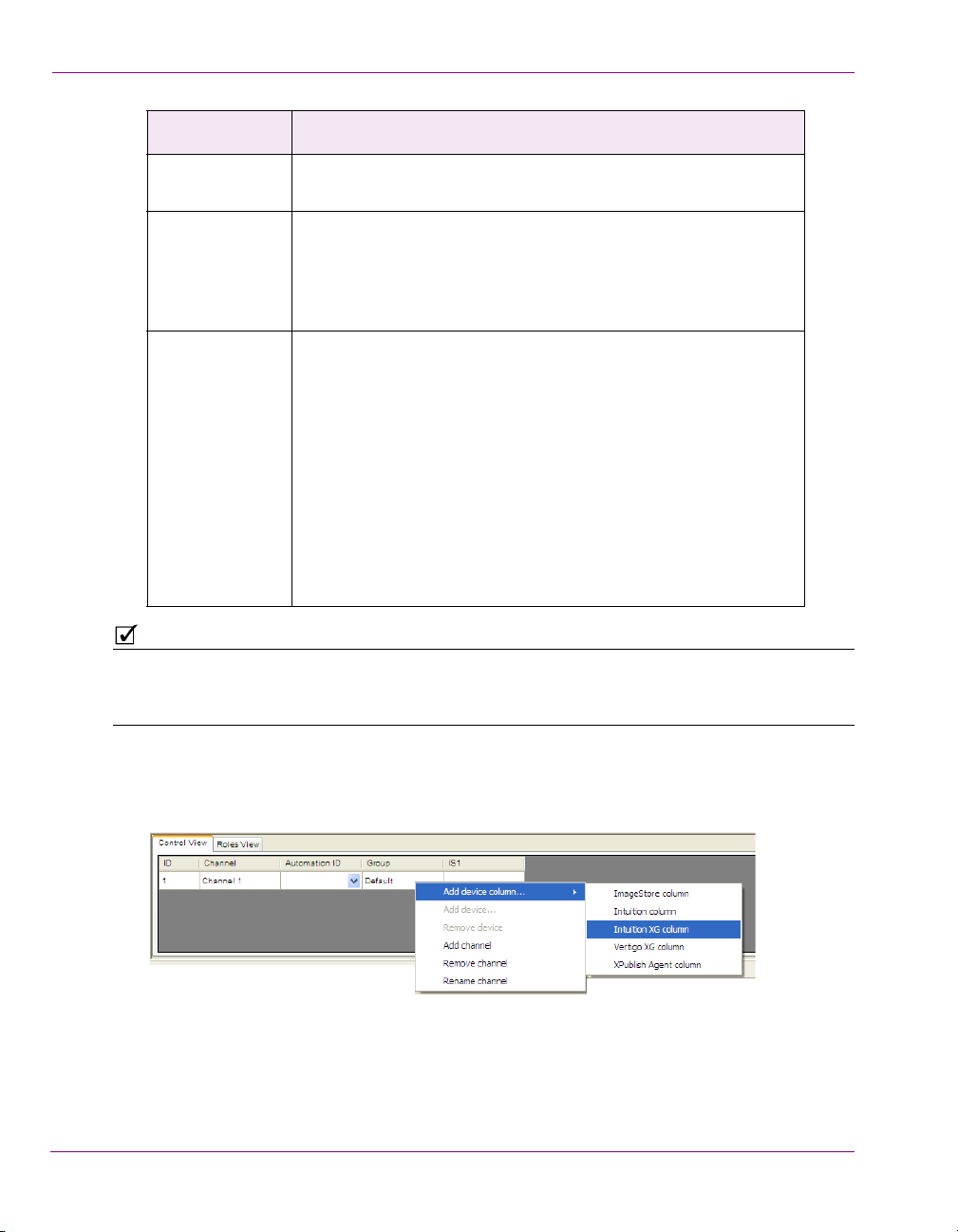
4. Add an additional device column for each device in the channel.
Right-click on the channel and select the ADD DEVICE COLUMN command, as well as the
appropriate device type.
3-6 Xpanel User Manual
Page 31

Creating and loading a station configuration
NOTE
5. Add devices to the device columns by dragging the appropriate devices from the
Station Manager’s Device List and dropping them onto the channel’s device columns.
A device can only be assigned to one channel. When a device is added to a channel, the
device becomes disabled (grey) in the Station Manager’s Device List to indicate that it is
already dedicated to a channel. If that device is required by another channel, you must first
remove it from its present channel. See “
on page 3-7.
Removing a device assignment from a channel”
6. Save the channel to the station configuration by clicking the S
in the Station Manager’s toolbar.
AVE STATION button
Removing a device assignment from a channel
A device can only be assigned to one channel, so if that device is required by another
channel, you must first remove it from its present channel.
To remove a device assignment from a channel:
1. Right-click on the channel cell that contains the device and select the R
command.
2. Click the S
AVE STATION button in the Station Manager’s toolbar.
Removing a channel from a station configuration
To remove a channel from a Station Configuration:
1. Right-click anywhere within the channel and select the R
2. Click YES when prompted to confirm that you want to remove the channel.
The channel is immediately removed from the station configuration.
3. Click the S
AVE STATION button in the Station Manager’s toolbar.
EMOVE CHANNEL command.
EMOVE DEVICE
Xpanel User Manual 3-7
Page 32

Creating and loading a station configuration
Loading a station configuration
When creating or editing panels in Xpanel’s Design mode, a station configuration must be
loaded so that you can set panel objects to control specific channels or devices.
Also note that a station configuration must be loaded in Xpanel in order to access Xpanel’s
Production mode. Whether switching from Design mode to Production mode or if Xpanel’s
Startup options are configured to open in Production mode, Xpanel will not open Production
mode until a station configuration is loaded first. Select Yes to open Xpanel’s Options window
and following the instructions below for loading a station configuration.
The two methods for loading a station configuration are described below.
Loading a station configuration using Xpanel’s Options:
1. Select the T
The Options window appears.
OOLS>OPTIONS menu command.
2. Select the S
The O
3. Select the station configuration that you want to load and click O
The station configuration’s name now appears in the S
ETUP tab and click the LOAD button in the Station configuration section.
PEN STATION CONFIGURATION window appears.
PEN.
TATION NAME field in the OPTIONS
window.
4. Click OK.
3-8 Xpanel User Manual
Page 33

Creating and loading a station configuration
Loading a station configuration using Xpanel’s Station Manager:
1. Create a new station configuration (see page 3-4
) or click the OPEN STATION button
in the Station Manager’s toolbar to open an existing station configuration.
2. Click the S
AVE AND LOAD STATION button in the Station Manager’s toolbar.
3. Click OK when prompted to confirm that you want to set Xpanel to use the open
configuration.
Xpanel saves the open station configuration and loads it as Xpanel’s current station in
Xpanel’s O
PTIONS settings (SETUP tab > STATI ON NAME).
Xpanel User Manual 3-9
Page 34

Creating and loading a station configuration
3-10 Xpanel User Manual
Page 35

4 BUILDING AND EDITING PANELS
Xpanel’s Design mode provides the workspace and tools for building control panels that
allow operators to interact with and control the preview and/or on air playout of graphics.
The following sections provide a generic workflow and introduces you to the control objects
that are used to create control panels in Xpanel:
Opening panels or projects” on page 4-2
• “
• “Configuring the panel’s properties” on page 4-4
• “Adding objects and primitives to a panel” on page 4-6
• “Configuring an object’s properties” on page 4-7
• “Creating a Channel Selector” on page 4-34
• “Positioning and formatting objects on the canvas” on page 4-36
• “Saving a panel” on page 4-47
• “Adding panels to a project” on page 4-48
• “Exporting and importing a panel or project” on page 4-49
• “Closing panels” on page 4-51
Xpanel User Manual 4-1
Page 36

Building and editing panels
Opening panels or projects
Xpanel’s Design mode allows you to build new panels and/or edit panels that already exist
on your system.
Xpanel allows you to save multiple panels into one grouped file called a project, which has the
extension .xpp and is not saved on the Xmedia Server, but locally instead. Each individual
panel must already have been saved to the Xmedia Server before becoming part of a project.
When the project is opened, all of the panels belonging to the project load in Xpanel.
The following sections provide instructions for opening a new or existing panels and
projects in Xpanel:
Opening a new panel” on page 4-2
• “
• “Opening an existing panel or project” on page 4-3
Opening a new panel
When Xpanel’s Startup options are not configured to auto-load a panel or project (see page
7-4), each time Xpanel is opened a new panel with a default name of PANEL1 is
automatically created. You can use this empty panel to build a new panel.
If you are already working within Xpanel and you would like to create a new panel, perform
one of the following to open a new panel:
• Select the F
Or,
• Press CTRL+N
Or,
• Click the N
The new panel opens with an empty canvas and a tab that displays a default panel name
(i.e. Panel1).
ILE>NEW menu command.
EW button located in the Xpanel canvas’ toolbar.
Figure 4-1. A new panel in Xpanel’s Design mode
4-2 Xpanel User Manual
Page 37

Opening an existing panel or project
NOTE
When Xpanel’s Startup options are configured to auto-load a panel or project (see page 7-4),
each time Xpanel is opened, the panel or project specified will automatically be loaded and
displayed in Xpanel.
You can also access and open existing panels and projects using the following methods:
To open an existing panel:
• Select the FILE>OPEN menu command or press Ctrl+O. The OPEN PANEL window
appears. Navigate to and select the panel. Click O
Or,
• Click the O
appears. Navigate to and select the panel. Click O
Or,
• Open the A
and then double-click its name.
To open an existing project:
• Select the FILE>PROJECT>OPEN menu command. The OPEN PROJECT window
appears. Navigate to and select the Xpanel project file (*.xpp). Click OPEN.
PEN button in the Design mode toolbar. The OPEN PANEL window
SSET BROWSER (Ctrl+A) and select the PANELS tab. Navigate to the panel
Building and editing panels
PEN.
PEN.
Panels and projects created on another Vertigo Suite system can be imported into the
system and then opened using the above methods. See “Exporting and importing a panel
or project” on page 4-49 for more information.
Xpanel User Manual 4-3
Page 38

Building and editing panels
Configuring the panel’s properties
Xpanel’s Design mode allows you to view and edit properties that determine the appearance
and behavior of the panel and its components (i.e. canvas, home area, guides... etc.).
To display the panel’s properties:
• If Xpanel’s Properties view is not open, right-click anywhere on the panel (i.e. the canvas
or home area, not on an object) and select the P
opens and displays the panel’s current properties settings.
Or,
• If Xpanel’s Properties view is already open, select anywhere on the panel (i.e. the canvas or
home area, not on an object) and the panel’s current properties settings are displayed.
ROPERTIES command. The Properties view
Property category Properties and description
• N
AME: The panel’s current name. This is a read-only field. See
“Renaming a panel” on page 5-4 for instructions on how to rename
a panel.
ECALL ID: Allows you to set an ID that can be entered into the
• R
Recall ID field in Production mode to instantly call up the panel.
AB CAN BE ACTIVE: Set to FALSE if the panel should never become
• T
the current active panel.
4-4 Xpanel User Manual
Page 39

Building and editing panels
Property category Properties and description
Appearance The Appearance properties allow you to change the color of the panel’s
canvas or display an image as canvas’ background.
ONT: Sets the default font properties (style, size...etc.) for Text
• F
objects added to the panel’s canvas.
ACK COLOR: Determines the solid color of the panel canvas’
• B
background.
ACKGROUND NAME: Allows you to select an image asset as the
• B
canvas’ background rather than a solid background color and
displays the image asset’s name.
ACKGROUND LOCATION: Allows you to select an image asset as
• B
the canvas’ background rather than a solid background color and
displays the image asset’s location.
Guides Guides are virtual lines that are superimposed over the panel’s canvas
in Design mode. You can use the guides as a reference when arranging
or aligning objects. While the guides are activated using the
FORMAT>ADD GUIDES menu command, the Guides properties can be
used to set the visibility, color and whether or not the guides are locked
to a specific position.
UIDES ACTIVE: Determines whether or not the guides will have
• G
snap-to functionality.
UIDES COLOR: Determines the color of the guides.
• G
UIDES LOCK: Determines whether or not the guides will be locked
• G
in place or available for repositioning.
UIDES VISIBLE: Determines whether or not the guides are visible.
• G
Home Area The Home Area is the area surrounding the panel’s canvas. The Home
Area properties allow you to set the size, color and visibility of the home
area.
OME AREA WIDTH: Determines the width of the home area.
• H
OME AREA HEIGHT: Determine the height of the home.
• H
• H
OME AREA COLOR: Determines the color of the home area.
OME AREA LOCK: Determines whether or not the home area can
• H
be resized by dragging from its edges and corners.
OME AREA VISIBLE: Determines whether or not the home area will
• H
be visible.
Production • A
UTO LOAD SCENE: Determines whether or not to automatically
load the scene.
UTO TAKE: Determines whether or not to automatically take the
• A
panel to air.
VAILABLE TAKES: Sets the number of takes that can be taken to air
• A
with the panel.
Xpanel User Manual 4-5
Page 40

Building and editing panels
NOTE
Adding objects and primitives to a panel
Panels are built by adding objects to the panel’s canvas. Most of the objects are graphical
controls or displays that have a specific purpose or logic associated to them. As such, once
the object is added to the panel’s canvas, you simply have to set the object’s properties (see
Configuring an object’s properties” on page 4-7).
“
Unlike the other objects, primitives are raw graphical controls or displays that have limited
or no logic associated to them. Besides having to set a primitives properties, you must also
program its logic by associating specific actions to events using the Action Editor (see
“Adding events and actions to primitives and objects” on page 5-1).
The objects and primitives that can be used to build a panel are organized thematically in
the Objects toolbar in Xpanel’s Design mode.
The following sections provide a brief introduction to each object and primitive:
Primitive objects and their properties” on page 4-8
• “
• “Drawing objects and their properties” on page 4-13
• “DSK objects and their properties” on page 4-15
• “Video objects and their properties” on page 4-21
• “Audio objects and their properties” on page 4-24
• “Other objects and their properties” on page 4-29
To add an object or primitive to the panel’s canvas:
1. Open a panel in Xpanel’s Design mode.
2. Select a tab from the Objects toolbar.
3. Perform one of the following:
• Select the object’s or primitive’s icon and then drag and drop it onto the canvas.
Or,
• Hold down the left mouse button and drag to set the desired size. The
object/primitive is added to the panel when you release the mouse button.
If an existing panel contains objects that would like to include on a new panel, you can avoid
starting from new by copying objects from one panel and pasting them onto the new panel.
Note that all of the objects’ property settings are also brought over.
4-6 Xpanel User Manual
Page 41

Configuring an object’s properties
NOTE
In this example, the Channel Selector’s
current properties settings are displayed
in the Properties view.
Once an object or primitive has been added to the panel’s canvas, you must configure its
properties to determine its appearance and specific behavior.
To display an object’s properties:
• If Xpanel’s Properties view is already open, select the object on the canvas and the
object’s current properties settings are displayed.
• If Xpanel’s Properties view is not already open, perform one of the following:
• Right-click on the object and select the P
Properties view opens and displays the object’s current properties settings.
Or,
• Select the object and then open the Properties view by selecting the
IEW>PROPERTIES menu command or by pressing CTRL+R. The Properties
V
view opens and displays the object’s current properties settings.
ROPERTIES command. The
Building and editing panels
Selecting multiple objects displays their common properties in the Properties view, which
allows you to set these common properties once for all of the selected objects rather than
individually.
When a property is selected in the Properties View, a brief definition appears in the lower
panel of the Properties view. To supplement these definitions, the following sections provide
a brief introduction to each of the objects and primitives, as well as advice for how to set
some of their main properties:
Primitive objects and their properties” on page 4-8
• “
• “Drawing objects and their properties” on page 4-13
• “DSK objects and their properties” on page 4-15
• “Video objects and their properties” on page 4-21
• “Audio objects and their properties” on page 4-24
• “Other objects and their properties” on page 4-29
• “Configuring an object’s Control properties” on page 4-31
Xpanel User Manual 4-7
Page 42

Building and editing panels
Text Box
Button
Radio
Check
Button
Box
Drop-down
Slider
LED
Timer
List
ActiveX
Up Down
Primitive objects and their properties
Unlike other objects, primitives are raw graphical controls or displays that have limited or no
logic associated to them. As such, you must set the primitive’s properties and/or program
its logic by associating specific actions and tallies to events using the Action Editor (see
Adding events and actions to primitives and objects” on page 5-1).
“
Figure 4-2. Xpanel’s Primitive objects
The following table provides functional descriptions of each primitive object:
Primitive objects Description
Text Box Adding a Text Bo x primitive allows you to type and display text inside a
recessed box. Information can be entered manually or fed in from a data
source (see “Adding a data source to an object” on page 6-1).
When associated with the O
N UPDATE event, a change to the text box’s
content can trigger actions that affect the playout’s content and/or
behavior (see page 5-2
).
The text box object’s properties can be edited to modify its appearance
and behavior. For example, the following properties can be used to limit
and/or determine the text’s format:
•W
ORD WRAP: When set to FALSE (default), the text is displayed on
one line until the end of the bounding box and the surplus is cut off.
Setting this property to T
RUE allows text to wrap to the next line once
it reaches the end of the bounding box.
• L
IMIT WIDTH: When set to FALSE (default), unlimited amount of text
can be entered in the text box. Setting this property to T
RUE, limits the
amount of text entered to the width of the text box.
• M
AX LENGTH: This property’s value specifies the maximum number of
of characters that can be entered in the text box in Production mode.
(Default = 256)
• FORMAT: This property modifies the text displayed in the object to a
specific format, which creates uniformity. Some of the available
formats are: Upper case, lower case, long date, and time AM/PM.
4-8 Xpanel User Manual
Page 43

Building and editing panels
Primitive objects Description
Button Adding a Button primitive creates a button object, which is most often
associated with the O
N CLICK event. When an operator clicks the button,
actions are executed that affect the playout’s content and/or behavior.
By default, Button primitives are configured to one state since the CHANGE
TATE ON CLICK property is set to FALSE (regardless of the value of the
S
N
UMBER OF STATES property).
[Note: Keep as F
If you want the button to toggle between multiple states, set the C
TATE ON CLICK property to TRUE and set the NUMBER OF STAT ES property
S
ALSE if you are using tallies.]
HANGE
to the number of states desired (e.g. 3 states = ready, on, off).
The S
TATE property can be used to set and report the current state of the
button. Accepted values range from 0 to the number of states specified in
UMBER OF STATES property.
the N
Text, colors and/or images can be applied to the button to help operators
identify the purpose and/or state of the button.
•Use the TEXT, IMAGE NAME, IMAGE LOCATION and/or BACK COLOR
properties to edit and specify a main label, background image or
background color for the button (regardless of the button’s state).
Another method for setting the button’s background image is to drag
an image asset from the Asset Browser and drop it directly on the
button object.
•Use the I
MAGE STATES property to specify the background
image/color and text to be used for each button state. Select property
and click the button, which displays the controls for setting the
image from an internal or XMS source, the background color and/or
the text for each state of the button.
Xpanel User Manual 4-9
Page 44

Building and editing panels
Primitive objects Description
Radio Button Adding Radio Button primitives allows you to assign actions that trigger
commands when selected/deselected by the operator either prior or
during playout. Radio button objects are often associated with actions that
are executed on the O
N SELECTED and ON UNSELECTED events.
Check Box Adding Check Box primitives allows you to assign actions that trigger
commands when checked/unchecked by the operator either prior or
during playout. Check box objects are most often associated with actions
that are executed on the O
N CHECKED and ON UNCHECKED events.
Drop-down List A Drop-down List primitive is often used to provide operators with a quick
and limited list of options that can be selected.
The Drop-down list can be populated manually in Design mode by doubleclicking the object and typing in each option separated by a carriage return
(E
NTER). The drop-down list can also be populated with data fed in from a
data source (see “
Linking data entities to a panel object” on page 6-13).
When associated with the ON UPDATE event, a change to the drop-down
list’s selection can trigger actions that affect the playout’s content and/or
behavior.
Slider A Slider primitive allow operators choose a value along a continuous
range set between a minimum and maximum value. The slider’s value can
be selected in Production mode by either dragging the slider’s handle to a
precise value, or by double-clicking the slider’s handle, typing a value and
clicking off the object.
When associated with the O
N UPDATE event, a change to the slider’s value
can trigger actions that affect the playout’s content and/or behavior.
Use the following properties to format and establish the range of values for
the slider primitive:
RIENTATION: Determine whether the slider appears horizontally or
• O
vertically.
EXT POSITION: Determine if and where the slider’s current value can
• T
is displayed (off, above, on the slider, or below).
ALUE: The current value of that the slider’s position represents.
• V
INIMUM: The minimum value that the slider will accept and display.
• M
AXIMUM: The maximum value that the slider will accept and display.
• M
RECISION: Determines the number of decimal places of the value for
• P
the slider’s values.
NCREMENT: Determines the interval value by which the slider position
• I
will increase/decrease the current value.
4-10 Xpanel User Manual
Page 45

Building and editing panels
Drag & drop from the toolbar
Select from the toolbar & click
sets the Text property with
a default value.
the canvas. The Text property
is empty.
Primitive objects Description
LED A LED primitive is often used to provide operators with a visual cue based
on the LED’s state (color). A practical use of an LED object is to program
other objects to change the LED’s S
TATE property to alert operators of a
operational state (i.e. a keyer is currently on/off).
The LED’s STATE property can be set to the following:
• O
FF (Black)
• O
N (White)
• I
NTERMEDIATE (Green)
• E
RROR (Red)
LED objects can be is associated with the O
N UPDATE event, so that a
change in their State can execute other actions.
The LED object’s T
EXT property displays a text string next to the LED. This
text is often used to identify the LED object and/or provide instructions to
the operator. How the LED object is added to the panel affects whether or
not the text is immediately visible.
Timer Adding a Timer primitive allows you to create and display a timer object
Xpanel User Manual 4-11
that can be set up to count up or down to/from specific times.
When associated with the O
N TIMER event, an update to the timer object
can trigger actions that affect the playout’s content and/or behavior.
Use the following properties to set the timer’s start, stop and interval
values, as well as the format in which the timer will be displayed:
TART TIME: Sets the initial time at which the timer will start.
• S
ND TIME: Sets the time at which the timer will stop.
• E
NTERVAL: Sets the interval at which the timer ticks. The smallest
• I
interval supported is 0.05 seconds.
NFINITE: Sets whether the timer is infinite or not.
• I
UTO START: Sets whether or not the timer will automatically start
• A
upon entering Production mode.
ORMAT: Determines the time format in which the timer will be
• F
displayed (e.g. HH:MM:SS or MM:SS).
Page 46

Building and editing panels
Properties related to the
appearance and functionality
of the media player were added
to the ActiveX Properties
Primitive objects Description
ActiveX Adding an ActiveX primitive allows you to integrate a third party or custom
component into the panel.
In the CLASS NAME property, type the registered classname of the ActiveX
object. For example, if adding the Microsoft Media Player, you would enter
MediaPlayer.MediaPlayer.1
Alternatively, you can select the C
LASS NAME property and click the
button to open the ActiveX Browser window. Select an application from
the list and click OK. The application is added to the ActiveX object. If
applicable, additional properties are added to the A
CTIVEX PROPERTIES
category within the Properties view, which allow you to edit the
application’s user properties.
Up Down An Up Down primitive is provide operators with text box that displays a
current value. In Production mode, the up and down arrow buttons next to
the text box are used for incrementing or decrementing a value between
set minimum and maximum values. Operators can also type a valid value
directly within the text box.
When the Up Down primitive is associated with the ON UPDATE event, a
change to the value can trigger actions that affect the playout’s content
and/or behavior.
Use the following properties to establish the range of values for the Up
Down primitive:
ALUE: The current value of the Up Down box.
• V
INIMUM: The minimum value that the Up Down box will accept and
• M
display.
AXIMUM: The maximum value that the Up Down box will accept and
• M
display.
RECISION: Determines the number of decimal places of the value for
• P
the Up Down box’s values.
NCREMENT: Determines the interval value by which the Up Down box
• I
will increase/decrease the current value.
4-12 Xpanel User Manual
Page 47

Drawing objects and their properties
Text
Image
Bevel
Unlike most objects that provide a control mechanism, the main purpose of the objects
within the Drawing tab are to provide visual or organizational aids, which make the panels
more user-friendly for operators.
Figure 4-3. Xpanel’s Drawing objects
The following table provides functional descriptions of each of objects within the Drawing tab:
Drawing objects Description
Building and editing panels
Text Adding a Tex t object to the panel allows you to display a text string, which
is often used to label other objects on the panel or for providing instructions
to the operator.
When you require the text object to be confined to a limit space on the
panel, we recommend setting the object’s W
ORD WRAP property to TRUE,
which allows the text to wrap to the next line once it reaches the end of the
bounding box.
A text object’s A
LLOW EDITS property determines if the text displayed in a
text object can be edited in Production mode. By default, this property is
ALSE, since Text objects are mainly used as static labels/headings
set to F
on the panel. However, setting this property to TRUE allows operators to
edit the text. This opens the object to other possibilities too in that its
behavior can then be similar to that of the Te x t Bo x
primitive. Text can be
manually entered into the object or configured to receive data from a data
source.
Xpanel User Manual 4-13
Page 48

Building and editing panels
The Bevel object creates a
box or background upon which
other objects can be placed.
The Bevel provides the visual
effect of a grouping or
sub-dividing the panel.
Drawing objects Description
Image Adding an Image object to the panel creates a placeholder upon which
you can add a static representation of an image asset.
To add an image asset to an image object (in Design mode):
• Either double-click the image object or right-click on the image object
and select the E
Select the image asset and click O
DIT command. The OPEN IMAGE window appears.
PEN.
Or,
• Open the Asset Browser and select the I
MAGES tab. Drag an image
asset from the Asset Browser and drop it onto the image object.
Note: A quick method for adding an image object to the panel is to drag
and drop an image asset from the Asset Browser directly onto the panel.
Using this method eliminates the need to create the image object first.
If the desired image is not already stored within the system (i.e. Xmedia
Server), you can use the F
ILE>INGEST menu command to add it to the
system as a Vertigo Image asset.
When the Image object’s ALLOW EDITS property is set to TRUE (default),
operators can change the image asset associated with the object in
Production mode. By associating the editable Image object with an ON
PDATE event, it can be used to trigger actions that can affect the playout’s
U
content or behavior.
Image objects can also be configured to act like a one state button, which
allows them to be associated with the ON CLICK event to trigger actions
that can also affect the playout’s content or behavior.
Bevel Adding a Bevel object provides you with a box shape that is useful for
identifying groupings or subdivisions on the panel. The Bevel object’s
background can be a solid color or transparent (leaving just outline frame),
and/or you can display a label for the Bevel using its TEXT property.
4-14 Xpanel User Manual
Page 49

DSK objects and their properties
NOTE
Fade DSK
Media
Quick
RCP
Media
Media
Keyer
Load
DSK Clip
Image
Image
Image
Keyer
Button
Selector
Selector
Selector
Thumbnail
Live
Button
Gain
Transparency
Position
Crop
Viewer
DSK (Downstream Keyer) objects are panel controls that allow operators to select, edit,
view and control media content or fill & key signals that are played out on the keyer(s) of
specified playout devices.
Figure 4-4. Xpanel’s DSK objects
Each DSK object that is added to the panel must be configured to control specific channel(s),
device(s) and a keyer using the object’s CONTROL properties (see “Configuring an object’s Control
properties” on page 4-31).
Building and editing panels
The following table provides functional descriptions of each of objects within the DSK tab:
DSK objects Description
Fade DSK Button The Fade DSK button object is a toggle control for cutting up or down the
the media content that is currently loaded onto the keyers. Which
channels, devices and the exact keyer that are associated with the button
is determined by setting the button’s Control properties (DEVICES,
HANNELS, KEYER). The speed at which the keyer is brought up/down is
C
determined by the F
ADE RATE, which is specified in fields from 0 to 100).
In Production mode, the DSK Fade Button appears grey when the keyer
is cut down and red when it is cut up.
The Fade DSK button can also be configured to be in an armed state,
which means that the content is pre-loaded and ready to go to air when a
Take command is triggered (i.e. Take Button
When you set the Fade DSK button’s A
is clicked).
RMABLE property to TRUE, two
LEDs (CUT & FADE) appear with the DSK button, which allows you to
determine the transition style for cutting up/down the keyer (see page 7-7
Xpanel User Manual 4-15
).
Page 50

Building and editing panels
DSK objects Description
Media Selector In Production mode, selecting the Media Selector object opens the
Browse Media Window, which allows you to browse and load Images,
Animations, Scenes and Generic assets that reside on the specified
playout devices or select a L
OAD LIVE to select an external fill and key for
the selected keyer.
Once selected, the media is loaded onto the specified keyer. If the keyer
is up, then the media is immediately taken to air. If the keyer is down, you
must use another object, like the F
by the O
N LOAD event to take it to air.
ADE DSK BUTTON, or actions triggered
When adding a Media Selector object, we suggest that you also add a
EYER IMAGE THUMBNAIL object to display a proxy image of the asset that
K
is loaded by the Media Selector when in Production mode.
When browsing devices that have a lot of media, enter a string in the
Search Filter and only media containing that string is displayed.
Quick Media Selector In Production mode, selecting the Quick Media Selector’s BROWSE button
opens the Browse Media Window, which allows you to browse and load
Images, Animations, Scenes and Generic assets that reside on the
specified playout devices or select a L
OAD LIVE to select an external fill
and key for the selected keyer.
Unlike the Media Selector
object, the Quick Media Selector provides an
area for displaying the currently selected asset. Note that the object’s LED
is dark, which indicates that the asset has not yet been loaded to the
device(s). To load the asset, click the proxy image area of the object. The
LED changes color and the asset is loaded. If the keyer is up, then the
media is immediately taken to air. If the keyer is down, you must use
another object, like the F
L
OAD event to take it to air.
ADE DSK BUTTON, or actions triggered by the ON
When browsing devices that have a lot of media, enter a string in the
Search Filter and only media containing that string is displayed.
4-16 Xpanel User Manual
Page 51

Building and editing panels
The Keyer Thumbnail object
displays the asset that was selected
and loaded to the keyer by the Media
Selector button.
DSK objects Description
RCP Media Selector The RCP Media Selector object provides a control interface that provides
a look and functionality similar to the RCP.
The RCP Media Selector allows you to browse and load media that is
stored on the specified device. In Production mode, you can use the last
button to display the assets of the I
categories, as well as view the live inputs available for L
MAGES, ANIMATIONS, SCENES, or AUDIO
OAD LIVE.
When browsing a category, the RCP Media Selector displays only some
of the assets at a time, so use the UP and DOWN buttons to scroll through
the assets.
The SEARCH button launches a search engine, which you can use to locate
assets based portions or the complete file name.
Keyer Image Thumbnail The K
EYER IMAGE THUMBNAIL object displays a proxy image of the asset
that is currently loaded to the specified keyer. This allows operators see
on the panel exactly which asset is currently loaded. This Keyer Image
Thumbnail object is often used in conjunction with other objects that load
media onto keyers, like F
UTTON or RCP MEDIA SELECTOR.
B
Xpanel User Manual 4-17
ADE DSK BUTTON, MEDIA SELECTOR, LOAD LIVE
Page 52

Building and editing panels
DSK objects Description
Load Live Button The LOAD LIVE BUTTON object allows you to load a specific Fill and Key
video input signal (associated with the Imagestore, LGK and DSK devices)
to the specified keyer.
In Production mode, when the Load Live Button is clicked the signal
specified in the object’s I
NPUT property is loaded onto the specified keyer.
Once selected, the media is loaded onto the specified keyer. If the keyer
is up, then the video feed is immediately taken to air. If the keyer is down,
you must use another object, like the F
triggered by the O
N LOAD event to take the video feed to air.
ADE DSK BUTTON, or actions
When adding a Load Live Button object, we suggest that you also add a
KEYER IMAGE THUMBNAIL object to display a proxy image input video
source that is loaded by the Load Live Button when in Production mode.
DSK Clip Gain
Transparency
The DSK C
LIP GAIN TRANSPARENCY object produces a slider or an Up
Down box that allows operators to set either the clip, gain or transparency
value for the keyed signal.
The DSK Clip Gain Transparency object’s SLIDER APPEARANCE property
determines if the control is a slider (T
RUE) or an Up Down box (FALSE). The
object’s ORIENTATION property determines whether the slider is horizontal
or vertical.
You must instantiate the control by selecting one of the following in the
object’s CGT TYPE property:
LIP: The level under which the key signal is forced to black (64 -
• C
940).
AIN: Amplifies the signal forcing grey levels to approach white (64-
• G
940).
RANSPARENCY: Affects the luminance of the key and therefore the
• T
amount of background allowed in the output (0 - 512).
4-18 Xpanel User Manual
Page 53

Building and editing panels
DSK objects Description
Image Position The IMAGE POSITION object produces a slider or an Up Down box that
allows operators to set or reposition the horizontal and/or vertical center of
the media content loaded on the keyer.
LIDER APPEARANCE: Determines if the control is a slider (TRUE) or an
• S
Up Down box (F
RIENTATION: If the Slider appearance property is set to TRUE, this
• O
ALSE).
property determines whether the slider is horizontal or vertical.
OSITIONING TYPE: Determines if the Image Position object will control
• P
the image’s X position or Y position.
OSITIONING MODE: Determines the precision by which the Image
• P
Position object will control the movement of the image. Choose from
either COARSE or FINE.
The following example demonstrates a KEYER VIEWER object and two
IMAGE POSITION objects that allow us to view and control the positioning of
the image that is loaded on the keyer.
Note: In Production mode, clicking a precise point in the Keyer Viewer
moves the image to that position and the Image Position object’s values
are immediately updated.
Xpanel User Manual 4-19
Page 54

Building and editing panels
DSK objects Description
Image Crop The IMAGE CROP object produces a slider or an Up Down box that allows
operators to crop visible portions of the image on the keyer without
affecting the asset itself.
The Image Crop object’s S
control is a slider (T
Appearance property is set to T
LIDER APPEARANCE property determines if the
RUE) or an Up Down box (FALSE). If the Slider
RUE, the ORIENTATION property determines
whether the slider is horizontal or vertical.
The CROP TYPE property determines if the left, right, top or bottom portion
of the image is cropped.
The following example demonstrates a KEYER VIEWER object and four
MAGE CROP objects that allow us to view and control the cropping of the
I
image that is loaded on the keyer. The cropping area is displayed with a
diagonal hatching and the colour of the image is inverted.
Keyer Viewer The K
EYER VIEWER object previews on the panel, the currently loaded
media content or video input as it will appear on the keyer when taken to
air. The Keyer Viewer object is often used in conjunction with other objects
that allow you to load, position and format the media onto keyers, like
EDIA SELECTOR, IMAGE POSITION and IMAGE CROP objects.
M
Note: In Production mode, clicking a precise point in the Keyer Viewer
moves the image to that position and the Image Position object’s values
are immediately updated.
4-20 Xpanel User Manual
Page 55

Video objects and their properties
NOTE
Fade To
Transition
Transition
Virtual
Rate
GPI
AB Mixer
Take
ButtonBlack/Silence
Typ e
Button
Video objects are panel controls that allow operators to control the program video and/or
audio that is played out on the specified playout devices. Specifically, these objects can be
used to fade to down the output program video and/or audio by applying A/B mixing of the
incoming video sources using cut, V-fade, U-fade or arbitrary asymmetric V-fade transitions.
Figure 4-5. Xpanel’s Video objects
Each Video object that is added to the panel must be assigned to control specific channel(s)
and device(s) using the object’s C
properties” on page 4-31).
ONTROL properties (see “Configuring an object’s Control
Building and editing panels
The following table provides functional descriptions of each of objects within the DSK tab:
Video objects Description
Fade To Black/Silence Adding a F
ADE TO BLACK/SILENCE object to a panel creates a toggle button
that allows operators to fade down the keyers to black output and/or fade
the voice-over audio to silence.
In Production mode, the area under the F
ADE label turns red when the
keyer is faded to black.
Since this object produces a button, you must define the behavior and
fade rate using the object’s F
ILENCE (TRUE/FALSE) and FADE RATE (1 and 999 fields, 0 indicates a cut
S
ADE TO BLACK (TRUE/FALSE), FADE TO
transition) properties.
Note: Fading to black/silence is considered to be an emergency measure
since it immediately fades the keyer to and from black, and the voice-overs
to and from silence.
Xpanel User Manual 4-21
Page 56

Building and editing panels
Wipe (Bottom-Top)
Cut-Fade
V-Fade
Cross-fadeCut
U-Fade
Fade-Cut
Wipe (Right-Left)
Video objects Description
Transition Type Adding a TRANSITION TYPE object to a panel allows operators to choose the
transition style that is used when the device’s A/B mixer moves the
program output between two SDI video input streams.
Which channels and devices are associated with the Transition Type
object is determined by setting its DEVICES and CHANNELS properties.
The Transition Type object can also be configured to be in an armed state,
which means that the transition type can be pre-loaded and ready to go to
air when a Take command is triggered (i.e. Tak e Bu t to n
When the Transition Type object’s A
RMABLE property is to TRUE, the wipe
is clicked).
transitions are removed and only the Fade transitions can be selected.
Note: The rate at switch the transition occurs is not a property of the
Transition Type object. Operators set the transition rate using a
RANSITION RATE object on the panel.
T
Transition Rate The T
RANSITION RATE object produces a slider or an Up Down box that
allows operators to set the fade/wipe transition rate from 1 and 200 fields,
or 0 to indicate a cut transition.
Which channels and devices are associated with the Transition Rate
object is determined by setting its DEVICES and CHANNELS properties.
The S
LIDER APPEARANCE property determines if the control is a slider
RUE) or an Up Down box (FALSE). If the SLIDER APPEARANCE property is
(T
RUE, the object’s ORIENTATION property determines whether the
set to T
slider is horizontal or vertical.
Virtual GPI The V
IRTUAL GPI object allows operators to control up to 18 GPI triggers
that are configured for the specified device(s).
Which channels and devices are associated with the Virtual GPI object is
determined by setting the object’s DEVICES and CHANNELS properties.
Map the Virtual GPI buttons to the device’s GPIs using the drop-down in
the GPI LIST property.
The Virtual GPI object can also be configured to be armed using the
ARMABLE property (see page 7-7 for more information).
4-22 Xpanel User Manual
Page 57

Building and editing panels
Video objects Description
AB Mixer Button The AB MIXER object produces a toggle button that allows operators to
transition the SDI video source that is being played out on the specified
channel(s) and device(s) from one video input source to another (Input A
to Input B, and vice versa).
Which channels and devices are associated with the AB Mixer Button
object is determined by setting the object’s D
EVICES and CHANNELS
properties.
When adding an AB Mixer object to a panel, we recommend also adding
a T
RANSITION TYPE object, which allows operators to select the transition
style for the A/B mix. If the Transition Type object is not selected, then the
AB Mixer uses the last transition type used or the device’s default
transition type.
The rate at which the transition from one video source to the other occurs
is determined by the AB Mixer object’s T
RANSITION RATE property, whose
value can be set from 1 and 200 fields, or 0 to indicate a cut transition.
Take Button Adding a T
trigger a T
channel(s) and device(s), which is determined by setting the Take Button
object’s DEVICES and CHANNELS properties
When the Take button is selected in Production mode, armed objects and
objects (i.e. primitives or the panel) that contain actions associated with
N TAKE event are immediately executed. This means that multiple
the O
events can be triggered simultaneously. See page 7-7 for more
information.
AKE BUTTON object to a panel allows operators to manually
AKE command to all of the objects associated with the same
Xpanel User Manual 4-23
Page 58

Building and editing panels
NOTE
Voice Over
Voi ce Ov er
Voice Over
Quick
Media Selector
Voice Over
Voice Over
Voi ce
Rate
Button
Level
Over
Audio
Audio
Audio
Audio
Input
Input
Audio
Audio
Input
Output
Shuffles
Media
Selector
Graph
Meters
Level
Level
Phase
Mute
Audio objects and their properties
Audio objects are panel controls that allow operators to select and control the audio files or
external audio source that are played out as voice overs with the program audio on the
specified playout device(s). Voice-overs adjust the combined levels of the background
audio and incoming voice-over.
Figure 4-6. Xpanel’s Audio objects
Each Audio object that is added to the panel must be assigned to control specific channels,
devices, and a voice-over or Easyplay layer using the object’s C
“Configuring an object’s Control properties” on page 4-31).
ONTROL properties (see
The following table provides functional descriptions of each of objects within the Audio tab:
Audio objects Description
Voice Over Button The V
OICE OVER BUTTON object is a toggle switch that allows operators to
cut up or down the loaded audio file or external audio on the specified
device(s). Which channels, devices and the exact voice-over layer that are
associated with the button is determined by setting the button’s Control
settings (D
EVICES, CHANNELS, VOICE OVER).
In Production mode, the Voice Over Button appears red when the voice
over is active (i.e. playing) and grey when it is not.
The Voice Over button can also be configured to be in an armed state,
which means that the audio is pre-loaded and immediately ready to be
taken to air when a Ta ke command is triggered (i.e. Take Button
clicked). When you set the A
RMABLE property to TRUE, the Arm LED
appears with the Voice Over button. Clicking the Voice Over button arms
or disarms the Voice Over as indicated by the LED’s state (see page 7-7
4-24 Xpanel User Manual
is
).
Page 59

Audio objects Description
Background Audio
Voice Over Audio
Preset Level
Duck Level
Building and editing panels
Voice Over Level
&
Voice Over Graph
The VOICE OVER LEVEL object produces a slider or an Up Down box that
allows operators to set either the preset value for the voice over and duck
level for the background (program) audio.
Voice overs adjust the combined levels of the background audio and
incoming voice-over so the audio level does not exceed the original
background volume. The diagram shows how the duck and voice over
presets adjust the actual audio levels.
You must instantiate the Voice Over Level object by selecting either D
UCK
LEVEL or PRESET LEVEL from the object’s LEVEL TYPE property. The duck
value is the amount by which the background audio level is attenuated
when the voice over is fully on. The voice over preset value is the level of
the voice over audio when the voice-over is fully on. Both values are given
in decibels from -99.5 dB to +28.0 dB.
The Voice Over Level object’s S
the control is a slider (T
RUE) or an Up Down box (FALSE). If the SLIDER
LIDER APPEARANCE property determines if
APPEARANCE property is set to TRUE, the ORIENTATION property
determines whether the slider is horizontal or vertical.
Adding a VOICE OVER GRAPH object to the panel provides operators with a
visual representation of the preset and duck levels. Since the Voice Over
Graph is a read-only control, it must be used with Voice Over Level
objects.
Xpanel User Manual 4-25
Page 60

Building and editing panels
Audio objects Description
Voice Over Media
Selector
Quick Voice Over Media
Selector
In Production mode, selecting the Voice Over Media Selector object
opens the Browse Media Window, which allows you to browse the audio
asset files that reside on the specified playout device(s) and then load
them on the specified Easyplay layer.
Once selected, the audio file is loaded onto the specified Easyplay layer,
but it is not yet played out on air. You must use another object, like the
OICE OVER BUTTON or actions triggered by the ON LOAD event to actually
V
take the audio to air on the playout devices.
In Production mode, selecting the Quick Voice Over Media Selector
object’s B
ROWSE button opens the Browse Media Window, which allows
you to browse the audio asset files that reside on the specified playout
device(s) and then load them on the specified Easyplay layer.
Unlike the VOICE OVER MEDIA SELECTOR object, the Quick Voice Over
Media Selector displays the name of the currently selected audio asset.
Note however, that the object the asset has not yet been loaded to the
device(s). To load the asset, click the object’s button area.
Note that although the audio file is loaded, it is not yet played out on air.
You must use another object, like the V
triggered by the O
N LOAD event to actually take the audio to air.
OICE OVER BUTTON or actions
4-26 Xpanel User Manual
Page 61

Building and editing panels
Audio objects Description
Voice Over Rate The VOICE OVER RATE object produces a slider or an Up Down box that
allows operators to set a rate at which the audio file ducks down the
program audio and plays out the voice over (audio file or external audio
source).
LIDER APPEARANCE property determines if the object is a slider
The S
(T
RUE) or an Up Down box (FALSE). If the SLIDER APPEARANCE property is
RUE, the object’s ORIENTATION property determines whether the
set to T
slider is horizontal or vertical.
Audio Meters Adding an A
audio levels on the preview and program outputs.
There are several properties associated with Audio Meter objects that
allow you to configure the look and behavior of the Audio Meter object’s
Bar meter. For example, the METER STYLE property allows you to set the
format in which the Audio Meter appears, either as B
display.
Audio Output Level The A
UDIO OUTPUT LEVEL object produces a slider or an Up Down box that
allows operators to set the program output audio level to a value between
-99.5 dB to +28.0 dB.
The Audio Output Level object’s SLIDER APPEARANCE property determines
if the control is a slider (T
APPEARANCE property is set to TRUE, the ORIENTATION property
determines whether the slider is horizontal or vertical.
Audio Input Level The A
UDIO INPUT LEVEL object produces an Up Down box or slider control
that allows operators to set the program input audio level to a value
between -99.5 dB to +28.0 dB.
The Audio Input Level object’s APPEARANCE property determines if the
control is an U
LIDER, the ORIENTATION property determines whether the slider is
to S
horizontal or vertical.
The INPUT and INPUT CHANNEL properties specify the input source (INPUT
A or I
NPUT B) and audio channel to use.
UDIO METER object allows operators to monitor the current
ARS or an ANALOGUE
RUE) or an Up Down box (FALSE). If the SLIDER
P DOWN BOX or a SLIDER. If the APPEARANCE property is set
Xpanel User Manual 4-27
Page 62

Building and editing panels
Audio objects Description
Audio Input Phase The AUDIO INPUT PHASE object is a toggle button that allows operators to
invert the input signal’s phase.
Use the object’s INPUT and INPUT CHANNEL properties to specify the input
source (I
NPUT A or INPUT B) and the audio channel.
Audio Input Mute The A
mute the incoming program audio.
Use the object’s I
source (I
Audio Shuffles The A
operators to control the audio input or voice over with audio shuffle presets
that were defined on the playout device.
Specify in the S
object is meant to control: INPUT A, INPUT B or INPUT VO.
UDIO INPUT MUTE object is a toggle button that allows operators to
NPUT and INPUT CHANNEL properties to specify the input
NPUT A or INPUT B) and the audio channel.
UDIO SHUFFLES object provides audio mixer blocks that allow
HUFFLE TYPE property which audio input the Audio Shuffles
4-28 Xpanel User Manual
Page 63

Building and editing panels
Health
Alarm
Meter
Display
Channel
Hard Panel
Selector
Brightness
Other objects and their properties
The OTHER tab contains only four objects types: Channel Selector, Alarm Display, Health
Meter and Hard Panel Brightness. The following table provides functional descriptions of
each of these objects.
Figure 4-7. Xpanel’s Other objects
Other objects Description
Channel Selector Normally, each object on a panel is configured to control specific channels
and devices using the object’s CHANNELS and DEVICES properties. As
such, you cannot control a different channel in Production mode without
returning to Design mode and manually editing the objects’ properties.
The CHANNEL SELECTOR object solves this issue by defining Channel
buttons which represent a channel profile. In Production mode, operators
can select a Channel button from the Channel Selector to determine which
channel the panel’s operations will apply to. The following sections provide
instructions for how to configure and use a Channel Selector:
Configuring an object’s Control properties” on page 4-31
• “
• “Creating a Channel Selector” on page 4-34
• “Selecting channels using a Channel Selector” on page 7-5
Alarm Display Adding an ALARM DISPLAY OBJECT to a panel allows operators to monitor
the status of device(s) that have been configured to be alarmed. The type
of information displayed on the Alarm Display is the device’s name, IP
address, connection status, and device type and software version.
If multiple devices are associated with the object, use the left and right
arrows to move from one device’s status to another.
Xpanel User Manual 4-29
Page 64

Building and editing panels
Other objects Description
Health Meter Playout devices can be configured to continually monitor and set off
alarms to identify error conditions that may affect the performance or
health of the device.
Adding H
EALTH METER objects to a panel allows operators to monitor the
current readings of a device and be alerted if an alarm occurs. If the
reading for the particular device condition falls outside of the expected
range, an alarm is triggered and the Health Meter’s LED turns red to alert
the operator of the potential problem. An alarm can be turned on or off by
toggling the O
N button.
Health Meter objects can only monitor one type alarm at a time. Therefore,
you must choose one of the following alarm types from the object’s
EALTH VALUE property:
H
Hard Panel Brightness The H
ARD PANEL BRIGHTNESS object adds an Up Down box or slider to the
panel so that operators can adjust the brightness of the RCP-BR device’s
touchscreen, where 1 is the dimmest and 8 the brightest.
The Hard Panel Brightness object’s A
PPEARANCE property determines if
the control is an UP DOWN BOX or a SLIDER. The object’s ORIENTATION
property determines whether the slider is horizontal or vertical.
4-30 Xpanel User Manual
Page 65

Configuring an object’s Control properties
When an object is selected, its properties are displayed in the Properties view. The
C
ONTROL category contains properties that determine to which devices, channels and
keyer/audio layer the object’s actions are applied.
The following sections provide information and advice for how to set an object’s control
properties:
Channels: Dedicated versus interactive channel control” on page 4-31
• “
• “Devices: Selecting which devices to control” on page 4-32
• “Keyer, Voice Over and Easyplay Layers” on page 4-33
Channels: Dedicated versus interactive channel control
The CHANNELS property is used to determine to which channel the object’s actions will be
applied. The following sections describe two ways of configuring an object’s Channels property,
depending upon whether you want the object’s channel control to be dedicated or interactive.
Dedicated channel control
If the object is meant to always control specific channels and devices, we recommend
dedicating the object to control specific channels by setting the object’s Control properties
(DEVICES and CHANNELS) to the specific channels and devices to be controlled. When the panel
is brought into Production mode, the object’s actions only apply to the channels specified in the
object’s C
returning to Design mode and manually making edits to these properties.
Figure 4-8 demonstrates that you can configure an object to control a single or multiple
channels by selecting from among the channels listed in the Channels property’s dropdown control. Note that the channel list is automatically populated with the channels from
the currently loaded station configuration.
HANNELS property. You cannot change the object’s Channels properties, without
Building and editing panels
Figure 4-8. Configuring an object to be dedicated to specific channels
When you select two or more channels, the M
the first channel that was selected. You can set any of the selected channels as the Master
Channel. The importance of the master channel is that the Xpanel only displays the status of
this channel. Indication such as which media is loaded into a channel or which keyers are cut
up is based on tallies coming back from this device. The object’s other selected channels are
known as ‘slave’ channels so any action carried out on the panel will be carried out on these
channels, but the status of these channels will not be reflected in Xpanel.
Xpanel User Manual 4-31
ASTER CHANNEL field is automatically filled in with
Page 66

Building and editing panels
Interactive channel control using a Channel Selector object
If you want the ability in Production mode to choose the channel(s) that an object’s actions
will be applied to, then we recommend that you add a Channel Selector object to the panel
and then associate the object’s C
than to specific channels.
Figure 4-9. Setting an object to be controlled by a channel selector
As explained in “Creating a Channel Selector” on page 4-34, a Channel Selector object
maps individual channels from the Station Configuration to buttons in the Channel Selector.
In Production mode, operators can then choose which channel the objects’ action will be
carried out on. If the Channel Selector is configured with a H
gang channels, which means selecting two or more channels so that operations carried out
on the panel are sent simultaneously to all of the ganged channels (multiple channels). See
Selecting channels using a Channel Selector” on page 7-5 for information and instructions
“
on using a Channel Selector.
HANNELS property to the CHANNEL SELECTOR object, rather
OLD button, the operator can
Devices: Selecting which devices to control
An object’s DEVICES property is used to determine to which devices the object’s actions will
be applied. As figure 4-10 demonstrates, you need not specify the specific devices, rather
you select the device columns in which the devices were placed for each channel.
Note that the device list in the Devices property pull-down is automatically populated with the
device columns from the currently loaded station configuration. Therefore, you may want to
have the Station Manager view open to see exactly which devices are assigned to each
channel’s device columns.
Figure 4-10. Setting an object’s Devices property
4-32 Xpanel User Manual
Page 67

Building and editing panels
Keyer, Voice Over and Easyplay Layers
Many objects require you to specify which device layer the object’s actions will apply. The
following table describes that depending upon the type of object, the property for specifying
the device layer may be either K
K
EYER All DSK related objects, as well as the FADE TO BLACK/SILENCE object have
a K
EYER property. You must specify a numerical value (1 to 4) to identify the
device’s keyer layer that the object’s actions will be applied.
OICE OVER The VO BUTTON, VO LEVEL, VO RATE and VO GRAPH objects have a VOICE
V
VER property. You must specify a numerical value (1 to 16) to identify the
O
device’s voice-over layer onto which the object’s actions will be applied.
E
ASYPLAY LAYER The VOICE OVER MEDIA SELECTOR and QUICK VOICE OVER MEDIA SELECTOR
objects both have an EASYPLAY LAYER property. The Easyplay layer property
specifies onto which of the device’s Easyplay layers the Media Selector
object will load the audio file.
EYER, VOICE OVER or EASYPLAY LAYER.
Xpanel User Manual 4-33
Page 68

Building and editing panels
Creating a Channel Selector
When the panel is brought into Production mode, a Channel Selector object allows
operators to choose the channel that an object’s actions will be applied to. Operators can
switch easily between individual channels and thereby use the same objects to control
multiple channels.
The Channel Selector can also be used to gang the channels, which means selecting two
or more channels so that operations carried out on the panel are sent simultaneously to all
of the ganged channels (multiple channels).
After you have created and configured a Channel Selector object, see “
using a Channel Selector” on page 7-5 for information and instructions on using a Channel
Selector in Production mode.
Adding and configuring a channel selector:
1. Ensure that a Station Configuration is currently loaded in Xpanel.
2. Add a C
The Channel Selector first appears as an empty text object that displays N
HANNEL SELECTOR object to the panel.
Selecting channels
O CHANNELS.
3. Display the channel selector’s properties by opening the P
ROPERTIES view (CTRL+R)
and selecting the channel selector object.
4. Set the N
UMBER OF ROWS, CHANNELS PER ROW and GROUPS PER ROW properties,
which determines the number of channel buttons (usually one per channel) and the
number of rows in which they will be displayed.
5. Select the C
CHANNELS window.
HANNEL LIST property and click the button, which opens the SELECT
6. Assign the Station Configuration’s channel to the Channel Selector’s buttons by moving
them from the A
Figure 4-11
VAILABLE CHANNELS list to the SELECTED CHANNEL list and then click OK.
demonstrates that the order in which they appear in the SELECTED CHANNELS
list determines which button they are assigned to. For example, first in the list is assigned
to the first button, second in list is assigned to second button...
Figure 4-11. Assigning channels to the Channel Selector’s buttons
4-34 Xpanel User Manual
Page 69

Building and editing panels
NOTE
NOTE
7. Optional - Select the DEFAULT LIST property and specify which channel(s) the Channel
Selector will have selected by default.
8. Optional - If you would like the ability to gang channels, then set the D
B
UTTON property to TRUE. This produces a HOLD button within the Channel Selector so
ISPLAY HOLD
that you can select multiple channels in Production mode.
As an alternative to adding and using the Hold button, operators can right-click on the
Channel Selector’s channel buttons in Production mode to select multiple channels.
9. In the V
IEW TYPE property, select one of the following settings to determine the format
of the channel selector:
Standard (Default) - The Standard view shows the channels as defined in the
CHANNEL LIST property. The channel groups as defined in the
station configuration are ignored.
Grouped The Grouped view shows all the channels defined in the current
station configuration and groups them according to the groups in
the station configuration. A User section can also be used to define
a channel group during operation. The C
HANNEL LIST property is
ignored in this mode.
Working The Working view shows a list of most recently used channels from
another channel selector. The M
ASTER CHANNEL SELECTOR
property must be set to the main channel selector. The CHANNEL
LIST property is ignored in this view.
10. Be sure to return to the other objects on the panel and set their CHANNELS property’s
HANNEL SELECTOR field (see page 4-32).
C
Once the panel is built and the objects are appropriately associated with the Channel
Selector, see “
Selecting channels using a Channel Selector” on page 7-5 for instructions on
how to use the Channel Selector in Production mode.
Xpanel User Manual 4-35
Page 70

Building and editing panels
Selected object
Positioning and formatting objects on the canvas
Once objects and/or primitives have been added to the panel’s canvas, you will want to
position and format them so that the panel’s layout is functional and user-friendly.
The following sections provide information and instructions for positioning and formatting
panel objects:
Selecting, grouping, and/or layering objects on the canvas” on page 4-36
• “
• “Grouping and ungrouping objects on the canvas” on page 4-38
• “Layering objects on the canvas” on page 4-39
• “Resizing objects” on page 4-39
• “Moving and positioning objects on the canvas” on page 4-42
• “Cutting, copying and pasting objects to/from the canvas” on page 4-46
Selecting, grouping, and/or layering objects on the canvas
To edit and position the objects properly on the canvas, you will have to select the individual
objects. For edits or positioning that affects several objects, it may be quicker to group the
objects before performing the edits.
The following sections provide instructions for selecting and/or grouping objects on the canvas:
Selecting a single object on the canvas” on page 4-36
• “
• “Selecting multiple objects on the canvas” on page 4-37
• “Grouping and ungrouping objects on the canvas” on page 4-38
• “Layering objects on the canvas” on page 4-39
Selecting a single object on the canvas
The most common way to select an object that has been added to the canvas is by simply
clicking once directly on the object. Once you have clicked the object, a blue grid (object
zones) appears on top of the object indicating that it has been selected and that it is now
the primary object on the canvas (see “
for more information on object zones).
Figure 4-12. An object zone grid on top of the object indicates that the object has been selected
An alternative technique for selecting individual objects is to hold down the left mouse
button and drag the pointer completely around the object and then release. If the entire
object was inside the dragged box, then the blue object zone grid appears on the object
indicating that the object has been selected.
4-36 Xpanel User Manual
Resizing objects using object zones” on page 4-40
Page 71

Building and editing panels
Selecting multiple objects on the canvas
There are situations when it is more effective to select multiple objects on the canvas. For
example, figure 4-13
HUMBNAIL and the FADE DSK BUTTOn objects together to make a control used for keying
T
graphics up and down. If you wanted to move these objects to another location on the
canvas, you would want to select them all, possibly group them, and then move them as
one object, rather than as individual objects.
Figure 4-13. Red object zone grids appear when multiple objects are selected on the canvas
To select multiple objects on the canvas:
• Hold down the C
objects.
When the first object is selected, a blue grid (object zones) appears on top of the object
indicating that it has been selected and that it is now the primary object on the canvas.
However, when you select the next object, the first object’s grid changes to red,
indicating that it is still selected but no longer the primary object. Meanwhile the second
object that was selected now appears with a blue object zone grid indicating that it was
the last, and now primary, object selected.
Or,
• Hold down the left mouse button and drag the pointer completely around all of the
objects to be selected and then release.
If all of the objects were inside the dragged box, the blue and red object zone grids
appear on the objects indicating that these objects are selected.
shows that you may want to use the MEDIA SELECTOR, KEYER IMAGE
TRL or SHIFT key on your keyboard, then click directly on each of the
Xpanel User Manual 4-37
Page 72

Building and editing panels
NOTE
Ungrouped objects Grouped object
Grouping and ungrouping objects on the canvas
Grouping objects basically means taking several separate objects that are selected
together and makes them into a single object. Grouping objects is very useful when you
want to keep several elements together, or when you want to apply the same operation to
them all (i.e. move to a new location, set common properties or copy/cut & paste). At a later
time, you can ungroup the object and return the object to being individual objects.
Figure 4-14. Objects can be grouped so that they can be edited as one object
To group objects:
1. Select the objects to be grouped (see “
page 4-37).
2. Select the F
toolbar.
A blue border surrounds the grouped objects to indicate that the group is selected.
ORMAT>GROUP menu command, or click the GROUP button Xpanel’s
Selecting multiple objects on the canvas” on
To ungroup objects:
1. Select the group (see “
A blue grid appears over the object.
2. Select the F
Xpanel’s toolbar.
The blue border disappears and each object is bordered in red and/or blue.
When objects are grouped, the group has a set of properties that can be edited to determine
the group’s positioning and/or which devices and channel it will control.
4-38 Xpanel User Manual
ORMAT>UNGROUP menu command, or click the UNGROUP button on
Selecting a single object on the canvas” on page 4-36).
Page 73

Building and editing panels
Layering objects on the canvas
Xpanel’s layering commands allow you to move objects to the top layer for display or
editing, as well as sending the object behind others, like in the case of a bevel primitive or
a background image.
To bring an object one step closer to the front:
1. Select the object.
A blue grid appears over the object.
2. Click the B
ORMAT>LAYERING>BRING FORWARD menu command.
F
The object moves one layer closer to the front.
To send an object one step toward the back:
1. Select the object.
A blue grid appears over the object.
2. Click the S
FORMAT>LAYERING>SEND BACKWARD menu command.
The object moves one layer to the back.
To bring an object to the front:
1. Select the object.
A blue grid appears over the object.
2. Click the B
TO FRONT>LAYERING menu command.
The object moves to the first (top) layer.
RING FORWARD button on Xpanel’s toolbar, or select the
END BACKWARD button on Xpanel’s toolbar, or select the
RING TO FRONT button on Xpanel’s toolbar, or select the FORMAT>BRING
To send an object to the back:
1. Select the object.
A blue grid appears over the object.
2. Click the S
ORMAT>LAYERING>SEND TO BACK menu command.
F
END TO BACK button on Xpanel’s toolbar, or select the
The object moves back to the furthest layer.
Resizing objects
Regardless of the size of the object or primitive when it is added to the canvas (page 4-6),
you will probably need to edit the object/primitive’s size to make it larger, smaller, wider,
thinner..., so that it fits within the panel’s layout and/or the object’s content fits.
The following sections provide information and instructions regarding the different ways that
you can resize objects on the canvas:
Resizing objects using object zones” on page 4-40
• “
• “Resizing objects using Xpanel’s Size commands” on page 4-40
• “Resizing objects using the Width and Height properties” on page 4-41
Xpanel User Manual 4-39
Page 74

Building and editing panels
NOTE
12 4
5
6
7
8
9
1
1
2
4
5
6
7
8
9
31 2
3
3
Resizing objects using object zones
When you select an object that has been placed on the canvas, a grid appears on top of the
object, dividing it into multiple zones (figure 4-15
primary object, which is the last or only object selected. When multiple objects are selected
at the same time, the primary object displays a blue grid, while the others will have a red
grid. Identifying the primary object is extremely helpful in formatting situations like aligning
objects. If you were aligning objects all other selected objects (overlaid with a red grid to
indicate that they are not the primary object) would align with the primary object.
Figure 4-15. An object’s zones, indicated by a blue/red grid, can be used to resize or move the object
When you hover the pointer over the object zones, the pointer transforms into a two-headed
directional arrow. Clicking and dragging the object zones of objects, and some types of
primitives, allows you to resize (stretch and shrink) the object in a free-form fashion in the
direction that it is being dragged. To maintain the scaling of the object while resizing,
simply hold down the S
HIFT button on your keyboard, while dragging the outer zones
of the object. As well, dragging from the central zone allows you to move the object around
the canvas.
). The blue grid indicates that this is the
Pressing ESC before releasing the mouse button aborts the move, copy or resize operation.
Resizing objects using Xpanel’s Size commands
When you have multiple objects on the panel, you can use Xpanel’s SIZE commands to
resize one or many objects relative to another object.
4-40 Xpanel User Manual
Figure 4-16. Xpanel’s Size commands allows you to size objects relative to other objects
Page 75

Building and editing panels
To size objects based on the size of another object:
1. Select a group of objects, making sure that you select the primary object last.
The primary object is the one that you would like all others sized relative to. The primary
object’s selection lines appear in blue, whereas those of others appear in red. You can
change the primary object by clicking a selected object.
2. Select one of the following F
ORMAT>SIZE menu commands:
Same Width Resizes all selected objects to the same width as the
primary object.
Same Height Resizes all selected objects to the same height as the
primary object.
Same Width & Height Resizes all selected objects to the same width and height
as the primary object.
Match Biggest Resizes all selected objects to the same size using the
largest width and height values from amongst all of the
selected objects (the values do not have to be from the
same object).
Match Smallest Resizes all selected objects to the same size using the
smallest width and height values from amongst all of the
selected objects (the values do not have to be from the
same object).
Reset to Natural Size Applies to image objects only. Resets the size of the image
object to the actual size of the image’s original size.
Resizing objects using the Width and Height properties
When you select a single object and the Properties view is open (VIEW>PROPERTIES), the
object’s dimensions are displayed in the W
of these properties immediately changes the object’s size.
Similarly, if you select multiple objects or a group of objects, you can collectively resize all
of the objects belonging to that selection by setting the WIDTH and HEIGHT properties. This
results in all of the objects being exactly the same size. Note however, that you may need
to reposition the object afterwards.
Xpanel User Manual 4-41
IDTH and HEIGHT properties. Editing the settings
Page 76

Building and editing panels
Moving and positioning objects on the canvas
Once you have added objects to the canvas you will want to create an attractive and
functional layout by positioning and aligning the objects on the panel’s canvas:
Moving objects on the canvas” on page 4-42
• “
• “Positioning objects using the Align commands” on page 4-43
• “Positioning objects using Spacing commands” on page 4-44
• “Positioning objects using guides” on page 4-45
Moving objects on the canvas
There are several ways to move and position objects around the canvas. Which method you
choose to use depends on the precision of placement that you desire.
The most common and convenient way of moving objects on the canvas is to click the
center zone of the object and drag the object to the new location. This method is convenient,
but it is lacks the precision that is sometimes necessary. Meanwhile, an ortho move
provides the convenience of dragging the object, but strictly in a vertical or horizontal
direction from its current position (right angles only).
If you require more precision than the dragging or ortho methods provide, you can nudge
the object to the exact desired position. Nudging uses the arrow keys on your keyboard to
move the object using predetermined increments. Coarse nudging moves the object by
approximately 6 points with each keystroke, while fine nudging moves it only 1.4 points with
each keystroke.
To perform an ortho move:
• Hold down the SHIFT key while dragging the object from its central zone.
To coarsely nudge an object:
• With the object selected, hold down the SHIFT key while pressing one of the
arrow keys.
To finely nudge an object:
• With the object selected, press one of the arrow keys.
4-42 Xpanel User Manual
Page 77

Building and editing panels
Positioning objects using the Align commands
Use the ALIGN commands to place objects on the canvas so that they are vertically,
horizontally, or center-aligned in relation to other objects on the canvas.
Figure 4-17. Xpanel’s Align menu commands and toolbar buttons
To align objects using the Align commands:
1. Select a group of objects, making sure that you select the primary object last.
The primary object is the one that you would like all others aligned with, and its
selection lines appear in blue, whereas those of others appear in red. You can change
the primary object by clicking a selected object.
2. Select one of the following commands from the F
the icons from the A
LIGN toolbar on the Xstudio interface.
ORMAT>ALIGN menu, or select one of
Menu item Icon What it does
A
LIGN LEFTS Aligns all selected objects with the left edge of the primary object.
C
ENTER
HORIZONTALLY
A
LIGN RIGHTS Aligns all selected objects with the right edge of the primary object.
A
LIGN TOPS Aligns all selected objects with the top edge of the primary object.
ENTER
C
ERTICALLY
V
LIGN BOTTOMS Aligns all selected objects with the bottom edge of the primary object.
A
C
ENTERS
Menu
command
only
Aligns all selected objects with the horizontal centre (y-axis) of the
primary object.
Aligns all selected objects with the vertical centre (x-axis) of the
primary object.
Aligns all selected objects with both the horizontal and vertical centers
of the primary object.
Xpanel User Manual 4-43
Page 78

Building and editing panels
NOTE
Positioning objects using Spacing commands
Use the HORIZONTAL SPACING and/or VERTICAL SPACING commands to quickly make the
spacing equal between objects, as well as to increase, decrease or remove the spacing all
together.
Figure 4-18. Xpanel’s Horizontal Spacing and Vertical Spacing commands
To adjust the spacing between objects using the Horizontal Spacing and Vertical
Spacing commands:
1. Select the group of objects that you want to adjust the relative spacing of.
2. Select one of the following commands from the F
FORMAT>Vertical Spacing menu.
ORMAT>Horizontal Spacing or
Menu commands What it does
M
AKE EQUAL Horizontal: Makes equal space between the selected objects using
the outermost objects as endpoints.
Vertical: Makes equal space between the selected objects using the
top and bottom objects as the end points.
I
NCREASE Increases the horizontal or vertical spacing by one grid unit based on
the primary object.
D
ECREASE Decreases the horizontal or vertical spacing by one grid unit based on
the primary object.
R
EMOVE Horizontal: Removes the horizontal space so that the objects are
aligned with their edges touching, based on the primary object.
Vertical: Removes the vertical spacing so that the object's borders
are touching, based on the primary object.
If using the Vertical/Horizontal Spacing command does not produce the results you want,
try to manually rearrange some of the objects and repeat the command.
4-44 Xpanel User Manual
Page 79

Building and editing panels
Objects added to the canvas by drag-and-drop The objects snap to the multiple guides,
which helps organize and align the objects
Positioning objects using guides
Guides are virtual lines that are superimposed over the panel’s canvas in Design mode.
Adding guides to the canvas allows you to align objects along common vertical or horizontal
reference lines. Figure 4-19
you can superimpose guides to the canvas and when an object is dragged near a guide, it
automatically snaps to it. You can add one or many guides to the canvas.
Figure 4-19. Aligning objects on the canvas using guides
While the guides are activated using the F
UIDES properties can be used to set the visibility, color and whether or not the guides are
G
locked to a specific position. See “Configuring the panel’s properties” on page 4-4 for more
information.
demonstrates that once the objects are added to the canvas,
ORMAT>ADD GUIDES menu command, the canvas’
To add a guide to the canvas:
1. Select FORMAT>ADD GUIDE and then either HORIZONTAL or VERTICAL.
2. Add the guide to the canvas:
• If you selected H
ORIZONTAL, drag the guide from the top or bottom of the outer
border of the canvas.
• If you selected V
ERTICAL, drag the guide from the left or right side of the outer
border of the canvas.
3. Adjust the placement of the guide by dragging the guide up or down on the canvas.
To delete a guide:
1. Move the mouse over the guide until the cursor becomes a double-headed arrow.
2. Select the guide and drag it out of the window.
Xpanel User Manual 4-45
Page 80

Building and editing panels
NOTE
Cutting, copying and pasting objects to/from the canvas
You can move, duplicate, and/or replace objects on the canvas by using the CUT and COPY
commands to place an object on the system’s clipboard and then place the object on the
same canvas or another panel’s canvas using the P
Note that when you use the C
the clipboard until you choose C
UT or COPY commands, the cut or copied object remains on
UT or COPY again.
To cut, copy and paste objects:
1. Select the object(s).
2. Select one of the following from the E
DIT menu:
•The CUT command (CTRL + X) to remove the object and move a copy onto the clipboard.
Or,
•The C
OPY command (CTRL + C) to keep the original object where it is and move a
copy to the clipboard.
To paste a copy of the object, select the PASTE (CTRL + V) command from the EDIT menu.
CUT, COPY and PASTE are also available in Xpanel’s Design mode toolbar .
To move a copy of the object out from the original:
• Hold down the CTRL key while moving the copy out from the original. If you
release the CTRL key before the mouse button, the object will not be copied
-- only moved.
ASTE command.
To move a copy of the object out from the original at right angles only:
• Hold down the CTRL and SHIFT keys while moving the copy out from the
original. If you release the CTRL key before the mouse button, the object will
not be copied -- only moved.
4-46 Xpanel User Manual
Page 81

Saving a panel
In the Vertigo workflow, all assets and panels are centrally stored in the Xmedia Server
(either a central or local Xmedia Server). Therefore, once you have created a new panel, or
made changes to an existing panel, you must save it to the Xmedia Server.
When changes have been made to a new or existing panel in Xpanel, an asterisks appears
next to the panel’s name on panel’s tab (figure 4-20). The asterisks indicates that the changes
have not yet been saved to the Xmedia Server. Note that if you attempt to close a panel that
has unsaved changes, Xpanel will display a message prompting you to save the panel.
Figure 4-20. The asterisks indicates that the panel contains unsaved changes
Building and editing panels
To save a panel:
1. If multiple panels are open, select the panel to be saved to make it the active panel in
Xpanel.
2. Save the panel using one of the following methods:
• Select the F
ILE>SAVE (CTRL+S) menu command.
Or,
• Click the Save button in Xpanel’s toolbar.
Or,
• Right-click the panel’s tab and select the S
AVE command.
If you are saving the asset for the first time, the Save window appears and allows you
to determine the storage location (i.e. folder), specify the name of the panel, the name
of the person who authored the panel and a short description of the panel. Click S
AVE
to commit the changes and save the panel to the Xmedia Server.
If saving changes to an existing assets, Xpanel simply saves the panel using the
current name without opening the S
AVE window.
If you want to save the currently selected panel using another name and/or location,
select the F
ILE>SAVE AS menu command. This essentially allows you to create a copy
of the panel using a different name.
Xpanel User Manual 4-47
Page 82

Building and editing panels
NOTE
Adding panels to a project
Xpanel allows you to save multiple panels into one grouped file called a project, which has
the extension .xpp and is not saved on the Xmedia Server, but locally instead. Each
individual panel must already have been saved to the Xmedia Server before becoming part
of a project. Later when the project is opened, all of the panels belonging to the project load
in Xpanel.
Saving panels as a part of a project, is a convenient way to organize/group panels that are
commonly used together, for transporting panels (exporting and then importing), and
projects could even be used as another method to switch between channels. Note that
projects also include panel layout information. Therefore if panels have been docked and
arranged in a certain way, then the project will store and recall that information.
To save a panel as part of a new project:
1. Open each panel that will be a part of the project.
2. Select the F
The S
location and specify the name of the project.
3. Click S
To save a panel as part of an existing project:
1. Open the project.
2. Create a new panel or open an existing panel.
3. Save the new panel to the Xmedia Server and/or save any changes made to the
existing panels (see page 4-47
4. Select the FILE>PROJECT>SAVE menu command.
ILE>PROJECT>SAVE menu command.
AVE PROJECT window appears and allows you to determine the local storage
AVE to complete.
).
You can save an existing project under a different name or in a different location by using
the FILE>PROJECT>SAVE AS menu command.
4-48 Xpanel User Manual
Page 83

Building and editing panels
NOTE
NOTE
Exporting and importing a panel or project
To transfer panels and projects between two separate Vertigo Suite installations, you can
export the panels or project from one and import them into the other. Exporting wraps the
panel’s or project’s components into a portable VxM Export file folder, which can then be
transferred to and imported into a separate Vertigo Suite installation.
Since station configuration is not exported with the panels/project, once the panels are
imported into the new system, you must re-assign the channels and devices to each object
on the panel and/or channel selector.
To export a panel or project:
1. With the panel or project open in Xpanel, select FILE>EXPORT and then select either the
EXPORT PANEL or EXPORT PROJECT command.
If the panel or project contains unsaved changes, you will be prompted to save before
proceeding.
AVE AS window appears and automatically assigns the VxM_Export_* file
The S
name and type.
You can only export a single panel at a time when using the EXPORT PANEL command. To
export multiple panels in batches, consider grouping the panels into a project (page 4-48)
and then exporting the project.
2. Select the destination directory for the export file and click SAVE.
The Export folder can now be transferred to the new system.
To import a panel or project:
1. After transferring the VxM Export folder to the new system and launch Xpanel.
2. Select F
command.
The I
3. Navigate to the directory where the VxM Export folder is located.
4. Open the Vxm Export folder and double-click the VxM_Export_*.exp file.
5. The Import window appears and identifies all of the assets that will be imported from
the export file to the target XMS. An icon in front of the asset’s name indicates whether
the asset is being added or is being updated .
Xpanel User Manual 4-49
ILE>IMPORT and then select either the IMPORT PANEL or IMPORT PROJECT
MPORT PANE L WITH ASSETS window appears.
Page 84

Building and editing panels
The assets are displayed in a tree-structure that represents the assets’ destination
among the target server’s categories. Newly created categories are indicated the
icon.
Figure 4-21. The Import window provides a verification step before the import operation is performed
Figure 4-21
also demonstrates that the Import window can also contain a list of error
or warning messages to alert users of problems that may occur if the import is
performed. For example, some categories may have to be renamed and some assets
will not be able to be categorized because of name conflicts. Clicking on an asset that
shows either an error or warning icon highlights the associated messages. Similarly,
clicking on a message will select the corresponding asset or category in the tree.
6. After inspecting the import contents, select the I
import or select C
ANCEL to abort the import.
MPORT button to proceed with the
• If importing a panel, the panel is automatically added to the media server using
the same category structure and placement as the original category assignment.
• If importing a project, the panels belonging to the project are automatically added
to the media server using the same category structure and placement as the
original category assignment. The panels are loaded and the following window
appears, asking you to save the loaded panels as a project.
The Import window remains open after I
looking for newly imported assets. Select the C
MPORT is clicked so that it can be referenced when
LOSE button to close the IMPORT window.
7. Optional: Verify that the asset was properly imported by opening the Asset Browser
and navigating to the category where you expected the asset to be stored.
4-50 Xpanel User Manual
Page 85

Closing panels
NOTE
Xpanel offers several ways to close a panel. Regardless of which method is used, if the are
unsaved changes on the panel, you will be prompted to save the panel before closing it.
To close an panel that is currently open in Xpanel:
• Click the CLOSE button located in the upper-right corner of the panel.
Or,
• Select the FILE>CLOSE menu command.
Or,
• Right-click on the panel’s tab and select the C
Right-clicking the panel’s tab exposes the CLOSE ALL BUT THIS command, which allows you
to immediately close all open panels, except for the currently selected one.
Building and editing panels
LOSE command.
Xpanel User Manual 4-51
Page 86

Building and editing panels
4-52 Xpanel User Manual
Page 87

5 ADDING EVENTS AND ACTIONS TO
PRIMITIVES AND OBJECTS
Xpanel’s Action Editor allows you to configure the panel, primitives or control objects to
perform actions in response to events or changes in tallies from the devices. A simple
example to illustrate this concept is that a button primitive (the object) on a control panel
can be set in the Action Editor so that when it is clicked (the event) during playout, a specific
audio file starts to play (the action).
To configure the panel, primitives and/or objects to perform actions based on events
or changes in tallies:
1. In Xpanel’s Design mode, open the Action Editor (C
2. Select the primitive, object or panel.
3. Select a standard event from the Action Editor (applies only to: panels, primitives,
channel selectors, text objects, image objects and bevel objects).
Or,
Add a user event or tally event to the Action Editor.
4. With the event selected, do one of the following:
• Add an I
Add actions to the condition and set the actions’ parameters.
Or,
• Add an I
Add action(s) to the event’s conditions and set the action’s parameters.
Add an E
action’s parameters.
Or,
• Add actions directly to the event and set the actions’ parameters.
The following sections provide functional descriptions and instructions for using the Action
Editor to add actions and events to primitive objects:
Selecting a standard event” on page 5-2
• “
• “Adding a user event” on page 5-4
• “Adding a tally event” on page 5-7
• “Adding actions to an event” on page 5-12
• “Duplicating, moving and ordering actions” on page 5-16
F condition and define the condition using the Expression Builder.
F condition and define the condition using the Expression Builder.
LSE statement and add actions to the Else statement and set the
TRL+E).
Xpanel User Manual 5-1
Page 88

Adding events and actions to primitives and objects
NOTE
Standard Events
for a Check Box
primitive
Selecting a standard event
Selecting a primitive, drawing category objects, a channel selector or the panel’s canvas
displays standard events in the Action Editor that can be associated with actions. Not all
standard events are available to every type of object though. The object type and its
functionality determines the applicable standard events. For example, when a Check Box
primitive is the selected object, the standard events that can trigger actions are limited to:
N LOAD, ON UNLOAD, ON CHECKED, ON UNCHECKED and ON GET DATA.
O
If you have a special requirement that is not covered by existing standard events, you can create
custom events (User Defined events) that can be triggered in response to another event, or have
actions executed whenever certain database variables change (Data Arrival events). See “
a user event” on page 5-4 for more details and instructions.
The following table lists and describes each of the standard events that may appear in the
Action Editor.
Adding
On Alarm State
Changed
On Channel Changed The O
N ALARM STATE CHANGED event is only available to Alarm Display
The O
objects. This event is triggered when the state of a device’s alarm changes.
N CHANNEL CHANGED event is only available to Channel Selector
objects. This event triggers actions when a new channel is selected from the
Channel Selector in Production mode.
On Checked The ON CHECKED event is available to check box objects. This event is
triggered when the check box is selected (check mark).
On Clear The O
N CLEAR event is triggered by a graphic being cleared from the output
device.
This event is available to text, text box, drop-down list, image and timer
objects, as well as the panel.
On Click The O
N CLICK event is available when an image object to be used like a
button. In other words, when the operator clicks the image actions are
triggered.
On Click (State #) The O
N CLICK (STATE #) event is only available to button objects. The
button’s N
UMBER OF STATES property determines the number of these
events that appear in the Action Editor. This event is triggered when the
button enters the specified state.
5-2 Xpanel User Manual
Page 89

Adding events and actions to primitives and objects
On Cue The ON CUE event is triggered by a graphic being cued as next to be sent
to the output device.
This event is available to text, text box, drop-down list, image and timer
objects.
On Get Data The O
requesting that data be retrieved from its source. For example, a page could
have been programmed to get data every time it is refreshed by the user.
This event is available to text, text box, radio button, check box, drop down
list, timer objects, as well as the panel.
On Load The O
being opened while in Production mode.
This event is available to all objects, as well as the panel.
On Selected The O
is triggered when the radio box is selected (filled in).
On Tab Activated The O
selected. This event is triggered when the panel’s tab is selected in
Production mode.
On Take The O
This event is available to text, text box, drop down list, image, timer and
ActiveX objects, as well as the panel.
On Timer The O
determined by the Timer object’s INTERVAL property.
On Unchecked The O
is triggered when the check box is deselected (cleared).
On Unload The O
This event is available to all objects, as well as the panel.
N GET DATA event is triggered when the user sends a command
N LOAD event is triggered by a graphic entering Production mode or
N SELECTED event is only available to radio button objects. This event
N TAB ACTIVATED event is only available when the panel’s canvas is
N TAKE event is triggered by a graphic being sent to the output device.
N TIMER event is triggered when the timer is updated, which is
N UNCHECKED event is only available to check box objects. This event
N UNLOAD event is triggered by a graphic leaving Production mode.
On Unselected The O
N UNSELECTED event is only available to radio button objects. This
event is triggered when the radio box is deselected (cleared).
On Update The O
N UPDATE event is triggered by changes to an image, drop down list,
slider, LED, Up Down box, text or text box object, followed by the user
clicking off the object. The event is signalled not during the change, but after
it has been completed and the object is no longer selected. For example, if
a text box’s contents are being edited, the O
N UPD ATE is triggered only after
the edits have been made, not during.
Xpanel User Manual 5-3
Page 90

Adding events and actions to primitives and objects
Adding a user event
User events are used when you have a requirement that cannot be met by any of the
standard events. Since they cannot be triggered by the system, they are usually triggered
by calling a SEND EVENT action in response to another event.
A common use for a user event is triggering actions required by more than one object. For
example, if you had several buttons on a panel that used a common set of actions, you
could create a User event on one of the objects to contain the common actions. Next, you
would use the S
the User event to the object with the common actions. The result is akin to a function call or
a subroutine, and it reduces the margin of error when modifications to the common action
set are required, since changes only need to be made once.
To create a user event:
1. Select the panel or the object for which you would like the event available.
If the event is for the panel itself, click anywhere where there are no objects.
2. In the Action Editor, click the A
The ADD NEW USER EVENT window appears.
3. Enter a name for your event in the field provided.
4. Click OK.
You can now add actions to the event as required (see page 5-12
END EVENT action for every object requiring these actions in order to send
DD USER EVENT button.
).
Example: Parametrized User events
User events can include parameters to supply more information to be used within the action.
Since parametrized User events are only likely to be used in very specific cases, what
follows is a generic example of a control panel that allows the operator to set the text of one
text box, and at the click of the button the text changes slightly and also appears in another
text box.
To create a panel using parametrized User events:
1. Create a new control panel with three (3) text boxes and a button.
2. Select T
You will create a new event for Textbox2.
3. Click the A
5-4 Xpanel User Manual
EXTBOX2 and then display the ACTION EDITOR (CTRL + E).
DD USER EVENT button.
Page 91

Adding events and actions to primitives and objects
4. In the ADD NEW USER EVENT window, type a name for the event followed immediately
by in parentheses into which you will enter a parameter name. For example,
MyEvents(text). Then click OK and the custom event is added immediately to the
Events List.
5. You will now assign a S
END EVENT action to the button object. This will send the new
event to Textbox2.
a. Select the button object on the panel.
b. Select O
c. Click the A
d. Select the S
N CLICK (STATE 0) from the Event list.
DD ACTION button.
END EVENT action from the <DEFINE ACTIONS> drop-down list.
The Send Event is immediately added to the Action Table.
6. In the A
CTION PARAMETERS, enter the name of your event in the EVENT NAME field
followed by a parentheses into which you will enter Control:Textbox1. For
example, MyEvent(Control:Textbox1).
This means that whatever text is entered in Textbox1 becomes the parameter for the
SER event.
U
7. In the T
ARGET field, enter Control:Textbox2.
This means that when the button is clicked, it sends the custom event to Textbox2
(which is expecting it) with the contents of Textbox1 as the parameter.
8. Select Textbox2 on the panel and then select your custom event from the Event list.
9. Click the A
DD ACTION button and select the SET TEXT action from the <DEFINE
ACTIONS> drop-down list.
The SET TEXT action is immediately added to the Action Table.
10. In the S
OURCE field of the ACTION PARAMETERS, type Event: and then the event
parameter. For example, if your User event is MyEvent(text), you would enter
Event:text.
• You can also format the S
OURCE parameter. For example, to make the
parameter text appear uppercase you would put Event:text in parentheses
and precede it with ucase.
• You could also append text by using & and then text in quotation marks. For
example, your entry could look like this: ucase(Event:text & “ is
coming up next”).
Xpanel User Manual 5-5
Page 92

Adding events and actions to primitives and objects
11. In the TARGET field, type Control:Textbox3.
This indicates that Textbox3 will be receiving the text specified by the User Defined
event parameter. In this case, the text is coming from Textbox1, and will be formatted
and extended by the time it reaches Textbox3.
12. Switch to Production mode (CTRL + P).
Type text in Textbox1, click the button, and then watch the text appear in Textbox3.
5-6 Xpanel User Manual
Page 93

Adding a tally event
NOTE
NOTE
NOTE
When devices, like the Imagestore 750, have tallies turned on, the device sends callbacks
when the state of a keyer or its properties change. Xpanel’s objects can be programmed to
report the status of a device or execute actions in response to a tally coming back from the
device.
Unlike standard and user events, tally events can only be added to objects, not to the panel.
To add a tally event to the panel’s Action Editor:
1. Select the object that the tally event will be added to.
2. In the Action Editor, click the A
DD NEW TALLY EVENT window appears.
The A
Adding events and actions to primitives and objects
DD TALLY EVENT button.
Figure 5-1. The Add Tally Event window
3. Select the channel (or the channel selector) and the device(s) that will return tally
callbacks to Xpanel.
If you select two or more devices, Xpanel executes actions associated with the tally event
if any one of the devices returns an appropriate tally callback.
4. Select a tally event from the following expandable categories of tallies:
ALLIES: Standard tally callbacks that represent changes to the state of the device.
• T
OMMAND ARMED TALLIES: Tally callbacks that represent changes when armable
• C
objects are set to an armed state.
OMMAND DISARMED TALLIES: Tally callbacks that represent changes when
• C
armable objects are set to a disarmed state.
When a tally is selected, a brief description of the tally is provided in the TALLY DESCRIPTION
section of the ADD NEW TALLY EVENT window.
Xpanel User Manual 5-7
Page 94

Adding events and actions to primitives and objects
When DSK State Tally = 1 When DSK State Tally = 0
5. Configure the selected tally’s parameters in the TALLY VARIABLES section.
The F
ILTER VALUE column allows you to define conditions that must be true when the
tally is received in order to carry out the action(s). The example below demonstrates
that the actions associated with the DSK State tally will only be carried out when the
tally is received and the Tally Keyer value is 1 and the Tally State is 0.
6. Click OK.
DD NEW TALLY EVENT window closes and the tally event is added to the Action
The A
Editor as On Tally (<name_of_tally>). You can now add conditions and/or actions
to the tally event as you would for any other event type (see page 5-12
Example: Adding tally events to display the state of a DSK
The following procedure demonstrates how to configure a button primitive on a panel to
display the current state of a device’s DSK using a DSK State tally event. More precisely,
when keyer 1 on the device is up and Xpanel receives a DSK State tally, the button will turn
red and display “ON”; when Xpanel receives a DSK State tally indicating that keyer 1 is
down, the button will turn blue and display “OFF”.
).
1. Add a button primitive to a panel.
2. Open the Action Editor (Ctrl+E) and select the button primitive.
3. Add and configure a DSK State tally event to execute actions when Xpanel receives a
tally from the device that keyer 1 is cut up (figure 5-2
a. Click the A
DD TALLY EVENT button.
).
b. In the ADD NEW TALLY EVENT window, select the channel (or the channel selector)
and the device.
c. In the T
d. In the T
ALLY section, expand the TALLIES category and select DSK STATE.
ALLY VARIABLES section, set the KEYER filter value to 1 and STAT E filter
value to 1.
e. Click OK.
N TALLY (DSK STATE-FILTERED) tally event is added to the Action Editor.
The O
Figure 5-2. Add a DSK State Tally event to the Button primitive
5-8 Xpanel User Manual
Page 95

Adding events and actions to primitives and objects
4. Select the ON TALLY (DSK STATE-FILTERED) tally event and add the Set Back Color
action to turn the button’s background color to red when the tally reports keyer 1 is cut up.
a. Click the A
b. Select S
DD ACTION button to add an action.
ET BACK COLOR from the drop-down list of actions.
c. Specify the Set Back Color’s Action Parameters to:
ARGET: Control:Button1
• T
OLOR: 255,0,0
• C
5. Select the ON TALLY (DSK STATE-FILTERED) tally event and add Set Text action to
change the button’s text to “ON” when the tally reports keyer 1 is cut up.
a. Click the A
b. Select S
DD ACTION button to add an action.
ET TEXT from the drop-down list of actions.
c. Specify the Set Text’s Action Parameters to:
ARGET: Control:Button1
• T
OURCE: ON
• S
6. Select the ON TALLY (DSK STATE-FILTERED) tally event and add the Set Property action
to change the button’s state to match the tally’s state.
a. Click the A
b. Select S
DD ACTION button to add an action.
ET PROPERTY from the drop-down list of actions.
c. Specify the Set Property’s Action Parameters to:
ARGET: Control:Button1
• T
ROPERTY: State
• P
ALUE: Tally:State
• V
Xpanel User Manual 5-9
Page 96

Adding events and actions to primitives and objects
7. Add and configure another DSK State tally event to execute actions when Xpanel
receives a tally from the device that keyer 1 is cut down (figure 5-3).
a. Click the A
b. In the A
DD TALLY EVENT button.
DD NEW TALLY EVENT window, select the channel (or the channel selector)
and the device.
c. In the T
ALLY section, expand the TALLIES category and select DSK STATE.
d. In the TALLY VARIABLES section, set the KEYER filter value to 1 and STATE filter value to 0.
e. Click OK.
N TALLY (DSK STATE-FILTERED) tally event is added to the Action Editor.
The O
Figure 5-3. Add another DSK State tally event to the Button primitive
8. Since we want this second tally event to contain actions that are similar to those in the
first DSK State tally event, we’ll copy and paste the actions and then edit the necessary
action parameters.
a. Select the first On Tally (DSK State - Filtered) tally event that you created.
b. While holding down the Shift key, click the Copy button from the Action
Editor’s toolbar.
c. Select the second On Tally (DSK State - Filtered) tally event that you created and
click the Paste button.
The second DSK State tally event now contains the exact same actions as the first DSK
State tally event.
9. Edit the action parameters for the Set Back Color and Set Text actions (do not edit
the Set Property action):
a. Select the Set Back Color action and edit its parameters to:
ARGET: Control:Button1
• T
OLOR: 0,128,255
• C
b. Select the Set Text action and edit its parameters to:
ARGET: Control:Button1
• T
OURCE: OFF
• S
5-10 Xpanel User Manual
Page 97

Adding events and actions to primitives and objects
When DSK State Tally = 1
When DSK State Tally = 0
Initial display when entering
Production mode
10. Add a Fade DSK button object to the panel, which will be used to test the behavior of the
button object in Production mode by manually control the cutting up/down of the keyer.
a. Add a Fade DSK button object to the panel by dragging the Fade DSK Button
from the objects toolbar and dropping it onto the panel’s canvas.
b. Open Xpanel’s Properties view (Ctrl+R) and select the Fade DSK button.
c. Set the D
EVICES and CHANNELS properties to match the ones specified in the tally
events (i.e. IS1 and 1 Channel).
d. Verify that the K
EYER property is set to 1.
11. Save the panel (page 4-47) and switch to Production mode (page 2-6).
Figure 5-4
demonstrates that the two buttons may appear generic (grey), until Xpanel
receives its first DSK State tally. Once the tally is received, the button reacts according
to the programmed behavior (red = on, blue = off).
Figure 5-4. The button’s expected behavior in Production mode when a DSK State tally is received
12. Click the Fade DSK button to change the state of the DSK and test the behavior of the
button.
Xpanel User Manual 5-11
Page 98

Adding events and actions to primitives and objects
NOTE
Adding actions to an event
To add functionality to primitive objects and/or the panel, you must specify the actions that
are to be executed in response to an event (standard, user or tally). The following sections
describe the two methods for adding actions to an event:
• Add actions to an event so that they will be executed every time the event is
encountered. This involves adding default or custom actions directly to the event and
setting the actions’ parameters. See “
for more information and instructions.
Or,
• Add a condition (If or If/Else) which evaluates the user-defined criteria and then
determines whether or not to execute the actions defined within the condition
statements. See “
information and instructions.
Adding conditions to an event’s action list” on page 5-13 for more
Adding actions directly to the event
If you want actions to be executed every time the primitive or panel encounters the event,
then you must add the actions directly to the event and define the action’s parameters.
1. With the event selected in the Action Editor, click the A
The <Define action> drop-down list appears in the Action Editor.
2. Select one of the standard actions from the drop-down list.
Adding actions directly to the event” on page 5-12
DD ACTION button.
If the Action Editor’s standard actions do not perform the specific functions that you require,
you can select the C
and behavior. See “Using scripts to define a custom action” on page 5-14 for more information.
3. Set the action’s parameters which appear in the right-hand section of the Action Editor.
Note that when a parameter is selected, a brief description of the parameter appears
below the parameter list.
4. Optional: Click on the Action’s C
the purpose or behavior of the action.
5-12 Xpanel User Manual
USTOM action, which allows you to use scripts to define the desired logic
OMMENT column and type a user-friendly description of
Page 99

Adding events and actions to primitives and objects
NOTE
Adding conditions to an event’s action list
Adding a condition (If or If/Else) allows more sophisticated logic to be applied by evaluating
and then determining which actions are executed based on user-defined criteria.
When an IF condition is added to an event, the specified actions will only be executed when
the If condition is true. If the condition is not satisfied/true, then no action is executed. For
example, when the button primitive is clicked (On Click event), if the state on DSK keyer 1 is
up (If condition), then display the text “DSK 1 On” in a text box primitive (Set Text action).
Adding an Else statement below an If condition allows you to execute specified actions that will
be executed when the If condition is false
up (If condition), then display the text “DSK 1 On” in a text box primitive (Set Text action),
otherwise display the text “DSK 1 Off” in a text box primitive (Else statement & Set Text action).
To add and define an If condition:
1. With the event selected in the Action Editor, click the A
2. Click the button in the D
The Expression Builder window appears, which allows you to build the condition that
will be evaluated and must be true for the action(s) to be executed.
3. Using the Expression Builder, create the condition’s logic and then click OK.
When building condition statements and setting some properties or parameters (step 5),
Xpanel uses prefixes to specify the origins of objects and data. See “
Data:, L:, G:)” on page 6-14 for more information on the prefixes that Xpanel uses to
identify objects and data.
EFINE CONDITION row.
. Building on the example above, if the DSK keyer 1 is
DD CONDITION button.
Prefixes (Control:,
4. Click <Define action> and select an action from the drop-down list.
If the Action Editor’s standard actions do not perform the specific functions that you require,
you can select the CUSTOM action, which allows you to use scripts to define the desired logic
and behavior. See “Using scripts to define a custom action” on page 5-14 for more
information.
5. Set the action’s parameters which appear in the right-hand section of the Action Editor.
Note that when a parameter is selected, a brief description of the parameter appears
below the parameter list.
6. Optional: Click on the Action’s COMMENT column and type a user-friendly description of
the purpose or behavior of the action.
Xpanel User Manual 5-13
Page 100

Adding events and actions to primitives and objects
NOTE
To add and define an Else statement:
1. With the event selected in the Action Editor and an If condition defined in the Action
Editor, click the A
2. Click <Define action> and select an action from the drop-down list.
If the Action Editor’s standard actions do not perform the specific functions that you require,
you can select the C
and behavior. See “Using scripts to define a custom action” on page 5-14 for more information.
3. Set the action’s parameters which appear in the right-hand section of the Action Editor.
Note that when a parameter is selected, a brief description of the parameter appears
below the parameter list.
When setting some properties or parameters, Xpanel uses prefixes to specify the
origins of objects and data. See “
more information on the prefixes that Xpanel uses to identify objects and data.
DD ELSE button.
USTOM action, which allows you to use scripts to define the desired logic
Prefixes (Control:, Data:, L:, G:)” on page 6-14 for
4. Optional: Click on the Action’s C
the purpose or behavior of the action.
OMMENT column and type a user-friendly description of
Using scripts to define a custom action
If the Action Editor’s default actions do not perform the specific functions that you require,
you can create custom actions that allow you to use scripts to define the desired logic and
behavior.
To create a custom action:
1. Select C
The Action Parameters section at right is replaced by the Custom Actions list, which
will contain any previous custom actions you or another user may have created.
5-14 Xpanel User Manual
USTOM from the Action drop-down list.
 Loading...