

Page 1

Configuration Guide
Xmedia Server
Digital Asset Management System
M841-9900-500
Page 2
Copyright & Trademark Notice
Copyright © 2015, Grass Valley USA, LLC. All rights reserved.
Belden, Belden Sending All The Right Signals, and the Belden logo are trademarks or
registered trademarks of Belden Inc. or its affiliated companies in the United States and
other jurisdictions. Grass Valley USA, LLC, Miranda, Vertigo Suite, Vertigo XG and Xmedia
Server are trademarks or registered trademarks of Grass Valley USA, LLC. Belden Inc.,
Grass Valley USA, LLC, and other parties may also have trademark rights in other terms
used herein.
Terms and Conditions
Grass Valley hereby grants permission and license to owners of the Xmedia Server to use
their product manuals for their own internal business use. Manuals for Grass Valley, A
Belden Brand products may not be reproduced or transmitted in any form or by any means,
electronic or mechanical, including photocopying and recording, for any purpose unless
specifically authorized in writing by Grass Valley.
A Grass Valley manual may have been revised to reflect changes made to the product
during its manufacturing life. Thus, different versions of a manual may exist for any given
product. Care should be taken to ensure that one obtains the proper manual version for a
specific product serial number.
Information in this document is subject to change without notice and does not represent a
commitment on the part of Grass Valley.
Warranty Policies
Warranty information is available in the Support section of the Grass Valley Web site
(www.grassvalley.com).
Document Identification
Title Xmedia Server Configuration Guide
Part number M841-9900-500
SW version Vertigo Suite v5.0
Page 3
Revision History
After the original release date, this document may be updated with edits and then rereleased. The following table tracks the versions of this document.
Revision date Description
November 28, 2014 Original release
March 02, 2015 Vertigo Suite v5.0 SP1 release
April 15, 2015 Specified that the values entered in the Xmedia Server’s
Newsroom Control System dialog must be entered as all
uppercase letters (page 7-4).
Page 4

Safety Compliance
This equipment complies with the requirements of CSA/UL/IEC/EN 60950-1,
nd
2
Ed. + AM1, Safety of information technology equipment.
The power cords supplied with this equipment meet the appropriate national
standards for the country of destination.
Conformité aux normes de sécurité
[fr]
Cet équipement est conforme aux exigences de CSA/UL/IEC/EN 60950-1, 2e éd. + AM1,
Sécurité du matériel informatique.
Les cordons d'alimentation fournis avec l’appareil répondent aux normes nationales
appropriées du pays destinataire.
Conformidad en seguridad eléctrica
[es]
Este equipo cumple con las exigencias de la CSA/UL/IEC/EN 60950-1, 2aed. + AM1,
Seguridad de los equipos de tecnología de la información.
Los cables de alimentación incluidos con el equipo cumplen con las normas nacionales
apropiadas para el país de destino.
Conformidade de segurança elétrica
[pt]
Este equipamento está em conformidade com os requisitos da CSA/UL/IEC/EN 60950-1,
2aed. + AM1, Segurança de equipamento de tecnologia da informação.
Os cabos de alimentação fornecidos com este equipamento encontram as normas
nacionais adequadas para o país de destino.
Page 5

Safety of Laser Modules
This equipment incorporates modules containing Class 1 lasers. These
modules are certified by the manufacturer to comply with:
• IEC/EN 60825-1 Safety of laser products
• IEC 60950-1 Safety of information technology equipment
Sécurité laser
[fr]
L’appareil comprend des modules laser de classe 1. Ces modules sont certifiés conformes
aux normes suivantes par le fabricant :
• IEC/EN 60825-1 Sécurité des appareils à laser
• IEC 60950-1 Sécurité du matériel informatique
Seguridad por los módulos laser
[es]
Este equipo incorpora módulos láser de la Clase 1
Estos módulos están certificados por el fabricante para cumplir con:
• IEC/EN 60825-1 Seguridad de los productos láser
• IEC 60950-1 Seguridad de los equipos de tecnología de la información
Segurança por módulo de laser
[pt]
Este equipamento incorpora módulos que contêm laser da classe 1. Estes módulos são
certificados pelo fabricante em conformidade com:
• IEC/EN 60825-1 Segurança de equipamentos laser
• IEC 60950-1 Segurança de equipamento de tecnologia da informação
Page 6

Important Safeguards and Notices
This section provides important safety guidelines for operators and service personnel.
Specific warnings and cautions appear throughout the manual where they apply. Please
read and follow this important information, especially those instructions related to the risk
of electric shock or injury to persons.
Mesures de sécurité et avis importants
[fr]
La présente section fournit des consignes de sécurité importantes pour les opérateurs et le
personnel de service. Des avertissements ou mises en garde spécifiques figurent dans le
manuel, dans les sections où ils s’appliquent. Prenez le temps de bien lire les consignes et
assurez-vous de les respecter, en particulier celles qui sont destinées à prévenir les
décharges électriques ou les blessures.
Medidas de seguridad y avisos importantes
[es]
Esta sección proporciona pautas de seguridad importantes para los operadores y el
personal de servicio. Advertencias y precauciones específicas aparecen en el manual para
su aplicación. Por favor, lea y siga esta importante información, especialmente aquellas
instrucciones relacionadas con el riesgo de descarga eléctrica o lesiones a las personas.
Salvaguardas e avisos importantes
[pt]
Esta seção fornece diretrizes de segurança importantes para os operadores e pessoal de
serviço. Avisos e cuidados específicos estão listados no manual para sua aplicação. Por
favor, leia e siga esta informação importante, especialmente aquelas instruções
relacionadas ao risco de choque elétrico ou ferimentos.
Page 7
Symbols and Their Meanings
The lightning flash with arrowhead symbol within an equilateral triangle alerts the user
to the presence of dangerous voltages within the product’s enclosure that may be of
sufficient magnitude to constitute a risk of electric shock to persons.
The exclamation point within an equilateral triangle alerts the user to the presence of
important operating and maintenance/service instructions.
The earth ground symbol represents a protective grounding terminal. Such a terminal
must be connected to earth ground prior to making any other connections to the
equipment.
The fuse symbol indicates that the fuse referenced in the text must be replaced with
one having the ratings indicated.
The presence of this symbol in or on Grass Valley, A Belden Brand equipment means
that it has been designed, tested and certified as complying with applicable Canadian
Standard Association (CSA) regulations and recommendations for USA/Canada.
The presence of this symbol in or on Grass Valley, A Belden Brand equipment means
that it has been designed, tested and certified as complying with applicable
Underwriters Laboratory (UL) regulations and recommendations for USA/Canada.
The presence of this symbol in or on Grass Valley, A Belden Brand equipment means
that it has been designed, tested and certified as essentially complying with all
applicable European Union (CE) directives.
The presence of this symbol in or on Grass Valley, A Belden Brand product means that
it complies with safety of laser product applicable standards.
Page 8

Warnings
A warning indicates a possible hazard to personnel, which may cause injury or
death. Observe the following general warnings when using or working on this
equipment:
• Appropriately listed/certified mains supply power cords must be used for the
connection of the equipment to the mains voltage at either 120 V AC or 240 V AC.
• This product relies on the building's installation for short-circuit (over-current)
protection. Ensure that a fuse or circuit breaker for 120 V AC or 240 V AC is used on
the phase conductors.
• Any instructions in this manual that require opening the equipment cover or enclosure
are for use by qualified service personnel only.
• Heed all warnings on the unit and in the operating instructions.
• Do not use this equipment in or near water.
• This equipment is grounded through the grounding conductor of the power cords. To
avoid electrical shock, plug the power cords into a properly wired receptacle before
connecting the equipment inputs or outputs.
• Route power cords and other cables so they are not likely to be damaged.
• Disconnect power before cleaning the equipment. Do not use liquid or aerosol
cleaners; use only a damp cloth.
• Dangerous voltages may exist at several points in this equipment. To avoid injury, do
not touch exposed connections and components while power is on.
• Do not wear rings or wristwatches when troubleshooting high current circuits such as
the power supplies.
• To avoid fire hazard, use only the specified fuses with the correct type number, voltage
and current ratings as referenced in the appropriate locations in the service instructions
or on the equipment. Always refer fuse replacements to qualified service personnel.
• To avoid explosion, do not operate this equipment in an explosive atmosphere.
• This product includes a backup battery. There is a danger of explosion if the battery is
replaced incorrectly. Replace the battery only with the same or equivalent type
recommended by the manufacturer. Dispose of used batteries according to the
manufacturer’s instructions.
• Have qualified service personnel perform safety checks after any service.
Avertissements
[fr]
• Un cordon d’alimentation dûment homologué doit être utilisé pour connecter l’appareil
à une tension de secteur de 120 V CA ou 240 V CA.
• La protection de ce produit contre les courts-circuits (surintensités) dépend de
l’installation électrique du bâtiment. Assurez-vous qu'un fusible ou un disjoncteur pour
120 V CA ou 240 V CA est utilisé sur les conducteurs de phase.
Page 9

• Dans le présent manuel, toutes les instructions qui nécessitent d’ouvrir le couvercle de
l’équipement sont destinées exclusivement au personnel technique qualifié.
• Respectez tous les avertissements figurant sur l’appareil et dans les instructions
d’utilisation.
• Ne pas utiliser cet appareil dans l’eau ou à proximité d’un point d’eau.
• Cet équipement est mis à la terre par le conducteur de mise à la terre des cordons
d’alimentation. Pour éviter les chocs électriques, branchez les cordons d’alimentation
sur une prise correctement câblée avant de brancher les entrées et sorties de
l’équipement.
• Acheminez les cordons d’alimentation et autres câbles de façon à ce qu’ils ne risquent
pas d’être endommagés.
• Coupez l’alimentation avant de nettoyer l’équipement. Ne pas utiliser de nettoyants
liquides ou en aérosol. Utilisez uniquement un chiffon humide.
• Des tensions dangereuses peuvent exister en plusieurs points dans cet équipement.
Pour éviter toute blessure, ne touchez pas aux connexions ou aux composants
exposés lorsque l’appareil est sous tension.
• Avant de procéder à toute opération d’entretien ou de dépannage visant des circuits à
courant élevé (e.g., les blocs d’alimentation), enlevez tous vos bijoux (notamment vos
bagues et votre montre).
• Pour éviter tout risque d’incendie, utilisez uniquement les fusibles du type et du calibre
indiqués dans la documentation ou sur l’équipement. Confiez le remplacement de
fusibles au personnel technique qualifié.
• Ne pas utiliser cet appareil dans une atmosphère explosive.
• L’appareil renferme une pile. Pour réduire le risque d’explosion, vérifiez la polarité et
ne remplacez la pile que par une pile du même type, recommandée par le fabricant.
Mettez les piles usagées au rebut conformément aux directives du fabricant.
• Après tout travail d’entretien ou de réparation, faites effectuer des contrôles de sécurité
par le personnel technique qualifié.
Advertencias
[es]
• Un cable de alimentación aprobado deberá ser utilizado para la conexión del equipo a
la tensión de red de 120 V CA o 240 V CA.
• Este producto depende de la instalación del edificio para la protección de cortocircuitos
(sobre-corriente). Asegúrese que un fusible o un interruptor térmico de 120 V CA o
240 V CA se utiliza en los conductores de fase.
• Todas las instrucciones de este manual que requieren abrir la tapa del equipo se
llevará a cabo por personal técnico calificado.
• Respete todas las advertencias en el equipo y las instrucciones de funcionamiento.
• No utilice este producto en el agua o cerca de este.
Page 10

• Este equipo está conectado a tierra a través del conductor de puesta a tierra de los
cables de alimentación. Para evitar una descarga eléctrica, enchufe el cable de
alimentación a un tomacorriente debidamente instalado antes de conectar las
entradas y salidas del equipo.
• Instale los cables de alimentación y otros cables de forma de evitar ser dañados.
• Desconecte la alimentación antes de limpiar el equipo. No use limpiadores líquidos o
aerosoles, utilizar un paño húmedo.
• Pueden existir tensiones peligrosas en varios puntos de este equipo. Para evitar
lesiones, no toque las conexiones y componentes expuestos cuando la unidad está
con alimentación.
• No use anillos o relojes al solucionar problemas de circuitos de alta corriente como
fuentes de alimentación.
• Para evitar el riesgo de incendios, utilice sólo el fusible indicado con el número de tipo
correcto, el voltaje y la corriente que se hace referencia en los lugares apropiados en
las instrucciones de los servicios o el equipo. Siempre consulte el reemplazo del
fusible a personal calificado.
• Para evitar explosiones, no utilice este equipo en una atmósfera explosiva.
• Este producto incluye una batería de reserva. Existe el peligro de explosión si la
batería se instala de forma incorrecta. Reemplace la batería únicamente con el mismo
tipo o equivalente recomendada por el fabricante. Deshágase de las baterías usadas
según las instrucciones del fabricante.
• Deje al personal calificado realizar las verificaciones de seguridad después de un
servicio.
Advertências
[pt]
• Um cabo de alimentação aprovado deve ser utilizado para ligar o equipamento à
tensão da rede de 120 V CA ou 240 V CA.
• Este produto baseia-se na instalação do edifício para proteção por curto-circuito
(sobrecarga de corrente). Certifique-se de que um fusível ou disjuntor para 120 V CA
ou 240 V CA é utilizado nos condutores de fase.
• Todas as instruções contidas neste manual, que exigem a abertura da tampa do
equipamento será realizada por pessoal qualificado.
• Preste atenção a todos os avisos no equipamento e instruções de operação.
• Não use este produto em ou perto da água.
• Este equipamento é aterrado através do condutor de aterramento do cabo de
alimentação. Para evitar choque elétrico, conecte o cabo de alimentação a uma
tomada devidamente instalada antes de ligar as entradas e saídas do dispositivo.
• Instale os cabos de alimentação e os outros cabos de modo a evitar danos.
• Desligue a alimentação antes de limpar o equipamento. Não use detergentes líquidos
ou aerossóis, usar um pano úmido.
Page 11

• Tensões perigosas podem existir em vários pontos deste equipamento. Para evitar
ferimentos, não toque as conexões e componentes expostos quando o aparelho está
ligado.
• Não usar anéis ou relógios ao solucionar problemas de circuitos de alta tensão, tais
como fontes de alimentação.
• Para evitar o risco de incêndio, utilize apenas o número especificado de fusível de tipo
correto de tensão e corrente a que se refere o manual de serviço adequado. Referemse sempre trocar o fusível por pessoal qualificado.
• Para evitar a explosão, não utilize este equipamento em uma atmosfera explosiva.
• Este produto inclui uma bateria de backup. Existe o perigo de explosão se a bateria
está instalada incorretamente. Substitua a bateria somente com o mesmo tipo ou
equivalente recomendado pelo fabricante. Elimine as baterias usadas de acordo com
as instruções do fabricante.
• Deixe o pessoal qualificado executar verificações de segurança depois de um serviço.
Page 12

Cautions
A caution indicates a possible hazard to equipment that could result in equipment
damage. Observe the following cautions when operating or working on this
equipment:
• This equipment is meant to be installed in a restricted access location.
• When installing this equipment, do not attach the power cord to building surfaces.
• To reduce the risk of electric shock, do not perform any servicing other than that
contained in the operating instructions unless you are qualified to do so. Refer all
servicing to qualified service personnel. Servicing should be done in a static-free
environment.
• This unit has more than one power supply cord. Disconnect both power supply cords
before servicing to avoid electric shock.
• To prevent damage to equipment when replacing fuses, locate and correct the problem
that caused the fuse to blow before re-applying power.
• Use only the specified replacement parts.
• Follow static precautions at all times when handling this equipment.
• Products that have no on/off switch, and use an external power supply must be
installed in proximity to a main power outlet that is easily accessible.
Mises en garde
[fr]
• L’appareil est conçu pour être installé dans un endroit à accès restreint.
• Au moment d’installer l’équipement, ne fixez pas les cordons d’alimentation aux
surfaces intérieures de l’édifice.
• Pour réduire le risque de choc électrique, n'effectuez pas de réparations autres que
celles qui sont décrites dans le présent manuel, sauf si vous êtes qualifié pour le faire.
Confiez les réparations à un technicien qualifié. La maintenance doit se réaliser dans
un milieu libre d’électricité statique.
• L’appareil comporte plus d’un cordon d'alimentation. Afin de prévenir les chocs
électriques, débrancher les deux cordons d'alimentation avant toute opération
d’entretien.
• Pour éviter d'endommager l'équipement lors du remplacement de fusibles, localisez la
source de la panne et corrigez la situation avant de rétablir le courant.
• Employez uniquement les pièces de rechange recommandées par le fabricant.
• Veillez à toujours prendre les mesures de protection antistatique appropriées quand
vous manipulez l’équipement.
• Les produits qui n'ont pas d’interrupteur marche-arrêt et qui disposent d’une source
d’alimentation externe doivent être installés à proximité d'une prise de courant facile
d’accès.
Page 13

[es] Precauciones
• Este equipo está destinado a ser instalado en un lugar de acceso restringido.
• Al instalar este equipo, no sujete el cable de alimentación a la superficie del edificio.
• No realice reparaciones que no se encuentren en las instrucciones de funcionamiento
a menos que esté calificado para hacerlo. Confíe las reparaciones a personal técnico
calificado. El mantenimiento debe realizarse en un ambiente libre de estática.
• Esta unidad incluye dos cables de alimentación. Desconecte ambas fuentes de
alimentación antes de dar servicio, para reducir el riesgo de descarga eléctrica.
• Para evitar daños en el equipo al sustituir los fusibles, primero localizar y corregir el
problema que causó que el fusible se funda antes de aplicar la alimentación de nuevo.
• Utilice únicamente repuestos específicos.
• Siga las precauciones DES en todo momento al manipular este equipo.
• Los productos que no tienen interruptor de encendido/apagado, y utilizan una fuente
de alimentación externa deben instalarse cerca de una toma de corriente de fácil
acceso.
Precauções
[pt]
• Este material destina-se a ser instalado em um acesso restrito.
• Quando instalar o equipamento, não fixar o cabo de alimentação em superfícies do
edifício.
• Não faça reparações que não estão no manual de instruções, a menos que você
estiver qualificado. Solicite a assistência de pessoal qualificado. A manutenção deve
ser realizada em um ambiente livre de estática.
• Esta unidade inclui dois cabos de alimentação. Desligue ambas as fontes de
alimentação antes de manutenção para reduzir o risco de choque elétrico.
• Para evitar danos ao equipamento ao substituir fusíveis, primeiro localizar e corrigir o
problema que causou o fusível fundir antes de aplicar energia novamente.
• Use unicamente partes específicas.
• Siga as precauções DES em todos os momentos ao manusear este equipamento.
• Os produtos que não têm um interruptor de ligar/desligar, e usam uma fonte de
alimentação externa devem ser instalados perto de uma tomada elétrica de fácil
acesso.
Page 14

Electrostatic Discharge (ESD) Protection
Electrostatic discharge occurs when electronic components are improperly
handled and can result in intermittent failure or complete damage adversely
affecting an electrical circuit. When you remove and replace any card from a frame
always follow ESD-prevention procedures:
• Ensure that the frame is electrically connected to earth ground through the power cord
or any other means if available.
• Wear an ESD wrist strap ensuring that it makes good skin contact. Connect the
grounding clip to an unpainted surface of the chassis frame to safely ground unwanted
ESD voltages. If no wrist strap is available, ground yourself by touching the unpainted
metal part of the chassis.
• For safety, periodically check the resistance value of the antistatic strap, which should
be between 1 and 10 megohms.
• When temporarily storing a card make sure it is placed in an ESD bag.
• Cards in an earth grounded metal frame or casing do not require any special ESD
protection.
Protection contre les décharges électrostatiques (DES)
[fr]
Une décharge électrostatique peut se produire lorsque des composants électroniques ne
sont pas manipulés de manière adéquate, ce qui peut entraîner des défaillances
intermittentes ou endommager irrémédiablement un circuit électrique. Au moment de
remplacer une carte dans un châssis, prenez toujours les mesures de protection
antistatique appropriées :
• Assurez-vous que le châssis est relié électriquement à la terre par le cordon
d'alimentation ou tout autre moyen disponible.
• Portez un bracelet antistatique et assurez-vous qu'il est bien en contact avec la peau.
Connectez la pince de masse à une surface non peinte du châssis pour détourner à la
terre toute tension électrostatique indésirable. En l’absence de bracelet antistatique,
déchargez l’électricité statique de votre corps en touchant une surface métallique non
peinte du châssis.
• Pour plus de sécurité, vérifiez périodiquement la valeur de résistance du bracelet
antistatique. Elle doit se situer entre 1 et 10 mégohms.
• Si vous devez mettre une carte de côté, assurez-vous de la ranger dans un sac
protecteur antistatique.
• Les cartes qui sont reliées à un châssis ou boîtier métallique mis à la terre ne
nécessitent pas de protection antistatique spéciale.
Page 15

[es] Protección contra descargas electrostáticas (DES)
La descarga electrostática se produce cuando los componentes electrónicos se manipulan
de forma incorrecta pudiendo causar una falla intermitente o total afectando un circuito
eléctrico. Al quitar y reemplazar una tarjeta de un chasis siempre siga los procedimientos
para prevenir la DES:
• Asegúrese de que el chasis está conectado eléctricamente a tierra a través del cable
de alimentación o cualquier otro medio si está disponible.
• Use una pulsera de DES asegurando que tiene buen contacto con la piel. Conecte la
pinza de puesta a tierra a una superficie sin pintar del chasis para desviar a tierra
cualquier voltaje de DES indeseable. Si ninguna pulsera está disponible, conéctese a
tierra tocando la parte metálica sin pintar del chasis.
• Para su seguridad, verifique periódicamente el valor de la resistencia de la pulsera
antiestática, que debe estar entre 1 y 10 megaohmios.
• Al guardar temporalmente una tarjeta electrónica asegúrese que está colocado en una
bolsa de DES.
• Las tarjetas que están conectadas a un chasis de o caja de metal a tierra, no requieren
una protección especial para la DES.
Proteção contra descargas eletrostáticas (DES)
[pt]
DES ocorre quando os componentes eletrônicos são manipulados de forma inadequada e
pode causar falha intermitente ou completa afetando um circuito elétrico. Remover e
substituir um cartão eletrônico do chassi siga sempre os procedimentos para evitar DES:
• Certifique-se de que o chassi é eletricamente aterrado através do cabo de alimentação
ou qualquer outro meio, se disponível.
• Utilize uma pulseira DES assegurando que você tenha um bom contato com a pele.
Conecte o clipe à terra a uma superfície não pintada do chassi para desviar qualquer
tensão indesejável de DES. Se nenhuma pulseira está disponível, faça o aterramento
tocando a parte metálica não pintada do chassi.
• Por segurança, verificar periodicamente o valor da resistência da pulseira antiestática,
que deve ser entre 1 e 10 megohms.
• Por temporariamente salvar um cartão eletrônico, certifique-se de que ele é colocado
em um saco de DES.
• As cartas que estão ligados a um chassis ou caixa de metal ligada à terra, não
necessitam de proteção especial para o DES.
Page 16

Cautions for LCD and TFT Displays
If the LCD or TFT glass is broken, handle glass fragments with care when
disposing of them. If any fluid leaks out of a damaged glass cell, be careful not to
get the liquid crystal fluid in your mouth or skin. If the liquid crystal touches your
skin or clothes, wash it off immediately using soap and water. Never swallow the fluid. The
toxicity is extremely low but caution should be exercised at all times.
Précautions pour les écrans LCD et TFT
[fr]
Si l'écran LCD ou TFT est brisé, manipulez les fragments de verre avec précaution au
moment de vous en débarrasser. veillez à ce que le cristal liquide n'entre pas en contact
avec la peau ou la bouche. En cas de contact avec la peau ou les vêtements, laver
immédiatement à l'eau savonneuse. Ne jamais ingérer le liquide. La toxicité est
extrêmement faible, mais la prudence demeure de mise en tout temps.
Precauciones para las pantallas LCD y TFT
[es]
Si la pantalla LCD o TFT se rompe, retire con cuidado los fragmentos de vidrio cuando se
deshaga de ellos. Si hay una fuga de líquido de una celda de vidrio dañado, tenga cuidado
que el cristal líquido no entre en contacto con su boca o la piel. Si el cristal líquido toca su
piel o su ropa, lávelos inmediatamente con agua y jabón. No ingiera nunca el líquido. La
toxicidad es muy baja, pero se debe tener precaución en todo momento.
Precauções para os LCD e TFT
[pt]
Se o ecrã LCD ou TFT está quebrado, retire cuidadosamente os fragmentos de vidro ao
descartar deles. Se o líquido está vazando de uma célula de vidro danificado tenha cuidado
para não tirar o fluido de cristal líquido em sua boca ou pele. Se o cristal líquido toca sua
pele ou roupa, lave imediatamente com água e sabão. Nunca engula o líquido. A toxicidade
é muito baixa, mas o cuidado deve ser exercido em todos os momentos.
Page 17
NOTE
Electromagnetic Compatibility
This equipment has been tested for verification of compliance with FCC Part 15,
Subpart B requirements for class A digital devices.
This equipment has been tested and found to comply with the limits for a Class A digital
device, pursuant to Part 15 of the FCC rules. These limits are designed to provide
reasonable protection against harmful interference when the equipment is operated in a
commercial environment. This equipment generates, uses, and can radiate radio frequency
energy, and, if not installed and used in accordance with the instruction manual, may cause
harmful interference to radio communications. Operation of this equipment in a residential
area is likely to cause harmful interference in which case the user will be required to correct
the interference at his own expense.
This equipment has been tested and found to comply with the requirements of the
EMC directive 2004/108/EC:
• EN 55022 Class A Radiated emissions
• EN 55022 Class A Conducted emissions
• EN 61000 -3-2 Harmonic current emission limits
• EN 61000 -3-3 Voltage fluctuation and flicker limitations
• EN 61000 -4-2 Electrostatic discharge immunity
• EN 61000 -4-3 Radiated EMF immunity-RF
• EN 61000 -4-4 Electrical fast transient immunity
• EN 61000 -4-5 Surge immunity
• EN 61000 -4-8 Power frequency magnetic field
• EN 61000 -4-11 Voltage dips, short interruption and voltage variation immunity
Page 18

TABLE OF CONTENTS
Introduction .......................................................................................................................... 1-1
About the Xmedia Server .................................................................................................................. 1-2
Xmedia Server’s standard and option features.................................................................................. 1-3
Work Order Management Option.................................................................................................. 1-3
Xplorer - Media Asset Management application ........................................................................... 1-3
XMS hardware overview...................................................................................................... 2-1
Front panel components, LEDs and buttons ..................................................................................... 2-2
Back panel components and connectors........................................................................................... 2-4
Mounting the Xmedia Server chassis in a rack.................................................................................. 2-5
XMS network integration and service applications .......................................................... 3-1
Xmedia Server virus protection guidelines ........................................................................................ 3-2
Network Setup and Configuration.................................................................................................3-2
Standard Anti-Virus Protection ..................................................................................................... 3-3
Institution of Policies ..................................................................................................................... 3-3
Xmedia Server network ports ............................................................................................................ 3-4
VertigoXmedia Data Server service................................................................................................... 3-5
Setting the Data Server’s connection parameters ........................................................................ 3-7
Logging Data Server events ......................................................................................................... 3-9
Controlling the Data Server service ............................................................................................ 3-11
File Ingest Server and Transcode Server ........................................................................................ 3-13
Xmedia Server Control Panel - XmediaServer Properties Window................................................. 3-14
Xmedia Server Control Panel’s settings pages........................................................................... 3-16
The XMS’s general configuration settings ........................................................................ 4-1
Viewing the Xmedia Server’s product information ............................................................................. 4-2
Configuring the XMS’s network connection and directories .............................................................. 4-3
Configuring the Authorization Manager ............................................................................................. 4-4
Verifying the XMS’s database settings .............................................................................. 5-1
Verifying the SQL Server database settings......................................................................................5-2
Making a backup of the SQL Server database .................................................................................. 5-4
Monitoring the XMS Search’s Solr connectivity and indexing............................................................ 5-5
Replication of the XMS Server’s database ........................................................................ 6-1
Conditions that trigger a failover........................................................................................................ 6-2
MOS Enabled Replication ................................................................................................................. 6-3
Replication settings on the Xmedia Server Control Panel ................................................................. 6-4
Setting up and enabling Xmedia Server replication........................................................................... 6-6
Server replication requirements.................................................................................................... 6-7
Specifying the Replication settings on the primary server .......................................................... 6-13
Specifying the Replication settings on the secondary server...................................................... 6-17
Make a backup of the primary server’s database ....................................................................... 6-17
Setting the Control Data Server option ....................................................................................... 6-17
Specifying the server settings on client applications................................................................... 6-19
XMS Configuration Guide TOC-1
Page 19

Table of Contents
Verifying proper functioning of the servers and replication..........................................................6-21
MOS Server configuration and monitoring ....................................................................... 7-1
Configuring the Xmedia Server’s MOS settings .................................................................................7-2
Instructions for configuring the Xmedia Server as a MOS server..................................................7-3
Editing the Newsroom Control System’s properties ......................................................................7-6
Deleting the Newsroom Control System........................................................................................7-7
Logging MOS Server activities ...........................................................................................................7-8
Specifying MOS logging options ....................................................................................................7-8
Viewing the MOS log file................................................................................................................7-9
Monitoring inbound/outbound MOS messages ................................................................................7-10
Mapping MOS channels ...................................................................................................................7-11
Adding a MOS Channel Association............................................................................................7-12
Editing a MOS Channel Association ............................................................................................7-13
Deleting a MOS Channel Association..........................................................................................7-13
Private Page settings........................................................................................................................7-14
Using MOS Redirection to transfer media between Xmedia Servers ...............................................7-15
Prerequisites for using MOS Redirection.....................................................................................7-15
Overview of the MOS Redirection workflow ................................................................................7-15
Limitations when using MOS Redirection with Xmedia Servers ..................................................7-16
Logging MOS Redirection events ................................................................................................7-18
License management .......................................................................................................... 8-1
An overview of Vertigo Suite licenses ................................................................................................8-2
Vertigo Suite application and device licenses................................................................................8-3
Types of Vertigo Suite licenses .....................................................................................................8-4
The vxls.bin license file..................................................................................................................8-5
Xmedia Server Control Panel Licensing page versus License Manager.......................................8-6
Licensing in a server replication environment................................................................................8-7
Orientation to Xmedia Server Control Panel’s Licensing page...........................................................8-8
Licences view - License Summary tab ..........................................................................................8-9
Licenses view - License Detail tab...............................................................................................8-10
Soft Keys view .............................................................................................................................8-12
Viewing the existing device and application licenses .......................................................................8-14
Viewing the details of a particular license.........................................................................................8-15
Resolving license errors and adding licenses to the Xmedia Server................................................8-16
Verifying the application’s or device’s server settings .................................................................8-17
Verifying the License Summary and License Details...................................................................8-20
Acquiring and adding licenses to the Xmedia Server ..................................................................8-21
Deallocating a fixed license ..............................................................................................................8-22
Logging Xmedia Server events .......................................................................................... 9-1
Work Order workflow configuration ................................................................................ 10-1
Xmedia Server Control Panel’s Workflow options ............................................................................10-2
Workflow models ..............................................................................................................................10-3
Workflow option: States....................................................................................................................10-5
TOC-2 XMS Configuration Guide
Page 20

Table of Contents
Adding a new state to the workflow ............................................................................................ 10-5
Editing a state’s properties ......................................................................................................... 10-6
Removing a state from the workflow........................................................................................... 10-7
Workflow option: Permissions.......................................................................................................... 10-8
Adding a new permission to the workflow................................................................................... 10-8
Editing a permission’s properties................................................................................................ 10-9
Removing a permission from the workflow ............................................................................... 10-10
Workflow option: Transitions.......................................................................................................... 10-11
Transition properties and permissions...................................................................................... 10-12
Adding a new transition to the workflow.................................................................................... 10-16
Editing a transition’s properties and permissions...................................................................... 10-18
Deleting a transition from the workflow ..................................................................................... 10-19
Workflow option: Priorities ............................................................................................................. 10-20
Adding a new priority to the workflow ....................................................................................... 10-21
Deleting an existing priority from the workflow.......................................................................... 10-22
Workflow option: Roles.................................................................................................................. 10-23
Adding a new role to the workflow ............................................................................................ 10-24
Editing an existing role’s properties and permissions ............................................................... 10-25
Deleting a role from the workflow.............................................................................................. 10-26
Workflow option: Users.................................................................................................................. 10-27
Add a new user to the workflow................................................................................................ 10-28
Edit a user’s workflow properties and/or roles .......................................................................... 10-29
Deleting a user from the workflow............................................................................................. 10-30
Setting up E-Notifications .............................................................................................................. 10-31
Creating the email template files for E-Notifications ................................................................. 10-32
Setting the Notification Parameters .......................................................................................... 10-33
Creating an E-List for each state change notification ............................................................... 10-34
Editing a state change notification’s E-List ............................................................................... 10-36
Setting the XMS system parameters.................................................................................11-1
Setting the Ingest Parameters ......................................................................................................... 11-2
Setting the Expiration Parameters................................................................................................... 11-3
Setting the System field rate............................................................................................................ 11-4
OxSox connection settings............................................................................................... 12-1
The XMS automation parameters for scheduled-based publishing.............................. 13-1
XFTP settings ..................................................................................................................... 14-1
Enabling AP Graphics Bank integration.......................................................................... 15-1
Configuring and enabling AP Graphics Bank integration ............................................................ 15-2
Disabling AP Graphics Bank integration..................................................................................... 15-2
Controlling the XMS service ............................................................................................. 16-1
Verifying the XMS service’s status .................................................................................................. 16-2
Stopping and starting the XMS Service...........................................................................................16-3
Manually starting and stopping the XMS Service ....................................................................... 16-3
XMS Configuration Guide TOC-3
Page 21

Table of Contents
Automatically starting the XMS Service.......................................................................................16-4
Controlling the DataServer ...............................................................................................................16-5
Enabling the Xmedia Server REST Interface ...................................................................................16-6
Launching the Services Management Console ................................................................................16-7
Displaying XMS runtime statistics ................................................................................... 17-1
Propagating assets to other Xmedia Servers ................................................................. 18-1
Configuring Xmedia Servers for asset propagation..........................................................................18-4
Using automatic propagation............................................................................................................18-6
Setting up propagable categories and recipient associations......................................................18-7
Using manual propagation................................................................................................................18-9
Resolving Propagation Exceptions.................................................................................................18-10
Information Propagation Exceptions ..........................................................................................18-11
Category Propagation Exceptions .............................................................................................18-11
Categorisation Propagation Exceptions.....................................................................................18-12
Removing propagated assets from a recipient server ....................................................................18-13
Propagation and distributed work orders........................................................................................18-14
Distributed work order concepts and behaviors.........................................................................18-15
Setting up a hub and spoke server for distributed work orders .................................................18-16
Using distributed work orders ....................................................................................................18-20
Setting and monitoring the XMS publishing activities................................................... 19-1
Setting the Central XMS IP Override................................................................................................19-2
The Insta-publish device setting on the Xmedia Server Control Panel ............................................19-3
Insta-publishing from the EXMS to a Localhost device ...............................................................19-4
Monitoring and managing publish requests in the queue .................................................................19-5
User rights management................................................................................................... 20-1
Target audience and prerequisites for setting up URM ....................................................................20-2
Overview of the Authorization Manager ...........................................................................................20-3
Vertigo Suite Operations..............................................................................................................20-6
Configuring the Policy Store in Active Directory ...............................................................................20-8
Open the Authorization Manager ...............................................................................................20-10
Creating a new organizational unit and assigning a Policy Store ..............................................20-11
Granting the domain user administrative rights to the Organizational Unit................................20-13
Stopping the XMS Service.........................................................................................................20-14
Adding the domain user to the Xmedia Server’s security credentials........................................20-15
Granting the domain user administrative rights to the Policy Store ...........................................20-18
Setting the Authorization Manager Configuration settings.........................................................20-20
Starting the XMS Service to populate the VertigoXmedia application .......................................20-20
Configuring the Policy Store in an XML file ....................................................................................20-22
Opening the Authorization Manager ..........................................................................................20-24
Configuring the Authorization Manager to use an XML file stored on a network share.............20-25
Creating the VertigoXmedia Policy Store in the Authorization Manager ...................................20-26
Obtaining a Windows user with full control of the shared directory ...........................................20-28
Stopping the XMS Service.........................................................................................................20-29
TOC-4 XMS Configuration Guide
Page 22

Table of Contents
Adding the new user to the Xmedia Server’s security credentials ............................................ 20-30
Changing the security credentials of the Policy Store............................................................... 20-31
Setting the Authorization Manager Configuration settings........................................................ 20-33
Starting the XMS Service to populate the VertigoXmedia application ...................................... 20-34
Setting up your user rights management system .......................................................................... 20-35
Establish your user rights management security criteria .......................................................... 20-36
Creating a new task definition................................................................................................... 20-37
Creating and populating a new role definition........................................................................... 20-38
Creating a new role assignment ............................................................................................... 20-40
Associating Windows users and groups with a role assignment .............................................. 20-41
Maintaining the Authorization Manager’s elements ....................................................................... 20-43
Editing role definitions............................................................................................................... 20-43
Editing task definitions .............................................................................................................. 20-45
Adding and removing users from a role assignment................................................................. 20-47
Restricting access to asset categories .......................................................................................... 20-49
Setting access permissions for an asset category.................................................................... 20-50
Granting additional users access to a restricted category ........................................................ 20-53
Removing users from a category’s security.............................................................................. 20-53
Removing all access restrictions from a category..................................................................... 20-54
Ingesting media files using the File Ingest Server ......................................................... 21-1
Installing the File Ingest Server and creating an ingest watch folder............................................... 21-3
Running the File Ingest Server and Transcode Server.................................................................... 21-4
Configuring an ingest server instance ............................................................................................. 21-5
Ingester Settings properties........................................................................................................ 21-7
Editing an instance’s properties................................................................................................ 21-13
Deleting an instance ................................................................................................................. 21-13
Reloading the instances in the File Ingest Server Control Panel.............................................. 21-13
Ingesting files and monitoring the ingest’s progress...................................................................... 21-14
File Ingest Server’s logging ........................................................................................................... 21-17
XMS Configuration Guide TOC-5
Page 23

Table of Contents
TOC-6 XMS Configuration Guide
Page 24
1 INTRODUCTION
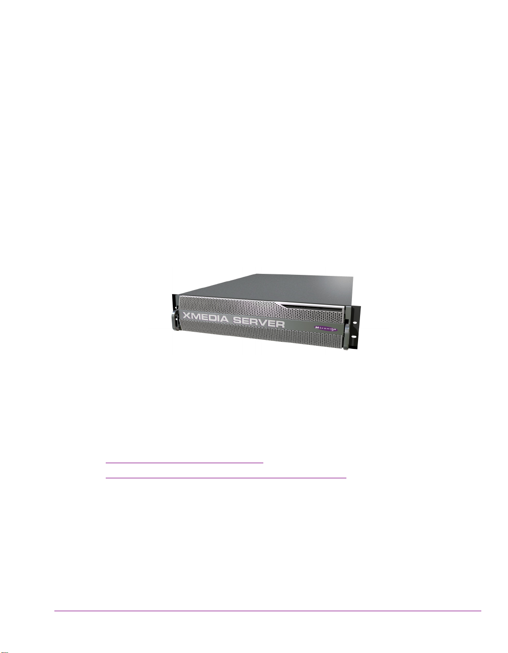
The Xmedia Server (XMS) is the central graphical asset management server for Vertigo
Suite channel branding and playout systems. The Xmedia Server allows all branding assets
to be ingested once, centrally archived, and automatically moved to the desired graphics
device using rule-based publishing.
Figure 1-1. Xmedia Server - a central graphical asset management server
The main purpose of this configuration guide is to provide practical reference and
procedural information on how to use the Xmedia Server Control Panel application to
configure the Xmedia Server.
The following sections of this chapter provide general information about the Xmedia Server
and its optional features:
About the Xmedia Server” on page 1-2
• “
• “Xmedia Server’s standard and option features” on page 1-3
The next couple of chapters provide specific information about the Xmedia Server’s
hardware, software, and network integration. Further chapters provide instructions for how
to configure the Xmedia Server using the Xmedia Server Control Panel.
XMS Configuration Guide 1-1
Page 25

Introduction
About the Xmedia Server
The Xmedia Server (XMS) is the central graphical asset management server for Vertigo
Suite channel branding and playout systems. Assets only need to be ingested once for them
to be centrally archived on the Xmedia Server. These assets are then made available to all
of the Vertigo Suite applications on the network, which allow you to create a wide range of
graphics, including advanced, data-driven broadcast applications that link on-air graphics
elements to live data feeds. The resulting graphic pages and their assets can then be
automatically published to a range of graphics playout devices, including Imagestore,
Intuition XG, and Vertigo XG devices.
The Xmedia Server offers benefits to larger broadcast systems that have multiple channels
by sharing assets between channels without having to duplicate the assets. It also allows
for a more dynamic handling of content and a more natural workflow because media
creation, asset management, and asset distribution are conveniently linked by a common
environment.
Besides its main use as a central asset repository and asset management/distribution
system, the Xmedia Server integrates and supports the Vertigo Suite applications and other
playout devices. The following list identifies other ways in which the Xmedia Server is used
to support graphics creation and playout activities:
• Asset propagation: The Xmedia Server can be used in a hub and spoke distribution
model in which assets can be created and propagated from a central hub to various
spoke servers.
• Server replication: Two Xmedia Servers can be configured to offer full redundancy for
near instant failover with no interruption in services, including on-air playout.
• Newsroom integration: The Xmedia Server can provide graphics assets to newsroom
environments using the MOS protocol to integrate with the newsroom control system.
• User rights management: Using the Xmedia Server’s user rights management
system, system administrators and workflow managers can restrict access to some of
the system’s functionality and/or asset categories on a per-user basis.
• License management: The Xmedia Server stores and manages the software licenses
that are required to operate each of the Vertigo Suite applications.
• Work Order Workflow: The Xmedia Server provides an optional work order workflow
module that fully integrates into the Vertigo Suite. The work order workflow is used for
requesting, completing, tracking and approving graphics work orders.
1-2 XMS Configuration Guide
Page 26

Xmedia Server’s standard and option features
The Xmedia Server is a 2RU rackmount server with 2TB of RAID-1 storage and is factory
configured to run Windows Server 2003 as its operating system. Additional software
applications and services that are factory installed include:
ICROSOFT SQL SERVER 2008: The Xmedia Server uses a Microsoft SQL Server
• M
database to store asset details, categories, work order processing data, publish
processing data, and other relational information and data. See page 5-1
information.
MEDIA SERVER CONTROL PANEL: The Xmedia Server Control Panel is the user interface
• X
for configuring and controlling the Xmedia Server. See page 3-14
ERTIGOXMEDIA DATA SERVER: The Data Server is a service application that manages
• V
data coming from various feeds, provides live updates of data values when requested and
distributes the data out to the appropriate recipients. See page 3-5 for more information.
• File Ingest Server: The File Ingest Server is a service responsible for automatically
ingesting media into the Xmedia Server from a user-created ingest folder. The File Ingest
Server is also responsible for issuing media conversion requests to the Transcode
Server, which is the service responsible for transcoding media from one format to another.
See page 3-13
In addition to the Xmedia Server unit, the following options are also offered to enhance the
capabilities of the Xmedia Server:
Work Order Management Option” on page 1-3
• “
• “Xplorer - Media Asset Management application” on page 1-3
for more information.
for more information.
for more
Introduction
Work Order Management Option
The Xmedia Server provides an optional work order workflow module (VX-WOM) that fully
integrates into the Vertigo Suite. The work order workflow is used for requesting,
completing, tracking and approving graphics work orders. See “
configuration” on page 10-1 for more information on how to use the Xmedia Server Control
Panel to create and configure the work order workflow module.
Work Order workflow
Xplorer - Media Asset Management application
The Vertigo Suite features the XPLORER application (VX-Xplorer), which is a graphical
content management system for viewing and managing the asset and file contents of the
Xmedia Server and the devices to which the XMS has published assets. See the X
SER MANUAL for more information.
U
XMS Configuration Guide 1-3
PLORER
Page 27

Introduction
1-4 XMS Configuration Guide
Page 28
2 XMS HARDWARE OVERVIEW
CAUTION
WARNING
°
Physically, the Xmedia Server is a 2RU rackmount server that incorporates redundant fans,
power, and ethernet ports, with 2 TB of RAID-1 storage. The Xmedia Server features easy
frontal access to the storage drives, and a control panel featuring LEDs and buttons for
system monitoring and operation. The rear panel also provides convenient access to two
power supply modules, seven PCI expansion slots (video, audio, and graphics cards), and
various I/O ports (USB, COM1, VGA, Ethernet...etc).
The following sections provide additional details regarding the Xmedia Server’s hardware:
Front panel components, LEDs and buttons” on page 2-2
• “
• “Back panel components and connectors” on page 2-4
• “Mounting the Xmedia Server chassis in a rack” on page 2-5
Xmedia Server devices should only be installed by trained personnel in a restricted access
locations only. All health and safety regulations and precautions must be observed.
Chassis F
Power consumption 700W (1 + 1) Redundant AC-DC power supply.
Temperature Ambient temperature: 35 C
To reduce the risk of electric shock, disconnect all power sources before servicing
Xmedia Server devices.
XMS Configuration Guide 2-1
ORM: 2U rackmount chassis
H
EIGHT: 3.5” (89mm)
W
IDTH: 17.2” (437mm)
D
EPTH: 25.5” (648mm)
Maximum draw is a total of 700W.
Note that the device’s electrical ratings are located on the
plug-in power supply modules.
Note: This shall be the maximum internal temperature within
the rack in which the Xmedia Server unit is installed.
Page 29
XMS hardware overview
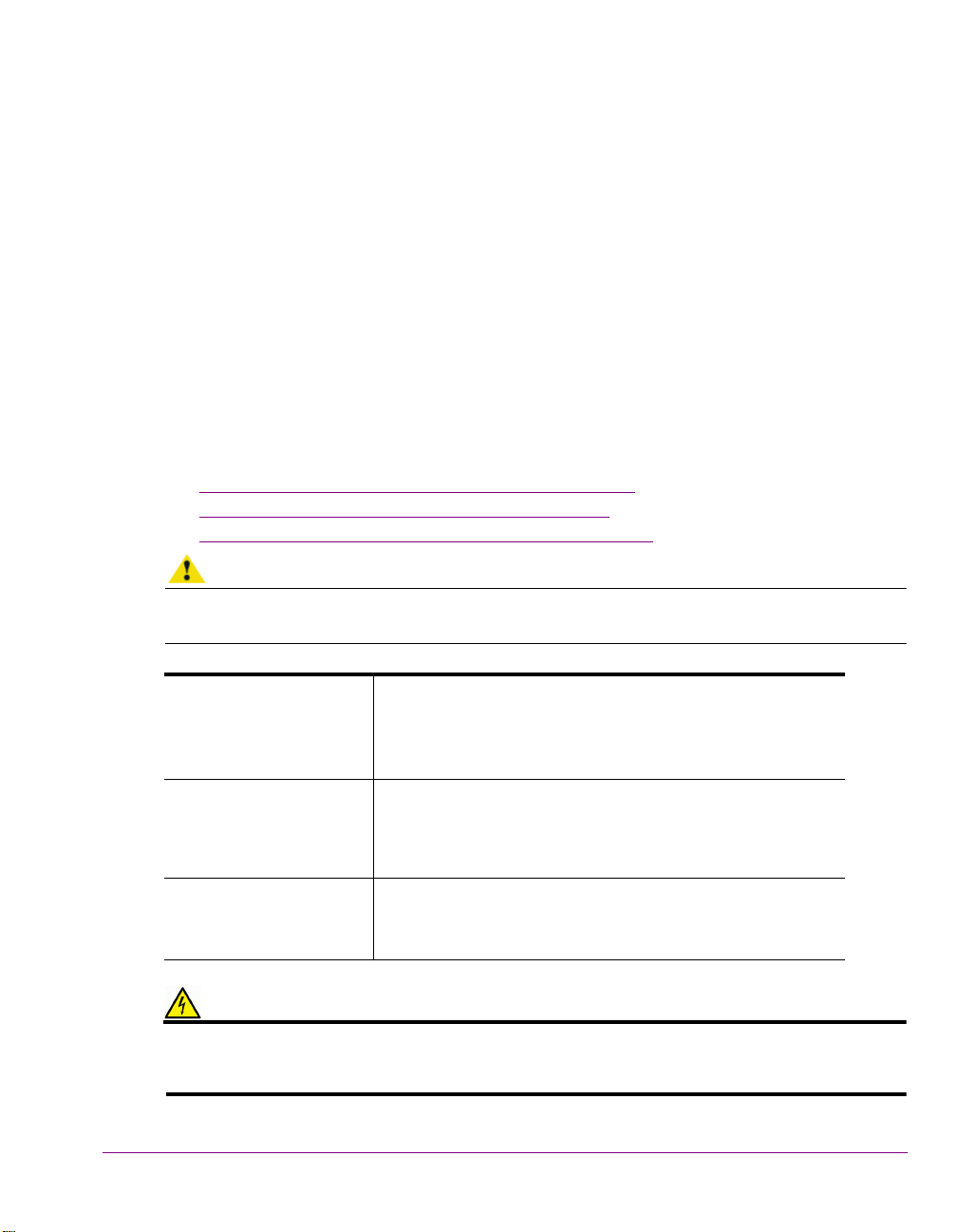
Floppy drive DVD-ROMFront Port Panel Control Panel
(LEDs & buttons)
RAID
Drives
Front panel components, LEDs and buttons
Figure 2-1 demonstrates that the Xmedia Server’s front panel provides easy access to the
SATA drives, a floppy drive, DVD-ROM, a front port panel (USB & serial) and a control panel
featuring LEDs and buttons for system monitoring and operation.
Figure 2-1. The Xmedia Server’s front panel components
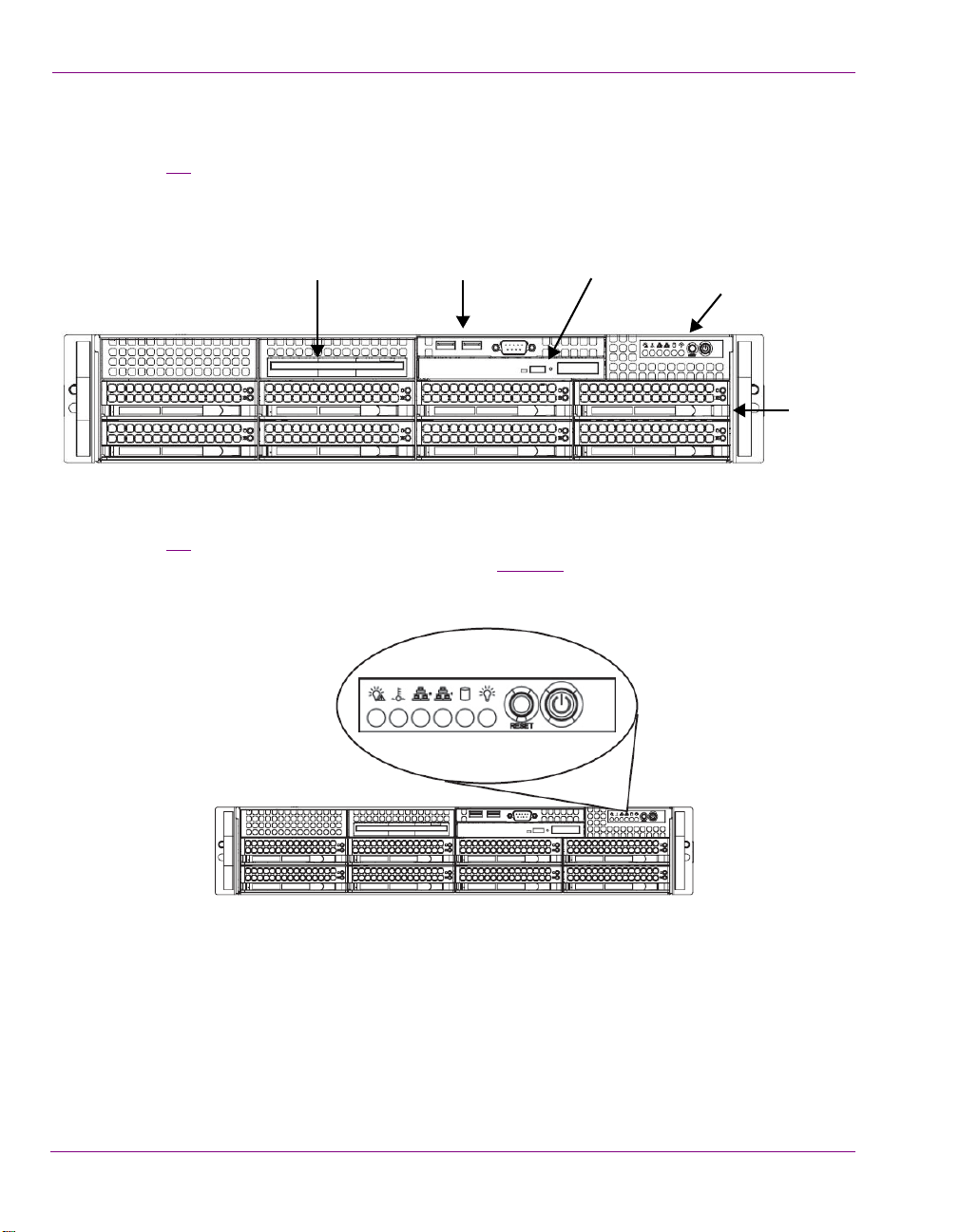
Figure 2-2
chassis has six LEDs and two buttons. The table on page 2-3 describes the function of each
LED and button, as well any corrective action you may need to take.
demonstrates that the control panel located on the front of the Xmedia Server
Figure 2-2. Xmedia Server chassis control panel LEDs and buttons
2-2 XMS Configuration Guide
Page 30
XMS hardware overview
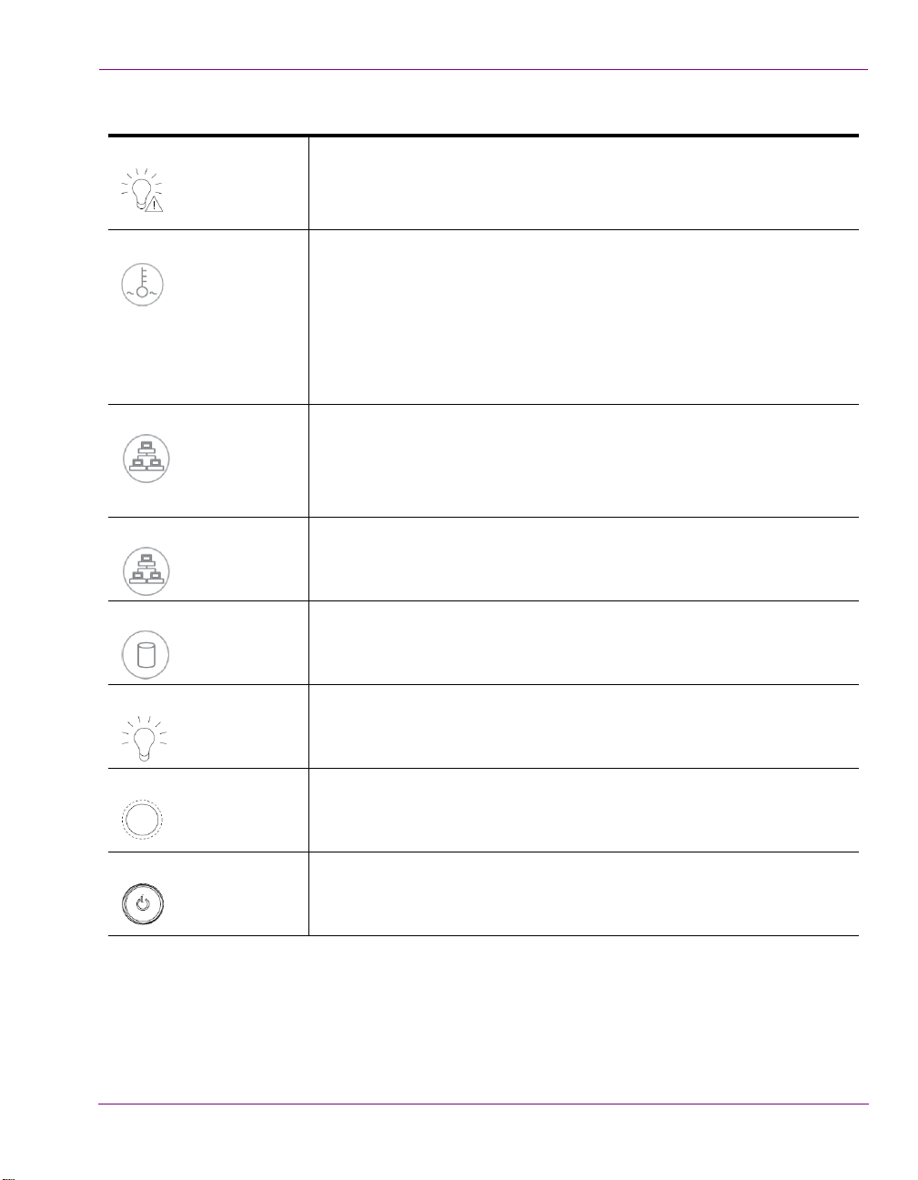
POWER FAIL Indicates a power supply module has failed. This should be accompanied
by an audible alarm. A backup power supply module will take the load and
keep the system running, but the failed module will need to be replaced.
This LED should be off when the system is operating normally.
VERHEAT / FAN FAIL When this flashes, it indicates a fan failure. When it is constantly
O
illuminated (solid on), it indicates an overheat condition, which may be
caused by cables obstructing the airflow in the system or the ambient room
temperature being too warm. Check the routing of cables and make sure
that all fans are present and operating normally. You should also check to
make sure that the chassis covers are installed properly. Finally, verify that
the heatsinks are installed properly. This LED will remain flashing or on as
long as the above mentioned conditions exist.
NIC2 A flashing NIC2 LED indicates network activity on LAN2.
NIC1 A flashing NIC1 LED indicates network activity on LAN2.
HDD Indicates IDE channel activity.
OWER (LED) Indicates that power is being supplied to the system’s power supply units.
P
This LED should normally be illuminated when the system is in operation.
R
ESET (BUTTON) The Reset button reboots the system.
OWER (BUTTON) This is the main power button, which is used to apply or turn off the main
P
system power. Turning off this button removes the main power, but keeps
standby power supplied to the system.
XMS Configuration Guide 2-3
Page 31

XMS hardware overview
NOTE
Power Supplies PCI Expansion Slots (not used)
I/O Ports
EthernetUSB
Mouse
connector
Keyboard
connector
Parallel port
(not used)
VGARS-232 Serial Port
(not used)
Back panel components and connectors
Figure 2-3 demonstrates that the rear panel of the Xmedia Server provides convenient
access to two power supply modules, seven PCI expansion slots (video, audio, and
graphics cards), and various I/O port connectors (USB, COM1, VGA, Ethernet...etc). When
using the Xmedia Server in a replication setup, you will insert the license dongle in one of
the USB ports (see page 6-8
).
Figure 2-3. The Xmedia Server’s rear panel components and connectors
The device’s electrical ratings are located on the plug-in power supply modules.
2-4 XMS Configuration Guide
Page 32

XMS hardware overview
CAUTION
Inner Rail Extensions
Inner Rails
Mounting the Xmedia Server chassis in a rack
Included in the shipping package is a rack mounting kit, which contains the rails, screws and
washers required to mount the Xmedia Server chassis into an equipment rack.
Note that the rails are designed to fit in racks with a depth of 26” to 33.5”. Due to the heavy
weigh of the unit, the rack in which the Xmedia Server unit will be installed should be
anchored to the building’s structure.
Xmedia Server devices are intended to be installed in a restricted access location by
qualified personnel. All health and safety regulations and precautions must be observed.
Included in the shipping package are a pair of rail assemblies. Each rail assembly consists
of two sections: an inner fixed chassis rail that secures directly to the server chassis and an
outer fixed rack rail that secures directly to the rack itself.
Figure 2-4
rails and inner rail extensions. The inner rails are pre-attached to the chassis, while the
inner rail extensions must be installed manually to the chassis.
demonstrates that the inner rail assemblies are composed of two sections: inner
Figure 2-4. The Enterprise Server’s inner rail assemblies
Once the inner rails are attached to the chassis, you must assemble and install the outer
rails to the rack. Once both the inner and outer rail assemblies are properly installed, you
can mount the Enterprise Server’s chassis into the rack by sliding the inner rails into the
outer rails.
Both chassis rails have a locking tab, which serves to lock the server in place when installed
and pushed fully in the rack, as well as preventing the server from coming completely out
when it is fully extended from the rack.
XMS Configuration Guide 2-5
Page 33

XMS hardware overview
A
B
To install chassis rails and mount the Xmedia Server’s chassis into an equipment rack:
1. Remove the Xmedia Server’s faceplate by pulling the faceplate’s handles away from
the chassis.
2. Install the inner rail extensions to the server’s chassis.
a. Place the inner rail extensions on the side of the chassis aligning the hooks of the
chassis with the rail extension holes. Be sure that the extension faces “outward”
just like the pre-attached inner rail.
b. Slide the extension toward the front of the chassis.
c. Secure the chassis with two screws as shown in figure 2-5
d. Repeat steps 2A - 2C for the other inner rail extension.
.
Figure 2-5. Installing the inner rail extensions
3. Install the outer rails to the rack (figure 2-6
a. Attach the shorter outer bracket to the outside of the longer rail. You must align the
pins with the slides. Both bracket ends must face the same direction.
b. Adjust the short and long brackets to the proper distance so that the rail fits snugly
with the rack.
c. Secure the longer bracket to the front of the outer rail with two screws.
d. Secure the shorter outer bracket to the rear side of the outer rail with three screws.
e. Repeat steps 3A - 3D for the remaining outer rail.
Figure 2-6. Installing the outer chassis rails to the equipment rack
2-6 XMS Configuration Guide
).
Page 34

XMS hardware overview
CAUTION
CAUTION
NOTE
4. Mount the Xmedia Server chassis into the rack (figure 2-7).
a. Align the inner rails on the chassis with the front of the outer rails on the rack.
b. Slide the inner rails into the outer rails, keeping the pressure even on both sides
(it may be necessary to depress the locking tabs when inserting). When the server
has been pushed completely into the rack, you should hear the locking tabs click
into the locked position.
The chassis may not slide into the rack smoothly or easily when installed for the
first time. Adjustments to the slide assemblies might be necessary to achieve a
smooth insertion.
c. (Optional) Insert and tighten the thumbscrews that hold the front of the chassis to
the rack.
Due to the heavy weight of the Xmedia Server, ensure that the rack is securely anchored onto
a unmovable surface or structure before installing the chassis into the rack.
Figure 2-7. Mounting the Enterprise Server’s chassis into a rack
Slide/rail mounted equipment is not to be used as a shelf or a workspace.
To completely remove the chassis from the rack, you must release the locking tabs on both
sides of the chassis.
5. Re-attach the faceplate by aligning and pushing the faceplate towards the Xmedia
Server’s chassis.
XMS Configuration Guide 2-7
Page 35

XMS hardware overview
2-8 XMS Configuration Guide
Page 36

3 XMS NETWORK INTEGRATION AND SERVICE
APPLICATIONS
It is recommended that the Xmedia Server be installed on a dedicated LAN, using the
existing security infrastructure. A qualified system administrator should verify that the setup
follows the organization’s security standards. Specific recommendations regarding proper
virus strategies, that won’t compromise performance are provided in this chapter.
As the centralized server for the Vertigo Suite of products, you can connect to the Xmedia
Server from any client PC on the network. All of connections used by the Vertigo Suite
applications are over TCP and UDP.
The following sections provide guidelines for integrating the Xmedia Server into your
network and an overview of the Data Server service, File Ingest Server and the Xmedia
Server Control Panel interface:
Xmedia Server virus protection guidelines” on page 3-2
• “
• “Xmedia Server network ports” on page 3-4
• “VertigoXmedia Data Server service” on page 3-5
• “File Ingest Server and Transcode Server” on page 3-13
• “Xmedia Server Control Panel - XmediaServer Properties Window” on page 3-14
XMS Configuration Guide 3-1
Page 37

XMS network integration and service applications
Switch
Internet
Network
Restricted
XStudio
Xmedia Server virus protection guidelines
Proper network setup and anti-virus software are key components of any virus protection
strategy. As such, we highly recommend that you adhere to specific rules outlined in this
section to avoid adversely affecting your production equipment’s on-air performance. Our
virus protection strategy, therefore relies on anti-virus software protection combined with
the following:
• Network Setup and Configuration
for maximum protection against infection.
• Standard Anti-Virus Protection
applications not directly used for putting material on-air.
• Institution of Policies
infected files into the system.
– Policies that all users must follow in order to avoid introducing
Network Setup and Configuration
Ideally, the Xmedia Server and other non-critical components should be running anti-virus
software, while the Vertigo XGs reside on a separate network. In such a case, the
Vertigo XGs would not be running anti-virus software, leaving them potentially vulnerable.
Therefore, provide proper protection and minimizing potential performance issues, it is
recommended that restricted access be available by means of switch (see figure 3-1
also recommended that all other Xmedia equipment would be kept on a separate network
isolated from other machines in the facility.
– A best case scenario for configuring your network
– Standard anti-virus practices for machines and
). It is
Figure 3-1. Recommended network configuration to provide virus protection
3-2 XMS Configuration Guide
Page 38

Standard Anti-Virus Protection
While critical for the on-air production process, many of the Vertigo Suite products do not
put material directly on air. We therefore recommend that these products be configured with
the same high level of anti-virus protection used for other machines on the broadcaster’s
network.
The following Vertigo Suite products should be configured with the highest level of anti-virus
protection:
• Xmedia Server
• Data Server
•Xstudio
• Xbuilder
Institution of Policies
While the guidelines outlined in the previous sections are critical to your broadcast
network’s protection from infection, end users must accept some responsibility. We
therefore recommend that your IT department enforce the following policies:
• Any machine that will be attached to the same network as the Xmedia Server must
undergo a complete system scan.
• Any floppy, zip or other external media to be copied to or run on the Xmedia Server
must undergo a complete scan.
• Material to be used in 24/7 operation should not be copied to the Xmedia Server.
Instead, it should be transferred only during maintenance periods.
• Do not download Internet files directly onto the Xmedia Server.
XMS network integration and service applications
XMS Configuration Guide 3-3
Page 39

XMS network integration and service applications
Xmedia Server network ports
Users can connect to the Xmedia Server from any client PC on their network. All of
connections used by the Vertigo Suite applications are over TCP and UDP, using the
configurable range of ports listed below:
Description Port # Protocol
Client application connection (Primary connection) 14050 TCP
Client application connection (Back channel) 14051 TCP
Publish connection (Back channel) 14052 TCP
DataServer primary connection 10460 TCP
XPublish Agent publishing port 15000 TCP
MOS low port 10540 TCP
MOS high port 10541 TCP
Discovery port 15098 UDP
Discovery port 15099 UDP
Device connections (client apps to device) 4000 TCP
3-4 XMS Configuration Guide
Page 40

XMS network integration and service applications
Xstudio’s Data Manager
Data Source
Data Server
Xmedia Server
Schemas
Data Source updates
VertigoXmedia Data Server service
The Data Server is a service that runs in the background on the Xmedia Server and is
responsible for managing data coming from various feeds by providing live updates of data
values when requested, and distributing the data to the appropriate recipients (figure 3-2).
Figure 3-2. The Data Server manages and distributes data from various data sources
ATA SERVER CONTROL PANEL (VertigoXmedia Data Server Option window) is the user
The D
interface that is used to configure and control the Data Server service (figure 3-3). You can
open the Data Server Control Panel by selecting:
TART > SETTINGS > CONTROL PANEL >VERTIGOXMEDIA DATA SERVER.
S
Figure 3-3. The Data Server Control Panel
XMS Configuration Guide 3-5
Page 41

XMS network integration and service applications
The Data Server Control Panel features three (3) tabbed pages that contain parameters for
configuring the connection, metadata, and logging options, as well as stopping and starting
the Data Server service.
The upper portion of the Data Server Control Panel’s G
Server’s software version, the directory path where the Data Server’s executable file is
located, and the working directory path.
The following sections provide information and instructions for how to use the Data Server
Control Panel to configure and manage the Data Server service.
Setting the Data Server’s connection parameters” on page 3-7
• “
• “Logging Data Server events” on page 3-9
• “Controlling the Data Server service” on page 3-11
ENERAL page identifies the Data
3-6 XMS Configuration Guide
Page 42

XMS network integration and service applications
Setting the Data Server’s connection parameters
The Data Server Control Panel’s GENERAL page features parameters that allow the Data
Server to connect and communicate with the Xmedia Server.
The TCP/IP section on the GENERAL page allows you to set the communication port number
at which the Data Server listens for incoming data. Figure 3-4
Server Control Panel’s L
ISTENING PORT field must always be set to 14060.
Figure 3-4. Setting the Data Server’s communication port
demonstrates that the Data
The following table describes the parameters in the M
ETADATA section on the GENERAL
page, which determine the Data Server’s settings for connecting and communicating with
the Xmedia Server(s).
HOST / PORT These settings are used to identify the primary Xmedia Server that the Data
XMS
Server will connect to.
• Specify the IP address or machine name of the Xmedia Server that
hosts the XMS Service.
• Specify the communication port that allows a service to connect to an
Xmedia Server. Typically, the port number is 14050.
ACKUP XMS HOST /
B
PORT
When operating within a server replication setup, these settings are used to
identify the secondary Xmedia Server that the Data Server will connect to if
the primary XMS server fails to respond.
• Specify the IP address or machine name of the secondary Xmedia
Server in the B
ACKUP HOST field.
• Specify the communication port of the secondary Xmedia Server in the
ACKUP PORT field. Typically, the port number is 14050.
B
M
ETADATA DIRECTORY Specify the directory path to the METADATA folder that contains all of the xml
data that the data server needs to retrieve data. The folder is usually stored
in C:\Program Files\VertigoXmedia\Apps\.
This folder is primarily used when the data server can no longer connect to
the XMS.
XMS Configuration Guide 3-7
Page 43

XMS network integration and service applications
SILENCE SERVER ON MAIN
XMS
CONNECTION
This setting has been primarily replaced by the CONTROL THE DATASERVER
setting on the Xmedia Server Control Panel’s S
page 16-5
).
ERVICE CONTROL page (see
When enabled, this setting causes the Data Server service to cease if the
Xmedia Server connection is lost. In a replication setup, this condition
forces a failover to the secondary Xmedia Server.
U
SE LAZY LOADING When enabled, the Data Server does not parse the schemas until they are
requested.
3-8 XMS Configuration Guide
Page 44

Logging Data Server events
NOTE
The Data Server Panel’s LOGGING page (figure 3-5) allows you to set parameters to create
a logging criteria that records the status of Data Server events. The resulting logging
information is recorded and saved to a DataServer*.log file, which can be opened a
basic text editor to determine whether the Data Server is being used correctly or help
diagnose error conditions.
Be aware that logging may adversely affect the product’s performance, especially on air
performance. Therefore, we recommend enabling logging only when you are troubleshooting.
XMS network integration and service applications
Figure 3-5. Data Server Panel’s Logging page
The Data Server’s Logging Levels and Debug Categories settings allow you to specify the
type and categories of events that you want to be recorded in the Xmedia Server log files.
Log Level
This sets the default log level used by all logging categories except those that have been
checked in the Debug Categories list. The choices are:
• Error - Only log errors and essential operations.
• Warn - Log unsuccessful operations that may indicate a problem (in addition to all
messages logged at the Error level).
• Info - (Default) Log important events that occur during normal conditions (in addition to
all messages logged at the Warn level).
It is recommended to set the Log Level to Info in order to provide enough information in
the logs to diagnose common problems without affecting performance.
XMS Configuration Guide 3-9
Page 45

XMS network integration and service applications
Debug Categories
Select the types of debug logging (categories) that you would like to record in the Data
Server log file:
ENERAL - General logging that does not fit under any other category.
• G
ATABASE - Database connections
• D
CP - Network activities
• T
• HTTP - Activities related to the retrieval of HTTP protocol (Internet) activities
ETADATA - Data source parsing
• M
ILE - File handling
• F
NIT - Startup and process initialization
• I
OCIALMEDIA - Activities related to the retrieval of social media data
• S
The SELECT NONE button de-selects all of the Debug categories at once.
Log Destinations
All log files related to Vertigo Suite products are centrally archived in the Xmedia Server
OG TO CONSOLE: Currently not available for external use. The events are written to a
•L
console for Grass Valley personnel to use for testing and debugging tasks.
ILE SIZE - Sets the maximum memory size for each log file created per run. The default
• F
value is 6 MB.
ILE COUNT - Specifies the maximum number of DataServer*.log files that will be
• F
stored. A large enough number should be chosen to store over a day's worth of logs.
This way if a problem happens the relevant log files will be available. Once the
maximum number of files is reached, the oldest log file will be replaced by a new one.
The default value is 20.
To access and view the contents of the most recent or archived DataServer*.log files:
1. Open Windows Explorer and navigate to the Vertigo Suite’s log folder:
C:\Documents and Settings\All Users\Application Data\VertigoXmedia\Logs
2. Click on the NAME column’s heading to sort the files.
3. Double click the DataServer*.log file that you want to display and it opens in a text
editor (i.e. Notepad).
3-10 XMS Configuration Guide
Page 46

XMS network integration and service applications
Controlling the Data Server service
By default, the Data Server service is set to automatically start when its host machine
(i.e. Xmedia Server) is started. You can then use the controls on the Data Server Panel’s
ERVICE page to stop and start the service (figure 3-6). The service’s current state (started
S
or stopped) is always reported on this page as well.
Figure 3-6. Manual controls for starting and stopping the Data Server service
In a replication environment, we recommend that authority to start and stop the Data Server
service be given to the Xmedia Server by enabling the C
on the Xmedia Server Control Panel (figure 3-7). The CONTROL THE DATASERVER setting
ties the control of the Data Server service to the starting and stopping of the XMS service.
Enabling this setting ensures the Data Server remains paired with the Xmedia Server at all
times in the replication environment (see page 16-5
Figure 3-7. Configure the Xmedia Server Control Panel to control the Data Server service
XMS Configuration Guide 3-11
ONTROL THE DATASERVER setting
for more information).
Page 47

XMS network integration and service applications
The figures below demonstrate that once the CONTROL THE DATASERVER setting is enabled,
the following changes are applied to the Data Server panel’s GENERAL and SERVICE pages:
General Page
• The upper portion of the General page’s software identification banner reads:
C
ONTROLLED BY THE XMEDIA SERVER.
Service Page
• The manual start and stop controls become disabled
• The upper panel displays the following message: X
CONTROL THE DATASERVER
•The SERVICE STATE message reports that the service is DISABLED, rather than START
AUTOMATICALLY
MEDIASERVER IS CONFIGURED TO
3-12 XMS Configuration Guide
Page 48

XMS network integration and service applications
File Ingest Server and Transcode Server
The Vertigo File Ingest Server is a service responsible for automatically ingesting media into
the Xmedia Server from a user-created ingest folder. The File Ingest Server is also
responsible for issuing media conversion requests to the Transcode Server, which is the
service responsible for transcoding media from one format to another.
File Ingest Server can be configured to watch one or more folders by defining one or more
instances of the ingest service in the configuration file. Each instance defines the set of
rules that are mapped to each ingest folder being watched.
Information and instructions for using the File Ingest Server and Transcode Server are
provided in “
Ingesting media files using the File Ingest Server” on page 21-1.
Figure 3-8. File Ingest Server Control Panel
XMS Configuration Guide 3-13
Page 49

XMS network integration and service applications
NOTE
Xmedia Server Control Panel - XmediaServer Properties Window
The user interface for configuring and controlling the Xmedia Server is the XMEDIA SERVER
ONTROL PANEL (figure 3-9). The Xmedia Server Control Panel features fifteen (15) tabbed
C
pages that contain parameters and settings related to the configuration and functioning of
the Xmedia Server.
Figure 3-9. The Xmedia Server Control Panel
Although the title bar of this window displays XMEDIASERVER PROPERTIES, it is most
commonly referred to as the XMEDIA SERVER CONTROL PANEL.
Once the Xmedia Server has been installed, you can open the Xmedia Server Control Panel
window by selecting: S
Behind the Xmedia Server Control Panel’s user interface runs the XMS
The XMS service’s main responsibilities are to manage the Xmedia Server’s interaction with
the Vertigo Suite applications and to define the configuration settings for different Xmedia
system setups and uses.
3-14 XMS Configuration Guide
TART > SETTINGS > CONTROL PANEL > VERTIGOXMEDIA XMEDIA SERVER.
SERVICE application.
Page 50

XMS network integration and service applications
In most cases, the XMS Service is set to automatically launch when the Xmedia Server is
started and it runs in the background, regardless of whether or not any applications from
the Vertigo Suite have been opened. If the XMS service fails to start, the Xmedia Server
Control Panel’s S
(figure 3-10
ERVICE CONTROL page allows you to verify the status of the XMS Service
) and restart the service if necessary. See “Controlling the XMS service” on page
16-1 for more information.
Figure 3-10. The Service Control page displays the state of the XMS Service
XMS Configuration Guide 3-15
Page 51

XMS network integration and service applications
Xmedia Server Control Panel’s settings pages
The following table describes the Xmedia Server Control Panel’s fifteen (15) tabbed pages
that contain the parameters and settings that are used to configure the Xmedia Server to
interact with the Vertigo Suite applications and offer extended functionality.
Xmedia Server
Control Panel Tab
G
ENERAL The GENERAL tab displays the Xmedia Server Control Panel’s product
Description
information, as well as parameters for configuring the XMS’s communication
port and directories. This page also features the Authorization Manager
Configuration settings, which are used for enabling user rights management.
The XMS’s general configuration settings” on page 4-1 for more
See “
information about setting the parameters on the GENERAL page.
DATABASE The DATABASE tab allows you to select and configure the Xmedia Server’s
database settings, as well as how to take a backup of the SQL Server database.
See “Verifying the XMS’s database settings” on page 5-1 for more information
about setting the parameters on the DATABASE page.
REPLICATION The REPLICATION tab allows you to configure the current Xmedia Server to
participate in a replication setup, which offers full redundancy for near instant
failover with no interruption in services including on-air playout.
Replication of the XMS Server’s database” on page 6-1 for more
See “
information about setting the parameters on the REPLICATION page.
MOS The MOS tab allows you to configure the Xmedia Server to integrate with a
newsroom control system. The Xmedia Server can then provide graphics assets
to newsroom environments using the MOS protocol.
See “MOS Server configuration and monitoring” on page 7-1 for more
information about setting the parameters on the MOS page.
ICENSING The LICENSING tab allows you to view, add, and remove the software licenses
L
that are required to operate each of the Vertigo Suite applications.
See “
License management” on page 8-1 for more information about setting the
parameters on the L
ICENSING page.
LOGGING The LOGGING tab allows you to set parameters for creating and viewing a log file
that records the status of events while the Xmedia Server is operating.
Logging Xmedia Server events” on page 9-1 for more information about
See “
setting the parameters on the L
OGGING page.
3-16 XMS Configuration Guide
Page 52

XMS network integration and service applications
SERVICE CONTROL The SERVICE CONTROL tab displays the current state of the XMS Service. It also
allows you to manually stop and start the XMS service, and set Service Options
for automatically restarting the XMS Service, linking the XMS to the DataServer
and/or enabling the REST Interface functionality.
Controlling the XMS service” on page 16-1 for more information about
See “
setting the parameters on the S
ERVICE CONTROL page.
RUNTIME STATIST ICS The RUNTIME STATISTICS tab displays a real-time tally of the content of the
Xmedia Server’s database.
Displaying XMS runtime statistics” on page 17-1 for more information about
See “
setting the parameters on the R
UNTIME STATIST ICS page.
PROPAGATION The PROPAGATION tab allows you to create a hub and spoke asset distribution
model in which assets can be created and propagated from a central hub to
various spoke servers.
See “Propagating assets to other Xmedia Servers” on page 18-1
for more
information about setting the parameters on the PROPAGATION page.
PUBLISHING The PUBLISHING tab displays a real-time view of the status of media assets that
are currently being published. This view allows you to easily clear/cancel some
or all of the pending publish requests. This tab also allows you to enable the
insta-publish device option.
Setting and monitoring the XMS publishing activities” on page 19-1 for
See “
more information about setting the parameters on the PUBLISHING page.
WORKFLOW The WORKFLOW tab allows you to create a work order workflow that is used for
requesting, completing, tracking and approving graphics work orders.
Work Order workflow configuration” on page 10-1 for more information
See “
about setting the parameters on the WORKFLOW page.
SYSTEM PARAMETERS The SYSTEM PARAMETERS page allows you to set the rate at which media objects
are ingesting into the Xmedia Server, at what time expired published and
archived assets will be purged, and the system’s field rate.
Setting the XMS system parameters” on page 11-1 for more information
See “
about setting the parameters on the SYSTEM PARAMETERS page.
OXSOX The OXSOX tab allows you to configure the Xmedia Server to communicate with
the ImageStore Media Manager (IMM) or/and Xplorer applications, which both
use the Oxsox protocol.
OxSox connection settings” on page 12-1 for more information about
See “
setting the parameters on the O
XSOX page.
XMS Configuration Guide 3-17
Page 53

XMS network integration and service applications
AUTOMATION The Xmedia Server Control Panel’s AUTOMATION page configures the Xmedia
Server to communicate with a specific automation system for the purposes of
publishing to devices based on the automation system’s schedule.
The XMS automation parameters for scheduled-based publishing” on page
See “
13-1 for more information about setting the parameters on the AUTOMATION
page.
*** Note ***
Although the Automation page still exists on the Xmedia Serve Control Panel,
the functionality of scheduled-based publishing has been deprecated.
XFTP Although the XFTP page still exists on the Xmedia Serve Control Panel, the
functionality of importing files using a FTP server running locally on the Xmedia
Server been deprecated.
RAPHICS BANK The GRAPHICS BANK page contains settings that are required to display and
G
activate AP GRAPHICS BANK components in Xnews and the Vertigo Suite’s Work
Orders windows.
Enabling AP Graphics Bank integration” on page 15-1 for more information
See “
about setting the parameters on the G
RAPHICS BANK page.
3-18 XMS Configuration Guide
Page 54

4 THE XMS’S GENERAL CONFIGURATION
SETTINGS
The GENERAL page on the Xmedia Server Control Panel (figure 4-1) allows you to view and
set some of the Xmedia Server’s basic configuration and connection settings. The GENERAL
page is divided into three (3) thematic areas and each is described in the following sections:
Viewing the Xmedia Server’s product information” on page 4-2
• “
• “Configuring the XMS’s network connection and directories” on page 4-3
• “Configuring the Authorization Manager” on page 4-4
Figure 4-1. The General tab on the Xmedia Server Control Panel
XMS Configuration Guide 4-1
Page 55

The XMS’s general configuration settings
Viewing the Xmedia Server’s product information
The Xmedia Server Control Panel’s GENERAL page provides a quick view of the Xmedia
Server’s product information (figure 4-2
of information regarding the Xmedia Server:
• Vers ion: Identifies the version and build number of the Vertigo Suite that is currently
installed and running on the Xmedia Server.
• Executable is: Identifies the full directory path of where the Xmedia Server executable
file is located.
• Working directory: Identifies the full directory path of the VertigoXmedia Apps folder
that contains the Vertigo Suite’s .ini files, license files, some log files, and some MOSrelated XML files.
). This page displays the following three (3) pieces
Figure 4-2. Xmedia Server product information on the Xmedia Server Control Panel’s General page
4-2 XMS Configuration Guide
Page 56

The XMS’s general configuration settings
Configuring the XMS’s network connection and directories
The Xmedia Server Control Panel’s GENERAL page (figure 4-2) features two sections that
allow you to specify and view the Xmedia Server’s communication port and the full directory
paths where the XMS stores or retrieves information from. The following table provides
more details about each field in these sections:
TCP/IP Configuration Listen for incoming connections on port: The port number at which the
Xmedia Server (XMS) will listen. IP address is the local IP.
Directories Configuration Virtual database path: The full directory path to the Virtual Database
(VDB). The Virtual Database is a directory structure that contains all the
hard assets that the XMS stores.
Working folder: Identifies the full directory path of the VertigoXmedia
Apps folder that contains the Vertigo Suite’s .ini files, license files, some
log files, and some MOS-related XML files.
Filter directory: The full path to of the directory that contains filters such
a LEAD tools filters. Filters are used to convert data from one format to
another.
Figure 4-3. Xmedia Server connection and directories on the Xmedia Server Control Panel’s General page
XMS Configuration Guide 4-3
Page 57

The XMS’s general configuration settings
Configuring the Authorization Manager
The Vertigo Suite offers system administrators and workflow managers the possibility of
restricting access to some of the functionality on a per-user basis using the Xmedia Server
and the operations, tasks, and roles defined in Microsoft’s Authorization Manager (see
User rights management” on page 20-1 for more information).
“
Use of the Vertigo Suite’s User Rights Management is completely optional and it can be
configured, enabled, or disabled using the settings on the Xmedia Server Control Panel’s
ENERAL page (figure 4-4).
G
Authorization Manager
Configuration
Figure 4-4. The Authorization Manager portion of the Xmedia Server Control Panel’s General page
Enabled: If checked, it will ensure that next time the XMS runs, it will
create a shared directory called AzMan in the working directory.
Furthermore, it enables the authorization manager in the Xmedia Server.
Policy store URL: Specifies the path of the policy store, which is a file that
helps the AzMan coordinate user rights management. The file is stored in
either the active directory or on disk as an XML file.
Application name: The name of the object that contains rights for the user
in the application.
4-4 XMS Configuration Guide
Page 58

5 VERIFYING THE XMS’S DATABASE
NOTE
SETTINGS
The Xmedia Server uses a Microsoft SQL Server database to store asset details,
categories, work order processing data, publish processing data, and other relational
information and data.
The following sections describe how to use the Xmedia Server Control Panel’s DATABASE
page to verify the Xmedia Server’s database settings, how to take a backup of the SQL
Server database, as well as monitor the XMS Search connectivity to Solr:
Verifying the SQL Server database settings” on page 5-2
• “
• “Making a backup of the SQL Server database” on page 5-4
• “Monitoring the XMS Search’s Solr connectivity and indexing” on page 5-5
The Xmedia Server’s database settings have been factory configured and/or commissioned
by qualified Grass Valley professionals. Although this chapter instructs users on how to
verify the Xmedia Server Control Panel’s database settings, we strongly discourage users
from making changes to database settings without the guidance of the our Technical
Support department (support@grassvalley.com).
XMS Configuration Guide 5-1
Page 59

Verifying the XMS’s database settings
Verifying the SQL Server database settings
The Vertigo Suite uses a Microsoft SQL Server database to store and manage asset details,
categories, work order processing data, publish processing data, and other relational
information and data. The following instructions describe how to verify the MS SQL SERVER
SETTINGS on the Xmedia Server Control Panel’s Database page (figure 5-1)
Figure 5-1. The MS SQL Server settings
To verify the MS SQL Server settings:
1. Select the D
2. Verify that MS SQL S
3. Click the T
The connection test validates the current MS SQL SETTINGS values. If the TEST
DATABASE CONNECTION pop-up window reports a successful connection (figure 5-2),
this indicates that all of the current settings are valid and you do not need to continue
the verification procedure.
If the T
the current MS SQL SERVER SETTINGS are invalid and you must continue with this
procedure to verify these settings.
ATABASE tab on the Xmedia Server Control Panel.
ERVER is displayed in the DATABASE TYPE field.
EST CONNECTION button to verify the connection to the database.
EST DATABASE CONNECTION pop-up window reports a failed connection (figure 5-2),
Figure 5-2. Testing the database connection is a quick way to verify the validity of the SQL Server settings
4. Verify that the S
ERVER NAME and the DATABASE NAME fields are accurate on the
Xmedia Server Control Panel’s Database settings page.
5-2 XMS Configuration Guide
Page 60

Verifying the XMS’s database settings
Server name
Database name
The server and database names can be obtained by opening the SQL SERVER
MANAGEMENT STUDIO.
a. Open the SQL S
M
ICROSOFT SQL SERVER 2008 R2>SQL SERVER MANAGEMENT STUDIO.
b. Click C
ONNECT in the CONNECT TO SERVER window.
ERVER MANAGEMENT STUDIO by selecting START > PROGRAMS>
c. In the Object Explorer panel of the Microsoft SQL Server Management Studio
window, expand the D
ATABASES folder to display the name of the database.
d. Verify that the server name and database name match those specified on the
Xmedia Server Control Panel’s Database settings page.
5. Verify that the U
SER NAME and PASSWORD provides a security measure to ensure that only the
The U
SER NAME and PASSWORD fields are accurate.
qualified user (i.e. the system administrator) has permission to connect, write, and read
to the database.
By default these fields are both set to sa. Contact your system administrator if the U
AME or PASSWORD appear to be different than the default.
N
6. Verify that C
ONNECTION POOLING is enabled and set to 10.
SER
When this setting is enabled, the value specified establishes the number of
connections in the connection pool. Having a connection pool helps the Xmedia Server
service its clients in a timely fashion. When this setting is disabled, it will not use a
connection pool to the database and it will have only a single connection.
7. Click the T
EST CONNECTION button to verify the validity of the settings and the
connection to the database.
EST DATABASE CONNECTION pop-up window again reports a failed connection,
If the T
contact our Technical Support department for assistance (support@grassvalley.com
XMS Configuration Guide 5-3
).
Page 61

Verifying the XMS’s database settings
Making a backup of the SQL Server database
The DATABASE BACKUP section of the Database page (figure 5-3) allows you to create or
update a backup of the Xmedia Server’s MS SQL Server database.
When the BACKUP DATABASE button is selected, the osql utility is executed and a backup file
(XmediaSuite.bak) is created/updated and saved within the root folder of the server’s
Virtual Database (as indicated by the directory path in the VIRTUAL DB ROOT DIRECTORY field).
Figure 5-3. Create or update a backup of the Xmedia Server’s MS SQL Database
5-4 XMS Configuration Guide
Page 62

Verifying the XMS’s database settings
Monitoring the XMS Search’s Solr connectivity and indexing
The XMS SEARCH component in Xplorer and the Vertigo Suite’s Work Orders management
system uses Solr, which a web-based solution by the Apache group that performs fast
search across a large amount of data.
The XMS S
4) features components for monitoring the connection status, as well as a buttons for
manually interacting with the Solr process.
Figure 5-4. XMS Search’s Solr connectivity status and manual indexing components
Solr connectivity
Each time the Xmedia Server is started, a connection to a new instance of the Solr process
is established. Stopping the Xmedia Server Service ends the instance of the Solr process.
When the Solr process is actively connected to the Xmedia Server, the status reads:
“Solr connection established!”
If the Xmedia Server service is not running or if for any other reason the connection to Solr
is not established, the status reads: “Solr is unavailable!”
To reconnect Solr, ensure that the Xmedia Server Service is running and/or troubleshoot
any network issues. Then click the REFRESH button to launch another connection attempt.
EARCH portion of the Xmedia Server Control Panel’s DATABASE page (figure 5-
Reindexing the database
Upon installing Vertigo Suite v5.0 (or later), the Xmedia Server performs an initial indexing
of the database and then performs daily indexes after all expired assets have been deleted
(see page 11-3).
Clicking the REINDEX button allows you to launch a manual indexing of the database at
anytime.
XMS Configuration Guide 5-5
Page 63

Verifying the XMS’s database settings
5-6 XMS Configuration Guide
Page 64

6 REPLICATION OF THE XMS SERVER’S
DATABASE
Replication enables full redundancy of an Xmedia Server that is available for near instant
failover with no interruption in services including on-air playout.
The Xmedia Server implements a simple technique of replicating all events that change the
database and/or virtual database (VDB). Two identically versioned Xmedia Servers
(Primary and Secondary) communicate with each other to ensure database replicas by
queuing all commands that alter the state of the database (and/or VBD) to disk. These
commands are then sequentially executed on the secondary server as if it were a normal
client with a few distinctions.
The primary server’s connection to the secondary server is distinct in that the secondary
server does not send normal replies to the primary server. Instead, it replies with simple
acknowledgements. Most data altering commands consist of user-invoked changes such
as Template saving, whereas other hidden changes, such as publish history and licensing
changes such as soft-key ingestion, are also replicated.
At all times both servers are running and the secondary server is ready to take control when
a failover condition arises at any time. Both servers contain identical licensing information
and each has their own dongle with matching customer IDs. Each server is responsible for
monitoring network conditions and each other’s availability.
The following sections further describe the conditions and behavior of the Xmedia Servers
replication. Instructions are also provided to guide you through the process of setting up and
enabling server replication.
Conditions that trigger a failover” on page 6-2
• “
• “MOS Enabled Replication” on page 6-3
• “Replication settings on the Xmedia Server Control Panel” on page 6-4
• “Setting up and enabling Xmedia Server replication” on page 6-6
XMS Configuration Guide 6-1
Page 65

Replication of the XMS Server’s database
Conditions that trigger a failover
The primary server makes an active TCP connection to the secondary on its main XMS port,
which is typically 14050. When this connection is dropped, there are two perspectives from
which to describe. Firstly, if the secondary server dropped the connection, then the primary
server immediately attempts to reconnect and periodically tries on defined intervals (in
seconds), while it remains running as usual. Secondly, if the primary server dropped the
connection, the secondary server slips into a temporary wait state awaiting the primary
server’s reconnection for a period of time in seconds. If the primary server has not
reconnected within the defined period, the secondary server assumes control and begins
accepting connections from clients.
A failover occurs when one or more of the following conditions are met:
• The primary Xmedia Server service is stopped.
• The primary server loses network connectivity.
• The primary Xmedia Server service involuntarily crashes.
• The primary server tells the secondary server to takeover for otherwise unknown
purposes, see the primary server’s log file.
• The primary server loses its connection with the SQL server database.
• The primary server is powered off.
The secondary server assumes control by accepting connections from clients only when the
primary server is inoperable. While the secondary server is accepting connections it queues
the data changing events to disk, exactly like the primary server does when operating
normally. While the secondary server is live, it periodically checks for primary server
availability by attempting to connect to it.
Once the primary server is back online, the secondary server unloads the queue to the
primary server, and when the queue is empty, the primary server resumes control and the
secondary server resumes its role. The primary server is operable whenever it is running
and the backlog queue from the secondary server is emptied.
6-2 XMS Configuration Guide
Page 66

MOS Enabled Replication
Xmonitor
XMS_1
Xmonitor
XMS_2
Virtual
IP Address
Local Area Network (LAN)
Static IP AddressStatic IP Address
Xmonitor
XMS_1
Xmonitor
XMS_2
Virtual
IP Address
Local Area Network (LAN)
Static IP AddressStatic IP Address
In MOS enabled environments,
the primary XMS adds the
Virtual IP address to the public
network adapter.
The two servers cannot concurrently
support the same Virtual IP address.
Therefore, when a failover occurs
on the primary server, the Xmonitor
service is responsible for removing
the Virtual IP address from the
network adapter of the primary server
and connecting the secondary server.
When MOS is enabled in the Xmedia Server Control Panel (see page 7-1), additional
replication requirements must be met. The Newsroom Control System (NCS), which
requires the Xmedia Server MOS presence, is configured to be aware of the Xmedia Server
using a single IP address, which is often referred to as the Virtual IP address.
Figure 6-1 demonstrates that in MOS enabled environments the primary XMS adds the
virtual IP address to the public network adapter. On failover, the primary server releases the
virtual IP and the secondary server adds the IP address to its public network adapter. Since
the two servers cannot concurrently support the same IP address, the Xmonitor service is
responsible for removing the Virtual IP address from the public network adapter of the
primary computer when the primary XMS tells it to, or when it suddenly stops or crashes. It
functions the same way on the secondary server as well. Without the Xmonitor service,
messages would appear on the network indicating an IP address conflict on the network.
Replication of the XMS Server’s database
Figure 6-1. A Virtual IP Address must be available for replication when MOS is enabled
The Xmonitor.exe is part of the standard install, but it is not automatically configured to
run as a permanent service. Therefore, as part of the replication setup you must manually
install and start the Xmonitor service. See “
on page 6-11 for instructions and further information regarding the Xmonitor service.
XMS Configuration Guide 6-3
Verify and/or install the Vertigo Xmonitor service”
Page 67

Replication of the XMS Server’s database
Replication settings on the Xmedia Server Control Panel
Replication is setup and enable using the Xmedia Server Control Panel’s REPLICATION page
on both the primary and secondary servers. To open the Xmedia Server Control Panel,
select Start>Settings>Control Panel>VertigoXmedia XmediaServer and then
select the R
While the table below describes each of the settings on the R
for using these settings to implement server replication are provided on page 6-13
E
NABLED Selecting this check box enables the particular server for replication. Deselecting
ERVER ALIAS MY ALIAS: Defines the name given to the primary server. We recommend naming
S
UDDY SETTINGS HOST NAME OR IP: The name or IP address of the peer host. It is specifically the
B
EPLICATION tab.
EPLICATION page, instructions
.
the check box disables replication. For replication to be activated between the
primary and secondary servers, this setting must be active on each of the
server’s Xmedia Server Control Panels.
it “Primary”.
BUDDY ALIAS: The name of the secondary server. We recommend naming it
“Secondary”.
PREFERRED PRIMARY: Specifies the name of the chosen primary server.
name as it is known to this server. It is typically the same as “PeerPublicHost”.
However, it can be different if you chose to use a private network between the
two nodes. In this case, you would put the private network IP address of the peer.
SERVER PORT: The port that the peer XMS is listening on. This is typically,
XMS
14050.
R
ECONNECT TIMEOUT: This is the period of time the secondary server waits for the
primary server to reconnect before it switches itself to live mode. We recommend
that this setting’s value be set to 3.
UBLISH HOST OR IP: The hostname or IP address of the peer XMS server as it
P
is known to the general network. This value is given to the clients so they know
exactly where the peer XMS node is.
V
IRTUAL IP SETTINGS VIRTUAL IP ADDRESS: This is a third static IP address the two nodes of a
replication setup toggle when live.
N
ETMASK: This is typically 255.255.255.0
LAN IP
ADDRESS: The general IP address of the computer. The XMS monitors
this IP address to detect network failure, and also binds the shared IP address
to the adapter where this IP address is bound. Mandatory for MOS when using
a shared IP address.
EGISTERED NAME: If a shared IP address is added to the DNS of the network and
R
given a name. You must put the exact fully qualified hostname bound to the
shared IP address here. Otherwise, the XMS will not add the shared IP address
to the public adapter.
6-4 XMS Configuration Guide
Page 68

Replication of the XMS Server’s database
QUEUE SETTINGS QUEUE FOLDER: The full path of the folder where the XMS stores the queue of the
replicated commands. If the drive letter is missing, it assumes that the folder is
in the working folder of the XMS (see page 4-3
). If the folder does not exist, the
XMS creates it.
Q
UEUE TAG: This is typically “XMS” and can be anything you choose. It is used
as an identifier added to each filename in the queue folder. The queue tag does
not have to match that of the peer’s.
OPEN QUEUE FOLDER: Opens an Explorer window to the Queue folder.
DS DB PROPERTIES: This setting is for the DataServer on each node. If the
DataServer is running centrally, which is recommended and usual practice, it
should be provided with a default database. The default database is accessible
in the Data Manager/Data Source dialog of Xstudio, where one chooses to use
the default database rather than providing unique settings for the data source.
The default database is unique per node, and is usually a separate database in
the same SQL Server instance as the XmediaServer system database. This is
how redundancy is created for DataServers. The Vertigo policy for populating the
default databases is that the customer is fully responsible for providing data to
each default database in the replication environment, and our system ensures
that the DataServer instance stays paired with its relative XmediaServer
instance.
XMS Configuration Guide 6-5
Page 69

Replication of the XMS Server’s database
NOTE
Setting up and enabling Xmedia Server replication
The procedure below identifies the high-level steps involved in setting up and enabling the
replication service of the Xmedia Server’s database. Subsequent sections (identified by the
links within the procedure) provide step-by-step instructions for performing each step.
It is recommended that you first read through the conceptual information contained on page
6-1 before you proceed with the following procedure.
1. Verify that the two servers conform to the necessary replication requirements
• “
Verify the servers’ dongles Machine IDs” on page 6-8
• “Verify the registered licenses on both servers” on page 6-9
• “Verify the SQL Server versions on both servers” on page 6-10
• “Verify the XmediaServer software versions on both servers” on page 6-10
• “Verify and/or install the Vertigo Xmonitor service” on page 6-11
2. Specify the Replication settings on the primary server’s Xmedia Server Control
Panel
Specify the Queue settings” on page 6-14
• “
• “Specify the Dataserver Database Connection settings” on page 6-14
• “Specify the server’s network settings in the Virtual IP Settings” on page 6-15
• “Specify the Buddy settings” on page 6-16
• “Specify the Server Alias settings” on page 6-16
3. Specify the Replication settings on the secondary server’s Xmedia Server
Control Panel
Specifying the Replication settings on the secondary server” on page 6-17
• “
4. Make a backup of the primary server’s databases
• “Make a backup of the primary server’s database” on page 6-17
5. Set the Control the Data Server option
Setting the Control Data Server option” on page 6-17
• “
6. Specify the server settings on all client applications (i.e. Xstudio, Xplay, Xnews)
Specifying the server settings on client applications” on page 6-19
• “
7. Verify proper functioning of the servers and replication
Verifying proper functioning of the servers and replication” on page 6-21
• “
6-6 XMS Configuration Guide
Page 70

Server replication requirements
Before setting up or using Xmedia Server’s replication, you should ensure that the servers
respect the specific guidelines and requirements that are necessary to support replication.
The following table briefly lists the mandatory requirements for Xmedia Server replication.
Licenses A matching dongle on each machine is an absolute requirement
and the servers’ licenses must also be identical.
Database type SQL Server is required.
Static IP Addresses Acquire two mandatory static IP addresses from your IT
department. These IP addresses are required to monitor network
connectivity.
Virtual IP Address Acquire an additional static IP address from your IT department.
This IP address is only required for MOS Enabled environments.
Matching Software Both servers (primary & secondary) must be using identical
software versions (OS, SQL-Server, patch levels, MSXML,
Vertigo Suite...etc.)
Xmonitor Service The Xmonitor service must be installed on each server to
maintain virtual IP address in a MOS Enabled environment.
Replication of the XMS Server’s database
Instructions for verifying that both servers conform to the replication requirements are
provided in the following sections:
Verify the servers’ dongles Machine IDs” on page 6-8
• “
• “Verify the registered licenses on both servers” on page 6-9
• “Verify the SQL Server versions on both servers” on page 6-10
• “Verify the XmediaServer software versions on both servers” on page 6-10
• “Verify and/or install the Vertigo Xmonitor service” on page 6-11
XMS Configuration Guide 6-7
Page 71

Replication of the XMS Server’s database
Verify the servers’ dongles Machine IDs
Each XMS server must have a dongle with a matching Machine ID (also known as
Customer IDs). It is of paramount importance because when failed over, client applications
must be able to connect without licensing issues.
To ensure that the two (2) dongles that are installed on the servers have identical
Machine IDs:
1. On the primary server, open the Xmedia Server Control Panel.
2. Select the L
3. Select S
4. Take note of the Machine ID number.
5. Repeat steps 1 to 4 on the secondary server.
6. Confirm that the Machine IDs are an exact match. If they are not, contact one of our
technical services representative.
ICENSING tab (figure 6).
OFTKEYS from the LICENSE SERVER OPTIONS drop-down list.
6-8 XMS Configuration Guide
Page 72

Replication of the XMS Server’s database
Verify the registered licenses on both servers
Each XMS server must have exact duplicates of the vxls.bin license file. The XMS
replicates soft-keys to maintain the licensing information at all times. Synchronizing scripts
should take the vxls.bin file into account. Note that this verification must be done before
replication is enabled, or while replication is disabled and there is no active primary server.
To ensure that the lists of registered licenses on the primary and secondary servers
are identical:
1. On the primary server, open the Xmedia Server Control Panel.
2. Select the R
NABLED check box is cleared.
E
3. Select the LICENSING tab (figure ).
4. Select L
5. Take note of the licenses displayed on the L
6. Repeat steps 1 to 4 on the secondary server.
7. Confirm that the licenses are an exact match. If they are not, choose the server that
has the correct license list and copy its vxsl.bin file. Stop the XMS service on the server
that is about to receive the license file, and then paste/replace the license file.
EPLICATION tab and ensure that Replication is disabled. Be sure that the
ICENSES from the LICENSE SERVER OPTIONS drop-down list.
ICENSE SUMMARY tab.
XMS Configuration Guide 6-9
Page 73

Replication of the XMS Server’s database
Software version
Verify the SQL Server versions on both servers
Ensure that the SQL Server versions on the primary and secondary servers are identical by
reading SQL-Server’s program group label on the Start menu of both the primary and
secondary server. Select S
demonstrates that the version number is stated as part of the label.
Figure 6-2. The Start menu provides a quick reference to identify the SQL Server software version
TART>PROGRAMS>MICROSOFT SQL SERVER. Figure 6-2
Verify the XmediaServer software versions on both servers
Ensure that both the primary and secondary servers are running the same version of the
VertigoXmedia XmediaServer software. Open the Xmedia Server Control Panel of each
server and compare the software versions displayed on the GENERAL page (figure 6-3).
Figure 6-3. The version of the Vertigo Suite software is displayed on the General page
6-10 XMS Configuration Guide
Page 74

Replication of the XMS Server’s database
NOTE
Verify and/or install the Vertigo Xmonitor service
In a newsroom environment, MOS enabled Xmedia servers require an additional IP
address, referred to as the Virtual IP address. In a replication configuration, the two servers
(primary and secondary) cannot concurrently support the Virtual IP address. Therefore, in
the case of a primary server failover, the Xmonitor service is responsible for essentially
transferring connectivity to the Virtual IP address from the primary to the secondary, and
vice versa. See “
The Xmonitor.exe is part of the standard install, but it is not automatically configured to
run as a permanent service. Therefore, you must manually install and start the Xmonitor
service on both the primary and secondary servers.
The installation and use of the Xmonitor service is only required for Xmedia Servers that are
use in a newsroom environment where MOS is enabled. If this is not the case, then you do
not need to proceed with this procedure.
To verify and/or install the Xmonitor service:
1. Verify if the Xmonitor service is already installed on the server.
a. Open the Xmedia Server Control Panel.
b. Select the S
c. Click the LAUNCH SERVICES MANAGEMENT CONSOLE button.
The S
MOS Enabled Replication” on page 6-3 for more information.
ERVICE CONTROL tab.
ERVICES CONSOLE appears (figure 6-4).
Figure 6-4. Microsoft’s Services Console
d. Navigate down the list of SERVICES (LOCAL).
If the Vertigo Xmonitor service is already installed, it will be included in this list. Be
sure that its S
the service.
If the Vertigo Xmonitor service is not listed, then you must install the service.
XMS Configuration Guide 6-11
TATUS is STARTED. If no status is displayed, continue to step 6 to start
Page 75

Replication of the XMS Server’s database
2. Install the Xmonitor service.
a. Open the server’s command prompt window (S
then press E
NTER.)
b. At the prompt, type: “%vxapps%”\..\lib\xmonitor –i
c. Press E
NTER.
Figure 6-5. Launch the Vertigo Xmonitor installation from the command prompt
3. Start the Vertigo Xmonitor service.
a. Return to the Services Management Console and right-click the Vertigo Xmonitor
listing.
b. Select the Start command from the context menu.
TART MENU > RUN and type cmd,
Figure 6-6. Start the Xmonitor service
4. Repeat the same procedure on the peer server (primary or secondary server).
6-12 XMS Configuration Guide
Page 76

Replication of the XMS Server’s database
Specifying the Replication settings on the primary server
The Xmedia Server Control Panel’s REPLICATION page on the primary Xmedia Server
contains all of the settings required to enable and configure the primary server for
replication. The Xmedia Server Control Panel is opened by selecting:
Start>Settings>Control Panel>VertigoXmedia XmediaServer
Then, select the REPLICATION tab.
A quick-reference of each of the Replication page’s fields and settings is available on page
6-4. Meanwhile, the following topics provide instructions for specifying the necessary
settings for server replication.
Specify the Queue settings” on page 6-14
• “
• “Specify the Dataserver Database Connection settings” on page 6-14
• “Specify the server’s network settings in the Virtual IP Settings” on page 6-15
• “Specify the Buddy settings” on page 6-16
• “Specify the Server Alias settings” on page 6-16
XMS Configuration Guide 6-13
Page 77

Replication of the XMS Server’s database
Specify the Queue settings
When a failover occurs on the primary server, the secondary server assumes control and
queues the data changing events to disk in a queue folder, exactly like the primary server
does when operating normally. Once the primary server is back online, the secondary server
unloads the queue to the primary server, and when the queue is empty, the primary server
resumes control and the secondary server resumes its role. The primary server is operable
whenever it is running and the backlog queue from the secondary server is emptied.
In the Q
you must specify the full path (drive letter and the location) for the replication queue folder.
Typically, the replication queue folder should be stored on the F
a drive letter, the folder location defaults to the working folder specified on the Xmedia
Server Control Panel’s G
service is restarted.
Also set the QUEUE TAG, which is an identifier added to each file name in the queue folder.
To set the Queue settings:
1. Open the Xmedia Server Control Panel and select the R
2. Select the E
3. Type the full path for the folder’s location (i.e. f:\Repliqueue) in the QUEUE FOLDER field.
4. Type an identifier in the Q
5. Click A
UEUE SETTINGS section of the Xmedia Server Control Panel’s REPLICATION page,
ENERAL page. Note that the folder is only created once the XMS
NABLED check box.
UEUE TAG field (i.e. XMS).
PPLY.
DRIVE. If you do not specify
EPLICATION tab.
Specify the Dataserver Database Connection settings
Set the DATASERVER DATABASE CONNECTION settings. It is recommended to set the DataServer
Database connection while the two servers are still fully independent of each other.
To set the DataServer Database connection settings:
1. Open the Xmedia Server Control Panel and select the R
2. Ensure that the E
3. Click the DS DB P
ATASERVER DATABASE CONNECTION SETTINGS dialog box appears.
The D
NABLED check box is selected.
ROPERTIES button.
4. Verify that the Enable dataserver database connection SETTINGS check box is
selected.
5. Select MS SQL S
6. Type
LOCALHOST as the SERVER NAME field.
ERVER from the DATABASE type drop-down list.
7. Type a user-defined database name (i.e. Datafeeds) in the D
8. Enable the W
INDOWS AUTHENTICATION option.
9. Type a user name and password in the appropriate fields.
Typically, we recommend using the same user name and password as specified on the
Xmedia Server Control Panel’s D
ATABASE tab.
10. Click OK.
11. Click A
PPLY.
6-14 XMS Configuration Guide
EPLICATION tab.
ATABASE NAME field.
Page 78

Replication of the XMS Server’s database
Specify the server’s network settings in the Virtual IP Settings
The VIRTUAL IP SETTINGS section on the Xmedia Server Control Panel’s Replication page
identifies the server’s IP address (LAN IP Address), as well as information required to
support the Virtual IP address used in newsroom environments (Virtual IP Address,
Netmask, and Registered name fields).
If you are configuring replication for a MOS enabled newsroom environment, then you must
specify a value for all of the settings in this section (see the first procedure below).
Otherwise, if your replication configuration does not require MOS, you only have to specify
the server’s IP Address in the LAN IP
To set the server’s network settings for a MOS enabled newsroom environment:
1. Acquire an IP address that is not DHCP from your IT department. This IP address will
be used as the Virtual IP address.
2. Open the command prompt and type: ipconfig
ADDRESS field (see the second procedure below).
Figure 6-7. The server’s IP Configuration values
3. Take note of the server’s IP
4. Open the Xmedia Server Control Panel and select the R
5. Ensure that the E
NABLED check box is selected.
6. Type the Virtual IP address in the V
ADDRESS and SUBNET MASK.
EPLICATION tab.
IRTUAL IP ADDRESS field.
7. Type the Subnet Mask value in the NETMASK field.
8. Type the server’s static IP address in the LAN IP
ADDRESS field.
9. If the Virtual IP address is registered in a Domain Name Server (DNS), then type the
full qualified domain name in the R
10. Click A
PPLY.
EGISTERED NAME field (i.e. replic1.grassvalley.com).
To set the server’s LAN IP address (non-MOS enabled configuration):
1. Open the command prompt and type: ipconfig
2. Take note of the server’s IP
3. Open the Xmedia Server Control Panel and select the R
4. Ensure that the E
NABLED check box is selected.
5. Type the server’s static IP address in the LAN IP
ADDRESS.
EPLICATION tab.
ADDRESS field.
6. Click APPLY.
XMS Configuration Guide 6-15
Page 79

Replication of the XMS Server’s database
Settings on the primary server Settings on the secondary server
Specify the Buddy settings
When configuring the primary server for replication, the buddy server (also known as a peer
or backup server) refers to the secondary Xmedia Server. When configuring the secondary
server, the buddy server refers to the primary Xmedia Server.
Therefore, specifying the Buddy settings is relative to which server you are currently on.
To specify the Buddy settings:
1. Take note of the buddy server’s IP address by performing an IP Configuration on the
buddy server.
a. On the buddy server, open the command prompt and type: ipconfig
b. Take note of the server’s IP
2. Go back to the server that you are configuring. Open the Xmedia Server Control Panel
and select the R
3. Ensure that the E
4. In the H
OST NAME OR IP field, type the buddy server’s IP address (or hostname).
5. in the XMS SERVER PORT field, type the port number that the buddy server’s
communication port. Typically, this would be 14050.
6. Edit the R
7. Leave the P
8. Click A
PPLY.
EPLICATION tab.
NABLED check box is selected.
ECONNECT TIMEOUT value from 0 to 3.
UBLIC HOST OR IP field blank.
ADDRESS.
Specify the Server Alias settings
Like the Buddy Settings, the Server Alias settings are relative to which server is currently
being configured. The S
server is the primary or the secondary server in the replication model.
Figure 6-8 demonstrates that if the current server is the primary server, you must provide it
with an alias and then assign as the primary using the PREFERRED PRIMARY radio button.
Next, you must identify the buddy server by also providing it a name. Then click APPLY.
The same procedure must be performed on the secondary server’s Xmedia Server Control
Panel’s Replication page, but the settings should be inverted (see figure 6-8).
Figure 6-8. The Server Alias settings are relative to which server is being configured
6-16 XMS Configuration Guide
ERVER ALIAS settings are used to designate whether the current
Page 80

Replication of the XMS Server’s database
Specifying the Replication settings on the secondary server
Once you have specify all of the replication settings on the primary servers Xmedia Server
Control Panel’s Replication page, you must also specify the complimentary replication
settings on the secondary server’s Xmedia Server Control Panel’s Replication page.
Open the Xmedia Server Control Panel on the secondary server by selecting:
Start>Settings>Control Panel>VertigoXmedia XmediaServer
Then, select the R
The procedures for configuring the secondary server are identical to the ones described for
the primary server. There are some settings and values that are relative to which server is
being configured, however. This mainly applies to the S
S
ETTINGS sections and is thoroughly indicated in the instructions.
Therefore, complete each of the following procedures to configure the secondary server for
replication:
Specify the Queue settings” on page 6-14
• “
• “Specify the Dataserver Database Connection settings” on page 6-14
• “Specify the server’s network settings in the Virtual IP Settings” on page 6-15
• “Specify the Buddy settings” on page 6-16
• “Specify the Server Alias settings” on page 6-16
EPLICATION tab.
ERVER ALIAS settings and the BUDDY
Make a backup of the primary server’s database
It is strongly recommended that you make a backup of the primary server’s MS SQL Server
database in case you experience any situations in the future that requires you to restore the
server’s database.
A convenient method for creating a backup of the server’s database is to use Backup
Database button on the primary server’s XMS Control Panel’s Database page (page 5-4).
The backup file will be saved to the primary server’s Virtual Database path.
Contact one of our Technical Support representatives for further information or assistance.
Setting the Control Data Server option
When replication is enabled, the CONTROL THE DATASERVER setting must be selected to
ensure that the DataServer remains paired with the Xmedia Server at all times in a
replication environment. An essential objective in the replication environment is to keep the
server (which in reality has two components: the XMS and the Data Server) together.
To set the Control the DataServer setting on the primary replication server:
1. Open the Xmedia Server Control Panel’s S
2. Enable the C
XMS Configuration Guide 6-17
ONTROL THE DATASERVER check box.
ERVICE CONTROL page.
Page 81

Replication of the XMS Server’s database
3. Select the LAUNCH SERVICES MANAGEMENT CONSOLE button.
The S
ERVICES window appears.
4. Navigate to the V
5. Right-click on the V
6-9
).
ERTIGO DATA SERVER service listed in the SERVICES(LOCAL) column.
ERTIGO DATA SERVER heading and select the STOP command (figure
Figure 6-9. Stop the VXDataServer service
6. Return to the Xmedia Server Control Panel and click A
PPLY.
6-18 XMS Configuration Guide
Page 82

Replication of the XMS Server’s database
Xstudio Server Settings Xbuilder Server Settings
Specifying the server settings on client applications
Vertigo Suite applications (Xstudio, Xbuilder, Xnews, and Xplay) that run on the client
machines must be configured to connect and communicate with both the primary and the
secondary Xmedia Servers. Therefore, you must open each of the client applications and
specify the appropriate Server settings for the primary and the secondary Xmedia Servers
(also referred to as the backup Xmedia Server).
To specify the server settings on a client application:
1. Open the X
and take note of the following information:
• G
• REPLICATION page > VIRTUAL IP SETTINGS > LAN IP ADDRESS
2. Open the DATA SERVER PANEL on the primary and secondary XMS servers
(START>SETTINGS>CONTROL PANEL>VERTIGOXMEDIA DATA SERVER).
Take note of the TCP/IP>L
3. Launch an Vertigo Suite application by selecting S
one of the following applications:
•X
•XBUILDER
•XPLAY
•XPLORER
4. Select TOOLS>SETTINGS from the application’s menu bar.
The S
5. Select the S
(figure 6-10).
MEDIA SERVER CONTROL PANEL on the primary and secondary XMS servers
ENERAL page >TCP/IP CONFIGURATION PORT (typically, 14050)
ISTENING PORT value (typically, 14060).
TART>PROGRAMS>VERTIGO and then
STUDIO
ETTINGS window appears.
ERVERS heading from the tree structure to display the server settings
Figure 6-10. Both the primary and secondary XMS servers must specified in the Server settings
XMS Configuration Guide 6-19
Page 83

Replication of the XMS Server’s database
6. Specify the appropriate value in the following server setting fields:
EDIA SERVER IP ADDRESS The IP address of the primary Xmedia Server, which should match
XM
the value in the LAN IP A
DDRESS field on the primary server’s
Xmedia Server Control Panel.
XM
EDIA SERVER PORT The communications port of the primary Xmedia Server, which
should match the value in the XMS
SERVER PORT field on the
primary server’s Xmedia Server Control Panel. This is typically,
14050.
ACKUP XMEDIA SERVER IP
B
DDRESS
A
The IP address of the secondary Xmedia Server, which should
match the value in the LAN IP A
DDRESS field on the secondary
server’s Xmedia Server Control Panel.
B
ACKUP XMEDIA SERVER PORT The communications port of the secondary Xmedia Server, which
should match the value in the XMS SERVER PORT field on the
secondary server’s Xmedia Server Control Panel. This is typically,
14050.
ATA SERVER IP ADDRESS The IP address of the primary Xmedia Server that is running the
D
Data Server. Thus, this value should be identical to the value set
for the XM
D
ATA SERVER PORT The communications port of the primary Xmedia Server that is
EDIA SERVER IP ADDRESS listed above.
running the Data Server. Thus, this value should be identical to the
value set for the XMEDIA SERVER PORT listed above.
B
ACKUP DATA SERVER IP ADDRESS The IP address of the secondary Xmedia Server that is running the
Data Server. Thus, this value should be identical to the value set
for the B
CKUP DATA SERVER PORT The communications port of the secondary Xmedia Server that is
BA
ACKUP XMEDIA SERVER IP ADDRESS listed above.
running the Data Server. Thus, this value should be identical to the
ACKUP XMEDIA SERVER PORT listed above.
7. Click either OK or A
value set for the B
PPLY on the SETTINGS window.
8. Repeat steps 3 to 6 for each of the remaining Vertigo Suite applications.
6-20 XMS Configuration Guide
Page 84

Replication of the XMS Server’s database
Verifying proper functioning of the servers and replication
When starting the Xmedia servers with replication enabled, it is recommended to first start
the primary server followed by the secondary server. This ordering ensures that the primary
server immediately becomes the live mode server. If the secondary server is started first, it
will takeover live mode operation if the primary server does not start within the R
T
IMEOUT value seconds. When the primary server finally does start up, it will force a failback
operation.
Perform the following failover and failback tests to verify the proper functioning of the
Xmedia Server replication:
Type of test Instructions
1 Failover Disconnect the network cable to the primary server.
2 Failback Reattach the network cable of the primary server.
3 Failover Stop the primary Xmedia Server’s XMS service control.
4 Failback Start the primary Xmedia Server’s XMS service control.
5 Failover Terminate the primary Xmedia Server’s service control using a kill
utility like PsKill (or similar).
ECONNECT
6 Failback The service control manager should auto-start the primary XMS.
7 Failover Repeat all failover tests while saving assets between tests and
verify integrity.
8 Failover Repeat all failover test while working a MOS enabled rundown and
verify the playlist’s integrity.
XMS Configuration Guide 6-21
Page 85

Replication of the XMS Server’s database
6-22 XMS Configuration Guide
Page 86

7 MOS SERVER CONFIGURATION AND
MOS Server
Newsroom Control System (NCS)
MONITORING
The Xmedia Server Control Panel’s MOS Server settings enable the Xmedia Server as a
Media Object Server, which allows it to integrate into newsroom environments. As a MOS
server, the Xmedia Server uses the MOS protocol to send metadata and pointer information
about its MOS objects (i.e. graphics pages) to the Newsroom Control System (NCS). The
NCS is responsible for managing all of the elements that contribute to the newscast’s
rundown. Also using the MOS Protocol, the NCS can request the transmission of the MOS
objects from the MOS server for its rundowns. The Xmedia Server Control Panel’s MOS
Monitoring page allows you to monitor the inbound and outbound MOS messages between
the Xmedia Server (MOS Server) and the Newsroom Computer System (NCS).
The following sections provide information and instructions for using the Xmedia Server
Control Panel’s MOS page to enable and use the Xmedia Server’s MOS Server component
for newsroom integration:
Configuring the Xmedia Server’s MOS settings” on page 7-2
• “
• “Logging MOS Server activities” on page 7-8
• “Monitoring inbound/outbound MOS messages” on page 7-10
• “Mapping MOS channels” on page 7-11
• “Private Page settings” on page 7-14
• “Using MOS Redirection to transfer media between Xmedia Servers” on page 7-15
Figure 7-1. The Xmedia Server’s MOS component allows it to integrate into newsroom environments
XMS Configuration Guide 7-1
Page 87

MOS Server configuration and monitoring
Configuring the Xmedia Server’s MOS settings
Selecting the MOS tab on the Xmedia Server Control Panel displays the MOS component
settings for the Xmedia Server. The MOS page has three (3) views, which are controlled
using the MOS OPTION drop-down list at the top of the MOS page. Figure 7-2 shows that
selecting the C
ENERAL and NEWSROOM CONTROL SYSTEM (NCS) settings, which are used to:
G
• Enable the Xmedia Server’s MOS component and specify details about the Xmedia
Server that allows it to become a MOS Server
• Identify the Newsroom Control System and configure its protocol options in preparation
for communication with the MOS Server (i.e. Xmedia Server)
ONFIGURATION option from the MOS OPTION drop-down list displays the
Figure 7-2. The Xmedia Server Control Panel’s MOS configuration settings
The following sections provide instructions for enabling, configuring, and editing the settings
that are responsible for establishing communication between the MOS server and the
Newsroom Control System:
Instructions for configuring the Xmedia Server as a MOS server” on page 7-3
• “
• “Editing the Newsroom Control System’s properties” on page 7-6
• “Deleting the Newsroom Control System” on page 7-7
7-2 XMS Configuration Guide
Page 88

MOS Server configuration and monitoring
Instructions for configuring the Xmedia Server as a MOS server
To integrate the Xmedia Server (XMS) into a newsroom environment, the Xmedia Server
must be configured as a MOS Server and then associated with a Newsroom Control
System like ENPS or iNews. The following procedure provides you with detailed
instructions for accomplishing these tasks.
Figure 7-3. Xmedia Server Control Panel’s MOS server configuration settings
To configure the Xmedia Server’s MOS server component:
1. Open the Xmedia Server Control Panel and select C
OPTION drop-down list.
2. Select the E
NABLED check box to activate the MOS Server component.
3. Specify and/or verify the following options:
a. Type VERTIGO (all uppercase letters) in the MOS ID field.
All MOS messages to and from the Xmedia Server will be identified by this MOS ID.
b. If the Xmedia Server has been configured for a replication environment (see page
6-1), verify that the hostname or IP address of the buddy server is accurate in the
BUDDY XMS HOST field.
c. Type 60 in the F
RAME RATE field.
This field specifies the number of frames-per-second in the video format that is
being used by the Xmedia Server. Valid values are 60 for NTSC, and 50 for PAL.
4. Enable or disable the check boxes for the following settings:
ONVERT MOS RUNNING ORDER STORIES INTO PLAYLIST SEGMENTS
• C
When enabled, the MOS running order stories will be organized in the playlist
within segments. When disabled, the they are placed in the playlist as
consecutive items in one list.
END ROITEMSTATUS MESSAGE ON AFFECTED ITEMS ONLY
• S
When enabled, roItemStatus messages will be sent for each item affected by
each running order operation processed by the MOS server. A running order
operation is defined as an independent transaction enclosed in a MOS
running order message.
END ROITEMSTATUS MESSAGE
• S
When enabled (default), the roItemStatus message is sent to the MOS server
with the status of the items in the rundown. When disabled, the roItemStatus
message is suppressed and the status of items in the rundown are not reported.
ONFIGURATION from the MOS
XMS Configuration Guide 7-3
Page 89

MOS Server configuration and monitoring
• DELETE XPLAY PLAYLISTS ON MOS RODELETE COMMANDS
When enabled, the Xplay playlists that corresponds to the NCS’s rundown will be
automatically deleted when the rundown is deleted by the NCS client. When disabled,
the Xplay playlists will not be deleted when the NCS’s rundowns are deleted.
5. Identify the Newsroom Control System (NCS) that the Xmedia Server will communicate
with by selecting the N
EWSROOM CONTROL SYSTEM (NCS) dialog box appears.
The N
EW button in the Newsroom Control System (NCS) section.
6. Specify the NCS settings for the ENPS or iNews server on the Newsroom Control
System dialog box (figure 7-4
a. In the NCS ID field, type the ID for the ENPS server or the iNews server. This value
must be all uppercase characters. The ENPS’s ID can be found at ENPS>S
AINTENANCE>SERVERS.
M
b. In the H
OST field, type ENPS or iNews server’s host name or IP address. This
value must be all uppercase characters and is often the same as the NCS ID.
c. In the R
UNDOWN CATEGORY field, type the name of the Rundown subcategory
where the rundowns will be stored by default. This value must be all uppercase
characters.
d. Specify the I
NBOUND ENCODING and OUTBOUND ENCODING setting:
Select UCS2-BE (2-byte Universal Character Set - Big-Endian format) from the
drop-down lists for an ENPS server or iNews server configuration.
e. If using iNews, enable the S
check box. Enabling the MOS version tag, means the MOS server will ensure each
MOS message sent to the NCS is headed with the <?xml … /> tag. ENPS does
not expect it, but iNews does.
f. Enable or disable the N
Enabling NOTIFY NCS ON PAGE CREATION means that the MOS server will send
mosObj messages to the NCS when graphics are created, modified or deleted in
our system. As a result, you are able to see shared pages in the lists displayed on
the NCS client user-interface.
g. Click OK to accept settings and close the N
).
YSTEM
UPPORTS XML VERSION TAG option by selecting the
OTIFY NCS ON PAGE CREATION option.
EWSROOM CONTROL SYSTEM dialog box.
Figure 7-4. Newsroom Control System’s properties
7. Click A
PPLY.
7-4 XMS Configuration Guide
Page 90

MOS Server configuration and monitoring
8. You must restart XMS Service before the new settings can properly take effect.
a. On the Xmedia Server Control Panel and select the S
b. Click the S
c. Click the S
TOP SERVER button and wait a couple of seconds.
TART SERVER button and verify that the SERVICE STATE reports:
ERVICE CONTROL tab.
“The service is running.”
d. Click A
PPLY and then return to the MOS configuration page by selecting the MOS
tab at the top of the Xmedia Server Control Panel. Or, click OK to close the Xmedia
Server Control Panel.
XMS Configuration Guide 7-5
Page 91

MOS Server configuration and monitoring
Editing the Newsroom Control System’s properties
To edit the Newsroom Control System’s properties:
1. Open the Xmedia Server Control Panel and select C
OPTION drop-down list.
2. Verify that the E
NABLED check box is selected.
3. In the NEWSROOM CONTROL SYSTEM table, select the Newsroom Control System that
is to be edited.
4. Click the P
The N
ROPERTIES button that is now enabled.
EWSROOM CONTROL SYSTEM (NCS) dialog box appears (figure 7-5) and displays
the NCS’s current settings.
ONFIGURATION from the MOS
Figure 7-5. Newsroom Control System properties
5. Make the necessary edits to the setting values. See page 7-4
for a description of each
of the settings on the NCS properties dialog box.
6. Click OK to confirm the edits and close the dialog box.
The new settings immediately appear in the N
7. Click A
PPLY.
EWSROOM CONTROL SYSTEM table.
8. You must restart XMS Service before the new settings can properly take effect.
a. On the Xmedia Server Control Panel and select the S
b. Click the S
c. Click the S
TOP SERVER button and wait a couple of seconds.
TART SERVER button and verify that the SERVICE STATE reports:
ERVICE CONTROL tab.
“The service is running.”
d. Click A
PPLY and then return to the MOS configuration page by selecting the MOS
tab at the top of the Xmedia Server Control Panel. Or, click OK to close the Xmedia
Server Control Panel.
7-6 XMS Configuration Guide
Page 92

MOS Server configuration and monitoring
Deleting the Newsroom Control System
To delete the Newsroom Control System’s properties:
1. Open the Xmedia Server Control Panel and select C
OPTION drop-down list.
2. Verify that the E
NABLED check box is selected.
3. Select the Newsroom Control System that is to be deleted from the NEWSROOM
ONTROL SYSTEM table.
C
4. Click the REMOVE button that is now enabled.
EMOVE NCS dialog box appears (figure 7-6).
The R
Figure 7-6. Select Yes to delete the Newsroom Control System from the MOS Server configuration
ONFIGURATION from the MOS
5. Select Y
ES to confirm that you want to permanently delete the specified NCS.
The NCS is immediately removed from the N
EWSROOM CONTROL SYSTEM table.
XMS Configuration Guide 7-7
Page 93

MOS Server configuration and monitoring
NOTE
Logging MOS Server activities
Selecting the CONFIGURATION option from the MOS OPTION drop-down list displays the MOS
OGGING OPTIONS settings (figure 7-7) These settings allow you to set the MOS log file’s
L
criteria, as well as providing you access to locate and view the MOS log file.
The following sections provide instructions for setting the log file options and viewing the
contents of the MOS log file:
Specifying MOS logging options” on page 7-8
• “
• “Viewing the MOS log file” on page 7-9
Figure 7-7. MOS Logging Options and log file access buttons
Additional MOS logging can be enabled on the Xmedia Server’s Logging tab, which records
the MOS Redirection activities of the Xmedia Server. See page 7-18 for more information.
Specifying MOS logging options
The Xmedia Server Control Panel’s MOS Configuration page provides you with a set of MOS
LOGGING OPTIONS, which determine the criteria for what type of information populates the
MOS log file.
You can enable or disable the following MOS Logging options:
RACE TCP EVENTS: As the most verbose setting, it traces all activity related to network
• T
transmissions.
RACE ALL MOS SERVER ACTIVITY: Logs the MOS server engine messages.
• T
RACE ALL MOS MESSAGES: Logs the content of the MOS messages.
• T
• T
RACE MOS COMMAND NAMES: Logs the MOS command names.
UTPUT LOG MESSAGES TO CONSOLE WINDOW: This is an advanced setting for
• O
debugging. It should be disabled at all times.
7-8 XMS Configuration Guide
Page 94

Viewing the MOS log file
During operation, the Xmedia Server’s MOS activities are recorded in a log file. The logging
criteria is determined by the settings specified in the MOS L
The contents of the log file are valuable for troubleshooting if for some reason the Xmedia
Server‘s MOS server component is not behaving properly.
To view the MOS log file:
1. Open the Xmedia Server Control Panel’s MOS page and select CONFIGURATION from
the MOS
2. Verify that the E
3. Verify that the Path field displays the full directory path to the MOS log file, which is
named vxmos.log.
If the log file path is not displayed, click the path field’s
ROWSE FOR COMPUTER dialog box (figure 7-8) to navigate your way to the log file.
B
For example:
C:\Documents and Settings\All Users\Application Data\VertigoXmedia\Logs\vxmos.log
OPTION drop-down list.
NABLED check box is selected.
MOS Server configuration and monitoring
OGGING OPTIONS (see page 7-8).
BROWSE button and use the
Figure 7-8. Browse for the MOS log file (vxmos.log)
4. There are two (2) ways of opening the MOS log file:
• Click the VIEW LOG button, and the vxmos.log file opens immediately in a
Notepad window.
Or,
• Click the E
that was specified in the P
XPLORE LOG FOLDER button. Windows Explorer opens to the LOGS folder
ATH field (figure 7-9). Find and double-click the
vxmos.log file. The vxmos.log file opens immediately in a Notepad window.
Figure 7-9. You can open the vxmos.log file from within the Windows Explorer window
XMS Configuration Guide 7-9
Page 95

MOS Server configuration and monitoring
NOTE
Only the MOS message headings
appear in the upper pane.
The lower pane displays the details of
the MOS message that is currently
selected in the upper pane.
Monitoring inbound/outbound MOS messages
Selecting MONITOR from the MOS OPTION drop-down list displays the MOS Monitor page
(figure 7-10
that are being communicated between the Xmedia Server (MOS Server) and the
Newsroom Control System (NCS).
The I
messages communicate back to the MOS server any changes that were made to the NCS’s
running order (i.e. rundown). The MOS server can also initiate communication with the NCS
and its messages are displayed in the O
Monitor page. Note that although these communications are in real-time, the originating
system must wait for a response after sending each message.
), which allows you to view the real-time inbound and outbound MOS messages
NBOUND MOS MESSAGES column displays messages that originate from the NCS. The
UTBOUND MOS MESSAGES section of the MOS
Figure 7-10. Monitor the inbound/outbound MOS messages between the MOS server and NCS
We recommend that you familiarize yourself with the MOS Protocol’s MOS messages by
referring to the MOS message definitions at http://www.mosprotocol.com/.
7-10 XMS Configuration Guide
Page 96

Mapping MOS channels
The MOS CHANNEL MAPPINGS option on the Xmedia Server Control Panel’s MOS page
allows you to create associations between the Newsroom Control System’s MOS channel
name and the asset’s publish location. These associations are used by the MOS Server to
communicate to the NCS whether or not the story (template and all its linked assets) has
been published to the appropriate location. If the story has not been published, the Xmedia
Server triggers the necessary publish requests until the story in the rundown is published
(i.e published to all locations inferred by the MOS channel name).
A MOS channel map is created on the Xmedia Server Control Panel by adding a MOS
CHANNEL ASSOCIATION for each of the MOS channel names listed in the NCS’s rundown. The
CHANNEL ASSOCIATION links the MOS channel name with an ASSET TYPE, which
MOS
determines where the assets will be published to. The following A
HANNEL: A channel is an object (asset) that is made up of a number of devices each
• C
associated to a publoc2 asset.
EVICE2: A Device2 is a logical representation of a Vertigo XG or another driver
• D
(i.e. Lyric, Deko, etc.) to which Xplay will send Cue/Take, Set text, and Set image
commands.
UBLOC2: A Publoc2 is a logical representation of a location (i.e. hostname, drive,
• P
directory) to which clips, audio, scenes and other files are to be published.
You can also set a default channel mapping so that if no MOS channel name specified in
the NCS application (e.g. an empty cell in the MOS Channel Name column), the assets will
be published to the location specified in the D
Xmedia Server Control Panel (figure 7-11).
MOS Server configuration and monitoring
SSET TYPES can be selected:
EFAULT CHANNEL MAPPING fields on the
Figure 7-11. Default MOS channel mapping values
The following sections provides instructions for adding, editing, and deleting MOS Channel
Associations:
Adding a MOS Channel Association” on page 7-12
• “
• “Editing a MOS Channel Association” on page 7-13
• “Deleting a MOS Channel Association” on page 7-13
XMS Configuration Guide 7-11
Page 97

MOS Server configuration and monitoring
Adding a MOS Channel Association
A MOS channel map is created on the Xmedia Server Control Panel by adding a MOS
CHANNEL ASSOCIATION for each of the MOS channel names listed in the NCS’s rundown.
To map a MOS channel name to a publish location:
1. Open the Newsroom Control System (NCS) client application (i.e. ENPS or iNews) and
open the rundown so that the MOS channel column is displayed. Take note of the MOS
channel names.
2. Open the X
the MOS OPTION drop-down list.
3. Click A
The A
MEDIA SERVER CONTROL PANEL and select MOS CHANNEL MAPPINGS from
DD.
DD A MOS CHANNEL ASSOCIATION dialog box appears (figure 7-12).
Figure 7-12. The MOS Channel Association dialog box
4. Type the MOS channel name from the NCS in the MOS
CHANNEL field.
5. Select either CHANNEL, DEVICE2, or PUBLOC2 from the ASSET TYPE drop-down list.
6. Select the asset’s name from the A
7. Click A
DD.
SSET NAME drop-down list.
The ADD A MOS CHANNEL ASSOCIATION dialog box closes and the MOS channel
name’s channel map is immediately displayed in the MOS C
HANNEL MAPPINGS list.
8. Optional: Click REFRESH to refresh the MOS channel mappings list to verify if any other
additions, deletions, or modifications of channels, devices and publoc2 assets have
taken place.
7-12 XMS Configuration Guide
Page 98

Editing a MOS Channel Association
To edit an existing MOS Channel Association:
1. Open the XMEDIA SERVER CONTROL PANEL and select MOS CHANNEL MAPPINGS from
the MOS
2. Select the MOS Channel Name of the MOS Channel association that is to be edited .
3. Click the P
The E
OPTION drop-down list.
ROPERTIES button, or double-click the MOS Channel association’s name.
DIT MOS CHANNEL ASSOCIATION dialog box appears (figure 7-13).
Figure 7-13. The MOS Channel Map’s properties
MOS Server configuration and monitoring
4. Make the necessary edits to the MOS
5. Click S
AVE and the EDIT MOS CHANNEL ASSOCIATION dialog box closes.
CHANNEL, ASSET NAME, and/or ASSET TYPE fields.
The edits made to the MOS channel association are immediately displayed in the MOS
Channel Mappings list on the Xmedia Server Control Panel.
Deleting a MOS Channel Association
To delete an existing MOS Channel Association:
1. Open the XMEDIA SERVER CONTROL PANEL and select MOS CHANNEL MAPPINGS from
the MOS
2. Select the MOS Channel Name of the MOS channel association that is to be deleted.
3. Click R
The C
4. Click Y
The MOS channel association is immediately removed from the MOS Channel
Mappings list on the Xmedia Server Control Panel.
OPTION drop-down list.
EMOVE.
ONFIRM DELETE dialog box appears (figure 7-14).
Figure 7-14. Select Yes to delete the select MOS channel association
ES to confirm your intention to delete the selected MOS channel association.
XMS Configuration Guide 7-13
Page 99

MOS Server configuration and monitoring
NOTE
Private Page settings
To create Private pages in Xnews, you must first enable the Private Pages setting in the
xnews.ini file. You must also set the Expiry settings for Private Pages in the MOS options
on the Xmedia Server Properties window.
See the Xnews User Manual for more information about Private Pages.
To set the Private Page Expiry settings:
1. Open the Xmedia Server Properties window (XMS Panel).
2. Select the MOS tab.
3. In the MOS O
4. In the U
number of days after which an unused private page is to be removed from the Xmedia
Server. The default value is 30 days.
A private page is considered to be no longer in use if it is not referenced by any
rundown in the Xmedia Server. This can occur when a page is deleted from a rundown,
floated or its rundown is made MOS Control Inactive. If the Private page is restored
before the expiry deadline, then it will not be removed from the Xmedia Server.
Each time a private page is edited in Xnews, a new private page is created. If the old
private page is not bound to any other segments when the story is saved to the Xmedia
Server, then the old private page will have its expiry date set to the current time plus
the value of U
5. In the T
of days after which an unsaved Private page is to be removed from the Xmedia Server.
The default value is 1 day.
Temporary Private pages refer to Private pages that were created in Xnews, but never
saved to a rundown on the Xmedia Server. For example, if a page is added to a story,
but the story is never added to a rundown, then the contained page is considered
temporary and it will be removed as specified by this setting.
6. Click OK.
PTIONS, drop-down list, select PRIVATE PAGES.
NREFERENCED PRIVATE PAGE EXPIRY setting, enter a value to represent the
NREFERENCED PRIVATE PAGE EXPIRY.
EMPORARY PRIVATE P AGE EXPIRY setting, enter a value to represent the number
7-14 XMS Configuration Guide
Page 100

MOS Server configuration and monitoring
NOTE
Using MOS Redirection to transfer media between Xmedia Servers
Using a MOS Protocol based technique called MOS Redirection, Xmedia Servers work
with the ENPS Newsroom Computer System (NCS) to transfer stories and their associated
media between Xmedia Servers within a single newsroom, or between multiple newsrooms
and Xmedia Servers in different locations.
The following sections provide more information about how the Xmedia Server works with
ENPS to transfer media between servers:
Prerequisites for using MOS Redirection” on page 7-15
• “
• “Overview of the MOS Redirection workflow” on page 7-15
• “Limitations when using MOS Redirection with Xmedia Servers” on page 7-16
• “Logging MOS Redirection events” on page 7-18
Prerequisites for using MOS Redirection
It is a prerequisite that your ENPS Newsroom Computer System (NCS) be properly
configured for MOS Redirection. We strongly recommend that you consult the AP ENPS
Integration Guide for more information about MOS Redirection and instructions for setting
up MOS Redirection within ENPS.
To use MOS Redirection with the Xmedia Servers, stories and their items must be created
with Vertigo Suite’s Xnews v.4.9 or greater. The MOS items that are created in Xnews v.4.9
will contain the objPath MOS protocol field that allows the local Xmedia Server to resolve
the IP of the remote Xmedia Server from which the underlying media of stories/items are
obtained.
At least one item in the story must have the objPath field for MOS Redirection to function
properly. If a MOS item was created in a version previous to v.4.9, reopening an item in
Xnews and saving the item inserts the required objPath.
Overview of the MOS Redirection workflow
When a story is dragged and dropped from foreign rundown to a local rundown inside
ENPS, the Xmedia Server’s MOS Server recognizes this event by the fact that the MOS ID
of the items do not match the Xmedia Server’s MOS ID. As a result, the redirection process
is triggered.
During the MOS redirection of an item, the Xmedia Server only tries to fetch assets that do
not already exist locally. Note that there is no checking to see if the asset on the remote
server is newer than the local asset. If the asset is already on the local server, the Xmedia
XMS Configuration Guide 7-15
 Loading...