

Page 1
42
User’s Guide
3923 496 32511 April 2018 v1.3
Communication
Transmission
Camera Power
Cable
On Air
Power
XCU UXF Fiber Series
XF Transmission Fiber Base Station
XCU UNIVERSE UXF
XF FIBER
Page 2

Declaration of Conformity
We, Grass Valley Nederland B.V., Bergschot 69, 4817 PA Breda, The Netherlands, declare
under our sole responsibility that these products are in compliance with the following
standards:
- EN62368-1:2014 + AC:2015 — Safety
- EN55032:2012 + C2:2013 — EMC (Emission)
- EN55103-2:2009 — EMC (Immunity)
following the provisions of:
a. the Low Voltage directive 2014/35/EU
b. the EMC directive 2014/30/EU
c. the RoHS directive 2011/65/EU
FCC CLASS A Statement
This product generates, uses, and can radiate radio frequency energy and if not installed and
used in accordance with the instructions, may cause interference to radio communications.
It has been tested and found to comply with the limits for a CLASS A digital device pursuant to
part 15 of the FCC rules, which are designed to provide reasonable protection against such
interference when operated in a commercial environment.
Operation of this product in a residential area is likely to cause interference in which case the
user at his own expense will be required to take whatever measures may be required to
correct the interference.
Copyright
Trademarks
Website
Copyright Grass Valley Canada 2018. Copying of this document and giving it to others, and the
use or communication of the contents thereof, are forbidden without express authority.
Offenders are liable to the payment of damages. All rights are reserved in the event of the
grant of a patent or the registration of a utility model or design. Liable to technical alterations in
the course of further development.
Grass Valley, LDX Series and derivatives are trademarks or registered trademarks of Grass
Valley Canada. Belden Inc., Grass Valley Canada and other parties may also have trademark
rights in other terms used herein.
Visit the Grass Valley public website to download the latest user’s guide updates and additional
information about your broadcast product:
www.grassvalley.com
Page 3

Table of contents
Chapter 1 – Introduction
1.1 Welcome. . . . . . . . . . . . . . . . . . . . . . . . . . . . . . . . . . . . . . . . . . . . . . . . . . . . . . . . . . . .11
1.1.1 About this guide. . . . . . . . . . . . . . . . . . . . . . . . . . . . . . . . . . . . . . . . . . . . . . . . . 11
1.1.2 Compatibility . . . . . . . . . . . . . . . . . . . . . . . . . . . . . . . . . . . . . . . . . . . . . . . . . . . 11
1.1.3 Related documents . . . . . . . . . . . . . . . . . . . . . . . . . . . . . . . . . . . . . . . . . . . . . . 11
1.2 Technology. . . . . . . . . . . . . . . . . . . . . . . . . . . . . . . . . . . . . . . . . . . . . . . . . . . . . . . . . .12
1.2.1 XF Fiber transmission . . . . . . . . . . . . . . . . . . . . . . . . . . . . . . . . . . . . . . . . . . . . 12
1.2.2 Media Network . . . . . . . . . . . . . . . . . . . . . . . . . . . . . . . . . . . . . . . . . . . . . . . . .12
1.2.3 Camera control, monitoring and intercom . . . . . . . . . . . . . . . . . . . . . . . . . . . . .12
1.2.4 XCU Front display . . . . . . . . . . . . . . . . . . . . . . . . . . . . . . . . . . . . . . . . . . . . . . . 12
1.2.5 Cradle concept. . . . . . . . . . . . . . . . . . . . . . . . . . . . . . . . . . . . . . . . . . . . . . . . . . 13
1.3 Main features . . . . . . . . . . . . . . . . . . . . . . . . . . . . . . . . . . . . . . . . . . . . . . . . . . . . . . . . 13
1.4 Overview of IP connections . . . . . . . . . . . . . . . . . . . . . . . . . . . . . . . . . . . . . . . . . . . .14
Chapter 2 – Installation
2.1 Rack installation. . . . . . . . . . . . . . . . . . . . . . . . . . . . . . . . . . . . . . . . . . . . . . . . . . . . . . 15
2.1.1 Installing rack mounting rails . . . . . . . . . . . . . . . . . . . . . . . . . . . . . . . . . . . . . . . 15
2.1.2 Installing the cradle . . . . . . . . . . . . . . . . . . . . . . . . . . . . . . . . . . . . . . . . . . . . . . 16
2.1.3 Transporting rack mounted XCUs . . . . . . . . . . . . . . . . . . . . . . . . . . . . . . . . . . . 16
2.1.4 Connecting studio cabling . . . . . . . . . . . . . . . . . . . . . . . . . . . . . . . . . . . . . . . . . 17
2.2 Mounting the XCU. . . . . . . . . . . . . . . . . . . . . . . . . . . . . . . . . . . . . . . . . . . . . . . . . . . . 17
2.3 Connecting the control network . . . . . . . . . . . . . . . . . . . . . . . . . . . . . . . . . . . . . . . . . 18
2.4 Connecting analog intercom. . . . . . . . . . . . . . . . . . . . . . . . . . . . . . . . . . . . . . . . . . . . 18
2.5 Connecting studio signalling . . . . . . . . . . . . . . . . . . . . . . . . . . . . . . . . . . . . . . . . . . . 19
2.5.1 Dry contact . . . . . . . . . . . . . . . . . . . . . . . . . . . . . . . . . . . . . . . . . . . . . . . . . . . .19
2.5.2 Dry contact with multiple XCUs. . . . . . . . . . . . . . . . . . . . . . . . . . . . . . . . . . . . . 20
2.5.3 Common ground . . . . . . . . . . . . . . . . . . . . . . . . . . . . . . . . . . . . . . . . . . . . . . . . 21
2.5.4 Voltage level . . . . . . . . . . . . . . . . . . . . . . . . . . . . . . . . . . . . . . . . . . . . . . . . . . .22
2.5.5 Open circuit/Voltage level . . . . . . . . . . . . . . . . . . . . . . . . . . . . . . . . . . . . . . . . 23
2.6 Setting external audio level . . . . . . . . . . . . . . . . . . . . . . . . . . . . . . . . . . . . . . . . . . . . 24
2.7 Using private data . . . . . . . . . . . . . . . . . . . . . . . . . . . . . . . . . . . . . . . . . . . . . . . . . . . . 24
Chapter 3 – Configuration
3.1 Studio C2IP configuration . . . . . . . . . . . . . . . . . . . . . . . . . . . . . . . . . . . . . . . . . . . . . . 25
3.2 Setting the camera number . . . . . . . . . . . . . . . . . . . . . . . . . . . . . . . . . . . . . . . . . . . . 26
3.3 Accessing the XCU menu . . . . . . . . . . . . . . . . . . . . . . . . . . . . . . . . . . . . . . . . . . . . . . 27
3.3.1 Using the front panel and display . . . . . . . . . . . . . . . . . . . . . . . . . . . . . . . . . . . 27
3.3.2 Using the front panel and the Monitoring output . . . . . . . . . . . . . . . . . . . . . . . 27
3.3.3 Using the OCP 400 operation control panel . . . . . . . . . . . . . . . . . . . . . . . . . . . 28
XCU UXF Fiber Series XF Transmission Fiber Base Station User’s Guide (v1.3) 3
Page 4

3.4 Navigating the menu . . . . . . . . . . . . . . . . . . . . . . . . . . . . . . . . . . . . . . . . . . . . . . . . . . 29
3.4.1 Entering the menu . . . . . . . . . . . . . . . . . . . . . . . . . . . . . . . . . . . . . . . . . . . . . . .29
3.4.2 Finding your way . . . . . . . . . . . . . . . . . . . . . . . . . . . . . . . . . . . . . . . . . . . . . . . .29
3.4.3 Leaving the menu . . . . . . . . . . . . . . . . . . . . . . . . . . . . . . . . . . . . . . . . . . . . . . .30
3.4.4 Making changes. . . . . . . . . . . . . . . . . . . . . . . . . . . . . . . . . . . . . . . . . . . . . . . . .30
3.4.5 User levels . . . . . . . . . . . . . . . . . . . . . . . . . . . . . . . . . . . . . . . . . . . . . . . . . . . . .30
3.5 Setting up intercom . . . . . . . . . . . . . . . . . . . . . . . . . . . . . . . . . . . . . . . . . . . . . . . . . . . 31
3.5.1 Studio interface setup . . . . . . . . . . . . . . . . . . . . . . . . . . . . . . . . . . . . . . . . . . . .31
3.6 Timing. . . . . . . . . . . . . . . . . . . . . . . . . . . . . . . . . . . . . . . . . . . . . . . . . . . . . . . . . . . . . .32
3.6.1 Synchronization . . . . . . . . . . . . . . . . . . . . . . . . . . . . . . . . . . . . . . . . . . . . . . . . .32
3.6.2 Shifting output signals . . . . . . . . . . . . . . . . . . . . . . . . . . . . . . . . . . . . . . . . . . . .32
3.7 Color bars . . . . . . . . . . . . . . . . . . . . . . . . . . . . . . . . . . . . . . . . . . . . . . . . . . . . . . . . . . . 33
Chapter 4 – Media Network configuration
4.1 Overview of IP streams . . . . . . . . . . . . . . . . . . . . . . . . . . . . . . . . . . . . . . . . . . . . . . . .35
4.2 Camera Connect. . . . . . . . . . . . . . . . . . . . . . . . . . . . . . . . . . . . . . . . . . . . . . . . . . . . . . 36
4.3 Media Network setup . . . . . . . . . . . . . . . . . . . . . . . . . . . . . . . . . . . . . . . . . . . . . . . . .37
4.3.1 Media Network local ports setup. . . . . . . . . . . . . . . . . . . . . . . . . . . . . . . . . . . .37
4.3.2 Main video . . . . . . . . . . . . . . . . . . . . . . . . . . . . . . . . . . . . . . . . . . . . . . . . . . . . .38
4.3.3 Main video in 4K uncompressed mode . . . . . . . . . . . . . . . . . . . . . . . . . . . . . . .39
4.3.4 IP Mon\Live tab . . . . . . . . . . . . . . . . . . . . . . . . . . . . . . . . . . . . . . . . . . . . . . . . .43
4.3.5 IP Video In tab . . . . . . . . . . . . . . . . . . . . . . . . . . . . . . . . . . . . . . . . . . . . . . . . . .45
4.3.6 IP Audio tab . . . . . . . . . . . . . . . . . . . . . . . . . . . . . . . . . . . . . . . . . . . . . . . . . . . .47
4.3.7 IP Intercom tab . . . . . . . . . . . . . . . . . . . . . . . . . . . . . . . . . . . . . . . . . . . . . . . . .49
4.3.8 PTP tab. . . . . . . . . . . . . . . . . . . . . . . . . . . . . . . . . . . . . . . . . . . . . . . . . . . . . . . .51
4.4 IP Redundancy . . . . . . . . . . . . . . . . . . . . . . . . . . . . . . . . . . . . . . . . . . . . . . . . . . . . . . .53
4.4.1 Introduction . . . . . . . . . . . . . . . . . . . . . . . . . . . . . . . . . . . . . . . . . . . . . . . . . . . .53
4.4.2 Streams overview . . . . . . . . . . . . . . . . . . . . . . . . . . . . . . . . . . . . . . . . . . . . . . . 53
4.4.3 Configuring IP Redundancy . . . . . . . . . . . . . . . . . . . . . . . . . . . . . . . . . . . . . . . .54
4.4.4 Media Network diagnostics . . . . . . . . . . . . . . . . . . . . . . . . . . . . . . . . . . . . . . . . 54
4.4.5 Incoming audio/intercom . . . . . . . . . . . . . . . . . . . . . . . . . . . . . . . . . . . . . . . . . .54
4.5 Test example . . . . . . . . . . . . . . . . . . . . . . . . . . . . . . . . . . . . . . . . . . . . . . . . . . . . . . . . 55
4.6 IP Timing. . . . . . . . . . . . . . . . . . . . . . . . . . . . . . . . . . . . . . . . . . . . . . . . . . . . . . . . . . . . 56
4.6.1 Timing for 2K single speed video modes. . . . . . . . . . . . . . . . . . . . . . . . . . . . . . 56
4.6.2 Timing for 4K Tico compressed video modes . . . . . . . . . . . . . . . . . . . . . . . . . . 56
4.6.3 Timing for 4K uncompressed video modes . . . . . . . . . . . . . . . . . . . . . . . . . . . . 57
Chapter 5 – Operation
5.1 Front panel indicators . . . . . . . . . . . . . . . . . . . . . . . . . . . . . . . . . . . . . . . . . . . . . . . . . 59
5.2 Transmission diagnostics on the OCP . . . . . . . . . . . . . . . . . . . . . . . . . . . . . . . . . . . . 61
5.3 Messages . . . . . . . . . . . . . . . . . . . . . . . . . . . . . . . . . . . . . . . . . . . . . . . . . . . . . . . . . . .62
5.4 Replacement of fuses . . . . . . . . . . . . . . . . . . . . . . . . . . . . . . . . . . . . . . . . . . . . . . . . . 62
Chapter 6 – XCU menu reference
6.1 Video menu . . . . . . . . . . . . . . . . . . . . . . . . . . . . . . . . . . . . . . . . . . . . . . . . . . . . . . . . . 63
6.2 Monitoring menu . . . . . . . . . . . . . . . . . . . . . . . . . . . . . . . . . . . . . . . . . . . . . . . . . . . . . 64
6.3 Audio/Intercom menu . . . . . . . . . . . . . . . . . . . . . . . . . . . . . . . . . . . . . . . . . . . . . . . . . 65
6.4 Install menu . . . . . . . . . . . . . . . . . . . . . . . . . . . . . . . . . . . . . . . . . . . . . . . . . . . . . . . . .66
6.5 Security menu . . . . . . . . . . . . . . . . . . . . . . . . . . . . . . . . . . . . . . . . . . . . . . . . . . . . . . . 75
6.6 Diagnostics menu . . . . . . . . . . . . . . . . . . . . . . . . . . . . . . . . . . . . . . . . . . . . . . . . . . . . 76
6.7 Service menu . . . . . . . . . . . . . . . . . . . . . . . . . . . . . . . . . . . . . . . . . . . . . . . . . . . . . . . .85
4 XCU UXF Fiber Series XF Transmission Fiber Base Station User’s Guide (v1.3)
Page 5

Chapter 7 – Connectors and signals
7.1 Connector back panel . . . . . . . . . . . . . . . . . . . . . . . . . . . . . . . . . . . . . . . . . . . . . . . . . 87
7.2 Power and Transmission . . . . . . . . . . . . . . . . . . . . . . . . . . . . . . . . . . . . . . . . . . . . . .88
7.2.1 Mains power connector. . . . . . . . . . . . . . . . . . . . . . . . . . . . . . . . . . . . . . . . . . . 88
7.2.2 SMPTE hybrid fiber connector. . . . . . . . . . . . . . . . . . . . . . . . . . . . . . . . . . . . . . 88
7.3 Media Network bay . . . . . . . . . . . . . . . . . . . . . . . . . . . . . . . . . . . . . . . . . . . . . . . . . . . 89
7.3.1 SFP+ ports layout . . . . . . . . . . . . . . . . . . . . . . . . . . . . . . . . . . . . . . . . . . . . . . .89
7.4 Media Network IP streams . . . . . . . . . . . . . . . . . . . . . . . . . . . . . . . . . . . . . . . . . . . . . 91
7.4.1 For 2K, 3G and 4K Tico videomodes . . . . . . . . . . . . . . . . . . . . . . . . . . . . . . . . . 91
7.4.2 For 4K uncompressed video modes . . . . . . . . . . . . . . . . . . . . . . . . . . . . . . . . . 93
7.5 Baseband BNC video connectors . . . . . . . . . . . . . . . . . . . . . . . . . . . . . . . . . . . . . . . . 96
7.5.1 Main video outputs . . . . . . . . . . . . . . . . . . . . . . . . . . . . . . . . . . . . . . . . . . . . . . 96
7.5.2 Monitoring video outputs. . . . . . . . . . . . . . . . . . . . . . . . . . . . . . . . . . . . . . . . . 100
7.5.3 External video input connectors . . . . . . . . . . . . . . . . . . . . . . . . . . . . . . . . . . . 100
7.5.4 Teleprompter and Reference connectors . . . . . . . . . . . . . . . . . . . . . . . . . . . . 101
7.6 Studio connectors . . . . . . . . . . . . . . . . . . . . . . . . . . . . . . . . . . . . . . . . . . . . . . . . . . . 102
7.6.1 Signalling connector. . . . . . . . . . . . . . . . . . . . . . . . . . . . . . . . . . . . . . . . . . . . . 102
7.6.2 Intercom connector . . . . . . . . . . . . . . . . . . . . . . . . . . . . . . . . . . . . . . . . . . . . .102
7.6.3 Auxiliary (AUX) connector . . . . . . . . . . . . . . . . . . . . . . . . . . . . . . . . . . . . . . . . 103
7.6.4 C2IP connector (top) . . . . . . . . . . . . . . . . . . . . . . . . . . . . . . . . . . . . . . . . . . . . 103
7.6.5 IP Trunk connector (bottom) . . . . . . . . . . . . . . . . . . . . . . . . . . . . . . . . . . . . . . 103
7.6.6 Digital Audio OUT 1+2 connector . . . . . . . . . . . . . . . . . . . . . . . . . . . . . . . . . . 104
7.6.7 Digital Audio OUT 3+4 connector . . . . . . . . . . . . . . . . . . . . . . . . . . . . . . . . . . 104
7.6.8 Analog Audio OUT 1 connector . . . . . . . . . . . . . . . . . . . . . . . . . . . . . . . . . . . . 104
7.6.9 Analog Audio OUT 2 connector . . . . . . . . . . . . . . . . . . . . . . . . . . . . . . . . . . . . 104
Chapter 8 – Specifications
8.1 Technical specifications . . . . . . . . . . . . . . . . . . . . . . . . . . . . . . . . . . . . . . . . . . . . . .105
8.2 Dimensions . . . . . . . . . . . . . . . . . . . . . . . . . . . . . . . . . . . . . . . . . . . . . . . . . . . . . . . .107
XCU UXF Fiber Series XF Transmission Fiber Base Station User’s Guide (v1.3) 5
Page 6

Recycling
Visit www.grassvalley.com for recycling information.
Packing for return
If a unit is being returned to Grass Valley for servicing, try to use the containers and materials
of the original packaging. Attach a tag indicating the type of service required, return address,
model number, full serial number and the return number which will be supplied by your Grass
Valley service centre.
If the original packing is not available or can no longer be used contact your regional Grass
Valley service representative to have a return package provided.
6 XCU UXF Fiber Series XF Transmission Fiber Base Station User’s Guide (v1.3)
Page 7

Important information
Read these instructions carefully and retain them for future reference.
During installation and operation of this equipment, local building safety and fire protection
standards must be observed.
Whenever it is likely that safe operation is impaired, the apparatus must be made inoperative
and secured against any unintended operation. The appropriate servicing authority must then
be informed. For example, safety is likely to be impaired if the apparatus fails to perform the
intended function or shows visible damage.
Any changes or modifications not expressly approved in this manual could void your authority
to operate this equipment.
Cautions and Warnings
Read and comply with the warning and caution notices that appear in the manual.
– Warnings indicate danger that requires correct procedures or practices to prevent
death or injury to personnel.
– Cautions indicate procedures or practices that should be followed to prevent damage
or destruction to equipment or property.
Warnings
To prevent fire or shock hazard, do not expose the unit to rain or moisture.
To avoid electrical shock, do not remove covers or panels. Refer servicing to qualified
personnel only.
In case of an emergency ensure that power is disconnected.
Use only fuses of the type and rating specified.
Connect the unit only to a power source with the specified voltage rating.
To prevent risk of overheating, ventilate the unit correctly.
For safety reasons the unit must be mounted in a 19-inch rack which has safety covers
according to IEC65.
XCU UXF Fiber Series XF Transmission Fiber Base Station User’s Guide (v1.3) 7
Page 8

Fiber-optic transmission units
CLASS 1
LASER PRODUCT
LASER KLASSE 1
PRODUKT
Laser safety statement (Europe)
Fiber-optic transmission units are classified as a “CLASS 1 Laser Product” according to
60825-1, Safety of Laser products. Class 1 laser products are considered safe and do not
EN
result in biological hazard if used according to the instructions.
Laser safety statement (US)
Fiber-optic transmission units are classified as a “CLASS 1 Laser Product” according to
1040.10 of the US Food and Drug Administration (FDA) Center for Devices and
21CFR
Radiological Health.
Use of controls, adjustments or performance of procedures other than those specified herein
may result in hazardous radiation exposure.
To ensure proper use of this product, please read this instruction manual carefully and retain
for future reference. Should the unit ever require maintenance, contact an authorized service
location.
Fiber-optic cable precautions
Fiber-optic cables and connectors are easily damaged; take the following percautions into
account:
– Do not bend the cable beyond the minimum permissible bend range specified for the
cable.
– Avoid kinks in the cable.
– Avoid subjecting the cable to a high tension force (even momentarily).
– Do not twist the cable when connecting it to equipment.
– Insert connectors straight and fully into their corresponding sockets.
– In fiber-optic cable systems always put the dust caps on cable and panel connectors
immediately after disconnecting a cable. Keep the dust caps clean.
8 XCU UXF Fiber Series XF Transmission Fiber Base Station User’s Guide (v1.3)
Page 9

Cleaning fiber-optic connectors
WARNING
Never clean an optical connector attached to a fiber that is carrying light.
Particles of foreign matter on the tip of a ferrule can have a disabling effect on fiber-optic
transmission. Fiber-optic connectors need to be cleaned every time they are mated and
unmated; it is essential that fiber-optic users develop the necessary discipline to always clean
the connectors before they are mated.
Use a commerially available cleaning kit specifically designed for fiber-optic connectors and
follow the manufacturer's instructions carefully.
• The connector sections to be cleaned include the tips and sides of ferrules, the interior
walls of alignment sleeves, and the interior and exterior of connector shells.
• For plugs, the interior surfaces of alignment sleeves and the tips of ferrules are to be
cleaned with a cleaning stick treated with the appropriate fluid. (Cleaning sticks with a
slender design are available that allow alignment sleeves to be cleaned without having to
detach them.)
• For jacks, it is important to clean both the tips and sides of the completely protruding
ferrules.
• Both the male and female connector shells tend to attract dust and metal particles, so it is
important to clean both the insides and outsides.
• The fiber end face and ferrule must be absolutely clean before it is inserted into a
transmitter or receiver.
• Mate the connector immediately! Do not let the connector lie around and collect dust
before mating.
• Air can be used to remove lint or loose dust from the port of a transmitter or receiver to be
mated with the connector. Never insert any liquid into the ports.
XCU UXF Fiber Series XF Transmission Fiber Base Station User’s Guide (v1.3) 9
Page 10

Mains lead wiring for UK users
The wires in the mains lead are colored in accordance with the following code:
GREEN and YELLOW- EARTH
BLUE- NEUTRAL
BROWN- LIVE
As the colors of the wires in the mains lead of this apparatus may not correspond with the
colored markings identifying the terminals in your plug proceed as follows:
• The wire colored GREEN AND YELLOW must be connected to the terminal on the plug
marked with the letter E or by the safety earth symbol
AND YELLOW.
• The wire colored BROWN must be connected to the terminal marked with the letter L or
colored RED.
• The wire colored BLUE must be connected to the terminal marked with the letter N or
colored BLACK.
Ensure that your equipment is connected correctly - if you are in any doubt consult a qualified
electrician.
or colored GREEN or GREEN
10 XCU UXF Fiber Series XF Transmission Fiber Base Station User’s Guide (v1.3)
Page 11

Chapter 1
Introduction
1.1 Welcome
Grass Valley’s XCU UXF Fiber Series is a heavy duty, multi-standard transmission and power
system designed for Grass Valley studio cameras.
Chapter 1 - Introduction
1.1.1 About this guide
The purpose of this user’s guide is to present a detailed description of how to install and
operate the XCU UXF Fiber Series . It provides the information necessary to install, set up and
operate the unit in different configurations.
1.1.2 Compatibility
This user’s guide describes the functionality of the following software versions:
Component Version
XCU UXF Fiber Series Software package v5.0
Camera Connect (part of MCP 450 package) Application v1.43
Note: Connected camera(s) must have the latest software package installed.
Make sure that your hardware components are using the listed software versions. Refer to the
information below for more details about getting more information and download the latest
software.
1.1.3 Related documents
Before proceeding, check the Grass valley website at www.grassvalley.com for the latest
version of this user’s guide and additional information:
• Online versions of documentation; updated versions of user’s guides, data sheets,
brochures, application notes in pdf-format are available for download.
– To access some of the information, registration is required.
• Software downloads; camera software updates, release notes and installation instructions
are available for download.
XCU UXF Fiber Series XF Transmission Fiber Base Station User’s Guide (v1.3) 11
Page 12

1.2 Technology
1.2.1 XF Fiber transmission
Grass Valley’s latest XCU UXF Fiber Series is based on full digital transmission and a proven
and robust power system. The XF transmission system consists of a dockable XF Universe
Fiber adapter adapter that fits on Grass Valley camera heads and the XCU UXF Fiber Series that
takes care of power, signal transport and conversion and connection to the studio or OB van.
The XCU UXF Fiber Series is equipped with a hybrid fiber connector that offers full digital video
transmission and remote control of cameras up to a distance of 2,500 m and beyond, using
hybrid fiber cables.
The XF Fiber transmission is a propriety IP-routable protocol that supports all different video
formats.
1.2.2 Media Network
The XCU UXF Fiber Series offers both IP and baseband connectivity through its unique hybrid
IP solution. The XCU is used with the XF Universe Fiber camera adapters and offers both IP
and baseband connections. The XCU UXF Fiber Series is equipped with SFP+ slots that offer
video, audio and timing transmission over IP based (10 G) networks supporting SMPTE 2022-6
and SMPTE 2110-20 transport protocols.
Chapter 1 - Introduction
1.2.3 Camera control, monitoring and intercom
You can access the XCU menu, which contains all operational settings, from the OCP 400
Operational Control Panel. In addition to the operational menu, the installation and service
menus can be accessed directly from the XCU. The XCU is compatible with all existing camera
control system (C2IP) components.
An OCP 400 operational control panel can be connected directly to the XCU via an Ethernet
cable or via the C2IP Ethernet-based control network.
For monitoring and advanced system configuraton the MCP 450 Master Control PC can be
connected. This includes Grass Valley’s versatile Camera Connect application that allows for
convenient configuration and monitoring of all Media Network and IP infrastructure.
The XCU intercom facilities provide for two-wire or four-wire high quality intercom signals.
1.2.4 XCU Front display
The XCU’s versatile front panel display and navigation buttons allow for easy access to the XCU
menu. This makes quick setup and monitoring possible:
• All settings can be done easily via navigation buttons;
• First diagnose information is directly visible.
Additionally, transmission quality can be continuously monitored before and during operation
from the OCP
400 operational control panel and/or the Camera Connect.
12 XCU UXF Fiber Series XF Transmission Fiber Base Station User’s Guide (v1.3)
Page 13
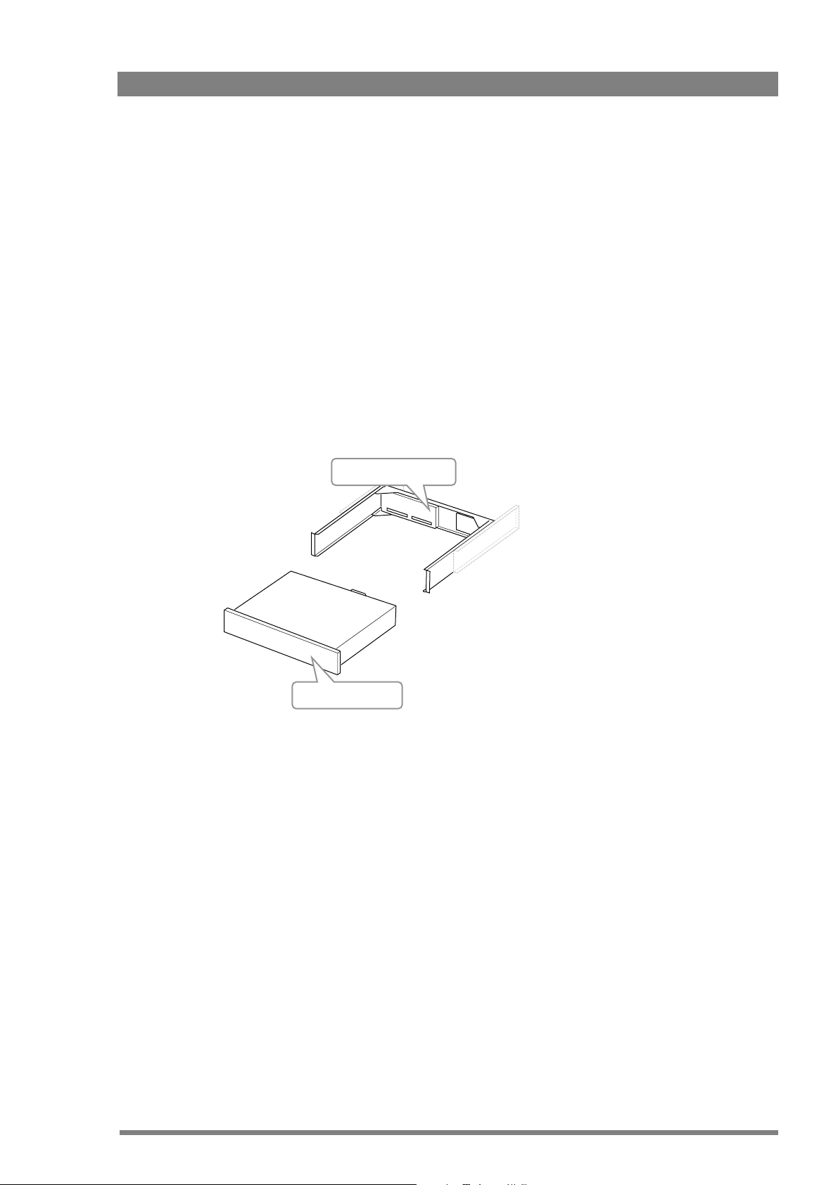
1.2.5 Cradle concept
XCU unit
UXF Cradle
The XCU UXF Fiber Series mounting system is like no other in the world. The unique cradle can
be pre-mounted and pre-wired in a 19-inch rack which ensures secure mechanical and electrical
connections including all connections to the IP infrastucture. This allows for the XCU to be
easily slided in and out whenever needed.
Each XCU UXF Fiber Series comes with one UXF Cradle, but additional cradles may be
purchased to extend usability across different environments, allowing you to quickly and easily
move XCU UXF Fiber Series between OB vans, studios, or anyplace.
Pre-mounted and pre-wired to eliminate cabling errors, the unique cradle provides on-demand
resources for fast paced productions, resulting in less set up time and more on-air time.
Compatibility with the LDX Series and many LDK Series cameras extends the cradle's
usefulness across all types of productions.
Transmission connectors can easily be exchanged during production and in the field. All other
connectors are mounted on a separate connector panel at the back of the cradle. After
disconnecting mains power and the transmission cable the XCU can be removed.
Chapter 1 - Introduction
1.3 Main features
• Flexible and multiple audio and video connectivity: the XCUs hybrid solution offers both
baseband and IP connectivity simultaneously.
• Supports 4K intoPIX TICO
uncompressed 4K is only available with LDX 86N cameras)
• The unique UXF cradle mounting concept ensures maximum flexibility with minimum setup time.
XCU UXF Fiber Series XF Transmission Fiber Base Station User’s Guide (v1.3) 13
• Transports the following digital signals from camera to XCU: main video signal, four audio
channels (including embedded digital audio), two intercom channels, control, private data
and an IP trunk.
Transports the following digital signals from XCU to camera: power, three external HD
video inputs, teleprompter signal, three intercom channels, control, private data and an IP
trunk.
• Supports all HD/3G/4K video formats: 4K50/59.94, 1080p50/59.94, 1080PsF23.98/24/25/
29.97, 1080i50/59.94, 720p50/59.94.
(R)
compression over IP and uncompressed 4K over IP. Note that
Page 14

• The Universe version supports HS/XS video formats for ultra slow motion applications:
Media Network bay
(4x SFP+ cages)
C2IP Control Network
(RJ45)
XF Transmission
(hybrid fiber)
IP Trunk (RJ45)
1080i150/179/300/359, 720p150/179/300/359, 1080p150/179 (HS/XS video signals are only
available on the baseband (BNC) outputs).
• Supports video, audio, intercom and timing over the 10 GigE Media Network infrastructure
using SFP+ output cages (SFP+ modules are not included).
• Supports discovery and registration (AMWA-NMOS IS-04) signals over C2IP.
• Full camera control via Grass Valley’s C2IP Ethernet-based control network.
• Supports general purpose 1 Gb/s IP Trunk connection between camera and XCU.
• Three channel (two-wire or four-wire) intercom system compatible with international
standards.
• Built in a compact 2 RU high, robust 19-inch rack with a reliable power unit that has low
power consumption, ideal for outside broadcast vans.
1.4 Overview of IP connections
The diagram below shows an overview of the different IP connections in a typical Media
Network system configuration:
Chapter 1 - Introduction
Baseband
connections
C2IP Control Network
XF Transmission
Media Network
IP TrunkIP Trunk
42
Camera XCU UXF
The backpanel of the XCU shows the different IP connections:
A
2
EXT1
EXT
IN
IN
T
EXT1
EXT3
U
IN
O
SIGNALS ON CONNECTORS A TO E DEPEND
ON SELECTED VIDEO MODE
REFER TO THE USER’S GUIDE
FOR SIGNAL DESCRIPTIONS
PORTA1PORT
A2
PORTB1PORT
B2
B
C ED
SIGNALLING
T
SDI 1
U
O
I 2
T
SD
U
O
BS
V
C
Public Network
(for 3rd party
XML control)
OCP
Camera
400
Connect
C2IP
TP
REF
IN
IN
P
T
T
T
REF
U
U
O
O
INTERCOM
AES 1+2AES 3+4
ETHERNET
ANALOG AUDIO OUT
AUX
MCP
450
1
2
14 XCU UXF Fiber Series XF Transmission Fiber Base Station User’s Guide (v1.3)
Page 15
Chapter 2
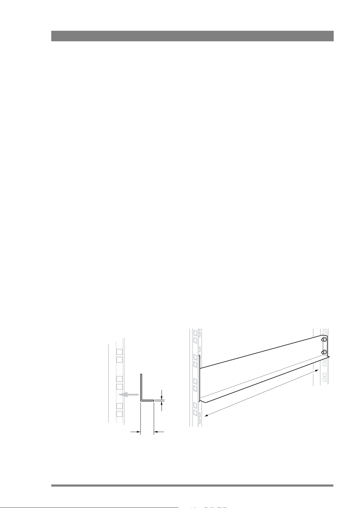
min. 30 cm (11.8 in.)
min. 12 mm (0.5 in.)
max. 2 mm (0.08 in.)
Installation
2.1 Rack installation
Chapter 2 - Installation
2.1.1 Installing rack mounting rails
The UXF Cradle can be mounted in most standard 19-inch video or IT rack types. The unit
needs two rack units (2 RU) of vertical space in the rack.
Install two L-shaped rack mounting rails (not supplied) that match your rack type. Refer to the
documentation of your mounting rails or rack for installation instructions.
• Make sure that both front and back end of the rails are attached to the rack. Allow a
minimum distance of 30 cm (11.8 in.) between the secured points.
• There should be a blind/untapped area in the front of the vertical rack beam where the
locking mechanism of the XCU engages the rack.
• The thickness of the horizontal leg of the L-shaped mounting rails must not exceed 2 mm
(0.08
in.) in order to leave enough space for more cradles to be mounted below the unit.
Below is an example of a rack mounting rail installed in a 19-inch rack. Note that your specific
situation may be different.
XCU UXF Fiber Series XF Transmission Fiber Base Station User’s Guide (v1.3) 15
Page 16
2.1.2 Installing the cradle
After mounting the rack mounting rails, install the cradle:
1. Slide the cradle into the rack so it is supported by the L-shaped mounting rails.
2. Fix the cradle to the front rack posts using four M6-screws (not supplied with the unit).
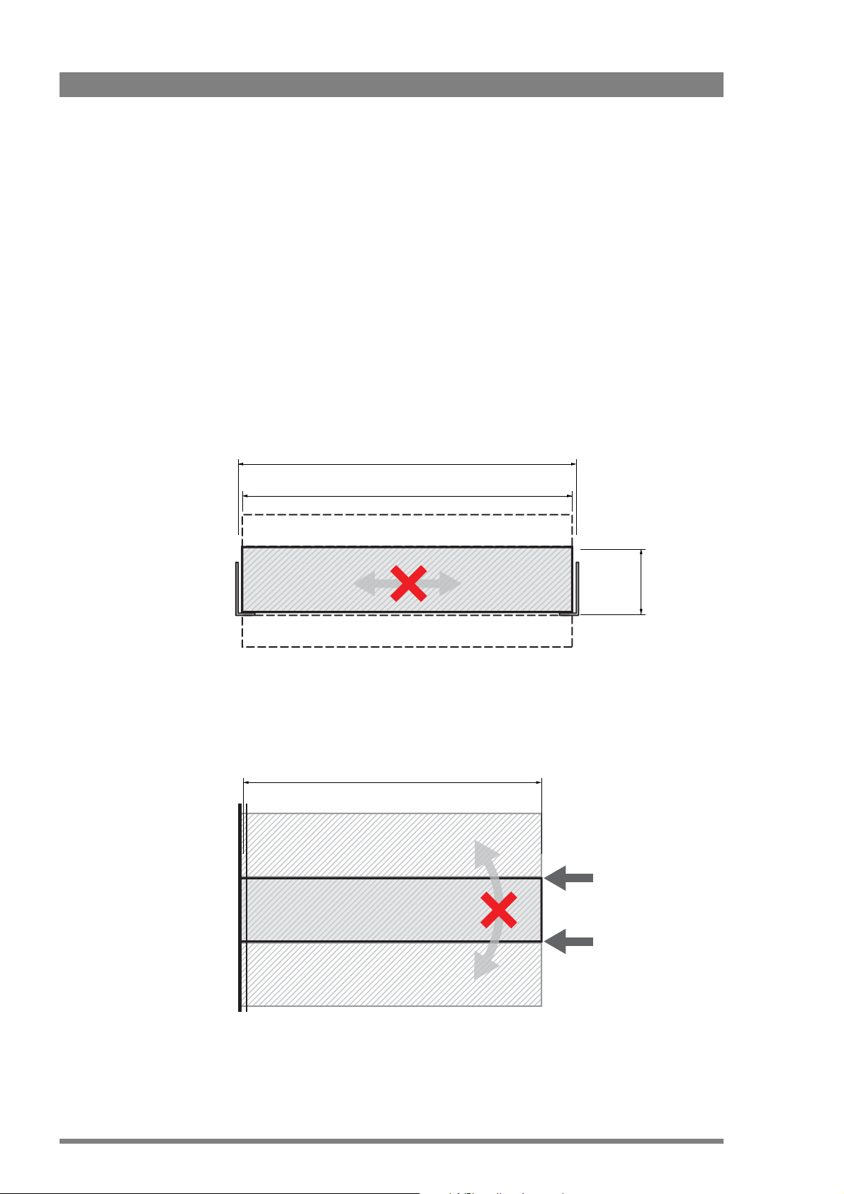
2.1.3 Transporting rack mounted XCUs
When transporting rack mounted XCUs in a flightcase make sure to take the following
precautions:
• Use proper shock absorbers for the rack to prevent damage during transport.
• To prevent any horizontal movement of the cradle and XCU during transport, make sure
there is as little horizontal clearance as possible between the cradle and the mounting
rails:
450 mm — 455 mm
Chapter 2 - Installation
438 mm
(free space)
88 mm (2 RU)
XCU
(free space)
• To prevent any vertical movement of the cradle during transport, lock up the cradle
between other units and the vertical rail stands as indicated in the illustration below. Make
sure there is enough support at the back of the unit, at a minimum distance of 400 mm
from the rack front/
400 mm
XCU or other rack device
FRONT XCU
XCU or other rack device
16 XCU UXF Fiber Series XF Transmission Fiber Base Station User’s Guide (v1.3)
Page 17
2.1.4 Connecting studio cabling
The studio cabling (Media Network, baseband video, control and intercom, studio signalling)
can now be connected according to your application and studio configuration. Refer to “Power
and Transmission” on page 88 for connectors and signals available on the cradle.
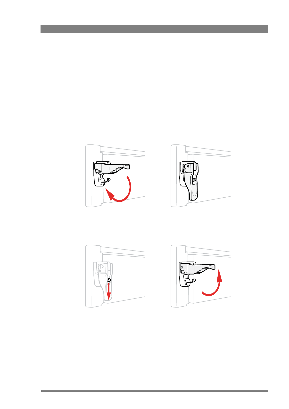
2.2 Mounting the XCU
To mount the XCU into the cradle, proceed as follows:
• Place the XCU onto the sliding rails of the cradle, slide the unit into the cradle and push
firmly.
• Push down the right and left locking handles until they snap down.
Chapter 2 - Installation
To remove the XCU from the cradle, proceed as follows:
• Hold down the springs inside the locking handles and at the same time swing them open.
• Pull out the XCU from the cradle by pulling the XCU at its sides.
• Now the transmission and mains cables can be connected. Refer to “Connector back
panel” on page 87 for connectors and signals available on the XCU.
XCU UXF Fiber Series XF Transmission Fiber Base Station User’s Guide (v1.3) 17
Page 18
2.3 Connecting the control network
☞
Note
☞
Note
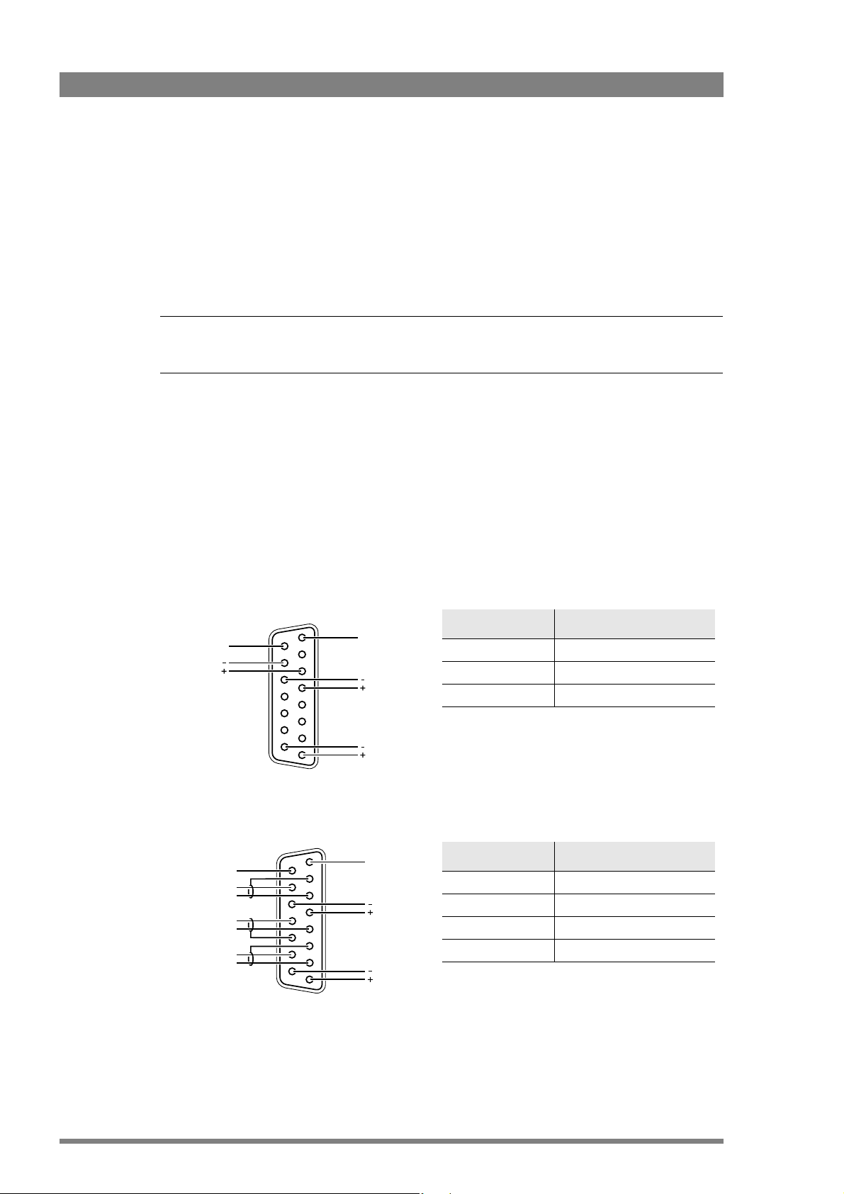
Signal Value
Signal level 0 dBu (RMS)
Load impedance 200
Voltage level max. 40 VDC
8
1
15
9
Housing
Prod
Housing
Eng in/out
Prod in/out
Signal Value
Output signal level +6 or 0 dBu (RMS) selectable
Output impedance max. 50 symmetrical
Input signal level +6 or 0 dBu (RMS) selectable
Impedance min. 9 k symmetrical
Housing
Eng in/out
Prod in/out
Housing
Prog in ret
Prog in
Prod in ret
Prod in
Eng in ret
Eng in
The XCU is connected to the control network switch or router via an Ethernet cable (straightthrough, not cross-over) via the C2IP (RJ45) connector. An OCP 400 (Operational Control Panel)
and, if required an MCP 450 (Master Control PC), are also connected to the Ethernet network
via a hub or router. An OCP 400 can also be connected directly to the XCU using a (cross-over
or a straight-through) Ethernet cable.
The IP address and other options for the Ethernet connection can be set up in the XCU menu.
By default, the Ethernet connection is set up for Auto IP configuration.
2.4 Connecting analog intercom
Connect the analog studio intercom system to the rear of the XCU (cradle). Both a two and
four-wire cabling can be used. In the
menu select the cabling system: 2wire or 4wire.
The wiring of the panel connector is shown below for two-wire and four-wire systems.
AUDIO/INTERCOM > INTERCOM > ENG > WIRE MODE
Chapter 2 - Installation
Two-wire systems
Four-wire systems
15
9
8
1
18 XCU UXF Fiber Series XF Transmission Fiber Base Station User’s Guide (v1.3)
Page 19
2.5 Connecting studio signalling
☞
Note
☞
Note
Call out send
Prev.out send
Prev.out ret.
ISO in send
ISO in return
Call in send
Call in return
5 V
Housing
Call out return
On Air send
On Air return
Audio 1 level
Audio 2 level
GND
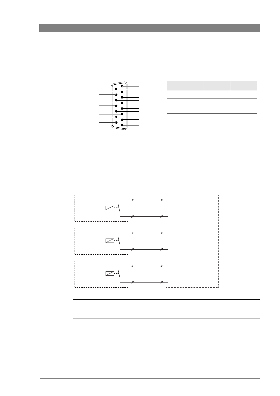
Signal Send pin Return pin
ISO 3 11
On Air 4 12
Call 2 10
ISO 1a
ISO 1b
On-Air (Tally) 1a
On-Air (Tally) 1b
Call 1a
Call 1b
ISO in ext. send (pin 3)
ISO in ext. return (pin 11)
On-Air in ext. (pin 4)
On-Air in ext. return (pin 12)
Call in ext. (pin 5)
Call in ext. return (pin 13)
External ISO signalling
(dry contact)
External On-Air signalling
(dry contact)
External Call signalling
(dry contact)
Connect the studio signalling system to the rear of the XCU (cradle). The wiring of the
signalling connector is shown below:
1
9
15
8
There are several connection methods for the ISO (On Air Yellow), On Air and Call signalling
functions: dry contact, common ground, voltage level and open circuit/voltage level.
A selection in the INSTALL > SIGNALLING INPUT menu allows you to make the activity state
of the function (Active or Inactive) correspond to a particular input signal. There are two leads
for each connection - Send and Return.
Chapter 2 - Installation
2.5.1 Dry contact
A common return (not ground!) can be used for all three functions (ISO, On Air and Call)
If a contact is closed, the corresponding function is Active or Inactive, depending on the
selection in the INSTALL > SIGNALLING INPUT menu:
XCU UXF Fiber Series XF Transmission Fiber Base Station User’s Guide (v1.3) 19
Page 20
☞
Note
☞
Note
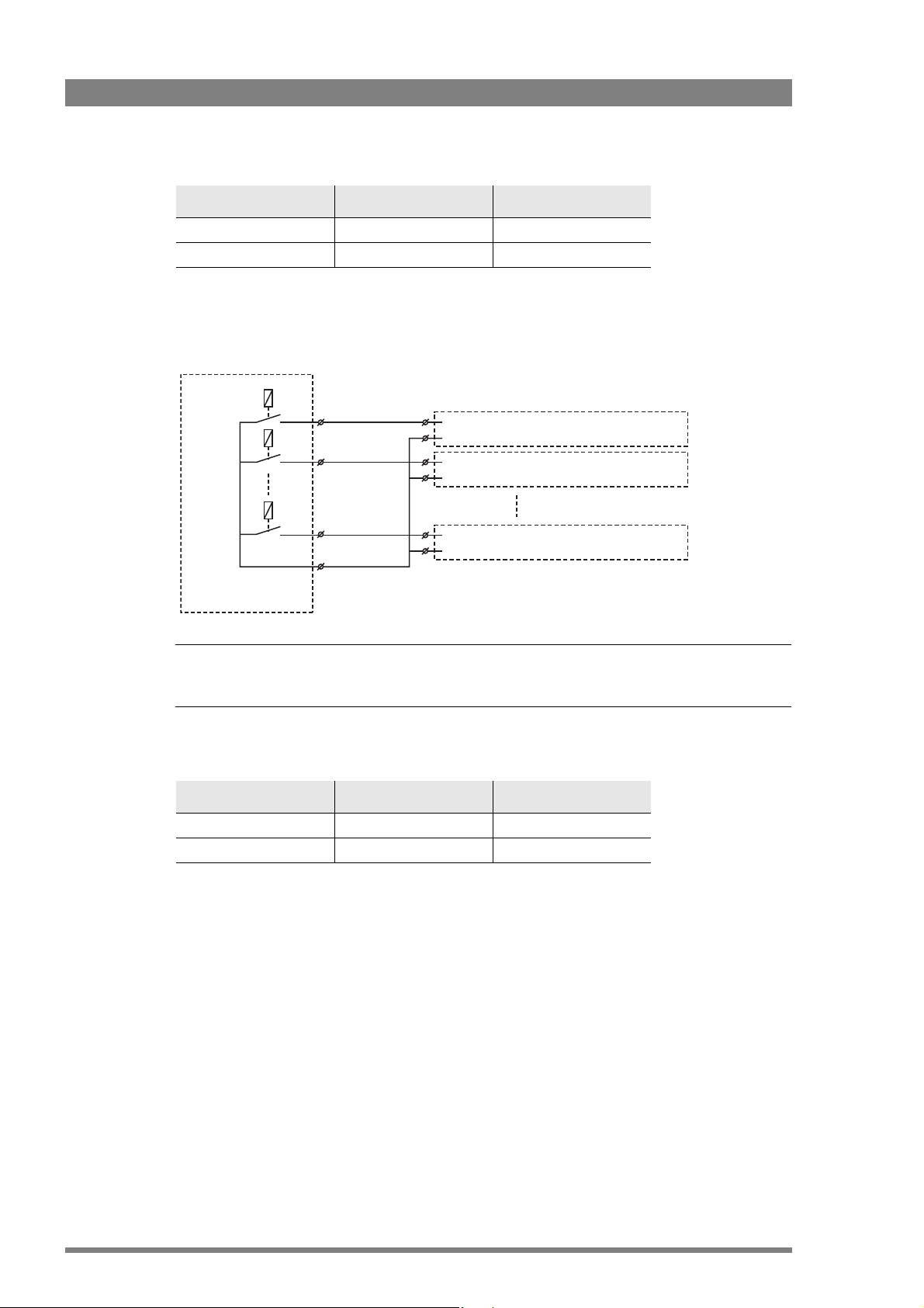
Menu setting Input is shorted: Input is open:
On-Air (Tally) 1
On-Air (Tally) 2
On-Air (Tally) n
Common
External On-Air signalling
(common contact)
On-Air in ext. send (pin 4) Signalling connector
On-Air in ext. return (pin 12) Base Station 1
Signalling connector
Base Station 2
Signalling connector
Base Station n
On-Air in ext. send (pin 4)
On-Air in ext. return (pin 12)
On-Air in ext. send (pin 4)
On-Air in ext. return (pin 12)
LH (low-high) Function is Active Function is Inactive
HL (high-low) Function is Inactive Function is Active
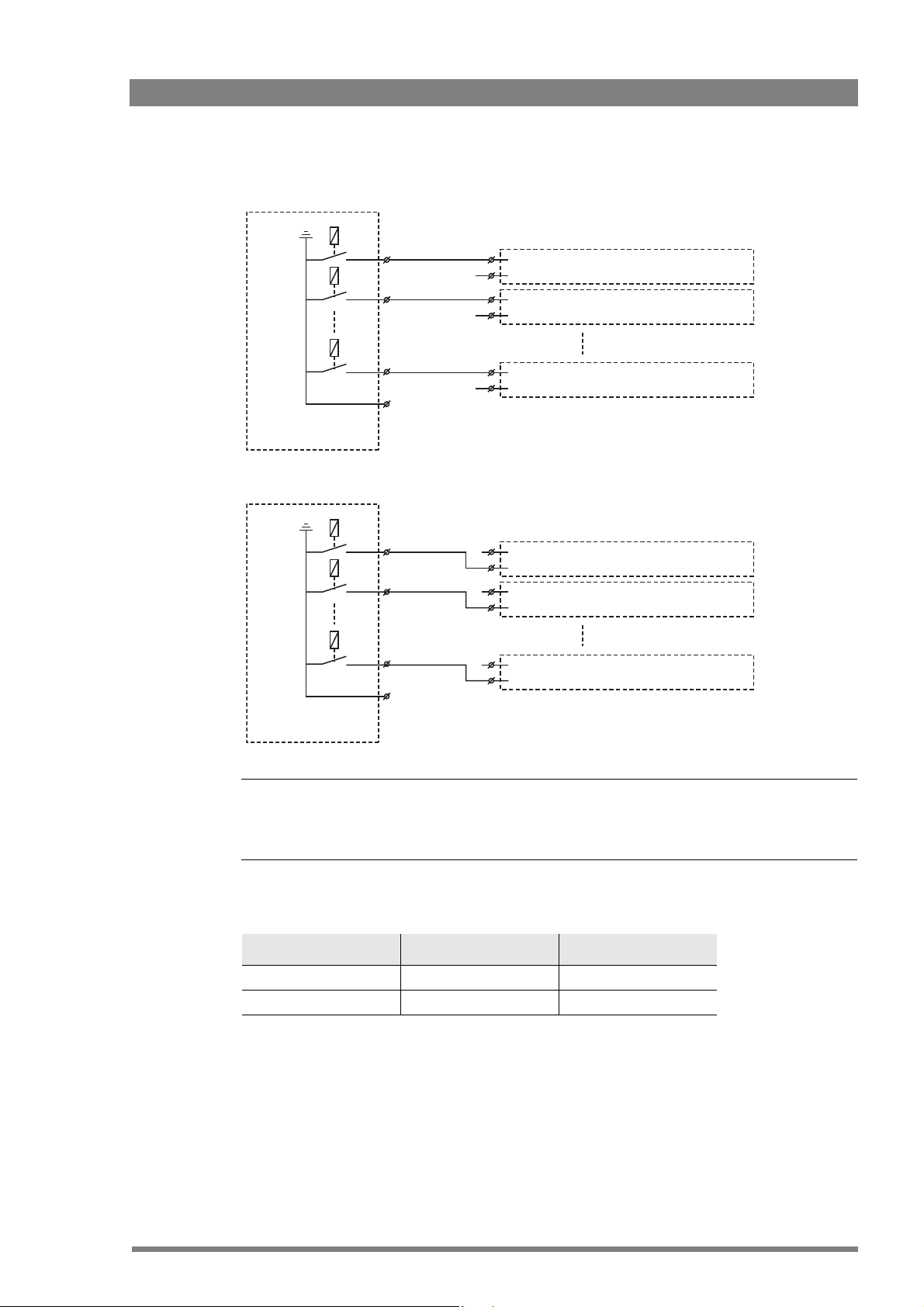
2.5.2 Dry contact with multiple XCUs
This is an example of an On Air signalling with multiple XCUs using a common contact.
Chapter 2 - Installation
Use either Send or Return only, but do not mix.
If a contact is closed, the corresponding function is Active or Inactive, depending on the
selection in the INSTALL > SIGNALLING INPUT menu:
Menu setting Input is shorted: Input is open:
LH (low-high) Function is Active Function is Inactive
HL (high-low) Function is Inactive Function is Active
20 XCU UXF Fiber Series XF Transmission Fiber Base Station User’s Guide (v1.3)
Page 21
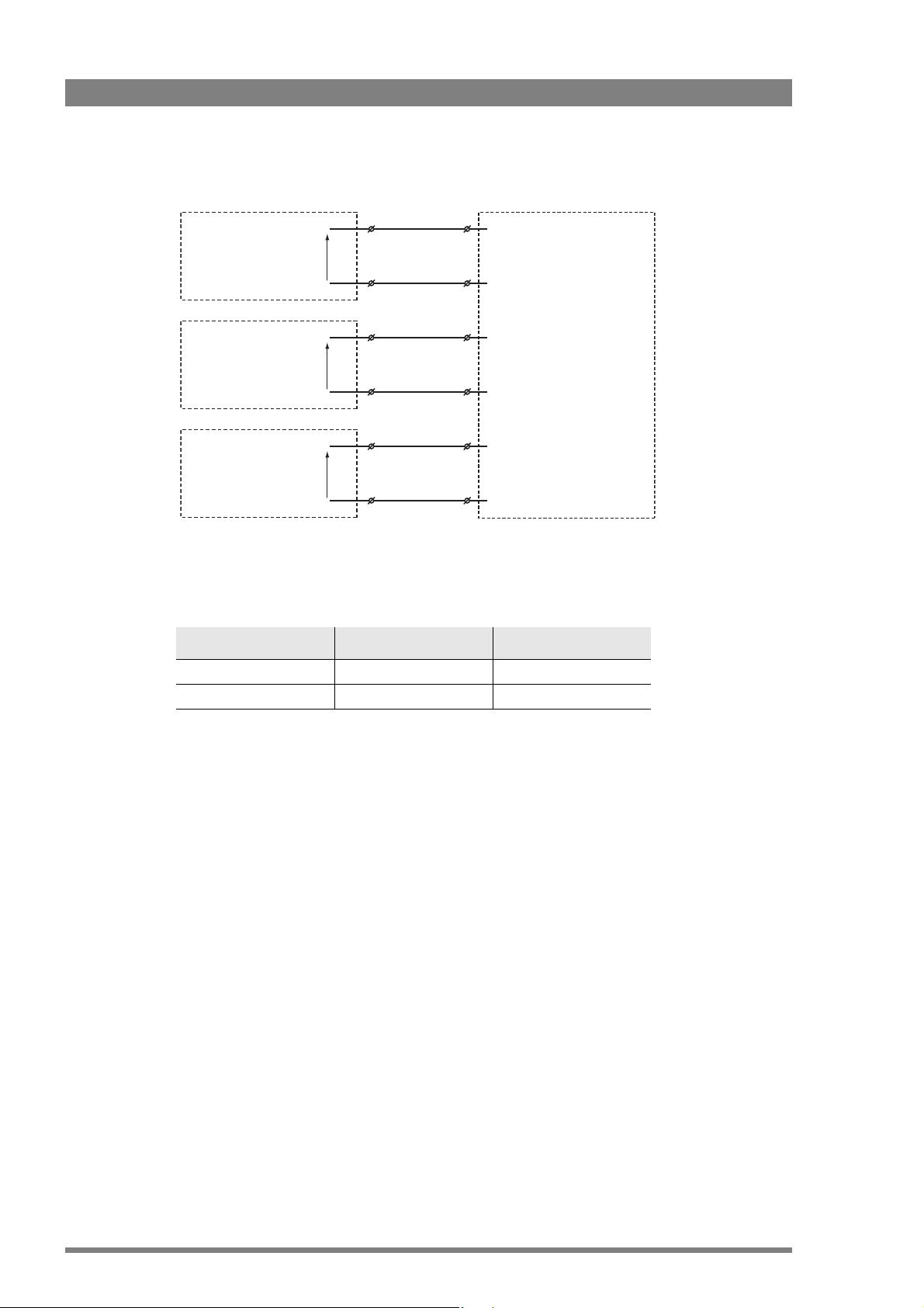
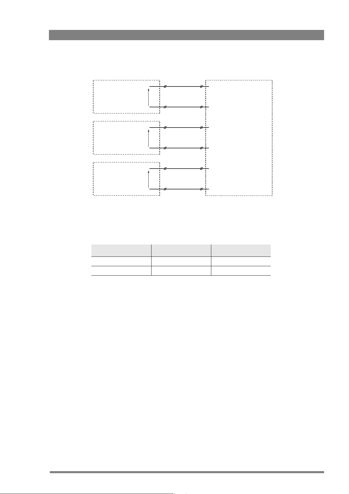
2.5.3 Common ground
☞
Note
☞
Note
On-Air (Tally) 1
On-Air (Tally) 2
On-Air (Tally) n
External On-Air signalling
(common ground contact)
On-Air in ext. (pin 4) Signalling connector
On-Air in ext. return (pin 12) Base Station 1
Signalling connector
Base Station 2
Signalling connector
Base Station n
On-Air in ext. (pin 4)
On-Air in ext. return (pin 12)
On-Air in ext. (pin 4)
On-Air in ext. return (pin 12)
Chapter 2 - Installation
Ensure that a reliable ground coupling exists between the control device ground and the XCU
UXF Fiber Series ground.
If a contact is closed, the corresponding function is Active or Inactive, depending on the
selection in the INSTALL > SIGNALLING INPUT menu:
Menu setting Input is shorted: Input is open:
LH (low-high) Function is Active Function is Inactive
HL (high-low) Function is Inactive Function is Active
XCU UXF Fiber Series XF Transmission Fiber Base Station User’s Guide (v1.3) 21
Page 22
2.5.4 Voltage level
Chapter 2 - Installation
0 .. 2.5 V
4 .. 24 V
0 .. 2.5 V
4 .. 24 V
0 .. 2.5 V
4 .. 24 V
+
DC
-
DC
+
DC
-
DC
+
DC
-
DC
ISO 1a
ISO 1b
On-Air (Tally) 1a
On-Air (Tally) 1b
Call 1a
Call 1b
ISO in ext. send (pin 3)
ISO in ext. return (pin 11)
On-Air in ext. send (pin 4)
On-Air in ext. return (pin 12)
Call in ext. send (pin 5)
Call in ext. return (pin 13)
Apply a DC voltage to the inputs (respect polarity). If the voltage is low (0 to 2.5 V), the function
is Active (or Inactive). If the voltage is high (4 to 24 V) the function is Inactive (or Active). The
function state depends on the selection in the INSTALL > SIGNALLING INPUT menu:
Menu setting Input is 0 to 2.5V: Input is 4 to 24V:
LH (low-high) Function is Active Function is Inactive
HL (high-low) Function is Inactive Function is Active
22 XCU UXF Fiber Series XF Transmission Fiber Base Station User’s Guide (v1.3)
Page 23
2.5.5 Open circuit/Voltage level
ISO 1a
Open/
4..24 V
DC
Open/
4..24 V
DC
Open/
4..24 V
DC
ISO 1b
On-Air (Tally) 1a
On-Air (Tally) 1b
Call 1a
Call 1b
ISO in ext. send (pin 3)
ISO in ext. return (pin 11)
On-Air in ext. send (pin 4)
On-Air in ext. return (pin 12)
Call in ext. send (pin 5)
Call in ext. return (pin 13)
Chapter 2 - Installation
Leave the circuit open or apply a DC voltage to the inputs (respect polarity). If the circuit is
open, the function is Active (or Inactive). If the voltage is high (4 to 24 V) the function is Inactive
(or Active).
The function state depends on the selection in the INSTALL > SIGNALLING INPUT menu:
Menu setting Input is open: Input is 4 to 24V:
OH (open-high) Function is Active Function is Inactive
HO (high-open) Function is Inactive Function is Active
XCU UXF Fiber Series XF Transmission Fiber Base Station User’s Guide (v1.3) 23
Page 24
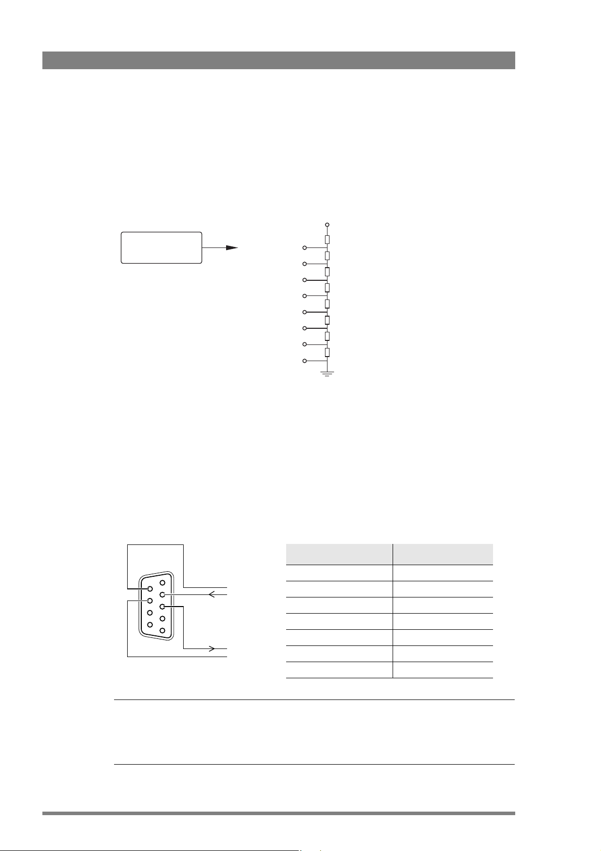
2.6 Setting external audio level
☞
Note
☞
Note
Audio 1 level (pin 6)
Audio 2 level (pin 14)
Mic/Line
Mic/5 V (pin 7)
GND (pin 15)
1k
1k
1k
1k
1k
1k
1k
1k
+4.3V
+3.7V
+3.1V
+2.5V
+1.9V
+1.3V
+0.7V
0V
-22/+4dBu
-28/+2dBu
-34/0dBu
-40/-2dBu
-46/-4dBu
-52/-6dBu
-58/-8dBu
-64/-10dBu
Private
data in
Private
data out
Function Value
Bitrate max. 100 kbit/s
Output level (high) > 4 V
Output level (low) < 4 V
Output impedance 250
Input level (high) > 2 V (max. 12 V)
Input level (low) < 2 V
Input impedance > 4.7 k
The camera audio levels for channel 1 and 2 can be externally controlled by the XCU. In the
camera system menu, go to the INSTALL
On the OCP 400, push the SETUP button and choose the Cam submenu. Use the NEXT
button to scroll to the REM AUDIO menu and select Rem. Apply a DC voltage to pins 6 and 14
of the signalling connector to control the levels of audio channels 1 and 2 respectively, as
shown in the figure below:
Chapter 2 - Installation
> AUDIO > AUDIO GAIN MODE item and select Ext.
2.7 Using private data
24 XCU UXF Fiber Series XF Transmission Fiber Base Station User’s Guide (v1.3)
The actual audio level depends on the setting of the switches at the back panel of the camera
adapter. The minimum input sensitivity for nominal output level is -64 dBu for microphone
levels and -32 dBu for line levels. Input sensitivity can be selected with steps of 6 dB.
Private data channels can be used for sending serial data via the transmission cable. For
example, electronic scriptboard or character data for a video display unit or pan and tilt data can
be transmitted to the camera.
5
9
4
8
3
7
2
6
1
Propagation-delay times vary with cable length, especially if a return signal is involved. At
max.lengths the total delay is at least 25 μs and can be more than 30 μs depending on the type
of cable. The duty cycle difference between input and output is max. 5%.
Page 25
Chapter 3
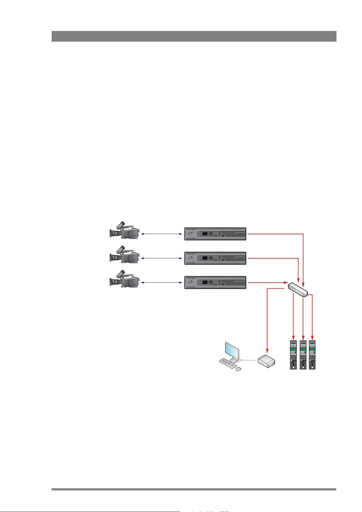
XCU 1
XCU 2
XCU #n
Camera 1
Camera 2
Camera #n
OCP 400
C2IP
Camera Connect
Network
switch
44
45
46
Configuration
3.1 Studio C2IP configuration
Below is a typical basic C2IP (Camera Control) network with multiple camera systems, control
panels and a Camera Connect unit.
Chapter 3 - Configuration
XCU UXF Fiber Series XF Transmission Fiber Base Station User’s Guide (v1.3) 25
Page 26
3.2 Setting the camera number
Communication
Transmission
Camera Power
Cable
PowerOn Air
XF Fiber
42
1 32
4 5
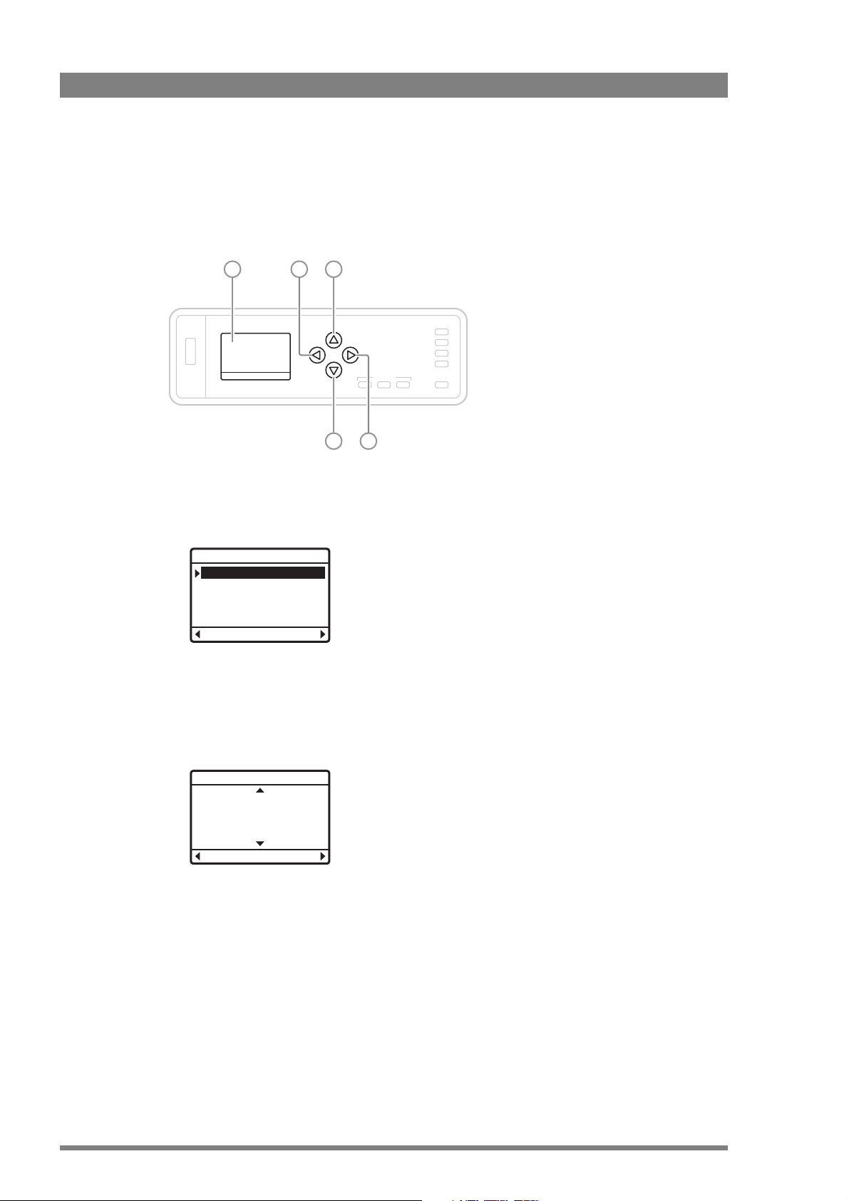
Graphic display Back Up
ForwardDown
SelectBack
Make selection:
Change camera number
Menu (Monitoring)
Menu (XCU Display)
OkCancel
Camera number
42
The front navigation panel is used to display and set the camera number, to display operational
and diagnostic information and to access and navigate the internal XCU menu.
Chapter 3 - Configuration
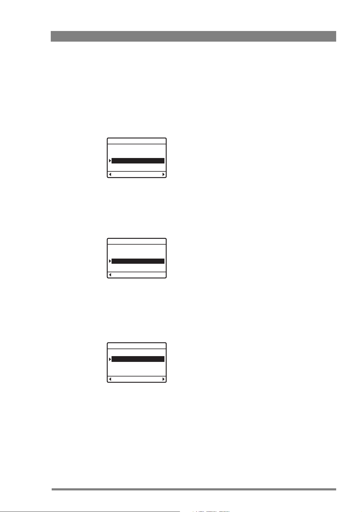
• Push and hold the Forward button [5] for two seconds until the following selection menu
appears:
• Select the Change camera number option and push the Forward button. Or push the
Back button [2] to return to the main display status.
• Use the Up [3] and Down [4] buttons to select the camera number. Push the Forward
button to confirm the settings or push the Back button to cancel the selection.
26 XCU UXF Fiber Series XF Transmission Fiber Base Station User’s Guide (v1.3)
Page 27
3.3 Accessing the XCU menu
SelectBack
Make selection:
Change camera number
Menu (Monitoring)
Menu (XCU display)
3.3.1 Using the front panel and display
The easiest way to operate the XCU menu is by using the front panel and display.
• Push and hold the Forward button [5] for two seconds until the following selection menu
appears:
Make selection:
Change camera number
Menu (Monitoring)
Menu (XCU display)
SelectBack
• Select the Menu (XCU Display) option and push the Forward button to select. Or push
the Back button to return to the main display status.
• The XCU Menu appears. Use the Up, Down buttons to scroll through the menu items,
Back to go one level up and Forward to open a submenu or to enter a value when a
function is selected. The function value is shown in the bottom right of the display.
Chapter 3 - Configuration
Timing
H Phase
IP Video Out
UHD Out
TICO Out
976
3.3.2 Using the front panel and the Monitoring output
• Connect a viewing monitor to the Monitoring output of the XCU.
• Push and hold the Forward button [5] for two seconds until the following selection menu
appears:
• Select the Menu (Monitoring) option and push the Forward button to select. Or push the
Back button to return to the main display status.
XCU UXF Fiber Series XF Transmission Fiber Base Station User’s Guide (v1.3) 27
Page 28
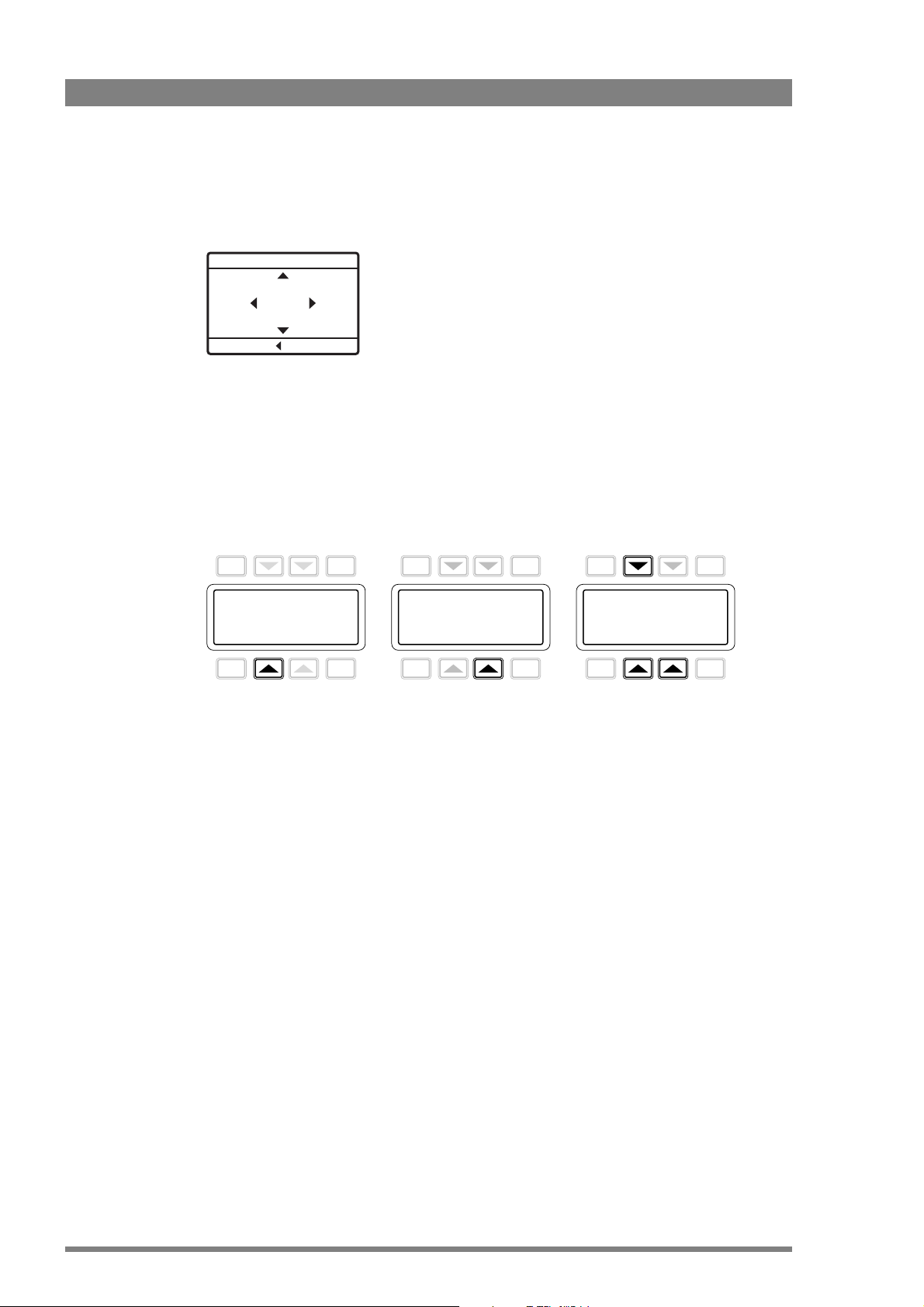
• The navigation pad appears. Use the Up, Down and Forward buttons to navigate the XCU
XCU Menu control
to ExitHold
TOGGLE
PREV NEXT
EXIT
Menu
TOGGLE
PREV NEXT
EXIT
DOWNUPSELECT
menu. The menu text appears on the Monitoring output(s) of the XCU. Push the Back
button to leave the menu.
3.3.3 Using the OCP 400 operation control panel
The OCP 400 can be used to access the XCU menu remotely:
• Connect a viewing monitor to the Monitoring output of the XCU.
• Push the SETUP MENU button on the OCP 400 to open the setup menu.
• Push the Selection button to choose the BS (= XCU) menu.
Chapter 3 - Configuration
EXIT
Diag
BS
PREV NEXT
TOGGLE
OCP
Cam
• Push the Selection button enter the menu.
• The menu appears on the Monitoring output of the XCU. Use the appropriate selection
buttons to navigate the menu. You can also use the rotary contol on the OCP
400 to move
up or down through the menu.
28 XCU UXF Fiber Series XF Transmission Fiber Base Station User’s Guide (v1.3)
Page 29

3.4 Navigating the menu
The XCU menu is used for configuring the unit. As there are a large number of functions and
setup options available, it may require some time to become familiar with them all. The menu
is available on the Monitoring output or on the XCU front display.
3.4.1 Entering the menu
Use the navigation panel on the XCU UXF Fiber Series or the OCP 400 to access the XCU
menu. The functions of the XCU are grouped into menus and sub-menus. When accessed, the
main menu appears on the monitor outputs:
MENU OFF
Chapter 3 - Configuration
Video
Monitoring
Audio/Intercom
Install
Security
Root
Diagnostics
The main menu screen shows five items and the name of the menu (at the bottom). One or
more item can be hidden but become visible when you scroll down. A cursor shows your
position in the menu. Use the Up and Down buttons to move the cursor up and down.
3.4.2 Finding your way
Use the navigation buttons to move the cursor through the menu items. If a double arrow (>>)
is visible, then pressing the Select button brings you one level lower in the menu system. Only
five items are visible in each menu. Scroll up or down to see more items.
When you first enter a menu (other than the main menu) the cursor is positioned next to the
first item. The TOP and PREVIOUS entries are not immediately visible but are located above
the first item. Use the control to scroll up to them.
• Select TOP to bring you back to the Main menu.
>>
>>
>>
>>
>>
>>
• Select PREVIOUS to go back to the menu that you were in before the current one.
TOP
PREVIOUS
Cam Conn
Alias
Device ID
Timing
Time/Date
Install
Signalling input
C2IP Network
Media Network
XCU UXF Fiber Series XF Transmission Fiber Base Station User’s Guide (v1.3) 29
>>
Jim
XCU1
>>
>>
>>
>>
>>
Page 30

The System menu above shows the items displayed when you first enter the menu and the
other items that are available by scrolling up or down.
3.4.3 Leaving the menu
If you are deep within the menu structure, follow these steps to leave:
• If necessary move the cursor to the left column.
• Scroll upwards until the cursor points to TOP (this is the main menu).
• Press the Select button; the cursor now points to the Menu Off item of the Main menu.
• Press the Select button to leave the menu.
This is the recommended way of leaving the system menu. The menu system disappears after
a few seconds when you stop navigating. This delay can be set in the MONITORING > MENU.
However, when you enter the menu again you enter at the last position of the cursor and not at
the top of main menu. To prevent confusion the next time you enter the system menu, it is
advisable to leave the system menu by returning to the main menu (TOP) and selecting MENU
OFF.
Chapter 3 - Configuration
3.4.4 Making changes
To find out where to change a function, consult “XCU menu reference” on page 63 to find out
under which menu group or subgroup the function is located. If the cursor points to an item
(and there are no double arrows to indicate a sub-menu) then the item pointed to has a value.
The value can be:
• a toggle value (only two values, for example Yes or No)
• a list value (more than two values)
• an analog value (variable from 00 to 99)
• or unavailable (---).
If the value is unavailable it cannot be changed. This is indicated by three dashes (---). This can
occur, for example, when a function is switched off. The analog values associated with that
function are then unavailable. If there are only two values associated with the function, then
pressing the Select button toggles between these two values. If a value is displayed next to a
function that is one of several possible values, then pressing the Select button places the
cursor in a list menu indicating the value currently selected. Use the Up and Down buttons to
point to a new value. Press the Select button to return the cursor to the function list. If an
analog value is displayed next to a function name, pressing the Select button places the cursor
in front of the value and the navigation control is used to change the analog value. Press the
Select button to return the cursor to the function list.
3.4.5 User levels
There are four user levels: user 0, user 1, user 2 and user 3. The purpose of the user levels is to
restrict the set of functions which can be changed by whoever is operating the unit. User level
0 is a special protection level which locks most of the operational controls of the camera. Use
this level to ensure that a camera that has been set-up is not tampered with. User level 0 is not
normally used for operational purposes as it is too restrictive for normal circumstances. The
recommended minimum user level is 1. For full control set the level to 3. When you switch off
the power, the access rights that were obtained by the use of the PIN code are disabled and
the camera starts at the assigned user level when switched on again.
30 XCU UXF Fiber Series XF Transmission Fiber Base Station User’s Guide (v1.3)
Page 31

3.5 Setting up intercom
☞
Note
☞
Note
The studio camera systems offer extensive intercom facilities between camera operator (plus
tracker) and XCU (studio). To help you set up and operate the intercom system, the following
controls are available:
• XCU menu system
• Camera head menu system
• Camera rear panel
• Camera head switches
When setting up a system it is more convenient to use an OCP 400 or Camera Connect to set
your preferences in both the XCU and camera head menus.
Intercom settings are stored in the non-volatile memory of the cradle so they keep tied to the
rack position along with the intercom wiring.
Chapter 3 - Configuration
3.5.1 Studio interface setup
Intercom source selection
In the AUDIO/INTERCOM > INTERCOM menu, use SOURCE to select the source for the
intercom system (valid for all channels).
• Analog — intercom channels come from the 15-pin SubD XCU intercom connector at the
back panel of the XCU. Refer to
• Ext1 — intercom channels come from embedded SDI audio of external video input 1
(EXT1).
The AUD2IP and IP2AUD mapping structure below is used for embedding the audio/
intercom signals into the ST2022-6 Main video and monitoring stream and for deembedding of the Ext1 ST2022-6 input stream:
Audio slot: 0 1 2 3 4 5
Lane 1 (AUD2IP) Audio 1 Audio 2 Audio 3 Audio 4 Intercom 1 Intercom 2
Lane 1 (IP2AUD) Intercom 1 Spare 1 Audio 1 Audio 2 Intercom 2 Intercom 3
Audio 1 an Audio 2 an Audio 1 AES Audio 2 AES Engineering Engineering
Program 1 (Program 2) (AES Ext1) (AES Ext2) Production Production
“Intercom connector” on page 102.
(Audio slots 6 to 15 are unused)
Intercom wire mode
A four-wire or a two-wire studio system can be connected to the XCU. In the AUDIO/
INTERCOM > INTERCOM menu, use WIRE MODE to select the wire mode the Engineering (Eng),
Production (Prod) and Program (Prog) channels. By default these values are set to four-wire.
XCU UXF Fiber Series XF Transmission Fiber Base Station User’s Guide (v1.3) 31
Page 32

Isolate
☞
Note
☞
Note
The isolate function disconnects the XCU intercom from the studio system.
Levels
In the four-wire mode the menu gives you a choice of either a 0 dB or a +6 dB signal level for
each intercom channel. In the two-wire mode this level is always set to 0 dB.
You can also set sidetone (feedback) volume levels for both Engineering and Production
channels in this menu.
3.6 Timing
3.6.1 Synchronization
To synchronize the XCU apply a valid reference (HD Tri-Level sync or SD Black Burst) signal to
the REF IN BNC connector at the back panel.
Chapter 3 - Configuration
3.6.2 Shifting output signals
All main HD Video, SD and monitoring output signals coming from the XCU are in phase. Still,
due to different cable lengths or other delays, the signals from different XCUs can be out of
phase when they are connected to a video switcher or router.
This variation in phase can be compensated for in the XCU by using horizontal phase (H-phase)
adjustment. Go the INSTALL > TIMING menu and adjust the H-PHASE item.
The phase shift can be further adjusted in the INSTALL > TIMING > SHIFT menu. Use the
PIXELS and LINES items to shift the signals over one or more pixels and one or more lines,
respecively. The maximum shift is one frame.
Service access is needed to access the Shift Pixel and Lines items.
32 XCU UXF Fiber Series XF Transmission Fiber Base Station User’s Guide (v1.3)
Page 33

3.7 Color bars
☞
Note
☞
Note
Split bar (according to
SMPTE RP215)
Full bar (with grey bars
at the sides)
For setup and test purposes, the XCU can generate a color bar signal at the main video outputs
(baseband connectors and Media Network simultaneously).
The color bar also appears when no camera is connected and no valid video signal is received
(unless the the INSTALL > NO SIGNAL item is set to Black).
• To turn on the XCU color bar, go to the VIDEO > COLOR BAR > COLOR BAR item and select
On.
• The color bar type can be selected with the VIDEO > COLOR BAR > COLOR BAR TYPE
item. Two HD color bar types are available: Split (default) and Full.
Chapter 3 - Configuration
XCU UXF Fiber Series XF Transmission Fiber Base Station User’s Guide (v1.3) 33
Page 34

Chapter 3 - Configuration
34 XCU UXF Fiber Series XF Transmission Fiber Base Station User’s Guide (v1.3)
Page 35

Chapter 4 - Media Network configuration
Main
ST2022-6
Monitor
ST2022-6
10 Gb/s
Ethernet
10 Gb/s
Ethernet
Main 3G
ST2022-6
AES67 Audio/
intercom
AES67 Audio/
intercom
Ext1
ST2022-6
Ext2
ST2022-6
TP
ST2022-6
Multicast (+ IGMP)
Unicast
PTP (2059, slave)
Multicast (+ IGMP)
Unicast
PTP (2059, slave)
Return video formats:
Ext 1/2: 3G/HD/SD-SDI (No TICO)
TP: SD-SDI (No analog)
IP Streams can be enabled/disabled
Main video: HD/3G/4K-TICO
Audio (1+2+3+4) embedded
Intercom (Prod + Eng) embedded
Monitoring video: HD
Audio (1+2+3+4) embedded
Intercom (Prod + Eng) embedded
Main video: 4K in 3G
Audio (1+2+3+4) embedded
Intercom (Prod + Eng) embedded
Audio (1+2+3+4; RFC3551; L16/L24)
Intercom (Prod + Eng; RFC3551; L16/L24)
Ext 1
Intercom (Prog + Prod + Eng) de-embedded
Audio (1+2; RFC3551; L16/L24)
Intercom (Prod + Eng (+2nd Prog);
RFC3551; L16/L24)
Ext 2
Teleprompter
Media Network 10 Gb/s
Chapter 4
Media Network configuration
4.1 Overview of IP streams
Below is an overview diagram of the IP streams in the Media Network. Depending on video
mode, protocol settings and signal switches, some streams may be present or not.
XCU UXF Fiber Series XF Transmission Fiber Base Station User’s Guide (v1.3) 35
Page 36

4.2 Camera Connect
☞
Note
☞
Note
☞
Note
☞
Note
☞
Note
☞
Note
You can use the XCU menu (either via the front panel interface on the XCU or via the OCP 400
BS remote menu) to set up the Media Network but it is more convenient to use Grass Valley’s
Camera Connect application.
Camera Connect is a part of the MCP 450 Master Control PC package.
Refer to the MCP 450/Camera Connect documentation for detailed setup and configuration of
your camera control network including the MCP 450.
To configure the Media Network follow these steps:
• On the MCP 450, open the browser and acces the Camera Connect web interface:
Chapter 4 - Media Network configuration
• Enter user name and password. The default login name is admin and the password admin.
• Click Login. The Camera Connect user interface is shown.
All user entries in the Camera Connect application are case sensitive.
• Click the Configuration tab at the top op the page; a row of sub tabs appears. The
following sub tabs are used to configure the Media Network: PTP, IP Media Port A, IP
Media Port B, IP Main A, IP Main B, IP Mon\Live, IP Video In, IP Audio and IP Intercom.
Click the double arrows at the right to access more tabs:
The IP configuration tabs list only camera systems that are IP enabled.
36 XCU UXF Fiber Series XF Transmission Fiber Base Station User’s Guide (v1.3)
Page 37

4.3 Media Network setup
☞
Note
☞
Note
Off
port is not in use.
indicates a connection between the port and a 10 G IP device (e.g. a switch)
no connection
4.3.1 Media Network local ports setup
The list of camera systems is shown, sorted by camera number. Click the IP Media Port A tab:
here you can configure (local) IP addresses, subnet mask and default gateway for Media Port
A.
Chapter 4 - Media Network configuration
The indicator(s) in front of the IP addresses for port A1 and port A2 show the status of the
physical IP network connection:
A green light does not mean that there is a correct communication link between XCU and the
10 G IP device.
Refer to the “Media Network bay” on page 89 for the location of the Media Network ports at
the back panel of the XCU.
Click the camera system you want to set up. A popup window appears and you can edit the
following parameters:
XCU UXF Fiber Series XF Transmission Fiber Base Station User’s Guide (v1.3) 37
Page 38

Chapter 4 - Media Network configuration
☞
Note
☞
Note
Off
(Sub) stream is disabled
(Sub) stream is enabled and stream is active.
(Sub) stream is enabled but stream is not active.
Port A1 IP — this is the local IP address of Port A1 in the Media Network. It is recommended
to use an IP address in the 10.11.5.xxx range.
Port A2 IP — this is the local IP address of Port A2 in the Media Network. It is recommended
to use an IP address in the 10.11.5.xxx range.
Subnet mask — for most situations the subnet mask is set to 255.255.0.0. This is also the
default value.
Default gateway — for most situations the default gateway is set to 10.11.5.1. This is also the
default value.
Do not use IP address 10.11.5.1 as it is already in use for the default gateway. If you still want to
use this address then you must enter a different default gateway.
Make sure to set unique IP addresses for each camera system in the Media Network to avoid
network conflicts.
Media Network port B setup
The IP Media Port B tab is identical to the Port A tab and contains all settings for Port B which
is used for a secondary stream to operate in IP Redundancy mode. Refer to “IP Redundancy”
on page 53 for more information about IP Redundancy.
4.3.2 Main video
In the IP Main A tab you can set up IP address and port number for the Main video outgoing
stream for the primary Media Network Port. The transport protocol for Main video is also
selected in this tab.
Present indicator for Main video (sub) stream:
38 XCU UXF Fiber Series XF Transmission Fiber Base Station User’s Guide (v1.3)
Page 39

Chapter 4 - Media Network configuration
☞
Note
☞
Note
☞
Note
☞
Note
Normally, Main video is sent as a single IP stream but with uncompressed 4K the signal is split
into four (sub)streams. Refer to the “Main video in 4K uncompressed mode” on page 39 for
detailed information about configuring a 4K uncompressed Main video stream.
Click the camera system you want to configure. A popup window appears in which you can set
the following parameters:
Main Video
Enabled — selects whether the Main video is included in the Media Network stream and to
which port the stream is sent:
Port A: Main video is routed to Port A (default setting).
Port A+B: Main video is routed to both Port A and B to enable redundant network
operation. Refer to “IP Redundancy” on page 53 for more information about IP
Redundancy.
Off: Main video is NOT inserted into the Media Network stream (this is also indicated with
the indication off in front of stream 1).
Protocol — this is the transport protocol for Main video. Select either ST2022-6 (‘embedded
SDI with audio and anciliary data over IP’) or ST2110-20 (‘Video essence over IP’).
Stream 1 (port A):
Dest. IP address — the destination IP address to which the stream is sent.
Dest. Port — the destination port number for the stream.
When the same IP address is used for the Main video, Monitoring video and/or Live video
streams, the port numbers for each stream MUST be set to different values.
4.3.3 Main video in 4K uncompressed mode
The 4K uncompressed mode is only available in combination with the LDX 86N camera. Also
make sure that the camera is running in 4K video mode.
XCU UXF Fiber Series XF Transmission Fiber Base Station User’s Guide (v1.3) 39
Page 40

Chapter 4 - Media Network configuration
In the IP Main A tab you can set up IP addresses and port numbers for the four (sub)streams of
the 4K uncompressed Main video outgoing stream. The transport protocol for Main video is
also selected in this tab.
When the window does not display the four (sub)streams as indicated in the example above,
the compression mode needs to be set to Uncompressed first. To do this, click the camera
system you want to configure. A popup windows appears. Set the 4K Output item to Uncompr
(indicated in red below) and click OK to activate the changes.
40 XCU UXF Fiber Series XF Transmission Fiber Base Station User’s Guide (v1.3)
Page 41

Chapter 4 - Media Network configuration
With the 4K Output compression mode set to Uncompr, click the camera system you want to
configure. A popup window appears in which you can set the following parameters:
Main Video
Enabled — selects whether the Main video is included in the Media Network stream and to
which port the stream is sent:
Port A: Main video is routed to Port A (default setting).
Port A+B: Main video is routed to both Port A and B to enable redundant network
operation. Refer to “IP Redundancy” on page 53 for more information about IP
Redundancy.
Off: Main video is NOT inserted into the Media Network stream (this is also indicated with
the indication off in front of stream 1).
Protocol — this is the transport protocol for IP Main Video. Select either ST2022-6 (‘embedded
SDI with audio and anciliary data over IP’) or ST2110-20 (‘Video essence over IP’).
4K Output — in this case Uncompr is selected.
Stream config — defines how streams 2,3 and 4 are configured, based on settings for stream
1:
AutofillIP: the IP addresses for stream 2, 3 and 4 are automatically filled in based on the
entered IP address for stream 1. The last digit of the IP address for Stream 1 is increased
by 2 for the subsequent streams.
AutofillPrt: the port numbers for streams 2, 3 and 4 are filled in based on the port number
entered for stream 1. The port number is subsequently raised by 1.
In case of a single destination unicast/multicast address, the port number of the first
stream is entered and the port number for the subsequent streams is increased by 1.
XCU UXF Fiber Series XF Transmission Fiber Base Station User’s Guide (v1.3) 41
Page 42

Chapter 4 - Media Network configuration
☞
Note
☞
Note
☞
Note
☞
Note
This is not applicable for receivers with two 10G ports. A single IP destination address causes
the Ethernet switch to flood both ports with all four streams. This can only be used for 25G and
40G port receivers.
When Manual (default setting) is selected you can enter the IP addresses and port
numbers manually for all four (sub)streams.
For streams 1 to 4
IP address — the destination IP address to which the stream is sent. By default, use four
different multicast IP addresses.
Port — the destination port number for the stream.
When the same IP address for Main Video, Monitoring video and or Live video is used, the port
numbers for each stream MUST be set to different values.
42 XCU UXF Fiber Series XF Transmission Fiber Base Station User’s Guide (v1.3)
Page 43

4.3.4 IP Mon\Live tab
☞
Note
☞
Note
The list of camera systems is shown, sorted by camera number. In this tab Monitoring video
and/or Live video outputs can be set up.
Live video is only present when HDR is enabled and/or when the XCU is running in a 4K video
mode.
Chapter 4 - Media Network configuration
Click the camera system you want to set up. The edit popup window appears in which you can
edit the following parameters:
Monitoring video
Enabled — selects whether the Monitoring video is included in the Media Network stream
and to which port the stream is sent:
Port A: Monitoring video is routed to Port A (default setting).
XCU UXF Fiber Series XF Transmission Fiber Base Station User’s Guide (v1.3) 43
Page 44

Chapter 4 - Media Network configuration
☞
Note
☞
Note
☞
Note
☞
Note
Port A+B: Monitoring video is routed to both Port A and B to establish a redundant
network connection. Refer to “IP Redundancy” on page 53 for more information about IP
Redundancy.
Off: Monitoring video is NOT inserted into the Media Network stream (this is also
indicated with the indication off in front of Stream 1).
Protocol — this is the transport protocol for Monitoring video. Select either ST2022-6
(embedded SDI with audio and anciliary data over IP) or ST2110-20 (Video essence over IP).
Port A output
Dest. IP address — the destination IP address for Port A to which Monitoring video is sent.
Dest. Port — the destination port number for Port A for Monitoring video.
Port B output
Port B is only used when redundant operation is enabled.
Dest. IP address — the destination IP address for port B to which Monitoring video is sent.
Dest. Port — the destination port number for Port A for Monitoring video.
Live video
Live video is only present when HDR is enabled and/or when the XCU is running in a 4K video
mode.
Enabled — selects whether the Live video is included in the Media Network stream and to
which port the stream is sent:
Port A: Live video is routed to Port A (default setting).
Port A+B: Live video is routed to both Port A and B to establish a redundant network
connection. Refer to “IP Redundancy” on page 53 for more information about IP
Redundancy.
Off: Live video is NOT inserted into the Media Network stream.
Protocol — this is the transport protocol for Live video. Select either ST2022-6 (embedded SDI
with audio and anciliary data over IP) or ST2110-20 (Video essence over IP).
Port A output
Dest. IP address — the destination IP address for Port A to which Live video is sent.
Dest. Port — the destination port number for Port A for Live video.
44 XCU UXF Fiber Series XF Transmission Fiber Base Station User’s Guide (v1.3)
Page 45

Port B output
☞
Note
☞
Note
Port B is only used when IP Redundancy is in operation.
Dest. IP address — the destination IP address for port B to which Live video is sent.
Dest. Port — the destination port number for Port B for Live video.
4.3.5 IP Video In tab
The list of camera systems is shown, sorted by camera number. In this tab the incoming
External 1, External 2 and Teleprompter video inputs can be set up.
Chapter 4 - Media Network configuration
The Extern 1, Extern 2 and Teleprompter columns show the present indicator, transport
protocol, port number and Multicast IP address for each incoming video stream.
XCU UXF Fiber Series XF Transmission Fiber Base Station User’s Guide (v1.3) 45
Page 46

Chapter 4 - Media Network configuration
Tip
✎
no indication
Steam is not present or not available.
Yes
Steam is present.
Unsupported format
Stream is present but audio has an unsupported format.
No
Stream is not present or an error has occured.
Click the camera system you want to set up. The edit popup window appears in which you can
edit the following parameters:
For Extern 1, Extern 2 and Teleprompter:
Present — the present indicator can have the following status indications:
Protocol — this is the expected transport protocol for the incoming video stream. Select either
ST2022-6 or ST2110-20;
Port — the receiving port number for the video stream.
Multicast — Yes or No. Select whether you want to use multicast or not.
Multicast IP — the receiving multicast IP address (when Multicast = Yes)
It is recommended to use port numbers in the 1000 .. 49152 range.
46 XCU UXF Fiber Series XF Transmission Fiber Base Station User’s Guide (v1.3)
Page 47

4.3.6 IP Audio tab
The list of camera systems is shown, sorted by camera number. In this tab the outgoing and
incoming IP Audio streams can be set up.
The columns show relevant information for both outgoing (on Ports A and B) and incoming
streams.
Click the camera system you want to set up. The edit popup window appears in which you can
edit the following parameters:
Chapter 4 - Media Network configuration
AES67 Audio Out
Enabled — selects whether AES67 Audio output is included in the Media Network stream and
to which Port the stream is sent:
Port A: AES67 Audio is routed to Port A (default setting).
Port A+B: AES67 Audio is routed to both Port A and B to establish a redundant network
connection. Refer to “IP Redundancy” on page 53 for more information about IP
Redundancy.
Off: AES67 Audio is NOT inserted into the Media Network stream.
XCU UXF Fiber Series XF Transmission Fiber Base Station User’s Guide (v1.3) 47
Page 48

Chapter 4 - Media Network configuration
☞
Note
☞
Note
Tip
✎
no indication
Steam is not present or not available.
Yes
Steam is present.
Unsupported format
Stream is present but audio has an unsupported format.
No
Stream is not present or an error has occured.
Channels — Number of audio channels that is inserted into AES67 Audio output. Can be 2,4,6,
8 or 16 channels.
Packet Time — Selects packet time of the AES67 Audio packets.
Port A output
Dest. IP address — the destination IP address for Port A to which AES67 Audio output is sent.
Dest. Port — the destination port number for Port A for AES67 Audio output.
Port B output
Port B is only used when redundant operation is enabled.
Dest. IP address — the destination IP address for port B to which AES67 Audio output is sent.
Dest. Port — the destination port number for Port B for AES67 Audio output.
AES67 Audio In
Present — indicates whether an AES67 Audio input is present on the Media Network. It can
have the following status indications:
Multicast — Yes or No. Select whether you want to use multicast or not.
Multicast IP — the receiving multicast IP address, when Multicast = Yes.
Channels — Number of audio channels that is inserted into AES67 Audio input. Can be 2,4,6,
8 or 16 channels.
Buffer Size — Selects buffer size for AES67 Audio input. Can be 0.33 ms, 0.67 ms, 1 ms, 2
ms, 3 ms, 4 ms, 8 ms or 15 ms.
Check the ‘Apply settings to all camera systems’ box and press OK to apply the (changed)
settings in this window to all camera systems (where applicable).
48 XCU UXF Fiber Series XF Transmission Fiber Base Station User’s Guide (v1.3)
Page 49

4.3.7 IP Intercom tab
The list of camera systems is shown, sorted by camera number. In this tab the incoming and
outgoing IP Intercom streams can be set up.
Click the camera system you want to set up. The edit popup window appears in which you can
edit the following parameters:
Chapter 4 - Media Network configuration
Source — Selects input source for intercom Eng and Prod channels. Analog = from intercom
subD-connector at backpanel of XCU (Cradle); Ext1 = from embedded SDI audio of external
video input 1 (EXT1). AES67 = from AES67 Intercom stream on the Media Network.
Program source— Intercom or Audio.
XCU UXF Fiber Series XF Transmission Fiber Base Station User’s Guide (v1.3) 49
Page 50

Chapter 4 - Media Network configuration
☞
Note
☞
Note
Tip
✎
AES67 Intercom Out
Enabled — selects whether the AES67 intercom output is included in the Media Network
stream and to which port the stream is sent:
Port A: AES67 intercom is routed to Port A (default setting).
Port A+B: AES67 intercom is routed to both Port A and B to establish a redundant
network connection. Refer to “IP Redundancy” on page 53 for more information about IP
Redundancy.
Off: AES67 intercom is NOT inserted into the Media Network stream (this is also indicated
with the indication off in front of Stream 1).
Channels — Number of audio channels that is inserted into AES67 intercom output. Can be
2,4,6, 8 or 16 channels.
Packet Time — Selects packet time of the AES67 intercom output audio packets.
Port A output
Dest. IP address — the destination IP address for Port A to which AES67 intercom output is
sent.
Dest. Port — the destination port number for Port A for AES67 intercom output.
Port B output
Port B is only used when redundant operation is enabled.
Dest. IP address — the destination IP address for port B to which AES67 intercom output is
sent.
Dest. Port — the destination port number for Port B for AES67 intercom output.
AES67 Intercom In
Present — indicates whether AES67 intercom input is present on the Media Network.
Multicast — Yes or No. Select whether you want to use multicast or not.
Multicast IP — the receiving multicast IP address, when Multicast = Yes.
Channels — Number of audio channels that is inserted into AES67 intercom input. Can be
2,4,6, 8 or 16 channels.
Buffer Size — Selects buffer size for AES67 intercom input. Can be 0.33 ms, 0.67 ms, 1 ms, 2
ms, 3 ms, 4 ms, 8 ms or 15 ms.
Check the ‘Apply settings to all camera systems’ box and press OK to apply the (changed)
settings in this window to all camera systems (where applicable).
50 XCU UXF Fiber Series XF Transmission Fiber Base Station User’s Guide (v1.3)
Page 51

Chapter 4 - Media Network configuration
Channel mapping for audio and intercom
For the audio and intercom audio channel mapping on the Media Network, refer to the table
below:
Ch 1 Ch 2 Ch 3 Ch 4 Ch 5 to 8/16
Output stream
4.3.8 PTP tab
The XCU can be synchronized over the Media Network to a PTP grandmaster clock using the
Precision Time Protocol (PTP).
The PTP subtab can be found by clicking the double arrow (<<) at the left. The sub tab is
located in the first group of sub tabs.
The list of camera systems is shown, sorted by camera number. In this tab you can set up
synchronization to a PTP grandmaster.
Audio A1 Camera
Audio 1
Intercom A1 Prog (Program)
intercom
Camera
Audio 2
(Program
spare)
Camera
AES1
<mute> <mute> <mute>
Input stream
Audio A1 Eng intercom Prod intercom Prog (Program)
intercom
Intercom A1 Eng
intercom
Prod
intercom
<mute> <mute> <mute>
Camera
AES2
(Program
spare)
<mute>
<mute>
XCU UXF Fiber Series XF Transmission Fiber Base Station User’s Guide (v1.3) 51
Page 52

Chapter 4 - Media Network configuration
Tip
✎
locked
XCU is locked to the PTP grandmaster clock.
calibrating
XCU has found a PTP grandmaster and is calibrating to the
grandmaster.
listening
XCU is searching for a PTP grandmaster on the Media
Network
disabled
PTP is switched off (for example when Reference Source =
RefVideoIn)
off
XCU is not connected to the Media Network.
Click the camera system you want to set up. The edit popup window appears in which you can
edit the following parameters:
Reference Source — select the source of the video reference to which the camera system
locks. When RefVideoIn is selected the camera system locks to the Reference input signal on
the BNC REF IN connector (can be HD Tri-Level sync or SD Black Burst), when PTP is selected
the camera system configured to lock to a PTP grandmaster reference clock on the Media
Network.
PTP
Status — shows PTP locking status. The following status indications are possible:
Profile — select the PTP protocol/domain used for locking to the PTP grandmaster; either
SMPTE2059, AES67, AES-SMPTE or User.
When User is selected the parameters Domain Nr, Delay Req Interval and Receipt Timeout
must be set. For more information about these paramenters, refer to the IEEE1588 PTP
(Precision Time Protocol) specification.
Check the ‘Apply settings to all camera systems’ box and press OK to apply the (changed)
settings in this window to all camera systems (where applicable).
52 XCU UXF Fiber Series XF Transmission Fiber Base Station User’s Guide (v1.3)
Page 53

4.4 IP Redundancy
4.4.1 Introduction
Redundancy provides an alternative transmission route for video streams in case of a (partial)
network failure or when maintenance needs to be carried out on (a part of) the network
without interrupting operation.
The XCU supports IP Redundancy for the Media Network. The Media Network bay has two
ports (B1 and B2) that are used for redundant media transport over IP networks.
The XCU offers redundant video, audio and intercom outgoing streams from the unit to a
redundant media network (primary and secondary network).
Transmission redundancy is achieved by stream duplication. This means that the RTP (Real
Time Protocol) stream is duplicated and only the MAC addresses, IP addresses and UDP port
numbers are different for the redundant stream.
Note that the following streams are excluded from redundant operation:
• All incoming streams from the network to the XCU (External video, Teleprompter video
and audio/intercom)
Chapter 4 - Media Network configuration
• PTP locking
• C2IP and AMWA-NMOS
4.4.2 Streams overview
Below is a schematic diagram of the Media Network interface with transmission stream
redundancy for video and audio streams.
Main
Monitoring
Live
Audio/
intercom
10 Gb/s
Ethernet
SFP+ Port A
10G IP Cable
Main
Monitoring
Live
Audio/
intercom
Ext1
Ext2
Ext3/TP
Audio/
intercom
10 Gb/s
Ethernet
10 Gb/s
Ethernet
Primary Media Network
10G IP Cable
Primary 10G IP Ethernet Switch
Secondary (Redundant)
Media Network
10 Gb/s
Ethernet
Secondary 10G IP Ethernet Switch
SFP+ Port B
XCU UXF Fiber Series XF Transmission Fiber Base Station User’s Guide (v1.3) 53
Page 54

4.4.3 Configuring IP Redundancy
☞
Note
☞
Note
Setting up local IP addresses
Set up the local IP and Port address for Ports A and B
Make sure that Ports A and B are set up to use separate subnets.
Enabling streams
For each of the following outgoing streams, IP Redundancy can be individually enabled or
disabled. When enabled, the stream is duplicated on the secondary stream on Port B:
• Main video — click the IP Main A tab, click the camera system and set Enabled to Port
A+B or click the IP Main B tab, click the camera system and set Enabled to Port A+B.
• Monitoring video — click the IP Mon\Live tab, click the camera system and set Enabled to
Port A+B under Monitoring video.
Chapter 4 - Media Network configuration
• Live video — click the IP Mon\Live tab, click the camera system and set Enabled to Port
A+B under Live video.
• AES67 audio — click IP Audio tab, click the camera system and set Enabled to Port A+B.
• Intercom audio — click the IP Intercom tab, click the camera system and set Enabled to
Port A+B.
Note about PTP locking
IP redundancy for PTP is not available so in case of a network failure of the primary network, a
SMPTE 2022-7 (Seamless Protection Switching) compatible receiver will switch seamlessly to
the secondary stream of the XCU. However, as PTP locking is only available on the primary
network, the XCU loses its PTP connection to the grandmaster.
When the primary network operation is restored the SMPTE 2022-7 receiver would seamlessly
switch back to the primary network stream. After a few seconds the XCU locks again to the
PTP grand master, causing a short interruption in the primary stream at the receiver.
To prevent this interruption you can use Reference input (HD Tri-Level or SD Black Burst) as the
reference source instead of PTP.
4.4.4 Media Network diagnostics
Used bitrate can be viewed in the DIAGNOSTICS > MEDIA NETWORK > OUTGOING STREAMS
menu for all individual ports.
The locked status for each (enabled) primary and/or secondary IP stream can be monitored in
the DIAGNOSTICS > MEDIA NETWORK > OUTGOING STREAMS menu,. Select the item of the
stream (Main video, Live video, Monitoring video, Audio and Intercom) to view its locked
status.
4.4.5 Incoming audio/intercom
IP Redundancy does noet support the reception of redundant audio/intercom (incoming)
streams.
54 XCU UXF Fiber Series XF Transmission Fiber Base Station User’s Guide (v1.3)
Page 55

Tip
✎
A work around for redundancy would be to receive intercom streams from a secondary
IP Address:
Submask:
Default GW:
Media Network Settings
IP Video Out
10.11.5.51
255.255.0.0
10.11.5.1
Main Video:
Mon Video:
10.11.5.52:1000
10.11.5.52:1001
IP Video In
Ext1:
Ext2:
10.11.5.54:1000
10.11.5.54:1001
IP Address:
Submask:
Default GW:
Media Network Settings
IP Video Out
10.11.5.52
255.255.0.0
10.11.5.1
Main Video:
Mon Video:
IP Video In
Ext1:
Ext2:
10.11.5.51:1000
10.11.5.51:1001
port 1000
port 1001
XCU 51
XCU 52
Main Video Out Mon Video Out
10.11.5.52:1000 10.11.5.52:1001
10.11.5.51
Ext1 Ext2
Port 1000 Port 1001TP(not used)
10.11.5.51
Main Video Out Mon Video Out
10.11.5.51:1000 10.11.5.51:1001
10.11.5.52
Ext1 Ext2
Port 1000 Port 1001TP(not used)
10.11.5.52
step 1 step 2
step 1 step 2
51
52
network by an IP audio interface, embed the intercom in an Ext1 (SMPTE2022-6) stream and
send this to the XCU on the primary Media network. This could be feasible if the audio/
intercom network is separated from the video network. In this case the intercom input source
should be set to "Ext1".
4.5 Test example
Below is a simple test configuration to connect two XCUs (cross-linked). All IP settings are in
unicast, no network switch is used. For test purposes, short length copper twisted pair cabling
can be used.
Chapter 4 - Media Network configuration
XCU UXF Fiber Series XF Transmission Fiber Base Station User’s Guide (v1.3) 55
Page 56

4.6 IP Timing
A separate delay is available for the main video signal from the camera to the Media Network
to allow the receiver of the stream to align the incoming IP stream to the reference video. A
built-in, fixed delay aligns the IP streams roughly to reference input for each frame rate but a
custom delay allows to align the received IP stream at the destination node.
Below are schematic diagrams of the timing and delay chains in the XCU for different
situations:
4.6.1 Timing for 2K single speed video modes
In the XCU menu, go the INSTALL > TIMING menu and use the IP VIDEO OUT function to set
the delay between -5000 μs and +5000 μs.
Chapter 4 - Media Network configuration
4.6.2 Timing for 4K Tico compressed video modes
In the XCU menu, go the INSTALL > TIMING menu and use the IP VIDEO OUT function to set
the delay between -5000 μs and +5000 μs.
56 XCU UXF Fiber Series XF Transmission Fiber Base Station User’s Guide (v1.3)
Page 57

Chapter 4 - Media Network configuration
In the XCU menu, go the INSTALL > TIMING menu and use the TICO OUT function to set the
delay between -5000 μs and +5000 μs.
4.6.3 Timing for 4K uncompressed video modes
In the XCU menu, go the INSTALL > TIMING menu and use the UHD OUT function to set the
delay between -5000 μs and +5000 μs.
In the XCU menu, go the INSTALL > TIMING menu and use the IP VIDEO OUT function to set
the delay between -5000 μs and +5000 μs.
XCU UXF Fiber Series XF Transmission Fiber Base Station User’s Guide (v1.3) 57
Page 58

Chapter 4 - Media Network configuration
58 XCU UXF Fiber Series XF Transmission Fiber Base Station User’s Guide (v1.3)
Page 59

Chapter 5
1
Operation
5.1 Front panel indicators
During setup and operation operation and transmission can be monitored on the XCU front
panel. A graphical display and several LED indicators provide information about important
operational and diagnostic functions.
Chapter 5 - Operation
1
Communication
Transmission
42
XF Fiber
Display
In normal operation the display shows the number of the camera connected to the XCU. It can
also show configuration and diagnostic information.
Camera Power
7 86
Cable
PowerOn Air
293 4 5
XCU UXF Fiber Series XF Transmission Fiber Base Station User’s Guide (v1.3) 59
Page 60

Chapter 5 - Operation
WARNING
Transmission42
Cable
Fiber A
Signal
OK
OK
Fiber B
Cable OK
Signal OK
Status42
XCU PID:
XCU Type: XCU IP
02RSJX
Package: OK
12NC: 6455
Version: v03.17
Signals42
Extern 2:
Extern 1: Yes
Extern 3:NoNo
TP: PAL
Reference: None
Gen Lock: No
Audio42
Audio 1
Audio 2
Audio 3
Audio 4
Intercom42
Cam Mic
Trk Mic
Eng Mic
Prod In
Prog In
XF Fiber
42
2
3
4
5
Use the up and down buttons next to the display to loop through five different screens of
information: Transmission, Signals, Status, Audio and Intercom:
Communication indicator
This green indicator lights when communication between camera and the XCU is established
and working correctly. A red light indicates a communication error.
Transmission indicator
This indicator lights when a working signal transmission is established between the camera
and XCU. A correct XF Fiber connection is indicated by a yellow light. A red light indicates a
connection error.
Camera Power indicator
A green light means that the connected camera is powered by the XCU and switched on. A
flashing green light indicates that a camera is connected but not switched on. A red light
indicates a power supply error (e.g. a power overload).
Cable indicator
This green indicator lights when a transmission cable is correctly connected between the
camera and XCU. A flashing red light indicates a missing or interrupted transmission cable. A
red light indicates that a cable is connected but there is an error (e.g. a short circuit).
When the temperature in the XCU becomes too high, an EMERGENCY STOP occurs. This is
indicated by four indicators (Communication, Transmission, Camera Power and Cable) flashing
simultaneously red. Switch off the unit and contact your regional Grass Valley service
representative.
60 XCU UXF Fiber Series XF Transmission Fiber Base Station User’s Guide (v1.3)
Page 61

Chapter 5 - Operation
6
7
8
9
TOGGLE
PREV NEXT
EXIT
Signal NoSignal
FibB Cable ERROR
Signal
FibA Cable
|
OK
Signal quality from XCU to
camera
Sgnal quality from camera to
XCU.
Cable quality from camera to
XCU.
Cable quality from XCU to
camera
|
|
NoSignal
On Air indicator
The On Air indicator lights when the connected camera is switched On Air.
On Air Yellow indicator (or ISO)
The On Air Yellow indicator lights when the connected camera is switched to On Air Yellow or
when the camera is in ISO mode.
On Air Green indicator (or Call)
The On Air Green indicator lights when the connected camera is switched to On Air Green or
when a Call signal is sent or received.
Power indicator
This green indicator lights when the XCU is switched on. A flashing green indicator means that
the unit is shutting down.
5.2 Transmission diagnostics on the OCP
With an Operational Control Panel (OCP 400) is connected to the system, transmission can be
monitored in the diagnostics page of the panel:
Indication Description
OK
ERROR
Cable or signal quality is OK.
Cable or signal quality is below optimum, transmission is still in operation. The
quality level can vary between 6 (high) and 0 (low) units.
Cable or signal quality is poor. Check cable and connectors for interruptions, broken
or dirty optical connections.
Cable error. Check cable and connectors for interruptions, broken or dirty optical
connections.
No signal is received. Check cable and connectors for interruptions, broken or dirty
optical connections.
XCU UXF Fiber Series XF Transmission Fiber Base Station User’s Guide (v1.3) 61
Page 62

Chapter 5 - Operation
Caution
Insert small flat
screwdriver here
to open clip
Insert small flat
screwdriver here
to open clip
5.3 Messages
Message Location Situation Solution or possible action
“No Cradle” Front panel display XCU Unit is not mounted into a
cradle. The unit will power up but
does not normally operate.
[All indicators flash
simultaneously red]
“Dup ??? ip adresses” Monitoring video Duplicate IP address or port entered
Front panel Emergency stop: temperature in the
XCU is too high.
in the IP configuration section of the
XCU menu.
5.4 Replacement of fuses
Switch off the XCU and disconnect power cables before proceeding.
Use only fuses of the type and rating specified. Always replace both fuses at the same time.
The XCU is equipped with 2x T8AH type 250 V fuses . They are located in the mains entry at
the back of the unit. Follow these steps to replace the fuses located in the mains entry:
Mount the XCU into the cradle and
power up.
Switch off the unit and contact your
regional Grass Valley service
representative.
Re-enter IP settings
1. Insert a very small screwdriver into the hole at the left side and then at the right side of
the fuseholder to unclip both side of the fuseholder.
2. Extract the fuseholder from the mains entry by pulling of the small clip at the bottom of
the fuseholder.
3. Replace both fuses.
4. Insert the fuseholder until it clicks into place.
5. Connect the power supply for the XCU to the IEC connector at the rear.
62 XCU UXF Fiber Series XF Transmission Fiber Base Station User’s Guide (v1.3)
Page 63

Chapter 6
XCU menu reference
6.1 Video menu
Menu item Settings Default Level Description
Chapter 6 - XCU menu reference
Colour Bar
Colour Bar Off, On Off User 1 Turns color bar on or off (when camera signal is not
present)
Bar Type Split, Full Split User 1 Selects color bar type: Split (according to
SMPTE RP215), Full
Anylight Optimal, Good,
Fair, Poor, Extreme
SD Detail
Detail Off, On Off User 1 Turns SD Detail on or off
Source R, G, Y, R+G Y User 1 Selects the source for SD Detail signal generation.
Level 0..99 25 User 1 Sets overall SD Detail level: amount of detail added
Vertical Lvl 0..99 50 User 1 Sets the level of the vertical component in
Noise Slicer 0..99 10 User 1 Sets the level of the Noise Slicer.
Coarse/Fine 0..99 90 User 1 Sets SD Detail balance between coarse and fine
Level Dependence 0..99 30 User 1 Sets the SD Detail reduction level for shadow areas.
Soft Detail Off, On Off User 1 Switches SD Soft Detail on or off. This function
Soft Detail Lvl 0..99 50 User 1 Sets the maximum limit level of detail for
Optimal User 3 When XCU is running HiSpeed or XtremeSpeed
video modes, this setting defines how flickr
reduction is applied to the camera video signal. Refer
to the camera user’s guide for a detailed explanation
of the settings.
Note 1: Only valid for XCU Universe UXF version and
in combination with HS/XS capable cameras.
Note 2: HiSpeed and XtremeSpeed are only available
at the BNC outputs, not on the Media Network.
to the SD video signal.
the SD Detail signal.
structures (0 = coarse, 99 = fine).
reduces the amount of detail added fo large
transitions.
SD Soft Detail.
XCU UXF Fiber Series XF Transmission Fiber Base Station User’s Guide (v1.3) 63
Page 64

Chapter 6 - XCU menu reference
6.2 Monitoring menu
Menu item Settings Default Level Description
Display On, Time Time User 2 Selects the camera menu to stay permanently On or
to disappear after a set Time.
Menu time 3..30 10 User 3 Sets the length of time the menu is dis-played when
Statusbar
Camera Number Off, On Off User 1 Switch on to show the camera number in the status
Name Off, Alias, Dev ID,
Head ID
Cable Info Off, On Off User 1 Switch on to show transmission cable information in
Off User 1 Switch on and select system Alias, Device ID or
the Display mode is set to
Time.
bar.
Head ID to show in the status bar.
the status bar.
64 XCU UXF Fiber Series XF Transmission Fiber Base Station User’s Guide (v1.3)
Page 65

Chapter 6 - XCU menu reference
6.3 Audio/Intercom menu
Menu item Settings Default Level Description
Audio
Audio1 Level 0dB, 6dB 6dB User 1 Selects studio attenuation level for Audio input 1
Audio2 Level 0dB, 6dB 6dB User 1 Selects studio attenuation level for Audio input 2.
Intercom
Input Source Analog, Ext1,
AES67
Program Source Intercom, Audio Intercom User 1 Selects source for intercom Prog channel:
Isolate
Isolate Isolate, System System User 1 Isolate = disconnects Program and Production
Eng
Wire Mode 4wire, 2wire 4wire User 1 Selects wiring mode for Engineering (Eng) intercom
Volt/Cur drive 4wire, 2wire 4wire Service <Advanced settings>
2/4 wire 4wire, 2wire 4wire Service <Advanced settings>
Level 0dB, 6dB 6dB User 1 Selects intercom channel attenuation (only available
Side Tone 0..99 50 User 1 Sets side tone (feedback) volume level.
Prod
Wire Mode 4wire, 2wire 4wire User 1 Selects wiring mode for Production (Prod) intercom
Volt/Cur drive 4wire, 2wire 4wire Service <Advanced settings>
2/4 wire 4wire, 2wire 4wire Service <Advanced settings>
Level 0dB, 6dB 6dB User 1 Selects intercom channel attenuation (only available
Side Tone 0..99 50 User 1 Sets side tone (feedback) volume level.
Prog
Wire Mode 4wire, 2wire 4wire User 1 Selects wiring mode for Program intercom channel.
Level 0dB, 6dB 6dB User 1 Selects intercom Program (Prog) channel attenuation
Analog User 1 Selects source for intercom Eng and Prod channels:
Analog = from intercom subD-connector at
backpanel of XCU (Cradle);
Ext1 = from embedded SDI audio of external video
input 1 (EXT1)
AES67 = from AES67 intercom stream of the Media
Network.
Intercom = from intercom connector at back panel of
XCU (cradle);
Audio = from embedded audio.
(In case of AES67 use program input source from
audio or intercom incoming stream)
intercom channels from camera head;
System = isolate is off
channel.
in 4wire mode, in 2wire mode level is always 0 dB).
channel.
in 4wire mode, in 2wire mode level is always 0 dB).
(only available in 4wire mode, in 2wire mode level is
always 0 dB).
XCU UXF Fiber Series XF Transmission Fiber Base Station User’s Guide (v1.3) 65
Page 66

Chapter 6 - XCU menu reference
6.4 Install menu
Menu item Settings Default Level Description
Cam Conn
ConnectType Cable, Network Cable User 2 Selects the connection type between camera
and XCU:
Cable = camera and XCU are connected directly
by the transmission cable.
Network = camera and XCU are connected via
the Media Network
Note: only available when the “GVLC-XF-DirectIP” eLicense is installed.
Name <text> — User 2 Sets Network name for XCU
Number 1..99 1 User 2 Selects logical camera number.
Streams
BackPanel ExtOut Off, On On Service Switches off External video output stream to XF-
Teleprompter Off, On On Service Switches off Teleprompter video output stream
Alias <text> — User 2 Sets Alias for the camera system.
Device ID <text> — User 2 Sets Device ID for the XCU.
Timing
H Phase 0..99 50 User 0 Sets the horizontal (H) sync phase.
IP Video Out -5000 .. 5000 0 User 0 Sets timing advance or delay for outgoing video
UHD Out -5000 .. 5000 0 User 0 Sets timing advance or delay for outgoing UHD
HS -5000 .. 5000 0 User 0 Sets timing advance or delay for outgoing HS
TICO Out -5000 .. 5000 0 User 0 Sets timing advance or delay for outgoing TICO
Audio Delay 0..170 ms 0 ms User 0 Sets delay for outgoing audio signals (both
Shift
Pixels 0..1920 0 Service <Advanced settings>
Lines 0..1080 0 Service <Advanced settings>
Time/Date
Time <time> — User 2 Shows current time.
Date <date> — User 2 Shows current date.
Change Time
Hours (24h) 0..23 0 User 2 Sets the value for hours.
Note: only available when the “GVLC-XF-DirectIP” eLicense is installed.
adapter (use this setting to save bandwidth in
Direct IP mode).
to XF-adapter (use this setting to save bandwidth
in Direct IP mode).
streams on the Media Network in μs with
respect to reference video.
video streams in μs with respect to reference
video.
video streams in μs with respect to reference
video.
video streams in μs with respect to reference
video.
basebands and IP streams) with respect to
video.
66 XCU UXF Fiber Series XF Transmission Fiber Base Station User’s Guide (v1.3)
Page 67

Chapter 6 - XCU menu reference
Menu item Settings Default Level Description
Minutes 0..59 0 User 2 Sets the value for minutes.
Set time Exec, .. User 2 Apply new time settings.
Change Date
Day 1..31 1 User 2 Sets the value for day.
Month 1..12 1 User 2 Sets the value for month.
Year 2000...2199 2015 User 2 Sets the value for year.
Set date Exec, .. User 2 Apply new date settings.
Status NotSet, DataLoss,
Error, Ok
Batt. Status Ok, Low, Error OK User 2 Shows internal battery status
Battery 0..9999 0 User 2 Shows battery level
Signalling input
Onair Source GPIO, Ethernet GPIO User 0 GPIO (General Purpose Input/Output): On Air is
Onair R Inp. Low/High, High/
Low, Open/High,
High/Open
Onair Y Inp. Low/High, High/
Low, Open/High,
High/Open
Call Input Low/High, High/
Low, Open/High,
High/Open
Signalling Outp.
Crash2Air On, Off Off User 1 <Advanced settings>
C2IP Network
IP Settings
IP mode Auto, Manual Auto User 0 Selects manual or automatic IP configuration
Subnet Mask 0..31 0 User 0 Selects the subnet mask value (when IP mode is
IPs
BS [1..250].[0..255].[0..
255].[1..254]
CAM [1..250].[0..255].[0..
255].[1..254]
Def GW [1..250].[0..255].[0..
255].[1..254]
NotSet User 2 Shows status of the internal clock.
controlled by the signalling connector on the
XCU;
Ethernet: On Air is controlled via the C2IP
(Ethernet) network, e.g. by the OCP 400.
Low/High User 0 Selects switch mode for the Red On Air
signalling input.
Low/High User 0 Selects switch mode for the Yellow On Air (ISO)
signalling input.
Low/High User 0 Selects switch mode for the Call signalling input.
mode for the C2IP (control) network.
set to manual).
n/a User 0 Sets local IP address of the XCU for the C2IP
control network (when IP mode is set to manual)
n/a User 0 Sets camera head IP address in the C2IP control
network (when IP mode is set to manual).
n/a User 0 Selects camera head default gateway IP address
in the C2IP control network (when IP mode is set
to manual).
Apply settings Exec, .... Exec User 0 Select Exec to apply the new IP settings.
Nameserver 1
XCU UXF Fiber Series XF Transmission Fiber Base Station User’s Guide (v1.3) 67
Page 68

Chapter 6 - XCU menu reference
Menu item Settings Default Level Description
Use server No, Yes No User 0 Select Yes to enable Name Server 1
Note: to use the name server feature the
Nameserver eLicense must be installed on the
Camera Connect
Status Off, Unknown,
Active, Unavail
IP [1..250].[0..255].[0..
255].[1..254]
Apply settings Exec, .... Exec User 0 Select Exec to apply the new IP settings.
Nameserver 2
Use server No, Yes No User 0 Select Yes to enable Name Server 2
Status Off, Unknown,
Active, Unavail
IP [1..250].[0..255].[0..
255].[1..254]
Apply settings Exec, .... Exec User 0 Select Exec to apply the new IP settings.
Media Network
Port A
Local IP
Subnet Mask 0..31 0 User 0 Set local subnet mask for ports A1 and A2
A1 IP [1..250].[0..255].[0..
255].[1..254]
A2 IP [1..250].[0..255].[0..
255].[1..254]
GW IP [1..250].[0..255].[0..
255].[1..254]
Outgoing Streams
Main Video
Protocol ST2022-6,
ST2110-20
IP [1..250].[0..255].[0..
255].[1..254]
PortNr 0..65535 0 User 0 Set the destination Port number for the Main
4K IP Output Tico, Uncompr Tico User 3 When a 4K video mode is selected, this selects
Off User 0 Shows currrent status of Name Server 1
n/a User 0 Selects Name Server 1 IP address.
Note: to use the name server feature the
Nameserver eLicense must be installed on the
Camera Connect
Off User 0 Shows currrent status of Name Server 2
n/a User 0 Selects Name Server 2 IP address.
n/a User 0 Set local IP address for port A1
n/a User 0 Set local IP address for port A2
n/a User 0 Set local gateway address for ports A1 and A2
ST2022-6 User 0 Set protocol for Main video outgoing stream:
ST2022-6: embedded SDI with audio and
anciliary data over IP
ST2110-20: video essence only over IP
— User 0 Set the destination IP address of the Main video
outgoing stream (or substream 1 when multiple
substreams are used.)
video outgoing stream (or substream 1 when
multiple substreams are used.)
the compression mode for the Main video
outgoing stream:
Tico: TICO compressed;
Uncompr: uncompressed. Note that this option
is only available when an LDX 86N camera is
connected.
68 XCU UXF Fiber Series XF Transmission Fiber Base Station User’s Guide (v1.3)
Page 69

Chapter 6 - XCU menu reference
Menu item Settings Default Level Description
SubStrConf AutofillIP,
AutofillPrt, Manual
Stream 2
IP [1..250].[0..255].[0..
255].[1..254]
PortNr 0..65535 0 User 0 Set destination Port number for Main video
Stream 3
destIP [1..250].[0..255].[0..
255].[1..254]
destPortNr 0..65535 0 User 0 Set destination IP address for Main video
Stream 4
IP [1..250].[0..255].[0..
255].[1..254]
PortNr 0..65535 0 User 0 Set destination Port number for Main video
Live Video IP configuration of the Live video outgoing
Protocol ST2022-6, ST2110-20 ST2022-6 User 0 Set protocol for Live video outgoing stream:
IP Set destination IP address for Live video
PortNr 0...65535 0 User 0 Set destination port number for Live video
Monitoring Video
Protocol ST2022-6, ST2110-20 ST2022-6 User 0 Set protocol for Monitoring video outgoing
IP [1..250].[0..255].[0..
255].[1..254]
PortNr 0...65535 0 User 0 Set destination Port number for Monitoring
Audio
IP [1..250].[0..255].[0..
255].[1..254]
PortNr 0...65535 0 User 0 Set destination Port number for Audio stream.
Number of Ch 2,4,6,8,16 8 User 0 Selects number of channels in the Audio stream.
Packet Time 0.125 ms, 0.250
ms, 1 ms
Manual User 0 When the 4K uncompressed compression mode
is selected, this selects the method of
configuration of the Main video (sub)streams
(substreams 2 to 4).
— User 0 Set destination IP address for Main video
outgoing substream 2 (if present).
outgoing substream 2 (if present).
— User 0 Set destination IP address for Main video
outgoing substream 3 (if present).
outgoing substream 3 (if present).
— User 0 Set destination IP address for Main video
outgoing sub stream 4 (if present).
outgoing substream 4 (if present).
stream. Available in XDR mode as switchable
HDR/SDR stream and as downscaled 1080p
signal in 4K mode.
Note: the XDR eLicense needs to be installed on
the camera.
ST2022-6: SDI signals over IP
ST2110-20: video “essence” over IP
outgoing stream.
outgoing stream.
stream:
ST2022-6: SDI signals over IP
ST2110-20: video “essence” over IP
— User 0 Set destination IP address for Monitoring video.
video.
— User 0 Set destination IP address for Audio stream.
Note: the allocation of audio payload to channels
is fixed.
1 ms User 0 Selects packet time of the AES67 packets. Refer
to the AES67 specification.
XCU UXF Fiber Series XF Transmission Fiber Base Station User’s Guide (v1.3) 69
Page 70

Chapter 6 - XCU menu reference
Menu item Settings Default Level Description
Intercom
IP [1..250].[0..255].[0..
255].[1..254]
PortNr 0...65535 0 User 0 Set destination port number for Intercom stream.
Number of Ch 2,4,6,8,16 8 User 0 Selects number of channels in the Intercom
Packet Time 0.125 ms, 0.250
ms, 1 ms
Incoming Streams
Extern 1
Protocol ST2022-6, ST2110-20 ST2022-6 User 0 Selects transport protocol for External 1 stream:
PortNr 0..65535 0 User 0 Set receiving Port Number for External 1 stream.
— User 0 Set destination IP address for Intercom stream.
stream. Note: allocation of audio payload to
channels is fixed.
1 ms User 0 Selects packet time of the AES67 packets. Refer
to the AES67 specification.
ST2022-6: SDI signals over IP
ST2110-20: video essence over IP
Multicast No, Yes No User 0 Select Yes for Multicast IP or No for Unicast IP
streaming.
IP [1..250].[0..255].[0..
255].[1..254]
Extern 2
Protocol ST2022-6, ST2110-20 ST2022-6 User 0 Selects transport protocol for External 2 stream:
PortNr 0..65535 0 User 0 Set receiving Port Number for External 2 stream.
Multicast No, Yes No User 0 Select Yes for Multicast IP or No for Unicast IP
IP [1..250].[0..255].[0..
255].[1..254]
Teleprompter
Protocol ST2022-6, ST2110-20 ST2022-6 User 0 Selects transport protocol for Teleprompter
PortNr 0..65535 0 User 0 Set receiving Port Number for Teleprompter
Multicast No, Yes No User 0 Select Yes for Multicast IP or No for Unicast IP
IP [1..250].[0..255].[0..
255].[1..254]
Audio
PortNr 0..65535 0 User 0 Set receiving Port Number for Audio stream.
— User 0 Multicast IP address for External 1 stream (when
Multicast = Yes)
ST2022-6: SDI signals over IP
ST2110-20: video essence over IP
streaming.
— User 0 Multicast IP address for External 2 stream (when
Multicast = Yes)
stream:
ST2022-6: SDI signals over IP
ST2110-20: video essence over IP
stream.
streaming.
— User 0 Multicast IP address for Teleprompter stream
(when Multicast = Yes)
Multicast No, Yes No User 0 Select Yes for Multicast IP or No for Unicast IP
IP [1..250].[0..255].[0..
255].[1..254]
70 XCU UXF Fiber Series XF Transmission Fiber Base Station User’s Guide (v1.3)
— User 0 Multicast IP address for Audio stream (when
streaming.
Multicast = Yes)
Page 71

Chapter 6 - XCU menu reference
Menu item Settings Default Level Description
Number of ch 2,4,6,8,16 8 User 0 Selects number of channels in the Audio stream.
Note: allocation of audio payload to channels is
fixed.
Buffer size 0.33 ms, 0.67 ms,
1 ms, 2 ms, 3 ms,
4 ms, 8 ms, 15 ms
Intercom
PortNr 0..65535 0 User 0 Set receiving Port Number for Intercom stream.
3 ms User 0 Selects buffer size for the AES67 packets. Refer
to the AES67 specification for more information.
Multicast No, Yes No User 0 Select Yes for Multicast IP or No for Unicast IP
IP [1..250].[0..255].[0..
255].[1..254]
Number of ch 2,4,6,8,16 8 User 0 Selects number of channels in the Intercom
Buffer size 0.33 ms, 0.67 ms,
1 ms, 2 ms, 3 ms,
4 ms, 8 ms, 15 ms
Port B
Local IP
Subnet Mask 0..31 0 User 0 Set local subnet mask for ports B1 and B2
B1 IP [1..250].[0..255].[0..
255].[1..254]
B2 IP [1..250].[0..255].[0..
255].[1..254]
GW IP [1..250].[0..255].[0..
255].[1..254]
NOTE: Make sure to
Outgoing Streams
Main Video
SubStrConf AutofillIP,
AutofillPrt, Manual
Stream 1
IP [1..250].[0..255].[0..
255].[1..254]
PortNr 0..65535 0 User 0 Set destination port number for Main video
Stream 2
IP [1..250].[0..255].[0..
255].[1..254]
PortNr 0..65535 0 User 0 Set destination port number for Main video
Stream 3
destIP [1..250].[0..255].[0..
255].[1..254]
— User 0 Multicast IP address for for Intercom stream
3 ms User 0 Selects buffer size for the AES67 packets. Refer
n/a User 0 Set local IP address for port B1
n/a User 0 Set local IP address for port B2
n/a User 0 Set local gateway address for ports B1 and B2
Manual User 0 When the 4K uncompressed video mode is
— User 0 Set destination IP address for Main video
— User 0 Set destination IP address for Main video
— User 0 Set IP address for Main video outgoing stream 3.
streaming.
(when Multicast = Yes)
stream. Note: allocation of audio payload to
channels is fixed.
to the AES67 specification for more information.
selected, this selects the method of
configuration of the Main video (sub)streams
(streams 2 to 4).
outgoing (sub)stream.
outgoing (sub) stream.
outgoing substream 2 (if present).
outgoing substream 2 (if present).
XCU UXF Fiber Series XF Transmission Fiber Base Station User’s Guide (v1.3) 71
Page 72

Chapter 6 - XCU menu reference
Menu item Settings Default Level Description
destPortNr 0..65535 0 User 0 Set destination port number for Main video
outgoing substream 3 (if present).
Stream 4
IP [1..250].[0..255].[0..
255].[1..254]
PortNr 0..65535 0 User 0 Set destination port number for Main video
Live Video IP configuration of the Live video stream.
Protocol ST2022-6, ST2110-20 ST2022-6 User 0 Set protocol for Live video outgoing stream:
IP Set destination IP address for Live video
PortNr 0...65535 0 User 0 Set destination port number for Live video
Monitoring Video
Protocol ST2022-6, ST2110-20 ST2022-6 User 0 Set protocol for Monitoring video outgoing
IP Set destination IP address for Monitoring video
PortNr 0...65535 0 User 0 Set destination port number for Monitoring video
Audio
IP [1..250].[0..255].[0..
255].[1..254]
PortNr 0...65535 0 User 0 Set destination port number for Audio stream.
Number of Ch 2,4,6,8,16 8 User 0 Selects number of channels in the Audio stream.
Packet Time 0.125 ms, 0.250
ms, 1 ms
Intercom
IP [1..250].[0..255].[0..
255].[1..254]
PortNr 0...65535 0 User 0 Set destination port number for Intercom stream.
Number of Ch 2,4,6,8,16 8 User 0 Selects number of channels in the Intercom
Packet Time 0.125 ms, 0.250
ms, 1 ms
Stream Enabling
— User 0 Set destination IP address for Main video
outgoing substream 4 (if present).
outgoing substream 4 (if present).
Available in XDR mode as switchable HDR/SDR
stream and as downscaled 1080p signal in 4K
mode.
Note: the XDR eLicense needs to be installed on
the camera.
ST2022-6: SDI signals over IP
ST2110-20: video “essence” over IP
outgoing stream.
outgoing stream.
stream:
ST2022-6: SDI signals over IP
ST2110-20: video “essence” over IP
outgoing stream.
outgoing stream.
— User 0 Set destination IP address for Audio stream.
Note: allocation of audio payload to channels is
fixed.
1 ms User 0 Selects packet time of the AES67 packets. Refer
to the AES67 specification.
— User 0 Set destination IP address for Intercom stream.
stream. Note: allocation of audio payload to
channels is fixed.
1 ms User 0 Selects packet time of the AES67 packets. Refer
to the AES67 specification.
72 XCU UXF Fiber Series XF Transmission Fiber Base Station User’s Guide (v1.3)
Page 73

Chapter 6 - XCU menu reference
Menu item Settings Default Level Description
Main Off, Port A, Port
A+B
Live Off, Port A, Port
A+B
Monitoring Off, Port A, Port
A+B
Audio Off, Port A, Port
A+B
Intercom Off, Port A, Port
A+B
ARPreq to DefGw Off, On Off User 0 Switches ARPreq to DefGw on or off.
IGMP Version v2, v3 v2 User 0 Internet Group Management Protocol (IGMP) is
Reference Source
Source RefVideoIn, PTP RefVideoInUser 0 Select the source of the video reference to which
Port A User 0 Off: Main video is not inserted into the Media
Network stream;
Port A: Main video is inserted into the Media
Network stream on Port A (non-redundant
streaming);
Port A+B: Main video is inserted into the Media
Network stream on both Port A and Port B
(redundant streaming).
Port A User 0 Off: Live video is not inserted into the Media
Network stream;
Port A: Monitoring video is inserted into the
Media Network stream on Port A (for nonredundant streaming);
Port A+B: Monitoring video is inserted into the
Media Network stream on both Port A and Port B
(for redundant streaming).
Port A User 0 Off: Monitoring video is not inserted into the
Media Network stream;
Port A: Monitoring video is inserted into the
Media Network stream on Port A (for nonredundant streaming);
Port A+B: Monitoring video is inserted into the
Media Network stream on both Port A and Port B
(for redundant streaming).
Port A User 0 Off: Audio is not inserted into the Media
Network stream;
Port A: Audio is inserted into the Media Network
stream on Port A (for non-redundant streaming);
Port A+B: Audio is inserted into the Media
Network stream on both Port A and Port B (for
redundant streaming).
Port A User 0 Off: Intercom is not inserted into the Media
Network stream;
Port A: Intercom is inserted into the Media
Network stream on Port A (for non-redundant
streaming);
Port A+B: intercom is inserted into the Media
Network stream on both Port A and Port B (for
redundant streaming).
The Address Resolution Protocol (ARP) is used
for mapping a network address to a physical
Ethernet address.
used for Multicast IP applications:
v2: use the standard version of the IGMP
protocol;
v3: allows for source specific multicast.
the camera system locks:
RefVideoIn: system locks to the Reference input
signal on the BNC Ref in connector (can be HD
Tri-Level sync or SD Black Burst)
PTP: system locks to the PTP (=Precision Time
Protocol) sync on the Media Network.
XCU UXF Fiber Series XF Transmission Fiber Base Station User’s Guide (v1.3) 73
Page 74

Chapter 6 - XCU menu reference
Menu item Settings Default Level Description
PTP Profile SMPTE2059,
AES67, AESSMPTE, User
PTP Settings
Domain Nr 0..255 0 User 0 When PTP Profile is set to User, this item sets
DelayReqInterval -4..1 -2 User 0 When PTP Profile is set to User, this item sets
ReceiptTimeout 2..10 3 User 0 When PTP Profile is set to User, this item sets
AFD
Insert On, Off Off Service <Advanced settings>
Setting 16:9 (Full),
4:3 (Center)
Video inputs
Pref. EXT1 Src BNC, IP IP User 3 Selects source signal for EXT1 video input:
Used Src BNC, IP IP Service <Advanced settings>
Pref. EXT2 Src BNC, IP IP User 3 Selects source signal for EXT2 video input:
Used Src BNC, IP IP Service <Advanced settings>
Pref. TP Src BNC, IP IP User 3 Selects source signal for Teleprompter video
Used Src BNC, IP IP Service <Advanced settings>
No Signal Col.Bar, Black Col.Bar User 3 Selects a video test signal to be output (when no
Video Mode 1080i50 ... 1080p59 User 3 Selects a video mode for the XCU test signal
4K Mode 4 Quad, IntLeave 4 Quad User 3 Selects Quad Link mode when XCU runs in 4K
SDI Live Out SD, 1080i, 720p,
1080p
4K Live Out 1080i, 720p, 1080p 1080i User 3 Selects video mode for the SDI Out signal on the
16:9 (Full) User 3 Selects the type of AFD (Active Format
SD ..
1080P
User 0 Selects the PTP profile:
SMPTE2059: Profile used for synchronization of
broadcast media systems;
AES67: media profile of AES67;
AES67-SMPTE: combination of SMPTE2059 and
AES67;
User: User defined. Enter PTP Profile settings in
teh PTP Settings submenu.
the PTP Domain Number (refer to IEEE 1588 for
more information).
the PTP DelayRequestInterval (refer to
IEEE 1588 for more information).
the PTP DelayRequestInterval (refer to
IEEE 1588 for more information).
Description) code to be embedded in the
video signal.
BNC = signal from Baseband BNC connector;
IP = signal from Media Network.
BNC = signal from Baseband BNC connector;
IP = signal from Media Network.
input:
BNC = signal from Baseband BNC connector;
IP = signal from Media Network.
camera is connected): Color Bar or Black video.
when no camera is connected.
video mode:
4 Quad: (= SDQS) Square Division Quad Split
IntLeave: (= 2SI) 2 Sample Interleave
User 3 Selects video mode for the Live signal on the
— D — connectors when XCU is NOT in 4K video
mode. Note that available selections depend on
current video mode.
— E — connectors when XCU is in 4K video
mode.
74 XCU UXF Fiber Series XF Transmission Fiber Base Station User’s Guide (v1.3)
Page 75

Chapter 6 - XCU menu reference
Menu item Settings Default Level Description
SDI Live Src SDR, HDR SDR User 3 Selects SDR or HDR for the SDI Out signal on
the — E — connectors when HDR is enabled on
the camera.
Note: the XDR eLicense is needed on the
camera.
SDI Live Mode Combined,
1 Phase, 2 Phases,
3 Phases
3G Output Level A, Level B Level A User 3 Selects SMPTE 425M Level A or Level B
2SI Payload ID 2SI 2SI, 3G User 3 Selects Payload ID for 4K video modes:
SD AspectRatio 16:9, 4:3 16:9 User 3 Selects video aspect ratio for SD outputs
HDSDI LensData Off, On Off Service <Advanced settings>
Combined User 3 Selects the method of combining the high-speed
phases for the Live signal on the — D —
connectors when XCU runs in high speed video
mode:
Combined: all phases (3 or 6) are combined to
obtain the highest signal level for live viewing.
Note: Some blurring may occur when panning or
tilting.
1 Phase: only 1 phase is used to obtain highest
sharpness but lower video levels.
2 Phases: two phases are used (only for XS (=6X)
video mode)
3 Phases: three phases are used (only for XS
(=6X) video mode)
mapping to be used for the Main Video signal
when XCU runs in 3G (1080p) video mode.
Level A: direct mapping
Level B: dual link mapping
2SI = 2 sample interleave
3G = (=SDQS) Square Division Quad Split
Note: this is a setting for backward compatibility
only.
6.5 Security menu
Menu item Settings Default Level Description
Installed level User0 .. User3 User 0 User 0 Selects XCU user level.
PIN Code <code> — User 2 Enter a PIN code to access Service level
DeviceID Reset Exec, ... Exec Service Resets DeviceID to its factory value.
Factory Defaults Exec, ... Exec Service Resets all settings to their factory defaults.
Clear NVRAM Exec, ... Exec Service Clears Non Volatile RAM
XCU UXF Fiber Series XF Transmission Fiber Base Station User’s Guide (v1.3) 75
Note: switch the unit off and on to take the changes
into effect.
Page 76

Chapter 6 - XCU menu reference
6.6 Diagnostics menu
Menu item Settings Default Level Description
Cable Power
Camera Power On, Off On User 2 <Advanced settings>
Connector None, Fiber, Error None User 2 <Advanced settings>
Status Unknown, Open,
Power Off,
Overload, Short,
Cam Off, Cam On,
Error
Int.Error Unknown, VMtest,
STtest, CStest,
FBtest, Start,
Shutdown,
nonFlex, Family
Transmission
Transm. path XF XF User 0 <Advanced settings>
Transm. select
Priority Auto, Fiber Auto User 0 <Advanced settings>
Transmission Fiber, XF Fiber Fiber User 0 <Advanced settings>
Fiber Detected Yes, No No User 0 <Advanced settings>
Video Detected No, Yes No User 0 <Advanced settings>
Fiber
Fib A (CAM->XCU)
Cable Status OK, Critic, Error,
NoSig, Unknown
Signal Status OK, Critic, Error,
NoSig, Unknown
RX Margin -100 .. 100 0 User 0 <Advanced settings>
Signal Error cnt 0..65535 50 User 0 <Advanced settings>
Fib B (XCU->CAM)
Cable Status OK, Critic, Error,
NoSig, Unknown
Signal Status OK, Critic, Error,
NoSig, Unknown
RX Margin -100 .. 100 0 User 0 <Advanced settings>
Signal Error cnt 0..65535 50 Service <Advanced settings>
Ethernet Tunnel
XCU Off, 10Mb, 100Mb,
1000Mb
CAM Off, On Off User 0 <Advanced settings>
Active No, Yes No User 0 <Advanced settings>
F2T Converter (Fiber to Traix Converter) <- only valid when this unit is connected
Temperature Ok, Unknown,
Critic, Error
FPGA Temp -128..127 0 Service <Advanced settings>
Unknown User 2 <Advanced settings>
Unknown User 2 <Advanced settings>
NoSig User 0 <Advanced settings>
NoSig User 0 <Advanced settings>
NoSig User 0 <Advanced settings>
NoSig User 0 <Advanced settings>
Off User 0 <Advanced settings>
Unknown User 0 <Advanced settings>
76 XCU UXF Fiber Series XF Transmission Fiber Base Station User’s Guide (v1.3)
Page 77

Chapter 6 - XCU menu reference
Menu item Settings Default Level Description
Package Ok. Not Ok Not Ok User 0 <Advanced settings>
Package 12NC 0..65535 0 User 0 <Advanced settings>
Package Version 0..65535 0 User 0 <Advanced settings>
Transm. Details
Fiber
Fiber Locked Yes, No No Service <Advanced settings>
-> BS
RX Margin -100..100 0 Service <Advanced settings>
Signal Err Count 0..65535 50 Service <Advanced settings>
Ethernet Err/sec 0 Service <Advanced settings>
EYE value 0..65535 0 Service <Advanced settings>
-> CAM
RX Margin -100..100 0 Service <Advanced settings>
CRC Error Count 0..65535 50 Service <Advanced settings>
RX Margin -100..100 0 Service <Advanced settings>
Signal Err Count 0..65535 50 Service <Advanced settings>
Ethernet Err/sec 0 Service <Advanced settings>
EYE value 0..65535 0 Service <Advanced settings>
<- CAM
RX Margin -100..100 0 Service <Advanced settings>
CRC Error Count 0..65535 50 Service <Advanced settings>
SFP Module
Opt. Module Unavail, Unknown,
EOLP139610,
EOLP139620,
BI1696-9AD,
BI1696-9DA
RX Power -100..100 0 Service <Advanced settings>
TX Power -100..100 0 Service <Advanced settings>
Temp -128..127 0 Service <Advanced settings>
Loss Count 0..65535 0 Service <Advanced settings>
Ethernet Load
Rx Mb/sec 0..65535 0 Service <Advanced settings>
Tx Mb/sec 0..65535 0 Service <Advanced settings>
Ethernet Packets
valid/sec Service <Advanced settings>
error Service <Advanced settings>
error/sec Service <Advanced settings>
FEC Corr Service <Advanced settings>
FEC Corr/sec Service <Advanced settings>
Reset Errors Exec, ... ... Service <Advanced settings>
Ethernet Network
Unavail Service <Advanced settings>
XCU UXF Fiber Series XF Transmission Fiber Base Station User’s Guide (v1.3) 77
Page 78

Chapter 6 - XCU menu reference
Menu item Settings Default Level Description
Status 0..255 0 Service <Advanced settings>
IP Service <Advanced settings>
Stream Locked 0..65535 0 Service <Advanced settings>
Stream RxBuf_0 0..65535 0 Service <Advanced settings>
Stream RxBuf_1 0..65535 0 Service <Advanced settings>
Stream RxBuf_2 0..65535 0 Service <Advanced settings>
Streams
Tx Available Service <Advanced settings>
Tx Not Used Service <Advanced settings>
Rx Requested Service <Advanced settings>
Rx Subscribed Service <Advanced settings>
Ethernet Tunnel
MDIO Ok, Error Ok Service <Advanced settings>
SGMII Ok, Error Ok Service <Advanced settings>
PhySpeed Off, 10Mb, 100Mb,
1000Mb
Tunnel Active No, Yes No Service <Advanced settings>
XCU Off, On Off Service <Advanced settings>
CAM Off, On Off Service <Advanced settings>
Rx Packets Service <Advanced settings>
Tx Packets Service <Advanced settings>
Audio mute Off, On On Service <Advanced settings>
Video mute Off, On On Service <Advanced settings>
Data Error Stats
UART Errors 0..65335 0 Service <Advanced settings>
Decompr Errors 0..65335 0 Service <Advanced settings>
IP Errors 0..65335 0 Service <Advanced settings>
TCP Errors 0..65335 0 Service <Advanced settings>
TCP Retries 0..65335 0 Service <Advanced settings>
Reset Statistics Off, On Off Service <Advanced settings>
C2IP Network
Communication
Cam Connected Yes, No No User 2 <Advanced settings>
C2IP Panels 0..99 0 User 2 <Advanced settings>
LDK Connect Gw 0..99 0 User 2 <Advanced settings>
Ethernet
MAC-Address 1 User 2 <Advanced settings>
MAC-Address 2 User 2 <Advanced settings>
Link state Connected,
Disconn
Off Service <Advanced settings>
User 2 <Advanced settings>
78 XCU UXF Fiber Series XF Transmission Fiber Base Station User’s Guide (v1.3)
Page 79

Chapter 6 - XCU menu reference
Menu item Settings Default Level Description
Link type Unknown, 10Mb/
Half, 10Mb/Full,
100Mb/Half,
100Mb/Full,
Negotiate
Loopback test
Loopback test Off, On Off Service <Advanced settings>
Data count Service <Advanced settings>
Data errors 0..65535 0 Service <Advanced settings>
Data loss 0..65535 0 Service <Advanced settings>
Media Network
SFP Modules
Port A1 Unavail, Present Unavail User 1 <Advanced settings>
Port A2 Unavail, Present Unavail User 1 <Advanced settings>
Port B1 Unavail, Present Unavail User 1 <Advanced settings>
Port B2 Unavail, Present Unavail User 1 <Advanced settings>
SFP Module Info
Module port A1, port A2,
port B1, port B2
Type Unavail, Unknown,
Optical, Passive,
Active, BNC_12G
RX Power -100..100 0 User 1 <Advanced settings>
TX Power -100..100 0 User 1 <Advanced settings>
EYE Value 0..65535 0 User 1 <Advanced settings>
Voltage 2020..4570 0 User 1 <Advanced settings>
Current 0..510 0 User 1 <Advanced settings>
Cable Length 0..500 0 User 1 <Advanced settings>
Temp -128..127 0 User 1 <Advanced settings>
Link Yes, No 0 User 1 <Advanced settings>
Loss Count 0..65535 0 User 1 <Advanced settings>
Name
Outgoing Streams
Port A1 Mb/s 0..65535 0 User 1 <Advanced settings>
Port A2 Mb/s 0..65535 0 User 1 <Advanced settings>
Port B1 Mb/s 0..65535 0 User 1 <Advanced settings>
Port B2 Mb/s 0..65535 0 User 1 <Advanced settings>
Main video
Stream 1A Locked Yes, No No User 1 <Advanced settings>
Stream 1B Locked Yes, No No User 1 <Advanced settings>
Stream 2A Locked Yes, No No User 1 <Advanced settings>
Stream 2B Locked Yes, No No User 1 <Advanced settings>
Stream 3A Locked Yes, No No User 1 <Advanced settings>
Unknown User 2 <Advanced settings>
port A1 User 1 <Advanced settings>
Unavail User 1 <Advanced settings>
XCU UXF Fiber Series XF Transmission Fiber Base Station User’s Guide (v1.3) 79
Page 80

Chapter 6 - XCU menu reference
Menu item Settings Default Level Description
Stream 3B Locked Yes, No No User 1 <Advanced settings>
Stream 4A Locked Yes, No No User 1 <Advanced settings>
Stream 4B Locked Yes, No No User 1 <Advanced settings>
Live video
Stream A Locked Yes, No No User 1 <Advanced settings>
Stream B Locked Yes, No No User 1 <Advanced settings>
Monitoring video
Stream A Locked Yes, No No User 1 <Advanced settings>
Stream B Locked Yes, No No User 1 <Advanced settings>
Audio
Stream A Locked Yes, No No User 1 <Advanced settings>
Stream B Locked Yes, No No User 1 <Advanced settings>
Intercom
Stream A Locked Yes, No No User 1 <Advanced settings>
Stream B Locked Yes, No No User 1 <Advanced settings>
Incoming Streams
Port A1
Mbit/Sec 0..65535 0 User 1 <Advanced settings>
Ethernet Packets
valid/sec <Advanced settings>
error <Advanced settings>
error/sec <Advanced settings>
Port A2
Mbit/Sec 0..65535 0 User 1 <Advanced settings>
Ethernet Packets
valid/sec <Advanced settings>
error <Advanced settings>
error/sec <Advanced settings>
Port B1
Mbit/Sec 0..65535 0 User 1 <Advanced settings>
Ethernet Packets
valid/sec <Advanced settings>
error <Advanced settings>
error/sec <Advanced settings>
Port B2
Mbit/Sec 0..65535 0 User 1 <Advanced settings>
Ethernet Packets
valid/sec <Advanced settings>
error <Advanced settings>
error/sec <Advanced settings>
Extern 1
80 XCU UXF Fiber Series XF Transmission Fiber Base Station User’s Guide (v1.3)
Page 81

Chapter 6 - XCU menu reference
Menu item Settings Default Level Description
Locked Yes, No No User 1 <Advanced settings>
Valid Yes, No No User 1 <Advanced settings>
Stream unknown, 2022-6 unknown User 1 <Advanced settings>
Pkt Buffer 0..65535 0 User 1 <Advanced settings>
Stream Info
Map 0..255 0 User 1 <Advanced settings>
Frame unknown, NTSC,
PAL, 1080i, 1080p,
1080psf, 720p
FrameRate unknown, 60,
59.95, 50, 48,
47.95, 30, 29.95,
25, 24, 23.95
Sample unknown, 422_10,
444_10, 4444_10,
422_12, 444_12,
4444_12, 4224_12
Extern 2
Locked Yes, No No User 1 <Advanced settings>
Valid Yes, No No User 1 <Advanced settings>
Stream unknown, 2022-6 unknown User 1 <Advanced settings>
Pkt Buffer 0..65535 0 User 1 <Advanced settings>
Stream Info
Map 0..255 0 User 1 <Advanced settings>
Frame unknown, NTSC,
PAL, 1080i, 1080p,
1080psf, 720p
FrameRate unknown, 60,
59.95, 50, 48,
47.95, 30, 29.95,
25, 24, 23.95
Sample unknown, 422_10,
444_10, 4444_10,
422_12, 444_12,
4444_12, 4224_12
TelePrompter
Locked Yes, No No User 1 <Advanced settings>
Valid Yes, No No User 1 <Advanced settings>
Stream unknown, 2022-6 unknown User 1 <Advanced settings>
Pkt Buffer 0..65535 0 User 1 <Advanced settings>
Stream Info
Map 0..255 0 User 1 <Advanced settings>
Frame unknown, NTSC,
PAL, 1080i, 1080p,
1080psf, 720p
unknown User 1 <Advanced settings>
unknown User 1 <Advanced settings>
unknown User 1 <Advanced settings>
unknown User 1 <Advanced settings>
unknown User 1 <Advanced settings>
unknown User 1 <Advanced settings>
unknown User 1 <Advanced settings>
XCU UXF Fiber Series XF Transmission Fiber Base Station User’s Guide (v1.3) 81
Page 82

Chapter 6 - XCU menu reference
Menu item Settings Default Level Description
FrameRate unknown, 60,
59.95, 50, 48,
47.95, 30, 29.95,
25, 24, 23.95
Sample unknown, 422_10,
444_10, 4444_10,
422_12, 444_12,
4444_12, 4224_12
Audio
Stream Yes, No No User 1 <Advanced settings>
Locked Yes, No No User 1 <Advanced settings>
Min.Buffer 0..65535 0 User 1 <Advanced settings>
Max.Buffer 0..65535 0 User 1 <Advanced settings>
Overflow 0..65535 0 User 1 <Advanced settings>
Underflow 0..65535 0 User 1 <Advanced settings>
Reset Counters Exec, .... ... User 1 <Advanced settings>
Intercom
Stream Yes, No No User 1 <Advanced settings>
Locked Yes, No No User 1 <Advanced settings>
Min.Buffer 0..65535 0 User 1 <Advanced settings>
Max.Buffer 0..65535 0 User 1 <Advanced settings>
Overflow 0..65535 0 User 1 <Advanced settings>
Underflow 0..65535 0 User 1 <Advanced settings>
Reset Counters Exec, .... ... User 1 <Advanced settings>
PTP
Status Listening,
Calibrating,
Locked, Off
Path Delay User 1
Offset to Master User 1
GM Info (Grandmaster Information)
ID User 1 IID of the Grandmaster to which the XCU is
IP Addr User 1 IP address of the Grandmaster to which the XCU
Prio 1 0..255 0 User 1
Prio 2 0..255 0 User 1
Class 0..255 0 User 1
Accuracy 0..255 0 User 1
Temperature
Warning None, Transm, Fan,
Fan+T, !STOP!,
FactKey
Fan
Actual 0..6000 0 User 0 <Advanced settings>
unknown User 1 <Advanced settings>
unknown User 1 <Advanced settings>
Listening User 1
locked
is locked
None User 2 <Advanced settings>
82 XCU UXF Fiber Series XF Transmission Fiber Base Station User’s Guide (v1.3)
Page 83

Chapter 6 - XCU menu reference
Menu item Settings Default Level Description
Required 0..6000 3000 User 0 <Advanced settings>
Temp (C)
Power -128..127 0 User 0 <Advanced settings>
Generic FPGA0 -128..127 0 User 0 <Advanced settings>
Generic FPGA1 -128..127 0 User 0 <Advanced settings>
Transm FPGA -128..127 0 User 0 <Advanced settings>
SFP Module -128..127 0 User 0 <Advanced settings>
Temp (F)
Power -197..261 0 User 0 <Advanced settings>
Generic FPGA0 -197..261 0 User 0 <Advanced settings>
Generic FPGA1 -197..261 0 User 0 <Advanced settings>
Transm FPGA -197..261 0 User 0 <Advanced settings>
SFP Module -197..261 0 User 0 <Advanced settings>
Video inputs
Extern 1
Source BNC, IP IP User 1 <Advanced settings>
SignalDetect Yes, No No User 1 <Advanced settings>
Locked Yes, No No User 1 <Advanced settings>
VideoMode Unknown, SD,
1080i59 ..
1080pfs29
Extern 2
Source BNC, IP IP User 1 <Advanced settings>
SignalDetect Yes, No No User 1 <Advanced settings>
Locked Yes, No No User 1 <Advanced settings>
VideoMode Unknown, SD,
1080i59 ..
1080pfs29
Extern 3
SignalDetect Yes, No No User 1 <Advanced settings>
Locked Yes, No No User 1 <Advanced settings>
VideoMode Unknown, SD,
1080i59 ..
1080pfs29
Teleprompter
Source BNC, IP IP User 1 <Advanced settings>
SignalDetect Yes, No No User 1 <Advanced settings>
Locked Yes, No No User 1 <Advanced settings>
VideoMode Unknown, SD,
1080i59 ..
1080pfs29
Unknown User 1 <Advanced settings>
Unknown User 1 <Advanced settings>
Unknown User 1 <Advanced settings>
Unknown User 1 <Advanced settings>
XCU UXF Fiber Series XF Transmission Fiber Base Station User’s Guide (v1.3) 83
Page 84

Chapter 6 - XCU menu reference
Menu item Settings Default Level Description
Reference In Unknown, 1080i59,
1080i50, 720p59,
720p50, 1080p59,
1080p50, 1080i48,
PAL, NTSC
Gen Lock Yes, No No User 0 <Advanced settings>
Audio/Intercom
TestTone Cam Off, Eng, Prod,
Prog
TestTone Analog Off, Cam, Tracker,
Audio 1, Audio 2,
AES 3, AES 4
TestTone IP Off, Eng, Prod,
Audio 1, Audio 2,
AES 3, AES 4
BS Type Unknown, <range
of XCU Types>
BS Status Ok, Not Ok Ok User 2 <Advanced settings>
BS PID
CAM Type
Package Info
Package Ok, Not Ok Ok User 2 <Advanced settings>
Package Code 0..65535 0 User 2 <Advanced settings>
Package Version 0..65535 0 User 2 <Advanced settings>
Component Appl SW, GEB FW,
GEB Nios, TRB
FW, PFB SW,
Config SW,
Bootloader
Valid Ok, Not Ok, N/A Not Ok User 2 <Advanced settings>
Code 0..65535 0 User 2 <Advanced settings>
Version 0..65535 0 User 2 <Advanced settings>
PCB Info
Board GEB, UIB, COB,
IDB, TRB, PDB,
PFB
PID — — User 2 <Advanced settings>
Code 0..65535 0 User 2 <Advanced settings>
Status 0..255 0 User 2 <Advanced settings>
Metrics
Metrics ??, NoAccess,
Recovered, Init,
Valid
Run Hours 0..65535 0 User 2 <Advanced settings>
Total Run Hours 0..65535 0 User 2 <Advanced settings>
Power Cycles 0..65535 0 User 2 <Advanced settings>
Minimum Temp — — User 2 <Advanced settings>
Unknown User 0 <Advanced settings>
Off Service <Advanced settings>
Off Service <Advanced settings>
Off Service <Advanced settings>
Unknown User 2 <Advanced settings>
Appl SW User 2 <Advanced settings>
GEB User 2 <Advanced settings>
?? User 2 <Advanced settings>
84 XCU UXF Fiber Series XF Transmission Fiber Base Station User’s Guide (v1.3)
Page 85

Chapter 6 - XCU menu reference
Menu item Settings Default Level Description
Maximum Temp — — User 2 <Advanced settings>
6.7 Service menu
Menu item Settings Default Level Description
Diag Files
File Selection
BS Applog Yes, No Yes Service <Advanced settings>
Config Info Yes, No Yes Service <Advanced settings>
Settings Info Yes, No Yes Service <Advanced settings>
Usage Info Yes, No Yes Service <Advanced settings>
Network Info Yes, No Yes Service <Advanced settings>
Storage None, SDcard,
USB, SD+USB
Write Files Exec, ... — Service <Advanced settings>
Current File None, Config,
Usage, Settings,
AppLog
SD Card
Present Yes, No No Service <Advanced settings>
Status Unknown, Busy...,
OK, Error, NonGV,
Init...
Format Exec, .. — Service <Advanced settings>
Copy to USB Exec, .. — Service <Advanced settings>
Data Partition
Status Unknown, Busy...,
OK, Error, NonGV,
Init...
Space Left <value> — Service <Advanced settings>
Format Off, Running Off Service <Advanced settings>
SD Card
Present No, Yes No Service <Advanced settings>
Space Left 0...65535 0 Service <Advanced settings>
None Service <Advanced settings>
None Service <Advanced settings>
Unknown Service <Advanced settings>
Unknown Service <Advanced settings>
XCU UXF Fiber Series XF Transmission Fiber Base Station User’s Guide (v1.3) 85
Page 86

Chapter 6 - XCU menu reference
86 XCU UXF Fiber Series XF Transmission Fiber Base Station User’s Guide (v1.3)
Page 87

Chapter 7 - Connectors and signals
A
B
C ED
PORTA1PORT
A2
PORTB1PORT
B2
SIGNALLING
EXT1
IN
EXT1
O
U
T
EXT2
IN
EXT3
IN
SDI 1
O
U
T
SDI 2
O
U
T
TP
IN
TP
O
U
T
REF
IN
REF
O
U
T
CVBS
SIGNALS ON CONNECTORS A TO E DEPEND
ON SELECTED VIDEO MODE
REFER TO THE USER’S GUIDE
FOR SIGNAL DESCRIPTIONS
INTERCOM
ETHERNET
C2IP
AES 1+2AES 3+4
AUX
1
2
ANALOG AUDIO OUT
A B C D
Chapter 7
Connectors and signals
7.1 Connector back panel
Below is an overview of the different connector areas:
– Area A: Power and Transmission
– Area B: Media Network bay
– Area C: Baseband BNC video connectors
– Area D: Studio connectors
XCU UXF Fiber Series XF Transmission Fiber Base Station User’s Guide (v1.3) 87
Page 88

7.2 Power and Transmission
2
1
3
Pin Description
1 Neutral
2Line
3Earth
Mains input voltage:
100 to 240 VAC (auto-sensing)
Fuses (2x): T8AH / 250 VAC
Mains frequency:
50 to 60 Hz (auto-sensing);
Power consumption: 450 W max.
IEC style 3-pin male
Pin Description
1 Optic fiber channel A
2 Power supply return
3 Optic fiber channel B
4 Power supply
LEMO hybrid Fiber connector compliant
with SMPTE 304M, other SMPTE
hybrid fiber connectors available on
request.
2
1
3
4
Hybrid Fiber connector
7.2.1 Mains power connector
7.2.2 SMPTE hybrid fiber connector
Chapter 7 - Connectors and signals
88 XCU UXF Fiber Series XF Transmission Fiber Base Station User’s Guide (v1.3)
Page 89

7.3 Media Network bay
Caution
PORTA1PORT
A2
PORTB1PORT
B2
A1
B1
A2
B2
1
2
SFP+ Port
detailed view of
indicators (4x):
1
2
7.3.1 SFP+ ports layout
Media Port SFP+ Port Network Content
Chapter 7 - Connectors and signals
Port A Port A1 Primary Media Network stream/substreams
Port A2 Primary Media Network stream/substreams (in 4K
Port B Port B1 Secondary Redundant Media Network stream/substreams
Port B2 Secondary Redundant Media Network stream/substreams (in
uncompressed video mode)
4K uncompressed video mode) or:
12G-SDI output stream (via optional convertor unit)
(Not available in 4K uncompressed video mode)
Link indicator
This green LED reflects the status of the physical Ethernet connection between the XCU and
the device at the other end of the Ethernet cable (typically a switch). It lights when the
following conditions are met:
– both devices are powered up;
– both devices have enabled their Ethernet ports;
– Ethernet cable is wired correctly and inserted securely at both ends and
– both devices agreed on Ethernet settings (baud rate, and full/half duplex).
Activity indicator
This green indicator flashes continuously when data is being exchanged.
Before you remove or insert an SFP+ module, read the safety information in the “Fiber-optic
transmission units” on page 8 of this guide.
XCU UXF Fiber Series XF Transmission Fiber Base Station User’s Guide (v1.3) 89
Page 90

Chapter 7 - Connectors and signals
Caution
Caution
It is recommended that you do not insert or remove an SFP+ module with (fiber-optic) cables
attached because of the potential of damaging the cable, the connector, or the optical
interfaces inside the SFP+ module. Disconnect all cables before removing or inserting an SFP+
module.
SFP+ modules use different latching methods to insert and remove the module into and from a
port. Refer to the SFP+ manufacturer’s information about the proper inserting and removal
procedure for your specific type of module.
90 XCU UXF Fiber Series XF Transmission Fiber Base Station User’s Guide (v1.3)
Page 91

7.4 Media Network IP streams
7.4.1 For 2K, 3G and 4K Tico videomodes
Outgoing streams (with redudancy enabled)
Name Protocol Video modes (HDR only with XDR eLicense)
Chapter 7 - Connectors and signals
Port A1
Port B1
Main ST2022-6/
Monitoring ST2022-6/
Live ST2022-6/
AES67
Audio Out
AES67
Intercom Out
PTP ST2059
Main ST2022-6/
Monitoring ST2022-6/
Live ST2022-6/
1)
ST2110-20
ST2110-20
ST2110-20
4K 1080p 1080i 4K
HDR
4K Tico 1080p 1080i 4K Tico
HDR
1080i 720p/1080i 1080i 1080i
HDR/SDR
1080p n/a n/a 1080p
HDR/SDR
1080p
HDR
1080p
HDR
1080i
HDR/SDR
1080p
HDR/SDR
1080i
HDR
1080i
HDR
1080i
HDR/SDR
1080i
HDR/SDR
Audio format
RFC3551 ————————— 24 bits PCM (L24) —————————
RFC3551 ————————— 24 bits PCM (L24) —————————
Control format
————————— UDP —————————
(IEEE 1588)
ST2110-20
ST2110-20
ST2110-20
4K 1080p 1080i 4K
HDR
4K Tico 1080p 1080i 4K Tico
HDR
1080i 720p/1080i 1080i 1080i
HDR/SDR
1080p n/a n/a 1080p
HDR/SDR
1080p
HDR
1080p
HDR
1080i
HDR/SDR
1080p
HDR/SDR
1080i
HDR
1080i
HDR
1080i
HDR/SDR
1080i
HDR/SDR
Audio format
AES67
Audio Out
AES67
Intercom Out
RFC3551 ————————— 24 bits PCM (L24) —————————
RFC3551 ————————— 24 bits PCM (L24) —————————
Control format
PTP n/a ————————— n/a —————————
Port B2 Main
2)
1)
Duplicate streams (except PTP) of Port A1 with different network IP range and local IP
ST2082 4K
Uncompr
n/a n/a 4K HDR
Uncompr
n/a n/a
address and/or Port number.
2)
12G-SDI output stream is only available via an optional convertor unit.
XCU UXF Fiber Series XF Transmission Fiber Base Station User’s Guide (v1.3) 91
Page 92

Chapter 7 - Connectors and signals
☞
Note
☞
Note
Incoming streams
Name Protocol Video modes
Port A1
Ext1 ST2022-6/
ST2110-20
Ext2 ST2022-6/
ST2110-20
TP ST2022-6/
ST2110-20
4K 1080p 1080i 4K
1080p/i;
625/525i
1080p/i;
625/525i
1080p/i;
625/525i
1080p/i;
625/525i
1080p/i;
625/525i
1080p/i;
625/525i
1080p/i;
625/525i
1080p/i;
625/525i
1080p/i;
625/525i
HDR
1080p/i;
625/525i
1080p/i;
625/525i
1080p/i;
625/525i
1080p
HDR
1080p/i;
625/525i
1080p/i;
625/525i
1080p/i;
625/525i
1080i
HDR
1080p/i;
625/525i
1080p/i;
625/525i
1080p/i;
625/525i
Audio format
AES67
Audio In
AES67
Intercom In
RFC3551 ————————— 24 bits PCM (L24) —————————
RFC3551 ————————— 24 bits PCM (L24) —————————
Control format
PTP ST2059
(IEEE 1588)
————————— UDP —————————
All ST2022-6 output streams carry embedded audio/intercom signals.
Where 1080i video modes are listed, also 720p are mentioned.
The information in the tables is based on a connected LDX86N camera. Available video modes
may differ for other camera models and/or installed licenses.
92 XCU UXF Fiber Series XF Transmission Fiber Base Station User’s Guide (v1.3)
Page 93

7.4.2 For 4K uncompressed video modes
Outgoing streams (with redudancy enabled)
Name Protocol Video modes (HDR only with XDR eLicense)
Chapter 7 - Connectors and signals
Port A1
Port A2
Main-A ST2022-6/
ST2110-20
Main-B ST2022-6/
Live ST2022-6/
AES67
Audio Out
AES67
Intercom Out
PTP ST2059
Main-C ST2022-6/
Main-D ST2022-6/
Monitoring ST2022-6/
Main-A ST2022-6/
Main-B ST2022-6/
Live ST2022-6/
ST2110-20
ST2110-20
RFC3551 ————————— 24 bits PCM (L24) —————————
RFC3551 ————————— 24 bits PCM (L24) —————————
(IEEE 1588)
ST2110-20
ST2110-20
ST2110-20
ST2110-20
ST2110-20
ST2110-20
4K 1080p 1080i 4K
HDR
1080p 2SI n/a n/a 1080p 2SI n/a n/a
1080p 2SI n/a n/a 1080p 2SI n/a n/a
1080p n/a n/a 1080p
HDR/SDR
1080p
HDR
n/a n/a
1080i
HDR
Audio format
Control format
————————— UDP —————————
1080p 2SI n/a n/a 1080p 2SI n/a n/a
1080p 2SI n/a n/a 1080p 2SI n/a n/a
1080i n/a n/a 1080i
HDR/SDR
4K 1080p 1080i 4K
HDR
1080p 2SI n/a n/a 1080p 2SI n/a n/a
1080p 2SI n/a n/a 1080p 2SI n/a n/a
1080p n/a n/a 1080p
HDR/SDR
n/a n/a
1080p
HDR
n/a n/a
1080i
HDR
Port B1
AES67
Audio Out
AES67
Intercom Out
RFC3551 ————————— 24 bits PCM (L24) —————————
RFC3551 ————————— 24 bits PCM (L24) —————————
Audio format
Control format
PTP n/a ————————— n/a —————————
XCU UXF Fiber Series XF Transmission Fiber Base Station User’s Guide (v1.3) 93
Page 94

Chapter 7 - Connectors and signals
Name Protocol Video modes (HDR only with XDR eLicense)
Port B2
Port A1
Main-C ST2022-6/
ST2110-20
Main-D ST2022-6/
ST2110-20
Monitoring ST2022-6/
ST2110-20
1080p 2SI n/a n/a 1080p 2SI n/a n/a
1080p 2SI n/a n/a 1080p 2SI n/a n/a
1080i n/a n/a 1080i
Incoming streams
Name Protocol Video formats
4K 1080p 1080i 4K
Ext1 ST2022-6/
ST2110-20
Ext2 ST2022-6/
TP ST2022-6/
AES67
Audio In
AES67
Intercom In
ST2110-20
ST2110-20
RFC3551 ————————— 24 bits PCM (L24) —————————
RFC3551 ————————— 24 bits PCM (L24) —————————
1)
1)
1)
1080p/i;
625/525i
1080p/i;
625/525i
1080p/i;
625/525i
1080p/i;
625/525i
1080p/i;
625/525i
1080p/i;
625/525i
1080p/i;
625/525i
1080p/i;
625/525i
1080p/i;
625/525i
Audio format
HDR/SDR
HDR
1080p/i;
625/525i
1080p/i;
625/525i
1080p/i;
625/525i
n/a n/a
1080p
HDR
1080p/i;
625/525i
1080p/i;
625/525i
1080p/i;
625/525i
1080i
HDR
1080p/i;
625/525i
1080p/i;
625/525i
1080p/i;
625/525i
Control format
PTP ST2059
(IEEE 1588)
————————— UDP —————————
The Main video IP protocol can be selected in the Camera Connect application in the
Configuration > IP Main video tab or in the XCU menu under Media Network > Outgoing
Streams > Main Video > Protocol.
The Live video IP protocol can be selected in the Camera Connect application in the
Configuration > IP Mon\Live tab or in the XCU menu under Media Network > Outgoing
Streams > Live Video > Protocol.
The Monitoring video IP protocol can be selected in the Camera Connect application in the
Configuration > IP Mon\Live tab or in the XCU menu under Media Network > Outgoing
Streams > Monitoring Video > Protocol.
1)
Only 1080p/1080i
94 XCU UXF Fiber Series XF Transmission Fiber Base Station User’s Guide (v1.3)
Page 95

Chapter 7 - Connectors and signals
☞
Note
☞
Note
The 4K uncompressed mode is only available in combination with the LDX 86N camera.
To enable 4K Uncompressed mode, set the 4K IP Output to Uncompr in the Camera Connect
application or the XCU menu.
To use HDR video modes the XDR eLicence needs to be installed onto the camera.
XCU UXF Fiber Series XF Transmission Fiber Base Station User’s Guide (v1.3) 95
Page 96

7.5 Baseband BNC video connectors
EXT1
IN
EXT1
O
U
T
EXT2
IN
EXT3
IN
SDI 1
O
U
T
SDI
2
O
U
T
TP
IN
TP
O
U
T
REF
IN
REF
O
U
T
CVBS
A
B
C ED
7.5.1 Main video outputs
For HD (1080i/720p) video modes
Chapter 7 - Connectors and signals
Connector(s) Signal name Description
— A — Main Video
— B — Main Video
— C — Main Video
— D — HD-Live 2x BNC, 0.8 Vpp, 75 , HD-SDI (1.5 Gb/s)
— E — SDI Out 2x BNC, 0.8 Vpp, 75 , SD-SDI (270 Mb/s)
1)
In the INSTALL menu, go to the SDI LIVE OUT item to select a video mode for this output:
6x BNC, 0.8 Vpp, 75 , HD-SDI (1.5 Gb/s)
1)
2)
1080i or 720p.
2)
In the INSTALL menu, go to the SDI LIVE SRC item to select SDR or HDR for this output
when the XCU runs in HDR mode. Note: the connected camera needs to have an XDR
eLicense installed.
96 XCU UXF Fiber Series XF Transmission Fiber Base Station User’s Guide (v1.3)
Page 97

For 3G (1080p) video modes
EXT1
IN
EXT1
O
U
T
EXT2
IN
EXT3
IN
SDI 1
O
U
T
SDI 2
O
U
T
TP
IN
T
P
O
U
T
REF
IN
REF
O
U
T
CVBS
A
B
C ED
Connector(s) Signal name Description
Chapter 7 - Connectors and signals
— A — Main Video
— B — Main Video
6x BNC, 0.8 Vpp, 75 , 3G-SDI (3 Gb/s), acc. to SMPTE 424/425M
level A or level B (selectable).
1)
— C — Main Video
— D — HD-Live 2x BNC, 0.8 Vpp, 75 , HD-SDI (1.5 Gb/s)
— E — SDI Out 2x BNC, 0.8 Vpp, 75 , SD-SDI (270 Mb/s)
1)
In the INSTALL menu, go to the 3G OUTPUT item select Level A (for direct mapping) or Level
2)
3)
B (for dual stream mapping).
2)
In the INSTALL menu, go to the SDI LIVE OUT item to select a video mode for this output:
1080i or 720p.
3)
In the INSTALL menu, go to the SDI LIVE SRC item to select SDR or HDR for this output
when the XCU runs in HDR mode. Note: the connected camera needs to have an XDR
eLicense installed.
XCU UXF Fiber Series XF Transmission Fiber Base Station User’s Guide (v1.3) 97
Page 98

For 4K video modes
EXT1
IN
EXT1
O
U
T
EXT2
IN
EXT3
IN
SDI 1
O
U
T
SDI 2
O
U
T
TP
IN
TP
O
U
T
REF
IN
REF
O
U
T
CVBS
A
B
C ED
Connector(s) Signal name Description
Chapter 7 - Connectors and signals
— A — Link 1 2x BNC, 0.8 Vpp, 75 , 3G-SDI (3 Gb/s); Quad Link 1 (top left frame) or
2SI Link 1.
— B — Link 2 2x BNC, 0.8 Vpp, 75 , 3G-SDI (3 Gb/s); Quad Link 2 (top right frame)
or 2SI Link 2.
— C — Link 3 2x BNC, 0.8 Vpp, 75 , 3G-SDI (3 Gb/s); Quad Link 3 (bottom left
frame) or 2SI Link 3.
— D — Link 4 2x BNC, 0.8 Vpp, 75 , 3G-SDI (3 Gb/s); Quad Link 4 (bottom right
frame) or 2SI Link 4.
— E — 4K Live Out 2x BNC, 0.8 Vpp, 75 , 3G-SDI (3 Gb/s) or HD-SDI (1.5 Gb/s) in 1080p,
1080i or 720p (selectable)
1)
In the INSTALL menu, go to the 4K MODE item to select the 4K Quad Link mode: 4 Quad (=
1)
1)
1)
1)
2) 3)
SDQS) for Square Division Quad Split or IntLeave (= 2SI) for 2 Sample Interleave.
2)
In the INSTALL menu, go to the 4K LIVE OUT item to select a video mode for this output:
1080p, 1080i or 720p.
3)
In the INSTALL menu, go to the SDI LIVE SRC item to select SDR or HDR for this output
when the XCU runs in HDR mode. Note: the camera needs to have an XDR eLicense installed.
98 XCU UXF Fiber Series XF Transmission Fiber Base Station User’s Guide (v1.3)
Page 99

Chapter 7 - Connectors and signals
☞
Note
☞
Note
EXT1
IN
EXT1
O
U
T
EXT2
IN
EXT3
IN
SDI 1
O
U
T
SDI 2
O
U
T
TP
IN
T
P
O
U
T
REF
IN
REF
O
U
T
CVBS
A
B
C ED
For HiSpeed (HS/3X) and XtremeSpeed (XS/6X) video modes
Note: only valid for XCU Universe UXF in combination with a HiSpeed/XtremeSpeed capable
camera.
Connector(s) Signal name Description
— A — Phase 1 (1+2) 2x BN/C 75 , HD-SDI (3 Gb/s) — phase 1 (in HS/3X modes) or
— B — Phase 2 (3+4) 2x BNC 75 , HD-SDI (3 Gb/s) — phase 2 (in HS/3X modes) or phases
— C — Phase 3 (5+6) 2x BNC 75 , HD-SDI (3 Gb/s) — phase 3 (in HS/3X modes) or phases
— D — HD-Live 2x BNC, 0.8 Vpp, 75 , 3G-SDI (3 Gb/s) or HD-SDI (1.5 Gb/s)
— E — SDI Out 2x BNC, 0.8 Vpp, 75 ,, SD-SDI (270 Mb/s)
1)
In the XCU menu, go to the INSTALL > SDI LIVE OUT item to select a video mode for this
phases 1+2 (in XS/6X modes)
3+4 (in XS/6X modes)
5+6 (in XS/6X modes)
1) 2)
output. The selection options for this video output depend on the selected main video mode:
Main video mode Live
1080i150 1080i50
1080i179 1080i59
720p150 720p50
720p179 720p59
1080p150 1080p50, 1080i50 or 720p50
1080p179 1080p59, 1080i59 or 720p59
1080i300 1080i50 or 720p50
1080i359 1080i59 or 720p59
720p300 720p50
720p359 720p59
2)
In the XCU menu, go to the INSTALL > SDI LIVE MODE item to select how the SDI Live Out
signal is generated from the HS or XS signal: Combined, 1 Phase, 2 Phases or 3 Phases.
XCU UXF Fiber Series XF Transmission Fiber Base Station User’s Guide (v1.3) 99
Page 100

☞
Note
☞
Note
The HiSpeed (HS/3X) and XtremeSpeed (XS/6X) video modes are NOT available as IP streams
☞
Note
☞
Note
EXT1
IN
EXT1
O
U
T
EXT2
IN
EXT3
IN
SDI 1
O
U
T
SDI 2
O
U
T
TP
IN
TP
O
U
T
REF
IN
REF
O
U
T
C
V
BS
A
B
C ED
on the Media Network.
7.5.2 Monitoring video outputs
Chapter 7 - Connectors and signals
Connector(s) Signal
SDI 1 OUT BNC, 0.8 Vpp, 75 , HD-SDI (1.5 Gb/s) 720p or 1080i Monitoring output signal with menu
text and indicators inserted.
SDI 2 OUT BNC, 0.8 Vpp, 75 , SD-SDI (270 Mb/s) Monitoring output signal with menu text and
indicators inserted.
CVBS BNC, 1.0 Vpp, 75 , CVBS analog SD Monitoring output signal with menu text and
indicators inserted.
The monitoring outputs may have have sub-optimal signal quality in 4K video modes. Use
these outputs for monitoring purpose only.
7.5.3 External video input connectors
EXT1
EXT1
IN
U
O
EXT2
IN
T
EXT3
IN
A
SDI 1
TP
OUT
IN
REF
IN
B
2
SDI
OUT
TP
T
U
O
T
REF
U
O
C ED
CVBS
100 XCU UXF Fiber Series XF Transmission Fiber Base Station User’s Guide (v1.3)
 Loading...