

Page 1
Communication
Transmission
Camera Power
Cable
Power
On Air
XCU WorldCam Triax
3922 496 32111 February 2018 v1.6
XCU
User’s Guide
eXchangeable Control Unit
Page 2

Declaration of Conformity
We, Grass Valley Nederland B.V., Bergschot 69, 4817 PA Breda, The Netherlands,
declare under our sole responsibility that these products are in compliance with the
following standards:
– EN60065 Safety
– EN55103-1:2009 EMC (Emission) for the following environments:
(E1) Residential;
(E2) Commercial and light industrial;
(E3) Urban outdoors;
(E4) Controlled EMC environment, and the rural outdoors environment.
– The average half-cycle r.m.s. inrush currents for this product are:
- 16 A (on intial switch-on);
- 11 A (after a supply interruption of 5 s).
– EN55103-2 EMC (Immunity)
following the provisions of:
– the EMC Directive 2004/108/EC
the Low Voltage Directive 2006/95/EC
FCC CLASS A Statement
This product generates, uses, and can radiate radio frequency energy and if not installed and
used in accordance with the instructions, may cause interference to radio communications.
It has been tested and found to comply with the limits for a CLASS A digital device pursuant to
part 15 of the FCC rules, which are designed to provide reasonable protection against such
interference when operated in a commercial environment.
Operation of this product in a residential area is likely to cause interference in which case the
user at his own expense will be required to take whatever measures may be required to
correct the interference.
Copyright
Copyright Grass Valley Canada 2014-2018. Copying of this document and giving it to others,
and the use or communication of the contents thereof, are forbidden without express
authority. Offenders are liable to the payment of damages. All rights are reserved in the event
of the grant of a patent or the registration of a utility model or design. Liable to technical
alterations in the course of further development.
Website
Visit the Grass Valley public website to download the latest user’s guide updates and additional
information about your broadcast product:
www.grassvalley.com
Page 3

XCU eXchangeable Control Unit User’s Guide (v1.6) 3
Table of contents
Chapter 1 – Introduction
1.1 Welcome. . . . . . . . . . . . . . . . . . . . . . . . . . . . . . . . . . . . . . . . . . . . . . . . . . . . . . . . . . . .11
1.1.1 About this manual . . . . . . . . . . . . . . . . . . . . . . . . . . . . . . . . . . . . . . . . . . . . . . . 11
1.1.2 Related documents . . . . . . . . . . . . . . . . . . . . . . . . . . . . . . . . . . . . . . . . . . . . . .11
1.2 Technology. . . . . . . . . . . . . . . . . . . . . . . . . . . . . . . . . . . . . . . . . . . . . . . . . . . . . . . . . .12
1.2.1 Unique Cradle concept . . . . . . . . . . . . . . . . . . . . . . . . . . . . . . . . . . . . . . . . . . .12
1.2.2 3G Transmission . . . . . . . . . . . . . . . . . . . . . . . . . . . . . . . . . . . . . . . . . . . . . . . .13
1.2.3 XCU models . . . . . . . . . . . . . . . . . . . . . . . . . . . . . . . . . . . . . . . . . . . . . . . . . . . . 13
1.2.4 Camera control and monitoring . . . . . . . . . . . . . . . . . . . . . . . . . . . . . . . . . . . . . 14
1.3 Main features . . . . . . . . . . . . . . . . . . . . . . . . . . . . . . . . . . . . . . . . . . . . . . . . . . . . . . . . 15
Chapter 2 – Installation
2.1 Rack installation. . . . . . . . . . . . . . . . . . . . . . . . . . . . . . . . . . . . . . . . . . . . . . . . . . . . . . 17
2.1.1 Installing rack mounting rails . . . . . . . . . . . . . . . . . . . . . . . . . . . . . . . . . . . . . . .17
2.1.2 Installing the cradle . . . . . . . . . . . . . . . . . . . . . . . . . . . . . . . . . . . . . . . . . . . . . . 18
2.1.3 Transporting rack mounted XCUs . . . . . . . . . . . . . . . . . . . . . . . . . . . . . . . . . . . 18
2.1.4 Connecting studio cabling . . . . . . . . . . . . . . . . . . . . . . . . . . . . . . . . . . . . . . . . . 19
2.2 Mounting the XCU. . . . . . . . . . . . . . . . . . . . . . . . . . . . . . . . . . . . . . . . . . . . . . . . . . . . 19
2.3 Setting up the control network. . . . . . . . . . . . . . . . . . . . . . . . . . . . . . . . . . . . . . . . . . 20
2.4 Setting up intercom. . . . . . . . . . . . . . . . . . . . . . . . . . . . . . . . . . . . . . . . . . . . . . . . . . . 20
2.4.1 Two-wire systems . . . . . . . . . . . . . . . . . . . . . . . . . . . . . . . . . . . . . . . . . . . . . . . 20
2.4.2 Four-wire systems . . . . . . . . . . . . . . . . . . . . . . . . . . . . . . . . . . . . . . . . . . . . . . .20
2.5 Setting up studio signalling . . . . . . . . . . . . . . . . . . . . . . . . . . . . . . . . . . . . . . . . . . . . 21
2.5.1 Dry contact . . . . . . . . . . . . . . . . . . . . . . . . . . . . . . . . . . . . . . . . . . . . . . . . . . . .21
2.5.2 Dry contact with multiple XCUs. . . . . . . . . . . . . . . . . . . . . . . . . . . . . . . . . . . . . 22
2.5.3 Common ground . . . . . . . . . . . . . . . . . . . . . . . . . . . . . . . . . . . . . . . . . . . . . . . .23
2.5.4 Voltage level . . . . . . . . . . . . . . . . . . . . . . . . . . . . . . . . . . . . . . . . . . . . . . . . . . . 24
2.5.5 Open circuit/Voltage level . . . . . . . . . . . . . . . . . . . . . . . . . . . . . . . . . . . . . . . . .24
2.6 Setting up external audio level. . . . . . . . . . . . . . . . . . . . . . . . . . . . . . . . . . . . . . . . . . 25
2.7 Using private data . . . . . . . . . . . . . . . . . . . . . . . . . . . . . . . . . . . . . . . . . . . . . . . . . . . . 26
Chapter 3 – Setup
3.1 Front navigation panel . . . . . . . . . . . . . . . . . . . . . . . . . . . . . . . . . . . . . . . . . . . . . . . .27
3.2 Setting the camera number . . . . . . . . . . . . . . . . . . . . . . . . . . . . . . . . . . . . . . . . . . . .27
3.3 Accessing the menu . . . . . . . . . . . . . . . . . . . . . . . . . . . . . . . . . . . . . . . . . . . . . . . . . .27
3.3.1 Using the XCU front navigation panel . . . . . . . . . . . . . . . . . . . . . . . . . . . . . . . . 27
3.3.2 Using the OCP 400 operation control panel . . . . . . . . . . . . . . . . . . . . . . . . . . .28
3.4 Navigating the menu. . . . . . . . . . . . . . . . . . . . . . . . . . . . . . . . . . . . . . . . . . . . . . . . . . 28
3.4.1 Entering the menu . . . . . . . . . . . . . . . . . . . . . . . . . . . . . . . . . . . . . . . . . . . . . . .28
3.4.2 Finding your way . . . . . . . . . . . . . . . . . . . . . . . . . . . . . . . . . . . . . . . . . . . . . . . . 29
3.4.3 Leaving the menu . . . . . . . . . . . . . . . . . . . . . . . . . . . . . . . . . . . . . . . . . . . . . . .29
3.4.4 Making changes. . . . . . . . . . . . . . . . . . . . . . . . . . . . . . . . . . . . . . . . . . . . . . . . . 29
3.4.5 User levels . . . . . . . . . . . . . . . . . . . . . . . . . . . . . . . . . . . . . . . . . . . . . . . . . . . . .30
Page 4

4 XCU eXchangeable Control Unit User’s Guide (v1.6)
3.5 Intercom setup . . . . . . . . . . . . . . . . . . . . . . . . . . . . . . . . . . . . . . . . . . . . . . . . . . . . . . . 31
3.5.1 Studio interface setup . . . . . . . . . . . . . . . . . . . . . . . . . . . . . . . . . . . . . . . . . . . . 31
3.6 Color bars . . . . . . . . . . . . . . . . . . . . . . . . . . . . . . . . . . . . . . . . . . . . . . . . . . . . . . . . . . . 32
3.7 Timing. . . . . . . . . . . . . . . . . . . . . . . . . . . . . . . . . . . . . . . . . . . . . . . . . . . . . . . . . . . . . .32
Chapter 4 – Operation
4.1 Front panel indicators . . . . . . . . . . . . . . . . . . . . . . . . . . . . . . . . . . . . . . . . . . . . . . . . . 33
4.2 Transmission diagnostics on the OCP 400 . . . . . . . . . . . . . . . . . . . . . . . . . . . . . . . .34
4.3 Replacement of fuses . . . . . . . . . . . . . . . . . . . . . . . . . . . . . . . . . . . . . . . . . . . . . . . . .35
Chapter 5 – XCU menu reference
5.1 Video menu . . . . . . . . . . . . . . . . . . . . . . . . . . . . . . . . . . . . . . . . . . . . . . . . . . . . . . . . .37
5.2 Monitoring menu . . . . . . . . . . . . . . . . . . . . . . . . . . . . . . . . . . . . . . . . . . . . . . . . . . . . . 38
5.3 Audio/Intercom menu . . . . . . . . . . . . . . . . . . . . . . . . . . . . . . . . . . . . . . . . . . . . . . . . . 38
5.4 Install menu . . . . . . . . . . . . . . . . . . . . . . . . . . . . . . . . . . . . . . . . . . . . . . . . . . . . . . . . .39
5.5 Security menu . . . . . . . . . . . . . . . . . . . . . . . . . . . . . . . . . . . . . . . . . . . . . . . . . . . . . . . 41
5.6 Licenses menu . . . . . . . . . . . . . . . . . . . . . . . . . . . . . . . . . . . . . . . . . . . . . . . . . . . . . . .41
5.7 Diagnostics menu . . . . . . . . . . . . . . . . . . . . . . . . . . . . . . . . . . . . . . . . . . . . . . . . . . . .42
5.8 Service menu . . . . . . . . . . . . . . . . . . . . . . . . . . . . . . . . . . . . . . . . . . . . . . . . . . . . . . . .48
Chapter 6 – Connectors and signals
6.1 XCU back panel . . . . . . . . . . . . . . . . . . . . . . . . . . . . . . . . . . . . . . . . . . . . . . . . . . . . . .49
6.1.1 Mains power connector . . . . . . . . . . . . . . . . . . . . . . . . . . . . . . . . . . . . . . . . . . .49
6.1.2 Triax connector . . . . . . . . . . . . . . . . . . . . . . . . . . . . . . . . . . . . . . . . . . . . . . . . . 49
6.1.3 Hybrid fiber connector . . . . . . . . . . . . . . . . . . . . . . . . . . . . . . . . . . . . . . . . . . . . 50
6.2 Cradle back panel. . . . . . . . . . . . . . . . . . . . . . . . . . . . . . . . . . . . . . . . . . . . . . . . . . . . . 50
6.2.1 Main video connector panel . . . . . . . . . . . . . . . . . . . . . . . . . . . . . . . . . . . . . . . . 50
6.2.2 External video input connectors. . . . . . . . . . . . . . . . . . . . . . . . . . . . . . . . . . . . . 50
6.2.3 Main (HD Video) output connectors. . . . . . . . . . . . . . . . . . . . . . . . . . . . . . . . . . 51
6.2.4 SDI Out video connectors . . . . . . . . . . . . . . . . . . . . . . . . . . . . . . . . . . . . . . . . . 51
6.2.5 Monitoring connectors . . . . . . . . . . . . . . . . . . . . . . . . . . . . . . . . . . . . . . . . . . . . 52
6.2.6 Teleprompter connectors. . . . . . . . . . . . . . . . . . . . . . . . . . . . . . . . . . . . . . . . . . 52
6.2.7 Reference connectors . . . . . . . . . . . . . . . . . . . . . . . . . . . . . . . . . . . . . . . . . . . .52
6.2.8 Signalling connector . . . . . . . . . . . . . . . . . . . . . . . . . . . . . . . . . . . . . . . . . . . . . . 53
6.2.9 Intercom connector . . . . . . . . . . . . . . . . . . . . . . . . . . . . . . . . . . . . . . . . . . . . . . 53
6.2.10 Auxiliary (AUX) connector . . . . . . . . . . . . . . . . . . . . . . . . . . . . . . . . . . . . . . . . .54
6.2.11 C2IP connector (top) . . . . . . . . . . . . . . . . . . . . . . . . . . . . . . . . . . . . . . . . . . . . .54
6.2.12 Ethernet connector (bottom) . . . . . . . . . . . . . . . . . . . . . . . . . . . . . . . . . . . . . . . 54
6.2.13 Digital Audio OUT 1+2 connector . . . . . . . . . . . . . . . . . . . . . . . . . . . . . . . . . . . 55
6.2.14 Digital Audio OUT 3+4 connector . . . . . . . . . . . . . . . . . . . . . . . . . . . . . . . . . . . 55
6.2.15 Analog Audio OUT 1 connector . . . . . . . . . . . . . . . . . . . . . . . . . . . . . . . . . . . . .55
6.2.16 Analog Audio OUT 2 connector . . . . . . . . . . . . . . . . . . . . . . . . . . . . . . . . . . . . .55
Chapter 7 – Specifications
7.1 Technical specifications . . . . . . . . . . . . . . . . . . . . . . . . . . . . . . . . . . . . . . . . . . . . . . .57
7.2 Dimensions. . . . . . . . . . . . . . . . . . . . . . . . . . . . . . . . . . . . . . . . . . . . . . . . . . . . . . . . . .59
Page 5

XCU eXchangeable Control Unit User’s Guide (v1.6) 5
Recycling
Visit www.grassvalley.com for recycling information.
Packing for return
If a unit is being returned to Grass Valley for servicing, try to use the containers and materials
of the original packaging. Attach a tag indicating the type of service required, return address,
model number, full serial number and the return number which will be supplied by your Grass
Valley service centre.
If the original packing is not available or can no longer be used contact your regional Grass
Valley service representative to have a return package provided.
Page 6

6 XCU eXchangeable Control Unit User’s Guide (v1.6)
Important information
Read these instructions carefully and retain them for future reference.
During installation and operation of this equipment, local building safety and fire protection
standards must be observed.
Whenever it is likely that safe operation is impaired, the apparatus must be made inoperative
and secured against any unintended operation. The appropriate servicing authority must then
be informed. For example, safety is likely to be impaired if the apparatus fails to perform the
intended function or shows visible damage.
Any changes or modifications not expressly approved in this manual could void your authority
to operate this equipment.
Cautions and Warnings
Read and comply with the warning and caution notices that appear in the manual.
– Warnings indicate danger that requires correct procedures or practices to prevent
death or injury to personnel.
– Cautions indicate procedures or practices that should be followed to prevent damage
or destruction to equipment or property.
Warnings
To prevent fire or shock hazard, do not expose the unit to rain or moisture.
To avoid electrical shock, do not remove covers or panels. Refer servicing to qualified
personnel only.
In case of an emergency ensure that power is disconnected.
Use only fuses of the type and rating specified.
Connect the unit only to a power source with the specified voltage rating.
To prevent risk of overheating, ventilate the unit correctly.
For safety reasons the unit must be mounted in a 19-inch rack which has safety covers
according to IEC65.
Page 7
XCU eXchangeable Control Unit User’s Guide (v1.6) 7
Fiber-optic transmission units
Laser safety statement (Europe)
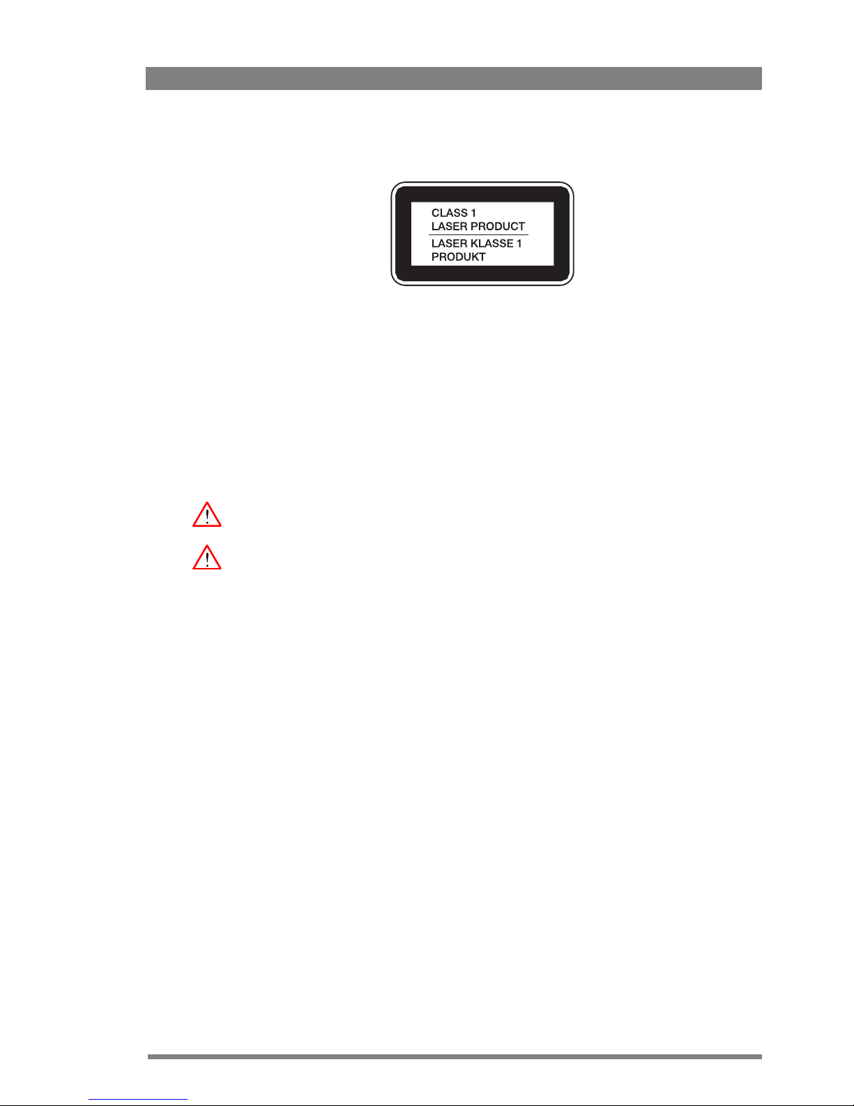
Fiber-optic transmission units are classified as a “CLASS 1 Laser Product” according to
EN
60825-1, Safety of Laser products. Class 1 laser products are considered safe and do not
result in biological hazard if used according to the instructions.
Laser safety statement (US)
Fiber-optic transmission units are classified as a “CLASS 1 Laser Product” according to
21CFR
1040.10 of the US Food and Drug Administration (FDA) Center for Devices and
Radiological Health.
Use of controls, adjustments or performance of procedures other than those specified herein
may result in hazardous radiation exposure.
To ensure proper use of this product, please read this instruction manual carefully and retain
for future reference. Should the unit ever require maintenance, contact an authorized service
location.
Fiber-optic cable precautions
Fiber-optic cables and connectors are easily damaged; take the following percautions into
account:
– Do not bend the cable beyond the minimum permissible bend range specified for the
cable.
– Avoid kinks in the cable.
– Avoid subjecting the cable to a high tension force (even momentarily).
– Do not twist the cable when connecting it to equipment.
– Insert connectors straight and fully into their corresponding sockets.
– In fiber-optic cable systems always put the dust caps on cable and panel connectors
immediately after disconnecting a cable. Keep the dust caps clean.
Page 8

8 XCU eXchangeable Control Unit User’s Guide (v1.6)
Cleaning fiber-optic connectors
WARNING
Never clean an optical connector attached to a fiber that is carrying light.
Particles of foreign matter on the tip of a ferrule can have a disabling effect on fiber-optic
transmission. Fiber-optic connectors need to be cleaned every time they are mated and
unmated; it is essential that fiber-optic users develop the necessary discipline to always clean
the connectors before they are mated.
Use a commerially available cleaning kit specifically designed for fiber-optic connectors and
follow the manufacturer's instructions carefully.
• The connector sections to be cleaned include the tips and sides of ferrules, the interior
walls of alignment sleeves, and the interior and exterior of connector shells.
• For plugs, the interior surfaces of alignment sleeves and the tips of ferrules are to be
cleaned with a cleaning stick treated with the appropriate fluid. (Cleaning sticks with a
slender design are available that allow alignment sleeves to be cleaned without having to
detach them.)
• For jacks, it is important to clean both the tips and sides of the completely protruding
ferrules.
• Both the male and female connector shells tend to attract dust and metal particles, so it is
important to clean both the insides and outsides.
• The fiber end face and ferrule must be absolutely clean before it is inserted into a
transmitter or receiver.
• Mate the connector immediately! Do not let the connector lie around and collect dust
before mating.
• Air can be used to remove lint or loose dust from the port of a transmitter or receiver to be
mated with the connector. Never insert any liquid into the ports.
Page 9

XCU eXchangeable Control Unit User’s Guide (v1.6) 9
Mains lead wiring for UK users
The wires in the mains lead are colored in accordance with the following code:
GREEN and YELLOW- EARTH
BLUE- NEUTRAL
BROWN- LIVE
As the colors of the wires in the mains lead of this apparatus may not correspond with the
colored markings identifying the terminals in your plug proceed as follows:
• The wire colored GREEN AND YELLOW must be connected to the terminal on the plug
marked with the letter E or by the safety earth symbol
or colored GREEN or GREEN
AND YELLOW.
• The wire colored BROWN must be connected to the terminal marked with the letter L or
colored RED.
• The wire colored BLUE must be connected to the terminal marked with the letter N or
colored BLACK.
Ensure that your equipment is connected correctly - if you are in any doubt consult a qualified
electrician.
Page 10

10 XCU eXchangeable Control Unit User’s Guide (v1.6)
Page 11

XCU eXchangeable Control Unit User’s Guide (v1.6) 11
Chapter 1 - Introduction
Chapter 1
Introduction
1.1 Welcome
Grass Valley’s XCU (eXchangeable Control Unit) is a heavy duty, multi-standard transmission
and power system designed for Grass Valley studio cameras.
1.1.1 About this manual
The purpose of this manual is to present a detailed description of how to install and operate
the XCU . It provides the information necessary to install, set up and operate the unit in
different configurations.
1.1.2 Related documents
Before proceeding, check the Grass valley website at www.grassvalley.com for the latest
version of this user’s guide and additional information:
• Online versions of documentation; updated versions of user’s guides, data sheets,
brochures, application notes in pdf-format are available for download.
• Software downloads; camera software updates, release notes and installation instructions
are available for download.
Page 12
12 XCU eXchangeable Control Unit User’s Guide (v1.6)
Chapter 1 - Introduction
1.2 Technology
1.2.1 Unique Cradle concept
The eXchangeable Control Unit system is like no other in the world. Its unique cradle can be
pre-mounted and pre-wired in a 19-inch rack, making a secure mechanical and electrical
connection, permitting the XCU box to easily slide in and out whenever needed. Each XCU
comes with one cradle, but additional cradles may be acquired to extend usability across
different environments, allowing you to quickly and easily transfer XCUs between OB vans,
studios, or anyplace.
The cradle concept allows for moving boxes easily and quickly between locations such as
trucks and studios. Pre-mounted and pre-wired to eliminate cabling errors, the unique cradle
provides on-demand resources for fast paced productions, resulting in less set up time and
more on-air time. Compatibility with the LDX Series and many LDK Series cameras extends
the cradle's usefulness across all types of productions.
Triax and/or Fiber connectors can easily be exchanged during production and in the field. All
other connectors are mounted on a separate connector panel in the cradle. After disconnecting
mains power and the Triax/Fiber transmission the box can be removed.
Page 13

XCU eXchangeable Control Unit User’s Guide (v1.6) 13
Chapter 1 - Introduction
1.2.2 3G Transmission
Grass Valley’s latest XCU is based on full digital transmission and a proven and robust power
system. The 3G transmission system consists of a dockable camera adapter that fits on Grass
Valley HD camera heads and an XCU that takes care of power, signal transport and conversion
and connection to the studio or OB van.
A wide range of 3G transmission versions is available, so there is always an option that suits
your operational situation best.
XCU 3G Triax
The XCU 3G Triax makes camera transmission fully compatible with industry standard Triax
cables. This allows the use of existing, reliable and valuable cable inventories and at the same
time increases already long cable runs with up to 25% greater distances.
3G Triax offers video transmission and remote control of cameras up to a distance of 1,500 m
(5,000 ft) and beyond, using standard 14 mm (0.55 in.) Triax cables.
XCU 3G Fiber
The XCU 3G Fiber is equipped with a hybrid fiber connector.
3G Fiber offers video transmission and remote control of cameras up to a distance of 3,000 m
(10,000 ft) and beyond, using hybrid fiber cables.
XCU 3G Dual
The XCU 3G Dual combines a Triax connector with a hybrid fiber connector.
XCU 3G Twin
The XCU 3G Twin combines a Triax connector with two dark fiber connectors.
1.2.3 XCU models
There are two XCU models available:
Elite
This model supports 720p/1080i/1080PsF video modes and offers 8x 1.5 Gbit/s HD-SDI video
outputs.
Connect the following cameras:
• LDX Series (720p, 1080i and 1080psf video modes only) and LDX 86 HS/XS (single speed
only)
• LDK 8000, LDK 8000 Elite and LDK 8300 (single speed only)
WorldCam
This model supports 720p/1080i/1080p/1080PsF video modes and offers 6x 3 Gbit/s, 2x
1.5 Gbit/s or 8x 1.5 Gbit/s HD-SDI video outputs.
Connect the following cameras:
• LDX Series (all video modes) and LDX 86 HS/XS (single speed only)
• LDK 8000, LDK 8000 Elite and LDK 8300 (single speed only)
Page 14

14 XCU eXchangeable Control Unit User’s Guide (v1.6)
Chapter 1 - Introduction
1.2.4 Camera control and monitoring
You can access the XCU menu, which contains all operational settings, from an Operational
Control Panel. In addition to the operational menu, the installation and service menus can be
accessed directly from the XCU. The XCU is compatible with all existing control system
components.
An OCP 400 operational control panel can be connected directly to the XCU using a cross-over
Ethernet cable. Full camera control is provided via a C2IP Ethernet-based control network.
The communication facilities provide for two-wire or four-wire high quality intercom signals.
Transmission quality can be continuously monitored before and during operation from the
OCP
400 operational control panel and/or the Connect Gateway.
Page 15

XCU eXchangeable Control Unit User’s Guide (v1.6) 15
Chapter 1 - Introduction
1.3 Main features
• Flexible and multiple audio and video connectivity.
• Unique cradle mounting concept ensures maximum flexibility at a minimum set-up time.
• Many different video transmission systems are available.
• Reliable video transmission of many video formats:
– 1080p50 and 1080p59.94 (XCU WorldCam versions only)
– 1080i50 and 1080i/59.94
– 720p50 and 720p59.94
– and many psf HD video formats.
• Transports the following digital signals from camera to XCU: main video signal, four audio
channels (including embedded digital audio), two intercom channels, control and private
data.
• Transports the following digital signals from XCU to camera: power, three external HD
video inputs, teleprompter signal, three intercom channels, control and private data.
• Full camera control via Grass Valley’s C2IP Ethernet-based control network.
• Three channel (two-wire or four-wire) intercom system compatible with international
standards.
• Built in a compact 2U high, 19-inch rack housing.
• Teleprompter, color bar, HD-SDI outputs standard on board.
• The digital transmission backbone and power module meet the most demanding
broadcasting needs.
• Heavy-duty design with a new reliable power unit with low power consumption, ideal for
outside broadcast vans.
• HD and simultaneous high-quality SD outputs available.
Page 16

16 XCU eXchangeable Control Unit User’s Guide (v1.6)
Chapter 1 - Introduction
Page 17
XCU eXchangeable Control Unit User’s Guide (v1.6) 17
Chapter 2 - Installation
Chapter 2
Installation
2.1 Rack installation
2.1.1 Installing rack mounting rails
The XCU Cradle can be mounted in most standard 19-inch video or IT rack types. The unit
needs two rack units (2 RU) of vertical space in the rack.
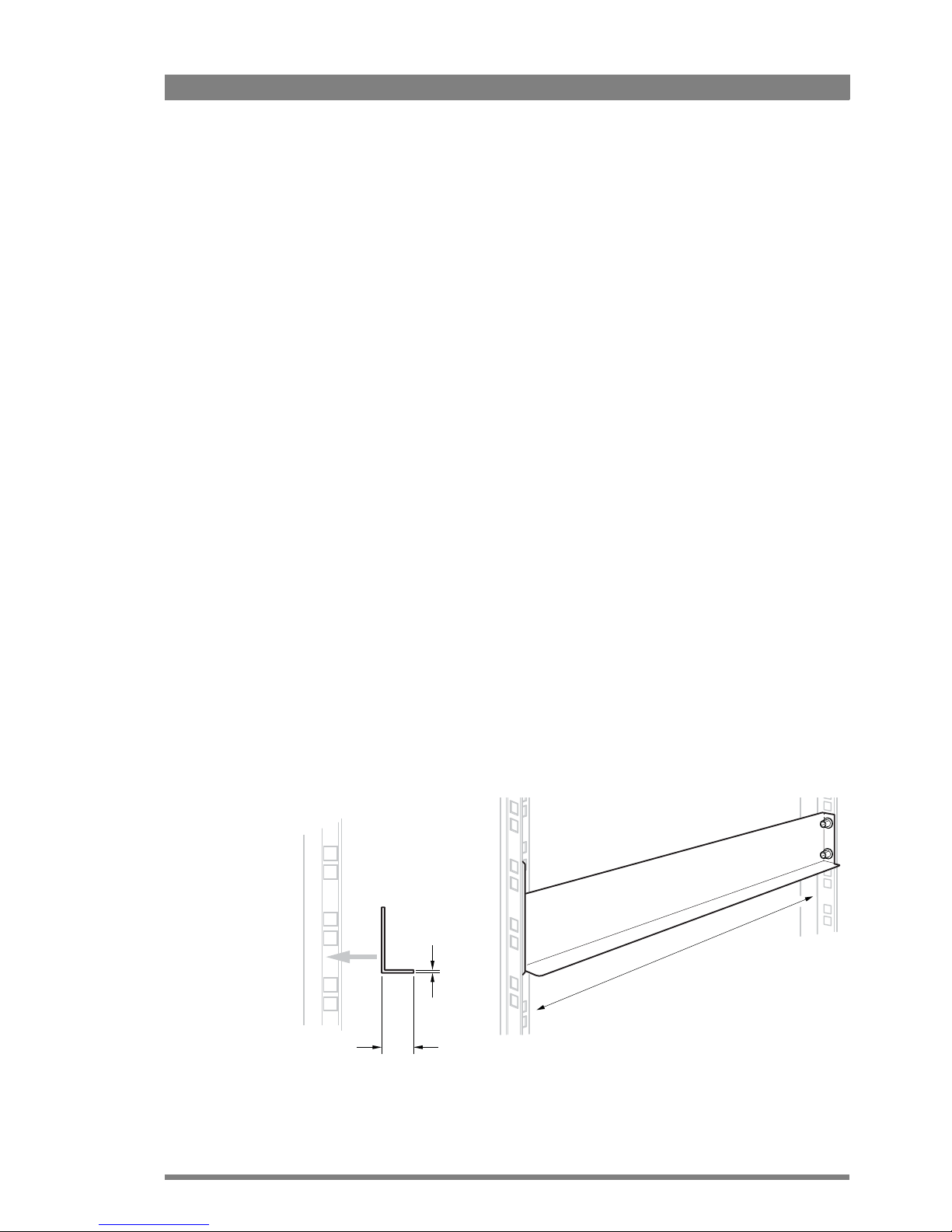
Install two L-shaped rack mounting rails (not supplied) that match your rack type. Refer to the
documentation of your mounting rails or rack for installation instructions.
• Make sure that both front and back end of the rails are attached to the rack. Allow a
minimum distance of 30 cm (11.8 in.) between the secured points.
• There should be a blind/untapped area in the front of the vertical rack beam where the
locking mechanism of the XCU engages the rack.
• The thickness of the horizontal leg of the L-shaped mounting rails must not exceed 2 mm
(0.08
in.) in order to leave enough space for more cradles to be mounted below the unit.
Below is an example of a rack mounting rail installed in a 19-inch rack. Note that your specific
situation may be different.
min. 30 cm (11.8 in.)
min. 12 mm (0.5 in.)
max. 2 mm (0.08 in.)
Page 18
18 XCU eXchangeable Control Unit User’s Guide (v1.6)
Chapter 2 - Installation
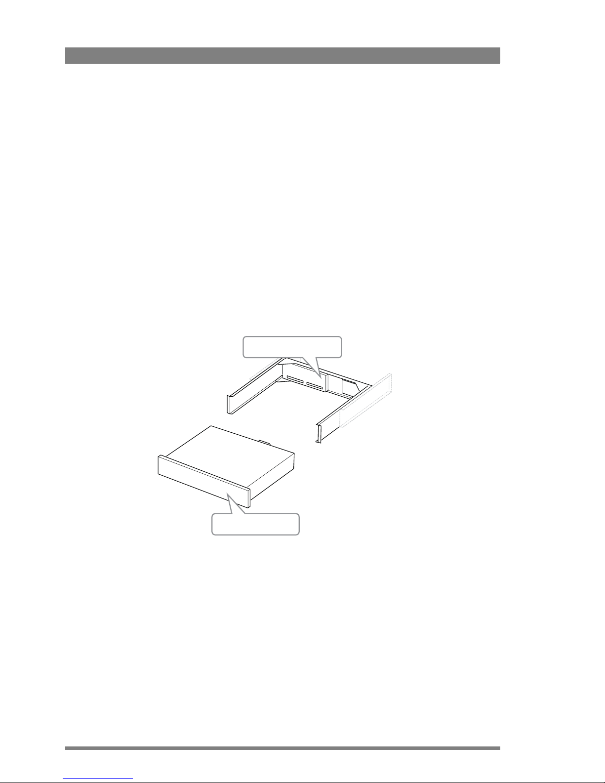
2.1.2 Installing the cradle
After mounting the rack mounting rails, install the cradle:
1. Slide the cradle into the rack so it is supported by the L-shaped mounting rails.
2. Fix the cradle to the front rack posts using four M6-screws (not supplied with the unit).
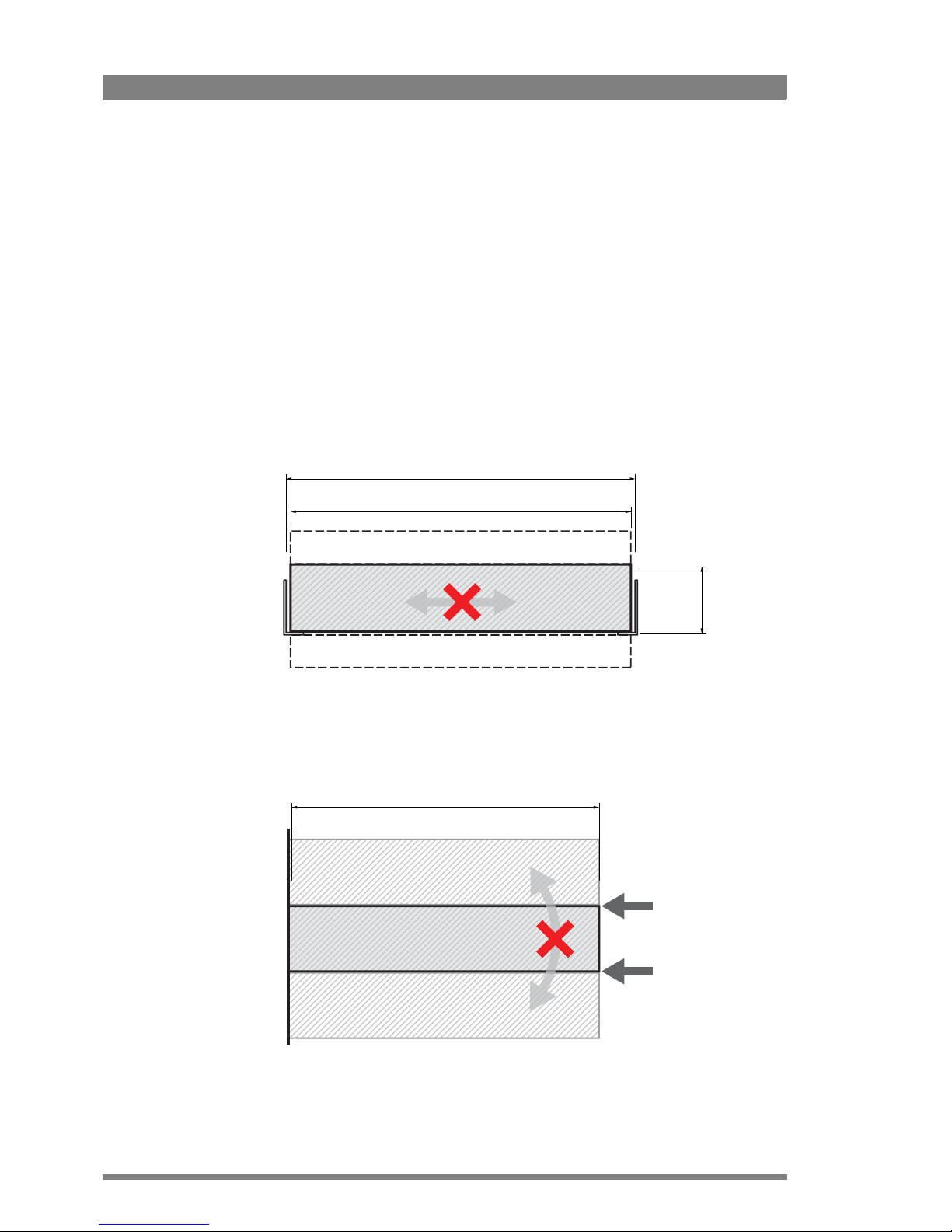
2.1.3 Transporting rack mounted XCUs
When transporting rack mounted XCUs in a flightcase make sure to take the following
precautions:
• Use proper shock absorbers for the rack to prevent damage during transport.
• To prevent any horizontal movement of the cradle and XCU during transport, make sure
there is as little horizontal clearance as possible between the cradle and the mounting
rails:
• To prevent any vertical movement of the cradle during transport, lock up the cradle
between other units and the vertical rail stands as indicated in the illustration below. Make
sure there is enough support at the back of the unit, at a minimum distance of 400 mm
from the rack front/
438 mm
450 mm — 455 mm
88 mm (2 RU)
XCU
(free space)
(free space)
400 mm
FRONT XCU
XCU or other rack device
XCU or other rack device
Page 19
XCU eXchangeable Control Unit User’s Guide (v1.6) 19
Chapter 2 - Installation
2.1.4 Connecting studio cabling
The studio cabling (main video outputs, control and intercom connections, studio signalling)
can now be connected according to your application and studio configuration. Refer to “Cradle
back panel” on page 50 for connectors and signals available on the cradle.
More information about studio signalling, control network, intercom cabling and other studio
infrastructure can be found further down this chapter.
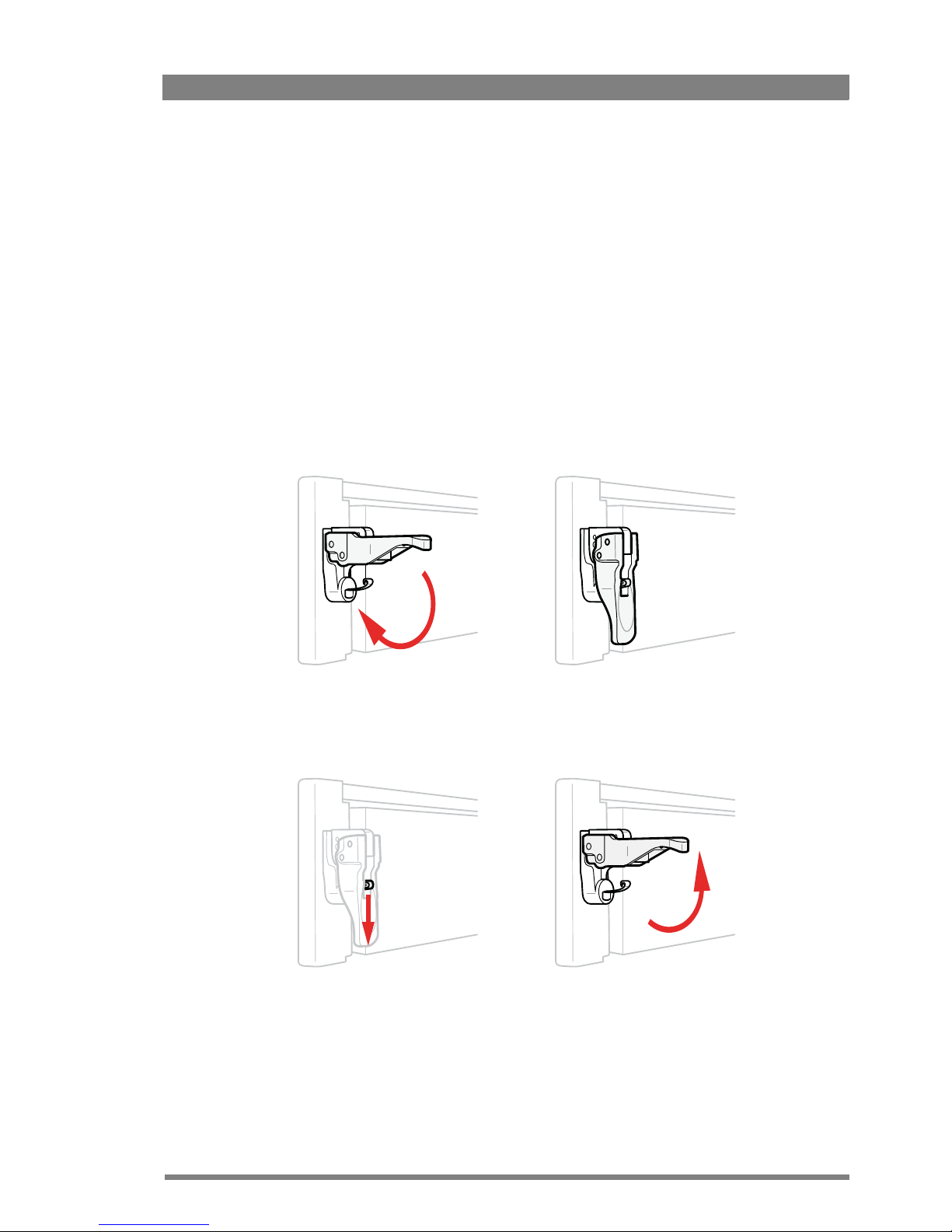
2.2 Mounting the XCU
To mount the XCU into the cradle, proceed as follows:
• Place the XCU onto the sliding rails of the cradle, slide the unit into the cradle and push
firmly.
• Push down the right and left locking handles until they snap down.
To remove the XCU from the cradle, proceed as follows:
• Hold down the springs inside the locking handles and at the same time swing them open.
• Pull out the XCU from the cradle by pulling the XCU at its sides.
• Now the transmission and mains cables can be connected. Refer to “XCU back panel” on
page 49 for connectors and signals available on the XCU.
Page 20

20 XCU eXchangeable Control Unit User’s Guide (v1.6)
Chapter 2 - Installation
2.3 Setting up the control network
The XCU is connected to the control network hub or router via an Ethernet cable (straightthrough, not cross-over) via the C2IP (RJ45) connector. An OCP 400 (Operational Control Panel)
and, if required an MCP 450 (Master Control PC), are also connected to the Ethernet network
via a hub or router. An OCP 400 can also be connected directly to the XCU using a (cross-over
or a straight-through) Ethernet cable.
The IP address and other options for the Ethernet connection can be set up in the XCU menu.
☞
Note
☞
Note
By default, the Ethernet connection is set up for Auto IP configuration.
2.4 Setting up intercom
Connect the studio intercom system to the rear of the XCU. Both a two and four-wire cabling
can be used. In the
AUDIO/INTERCOM > INTERCOM > ENG > WIRE MODE menu select the
cabling system: 2wire or 4wire.
The wiring of the panel connector is shown below for two-wire and four-wire systems.
2.4.1 Two-wire systems
2.4.2 Four-wire systems
Signal Value
Signal level 0 dBu (RMS)
Load impedance 200
Voltage level max. 40 VDC
8
1
15
9
Housing
Prod
Housing
Eng in/out
Prod in/out
Signal Value
Output signal level +6 or 0 dBu (RMS) selectable
Output impedance max. 50 symmetrical
Input signal level +6 or 0 dBu (RMS) selectable
Impedance min. 9 k symmetrical
8
1
15
9
Housing
Eng in/out
Prod in/out
Housing
Prog in ret
Prog in
Prod in ret
Prod in
Eng in ret
Eng in
Page 21

XCU eXchangeable Control Unit User’s Guide (v1.6) 21
Chapter 2 - Installation
2.5 Setting up studio signalling
Connect the studio signalling system to the rear of the XCU. The wiring of the signalling
connector is shown below:
There are several connection methods for the ISO (On Air Yellow), On Air and Call signalling
functions: dry contact, common ground, voltage level and open circuit/voltage level.
A selection in the INSTALL > SIGNALLING INPUT menu allows you to make the activity state
of the function (Active or Inactive) correspond to a particular input signal. There are two leads
for each connection - Send and Return.
2.5.1 Dry contact
☞
Note
☞
Note
A common return (not ground!) can be used for all three functions (ISO, On Air and Call)
If a contact is closed, the corresponding function is Active or Inactive, depending on the
selection in the INSTALL > SIGNALLING INPUT menu:
1
8
9
15
Call out send
Prev.out send
Prev.out ret.
ISO in send
ISO in return
Call in send
Call in return
5 V
Housing
Call out return
On Air send
On Air return
Audio 1 level
Audio 2 level
GND
Signal Send pin Return pin
ISO 3 11
On Air 4 12
Call 2 10
ISO 1a
ISO 1b
On-Air (Tally) 1a
On-Air (Tally) 1b
Call 1a
Call 1b
ISO in ext. send (pin 3)
ISO in ext. return (pin 11)
On-Air in ext. (pin 4)
On-Air in ext. return (pin 12)
Call in ext. (pin 5)
Call in ext. return (pin 13)
External ISO signalling
(dry contact)
External On-Air signalling
(dry contact)
External Call signalling
(dry contact)
Page 22

22 XCU eXchangeable Control Unit User’s Guide (v1.6)
Chapter 2 - Installation
2.5.2 Dry contact with multiple XCUs
This is an example of an On Air signalling with multiple XCUs using a common contact.
☞
Note
☞
Note
Use either Send or Return only, but do not mix.
If a contact is closed, the corresponding function is Active or Inactive, depending on the
selection in the INSTALL > SIGNALLING INPUT menu:
Menu setting Input is shorted: Input is open:
LH (low-high) Function is Active Function is Inactive
HL (high-low) Function is Inactive Function is Active
On-Air (Tally) 1
On-Air (Tally) 2
On-Air (Tally) n
Common
External On-Air signalling
(common contact)
On-Air in ext. send (pin 4) Signalling connector
On-Air in ext. return (pin 12) Base Station 1
Signalling connector
Base Station 2
Signalling connector
Base Station n
On-Air in ext. send (pin 4)
On-Air in ext. return (pin 12)
On-Air in ext. send (pin 4)
On-Air in ext. return (pin 12)
Menu setting Input is shorted: Input is open:
LH (low-high) Function is Active Function is Inactive
HL (high-low) Function is Inactive Function is Active
Page 23

XCU eXchangeable Control Unit User’s Guide (v1.6) 23
Chapter 2 - Installation
2.5.3 Common ground
☞
Note
☞
Note
Ensure that a reliable ground coupling exists between the control device ground and the XCU
ground.
If a contact is closed, the corresponding function is Active or Inactive, depending on the
selection in the INSTALL > SIGNALLING INPUT menu:
On-Air (Tally) 1
On-Air (Tally) 2
On-Air (Tally) n
External On-Air signalling
(common ground contact)
On-Air in ext. (pin 4) Signalling connector
On-Air in ext. return (pin 12) Base Station 1
Signalling connector
Base Station 2
Signalling connector
Base Station n
On-Air in ext. (pin 4)
On-Air in ext. return (pin 12)
On-Air in ext. (pin 4)
On-Air in ext. return (pin 12)
Menu setting Input is shorted: Input is open:
LH (low-high) Function is Active Function is Inactive
HL (high-low) Function is Inactive Function is Active
Page 24

24 XCU eXchangeable Control Unit User’s Guide (v1.6)
Chapter 2 - Installation
2.5.4 Voltage level
Apply a DC voltage to the inputs (respect polarity). If the voltage is low (0 to 2.5 V), the function
is Active (or Inactive). If the voltage is high (4 to 24 V) the function is Inactive (or Active). The
function state depends on the selection in the INSTALL > SIGNALLING INPUT menu:
2.5.5 Open circuit/Voltage level
Leave the circuit open or apply a DC voltage to the inputs (respect polarity). If the circuit is
open, the function is Active (or Inactive). If the voltage is high (4 to 24 V) the function is Inactive
Menu setting Input is 0 to 2.5V: Input is 4 to 24V:
LH (low-high) Function is Active Function is Inactive
HL (high-low) Function is Inactive Function is Active
ISO 1a
0 .. 2.5 V
DC
4 .. 24 V
DC
0 .. 2.5 V
DC
4 .. 24 V
DC
0 .. 2.5 V
DC
4 .. 24 V
DC
ISO 1b
On-Air (Tally) 1a
On-Air (Tally) 1b
Call 1a
Call 1b
ISO in ext. send (pin 3)
ISO in ext. return (pin 11)
On-Air in ext. send (pin 4)
On-Air in ext. return (pin 12)
Call in ext. send (pin 5)
Call in ext. return (pin 13)
+
-
+
-
+
-
ISO 1a
Open/
4..24 V
DC
Open/
4..24 V
DC
Open/
4..24 V
DC
ISO 1b
On-Air (Tally) 1a
On-Air (Tally) 1b
Call 1a
Call 1b
ISO in ext. send (pin 3)
ISO in ext. return (pin 11)
On-Air in ext. send (pin 4)
On-Air in ext. return (pin 12)
Call in ext. send (pin 5)
Call in ext. return (pin 13)
Page 25

XCU eXchangeable Control Unit User’s Guide (v1.6) 25
Chapter 2 - Installation
(or Active).
The function state depends on the selection in the INSTALL > SIGNALLING INPUT menu:
2.6 Setting up external audio level
The camera audio levels for channel 1 and 2 can be externally controlled by the XCU. In the
camera system menu, go to the INSTALL
> AUDIO > AUDIO GAIN MODE item and select Ext.
On the OCP 400, push the SETUP button and choose the Cam submenu. Use the NEXT
button to scroll to the REM AUDIO menu and select Rem. Apply a DC voltage to pins 6 and 14
of the signalling connector to control the levels of audio channels 1 and 2 respectively, as
shown in the figure below:
The actual audio level depends on the setting of the switches at the back panel of the camera
adapter. When Mic is selected, the max. gain level is -64 dBu, while max. line level is -32 dBu.
Menu setting Input is open: Input is 4 to 24V:
OH (open-high) Function is Active Function is Inactive
HO (high-open) Function is Inactive Function is Active
Audio 1 level (pin 6)
Audio 2 level (pin 14)
Mic/Line
Mic/5 V (pin 7)
GND (pin 15)
1k
1k
1k
1k
1k
1k
1k
1k
+4.3V
+3.7V
+3.1V
+2.5V
+1.9V
+1.3V
+0.7V
0V
-22/+12dBu
-28/+4dBu
-34/-2dBu
-40/-8dBu
-46/-14dBu
-52/-20dBu
-58/-26dBu
-64/-32dBu
Page 26

26 XCU eXchangeable Control Unit User’s Guide (v1.6)
Chapter 2 - Installation
2.7 Using private data
Private data channels can be used for sending serial data via the transmission cable. For
example, electronic scriptboard or character data for a video display unit or pan and tilt data can
be transmitted to the camera.
☞
Note
☞
Note
Propagation-delay times vary with cable length, especially if a return signal is involved. At
max.lengths the total delay is at least 25 μs and can be more than 30 μs depending on the type
of cable. The duty cycle difference between input and output is max. 5%.
5
4
3
2
1
9
8
7
6
Private
data in
Private
data out
Function Value
Bitrate max. 100 kbit/s
Output level (high) > 4 V
Output level (low) < 4 V
Output impedance 250
Input level (high) > 2 V (max. 12 V)
Input level (low) < 2 V
Input impedance > 4.7 k
Page 27

XCU eXchangeable Control Unit User’s Guide (v1.6) 27
Chapter 3 - Setup
Chapter 3
Setup
3.1 Front navigation panel
The front navigation panel is used to set the camera number and to access and navigate the
internal XCU menu.
3.2 Setting the camera number
Hold the Select button [5] until the camera number on the display [1] starts flashing. Now use
the Up [3] and Down [4] buttons to select the camera number. Push Select again to confirm the
settings or push Back [2] to undo the selection.
3.3 Accessing the menu
3.3.1 Using the XCU front navigation panel
To access the internal XCU menu, push the Select [5] button. The display [1] shows “nn”.
Communication
Transmission
Camera Power
Cable
PowerOn Air
1 32
4 5
Display Back Up
SelectDown
Page 28

28 XCU eXchangeable Control Unit User’s Guide (v1.6)
Chapter 3 - Setup
3.3.2 Using the OCP 400 operation control panel
The OCP 400 can be used to access the XCU menu remotely:
1. Push the SETUP button on the OCP 400 to open the setup menu.
2. Push the Selection button to choose the BS menu.
3. Push the Selection button enter the menu,.
4. The menu appears on the Monitoring outputs of the XCU. Use the appropriate selection
buttons to navigate the menu. You can also use the rotary contol on the OCP
400 to move
up or down through the menu.
3.4 Navigating the menu
The XCU menu is used for configuring the unit. As there are a large number of functions and
set-up options available, it may require some time to become familiar with them all. The menu
is available on the Monitoring outputs.
3.4.1 Entering the menu
Use the navigation panel on the XCU or the OCP 400 to access the menu. The functions of the
XCU are grouped into menus and sub-menus. When accessed, the main menu appears on the
monitor outputs:
The main menu screen shows five items and the name of the menu (at the bottom). One or
more item can be hidden but become visible when you scroll down. A cursor shows your
position in the menu. Use the Up and Down buttons to move the cursor up and down.
TOGGLE
PREV NEXT
EXIT
BS
Diag
Cam
OCP
TOGGLE
PREV NEXT
EXIT
Menu
TOGGLE
PREV NEXT
EXIT
DOWNUPSELECT
Video
Monitoring
Audio/Intercom
Install
Security
Diagnostics
MENU OFF
Root
>>
>>
>>
>>
>>
>>
Page 29

XCU eXchangeable Control Unit User’s Guide (v1.6) 29
Chapter 3 - Setup
3.4.2 Finding your way
Use the navigation buttons to move the cursor through the menu items. If a double arrow (>>)
is visible, then pressing the Select button brings you one level lower in the menu system. Only
five items are visible in each menu. Scroll up or down to see more items.
When you first enter a menu (other than the main menu) the cursor is positioned next to the
first item. The TOP and PREVIOUS entries are not immediately visible but are located above
the first item. Use the control to scroll up to them.
• Select TOP to bring you back to the Main menu.
• Select PREVIOUS to go back to the menu that you were in before the current one.
The System menu above shows the items displayed when you first enter the menu and the
other items that are available by scrolling up or down.
3.4.3 Leaving the menu
If you are deep within the menu structure, follow these steps to leave:
• If necessary move the cursor to the left column.
• Scroll upwards until the cursor points to TOP (this is the main menu).
• Press the Select button; the cursor now points to the Menu Off item of the Main menu.
• Press the Select button to leave the menu.
This is the recommended way of leaving the system menu. The menu system disappears after
a few seconds when you stop navigating. This delay can be set in the MONITORING > MENU.
However, when you enter the menu again you enter at the last position of the cursor and not at
the top of main menu. To prevent confusion the next time you enter the system menu, it is
advisable to leave the system menu by returning to the main menu (TOP) and selecting MENU
OFF.
3.4.4 Making changes
To find out where to change a function, consult “XCU menu reference” on page 37 to find out
under which menu group or subgroup the function is located. If the cursor points to an item
(and there are no double arrows to indicate a sub-menu) then the item pointed to has a value.
The value can be:
Camera Number
IP Address
Ethernet
Serial
Camera Power
NoSignal
Video Mode
Teleprompter
TOP
PREVIOUS
System
1
>>
>>
>>
On
Col.Bar
720p59
Off
Page 30

30 XCU eXchangeable Control Unit User’s Guide (v1.6)
Chapter 3 - Setup
• a toggle value (only two values, for example Yes or No)
• a list value (more than two values)
• an analog value (variable from 00 to 99)
• or unavailable (---).
If the value is unavailable it cannot be changed. This is indicated by three dashes (---). This can
occur, for example, when a function is switched off. The analog values associated with that
function are then unavailable. If there are only two values associated with the function, then
pressing the Select button toggles between these two values. If a value is displayed next to a
function that is one of several possible values, then pressing the Select button places the
cursor in a list menu indicating the value currently selected. Use the Up and Down buttons to
point to a new value. Press the Select button to return the cursor to the function list. If an
analog value is displayed next to a function name, pressing the Select button places the cursor
in front of the value and the navigation control is used to change the analog value. Press the
Select button to return the cursor to the function list.
Using Recall File to undo changes
If you make changes to the settings in the menu and you decide not to keep them, use the
Recall File function to recall a standard or stored set of values for the parameters. These files
are available in the Files menu.
3.4.5 User levels
There are four user levels: user 0, user 1, user 2 and user 3. The purpose of the user levels is to
restrict the set of functions which can be changed by whoever is operating the unit. User level
0 is a special protection level which locks most of the operational controls of the camera. Use
this level to ensure that a camera that has been set-up is not tampered with. User level 0 is not
normally used for operational purposes as it is too restrictive for normal circumstances. The
recommended minimum user level is 1. For full control set the level to 3. When you switch off
the power, the access rights that were obtained by the use of the PIN code are disabled and
the camera starts at the assigned user level when switched on again.
Page 31

XCU eXchangeable Control Unit User’s Guide (v1.6) 31
Chapter 3 - Setup
3.5 Intercom setup
The studio camera systems offer extensive intercom facilities between cameraman, tracker
(floor man), XCU and studio. To help you set up and operate the intercom system, the following
controls are available:
• XCU menu system
• Camera head menu system
• Camera adapter rear panel
• Camera head switches
Tip
✎
When setting up a system it is usually more convenient to use an OCP 400 to set your
preferences in both the XCU and camera head menus.
3.5.1 Studio interface setup
A four-wire or a two-wire studio system can be connected to the XCU. In the AUDIO/
INTERCOM > INTERCOM menu, select the Wire Mode for the engineering (ENG), production
(PROD) and program (PROG) channels. By default these values are set to four-wire.
Isolate
The isolate function completely disconnects the XCU intercom from the studio system.
Levels
In the four-wire mode the menu gives you a choice of either a 0 dBu or a +6 dBu signal level. In
the two-wire mode this level is set to 0 dBu.
• Set the input and output intercom levels for the PROD and ENG channels. The range is 0
to 99; default is 50.
• Set the input level for the PROG channel.
• Set the levels for the sidetone in a two-wire system in this menu.
Page 32

32 XCU eXchangeable Control Unit User’s Guide (v1.6)
Chapter 3 - Setup
3.6 Color bars
For set up and test purposes, the XCU can generate a color bar signal at the HD-SDI output
connectors. This signal will be only present when no camera is connected and no valid video
signal is received.
• To turn on the XCU color bar, go to the VIDEO > COLOR BAR > COLOR BAR item and select
On.
• The color bar type can be selected with the VIDEO > COLOR BAR > COLOR BAR TYPE
item. Two color bar types are available: Split (default) and Full.
3.7 Timing
All main HD Video, SD and monitoring output signals coming from the XCU are in phase. Still,
due to different cable lengths or other delays, the signals from different XCUs can be out of
phase when they are connected to a video switcher or router.
This variation in phase can be compensated for in the XCU by using horizontal phase (H-phase)
adjustment. Go the INSTALL > TIMING menu and adjust the H-PHASE item.
☞
Note
☞
Note
The phase shift can be further adjusted in the INSTALL > TIMING > SHIFT menu. Use the
PIXELS and LINES items to shift the signals over one or more pixels and one or more lines,
respecively. The maximum shift is exactly one frame.
Page 33

XCU eXchangeable Control Unit User’s Guide (v1.6) 33
Chapter 4 - Operation
Chapter 4
Operation
4.1 Front panel indicators
During setup and operation, transmission can be monitored on the XCU front panel. A display
and several LED indicators provide information about important operational functions.
Camera number display
In normal operation the segment display shows the camera number of the camera connected
to the XCU. When the internal menu is accessed, the display shows “nn”.
Communication indicator
This green indicator lights when communication between the camera and XCU is established
and working correctly. A red indicator indicates a communication error.
Transmission indicator
This indicator lights when a working signal transmission is established between the camera
and XCU. In case of a Triax connection, this indicator lights green. A correct Fiber connection is
indicated by a blue light. A red light indicates a connection error.
Communication
Transmission
Camera Power
Cable
PowerOn Air
293 4 5
7 86
1
1
2
3
Page 34

34 XCU eXchangeable Control Unit User’s Guide (v1.6)
Chapter 4 - Operation
Camera Power indicator
A green light means that the connected camera is powered by the XCU and switched on. A
blinking green light indicates that a camera is connected but not switched on. A red light
indicates a power supply error (e.g. a power overload).
Cable indicator
This green indicator lights when a transmission cable is correctly connected between the
camera and XCU. A blinking red light indicates a missing or interrupted transmission cable. A
red light indicates that a cable is connected but there is an error (e.g. a short circuit).
On Air indicator
The On Air indicator lights (red) when the connected camera is switched On Air.
On Air Yellow indicator (or ISO)
The On Air Yellow indicator lights when the connected camera is switched to On Air Yellow or
when the camera is in ISO mode.
On Air Green indicator (or Call)
The On Air Green indicator lights when the connected camera is switched to On Air Green or
when a Call signal is sent or received.
Power indicator
This green indicator lights when the XCU is switched on. A blinking green indicator means that
the unit is shutting down.
4.2 Transmission diagnostics on the OCP 400
With an Operational Control Panel (OCP 400) is connected to the system, transmission can be
monitored in the diagnostics page of the panel:
4
5
6
7
8
9
Indication Description
Cable or signal quality is OK.
Cable or signal quality is below optimum, transmission is still in operation. The
quality level can vary between 6 (high) and 0 (low) units.
TOGGLE
PREV NEXT
EXIT
Signal NoSignal
FibB Cable ERROR
Signal
FibA Cable
|
OK
Signal quality from XCU to
camera
Sgnal quality from camera to
XCU.
Cable quality from camera to
XCU.
Cable quality from XCU to
camera
OK
|
Page 35

XCU eXchangeable Control Unit User’s Guide (v1.6) 35
Chapter 4 - Operation
4.3 Replacement of fuses
Caution
Switch off the XCU and disconnect power cables before proceeding.
Use only fuses of the type and rating specified. Always replace both fuses at the same time.
The XCU is equipped with 2x T8AH type 250 V fuses . They are located in the mains entry at
the back of the unit. Follow these steps to replace the fuses located in the mains entry:
1. Insert a very small screwdriver into the hole at the left side and then at the right side of
the fuseholder to unclip both side of the fuseholder.
2. Extract the fuseholder from the mains entry by pulling of the small clip at the bottom of
the fuseholder.
3. Replace both fuses.
4. Insert the fuseholder until it clicks into place.
5. Connect the power supply for the XCU to the IEC connector at the rear.
Cable or signal quality is poor. Check cable and connectors for interruptions, broken
or dirty optical connections.
Cable error. Check cable and connectors for interruptions, broken or dirty optical
connections.
No signal is received. Check cable and connectors for interruptions, broken or dirty
optical connections.
Indication Description
|
ERROR
NoSignal
Insert small flat
screwdriver here
to open clip
Insert small flat
screwdriver here
to open clip
Page 36

36 XCU eXchangeable Control Unit User’s Guide (v1.6)
Chapter 4 - Operation
Page 37

XCU eXchangeable Control Unit User’s Guide (v1.6) 37
Chapter 5 - XCU menu reference
Chapter 5
XCU menu reference
5.1 Video menu
Menu item Settings Default Level Stored Description
Colour Bar
Colour Bar Off, On Off User 1 — Turns color bar on or off (when camera signal is
not present)
Bar Type Split, Full Split User 1 Cradle Selects color bar type.
SD Detail
Detail Off, On Off User 1 XCU Turns SD Detail on or off
Source R, G, Y, R+G Y User 1 XCU Selects the source for SD Detail signal
generation.
Level 0..99 25 User 1 XCU Sets overall SD Detail level: amount of detail
added to the SD video signal.
Vertical Lvl 0..99 50 User 1 XCU Sets the level of the vertical component in
the SD Detail signal.
Noise Slicer 0..99 10 User 1 XCU Sets the level of the Noise Slicer.
Coarse/Fine 0..99 90 User 1 XCU Sets SD Detail balance between coarse and fine
structures (0 = coarse, 99 = fine).
Level Dependence 0..99 30 User 1 XCU Sets the SD Detail reduction level for shadow
areas.
Soft Detail Off, On Off User 1 XCU Switches SD Soft Detail on or off. This function
reduces the amount of detail added fo large
transitions.
Soft Detail Lvl 0..99 50 User 1 XCU Sets the maximum limit level of detail for
Soft Detail.
Page 38

38 XCU eXchangeable Control Unit User’s Guide (v1.6)
Chapter 5 - XCU menu reference
5.2 Monitoring menu
5.3 Audio/Intercom menu
Menu item Settings Default Level Stored Description
Display On, Time Time User 2 XCU Selects the camera menu to be permanently On
or to disappear after a set Time.
Menu time 3..30 10 User 3 XCU Sets the length of time the menu is dis-played
when the Display mode is set to Time.
Statusbar
Camera Number Off, On Off User 1 — Switch on to show the camera number in the
status bar.
Name Off, Alias, Dev ID,
Head ID
Off User 1 — Switch on and select Alias, device ID (of the
XCU) or Head ID (of the connected camera) to
be shown in the status bar.
Cable Info Off, On Off User 1 — Switch on to show transmission cable
information in the status bar.
Menu item Settings Default Level Stored Description
Audio
Audio 1 Level 0dB, 6dB 6dB User 1 — Selects studio audio attenuation level for Audio
input 1.
Audio 2 Level 0dB, 6dB 6dB User 1 — Selects studio audio attenuation level for Audio
input 2
Intercom
Isolate
Isolate Isolate, System System User 1 Cradle Isolate = Isolate Program and Production
intercom from camera head;
System = isolate is off
Eng
Wire Mode 4wire, 2wire 4wire User 1 Cradle Selects wiring mode for the Engineering
intercom channel.
Volt/Cur drive 4wire, 2wire 4wire Service — Selects voltage of current drive mode.
2/4 wire 4wire, 2wire 4wire Service — Selects 2 or 4 wire intercom mode.
Level 0dB, 6dB 6dB User 1 XCU Selects intercom channel attenuation.
Side Tone 0..99 50 User 1 Cradle Sets side tone (feedback) volume level.
Prod
Wire Mode 4wire, 2wire 4wire User 1 Cradle Selects wiring mode for the Production
intercom channel.
Volt/Cur drive 4wire, 2wire 4wire Service — Selects voltage of current drive mode.
2/4 wire 4wire, 2wire 4wire Service — Selects 2 or 4 wire intercom mode.
Level 0dB, 6dB 6dB User 1 XCU Selects intercom channel attenuation.
Side Tone 0..99 50 User 1 Cradle Sets side tone (feedback) volume level.
Prog
Page 39

XCU eXchangeable Control Unit User’s Guide (v1.6) 39
Chapter 5 - XCU menu reference
5.4 Install menu
Wire Mode 4wire, 2wire 4wire User 1 Cradle Selects wiring mode for Program intercom
channel.
Level 0dB, 6dB 6dB User 1 XCU Selects intercom channel attenuation.
Menu item Settings Default Level Stored Description
Menu item Settings Default Level Stored Description
Camera Number 1..99 1 User 2 Cradle Sets logical camera number (preferred method
to set this is via the front panel).
Alias <text> — User 2 XCU Sets Alias for the camera system.
Device ID <text> — User 2 Cradle Sets Device ID for the XCU.
Timing
H Phase 0..99 50 User 0 Cradle Sets the horizontal (H) synchronization phase.
Shift
Pixels 0..1920 0 Service Cradle Selects output time shift for all video outputs in
pixels.
Lines 0..1080 0 Service Cradle Selects output time shift for all video outputs in
video lines.
Time/Date
Time <Time> User 2 — Shows current time.
Date <Date> User 2 — Shows current date.
Change Time
Hours (24h) 0..23 0 User 2 — Sets the value for hours.
Minutes 0..59 0 User 2 — Sets the value for minutes.
Set time Exec, .. User 2 — Apply new time settings.
Change Date
Day 1..31 1 User 2 — Sets the value for day.
Month 1..12 1 User 2 — Sets the value for month.
Year 2000...2199 2012 User 2 — Sets the value for year.
Set date Exec, .. User 2 — Apply new date settings.
Status NotSet, DataLoss,
Error, Ok
Ok User 2 — Shows the time/date setting status.
Batt. Status Ok, Low, Error Ok User 2 — Show Battery Status. When low, have the
internal battery replaced.
Signalling input
Onair Source GPIO, Ethernet GPIO User 0 Cradle GPIO (General Purpose Input/Output): On Air is
controlled by the signalling connector on the
XCU;
Ethernet: On Air is controlled via the C2IP
(Ethernet) network, e.g. by the OCP 400.
Onair R Inp. Low/High, High/
Low, Open/High,
High/Open
Low/
High
User 0 Cradle Selects switch mode for the Red On Air
signalling input.
Page 40

40 XCU eXchangeable Control Unit User’s Guide (v1.6)
Chapter 5 - XCU menu reference
Onair Y Inp. Low/High, High/
Low, Open/High,
High/Open
Low/
High
User 0 Cradle Selects switch mode for the Yellow On Air (ISO)
signalling input.
Call Input Low/High, High/
Low, Open/High,
High/Open
Low/
High
User 0 Cradle Selects switch mode for the Call signalling input.
Signalling Outp.
Crash2Air On, Off Off Service XCU (special purpose)
Network
IP mode Auto, Manual Auto User 0 — Selects manual or automatic IP configuration
mode.
Subnet Mask 0..31 0 User 0 — Sets the subnet mask value (when manual IP
mode is selected).
BS IP digit 1 1..250 0 User 0 Cradle
Sets XCU IP address (when IP mode is manual).
BS IP digit 2 0..255 0 User 0 Cradle
BS IP digit 3 0..255 0 User 0 Cradle
BS IP digit 4 1..254 0 User 0 Cradle
CAM IP digit 1 1..250 0 User 0 Cradle
Sets camera head IP address (when IP mode is
manual).
CAM IP digit 2 0..255 0 User 0 Cradle
CAM IP digit 3 0..255 0 User 0 Cradle
CAM IP digit4 1..254 0 User 0 Cradle
Apply IP settings Exec, .... Exec User 0 — Select Exec to apply the new IP settings.
AFD
Insert On. Off Off Service XCU Turns AFD (Active Format Description)
embedding in video signal on or off.
Setting 16:9 (Full), 4:3
(Center)
16:9
(Full)
User 3 — Selects type of AFD (Active Format
Description) code to be embedded in the
video signal.
Extern Video
Aspect Ratio 16:9, 4:3 16:9 User 3 Cradle Selects aspect ratio for external video inputs.
No Signal Col.Bar, Black Col.Bar User 3 — Selects a color bar or a black frame signal is
output when no camera is connected
Video Mode 1080i50 ... — User 3 XCU Selects a video mode for the XCU test signal
when no camera is connected.
3G Output Level A, Level B Level A User 3 XCU Selects SMPTE 425M Level-A or Level-B
mapping to be used for the 3G video outputs.
HD-SDI Out D HD, SD HD User 3 XCU Selects video output signal (HD or SD) on video
connector D.
Out D Scaling 1080i, 720p 1080i User 3 XCU Selects scaler to use for output signal on video
connector D (when HD-SDI Out D = HD)
SD AspectRatio 16:9, 4:3 16:9 User 3 — Selects aspect ratio for SD outputs.
SD LetterBox Off, 16:9 Off User 3 — Selects letter box mode ratio for SD outputs.
HDSDI LensData Off, On Off Service Cradle Enable to embed lens data into HD-SDI signal.
Menu item Settings Default Level Stored Description
Page 41

XCU eXchangeable Control Unit User’s Guide (v1.6) 41
Chapter 5 - XCU menu reference
5.5 Security menu
5.6 Licenses menu
Menu item Settings Default Level File Description
Installed level User0 .. User3 User 0 Service — Selects XCU user level.
Note: switch the unit off and on to take the
changes into effect.
Cur. User Level No Oper, User0 ..
Serv1
User 0 Service — Selects current XCU user level.
PIN Code <code> — Service — Enter a PIN code to access Service level
Key
Type Unknown Unknown Service — (advanced settings)
Number 0 .. 1000 0 Service — (advanced settings)
Factory Defaults Exec, ... Exec Service — Resets all XCU settings to their factory
defaults.
Menu item Values Default Level File Description
Active Licenses
WorldCam Unknown, Not
Applicable, Not
Present,
Temporary,
Perpetual, Trial,
Clock Error
Unknown User 2 — Shows status of the WorldCam License,
when installed.
Time Left 0..65535 sec — User 2 — Shows time left in seconds for WorldCam
License.
New Licenses
Find Licenses
Search Next Exec, ... Exec User 2 — Execute to search the next license (if
existing) on the USB Flash Drive or internal
memory.
Add License Exec, ... Exec User 2 — Execute to add the found license.
Type None, WorldCam None User 2 — Shows the type of the found license
Status Unknown, Not
Applicable, Not
Present,
Temporary,
Perpetual, Trial,
Clock Error
Unknown
User 2 — Shows the status of the found license.
Trial License
Select Type None, WorldCam None User 2 — Selects License type to use for trial
licensing.
Activate Exec, ... Exec User 2 — Execute to make the selected trial license
active (trial licenses are active for 3
minutes).
Page 42

42 XCU eXchangeable Control Unit User’s Guide (v1.6)
Chapter 5 - XCU menu reference
5.7 Diagnostics menu
Time Left 0..179 sec — User 2 — Shows time left after activating a trial
license.
Menu item Values Default Level File Description
Menu item Values Default Level Stored Description
Cable Power
Camera Power On, Off On User 2 — (advanced settings)
Connector None, Fiber, Triax,
Error
None User 2 (advanced settings)
Status Unknown, Open,
Power Off,
Overload, Short,
Cam Off, Cam On,
Error
UnknownUser 2 — (advanced settings)
Int.Error Unknown, VMtest,
STtest, CStest,
FBtest, Start,
Shutdown,
nonFlex, Family
UnknownUser 2 — (advanced settings)
Communication
Cam Connected Yes, No No User 2 — (advanced settings)
C2IP Panels 0..99 0 User 2 — (advanced settings)
LDK Connect Gw Yes, No No User 2 — (advanced settings)
Ethernet
MAC-Address <####> — User 2 Cradle (advanced settings)
Link state Connected,
Disconn
Disconn User 2 — (advanced settings)
Link type Unknown, 10Mb/
Half, 10Mb/Full,
100Mb/Half,
100Mb/Full,
Negotiate
UnknownUser 2 — (advanced settings)
Loopback test
Loopback test Off, On Off Service — (advanced settings)
Data count <####> Service — (advanced settings)
Data errors 0..65535 0 Service — (advanced settings)
Data loss 0..65535 0 Service — (advanced settings)
Transmission
Transm. path T2F Conv, F2T
Conv, 3GTriax,
3GFiber, Unknown,
None
None User 0 — (advanced settings)
Transm. select
Priority Auto, Triax, Fiber Auto User 0 — (advanced settings)
Page 43

XCU eXchangeable Control Unit User’s Guide (v1.6) 43
Chapter 5 - XCU menu reference
Transmission Triax, Fiber Triax User 0 — (advanced settings)
Transm. profile
Selection Mode Auto, Manual Auto Service XCU (advanced settings)
Profile 3G Optimal, HD
Optimal, 3G Robot,
HD Robot
3G
Optimal
Service XCU (advanced settings)
Triax
Cable Length <####> — User 0 — (advanced settings)
Cable Status OK, Critic, Error,
NoSig, Unknown
NoSig User 0 — (advanced settings)
Rx Sig.Status OK, Critic, Error,
NoSig, Unknown
NoSig User 0 — (advanced settings)
Tx Sig.Status OK, Critic, Error,
NoSig, Unknown
NoSig User 0 — (advanced settings)
Fiber
Fib A (CAM->XCU)
Cable Status OK, Critic, Error,
NoSig, Unknown
NoSig User 0 — (advanced settings)
Signal Status OK, Critic, Error,
NoSig, Unknown
NoSig User 0 — (advanced settings)
RX Margin — — User 0 — (advanced settings)
CRC Error Count 0..65535 50 Service — (advanced settings)
Fib B (XCU->CAM)
Cable Status OK, Critic, Error,
NoSig, Unknown
NoSig User 0 — (advanced settings)
Signal Status OK, Critic, Error,
NoSig, Unknown
NoSig User 0 — (advanced settings)
RX Margin — — User 0 — (advanced settings)
CRC Error Count 0..65535 50 Service — (advanced settings)
T2F Converter (Triax to Fiber Converter)
Temperature Ok, Unknown,
Critic, Error
UnknownUser 0 — (advanced settings)
FPGA Temp <temp> — Service — (advanced settings)
Fan — — User 0 — (advanced settings)
Cable Power Unknown, Open,
Power Off,
Overload, Short,
Cam Off, Cam On,
Error
Error User 0 — (advanced settings)
Int.Error Unknown, VMtest,
STtest, CStest,
FBtest, Start,
Shutdown,
nonFlex, Family
UnknownUser 0 — (advanced settings)
Package Ok. Not Ok Not Ok User 0 (advanced settings)
Package 12NC 0..65535 0 User 0 (advanced settings)
Package Version 0..65535 0 User 0 (advanced settings)
Menu item Values Default Level Stored Description
Page 44

44 XCU eXchangeable Control Unit User’s Guide (v1.6)
Chapter 5 - XCU menu reference
F2T Converter (Fiber to Triax Converter)
Temperature Ok, Unknown,
Critic, Error
UnknownUser 0 — (advanced settings)
FPGA Temp <temp> — Service — (advanced settings)
Package Ok. Not Ok Not Ok User 0 (advanced settings)
Package 12NC 0..65535 0 User 0 (advanced settings)
Package Version 0..65535 0 User 0 (advanced settings)
Transm. Details
Triax
Triax Locked Yes, No No Service — (advanced settings)
->XCU
Cable Length 0..65535 135 Service — (advanced settings)
Total Quality 0..65535 255 Service — (advanced settings)
Cable Quality Good, Average,
Bad, Undef
Undef Service — (advanced settings)
Signal Quality Good, Average,
Bad, Undef
Undef Service — (advanced settings)
Avg MER Good, Average,
Bad, Undef
Undef Service — (advanced settings)
Max MER Good, Average,
Bad, Undef
Undef Service — (advanced settings)
EQ Taps Good, Average,
Bad, Undef
Undef Service — (advanced settings)
RS Error Good, Average,
Bad, Undef
Undef Service — (advanced settings)
Filter MER Good, Average,
Bad, Undef
Undef Service — (advanced settings)
<-XCU
Cable Length 0..65535 0 Service — (advanced settings)
Total Quality 0..65535 255 Service — (advanced settings)
Cable Quality Good, Average,
Bad, Undef
Undef Service — (advanced settings)
Signal Quality Good, Average,
Bad, Undef
Undef Service — (advanced settings)
->Conv
Cable Length 0..65535 135 Service — (advanced settings)
Total Quality 0..65535 255 Service — (advanced settings)
Cable Quality Good, Average,
Bad, Undef
Undef Service — (advanced settings)
Signal Quality Good, Average,
Bad, Undef
Undef Service — (advanced settings)
Avg MER Good, Average,
Bad, Undef
Undef Service — (advanced settings)
Max MER Good, Average,
Bad, Undef
Undef Service — (advanced settings)
Menu item Values Default Level Stored Description
Page 45

XCU eXchangeable Control Unit User’s Guide (v1.6) 45
Chapter 5 - XCU menu reference
EQ Taps Good, Average,
Bad, Undef
Undef Service — (advanced settings)
RS Error Good, Average,
Bad, Undef
Undef Service — (advanced settings)
Filter MER Good, Average,
Bad, Undef
Undef Service — (advanced settings)
<-Conv
Cable Length 0..65535 0 Service — (advanced settings)
Total Quality 0..65535 255 Service — (advanced settings)
Cable Quality Good, Average,
Bad, Undef
Undef Service — (advanced settings)
Signal Quality Good, Average,
Bad, Undef
Undef Service — (advanced settings)
Fiber
Fiber Locked Yes, No No Service — (advanced settings)
Fiber Locked Yes, No No Service — (advanced settings)
-> XCU
RX Margin — — Service — (advanced settings)
CRC Error
Count
0..65535 50 Service — (advanced settings)
<- XCU
RX Margin — — Service — (advanced settings)
CRC Error
Count
0..65535 50 Service — (advanced settings)
-> CAM
RX Margin — — Service — (advanced settings)
CRC Error
Count
0..65535 50 Service — (advanced settings)
<- CAM
RX Margin — — Service — (advanced settings)
CRC Error
Count
0..65535 50 Service — (advanced settings)
SFP Module
Opt. Module Unknown,
FTLF1424P2
UnknownService — (advanced settings)
RX Power — — Service — (advanced settings)
RX Power — — Service — (advanced settings)
TX Power — — Service — (advanced settings)
TX Power — — Service — (advanced settings)
Audio mute Off, On On Service — (advanced settings)
Video mute Off, On On Service — (advanced settings)
Data Error Stats
UART Errors 0..65335 0 Service — (advanced settings)
Decompr Errors 0..65335 0 Service — (advanced settings)
Menu item Values Default Level Stored Description
Page 46

46 XCU eXchangeable Control Unit User’s Guide (v1.6)
Chapter 5 - XCU menu reference
IP Errors 0..65335 0 Service — (advanced settings)
TCP Errors 0..65335 0 Service — (advanced settings)
TCP Retries 0..65335 0 Service — (advanced settings)
Reset Statistics Off, On Off Service — (advanced settings)
Temperature
Fan
Actual — — User 0 — (advanced settings)
Required — — User 0 — (advanced settings)
Temp (C)
Power — — User 0 — (advanced settings)
Generic FPGA0 — — User 0 — (advanced settings)
Generic FPGA1 — — User 0 — (advanced settings)
Transm FPGA — — User 0 — (advanced settings)
SFP Module — — User 0 — (advanced settings)
Temp (F)
Power — — User 0 — (advanced settings)
Generic FPGA0 — — User 0 — (advanced settings)
Generic FPGA1 — — User 0 — (advanced settings)
Transm FPGA — — User 0 — (advanced settings)
SFP Module — — User 0 — (advanced settings)
Video inputs
Extern 1
Carrier Yes, No No User 1 — (advanced settings)
Locked Yes, No No User 1 — (advanced settings)
VideoMode Unknown, SD,
1080i59, 1080i50,
720p59, 720p50,
1080p59, 1080p50,
1080i47
UnknownUser 1 — (advanced settings)
Extern 2
Carrier Yes, No No User 1 — (advanced settings)
Locked Yes, No No User 1 — (advanced settings)
VideoMode Unknown, SD,
1080i59, 1080i50,
720p59, 720p50,
1080p59, 1080p50,
1080i47
UnknownUser 1 — (advanced settings)
Extern 3
Carrier Yes, No No User 1 — (advanced settings)
Locked Yes, No No User 1 — (advanced settings)
VideoMode Unknown, SD,
1080i59, 1080i50,
720p59, 720p50,
1080p59, 1080p50,
1080i47
UnknownUser 1 — (advanced settings)
Menu item Values Default Level Stored Description
Page 47

XCU eXchangeable Control Unit User’s Guide (v1.6) 47
Chapter 5 - XCU menu reference
Teleprompter Unknown, None,
PAL, NTSC
UnknownUser 0 — (advanced settings)
Reference In Unknown, 1080i59,
1080i50, 720p59,
720p50, 1080p59,
1080p50, 1080i48,
PAL, NTSC
UnknownUser 0 — (advanced settings)
Gen Lock Yes, No No User 0 — (advanced settings)
XCU Type Unknown, <range
of XCU Types>
UnknownUser 2 — (advanced settings)
XCU Status Unknown, Ok,
Illegal
UnknownUser 2 — (advanced settings)
XCU PID <####> — User 2 — (advanced settings)
Package Info
Package Ok, Not Ok Ok User 2 — (advanced settings)
Package 12NC 0..65535 0 User 2 — (advanced settings)
Package Version 0..65535 0 User 2 — (advanced settings)
Component Appl SW, GEB FW,
GEB Nios, TRB FW,
PFB SW, Config
SW, Bootloader
Appl SWUser 2 — (advanced settings)
Valid Ok, Not Ok, N/A Not Ok User 2 — (advanced settings)
12NC 0..65535 0 User 2 — (advanced settings)
Version 0..65535 0 User 2 — (advanced settings)
PCB Info
Board GEB, UIB, COB,
IDB, TRB, PDB,
PFB
GEB User 2 — (advanced settings)
PID — — User 2 — (advanced settings)
12NC 0..65535 0 User 2 — (advanced settings)
Status 0..255 0 User 2 — (advanced settings)
Metrics
Metrics ??, NoAccess,
Recovered, Init,
Valid
?? User 2 — (advanced settings)
Run Hours 0..65535 0 User 2 — (advanced settings)
Total Run Hours 0..65535 0 User 2 — (advanced settings)
Power Cycles 0..65535 0 User 2 — (advanced settings)
Minimum Temp — — User 2 — (advanced settings)
Maximum Temp — — User 2 — (advanced settings)
Menu item Values Default Level Stored Description
Page 48

48 XCU eXchangeable Control Unit User’s Guide (v1.6)
Chapter 5 - XCU menu reference
5.8 Service menu
Menu item Settings Default Level File Description
Licenses
Write Logfile Exec > Busy Exec Service — (advanced settings)
Info Files
Storage None, SDcard,
USB, SD+USB
None Service — (advanced settings)
Write Config Exec > Busy Exec Service — (advanced settings)
Write Settings Exec > Busy Exec Service — (advanced settings)
Write Usage Exec > Busy Exec Service — (advanced settings)
Log Files
Storage None, SDcard,
USB, SD+USB
None Service — (advanced settings)
Write Applog Exec > Busy Exec Service — (advanced settings)
SD Card
Present No Yes, No Service — Shows Yes if an SD Card is present.
Status Unknown, Running,
OK, Error, No Card
Unknown
Service — Shows current status of the SD Card
Formatting process.
Format Off, Running Off Service — Format the internal SD Card.
Note: this takes about one minute.
Copy to USB Exec > Busy Exec Service — Copies the files on the SD Card to the USB
device (if present).
Data Partition
Status Unknown, Busy...,
OK, Error, NonGV,
Init...
Unknown
Service — Shows status of the Data Partition of the
internal SD Card.
Space left 0..65535MB 0MB Service — Shows space left in MBs on the Data
Partition of the internal SD Card.
Format Off, Running Off Service — Select to format the Data partition of the
internal SD Card.
Lic. Partition
Status Unknown, Busy..., OK, Error,
NonGV, Init...
Service — Shows status of the license partition of the
internal SD Card.
USB Available No, Yes No Service — Shows Yes if an external USB flash drive is
inserted.
Page 49

XCU eXchangeable Control Unit User’s Guide (v1.6) 49
Chapter 6 - Connectors and signals
Chapter 6
Connectors and signals
6.1 XCU back panel
6.1.1 Mains power connector
6.1.2 Triax connector
2
1
3
Pin Description
1 Neutral
2Line
3Earth
Mains input voltage:
100 to 240 VAC (auto-sensing)
Fuses (2x):
T8AH / 250 VAC
Mains frequency:
50 to 60 Hz (auto-sensing)
Power consumption:
450 W max.
IEC style 3-pin male
Pin Description
1 Inner pin: signals + power
2 Inner shield: return
3 Outer shield: housing
2
1
3
Various types of Triax connector are
available by request.
Page 50

50 XCU eXchangeable Control Unit User’s Guide (v1.6)
Chapter 6 - Connectors and signals
6.1.3 Hybrid fiber connector
6.2 Cradle back panel
6.2.1 Main video connector panel
6.2.2 External video input connectors
Pin Description
1 Optic fiber channel A
2 Power supply return
3 Optic fiber channel B
4 Power supply
LEMO Hybrid Fiber connector
compliant with SMPTE 304M.
Various types of hybrid fiber connector
are available by request
2
1
3
4
Digital Audio OUT
Analog Audio OUT
1+2
3+4
1
2
AUX
Intercom
Signalling
C2IP
Ethernet
Ref in
TP in
Monitoring
HD Video out
--A--
--B--
--C--
Live-Effect
--D--
--SDI Out--
Ext 2 in
Ext 3 inExt 1 out
Ext 1 in
HD-SDI
SDI
CVBS
Ref out
TP out
Ref in
TP in
Monitoring
HD Video out
--A--
--B--
--C--
Live-Effect
--D--
--SDI Out--
Ext 2 in
Ext 3 in
Ext 1 out
Ext 1 in
HD-SDI
SDI
CVBS
Ref out
TP out
Connector Signal
Ext 1-in External 1 HD-SDI or SDI video input
Ext 1-out External 1 HD-SDI or SDI loop-through signal
Ext 2-in External 2 HD-SDI or SDI video input
Ext 3-in External 3 HD-SDI or SDI video input
Page 51

XCU eXchangeable Control Unit User’s Guide (v1.6) 51
Chapter 6 - Connectors and signals
☞
Note
☞
Note
Make sure that the applied external video inputs match the temporal frequency (50/59.94 Hz)
of the selected camera video mode and that they are synced with the camera output signal.
External video signals
The video signals applied on the external video inputs are returned to the camera. Apply the
external video signal according to the following table:
6.2.3 Main (HD Video) output connectors
6.2.4 SDI Out video connectors
Selected camera
video mode
External video input
(Ext1, 2 or 3)
Output on the
camera adapter
1080p50/59 576i50 or 480i59.94 1080i50/59
1080p50/59 1080i50/59
720p50/59 no signal
1080i50/59 no signal
720p50/59 576i50 or 480i59.94 1080i50/59
1080p50/59 no signal
720p50/59 720p50/59
1080i50/59 no signal
1080i50/59 576i50 or 480i59.94 1080i50/59
1080p50/59 no signal
720p50/59 no signal
1080i50/59 1080i50/59
Connector Signal or function
HD-SDI A (2x), B (2x), C (2x) 6x BNC, 0.8 Vpp, 75 , SMPTE 292M (1.5 Gbit/s) with embedded audio
In 1080p50/59.94 mode: 6x BNC, 0.8 Vpp, 75 , SMPTE 425M (Level A or B),
(3 Gbit/s) with embedded audio.
HD-SDI D / Live/Effect (2x) 2x BNC, 0.8 Vpp, 75 , SMPTE 292M (1.5 Gbit/s) with embedded audio (1080i
or 720p modes only) or SMPTE 259M (270 Mbit/s) (switchable)
Connector Signal or function
SD-SDI-1 BNC, 0.8 Vpp, 75 , SMPTE 259M (270 Mbit/s)
SD-SDI-2 BNC, 0.8 Vpp, 75 , SMPTE 259M (270 Mbit/s)
Page 52

52 XCU eXchangeable Control Unit User’s Guide (v1.6)
Chapter 6 - Connectors and signals
6.2.5 Monitoring connectors
6.2.6 Teleprompter connectors
*) This output signal is always looped-through even when the XCU is not mounted.
6.2.7 Reference connectors
*) This output signal is always looped-through even when the XCU is not mounted.
☞
Note
☞
Note
The last loop-through output in a chain must be terminated with a 75 resistor. The maximum
number of XCUs that can be looped through is 6.
Connector Signal
HD-SDI Digital HD-SDI output signal with menu text and indicators inserted.
SDI Digital SDI output signal with menu text and indicators inserted.
CVBS CVBS (analog SD) output signal with menu text and indicators inserted.
Connector Signal
TP in Teleprompter input signal (analog SD)
TP out Teleprompter loop-through* (output) signal
Connector Signal
Ref in Reference input signal (HD Tri-Level sync or SD Black Burst are accepted)
Ref out Reference loop-through*) (output) signal
Page 53

XCU eXchangeable Control Unit User’s Guide (v1.6) 53
Chapter 6 - Connectors and signals
6.2.8 Signalling connector
6.2.9 Intercom connector
Pin Description
1 Preview output ext. (relay
contact < 10 )
2 Call output ext. (relay contact
< 10 )
3 ISO input ext. (dry contact)
4 On Air input ext. (dry contact)
5 Call input ext. (dry contact)
6 Audio 1 level (analog input
voltage from 0 to 5 V)
7 5 V (Operating Control Panel)
1
15
Microphone impedance >200 sensitivity range: -70 to -28 dBm
Signal at pin 2 of audio input is in phase with signal at pin 2 of the audio output.
Shield of cable to the pin marked housing.
SubD 15-pin male
connector
Pin Description
8 Housing
9 Preview output ext. return
10 Call output ext. return
11 ISO input ext. return
12 On Air input ext. return
13 Call input ext. return
14 Audio 2 level (analog input
voltage from 0 to 5 V)
15 GND
Pin Description
1 Prod out (4-wire out, 2-wire
in/out)
2 Prod in (4-wire only)
3 Prod in shield (4-wire only)
4 Eng in (4-wire only)
5 Eng out (4-wire out, 2-wire in/
out)
6 Prog in (4-wire only)
7 Prog in shield (4-wire only)
8 Housing
1
15
Shield of cable to the pin marked housing.
SubD 15-pin female
connector
Pin Description
9 Prod out return (4-wire out, 2-
wire in/out)
10 Prod in return (4-wire only)
11 Eng in shield (4-wire only)
12 Eng in return (4-wire only)
13 Eng out return (4-wire out, 2-
wire in/out)
14 Prog in return (4-wire only)
15 Housing
Page 54

54 XCU eXchangeable Control Unit User’s Guide (v1.6)
Chapter 6 - Connectors and signals
6.2.10 Auxiliary (AUX) connector
6.2.11 C2IP connector (top)
6.2.12 Ethernet connector (bottom)
Pin Description
15 V
2 no connection
3 Private data out
4 Private data in
5 Housing (attach cable shield
to this pin)
1
9
SubD 9-pin female
connector
Shield of cable directly to the connector housing.
Pin Description
6 GND
7 no connection
8 Private data out return
9 Private data in return
Pin Description
1 Transmit data + (TX+ )
2 Transmit data - (TX-)
3 Receive data+ (RX+)
4 no connection
5 no connection
6 Receive data - (RX-)
7 no connection
8 no connection
Ethernet 10Base-T, 100Base-TX
compliant with IEEE-802.3 (edition
2000)
8-pin standard
RJ-45 ethernet
connector
Pin Description
1 Transmit data + (TX+ )
2 Transmit data - (TX-)
3 Receive data+ (RX+)
4TD2+
5TD2-
6 Receive data - (RX-)
7TD3+
8TD3-
Ethernet 10Base-T, 100Base-TX,
1000BASE-T and Gigabit Ethernet
compatible.
8-pin standard
RJ-45 ethernet
connector
Page 55

XCU eXchangeable Control Unit User’s Guide (v1.6) 55
Chapter 6 - Connectors and signals
6.2.13 Digital Audio OUT 1+2 connector
6.2.14 Digital Audio OUT 3+4 connector
6.2.15 Analog Audio OUT 1 connector
6.2.16 Analog Audio OUT 2 connector
BNC connector, 2-channel AES/EBU
compliant audio output, 1.0 Vpp, 75
BNC connector
This connector carries the digitally
converted audio channel 1 and 2 from
the camera’s Mic 1 and Mic 2
connectors.
BNC connector, 2-channel AES/EBU
compliant audio output, 1.0 Vpp, 75
This connector carries digital audio
channel 3 and 4 from the camera’s VF
connector (when AES In is selected by
the VF connector signal selection
switch on the adapter).
BNC connector
2
1
3
Pin Description
1 Audio shield
2 Audio output
3 Audio return
XLR 3-pin male
connector
Sensitivity range: -64 dBu to -22 dBu
Signal at pin 2 of audio output is in
phase with signal at pin 2 of audio
input.
Pin Description
1 Audio shield
2 Audio output
3 Audio return
XLR 3-pin male
connector
Sensitivity range: -64 dBu to -22 dBu
Signal at pin 2 of audio output is in
phase with signal at pin 2 of audio
input.
2
1
3
Page 56

56 XCU eXchangeable Control Unit User’s Guide (v1.6)
Chapter 6 - Connectors and signals
Page 57

XCU eXchangeable Control Unit User’s Guide (v1.6) 57
Chapter 7 - Specifications
Chapter 7
Specifications
7.1 Technical specifications
Item Value
General
Dimensions (W x H x D) 438 x 88 x 400 mm (17.2 x 3.5 x 15.7 in) excluding transmission
connector
Weight (XCU + Cradle) 11.8 to 12.2 kg (26.0 to 26.9 lbs) (depending on version) full-option
equipped
Weight (XCU) 7.3 to 7.7 kg (16.1 to 16.9 lbs) (depending on version) full-option
equipped
Operating temperature 0 to +45 °C (+32 to +113 °F)
Storage temperature -20 to +70 °C (-4to +158 °F)
Operating humidity max. 90% relative humidity (non condensing)
Shock resistance max. 10 G (transport)
max. 2 G (operating)
Altitude max. 15,420 m (50,000 ft)
Power
Power requirements 100 to 240 VAC, 50 to 60 Hz
Power consumption 450 W max. fully equipped (including camera operation)
Power connection IEC type, 3-pin male
Transmission
Transmission connector(s) Depending on XCU transmission
Video and signal connectors
Teleprompter input 1x BNC (+ loop-through output), (C)VBS, 1.0 Vp–p, 75
Reference input 1x BNC (+ loop-through output), 1.0 Vp–p, 75 HD Tri-Level sync or
SD Black Burst
Page 58

58 XCU eXchangeable Control Unit User’s Guide (v1.6)
Chapter 7 - Specifications
HD-SDI outputs Elite and WorldCam versions:
6x BNC, 0.8 Vp–p, 75 , SMPTE 292, 1080i/720p at 59.94/50 Hz;
1080p23.98/25/29.97 Hz
WorldCam version:
6x BNC, 0.8 Vp–p, 75 , SMPTE 425A/B, 1080p at 59.94/50 Hz
(WorldCam version)
HD-SDI outputs (live/effect) Elite and WorldCam versions:
2x BNC, 0.8 Vp–p, 75 , SMPTE 292, 1080i/720p at 59.94/50 Hz;
1080p23.98/25/29.97 Hz
WorldCam version:
2x BNC, 0.8 Vp–p, 75 , SMPTE 425A/B, 1080p at 59.94/50 Hz
HD-SDI monitoring output 1x BNC, 0.8 Vp–p, 75 , SMPTE 292, 1080i/720p at 59.94/50 Hz;
1080p23.98/25/29.97 Hz
SD-SDI outputs 2x BNC, 0.8 Vp–p, 75 , SMPTE 259 ITU-R, BT.601
SD-SDI monitoring output 1x BNC, 0.8 Vp–p, 75 , SMPTE 259 ITU-R, BT.601
CVBS monitoring output 1x BNC, 0.8 Vpp, 75 (C)VBS text with video, for viewing purposes
only)
External video inputs 3x BNC, 0.8 Vpp, 75 , HD-SDI or SDI + 1x loop through output
Data connectors
C2IP camera control Standard Ethernet RJ-45 connector, 100 Mb
Ethernet Standard Ethernet RJ-45 connector, 1 Gb
Signalling in/out D-sub 15-pin, male; preview, green tally (Call), dry contact; yellow
tally (ISO), dry contact; red tally (On Air), dry contact; remote audio
level control (-22 to -64 dBu), DC
Auxiliary in/out D-sub 9-pin, female; private data in/out, 115 kbits/s TTL-levels (RS-
232)
Analog audio outputs
Analog audio outputs 2x XLR-3, 0/+6 dBu (±1.5 dB, max. 18 dBu, 600 , max. gain 70 dB)
Frequency response 40 Hz to 15 kHz, (+1/-3 dB, 1 kHz, -10 dBu output level)
Distortion less than 0.5% (100 Hz / 1 kHz, +6 dBu output level, 600 )
S/N ratio 58 dB (unweighted RMS)
Digital audio outputs
Audio channel 1+2 2x BNC, digital audio AES/EBU compliant, 48 kHz/24 bits, 1.0 Vp–p,
75
Audio channel 3+4 2x BNC, digital audio AES/EBU compliant, 48 kHz/24 bits, 1.0 Vp–p,
75
Intercom
Intercom in/out D-sub 15-pin, female (Prog in, Prod in/out, Eng in/out)
Input 0 or +6 dBu (max. 6dBu or 12 dBu), 9 k
Output 0 or +6 dBu (±2 dB, max 12 dBu), 600
Frequency response 150 Hz to 6 kHz (1 kHz, -10 dBu output level)
Distortion less than 2% (1 kHz, +12 dBu output level)
Item Value
Page 59

XCU eXchangeable Control Unit User’s Guide (v1.6) 59
Chapter 7 - Specifications
7.2 Dimensions
Communication
Transmission
Camera Power
Cable
Power
On Air
438 mm
400 mm
88 mm
482 mm
Page 60

60 XCU eXchangeable Control Unit User’s Guide (v1.6)
Chapter 7 - Specifications
Page 61

XCU eXchangeable Control Unit User’s Guide (v1.6) 61
Page 62

 Loading...