

Page 1
Viper II - V2Frame
User Manual
Quick Start Guide
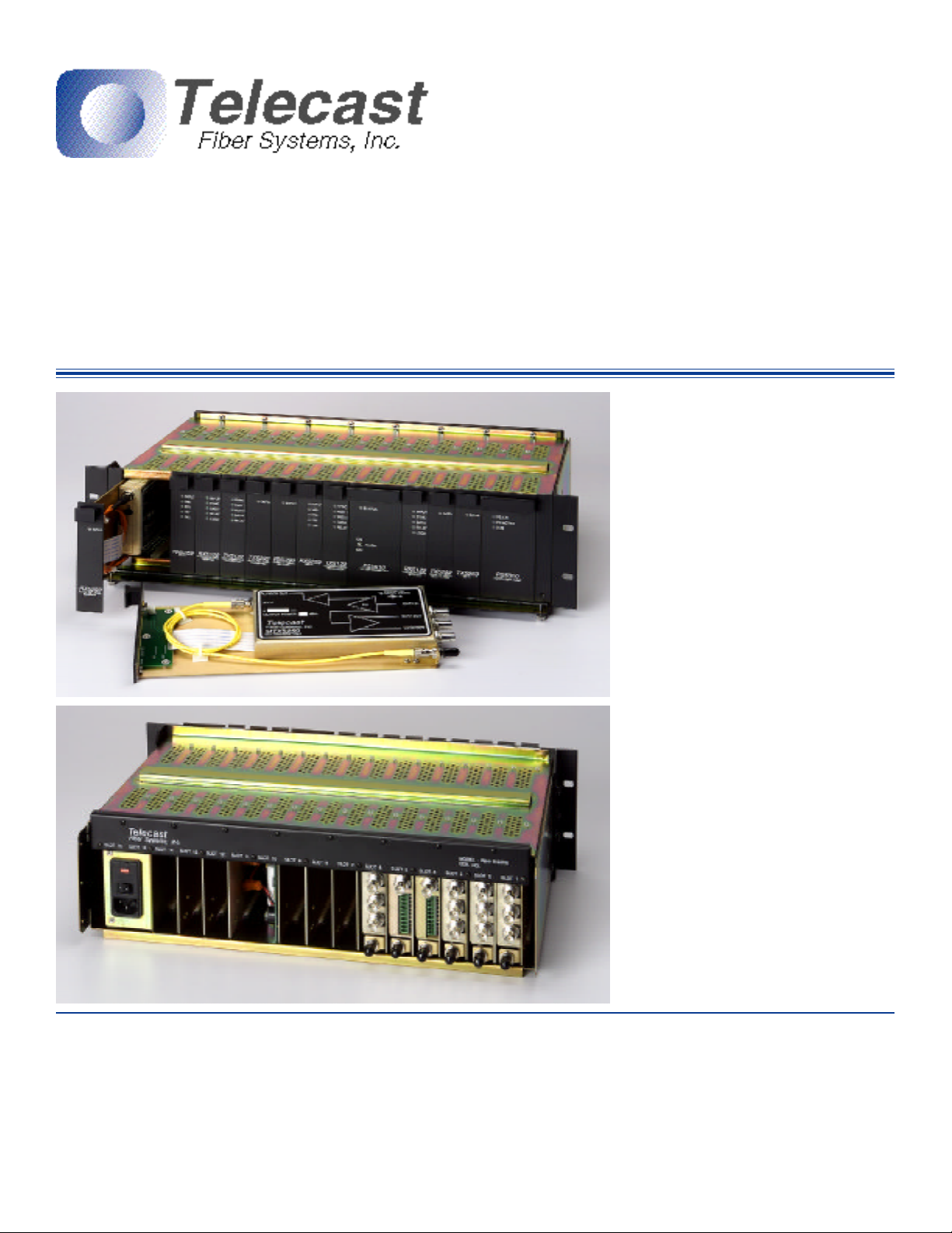
The Viper II frame is designed for "plug and
play" use. The Power Bus System allows for
the convenient placement of modules in any
orientation that suits the user.
The frame ships ready-to-use. Simply insert
your PS5000 Power Supply Unit and the
optional PS5010 Battery back-up unit, if
provided. The rear of the PS5000 features a
Power Entry Module that must be set for your
local AC power. A convenient window on the
module shows the voltage input setting, either
115 or 230 VAC. If adjustment is necessary,
see the Power Supply section on page 3.
Note that the frame can accommodate
additional PS5000's or PS5010's to ensure
uninterrupted power to your system. The
PS5000 ships with a North American type
power cord. You may need to replace this with
the appropriate IEC cord to accommodate
your local power outlets.
Specifications
Mechanical
Dimensions (WxLxD) 5.25" x 17.25" x 11"
Weights -Frame 9 lbs.
PS5000 5 lbs.
PS5010 3 lbs.
16 card slots, Max. of 14 modules plus PS5000
© 2001 Telecast Fiber Systems, Inc
Specifications subject to change without notice. Made in USA
Electrical
Input Voltage Range 100 to 240 VAC
Output Voltage Range 10 to 18 VDC
Power Consumption (per module) 3 watts
Power Consumption (Max) 50 watts
102 Grove Street; Worcester, MA 01605 USA Phone: (508)754-4858 FAX: (508)752-1520
e-mail: sales@telecast-fiber.com http://www.telecast-fiber.com
Once the power supplies have been properly
configured and inserted into the rack frame,
AC mains power can be supplied and
additional modules can then be inserted.
Modules can be hot-swapped at any time
without fear of damage. Care should be taken
when inserting modules to ensure that they go
in straight since improper insertion can result
in damage to the internal backplane power
connectors, explained further on page 2.
Environmental
Temperature Range -25° to +55°C
Humidity Range 0 to 95% RH, Noncond.
Page 2
Viper II Rack
General
The Viper II rack Frame (V2) is a 19" 3 RU
card cage designed to house the entire
line of Telecast Viper II modules. Each
frame has 16 slots that can be used to
accommodate both single and double-slot
modules and power supplies. Assuming
two slots for the main PS5000 power
module, the user is left with 14 slots for
functionality modules with the option of
adding multiple PS5000 or PS5010 Battery
Back-Up power modules for further
insurance against power outages.
The V2 frames uses a power bus system
using the "Future-Bus 24-pin header"
giving the user flexibility in the placement
of modules in the frame. The pinout for the
Future-Bus connector is shown at right.
The frame features a hinged front security
bar that is used to secure the modules.
The bar is locked down using the two
spring-screws located on each side of the
hinged panel.
Unpacking
To ensure that no damage occurs to the
V2 frame during shipment, it is packed and
shipped without modules inserted. Care
should be taken when removing it from its
packing materials. Inspect the unit closely
for loose screws, smooth hinge operation,
missing nylon card guides and/or cosmetic
damage. Any problems should be reported
to Telecast immediately.
To return an item for repair, call Telecast at
508-754-4858 to obtain a return material
authorization (RMA).
Note that the frames undergo an alignment
procedure during assembly and testing.
Any movement of the backplane will result
in the possibility of damaged pins in the
power connectors. Do not make adjustments to the position of the backplane
panel!
The Future-Bus Connector
DC power is
supplied to the
frame via a 24pin "Future-Bus"
connector. When
looking into the
frame, the pinouts are as
indicated in the picture to the right. The top
two rows of 4 pins are 0V Ground. The
middle two rows are for 10-18VDC OUT
and the last two rows are reserved for
future expansion of the Viper II system.
CAUTION: Care should be taken when
inserting and removing modules as these
pins are of a very fine pitch and can easily
be bent. If pins do become bent, contact
Telecast for an RMA number as it is not
recommended that the user attempt a
repair as failure to properly align the
backplane will result in additional bent
pins.
Installing Modules
The installation and removal of modules is
a very straight-forward process but, as
mentioned above, care should be taken to
ensure that no damage occurs as a result
of an improperly inserted module.
Each frame is equiped with nylon card
guides for each of the 16 slots. In cases
where the module is two spaces in width,
only the left-side guide is used.
Carefully align the module in the top and
bottom guides and slowly insert it. As the
rear end of the module nears the rear of
the frame, it will hit a riser-plate that serves
to lift the module so that the power
connectors will properly come together and
seat. You will "feel" this plate as you insert
the module and as you continue to insert it
you will "feel" the female power connector
on the module make smooth contact with
the male power plug in the frame. Any
GND
10-18VDC
Reserved
attempts to 'slam' the module into the
frame is likely to result in bent pins.
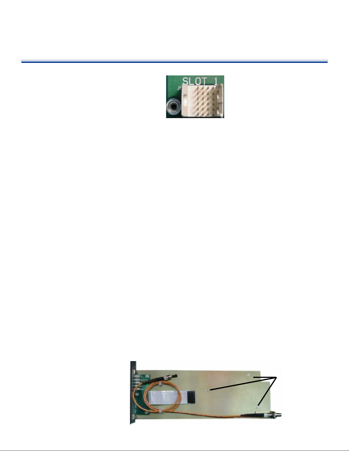
Converting "Throw-Down" Modules
Any of the Telecast Viper II "throw-down"
modules can easily be converted to fit in a
Viper II frame. A Rack Mount Kit (RMK) is
all that is required to make such a conversion. As the picture below illustrates, the
kit includes a metal spline with ST barrel, a
short ST-ST jumper cable and the frame
faceplate with a ribbon cable to transfer
LED indicator information from the module
to the new faceplate.
Installation involves removing the back
cover from the throw-down module. It is
secured with three machine screws. Once
the rear plate is removed, the module
simply installs onto the new spline with the
same three screws.
If you are converting a digital module, care
should be taken to ensure that the EMI
gasketing remains in position as the backplates are exchanged. Failure to do so
may increase the probability of RF/EMI
leakage from the module. Care should
also be taken in connecting the ribbon
cable and in the routing of the fiber jumper.
A pinched or too-tightly-coiled jumper
could impede optical performance.
When making this conversion, be sure
keep the old back-plate in a safe place for
future re-conversion back into the throwdown configuration.
Relevant Part Numbers
V2Frame-1 3 RU Viper II Cage
PS5000 Power Supply
PS5010 Battery back Up
RMK-XXXX Rack Mount Conversion
Kit. Contact Telecast for
Specific Model Numbers
BP5001 One-wide Filler Panel
BP5002 Two-Wide Filler Panel
11000-054 Throw-Down Back Plate
Rack ears are included with the frame and
are shipped attached.
Caution should be taken to ensure that the
hinged security bar is up and in the locked
position when modules are not being
installed. Failure to do so may result in
modules falling out of the frame if it were to
be inadvertantly tilted or moved.
Note the three holes
used in securing the
module to the spline
and the ST fiber
jumper and ribbon
cable that must be
attached.
Page 3

Power
PS5010
BATTERY BACKUP UNIT
PS5000
POWER SUPPLY UNIT
General
The PS5000 serves as the primary power
supply for the Viper II frame. It is a doublewide module that can be positioned
anywhere amongst the 16 slots of the
frame. Input power requirements are 100240VAC. A full frame will draw no more
than 750mA.
The PS5000 and the PS5010 are inserted
into the frame in the same way as any
other Viper II module however, due to the
extra weight of these modules, extra care
should be taken to ensure that they are
aligned properly.
Operation of the 115/230 VAC Power
Entry Module
The PS5000 features an AC Power Entry
Module that allows the user to set up the
unit to work within their local power
requirements. AC line voltage is supplied
to the rear of the module with a standard
IEC/NEMA type power cord. A window on
the Power Entry Module reflects the
current VAC setting of either 115 or 230V.
Verify that the voltages on the units are set
properly before operating the system. If the
input voltage must be changed, use the
following procedure:
1. Use a small, flat-blade screwdriver in
the notch at the top of the module to
gently pry open the module cover and
expose the fuse block. The cover is
hinged at the bottom and will open
easily.
2. Gently pop out the fuse block.
3. Turn the block over and replace it back
into the module.
4. Close the module cover.
Operation
Once the module is configured to your
local power, it is ready for use. There are
power switches on both the Power Entry
Module (PEM) and on the faceplate of the
module. If the PEM power switch is not in
the on position, the faceplate switch will
not function.
With the main switch "on" the faceplate
switches now becomes operational. When
the faceplate switch is in the "on" position,
the LED's will indicate the condition of both
the PS and the Power Bus of the frame:
For the PS OK LED, green indicates that it
is receiving AC line voltage and that input
voltage is within acceptable parameters.
The PS ACTIVE LED will turn green to
indicate that the PS is generating DC
voltage and sending it to the power bus.
The BUS LED monitors the voltage on the
power bus and will turn green to indicate
that 12-18VDC is present.
If any of the LEDs are red, then a fault
condition exists. Make sure that the power
entry module is set correctly. If so, then
check the backplane for bent pins. If there
are no obvious problems, contact Telecast
for an RMA number.
If the BUS LED turns
orange, indicating a DC
output between 10-12 VDC,
then you have either:
1. low input voltage
2. A power bus short or
3. A faulty functionality
module that is drawing
too much power.
STATUS
The PS5010 Battery Back-Up
When inserted into the frame, the PS5010
will supply up to 30 minutes of back-up DC
power in the event of a power failure. This
is accomplished through the use of two
banks of Ni-Cad batteries. All rules
concerning Ni-cads and "charge memory"
apply. If you find that your PS5010 is no
longer holding a sufficient charge, call
Telecast for an RMA number.
The PS5010 unit has two switches:
BATTERY Turns the unit on and off
ALARM When in OFF position,
this defeats the alarm
that would sound to
indicate an interruption
of mains power.
There is a single LED on the faceplate
indicating the STATUS of the unit:
RED Discharging
GREEN Charging
Note that if the BATTERY switch is left in
the ON position but the PS5000 is turned
OFF, the PS5010 will discharge until
dead.The STATUS LED will be RED to
indicate this discharge condition. Whenever powering down the frame, be sure to
switch both the PS5000 and the PS5010 to
the OFF position.
PS OK
PS ACTIVE
BUS
The new input voltage value will be
reflected in the voltage value window.
The same procedure is followed for fuse
replacement. Be careful to use ONLY
1Amp SLO-BLO fuses, 5 x 20mm.
Troubleshoot this by first
verifying proper input
voltage. Then check to
ensure that there are no bent
pins on the backplane. If the
fault persists, remove other
functionality modules, one by
one, to try to isolate the
excess power draw to a
single module.
If a functionality module is
found to be the source of the
problem, contact Telecast for
an RMA number.
BATTERY
ALARM
POWER
Page 4

8 SINGLEMODE LO ISOLATION
TYPE:
Fiber Systems, Inc.
1300/1550 WDM
1550
1300/1550
1300
1310nm
1550nm
132
Wavelength Division
WDM's
General
A WDM (Wavelength Division Multiplexer) is, in essence, a prism.
Whereas a prism divides light into all of its component colors, a
WDM is a passive device that is "tuned" to specific optical wavelengths. For the purposes of our systems, it gives us the ability to
put two different optical wavelengths onto a single optical fiber. As
the figure ot the right illustrates, by putting a 1310nm source into
the first leg (low side) of the WDM and a 1550nm source into the
third leg (high side) of the WDM a combined optical signal is
available on the second leg (IN/OUT). This combined signal can
then travel down the optical fiber into another WDM on the recieve
end of the system where the signals are seperated and sent to
their respective TX or RX modules. All telecast WDM's operate in
the same way, ie. leg 1 is for the lower wavelength, leg 2 is for
input/output and leg 3 is for the higher wavelength. WDM's are
also available for multimode 850/1300nm applications.
The Viper II system supports WDM's for both singlemode and
multimode operation.
The primary reason for using WDM devices is to reduce the
number of fibers required for your system. Since WDM's combine
two module sets onto one optical fiber, your fiber count is cut in
half.
Operation
When possible, there are a few conventions that should be
observed when using WDM's in Telecast systems.
1. Try to WDM a TX with an RX
2. Try to WDM different types of signals (5122 with a 5259)
Sometimes this is just not possible so in cases where like signals
are used in the same direction, the user should be aware that
there is a slight chance of crosstalk between the two signals. This
condition is rare.
Telecast analog modules such as the 5122 require the use of
HIGH ISOLATION WDM's to further prevent crosstalk. When
using WDM's with these modules on singlemode fiber, the
MWD5135-SA is highly recommended.
Multiplexers
WDM
Hook Up Procedure
All Telecast V2 WDM modules ship as single units. For most
applications, you will need to order two WDM's per link. Each
WDM ships with singlemode or multimode ST patch cords for
making the connections with the functional TX or RX modules.
The wavelength of each functionality module is indicated on the
side-panel decal. Choices are 850, 1300 and 1550nm. RX units
will be either 850 or 1300/1550. For convenience, place the WDM
module into the V2 frame between the two modules being
combined. This will facilitate easy identification and troubleshooting, if necessary.
Once the modules are in position in the V2 frame,
you can commence making the connections. Note
that the WDM is a passive device, and you can not
damage it by making an error in connecting it.
Caution: remember NOT to look directly into
connected patch cables as the may be connected to
an operating laser emitter. Eye damage could result!
Simply attach the LOW wavelength device to ST #1,
the HIGH wavelength device to ST #3 and the
outgoing fiber to ST #2. LED indications on the
respective modules will aid you in verifying these
connections once the frames are powered ON.
Troubleshooting
If you are certain that your connections are correct but the unit is
not working, optical power can be verified by using and optical
power meter (Telecast # PMTR-ST-3W) to verify the presence of
an optical signal at both the TX module and at the output (leg 2) of
the WDM. If the unit is not passing any optical power, contact
Telecast for an RMA number.
IN/OUT
Relevant Part Numbers
MWD813-M Multimode 62.5/125µ WDM Coupler with ST's.
MWD5135-M Multimode 50/125µ WDM coupler with ST's.
MWD5135-SD Singlemode 8/125µ WDM coupler with ST's.
MWD5135-SA Singlemode 8/125µ WDM coupler with ST's.
850/1300nm
1300/1550nm
1300/1550nm - Medium Isolation
1300/1550nm - High Isolation
62.5 MULTI-MODE
50 MULTI-MODE
FIBER
8 SINGLE-MODE HI ISOLATION
Telecast
MWD5135
MADE IN USA
102 Grove Street; Worcester, MA 01605 USA Phone: (508)754-4858 FAX: (508)752-1520
e-mail: sales@telecast-fiber.com http://www.telecast-fiber.com
 Loading...