

Page 1

UniCon g
NVISION Series Router Con guration Utility v12.0.0
User’s Guide
UG0022-05
25 Nov 2014
Page 2

Copyright & Trademark Notice
Copyright © 2014 Grass Valley. All rights reserved.
Belden, Belden Sending All The Right Signals, and the Belden logo are trademarks or
registered trademarks of Belden Inc. or its affiliated companies in the United States and
other jurisdictions. Grass Valley, NVISION, NV9000, NV9000-SE Utilities, and UniConfig are
trademarks or registered trademarks of Grass Valley. Belden Inc., Grass Valley, and other
parties may also have trademark rights in other terms used herein.
Terms and Conditions
Please read the following terms and conditions carefully. By using UniConfig
documentation, you agree to the following terms and conditions.
Grass Valley hereby grants permission and license to owners of UniConfig routers to use
their product manuals for their own internal business use. Manuals for Grass Valley products
may not be reproduced or transmitted in any form or by any means, electronic or
mechanical, including photocopying and recording, for any purpose unless specifically
authorized in writing by Grass Valley.
A Grass Valley manual may have been revised to reflect changes made to the product during
its manufacturing life. Thus, different versions of a manual may exist for any given product.
Care should be taken to ensure that one obtains the proper manual version for a specific
product serial number.
Information in this document is subject to change without notice and does not represent a
commitment on the part of Grass Valley.
Warranty information is available in the support section of the Grass Valley web site
(www.grassvalley.com).
Title UniConfig User’s Guide
Part Number UG0022-05
Revision 2.1 (25 Nov 14)
ii
Page 3
Change History
Rev. Date ECO Description Approved
1.0 02 Oct 07 13619 Initial Release DEM, RH, GW
1.1 13 Feb 09 15573 Software update. Corrections. DEM, D.Cox
1.2 31 Mar 09 15703 Format change. D.Cox
1.3 14 Dec 09 16272 Added EC9535 configuration, monitor connections. DEM
2.1 25 Apr 13 18826 Added NV8140. Updated format. Corrected errors. D.Cox
2.1 25 Nov 14 19357 Reformatted and slightly changed. D.Cox
Safety Compliance
FCC Statement
This equipment has been tested and found to comply with the limits for a Class A digital
device, pursuant to part 15 of the FCC Rules. These limits are designed to provide reasonable
protection against harmful interference when the equipment is operated in a commercial
environment. This equipment generates, uses, and can radiate radio frequency energy and,
if not installed and used in accordance with the instruction manual, may cause harmful
interference to radio communications. Operation of this equipment in a residential area is
likely to cause harmful interference in which case the user will be required to correct the
interference at his own expense.
UniConfig
User’s Guide
Declaration of Conformance (CE)
All of the equipment described in this manual has been designed to conform with the
required safety and emissions standards of the European Community. Products tested and
verified to meet these standards are marked as required by law with the CE mark.
When shipped into member countries of the European Community, this equipment is
accompanied by authentic copies of original Declarations of Conformance on file in the
Grass Valley offices in Grass Valley, California USA.
Software License Agreement and Warranty Information
Contact Grass Valley for details on the software license agreement and product warranty.
Important Safeguards and Notices
This section provides important safety guidelines for operators and service personnel.
Specific warnings and cautions appear throughout the manual where they apply. Please
iii
Page 4

read and follow this important information, especially those instructions related to the risk
of electric shock or injury to persons.
WAR NIN G
Any instructions in this manual that require opening the equipment cover or enclosure are
for use by qualified service personnel only. To reduce the risk of electric shock, do not
perform any service other than that contained in the operating instructions unless you are
qualified to do so.
Restriction on Hazardous Substances (RoHs)
Grass Valley is in compliance with EU Directive RoHS 2002/95/EC governing the restricted
use of certain hazardous substances and materials in products and in our manufacturing
processes.
Grass Valley has a substantial program in place for RoHS compliance that includes significant
investment in our manufacturing process, and a migration of Grass Valley product electronic
components and structural materials to RoHS compliance.
It is our objective at Miranda GVD to maintain compliance with all relevant environmental
and product regulatory requirements. Detailed information on specific products or on the
RoHS program at Grass Valley is available from Grass Valley Customer Support at
1-800-719-1900 (toll-free) or
1-530-265-1000 (outside the U.S.).
iv
Page 5
Symbols and Their Meanings
The lightning flash with arrowhead symbol within an equilateral triangle alerts the
user to the presence of dangerous voltages within the product’s enclosure that
may be of sufficient magnitude to constitute a risk of electric shock to persons.
The exclamation point within an equilateral triangle alerts the user to the presence
of important operating and maintenance/service instructions.
The Ground symbol represents a protective grounding terminal. Such a terminal
must be connected to earth ground prior to making any other connections to the
equipment.
The fuse symbol indicates that the fuse referenced in the text must be replaced
with one having the ratings indicated.
UniConfig
User’s Guide
The presence of this symbol in or on Grass Valley equipment means that it has been
designed, tested and certified as complying with applicable Underwriter’s
Laboratory (USA) regulations and recommendations.
The presence of this symbol in or on Grass Valley equipment means that it has been
designed, tested and certified as essentially complying with all applicable
European Union (CE) regulations and recommendations.
General Warnings
A warning indicates a possible hazard to personnel which may cause injury or death.
Observe the following general warnings when using or working on this equipment:
• Heed all warnings on the unit and in the operating instructions.
• Do not use this equipment in or near water.
• This equipment is grounded through the grounding conductor of the power cord. To
avoid electrical shock, plug the power cord into a properly wired receptacle before connecting the equipment inputs or outputs.
• Route power cords and other cables so they are not likely to be damaged.
• Disconnect power before cleaning the equipment. Do not use liquid or aerosol cleaners; use only a damp cloth.
• Dangerous voltages may exist at several points in this equipment. To avoid injury, do
not touch exposed connections and components while power is on.
• Do not wear rings or wristwatches when troubleshooting high current circuits such as
the power supplies.
v
Page 6

• To avoid fire hazard, use only the specified fuse(s) with the correct type number, voltage
and current ratings as referenced in the appropriate locations in the service instructions or on the equipment. Always refer fuse replacements to qualified service personnel.
• To avoid explosion, do not operate this equipment in an explosive atmosphere.
• Have qualified service personnel perform safety checks after any service.
General Cautions
A caution indicates a possible hazard to equipment that could result in equipment damage.
Observe the following cautions when operating or working on this equipment:
• When installing this equipment, do not attach the power cord to building surfaces.
• To prevent damage to equipment when replacing fuses, locate and correct the problem
that caused the fuse to blow before re-applying power.
• Use only the specified replacement parts.
• Follow static precautions at all times when handling this equipment.
• This product should only be powered as described in the manual. To prevent equipment damage, select the proper line voltage on the power supply(ies) as described in
the installation documentation.
• To prevent damage to the equipment, read the instructions in the equipment manual
for proper input voltage range selection.
• Some products include a backup battery. There is a risk of explosion if the battery is
replaced by a battery of an incorrect type. Dispose of batteries according to instructions.
• Products that have (1) no on/off switch and (2) use an external power supply must be
installed in proximity to a main power outlet that is easily accessible.
• To reduce the risk of electrical shock, plug each power supply cord into a separate
branch circuit having a separate service ground.
vi
Page 7

Table of Contents
1 Preface . . . . . . . . . . . . . . . . . . . . . . . . . . . . . . . . . . . . . . . . . . . . . . . . 1
Chapter Structure . . . . . . . . . . . . . . . . . . . . . . . . . . . . . . . . . . . . . . . . . . . . . . . . . . . . . . . . . . . . . . . . . . . . . . . . . . . . . . 1
The PDF Document . . . . . . . . . . . . . . . . . . . . . . . . . . . . . . . . . . . . . . . . . . . . . . . . . . . . . . . . . . . . . . . . . . . . . . . . . . . . . 2
Terms, Conventions and Abbreviations . . . . . . . . . . . . . . . . . . . . . . . . . . . . . . . . . . . . . . . . . . . . . . . . . . . . . . . . . . 2
2 Introduction . . . . . . . . . . . . . . . . . . . . . . . . . . . . . . . . . . . . . . . . . . . 3
Product Overview. . . . . . . . . . . . . . . . . . . . . . . . . . . . . . . . . . . . . . . . . . . . . . . . . . . . . . . . . . . . . . . . . . . . . . . . . . . . . . . 3
Storing Configuration Settings. . . . . . . . . . . . . . . . . . . . . . . . . . . . . . . . . . . . . . . . . . . . . . . . . . . . . . . . . . . . . . 3
Utilities . . . . . . . . . . . . . . . . . . . . . . . . . . . . . . . . . . . . . . . . . . . . . . . . . . . . . . . . . . . . . . . . . . . . . . . . . . . . . . . . . . . . 4
UniConfig Version . . . . . . . . . . . . . . . . . . . . . . . . . . . . . . . . . . . . . . . . . . . . . . . . . . . . . . . . . . . . . . . . . . . . . . . . . . 4
Supported Routers . . . . . . . . . . . . . . . . . . . . . . . . . . . . . . . . . . . . . . . . . . . . . . . . . . . . . . . . . . . . . . . . . . . . . . . . . . . . . . 4
3 Configuration Basics. . . . . . . . . . . . . . . . . . . . . . . . . . . . . . . . . . . . 5
Before Starting a Configuration. . . . . . . . . . . . . . . . . . . . . . . . . . . . . . . . . . . . . . . . . . . . . . . . . . . . . . . . . . . . . . . . . . 5
Launching UniConfig. . . . . . . . . . . . . . . . . . . . . . . . . . . . . . . . . . . . . . . . . . . . . . . . . . . . . . . . . . . . . . . . . . . . . . . . . . . . 6
How to Launch UniConfig . . . . . . . . . . . . . . . . . . . . . . . . . . . . . . . . . . . . . . . . . . . . . . . . . . . . . . . . . . . . . . . . . . 6
How to Connect to a Router Control Card . . . . . . . . . . . . . . . . . . . . . . . . . . . . . . . . . . . . . . . . . . . . . . . . . . . 6
Ethernet Connection . . . . . . . . . . . . . . . . . . . . . . . . . . . . . . . . . . . . . . . . . . . . . . . . . . . . . . . . . . . . . . . . . . 6
Serial Connection. . . . . . . . . . . . . . . . . . . . . . . . . . . . . . . . . . . . . . . . . . . . . . . . . . . . . . . . . . . . . . . . . . . . . . 6
Viewing Configurations . . . . . . . . . . . . . . . . . . . . . . . . . . . . . . . . . . . . . . . . . . . . . . . . . . . . . . . . . . . . . . . . . . . . . . . . . 7
How to View Current Configuration Settings . . . . . . . . . . . . . . . . . . . . . . . . . . . . . . . . . . . . . . . . . . . . . . . . 7
Writing Changes to the Control Card. . . . . . . . . . . . . . . . . . . . . . . . . . . . . . . . . . . . . . . . . . . . . . . . . . . . . . . . . . . . . 8
How to Write Changes. . . . . . . . . . . . . . . . . . . . . . . . . . . . . . . . . . . . . . . . . . . . . . . . . . . . . . . . . . . . . . . . . . . . . . 8
Applying Configurations to Another Control Card. . . . . . . . . . . . . . . . . . . . . . . . . . . . . . . . . . . . . . . . . . . . . . . . 8
How to Apply a Configuration to Another Control Card . . . . . . . . . . . . . . . . . . . . . . . . . . . . . . . . . . . . . . 8
USB-to-Serial Adapters . . . . . . . . . . . . . . . . . . . . . . . . . . . . . . . . . . . . . . . . . . . . . . . . . . . . . . . . . . . . . . . . . . . . . . . . . . 9
Network Basics. . . . . . . . . . . . . . . . . . . . . . . . . . . . . . . . . . . . . . . . . . . . . . . . . . . . . . . . . . . . . . . . . . . . . . . . . . . . . . . . . 10
4 Installation. . . . . . . . . . . . . . . . . . . . . . . . . . . . . . . . . . . . . . . . . . . . 13
Preparing for Installation . . . . . . . . . . . . . . . . . . . . . . . . . . . . . . . . . . . . . . . . . . . . . . . . . . . . . . . . . . . . . . . . . . . . . . . 13
Installing UniConfig . . . . . . . . . . . . . . . . . . . . . . . . . . . . . . . . . . . . . . . . . . . . . . . . . . . . . . . . . . . . . . . . . . . . . . . . . . . . 14
How to Install UniConfig. . . . . . . . . . . . . . . . . . . . . . . . . . . . . . . . . . . . . . . . . . . . . . . . . . . . . . . . . . . . . . . . . . . 14
5 Communication . . . . . . . . . . . . . . . . . . . . . . . . . . . . . . . . . . . . . . . 17
Communicating with a Router. . . . . . . . . . . . . . . . . . . . . . . . . . . . . . . . . . . . . . . . . . . . . . . . . . . . . . . . . . . . . . . . . . 17
Communicating with the Router for the First Time . . . . . . . . . . . . . . . . . . . . . . . . . . . . . . . . . . . . . . . . . 17
Front Serial Connection . . . . . . . . . . . . . . . . . . . . . . . . . . . . . . . . . . . . . . . . . . . . . . . . . . . . . . . . . . . . . . . . . . . 18
How to Make a Front Serial Connection . . . . . . . . . . . . . . . . . . . . . . . . . . . . . . . . . . . . . . . . . . . . . . . 18
Rear Serial Connection (DIAG Port). . . . . . . . . . . . . . . . . . . . . . . . . . . . . . . . . . . . . . . . . . . . . . . . . . . . . . . . . 18
How to Make a Rear Serial Connection . . . . . . . . . . . . . . . . . . . . . . . . . . . . . . . . . . . . . . . . . . . . . . . . 19
vii
Page 8

Table of Contents
Serial and Ethernet Settings . . . . . . . . . . . . . . . . . . . . . . . . . . . . . . . . . . . . . . . . . . . . . . . . . . . . . . . . . . . . . . . . . . . . 20
Changing UniConfig’s Serial Communication Parameters . . . . . . . . . . . . . . . . . . . . . . . . . . . . . . . . . . . 20
Changing the Control Card’s Serial Communication Parameters . . . . . . . . . . . . . . . . . . . . . . . . . . . . 21
Changing the Control Card’s IP Address . . . . . . . . . . . . . . . . . . . . . . . . . . . . . . . . . . . . . . . . . . . . . . . . . . . . 22
Communications Options . . . . . . . . . . . . . . . . . . . . . . . . . . . . . . . . . . . . . . . . . . . . . . . . . . . . . . . . . . . . . . . . . . . . . . 23
Retaining Serial Port Settings . . . . . . . . . . . . . . . . . . . . . . . . . . . . . . . . . . . . . . . . . . . . . . . . . . . . . . . . . . . . . . 23
How to Retain the Most Current Serial Communication Settings. . . . . . . . . . . . . . . . . . . . . . . . 23
Advanced Ethernet Communication Settings . . . . . . . . . . . . . . . . . . . . . . . . . . . . . . . . . . . . . . . . . . . . . . 24
Disabling an Ethernet Port. . . . . . . . . . . . . . . . . . . . . . . . . . . . . . . . . . . . . . . . . . . . . . . . . . . . . . . . . . . . . . . . . . . . . . 25
How to Disable Communication with a Control Card . . . . . . . . . . . . . . . . . . . . . . . . . . . . . . . . . . . . . . . 25
Reading and Writing Control Card Configurations. . . . . . . . . . . . . . . . . . . . . . . . . . . . . . . . . . . . . . . . . . . . . . . 25
Reading a Control Card’s Configuration . . . . . . . . . . . . . . . . . . . . . . . . . . . . . . . . . . . . . . . . . . . . . . . . . . . . 25
Writing a Control Card’s Configuration . . . . . . . . . . . . . . . . . . . . . . . . . . . . . . . . . . . . . . . . . . . . . . . . . . . . . 26
6 Partitions and Signal Types . . . . . . . . . . . . . . . . . . . . . . . . . . . . 27
About Partitions . . . . . . . . . . . . . . . . . . . . . . . . . . . . . . . . . . . . . . . . . . . . . . . . . . . . . . . . . . . . . . . . . . . . . . . . . . . . . . . 27
Configuration Window . . . . . . . . . . . . . . . . . . . . . . . . . . . . . . . . . . . . . . . . . . . . . . . . . . . . . . . . . . . . . . . . . . . . . . . . . 28
Partition Table . . . . . . . . . . . . . . . . . . . . . . . . . . . . . . . . . . . . . . . . . . . . . . . . . . . . . . . . . . . . . . . . . . . . . . . . . . . . 29
Read All and Write All . . . . . . . . . . . . . . . . . . . . . . . . . . . . . . . . . . . . . . . . . . . . . . . . . . . . . . . . . . . . . . . . . . . . . 30
Multiple Control Cards . . . . . . . . . . . . . . . . . . . . . . . . . . . . . . . . . . . . . . . . . . . . . . . . . . . . . . . . . . . . . . . . . . . . 30
Partition Types . . . . . . . . . . . . . . . . . . . . . . . . . . . . . . . . . . . . . . . . . . . . . . . . . . . . . . . . . . . . . . . . . . . . . . . . . . . . . . . . 30
Artificial Partition Types . . . . . . . . . . . . . . . . . . . . . . . . . . . . . . . . . . . . . . . . . . . . . . . . . . . . . . . . . . . . . . . . . . . 30
Monitor “Partition” . . . . . . . . . . . . . . . . . . . . . . . . . . . . . . . . . . . . . . . . . . . . . . . . . . . . . . . . . . . . . . . . . . . 31
Output Follow “Partition” . . . . . . . . . . . . . . . . . . . . . . . . . . . . . . . . . . . . . . . . . . . . . . . . . . . . . . . . . . . . . 31
Signal Types . . . . . . . . . . . . . . . . . . . . . . . . . . . . . . . . . . . . . . . . . . . . . . . . . . . . . . . . . . . . . . . . . . . . . . . . . . . . . . 31
Audio . . . . . . . . . . . . . . . . . . . . . . . . . . . . . . . . . . . . . . . . . . . . . . . . . . . . . . . . . . . . . . . . . . . . . . . . . . . . . . . . 31
Video . . . . . . . . . . . . . . . . . . . . . . . . . . . . . . . . . . . . . . . . . . . . . . . . . . . . . . . . . . . . . . . . . . . . . . . . . . . . . . . . 32
Machine Control. . . . . . . . . . . . . . . . . . . . . . . . . . . . . . . . . . . . . . . . . . . . . . . . . . . . . . . . . . . . . . . . . . . . . . 32
Reference Signals . . . . . . . . . . . . . . . . . . . . . . . . . . . . . . . . . . . . . . . . . . . . . . . . . . . . . . . . . . . . . . . . . . . . . . . . . 33
Partition Type and Reference Type Cross-Reference . . . . . . . . . . . . . . . . . . . . . . . . . . . . . . . . . . . 33
Setting Up Partitions . . . . . . . . . . . . . . . . . . . . . . . . . . . . . . . . . . . . . . . . . . . . . . . . . . . . . . . . . . . . . . . . . . . . . . . . . . . 33
Standalone v. Expanded Routers. . . . . . . . . . . . . . . . . . . . . . . . . . . . . . . . . . . . . . . . . . . . . . . . . . . . . . . . . . . 33
Standalone Routers. . . . . . . . . . . . . . . . . . . . . . . . . . . . . . . . . . . . . . . . . . . . . . . . . . . . . . . . . . . . . . . . . . . 34
Expanded Routers
Updating Partitions . . . . . . . . . . . . . . . . . . . . . . . . . . . . . . . . . . . . . . . . . . . . . . . . . . . . . . . . . . . . . . . . . . . . . . . 39
Mono v. Stereo Audio . . . . . . . . . . . . . . . . . . . . . . . . . . . . . . . . . . . . . . . . . . . . . . . . . . . . . . . . . . . . . . . . . . . . . . . . . . 40
Definitions and Concepts. . . . . . . . . . . . . . . . . . . . . . . . . . . . . . . . . . . . . . . . . . . . . . . . . . . . . . . . . . . . . . . . . . 40
Method 1 (under NV9000) . . . . . . . . . . . . . . . . . . . . . . . . . . . . . . . . . . . . . . . . . . . . . . . . . . . . . . . . . . . . . . . . . 41
Method 2 (under NV9000) . . . . . . . . . . . . . . . . . . . . . . . . . . . . . . . . . . . . . . . . . . . . . . . . . . . . . . . . . . . . . . . . . 41
Defining a ‘Monitor’ Level . . . . . . . . . . . . . . . . . . . . . . . . . . . . . . . . . . . . . . . . . . . . . . . . . . . . . . . . . . . . . . . . . . . . . . 42
NV8500 Standard Routers . . . . . . . . . . . . . . . . . . . . . . . . . . . . . . . . . . . . . . . . . . . . . . . . . . . . . . . . . . . . . . . . . 42
NV7256, NV7512, NV8256, NV8288. . . . . . . . . . . . . . . . . . . . . . . . . . . . . . . . . . . . . . . . . . . . . . . . . . . . . . . . . 43
In NV9000-SE Utilities. . . . . . . . . . . . . . . . . . . . . . . . . . . . . . . . . . . . . . . . . . . . . . . . . . . . . . . . . . . . . . . . . . . . . . 43
Defining an ‘Output Follow’ Level . . . . . . . . . . . . . . . . . . . . . . . . . . . . . . . . . . . . . . . . . . . . . . . . . . . . . . . . . . . . . . 43
Creating an Output Follow Level. . . . . . . . . . . . . . . . . . . . . . . . . . . . . . . . . . . . . . . . . . . . . . . . . . . . . . . . . . . 43
Example 1. . . . . . . . . . . . . . . . . . . . . . . . . . . . . . . . . . . . . . . . . . . . . . . . . . . . . . . . . . . . . . . . . . . . . . . . . . . . 44
Example 2. . . . . . . . . . . . . . . . . . . . . . . . . . . . . . . . . . . . . . . . . . . . . . . . . . . . . . . . . . . . . . . . . . . . . . . . . . . . 44
Cascading Outputs . . . . . . . . . . . . . . . . . . . . . . . . . . . . . . . . . . . . . . . . . . . . . . . . . . . . . . . . . . . . . . . . . . . 45
— Multiple Frames . . . . . . . . . . . . . . . . . . . . . . . . . . . . . . . . . . . . . . . . . . . . . . . . 36
7 Switch Point Settings . . . . . . . . . . . . . . . . . . . . . . . . . . . . . . . . . . 47
Background. . . . . . . . . . . . . . . . . . . . . . . . . . . . . . . . . . . . . . . . . . . . . . . . . . . . . . . . . . . . . . . . . . . . . . . . . . . . . . . . . . . . 47
Redundant v. Dual Video Reference. . . . . . . . . . . . . . . . . . . . . . . . . . . . . . . . . . . . . . . . . . . . . . . . . . . . . . . . 47
The Switch Point Setup Window. . . . . . . . . . . . . . . . . . . . . . . . . . . . . . . . . . . . . . . . . . . . . . . . . . . . . . . . . . . . . . . . 48
About Video Signal Fields and Frames . . . . . . . . . . . . . . . . . . . . . . . . . . . . . . . . . . . . . . . . . . . . . . . . . . . . . . . . . . 49
viii
Page 9

Setting Switching Parameters . . . . . . . . . . . . . . . . . . . . . . . . . . . . . . . . . . . . . . . . . . . . . . . . . . . . . . . . . . . . . . . . . . 49
NV5100MC or NV5128 Multi-Format Router . . . . . . . . . . . . . . . . . . . . . . . . . . . . . . . . . . . . . . . . . . . . . . . . 50
NV7256 and NV7256-Plus Routers . . . . . . . . . . . . . . . . . . . . . . . . . . . . . . . . . . . . . . . . . . . . . . . . . . . . . . . . . 52
NV7512 and NV7512-Plus Routers . . . . . . . . . . . . . . . . . . . . . . . . . . . . . . . . . . . . . . . . . . . . . . . . . . . . . . . . . 54
NV8256-Plus Routers . . . . . . . . . . . . . . . . . . . . . . . . . . . . . . . . . . . . . . . . . . . . . . . . . . . . . . . . . . . . . . . . . . . . . . 56
NV8288 and NV8288-Plus Routers . . . . . . . . . . . . . . . . . . . . . . . . . . . . . . . . . . . . . . . . . . . . . . . . . . . . . . . . . 58
NV8500 Family Standard Routers . . . . . . . . . . . . . . . . . . . . . . . . . . . . . . . . . . . . . . . . . . . . . . . . . . . . . . . . . . 60
8 Machine Control. . . . . . . . . . . . . . . . . . . . . . . . . . . . . . . . . . . . . . . 63
Background Information . . . . . . . . . . . . . . . . . . . . . . . . . . . . . . . . . . . . . . . . . . . . . . . . . . . . . . . . . . . . . . . . . . . . . . . 63
Machine Control Ports. . . . . . . . . . . . . . . . . . . . . . . . . . . . . . . . . . . . . . . . . . . . . . . . . . . . . . . . . . . . . . . . . . . . . 63
Machine Control Partitions . . . . . . . . . . . . . . . . . . . . . . . . . . . . . . . . . . . . . . . . . . . . . . . . . . . . . . . . . . . . . . . . 64
Broadcasting Machine Control Signals . . . . . . . . . . . . . . . . . . . . . . . . . . . . . . . . . . . . . . . . . . . . . . . . 65
Diagnostic Takes . . . . . . . . . . . . . . . . . . . . . . . . . . . . . . . . . . . . . . . . . . . . . . . . . . . . . . . . . . . . . . . . . . . . . . . . . . 65
The Port Configuration Window . . . . . . . . . . . . . . . . . . . . . . . . . . . . . . . . . . . . . . . . . . . . . . . . . . . . . . . . . . . . . . . . 66
Machine Control Port Commands. . . . . . . . . . . . . . . . . . . . . . . . . . . . . . . . . . . . . . . . . . . . . . . . . . . . . . . . . . 66
Setting Up Machine Control Ports . . . . . . . . . . . . . . . . . . . . . . . . . . . . . . . . . . . . . . . . . . . . . . . . . . . . . . . . . . . . . . 67
How to Configure Machine Control Ports. . . . . . . . . . . . . . . . . . . . . . . . . . . . . . . . . . . . . . . . . . . . . . . . . . . 67
9 Connections Window . . . . . . . . . . . . . . . . . . . . . . . . . . . . . . . . . . 69
Introduction . . . . . . . . . . . . . . . . . . . . . . . . . . . . . . . . . . . . . . . . . . . . . . . . . . . . . . . . . . . . . . . . . . . . . . . . . . . . . . . . . . . 69
Writing Connections Reports . . . . . . . . . . . . . . . . . . . . . . . . . . . . . . . . . . . . . . . . . . . . . . . . . . . . . . . . . . . . . . 70
The Connections Window . . . . . . . . . . . . . . . . . . . . . . . . . . . . . . . . . . . . . . . . . . . . . . . . . . . . . . . . . . . . . . . . . . . . . . 71
Window Features . . . . . . . . . . . . . . . . . . . . . . . . . . . . . . . . . . . . . . . . . . . . . . . . . . . . . . . . . . . . . . . . . . . . . . . . . 73
Views . . . . . . . . . . . . . . . . . . . . . . . . . . . . . . . . . . . . . . . . . . . . . . . . . . . . . . . . . . . . . . . . . . . . . . . . . . . . . . . . . . . . . 73
XY/Standard View . . . . . . . . . . . . . . . . . . . . . . . . . . . . . . . . . . . . . . . . . . . . . . . . . . . . . . . . . . . . . . . . . . . . 73
XY/Mono View . . . . . . . . . . . . . . . . . . . . . . . . . . . . . . . . . . . . . . . . . . . . . . . . . . . . . . . . . . . . . . . . . . . . . . . 74
Machine Control View . . . . . . . . . . . . . . . . . . . . . . . . . . . . . . . . . . . . . . . . . . . . . . . . . . . . . . . . . . . . . . . . 74
Saving and Loading Crosspoint States . . . . . . . . . . . . . . . . . . . . . . . . . . . . . . . . . . . . . . . . . . . . . . . . . . . . . 75
Setting Connection Window Options . . . . . . . . . . . . . . . . . . . . . . . . . . . . . . . . . . . . . . . . . . . . . . . . . . . . . . . . . . . 76
Connection Preferences Tab . . . . . . . . . . . . . . . . . . . . . . . . . . . . . . . . . . . . . . . . . . . . . . . . . . . . . . . . . . . . . . . 76
Automatic Refresh After Take . . . . . . . . . . . . . . . . . . . . . . . . . . . . . . . . . . . . . . . . . . . . . . . . . . . . . . . . . 76
Automatic Increment and Decrement after Takes. . . . . . . . . . . . . . . . . . . . . . . . . . . . . . . . . . . . . . 77
Machine Control Tab . . . . . . . . . . . . . . . . . . . . . . . . . . . . . . . . . . . . . . . . . . . . . . . . . . . . . . . . . . . . . . . . . . . . . . 77
‘Other’ Tab . . . . . . . . . . . . . . . . . . . . . . . . . . . . . . . . . . . . . . . . . . . . . . . . . . . . . . . . . . . . . . . . . . . . . . . . . . . . . . . . 78
Show Take Buttons on Connection Dialog . . . . . . . . . . . . . . . . . . . . . . . . . . . . . . . . . . . . . . . . . . . . . 78
Enable Output-Follow Takes . . . . . . . . . . . . . . . . . . . . . . . . . . . . . . . . . . . . . . . . . . . . . . . . . . . . . . . . . . 78
Salvo Tab . . . . . . . . . . . . . . . . . . . . . . . . . . . . . . . . . . . . . . . . . . . . . . . . . . . . . . . . . . . . . . . . . . . . . . . . . . . . . . . . . 79
Show Salvo Window . . . . . . . . . . . . . . . . . . . . . . . . . . . . . . . . . . . . . . . . . . . . . . . . . . . . . . . . . . . . . . . . . . 79
Send All Reads to Salvo Window . . . . . . . . . . . . . . . . . . . . . . . . . . . . . . . . . . . . . . . . . . . . . . . . . . . . . . 79
Viewing Diagnostic Crosspoint Data . . . . . . . . . . . . . . . . . . . . . . . . . . . . . . . . . . . . . . . . . . . . . . . . . . . . . . . . . . . . 80
How to View Crosspoints . . . . . . . . . . . . . . . . . . . . . . . . . . . . . . . . . . . . . . . . . . . . . . . . . . . . . . . . . . . . . . . . . . 80
Performing Takes . . . . . . . . . . . . . . . . . . . . . . . . . . . . . . . . . . . . . . . . . . . . . . . . . . . . . . . . . . . . . . . . . . . . . . . . . . . . . . 81
XY/Standard Signals. . . . . . . . . . . . . . . . . . . . . . . . . . . . . . . . . . . . . . . . . . . . . . . . . . . . . . . . . . . . . . . . . . . . . . . 81
How to Perform Standard Takes. . . . . . . . . . . . . . . . . . . . . . . . . . . . . . . . . . . . . . . . . . . . . . . . . . . . . . . 81
Mono Signals . . . . . . . . . . . . . . . . . . . . . . . . . . . . . . . . . . . . . . . . . . . . . . . . . . . . . . . . . . . . . . . . . . . . . . . . . . . . . 82
How to Perform Mono Takes . . . . . . . . . . . . . . . . . . . . . . . . . . . . . . . . . . . . . . . . . . . . . . . . . . . . . . . . . . 82
Machine Control Signals. . . . . . . . . . . . . . . . . . . . . . . . . . . . . . . . . . . . . . . . . . . . . . . . . . . . . . . . . . . . . . . . . . . 82
How to Perform Machine Control Takes . . . . . . . . . . . . . . . . . . . . . . . . . . . . . . . . . . . . . . . . . . . . . . . 83
Special Takes . . . . . . . . . . . . . . . . . . . . . . . . . . . . . . . . . . . . . . . . . . . . . . . . . . . . . . . . . . . . . . . . . . . . . . . . . . . . . . . . . . 87
Diagonal Takes. . . . . . . . . . . . . . . . . . . . . . . . . . . . . . . . . . . . . . . . . . . . . . . . . . . . . . . . . . . . . . . . . . . . . . . . . . . . 87
Notes . . . . . . . . . . . . . . . . . . . . . . . . . . . . . . . . . . . . . . . . . . . . . . . . . . . . . . . . . . . . . . . . . . . . . . . . . . . . . . . . 87
Range Takes . . . . . . . . . . . . . . . . . . . . . . . . . . . . . . . . . . . . . . . . . . . . . . . . . . . . . . . . . . . . . . . . . . . . . . . . . . . . . . 88
Notes . . . . . . . . . . . . . . . . . . . . . . . . . . . . . . . . . . . . . . . . . . . . . . . . . . . . . . . . . . . . . . . . . . . . . . . . . . . . . . . . 88
UniConfig
User’s Guide
ix
Page 10

Table of Contents
Reverse Diagonal Takes . . . . . . . . . . . . . . . . . . . . . . . . . . . . . . . . . . . . . . . . . . . . . . . . . . . . . . . . . . . . . . . . . . . 88
Notes . . . . . . . . . . . . . . . . . . . . . . . . . . . . . . . . . . . . . . . . . . . . . . . . . . . . . . . . . . . . . . . . . . . . . . . . . . . . . . . . 88
Chop Takes . . . . . . . . . . . . . . . . . . . . . . . . . . . . . . . . . . . . . . . . . . . . . . . . . . . . . . . . . . . . . . . . . . . . . . . . . . . . . . . 89
Output-Follow Takes . . . . . . . . . . . . . . . . . . . . . . . . . . . . . . . . . . . . . . . . . . . . . . . . . . . . . . . . . . . . . . . . . . . . . . 89
How to Perform a Single Output-Follow Take. . . . . . . . . . . . . . . . . . . . . . . . . . . . . . . . . . . . . . . . . . 89
How to Perform an Output-Follow Diagonal Take. . . . . . . . . . . . . . . . . . . . . . . . . . . . . . . . . . . . . . 90
10 EC9535 . . . . . . . . . . . . . . . . . . . . . . . . . . . . . . . . . . . . . . . . . . . . . . . 93
Setting Up EC9535 Communication . . . . . . . . . . . . . . . . . . . . . . . . . . . . . . . . . . . . . . . . . . . . . . . . . . . . . . . . . . . . 94
Connections . . . . . . . . . . . . . . . . . . . . . . . . . . . . . . . . . . . . . . . . . . . . . . . . . . . . . . . . . . . . . . . . . . . . . . . . . . . . . . 94
EC9535 and Router Baud Rates . . . . . . . . . . . . . . . . . . . . . . . . . . . . . . . . . . . . . . . . . . . . . . . . . . . . . . . . . . . . 94
Setting Up EC9535 Partitions . . . . . . . . . . . . . . . . . . . . . . . . . . . . . . . . . . . . . . . . . . . . . . . . . . . . . . . . . . . . . . . . . . . 95
How to Set Up Partitions for an EC9535 . . . . . . . . . . . . . . . . . . . . . . . . . . . . . . . . . . . . . . . . . . . . . . . . . . . . 96
Setting Up EC9535 Switch Points . . . . . . . . . . . . . . . . . . . . . . . . . . . . . . . . . . . . . . . . . . . . . . . . . . . . . . . . . . . . . . . 97
How to Make Switch Point Settings for the EC9535 . . . . . . . . . . . . . . . . . . . . . . . . . . . . . . . . . . . . . . . . . 97
11 NV8500 Monitors. . . . . . . . . . . . . . . . . . . . . . . . . . . . . . . . . . . . . 101
Monitor Overview. . . . . . . . . . . . . . . . . . . . . . . . . . . . . . . . . . . . . . . . . . . . . . . . . . . . . . . . . . . . . . . . . . . . . . . . . . . . . 101
UniConfig Settings . . . . . . . . . . . . . . . . . . . . . . . . . . . . . . . . . . . . . . . . . . . . . . . . . . . . . . . . . . . . . . . . . . . . . . . . . . . . 102
Mapping to the Monitor Level . . . . . . . . . . . . . . . . . . . . . . . . . . . . . . . . . . . . . . . . . . . . . . . . . . . . . . . . . . . . 102
How to Set Up a Monitor Level . . . . . . . . . . . . . . . . . . . . . . . . . . . . . . . . . . . . . . . . . . . . . . . . . . . . . . . 102
Using the Monitor Level . . . . . . . . . . . . . . . . . . . . . . . . . . . . . . . . . . . . . . . . . . . . . . . . . . . . . . . . . . . . . . . . . . . . . . . 103
12 Locks . . . . . . . . . . . . . . . . . . . . . . . . . . . . . . . . . . . . . . . . . . . . . . . . 105
How to Remove Locks. . . . . . . . . . . . . . . . . . . . . . . . . . . . . . . . . . . . . . . . . . . . . . . . . . . . . . . . . . . . . . . . . . . . . . . . . 105
13 Salvos . . . . . . . . . . . . . . . . . . . . . . . . . . . . . . . . . . . . . . . . . . . . . . .107
Introduction . . . . . . . . . . . . . . . . . . . . . . . . . . . . . . . . . . . . . . . . . . . . . . . . . . . . . . . . . . . . . . . . . . . . . . . . . . . . . . . . . . 107
Creating a Salvo. . . . . . . . . . . . . . . . . . . . . . . . . . . . . . . . . . . . . . . . . . . . . . . . . . . . . . . . . . . . . . . . . . . . . . . . . . . . . . . 110
How to Create a Salvo . . . . . . . . . . . . . . . . . . . . . . . . . . . . . . . . . . . . . . . . . . . . . . . . . . . . . . . . . . . . . . . . . . . . 110
Building a Salvo . . . . . . . . . . . . . . . . . . . . . . . . . . . . . . . . . . . . . . . . . . . . . . . . . . . . . . . . . . . . . . . . . . . . . . . . . . . . . . . 111
Reading Outputs from the Router. . . . . . . . . . . . . . . . . . . . . . . . . . . . . . . . . . . . . . . . . . . . . . . . . . . . . . . . . 111
Adding Individual Takes . . . . . . . . . . . . . . . . . . . . . . . . . . . . . . . . . . . . . . . . . . . . . . . . . . . . . . . . . . . . . . . . . . 112
How to Add Individual Takes. . . . . . . . . . . . . . . . . . . . . . . . . . . . . . . . . . . . . . . . . . . . . . . . . . . . . . . . . 112
Modifying Individual Takes Within a Salvo. . . . . . . . . . . . . . . . . . . . . . . . . . . . . . . . . . . . . . . . . . . . . . . . . 112
How to Modify Individual Takes . . . . . . . . . . . . . . . . . . . . . . . . . . . . . . . . . . . . . . . . . . . . . . . . . . . . . . 112
Salvo Management . . . . . . . . . . . . . . . . . . . . . . . . . . . . . . . . . . . . . . . . . . . . . . . . . . . . . . . . . . . . . . . . . . . . . . . . . . . 113
Saving a New Salvo. . . . . . . . . . . . . . . . . . . . . . . . . . . . . . . . . . . . . . . . . . . . . . . . . . . . . . . . . . . . . . . . . . . . . . . 113
Saving an Existing Salvo . . . . . . . . . . . . . . . . . . . . . . . . . . . . . . . . . . . . . . . . . . . . . . . . . . . . . . . . . . . . . . . . . . 113
Opening a Salvo. . . . . . . . . . . . . . . . . . . . . . . . . . . . . . . . . . . . . . . . . . . . . . . . . . . . . . . . . . . . . . . . . . . . . . . . . . 113
How to Open and Upload a Salvo . . . . . . . . . . . . . . . . . . . . . . . . . . . . . . . . . . . . . . . . . . . . . . . . . . . . . . . . . 113
Clearing a Salvo . . . . . . . . . . . . . . . . . . . . . . . . . . . . . . . . . . . . . . . . . . . . . . . . . . . . . . . . . . . . . . . . . . . . . . . . . . 114
How to Clear a Salvo. . . . . . . . . . . . . . . . . . . . . . . . . . . . . . . . . . . . . . . . . . . . . . . . . . . . . . . . . . . . . . . . . 114
14 Firmware . . . . . . . . . . . . . . . . . . . . . . . . . . . . . . . . . . . . . . . . . . . . 115
Viewing Control Card Firmware. . . . . . . . . . . . . . . . . . . . . . . . . . . . . . . . . . . . . . . . . . . . . . . . . . . . . . . . . . . . . . . . 115
How to View the Software List Using the ‘Basic’ Setting . . . . . . . . . . . . . . . . . . . . . . . . . . . . . . . . . . . . 116
How to View the Software List Using the ‘Expanded’ Setting . . . . . . . . . . . . . . . . . . . . . . . . . . . . . . . 116
Uploading a Firmware File. . . . . . . . . . . . . . . . . . . . . . . . . . . . . . . . . . . . . . . . . . . . . . . . . . . . . . . . . . . . . . . . . . . . . 118
x
Page 11

How to Upload New Firmware . . . . . . . . . . . . . . . . . . . . . . . . . . . . . . . . . . . . . . . . . . . . . . . . . . . . . . . . . . . . 118
Using Flash Configuration Files . . . . . . . . . . . . . . . . . . . . . . . . . . . . . . . . . . . . . . . . . . . . . . . . . . . . . . . . . . . . . . . 119
15 System Status . . . . . . . . . . . . . . . . . . . . . . . . . . . . . . . . . . . . . . . . 121
Viewing System Status . . . . . . . . . . . . . . . . . . . . . . . . . . . . . . . . . . . . . . . . . . . . . . . . . . . . . . . . . . . . . . . . . . . . . . . . 121
How to View System Status . . . . . . . . . . . . . . . . . . . . . . . . . . . . . . . . . . . . . . . . . . . . . . . . . . . . . . . . . . . . . . . 121
Performing System Tasks. . . . . . . . . . . . . . . . . . . . . . . . . . . . . . . . . . . . . . . . . . . . . . . . . . . . . . . . . . . . . . . . . . . . . . 122
System > Erase . . . . . . . . . . . . . . . . . . . . . . . . . . . . . . . . . . . . . . . . . . . . . . . . . . . . . . . . . . . . . . . . . . . . . . . . . . 122
System > Clear . . . . . . . . . . . . . . . . . . . . . . . . . . . . . . . . . . . . . . . . . . . . . . . . . . . . . . . . . . . . . . . . . . . . . . . . . . . 122
System > Recall Last Serial EE Write Status. . . . . . . . . . . . . . . . . . . . . . . . . . . . . . . . . . . . . . . . . . . . . . . . . 123
Controller State > Other Controller. . . . . . . . . . . . . . . . . . . . . . . . . . . . . . . . . . . . . . . . . . . . . . . . . . . . . . . . 123
Controller State > This Controller . . . . . . . . . . . . . . . . . . . . . . . . . . . . . . . . . . . . . . . . . . . . . . . . . . . . . . . . . 123
16 Logs . . . . . . . . . . . . . . . . . . . . . . . . . . . . . . . . . . . . . . . . . . . . . . . . . 125
Using the Logs Window . . . . . . . . . . . . . . . . . . . . . . . . . . . . . . . . . . . . . . . . . . . . . . . . . . . . . . . . . . . . . . . . . . . . . . . 125
Logging Modes . . . . . . . . . . . . . . . . . . . . . . . . . . . . . . . . . . . . . . . . . . . . . . . . . . . . . . . . . . . . . . . . . . . . . . . . . . 126
Operations. . . . . . . . . . . . . . . . . . . . . . . . . . . . . . . . . . . . . . . . . . . . . . . . . . . . . . . . . . . . . . . . . . . . . . . . . . . . . . . 127
17 Technical Details . . . . . . . . . . . . . . . . . . . . . . . . . . . . . . . . . . . . . 129
Router Expansion . . . . . . . . . . . . . . . . . . . . . . . . . . . . . . . . . . . . . . . . . . . . . . . . . . . . . . . . . . . . . . . . . . . . . . . . . . . . . 129
Expansion Configuration Settings. . . . . . . . . . . . . . . . . . . . . . . . . . . . . . . . . . . . . . . . . . . . . . . . . . . . . . . . . 129
NV5256 (Expanded) . . . . . . . . . . . . . . . . . . . . . . . . . . . . . . . . . . . . . . . . . . . . . . . . . . . . . . . . . . . . . . . . . 129
NV7256-Plus . . . . . . . . . . . . . . . . . . . . . . . . . . . . . . . . . . . . . . . . . . . . . . . . . . . . . . . . . . . . . . . . . . . . . . . . 130
NV7512-Plus . . . . . . . . . . . . . . . . . . . . . . . . . . . . . . . . . . . . . . . . . . . . . . . . . . . . . . . . . . . . . . . . . . . . . . . . 130
NV8256-Plus . . . . . . . . . . . . . . . . . . . . . . . . . . . . . . . . . . . . . . . . . . . . . . . . . . . . . . . . . . . . . . . . . . . . . . . . 131
NV8288-Plus . . . . . . . . . . . . . . . . . . . . . . . . . . . . . . . . . . . . . . . . . . . . . . . . . . . . . . . . . . . . . . . . . . . . . . . . . . . . . 131
NV8576-Plus . . . . . . . . . . . . . . . . . . . . . . . . . . . . . . . . . . . . . . . . . . . . . . . . . . . . . . . . . . . . . . . . . . . . . . . . . . . . . 131
Connectors . . . . . . . . . . . . . . . . . . . . . . . . . . . . . . . . . . . . . . . . . . . . . . . . . . . . . . . . . . . . . . . . . . . . . . . . . . . . . . . . . . . 132
Mono and Stereo Configuration Methods. . . . . . . . . . . . . . . . . . . . . . . . . . . . . . . . . . . . . . . . . . . . . . . . . . . . . . 132
Method 1 . . . . . . . . . . . . . . . . . . . . . . . . . . . . . . . . . . . . . . . . . . . . . . . . . . . . . . . . . . . . . . . . . . . . . . . . . . . . . . . . 132
Method 1 Details . . . . . . . . . . . . . . . . . . . . . . . . . . . . . . . . . . . . . . . . . . . . . . . . . . . . . . . . . . . . . . . . . . . . 132
Method 2 . . . . . . . . . . . . . . . . . . . . . . . . . . . . . . . . . . . . . . . . . . . . . . . . . . . . . . . . . . . . . . . . . . . . . . . . . . . . . . . . 138
Method 2 Details . . . . . . . . . . . . . . . . . . . . . . . . . . . . . . . . . . . . . . . . . . . . . . . . . . . . . . . . . . . . . . . . . . . . 138
UniConfig
User’s Guide
Glossary . . . . . . . . . . . . . . . . . . . . . . . . . . . . . . . . . . . . . . . . . . . . . . . .143
Index . . . . . . . . . . . . . . . . . . . . . . . . . . . . . . . . . . . . . . . . . . . . . . . . . . . 147
Contact Us . . . . . . . . . . . . . . . . . . . . . . . . . . . . . . . . . . . . . . . . . . . . . 153
xi
Page 12

Table of Contents
xii
Page 13

Chapter 1 provides an introduction to the UniConfig User’s Guide.
Topics
Chapter Structure . . . . . . . . . . . . . . . . . . . . . . . . . . . . . . . . . . . . . . . . . . . . . . . . . . . . . . . . . . . . . . . . . . . . . . . . . 1
The PDF Document . . . . . . . . . . . . . . . . . . . . . . . . . . . . . . . . . . . . . . . . . . . . . . . . . . . . . . . . . . . . . . . . . . . . . . . . 2
Terms, Conventions and Abbreviations . . . . . . . . . . . . . . . . . . . . . . . . . . . . . . . . . . . . . . . . . . . . . . . . . . . . . 2
Chapter Structure
The following chapters provide detailed instructions for all aspects of Router Configuration
Utility:
• Chapter 1, Preface, (this chapter) outlines ways to use this guide, and provides a list of terms
and conventions.
• Chapter 2, Introduction, provides a functional description of UniConfig.
• Chapter 3, UniConfig Basics, provides an overview of UniConfig’s windows and menus.
• Chapter 3, Configuration Basics, provides an overview of configuration tasks.
• Chapter 4, Installation, provides information on installing UniConfig.
• Chapter 5, Communication, provides information on setting up communication between
UniConfig and the router.
• Chapter 6, Partitions and Signal Types, provides information on creating partitions.
• Chapter 7, Switch Point Settings, provides information on making switch point settings.
• Chapter 9, Connections Window, provides information on crosspoints and performing takes.
• Chapter 8, Machine Control, provides information on machine control partitions and ports.
• Chapter 10, EC9535, provides information regarding the EC9535 GSC Node Controller, a
router interface.
• Chapter 11, NV8500 Monitors, provides information regarding NV8500 input and output
monitors.
• Chapter 12, Locks, provides information about releasing locks.
• Chapter 13, Salvos, provides information on salvos.
• Chapter 14, Firmware, provides information about updating firmware.
• Chapter 15, System Status, discusses the ‘System Status’ window.
• Chapter 16, Logs, discusses the ‘Logs’ window.
• Chapter 17, Tech nical De ta ils, provides supplementary, but important, information.
An Index
and Glossary are also provided for your reference.
Preface
1
Page 14

Preface
Preface
The PDF Document
This guide is provided in PDF format, allowing you to use Acrobat’s “bookmarks” to navigate to
any desired location. You can also easily print a hardcopy. Please note:
• Use the Table of Contents or the bookmarks page to jump to any desired section.
• Many hyperlinks are provided within the chapters.
• Use the index to jump to specific topics within a chapter. Each page number in the index is a
hyperlink.
• Use Acrobat’s ‘Go to Previous View’ and ‘Go to Next View’ buttons to retrace your complete
navigational path.
Use the ‘First Page’, ‘Previous Page’, and ‘Next Page’, and ‘Last Page’ buttons to go to the first, previous, next, or last page within a PDF file.
Note
To display the navigation buttons, right-click the Tool Bar area, and check ‘Navigation’.
• Use Acrobat’s extensive search capabilities, such as the ‘Find’ tool and ‘Search’ tool to per-
form comprehensive searches as required.
Terms, Conventions and Abbreviations
The following conventions are used throughout this guide:
• Notes, Cautions and Important messages are presented in note boxes.
• Entries written in bold-face or capital letters denote physical control panel buttons or GUI
buttons.
Click Apply to ...
Press the SRC 12 button.
• Entries in single quotes denote a field name, page name, or label.
The AES3 reference connection is labeled ‘AES3 REF 1’.
2
Page 15

Chapter 2 provides a brief functional description of UniConfig.
Topics
Product Overview . . . . . . . . . . . . . . . . . . . . . . . . . . . . . . . . . . . . . . . . . . . . . . . . . . . . . . . . . . . . . . . . . . . . . . . . . 3
Supported Routers . . . . . . . . . . . . . . . . . . . . . . . . . . . . . . . . . . . . . . . . . . . . . . . . . . . . . . . . . . . . . . . . . . . . . . . . . 4
UniConfig is a software application to set up and modify configurations of Grass Valley’s
NVISION series routers and to perform diagnostics. UniConfig runs on a PC and communicates
with a router through the router’s control card either serially or over Ethernet. UniConfig modifies settings on the router control card. Configuration settings vary depending on the router’s
matrix type, its communication protocol, and the level of complexity of the router’s partitioning.
You can also use UniConfig to upload new firmware to router control cards and to perform
minor adjustments, such as takes and lock releases, on a router that is in operation.
Product Overview
Introduction
A router’s control card handles communication between a router control system and the
router’s hardware.
There are several different protocols available by which the router control system can communicate with the control card.
In this chapter, we assume that UniConfig is interacting with one of Grass Valley’s NV9000 family
router control systems using Grass Valley’s Ethernet protocol (NVEP). This protocol is always
available through the router’s Ethernet connection. NVSP (the serial protocol) is always available
through the router’s ‘CTRL 2’ connections.
Third-party protocols can be active through the serial ‘CTRL 1’ connection only. The control card
allows only one third-party protocol to be loaded at any one time. For information on changing
control system protocols, contact Grass Valley Technical Support
.
Storing Configuration Settings
Configuration settings are stored in non-volatile memory (EEPROM) located on the router motherboard. The EEPROM stores all configuration settings entered through UniConfig except the
crosspoint switching data. Crosspoint data are stored on the control card in battery-backed
RAM.
Each control card in a router has its own memory. Both cards, if two are present (for redundancy), must be configured separately and identically.
3
Page 16
Introduction
Introduction
Utilities
UniConfig can be used to perform a variety of utility functions, such as running diagnostics or
viewing system status. In addition, UniConfig can be used to test and update router crosspoint
data independently of the router control system.
Grass Valley periodically updates UniConfig with new features and functionality. Contact Grass
Valley Technical Support for the latest version of UniConfig.
UniConfig Version
This document describes UniConfig version 12.0.0 communicating with a control card running
current firmware under Grass Valley’s NVEP protocol. If your specific version of UniConfig and
control card firmware and its protocol are different, some features or functions presented in this
guide might not be available on your system. Contact Grass Valley Technical Support
mation on obtaining the latest versions of UniConfig and firmware for your situation.
Upgrading control card firmware is recommended only if a specific feature or function you
require is not provided by your current version. In some cases, new hardware may be required to
execute the latest firmware revision.
for infor-
Supported Routers
UniConfig currently supports the following NVISION routers:
NVISION Router Control Card
NV5100 multi-format router (128×128) EM0374
NV5128 multi-format router (128×128) EM0374
NV5256 machine control router 256×256 expandable to 512×512 EM0374
NV7256 digital audio router (256×256)
NV7256-Plus digital audio router 256×256 expandable to 512×512
NV7512 digital audio router 512×512 expandable to 2048×2048 EM0374
NV8256-Plus digital video router 256×256 expandable to 1024×1024 EM0374
NV8288 digital video router (288×576)
NV8288-Plus digital video router 288×288 expandable to 576×576
NV8500 Family:
NV8144 digital video router 144×144
NV8140 digital video router 144×288
NV8280 digital video router 288×576
NV8576 digital video router 576×1152
NV8576-Plus digital video router 576×576 expandable to 1152×1152
EC9535 GSC Node Bus Converter (no signal inputs or outputs) EM0374
EM0374
EM0529
EM0666
Although the EC9535 is not a router, it is configurable in UniConfig.
The NV3512 expandable digital audio router, the NV3064 multi-format router, and the NV6000
series routers are not discussed in this document. Please contact Grass Valley Technical Support
for assistance.
4
Page 17

Configuration Basics
Chapter 3 discusses basic configuration tasks, including launching UniConfig, selecting a
control card, viewing data, and writing changes.
Topics
Before Starting a Configuration . . . . . . . . . . . . . . . . . . . . . . . . . . . . . . . . . . . . . . . . . . . . . . . . . . . . . . . . . . . . 5
Launching UniConfig . . . . . . . . . . . . . . . . . . . . . . . . . . . . . . . . . . . . . . . . . . . . . . . . . . . . . . . . . . . . . . . . . . . . . . 6
Viewing Configurations . . . . . . . . . . . . . . . . . . . . . . . . . . . . . . . . . . . . . . . . . . . . . . . . . . . . . . . . . . . . . . . . . . . . 7
Writing Changes to the Control Card . . . . . . . . . . . . . . . . . . . . . . . . . . . . . . . . . . . . . . . . . . . . . . . . . . . . . . . 8
Applying Configurations to Another Control Card . . . . . . . . . . . . . . . . . . . . . . . . . . . . . . . . . . . . . . . . . . 8
USB-to-Serial Adapters . . . . . . . . . . . . . . . . . . . . . . . . . . . . . . . . . . . . . . . . . . . . . . . . . . . . . . . . . . . . . . . . . . . . 9
Network Basics . . . . . . . . . . . . . . . . . . . . . . . . . . . . . . . . . . . . . . . . . . . . . . . . . . . . . . . . . . . . . . . . . . . . . . . . . . . 10
UniConfig is used for configuring the control cards of NVISION series routers (and other devices
having control cards). A router cannot function properly until its control card(s) has been
configured.
Configuration choices vary according to the router model and the communication protocol
loaded on the control card. After UniConfig reads the router model and control card protocol, it
determines which menu options and windows to display.
Before Starting a Configuration
Before starting configuration tasks, please review the following check list of required conditions:
• The Grass Valley router has all the desired input, output, crosspoint, and control cards
installed and is powered up. All required reference signals have been connected.
• You have a configuration PC with UniConfig installed. See Installation on page 13. This PC
must be on the same Ethernet network as the router(s) you wish to configure.
• The router control system that will be used to control the router is available and ready for
configuration.
5
Page 18
Configuration Basics
Configuration Basics
Launching UniConfig
How to Launch UniConfig
Select ‘Programs > NVISION > UniConfig’ from the Windows ‘Start’ menu, or click the UniConfig
shortcut on your desktop:
How to Connect to a Router Control Card
If you do not know the IP address of your router’s control card, or if the control card is not accessible over Ethernet, on your PC, you must make a serial connection to the control card. The
details of that are explained in Communication
If your PC has an Ethernet connection to the control card, connection is much simpler.
Ethernet Connection
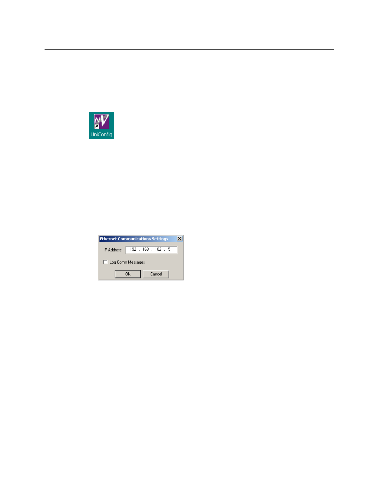
1 Click ‘Ethernet’ in the ‘Communications’ menu (if you have not done so already).
2 Either click ‘Setup’ in the ‘Communications’ menu and enter an IP address in the dialog:
on page 17.
3 Or, choose a control card from the control cards pane.
4 In the ‘Configuration’ window for this control card, click ‘Read All’.
The control card must be accessible among the networks to which your PC is connected.
Serial Connection
Serial connections require your PC to have either a serial port or a USB-to-serial adapter for
use with a USB port.
Selecting a control card on a serial connection means running a serial cable from a COM port of
your PC to a DE9 port of the control card itself. (The DE9 port to use is either at the front of the
card or at the rear of the router frame.)
There are several methods for connecting to a control card serially. The method you choose
depends on the router control card:
• EM0374 — Use the DE9 connector at the front of the control card. (Routers that use the
EM0374 are the NV5128, NV5256, NV7256, NV7512, NV8256-Plus, and the NV5100MC. The
EC9535 also uses EM0374 control cards.)
The connection is RS-232, 9600 Baud, 8N1.
(You can use the router’s rear connector after you first set up communication using the front
connector.)
6
Page 19
• EM0529 — The NV8288 and the NV8288-Plus use this control card. Connect to the rear diag-
nostic port of the router frame. There are two ports. Use the one for the control card you
want to configure. (Both control cards must eventually be configured identically.)
The connection is RS-232, 38400 Baud, 8N1.
• EM0666 — This card is used by NV8500 family standard routers. Connect to the rear diagnos-
tic port of the router frame. There are two ports. Use the one for the control card you want to
configure. (Both control cards must eventually be configured identically.)
The connection is RS-232, 38400 Baud, 8N1.
See Communication
The control cards on a router must be configured separately and identically.
on page 17 for complete details.
Viewing Configurations
After you have connected to a control card, go to the ‘Configuration’ window.
How to View Current Configuration Settings
1 Select a control card.
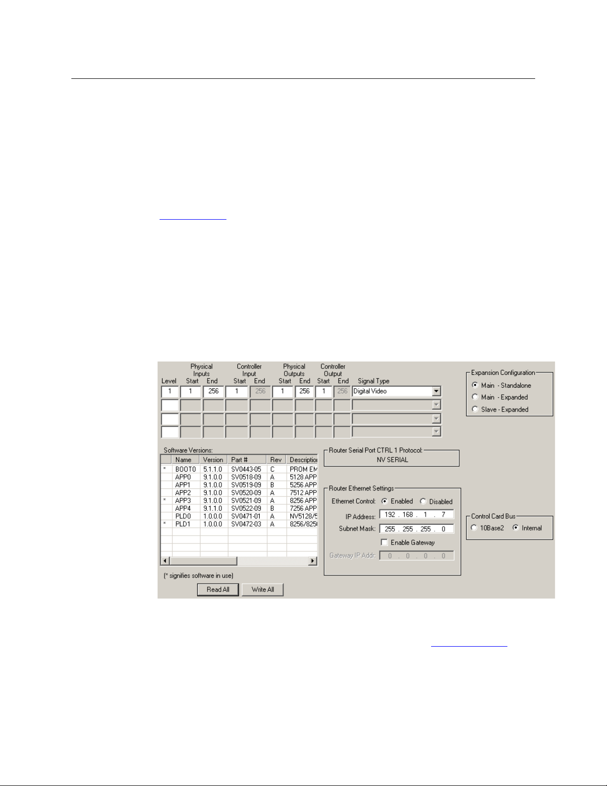
2 Go to the ‘Configuration’ window:
UniConfig
User’s Guide
Fig. 3-1: Configuration Window (NV8256 Sample)
3Click Read All. Current configuration data populate the ‘Configuration’ window.
If ‘Auto Refresh’ is enabled, it is not necessary to click Read All. See Automatic Refresh
page 15.
on
7
Page 20

Configuration Basics
Configuration Basics
Writing Changes to the Control Card
UniConfig does not save any changes in your PC’s file system. Configuration changes you make
are written to the EEPROM on the motherboard in the router frame. Each of a router’s control
cards has its own independent EEPROM. This means that changes must be made to each control
card separately and identically.
When written, changes are global and immediately overwrite any previous settings. There is
no way to undo a “write.”
How to Write Changes
1 In the currently open UniConfig window in which changes have been made, click Write or
Write All. If the changes are successfully written to the control card, a dialog appears
prompting you to reboot the control card.
2Click Ye s to reboot the control card. All crosspoint settings are maintained during the reboot
cycle but crosspoints cannot be changed until the control card has finished rebooting.
Or, click No if you want to reboot at a later time. Changed settings are stored in EEPROM, but
are not copied into the RAM used by the control card. The system will continue to run using
the previous settings until a reboot is performed.
Applying Configurations to Another Control Card
Once a configuration has been defined, the configuration settings can be applied to multiple
control cards.
How to Apply a Configuration to Another Control Card
1 Select a control card. (This the “from” control card.)
2 Go to the ‘Configuration’ window.
3Click Read All. Current configuration settings for the selected control card populate the
‘Configuration’ window fields.
4 Ensure that ‘Auto-refresh’ is disabled. (See Automatic Refresh
5 Select another control card
Do not click Read All.
6 Important: Enter the “to” control card’s IP address (and its subnet mask and gateway
address, if necessary) in the Ethernet settings section of the page.
If you do not change the IP address, you will write the configuration back to the “from” control card.
7 In the ‘Configuration’ window, click Write All. UniConfig sends the current configuration to
the selected control card.
8 Repeat steps 5–7 for additional target control cards.
— one to which you want to copy the current configuration.
on page 15.)
8
Page 21
USB-to-Serial Adapters
Older PCs have one or more DE9 COM ports. Newer PCs do not have them.
You can obtain a USB-to-serial conversion kit. With the software in the kit, a USB port acts a serial
port.
Following is one solution.
Obtain a USB-to-Serial-Value kit from SIIG, Inc. (www.siig.com). The kit includes a software CD
and a USB-to-DE9 cable.
Install their driver. The driver (software) will perform USB-to-serial conversion.
After loading the software, determine which COM ports are available:
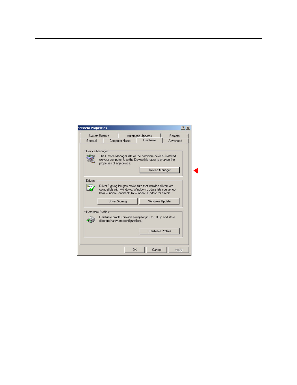
1 Go to the Windows System Properties dialog:
UniConfig
User’s Guide
9
Page 22
Configuration Basics
Configuration Basics
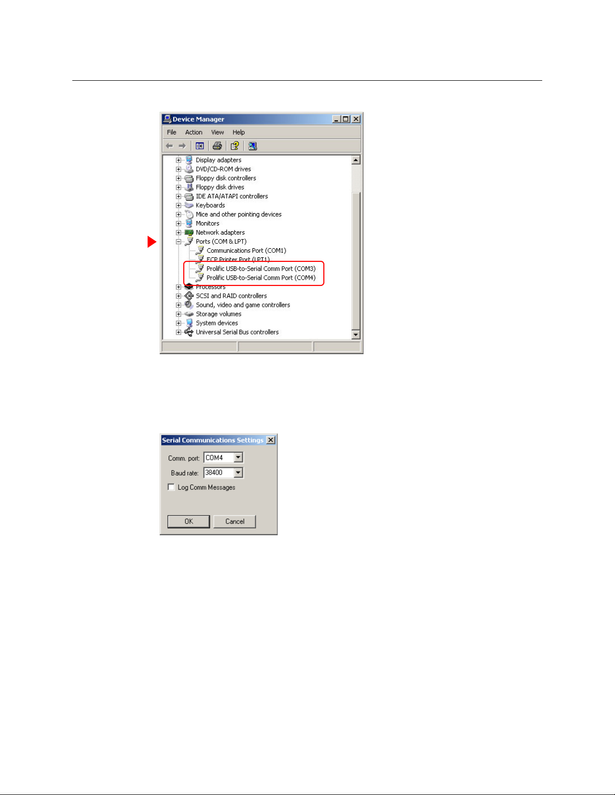
Click the ‘Device Manager’ button. The ‘Device Manager’ window opens:
2 Locate, and expand, the ‘Ports (COM & LPT)’ entry. You should see entries listing the COM
ports that are associated with USB ports. (The window details and the nomenclature might
differ if you are using Windows 7 or a driver from a different supplier.)
3 In UniConfig’s ‘Serial Communications Settings’ dialog, choose one of those ports as the
COM port:
Network Basics
For devices to communicate over Ethernet, all devices must reside on the same subnet or have
access to the subnet through a gateway.
Each control card on an NV9000 router network must have a unique IP address.
An IP address is a 32-bit number divided into two portions, one identifying the subnet and the
other specifying the address of a device within the subnet. A subnet mask specifies where in the
IP address the division occurs.
An IP address is usually represented by four 8-bit values (octets) written in decimal. The typical
IP address for a router in an NV9000 system is
192.168.1.nnn where nnn ranges from 1 to 254
10
Page 23

UniConfig
User’s Guide
and its subnet mask is typically 255.255.255.000. That mask means that 24 bits are used for the
subnet and 8 bits are used for the device address.
(Device addresses 0 and 255 are reserved for other purposes and may not be used.)
IP addresses for router control cards must be fixed addresses. DHCP
1
is not used.
IP addresses are divided into classes. Specific classes are intended for different functions. For
example, IP addresses on the 192.168.xxx.xxx subnet are known as class C addresses and are
intended for use in private closed networks. This range is recommended for use with all Grass
Valley products using a fixed IP structure.
Barring any IP addresses provided by your IT administrator, we suggest the following IP address
settings for router control cards:
Router Primary Control Card Secondary Control Card
First router 192.168.1.5 192.168.1.6
Second router 192.168.1.7 192.168.1.8
Third router 192.168.1.9 192.168.1.10
Fourth router 192.168.1.11 192.168.1.12
. . .
With these IP addresses, your configuration PC should configured so that one of its IP addresses
is 192.168.1.nnn where nnn is different from any address used by the routers.
All Grass Valley routers support Ethernet communication at 100
Mb/s.
1. Dynamic Host Configuration Protocol
11
Page 24

Configuration Basics
Configuration Basics
12
Page 25

Chapter 4 provides installation instructions.
Topics
Preparing for Installation . . . . . . . . . . . . . . . . . . . . . . . . . . . . . . . . . . . . . . . . . . . . . . . . . . . . . . . . . . . . . . . . . 13
Installing UniConfig . . . . . . . . . . . . . . . . . . . . . . . . . . . . . . . . . . . . . . . . . . . . . . . . . . . . . . . . . . . . . . . . . . . . . . 14
Preparing for Installation
You will need a PC with the following features to use UniConfig:
Windows® 2000, Windows XP Professional,® or Windows 7.® UniConfig does not run
under any version of the Macintosh or Linux operating system.
A late model Pentium-class processor, such as a Pentium III (or later) or an AMD Athlon.
At least 90
A CD drive.
256
At least one RS-232 serial port capable of running at 38400 bps or more. Note that many
USB-to-serial adapters do not function correctly at higher Baud rates.
A 10/100baseT Ethernet port that can use a fixed IP address on the same network as your
NVISION series routers.
MB of disk space.
MB or more RAM.
Installation
You will need the following items to use UniConfig:
100
Mb/s Ethernet switch with at least 4 ports.
Ethernet cables (category 5 or better).
Straight-through RS-232 serial cable.
13
Page 26
Installation
Installation
Installing UniConfig
UniConfig is available on Grass Valley’s Software and Documentation CD (SB0033-xx). You can
obtain the most recent release of UniConfig through Grass Valley customer service.
How to Install UniConfig
1 Obtain the Software and Documentation CD (SB0033) and insert in your CD drive.
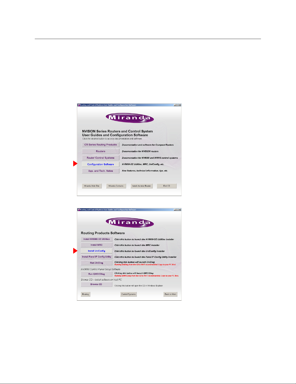
2 The CD should “autoplay.” The main screen appears:
3 Click ‘Configuration Software’. The configuration software page appears:
14
Page 27
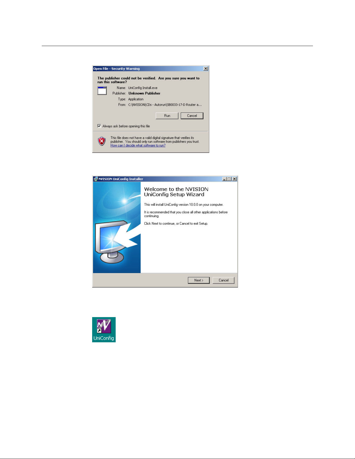
4 Click ‘Install UniConfig’. You will see a warning message:
You may safely disregard the warning. Click ‘Run’ to proceed.
5 The UniConfig installer will launch:
UniConfig
User’s Guide
6 Follow the simple instructions, clicking ‘Next’ to proceed from step to step. The actual instal-
lation takes about 30 seconds. By default, the installer creates an entry in the Windows ‘Start’
menu and also creates a shortcut on your desktop:
The default pathname of the application is:
C:\Program Files\NVISION\UniConfig\UniConfig.exe
The default path in the Windows Start menu is:
Programs > NVision > UniConfig
15
Page 28

Installation
Installation
16
Page 29

Communication
Chapter 5 discusses how UniConfig communicates with routers.
Topics
Communicating with a Router . . . . . . . . . . . . . . . . . . . . . . . . . . . . . . . . . . . . . . . . . . . . . . . . . . . . . . . . . . . . 17
Serial and Ethernet Settings . . . . . . . . . . . . . . . . . . . . . . . . . . . . . . . . . . . . . . . . . . . . . . . . . . . . . . . . . . . . . . . 20
Communications Options . . . . . . . . . . . . . . . . . . . . . . . . . . . . . . . . . . . . . . . . . . . . . . . . . . . . . . . . . . . . . . . . 23
Reading and Writing Control Card Configurations . . . . . . . . . . . . . . . . . . . . . . . . . . . . . . . . . . . . . . . . 25
Disabling an Ethernet Port . . . . . . . . . . . . . . . . . . . . . . . . . . . . . . . . . . . . . . . . . . . . . . . . . . . . . . . . . . . . . . . . 25
UniConfig can communicate with any NVISION series router’s control card through its Ethernet
port. Depending on the router, it can also communicate either through a serial port located at
the rear of the router, or through a serial port located at the front of the control card.
Note
If your router has two control cards, use UniConfig to configure each control card separately and identically. Each of the control cards must have a unique IP address, however.
EC9535s are not routers but they do have (EM0374) control cards. For information on setting
up EC9535 communication, see EC9535
Use MRC, not UniConfig, to configure NV8500 family hybrid routers (which have EM0833
control cards).
Communicating with a Router
Communicating with the Router for the First Time
The first time you configure a router, it is likely not to have an IP address. You must use the
router’s serial connection with UniConfig to assign the router’s control card its IP address. If the
router has two control cards, you must assign an IP address to both. After you perform this
simple step, you can use the router’s Ethernet connection to perform configuration tasks.
Ethernet is generally preferable. You can access multiple routers, perhaps remotely, and you do
not have to make cable connections for each change. Ethernet is also faster when you are
uploading firmware to the router.
on page 93.
17
Page 30

Communication
Communication
Front Serial Connection
(Front serial connections apply only to routers with EM0374 control cards.)
Make a connection between the router and UniConfig. Run a cable from your PC’s serial port to
the DE9 serial port located on the front of the control card. This connection is set to a fixed rate
of 9600
How to Make a Front Serial Connection
Baud. (The protocol is RS-232, 8N1, meaning 8 data bits, no parity, and 1 stop bit).
1 Open the router door and locate the control card.
2 Run a straight-through serial cable from your PC’s serial port to the DE9 connector at the
front of the control card.
If your PC does not have a serial port, you’ll need a USB-to-serial adapter for the cable. See
USB-to-Serial Adapters
3 Close the router door as much as possible. The router might overheat if you leave the door
open.
4 Set up serial communication in UniConfig. That is, choose serial mode and set the RS-232
settings to 9600. See Changing UniConfig’s Serial Communication Parameters
5 Read the control card configuration from the router. See Reading a Control Card’s Configura-
tion on page 25. If the read is successful, your serial connection is good.
(If the read is not successful, you will need to diagnose and correct the problem. The problem could be a faulty cable or that you have used a crossover cable by mistake. The problem
might lie in UniConfig: its Baud rate not set to 9600, the wrong COM port or the wrong connector chosen.)
6 Be sure to close the router door again when you have finished with its control cards.
on page 9.
on page 20.
Rear Serial Connection (DIAG Port)
(The serial connection for routers with EM0529 control cards or EM0666 control cards must be
made through the DIAG connectors at the rear of the router.)
(It is your option, after you have initially set up a router having an EM0374 control card, to access
the control card through its rear DIAG port.)
There are two serial ports located on the router, labeled ‘DIAG’. One is for the primary
card and the other is for the secondary control card. By default, these ports are set to 38400
Baud, RS-232, but can be changed to RS-422 in UniConfig. Do not change them to RS-422.
1. The terms “primary” and “secondary” mean nothing more than to distinguish the two control cards.
1
control
18
Page 31

UniConfig
VIDEO
REF 2
LOOP
AUX 1
AUX 2
CTRL 1
CTRL 1
CTRL 2
CTRL 2
ALARMS
POWER SUPPLY
MONITORS
POW
TIME
CODE
PRI CTRL
SEC CTRL
DIAG (38.4 Kbaud)
DIAG (38.4 Kbaud)
DIAG (38.4 Kbaud)
CONTROL
RTR EXP IN
AES REF 1
AES REF 2
VIDEO REF 2
VIDEO REF 1
RTR EXP
10/100 BT
RTR EXP
10/100 BT
CTRL 1
CTRL 2
CTRL 1
CTRL 2
DIAG (38.4 Kbaud)
PRI
SEC
SEC
PRI
User’s Guide
How to Make a Rear Serial Connection
1 Locate the permanent serial ports on the rear of the router, as shown in Figure 5-2. On the
NV8288 and NV8288-Plus, the ports are labeled ‘DIAG (38400 Baud)’:
Fig. 5-1: Serial Ports (Rear View, NV8288, NV8288-Plus)
On the NV8500 family routers, the ports are also labeled ‘DIAG (38400 Baud)’, but in a different orientation: This shows the NV8144:
Fig. 5-2: Serial Ports (Rear View, NV8144)
2 Run a straight-through serial cable from your PC’s serial port to the diagnostic connector.
If your PC does not have a serial port, you’ll need a USB-to-serial adapter for the cable. See
USB-to-Serial Adapters
on page 9.
3 Set up serial communication in UniConfig. That is, choose serial mode and set the RS-232
settings to 38400. See Changing UniConfig’s Serial Communication Parameters
, following.
4 Ensure that the control card’s DIAG port is set to RS-232 and 38400 Baud. See Changing the
Control Card’s Serial Communication Parameters on page 21.
5 Read the control card configuration from the router. See Reading a Control Card’s Configura-
tion on page 25. If the read is successful, your serial connection is good.
(If the read is not successful, you will need to diagnose and correct the problem. The problem could be a faulty cable or that you have used a crossover cable by mistake. The problem
might lie in UniConfig: its Baud rate not set properly, the wrong COM port or the wrong connector chosen.)
19
Page 32

Communication
Communication
Serial and Ethernet Settings
Changing UniConfig’s Serial Communication Parameters
1 From the ‘Communications’ menu, click ‘Serial’. This places UniConfig in serial mode.
2 Again from the ‘Communications’ menu, click ‘Setup’. The ‘Serial Communications’ dialog
appears:
From the ‘Comm port’ drop-down list, select the communication port number that matches
the port you are using on the configuration PC running UniConfig.
From the ‘Baud Rate’ drop-down list, select a Baud rate. Select 9600 for a front connection to
EM0374 cards. Select 38400 for a rear DIAG connection to any router’s control card.
3Click OK to accept the settings or, click Cancel to close the dialog without making any-
changes.
20
Page 33

UniConfig
User’s Guide
Changing the Control Card’s Serial Communication Parameters
1 Select a control card. In Ethernet mode, use the control card pane or enter the card’s present
IP address manually. In serial mode, run a cable to the applicable serial port of the control
card. See How to Connect to a Router Control Card
2 From the ‘Window’ menu, select ‘Router Serial Configuration’. The ‘Router Serial Configura-
tion’ window appears:
on page 6.
3Click Read to acquire the control card’s settings. (Doing so might not be necessary, but it is
not harmful, at this step.)
4 In the ‘Router Serial Configuration’ window, make settings as follows:
The first 3 regions of this window are for connections between the router and a router control system. Only the last region, “Rear Diagnostic Port” has any relation to UniConfig:
a In the ‘Rear Diagnostic Port’ section, select a ‘Port type’ and ‘Baud rate’ from the drop-
down lists. Choose ‘RS232’ and ‘38400’. (These are the defaults.)
b Click Write to write changes to the control card.
WAR NIN G
Do not click Read again before you have written the new data to the control card.
Clicking Read reads all settings from the control card, overwriting any changes you
have entered and does so without warning.
21
Page 34

Communication
Communication
Changing the Control Card’s IP Address
1 Select a control card. In Ethernet mode, use the control card pane or enter the card’s present
IP address manually. In serial mode, run a cable to the applicable serial port of the control
card. See How to Connect to a Router Control Card
2 From the ‘Window’ menu, select ‘Configuration’. The ‘Configuration’ window appears. This
example is the configuration window for an NV8256:
on page 6.
3 In the ‘Configuration’ window, click Read All. UniConfig populates the ‘Configuration’ win-
dow with the current router configuration.
4 In the ‘Router Ethernet Settings’ section, choose the ‘Enabled’ radio button to enable Ether-
net communication.
Then, enter the IP address and subnet mask for this control card. (Keep in mind that you are
doing this while your PC is connected to the router serially.) The subnet you specify should
be the one that includes the router and your PC.
It is possible to enable, and specify the IP address of, a gateway in this dialog. See Advanced
Ethernet Communication Settings on page 24 if you want to do that.
For background information, see Network Basics on page 10.
5Click Write All to save changes to the control card. A confirmation message appears:
22
Page 35

6 Click OK to dismiss the message. Then UniConfig asks permission to reset the control card.
Click Ye s if you want to reset the control card at this time.
7 Repeat steps 1–6 for the other control card in the router frame if one is present.
Communications Options
Retaining Serial Port Settings
You can specify that UniConfig is to retain its most recent serial settings. Otherwise, UniConfig
uses the serial settings of the currently selected control card.
How to Retain the Most Current Serial Communication Settings
1 From the ‘Tools’ menu, select ‘Options’. The ‘Configuration Options’ dialog appears:
UniConfig
User’s Guide
A different ‘Configuration Options’ dialog appears if you have the ‘Connections’ window
open. If that occurs, close the ‘Connections’ window and re-issue the ‘Options’ command
from the ‘Tools’ menu.
2 Check the ‘Retain serial port settings’ check box. By default this box is checked.
3Click OK to save changes and close the dialog or click Cancel to close the dialog without sav-
ing changes.
4 Repeat steps 1 through 3 for each control card you want to update.
23
Page 36

Communication
Communication
Advanced Ethernet Communication Settings
If your routers are on an Ethernet network, you can create a gateway to other sites. A gateway is
a device, with an IP address, through which devices on one network can access devices on
another network. For example, several facilities in different geographical locations can use a
gateway to communicate with routers at another facility.
In UniConfig, you can assign a gateway address to each control card. Thus, you can control
access to control cards on an individual basis.
The advanced Ethernet option enables the use of gateway IP addresses.
1 From the ‘Tools’ menu, select ‘Options’. The ‘Configuration Options’ dialog appears:
24
A different ‘Configuration Options’ dialog appears if you have the ‘Connections’ window
open. If that occurs, close the ‘Connections’ window and re-issue the ‘Options’ command
from the ‘Tools’ menu.
2 Check the ‘Show Advanced Ethernet settings’ check box.
3Click OK to save changes and close the dialog.
4 The ‘Configuration’ window now displays gateway settings in its ‘Router Ethernet Settings’
section:
5 It is now your option to enable, and specify, the IP address of a gateway.
Page 37

Disabling an Ethernet Port
It is possible to disable the Ethernet port of a control card.
If you do disable a control card’s Ethernet port, you will have to use the card’s serial connec-
tion when you want to restore the Ethernet port to operation.
How to Disable Communication with a Control Card
1 Select a control card. In Ethernet mode, use the control card pane or enter the card’s present
IP address manually. In serial mode, run a cable to the applicable serial port of the control
card. See How to Connect to a Router Control Card
2 From the ‘Window’ menu, select ‘Configuration’. The ‘Configuration’ window appears.
3Click Read All. The ‘Configuration’ window populates with the current router configuration.
4 In the ‘Router Ethernet Settings’ section, select the ‘Disable’ radio button. This disables the
control card’s Ethernet port.
5Click Write All. The control card configuration is saved. After the control card restarts, its
Ethernet port will be disabled.
UniConfig
User’s Guide
on page 6.
Reading and Writing Control Card Configurations
Reading a Control Card’s Configuration
1 Select a control card that is connected to your PC.
2 From the ‘Window’ menu, select ‘Configuration’. The ‘Configuration’ window appears:
3Click Read All. The ‘Configuration’ window populates with the current router configuration.
25
Page 38

Communication
Communication
Writing a Control Card’s Configuration
The reason to write a configuration to a control card is that you have made a change. It is
presumed that you already have the control card selected and open for editing.
1 From the ‘Window’ menu, select ‘Configuration’. The ‘Configuration’ window appears:
2Click Write All to save all changes to the control card. A confirmation message appears:
3 Click OK to dismiss the message. Then UniConfig asks permission to reset the control card.
Click Ye s if you want to reset the control card. Click No to cancel.
26
Page 39

Partitions and Signal Types
Chapter 6 provides an introduction to the UniConfig User’s Guide.
Topics
About Partitions . . . . . . . . . . . . . . . . . . . . . . . . . . . . . . . . . . . . . . . . . . . . . . . . . . . . . . . . . . . . . . . . . . . . . . . . . . 27
Configuration Window . . . . . . . . . . . . . . . . . . . . . . . . . . . . . . . . . . . . . . . . . . . . . . . . . . . . . . . . . . . . . . . . . . . 28
Partition Types . . . . . . . . . . . . . . . . . . . . . . . . . . . . . . . . . . . . . . . . . . . . . . . . . . . . . . . . . . . . . . . . . . . . . . . . . . . 30
Setting Up Partitions . . . . . . . . . . . . . . . . . . . . . . . . . . . . . . . . . . . . . . . . . . . . . . . . . . . . . . . . . . . . . . . . . . . . . 33
Mono v. Stereo Audio . . . . . . . . . . . . . . . . . . . . . . . . . . . . . . . . . . . . . . . . . . . . . . . . . . . . . . . . . . . . . . . . . . . . . 40
Defining a ‘Monitor’ Level . . . . . . . . . . . . . . . . . . . . . . . . . . . . . . . . . . . . . . . . . . . . . . . . . . . . . . . . . . . . . . . . . 42
Defining an ‘Output Follow’ Level . . . . . . . . . . . . . . . . . . . . . . . . . . . . . . . . . . . . . . . . . . . . . . . . . . . . . . . . . 43
Creating partitions is one of the most critical parts of the configuration process. Router control
systems use partition information to communicate with the router and manage its crosspoint
connections.
All routers can have up to 4 partitions except the NV5100MC and the NV5128 which can have up
to 6 partitions.
Routers operating under SMS7000 control are limited to two partitions.
The NV8500 family hybrid routers (having EM0833 control cards) should not be configured
with UniConfig. NV8500 family standard routers that have EM0666 cards must be configured
with UniConfig.
The EC9535 is not a router but it has EM0374 control cards configurable with UniConfig. For
information on configuring the EC9535, see Setting Up EC9535 Partitions
on page 95.
About Partitions
Partitions are bounded regions within the router’s crosspoint matrix that are used to organize
switching. A signal type is associated with each region, allowing the control card to use the
correct switching rules and reference signals.
Signals are switched within a partition, not between partitions. An input can be switched only to
an output in the same partition. Every control card configuration defines at least one partition.
Please note that, In UniConfig, some entries in the partition table do not define boundaries of
the crosspoint matrix, but define other router functions.
It is not a requirement that different signal formats be assigned to separate partitions. In fact,
there are cases where doing that impedes system functionality. For example, on an NV5128
router having both SD I/O and analog video I/O (with analog-to-digital conversion), if the crosspoint matrix is divided into two partitions it would not be possible to route between the analog
and digital signals even though the AVC cards are designed to allow this. Making one larger
partition eliminates the problem.
In UniConfig, the term physical level (or simply level) can be used interchangeably with the
term partition.
27
Page 40

Partitions and Signal Types
Partition
List
Expansion
Settings
Partitions and Signal Types
Configuration Window
It is in the ‘Configuration’ window that you specify the partitions of a router. The page has fields
that exist for some routers and do not exist for other routers. Generally, the following sections
and fields of the page are applicable to partitions:
Fig. 6-1: Configuration Window (Sample, NV8256-Plus)
The expansion settings region applies to most NVISION series routers. The NV5128 and the
NV5100MC routers do not support expansion. However, these two routers allow up to 8 partitions because they are “multi-format” routers and support multiple signal types.
This is a sample of the ‘Configuration’ window for an NV5128:
28
Fig. 6-2: Configuration Window (Sample, NV5128)
Page 41

UniConfig
User’s Guide
The page for the NV5128 lacks an expansion settings region but has a button with which to
select either partitions 1–4 or partitions 5–8:
All other routers can have up to 4 partitions (under NV9000 control).
Routers under SMS7000 control can have up to 2 partitions only.
Partition Table
Each row in the table represents either a real crosspoint partition or an artificial partition. (See
Artificial Partition Types
The values in the partition table must be matched by the physical level definitions in the router
control system you are using. Exactly what is meant by a “match” depends on the router control
system.
Following are descriptions of the table’s columns:
• Level
A number that uniquely identifies a partition. The range of acceptable values is 0–250. A
value of 0 is used in some third-party control systems.
You must not create duplicate entries in this column.
• Physical Input Start and Physical Input End
Router port numbers that define the start and end of an input partition. The range of acceptable values is from 1 to the upper limit of the router.
• Controller Input Start and Controller input End
Logical input port numbers
the start and end of router’s physical input port numbers. You can specify the “start” value.
UniConfig derives the “end” value according to the signal type of the partition.
You might note that for mono audio partitions (e.g., for the NV7512 router), the
controller partition range is double the physical partition range.
The value in the “start” field is typically either 0 or 1
• Physical Output Start and Physical Output End
Router port numbers that define the start and end of an output partition. The range of
acceptable values is from 1 to the upper limit of the router.
• Controller Output Start and Controller Output End
Logical output port numbers
and end of router’s physical output port numbers. You can specify the “start” value. UniConfig derives the “end” value according to the signal type of the partition.
You might observe that for mono audio partitions (e.g., for the NV7512 router), the
controller partition range is double the physical partition range.
The value in the “start” field is typically either 0 or 1
• Signal Type
This field contains a drop-down menu in which you specify the partition type. UniConfig
provides a list of only the signal types applicable to the router.
on page 30.)
— also to be defined in the router control system — that map to
— 0 for some third-party control systems.
— defined in the router control system — that map to the start
— 0 for some third-party control systems.
29
Page 42

Partitions and Signal Types
Partitions and Signal Types
Read All and Write All
At the bottom of the ‘Configuration’ window are two buttons: Read All and Write All.
When you open a configuration in this window, it is usually prudent to click Read All to be sure
you are viewing the control card’s most recent configuration.
Click Write All (at any time) to have UniConfig write the entire configuration to the control card.
If you forget to click Write All and close UniConfig or open another control card, any changes
you have made will be lost. UniConfig gives no warning.
Multiple Control Cards
Each control card in a router frame must be configured separately and identically (except for its
IP address).
Expanded routers have multiple frames. The control cards in each frame must be configured
identically (except for their IP addresses) but the configurations in the different frames will vary
slightly.
See Expanded Routers
Partition Types
— Multiple Frames on page 36.
A router’s control card has no direct information regarding the type of signals actually being
switched in its matrix.
Therefore, UniConfig defines the signal types for the control card. These are the supported partition types, for all routers:
Video Audio Machine Control
Video, Async AES, Time Code Mono AES, Analog Audio Machine Control Reverse
Digital Video Analog Audio Machine Control Broadcast
* (Asynchronous AES applies only to NV8500 family routers.)
Some partition types include more than one signal type. Some signal types are represented by
more than one partition type.
Mono partitions are structured differently from stereo partitions and can be used differently.
The 4 machine control partition types behave differently.
1
Async AES Machine Control Forward
Sync AES, analog audio Data X-Y
Asynchronous AES *
Artificial Partition Types
Uniconfig provides two additional artificial partition types:
• Monitor
• Output Follow
We say they are artificial because these types do not define a portion of the router’s crosspoint
matrix, but use UniConfig’s partition table as a convenient way to define router functions.
30
1. Control cards in the NV8500 hybrid routers (configured with MRC) do have some information about the
type of signals that can be switched.
Page 43

UniConfig
User’s Guide
(Control panel operators can use these levels, even though they are not part of the crosspoint
matrix.)
Monitor “Partition”
All routers except the NV5128, NV5100MC, NV5256, and the NV8140 support the use of monitor
cards. A monitor card is one that sends a copy of an output (or input) signal from the router to a
monitoring device.
A monitor level (which is not a true partition) can be defined for those routers. The monitor level
allows NV9000 control panel operators (and MRC users) to select an output or input for the
monitor card to sample.
See Defining a ‘Monitor’ Level
on page 42.
Output Follow “Partition”
All routers but the NV5128, NV5100MC, and the NV5256 support “output follow.”
“Output follow” is a concept that allows input I, routed to output J, to be routed to output K also.
In such a case, we say that output K “follows” output J.
Such outputs can be cascaded: if M follows L, L follows K, and K follows J, then input I will be
routed to outputs, J, K, L, and M.
A defined “output follow” level is not a partition of the crosspoint matrix. It is an artifice that
uses the partition table to define the range of outputs that can follow or be followed.
The mechanism by which “output follow” operates is part of the control card’s configuration.
Control panel operators start and stop “output follow” by performing takes on an “output
follow” level. The takes must occur in a particular order.
See Defining an ‘Output Follow’ Level
Note that there is an “Enable Output-Follow Take Mode” option that applies to the ‘Connections’
window. This mode allows you to perform output-follow takes using the ‘Connections’ page
which normally affects the crosspoint matrix.
on page 43.
Signal Types
Here are brief definitions of the various signal types.
Audio
• Analog audio [NV5100MC, NV5128, NV7256, NV7512 only]
• Async AES [NV7256, NV7512, NV8500 family only]
Independent AES (pairs) not locked to a video signal. (This is in contrast to synchronous AES
which is switched in sync with a video signal.)
• Mono AES [NV5100MC, NV5128, NV7256, NV7512 only]
Similar to ‘Async AES — AES not locked to a video signal — but the individual channels of the
AES pairs are independently routable. The number of ‘Controller’ ports is therefore double
the number of physical ports.
• Sync AES [NV7256, NV7512 only]
Signals of MADI ports are treated as synchronous AES.
31
Page 44

Partitions and Signal Types
Partitions and Signal Types
Video
• Video [NV5128 only]
Analog (NTSC, PAL) or digital (SD, HD) video. (The term SWB represents I/O cards that can
accommodate both HD and SD signals.)
• Digital video [NV8256, NV8288, NV8500 family only]
HD or SD video. The NV8256, NV8288, and NV8500 routers also switch 3Gig video.
• Time code [NV5128]
This means linear time code.
NVISION series routers do not support time code, even though the partition type is available.
Although the NV7256 and NV7512 can switch time code signals (as an analog audio partition), NVISION series routers cannot use time code signals in any way.
Machine Control
A partition in a machine control router can operate in one of 4 modes:
Forward Reverse Broadcast Data X/Y
Machine control ports are bi-directional. The ports are typically RS-422 or RS-232. Signal data
flow in one direction and status flows in the other direction.
Except in data X-Y mode, machine control routes are point-to-point. In data X-Y mode, the
router’s partition acts like a true crosspoint matrix.
The modes are as follows:
• Forward
The direction of a connection is from a controlling device to a controlled device.
• Reverse
The direction of a connection is from a controlled device to a controlling device.
• Broadcast
One signal can be “broadcast” to several outputs.
• Data X-Y
Data X-Y mode lets a machine control router partition behave like an X-Y matrix.
For more information, see Setting Up Machine Control Ports
For the NV5128, machine control signals must be assigned to a single, individual partition.
The 4 machine control partition types have different behavior.
on page 67.
32
Data X/Y Mode
Data X/Y mode lets a machine control router partition behave like an X/Y matrix. This mode is
useful if you have serial data to route, and not just machines to control.
Normally machine control routes are point-to-point. One port may be connected to at most one
port. (Ports can also be disconnected entirely.)
A data X/Y partition allows any input to be routed to any output or any set of outputs. Further,
the partition is not bidirectional. Data flow from input to output.
Page 45

UniConfig
User’s Guide
Reference Signals
A partition’s signal type determines the switching “rules” that the control card uses to make
routes. Signal types vary according to the router type.
Depending on the signal type, the control card might require reference signals to determine
when to perform the actual signal switch.
All NVISION series routers, regardless of format, have video reference and AES reference connections. For video references, SMPTE standards define where the switch should occur.
(For 525-line analog and SD video, the switch should occur at line 10. HD signals should be
switched at HD line 4. For AES references, the reference signal should have a sample rate of
48
kHz, locked to the video reference signal.)
Partition Type and Reference Type Cross-Reference
This table lists the signal type selection in the UniConfig menu and the required reference
signals.
Partition Type Video Ref. AES Ref.
Analog Audio
Mono AES, Analog Audio
Sync AES, Analog Audio
Async AES
Digital Video
Video, Asynchronous AES, Time Code**
Machine Control Reverse, Machine Control Broadcast, Machine Control
Forward, Data X-Y
* If possible, connect an external 48.000 kHz AES reference signal.
** For the NV5128 and NV5100MC, video includes analog video (PAL or NTSC), SD, and HD.
*
Setting Up Partitions
How partitions are set up is determined by your router control system and the NVISION series
routers in use. Grass Valley’s NV9000 router control system uses the concept of levels
and physical
In many cases, it is necessary to create only a single partition for each router.
UniConfig presents different signal types for router partitions, depending on the router type. For
example, if you are configuring a video router, UniConfig presents only video signal types. It
does not allow you to choose, for example, an audio signal type for a video router. In contrast,
the NV5128 multi-format router allows switching of almost any signal type.
Standalone v. Expanded Routers
NVISION series routers are categorized as either stand-alone routers or expanded routers.
A stand-alone router consists of a single router frame. An expanded router consists of multiple
interconnected router frames. (Each frame contains one or two control cards.)
— to organize switching.
— virtual
33
Page 46

Partitions and Signal Types
Partitions and Signal Types
All NVISION series router frames can act as standalone routers.
The NV5256, NV7256-Plus, NV7512, NV8256-Plus, NV8288-Plus, and the NV8576-Plus routers can
be connected to an other identical router frame (or frames) to create a router with a larger
switching matrix.
When router frames are interconnected, one router is designated as the master (or main) frame
and the other frames are considered the slave (or subsidiary) frames. The master frame communicates with the router control system. The slave frames communicate with the master frame.
Standalone Routers
For a standalone router, partitions are set up for the number of inputs and outputs being
switched by that router frame.
For information on configuring the EC9535, see Setting Up EC9535 Partitions
How to Set Up Partitions for a Standalone Router
1 Select a control card.
2 From the ‘Window’ menu, select ‘Configuration’. The ‘Configuration’ window appears:
on page 95.
34
Fig. 6-3: Configuration Window (Sample, NV5128)
Page 47

UniConfig
User’s Guide
If the control card is for an expanded (or expandable) router, the router frame can be connected to an identical router frame to form an expanded switching matrix. The window for
these routers displays an additional ‘Expansion Configuration’ region at the top right:
Fig. 6-4: Configuration Window (Sample, NV8256)
3Click Read All. UniConfig populates the window with the control card’s current partition
configuration and Ethernet settings.
4 To make this a standalone router, choose the ‘Main - Standalone’ button in the expansion
settings region.
5 To set up a partition, enter values in the fields of the row representing the partition.
There are 4 rows. The first row initially contains default values for the router type.
When you place a value in the ‘Level’ field of a row, the other fields in the row become
enabled.
For the NV5100MC and NV5128, there are up to 8 partitions. Only four display at any one
time. Click Partition 1–4 or Partition 5–8 to view the corresponding levels.
For all other routers, there are up to 4 partitions.
What you should configure in the partition table is subject to your router control system and
your routing requirements and therefore beyond the scope of this document.
Choose the signal type according to the input signal format for the partition. The signal type,
in conjunction with the switch point setup, determines the rules used by the router for
switching the signals when operators execute a “take.” For information on setting the switch
point, see Switch Point Settings
on page 47.
6Click Write All to writes changes to the control card.
7 Repeat steps 1 through 6 for each control card being updated.
35
Page 48

Partitions and Signal Types
Partitions and Signal Types
Expanded Routers — Multiple Frames
NV5256, NV7256-Plus, NV7512, NV8256-Plus, NV8288-Plus and NV8576-Plus router frames can
be interconnected with like frames to form an expanded router with a larger switching matrix.
For example, two NV8256 frames (nominally 256 × 256) can be connected to create a 512 × 512
switching matrix.
When router frames are connected, one frame is designated the master frame. All configuration
and crosspoint information is copied from the master frame to all connected slave frame. This
ensures synchronization of all connected frames. After a frame is designated a slave frame in
UniConfig, any change made to the master frame’s configuration is automatically copied to the
slave frame’s control cards. Slave frame configurations cannot be updated. Their configurations
display in the ‘Configuration’ window, but are inactive. All their partition data are greyed out.
It is prudent, but not necessary, to configure the main frame before you configure the slave
frames.
How to Set Up Partitions for a Main Router Frame
1 Select the primary control card on the router acting as the master router.
2 From ‘Window’ menu, select ‘Configuration’. The ‘Configuration’ window appears:
36
Fig. 6-5: Configuration Window (Sample, NV8288-Plus, Master Frame)
If the window does not show an ‘Expansion Configuration’ section, the router frame cannot
be part of an expanded router.
3Click Read All. UniConfig populates the window with the control card’s current partition
data and Ethernet settings.
4 Choose the ‘Main - Expanded’ radio button in the ‘Expansion Configuration’ section.
Doing so designates the control card as belonging to the master (or main) router frame.
Because of the router’s frame interconnection, the master frame controls all the router’s
Page 49

UniConfig
User’s Guide
slave frames. (The master frame is also the frame that communicates with the router control
system.)
When you click ‘Main - Expanded‘, additional fields appear in the ‘Expansion Configuration’
section:
Fig. 6-6: Expansion Section (Sample, NV8288-Plus)
The expansion section identifies the range of physical inputs and outputs for the particular
frame in the expanded router. The ‘Index’ value identifies the frame in the expanded router.
In the case of an NV7512-Plus audio router having 4 frames for a 2048 × 2048 (stereo) switching matrix,
1
the ranges for the frames are
Frame Index Input Range Output Range
Main 1 1–2048 1–512
Slave 2 1–2048 513–1024
Slave 3 1–2048 1025–1536
Slave 4 1–2048 1537–2048
Other routers require different values in the ‘Expansion Configuration’ section. See Router
Expansion on page 129.
5 Enter a number in the ‘Index’ field provided in the ‘Expansion’ section. The frames in the
expanded router must have unique indexes. It is a good idea to specify 1 for the main frame.
6 Enter the range of inputs and outputs for the frame.
7 Enter partition data. As mentioned, these data are dependent on your system requirements
and cannot be addressed here.
Reminder: the partition numbers must be unique.
Choose the signal type according to the input signal format for the partition. The signal type,
in conjunction with the switch point setup, determines the rules used by the router for
switching the signals when the operator executes a “take.”
For information on setting the switch point, see Switch Point Settings
on page 47.
8Click Write All to write changes to the control card.
9 Repeat steps 1 through 8 for the secondary control card on the master router (if it exists).
1. This is equivalent to a 4096 × 4096 mono matrix.
37
Page 50

Partitions and Signal Types
Partitions and Signal Types
How to Set Up Partitions for Slave Router Frames
Partition data for slave frames cannot be configured independently. All slave frames derive their
partition data from the master frame.
If a slave Frame is to be changed, the changes must be made in the master frame. The changes
are then propagated to the slave frames.
1 Select a control card on the slave frame.
2 From the ‘Window’ menu, select ‘Configuration’. The ‘Configuration’ window appears:
Fig. 6-7: Configuration Window (Sample, NV8288-Plus, Slave Frame)
If the window does not show an ‘Expansion Configuration’ section, the router frame cannot
be part of an expanded router.
3Click Read All. UniConfig populates the window with the control card’s current partition
data and Ethernet settings.
4 Choose the ‘Slave - Expanded’ radio button in the ‘Expansion Configuration’ section.
Doing so designates the control card as belonging to the slave router frame. Because of the
router’s frame interconnection, the master frame controls all the router’s slave frames.
When you click ‘Slave - Expanded’, the partition fields of the window become disabled
(greyed out).
38
Page 51

UniConfig
User’s Guide
When you click ‘Slave - Expanded‘, additional fields appear in the ‘Expansion Configuration’
section:
Fig. 6-8: Expansion Section (Sample, NV8288-Plus, Slave)
In the case of an NV8288-Plus having 2 frames for a 576 × 576 switching matrix, the ranges
for the frames are
Frame Index Input Range Output Range
Main 1 1–576 1–288
Slave 2 1–576 289–576
Other routers require different values in the ‘Expansion Configuration’ section. See Router
Expansion on page 129.
5 Enter a number in the ‘Index’ field provided in the ‘Expansion’ section. The frames in the
expanded router must have unique indexes. It is a good idea to specify 1 for the main frame.
6 Enter the range of inputs and outputs for the frame.
7Click Write All to send changes to the control card.
The ‘Level’, ‘Physical Inputs’, ‘Controller Inputs’, ‘Physical Outputs’ and ‘Controller Output’
fields are greyed-out. All partition information is copied from the master router to the slave
router.
In addition, all crosspoint information is copied to each slave router to ensure synchronization of all connected frames.
You can access crosspoint information in the ‘Connections’ window. (See Connections Win-
dow on page 69.)
8 Repeat steps 1 through 7 for the other control card on the slave frame and for control cards
on other slave frames if there are any.
Updating Partitions
You can update partition data at any time.
If you are updating an expanded router, it is necessary to make changes only to the master
frame. Those changes propagate to the slave frames automatically.
Important: If you make changes to the primary control card of a frame, copy the changes to the
secondary control card (if there is one). See How to Apply a Configuration to Another Control
Card on page 8.
39
Page 52

Partitions and Signal Types
Partitions and Signal Types
Mono v. Stereo Audio
Most NVISION series routers that switch audio can switch the audio as stereo pairs or as individual “mono” channels. NV8500 standard routers do not support mono audio. Nor do they
support analog audio.
Uniconfig can set up both stereo router partitions and mono partitions. NV9000 router control
systems configurations support stereo switching and mono switching. Third-party control
systems might or might not have support for stereo and mono.
Certain control system configuration problems arise when you want to route a signal as a stereo
pair at one time and then switch the same signal as mono channels at a another time.
How do you configure
problems related to this question lie in making the control system conform to the routing
requirements of your facility and accommodating the expectations of control panel operators.
The creation of audio partitions in UniConfig is involved in the configuration task.
We provide two methods for creating devices that can be used as either stereo or mono devices.
To understand the methods better, please review the following definitions and concepts.
Definitions and Concepts
— in the control system — an input to be both stereo and mono? The
Audio signals arrive at, and depart from, the audio router as stereo pairs, whether they are AES,
MADI, or analog audio.
In NVISION series routers, in UniConfig, and in this document, the term “stereo” means two
audio signals combined into one. That is all it means. (The concept of left and right channels is
supported but is by no means necessary.)
In NVISION series routers, in UniConfig, and in this document, “mono” means one or the other of
the two parts of a “stereo” pair. That is all it means. We use the term “channel” for mono signals.
The NV9000 control system’s concept of breakaway is not possible for signals configured as
stereo. Breakaway is possible, however, for the 2 (or more) mono signals that are defined in a
level set. Third-party router control systems might differ.
On router backplanes, AES connectors are BNCs, DIN (1.0/2.3), or Phoenix 3-pin (shielded
twisted pair) quick-release connectors.
On router backplanes, analog audio connectors are DB25s. (Each DB25 assigns 3 pins to a
shielded twisted pair, and supports 8 channels or 4 “stereo” pairs.)
On router backplanes, MADI connectors can vary. (For the NV7512, the MADI input and output
cards have two 75W BNCs for MADI (up to 64 channels). NV7512 configuration dictates how the
ports are used.)
Regardless of the external signal type, and regardless of the router, all audio signals are treated
uniformly as AES internally and are converted to AES (if necessary) at input and converted from
AES (if necessary) at output.
When you create a “mono” partition in UniConfig, the number of ‘Controller’ ports is double the
number of physical ports. That means the control system will recognize that there are two separate channels on each connector and that the router will treat them separately.
The “mono” port numbers (L,R) for any stereo connector (S) are easy to calculate:
R = S × 2 L = R –
For example, connector 47 provides mono channels 93 and 94.
1
40
Page 53

UniConfig
User’s Guide
Method 1 (under NV9000)
Problem: how do you configure an input or output to be both stereo and mono?
Solution:
In UniConfig, create 2 overlapping partitions: one for stereo and one for mono. (The stereo partition and the mono partition use the same physical ports.)
In the NV9000 configuration, create two sets of devices, one for use as stereo, and one or use as
mono. Both sets of devices refer to the same ports, but in a different way.
Here is a brief summary of the procedure.
1 In UniConfig, create 2 overlapping partitions, one for stereo and one for mono.
2 Switch to NV9000-SE Utilities.
3 Define the audio router and its two physical levels to match UniConfig.
4 Create virtual levels if none available have suitable names.
5 Create level sets: one for stereo and one for mono.
6 Create devices for the stereo level set, input and output.
7 Create 4 sets of mono devices: left input, left output, right input, right output.
8 Examine NV9000-SE Utilities’ various tables to verify your work.
(The device names for both level sets should be similar so that operators can choose the correct
device without thinking.)
For more detail, see Method 1 Details
on page 132.
Method 2 (under NV9000)
Problem: how do you configure an input or output to be both stereo and mono?
Solution:
In UniConfig, create 1 mono partition. As mentioned, the number of mono (i.e., controller) ports
is double the number of physical ports.
In the NV9000 configuration, create a level set containing two mono levels and create devices
that use that level set. Operators can switch the devices as stereo. Using breakaway, operators
can switch the individual channels.
Here is a brief summary of the procedure.
1 In UniConfig, create 1 mono partition.
2 Switch to NV9000-SE Utilities.
3 Define the audio router and its single physical level to match UniConfig.
4 Create a virtual level if none available has a suitable name.
5 Create a level set (for stereo).
6 Create devices for the stereo level set, input and output.
7 Examine NV9000-SE Utilities’ various tables to verify your work.
(The device names for both level sets should be similar so that operators can choose the correct
device without thinking.)
For more detail, see Method 2 Details
on page 138.
41
Page 54

Partitions and Signal Types
Partitions and Signal Types
Defining a ‘Monitor’ Level
UniConfig supports output monitoring for the NV7256, NV7512, NV8256, and NV8288.
Although output monitoring was planned for the NV7256 and NV7512, it was never
implemented.
The NV8256 and NV8288 each produce 2 monitor outputs.
The NV8500 routers allow monitoring of output signals and input signals. The NV8144 produces
one “input” monitor signals and one output monitor signal. The other routers in the NV8500
family produce 2 “input” monitor signals and 2 “output” monitor signals.
Other routers
In UniConfig, you can define a monitor level for the routers that support monitoring. You can
also define monitor levels for the NV7256 and NV7512 even though they do not support
monitoring.
Monitor levels are not real partitions, but are artificial levels that use the partition table to
define a router function.
To define a monitor level is relatively simple.
— the NV5128, NV5100MC, and NV5256 — do not support monitoring.
NV8500 Standard Routers
Do not use UniConfig for NV8500 hybrid routers. Use MRC instead.
Create a monitor level this way
Level Phys Input Contr Input Phys Output Contr Output Signal Type
99 ABCD14EF Monitor
The monitor port range is 1 to 4. Use other values, A–F, based on your system, where
(A,B) define the max physical range of both your outputs and inputs.
(C,D) form the controller range based on your inputs and outputs.
(E, F) form the controller range based on the monitor port range.
Except for the NV8144, monitor outputs 1 and 2 represent the “output” monitors. The monitor
outputs 3 and 4 represent the “input” monitors.
The NV8144 is the exception in the NV8500 family. It has only one “output” monitor and only
one “input” monitor. Therefore, monitor ports 2 and 4 in your monitor level are null — they
correspond to no output. Port 1 is for the single “output” monitor and port 3 is for the single
“input” monitor.
42
Page 55

UniConfig
User’s Guide
NV7256, NV7512, NV8256, NV8288
Output monitoring was never implemented in the NV7256 and NV7512.
Create a monitor level this way
Level Phys Input Contr Input Phys Output Contr Output Signal Type
99 ABCD12EF Monitor
The monitor port range is 1 to 2. Use other values, A–F, based on your system, where
(A,B) define the max physical range of your outputs (only).
(C,D) form the controller range based on your outputs.
(E, F) form the controller range based on the monitor port range.
Monitor outputs 1 and 2 represent “output” monitors. These routers do not have “input”
monitors.
In NV9000-SE Utilities
To switch a signal to a monitor, an NV9000 control panel operator must route a signal to a
monitor output on a monitor level. (This operation cannot be performed in UniConfig.)
Therefore, you must also configure a monitor level in NV9000-SE Utilities. There is no “monitor”
virtual level type. You will need to define a physical level of the same type as the outputs (or
inputs) being monitored with the same level number you defined in UniConfig. (In the
preceding examples, that is level 99.) Then define a virtual level that maps to this new physical
level.
Monitor signals can be switched on that virtual level.
It is not possible to monitor two signals from the same input card or output card.
Defining an ‘Output Follow’ Level
All routers but the NV5128, NV5100MC, and the NV5256 support “output follow.”
“Output follow” is a concept that allows input I, routed to output J, to be routed to output K also.
In such a case, we say that output K “follows” output J.
Such outputs can be cascaded: if M follows L, L follows K, and K follows J, then input I will be
routed to outputs, J, K, L, and M.
A defined “output follow” level is not a partition of the crosspoint matrix. It is an artifice that
uses the partition table to define the range of outputs that can follow or be followed.
The mechanism by which “output follow” operates is part of the control card’s configuration.
Control panel operators start and stop “output follow” by performing takes, on an “output
follow” level, in a particular order.
Note:
Outputs that follow can be dedicated to following (as when they are connected to monitoring
equipment) or they can be interspersed in the set of normal outputs.
Creating an Output Follow Level
Creating an output follow level is very much like creating a normal level, with one exception.
43
Page 56

Partitions and Signal Types
Partitions and Signal Types
You place a range of outputs that can be followed in the input columns. You place a range of
outputs that do the following in the outputs column. Thus, the outputs that are followed are like
inputs to the outputs that do the following.
Example 1
Here is an example where the follower outputs are separate from the normal outputs, i.e., they
function as dedicated monitoring ports:
Level Phys Input Contr Input Phys Output Contr Output Signal Type
1 1 256 1 256 1 240 1 240 Digital Video
77 1 240 1 240 241 256 241 256 Output Follow
The operator creates an “output follow” by taking, on level 77 in this example, an output in the
range 1–240 to an output in the range 241-256. Let’s say the operator takes 1 to 241. Now
output 241 follows output 1.
Then at some point, the operator takes input 3 to output 1, normally, on level 1. Input 3 will
appear simultaneously on outputs 1 and 241.
At a later point, the operator takes input 7 to output 1, normally, on level 1. Input 7 then appears
simultaneously on outputs 1 and 241.
In this scenario, outputs 241–256 are always reserved for monitoring.
In NV9000-SE Utilities, there is no “output follow” virtual level type. You’ll need to define a physical level of the same type as the outputs being followed with the same level number you
defined in UniConfig. In this example, that is level 77. Then define a virtual level that maps to
this new physical level.
Example 2
Here is an example where the follower outputs are mingled with the normal outputs, i.e., they
are not dedicated monitoring ports:
Level Phys Input Contr Input Phys Output Contr Output Signal Type
1 1 256 1 256 1 256 1 256 Digital Video
77 1 256 1 256 1 256 1 256 Output Follow
As in example 1, the operator creates an “output follow” by taking, on level 77 in this example,
an output in the range 1–256 to another output in the range 1–256.
Consider this sequence:
The operator takes 3 to 1 (normally, on level 1).
The operator takes 7 to 105 (normally, on level 1).
The operator takes 1 to 105 on level 77. Now output 105 follows output 1. Input 3 appears simultaneously on both outputs 1 and 105.
At a later point, the operator takes input 7 to output 1, normally, on level 1. Now input 7 then
appears simultaneously on outputs 1 and 105.
Still later, the operator takes input 12 to output 105 on level 1. Now output 105 no longer
follows output 1 and input 12 appears normally on output 105.
In this scenario, you can clear an output follow situation by routing a source to the output on
the normal level (not the output follow level).
44
Page 57

UniConfig
User’s Guide
In NV9000-SE Utilities, there is not “output follow” virtual level type. You’ll need to define a physical level of the same type as the outputs being followed with the same level number you
defined in UniConfig. In this example, that is level 77. Then define a virtual level that maps to
this new physical level.
Cascading Outputs
In the scenario of example 2, suppose the operator takes 30 to 31 on the output follow level and
then takes output 1 to output 30 on the output follow level.
Then the operator takes input 20 to output 1. Input 20 appears simultaneously on outputs 1, 30,
and 31.
The operator can create multiple “cascading” output follow states by issuing the appropriate
takes on the output follow level.
The operator can clear the output follow states by routing to those outputs on a normal level.
45
Page 58

Partitions and Signal Types
Partitions and Signal Types
46
Page 59

Chapter 7 discusses UniConfig’s ‘Switch Point Setup’ Window.
Topics
Background . . . . . . . . . . . . . . . . . . . . . . . . . . . . . . . . . . . . . . . . . . . . . . . . . . . . . . . . . . . . . . . . . . . . . . . . . . . . . . 47
The Switch Point Setup Window . . . . . . . . . . . . . . . . . . . . . . . . . . . . . . . . . . . . . . . . . . . . . . . . . . . . . . . . . . 48
About Video Signal Fields and Frames . . . . . . . . . . . . . . . . . . . . . . . . . . . . . . . . . . . . . . . . . . . . . . . . . . . . . 49
Setting Switching Parameters . . . . . . . . . . . . . . . . . . . . . . . . . . . . . . . . . . . . . . . . . . . . . . . . . . . . . . . . . . . . . 49
Background
A “switch point” is a point in time at which an output is switched from its current source to a new
source. Different video and audio formats require different switch points. UniConfig’s ‘Switch
Point Setup’ window lets you set switch point parameters for individual outputs.
Switch Point Settings
Note
In UniConfig, all routers have a ‘Switch Point Setup’ window except the NV5256. The
NV5256 routes machine control signals, which do not require a switch point.
The ‘Switch Point Setup’ page does not control the actual point in time at which an
output switches. For that you need special equipment.
All the NVISION series routers have video and audio reference signals connections.
For video reference signals, there are two connectors labeled ‘VIDEO REF’. The video reference
connectors can use the same signal or different signals.
For audio reference signals, there are two connections labeled ‘AES REF’. One or both connections are connected to a stable AES source at 48
acts as a backup should the other AES reference source fail.
This section discusses how to make switch point settings for routers. For information on setting
up EC9535 GSC Node Bus Converter switch points, see Setting Up EC9535 Switch Points
page 97.
kHz. If both AES reference are connected, one
on
Redundant v. Dual Video Reference
Each router has two video reference connectors. You can apply the same reference signal at
both connectors or use a different reference at each connector. When you apply the same
signal, the router has a “redundant” reference. If one reference fails, the control card automatically switches to the other reference.
If you use different references, the router has a “dual” reference. Router outputs can be configured to occur using one or the other reference. For example, you might connect an NTSC
reference at ‘Ref1’ and a PAL reference at ‘Ref2’.
47
Page 60

Switch Point Settings
Output list
Switching
parameters
Reference
Type
Output
Range
Switch Point Settings
The Switch Point Setup Window
This is the ‘Switch Point Setup’ window, showing dual reference:
Specify an output range at the bottom of the page and click Read Outputs to display the
router’s outputs in the output list at the right side of the window.
At the left side of the page are two radio button where you can choose whether the router uses
a dual reference or a redundant reference. (If you have a single reference connection, use either
setting.)
If you have selected dual reference, you can specify which reference to use for selected outputs.
Use click, shift-click, and control-click techniques to select any set of outputs. Then choose the
the reference connector in the section at the left and click the ‘Apply Changes to Selected
Outputs’ button. The changed outputs redisplay in the output list.
You can also change the switching mode of selected outputs. The choices are to switch on frame
boundaries or field boundaries. Select one or more outputs. Then choose the switching mode in
the section at the left and click the Apply Changes to Selected Outputs button. The changed
outputs redisplay in the output list.
To save your changes, click Write Changes at the bottom of the screen. If you close UniConfig or
switch to a different window, your changes will be lost without warning.
Other fields, not shown here, can appear in the window, depending on the router type. See Setting
Switching Parameters on page 49 for details of individual routers.
48
Page 61

About Video Signal Fields and Frames
An interlaced video frame is composed of two fields, field 1 and field 2. For NTSC, each frame is
divided into 525 scan lines. Because a field is half a frame, each field is composed of 262.5 scan
lines.
For NTSC interlaced video, for example, there are 29.97 frames per second or 59.94 fields per
second. For NTSC progressive video, there are only frames, or put another way, frames and fields
are equivalent, so there are 59.94 frames per second. Some other video frame rates differ.
Depending on the router type, UniConfig lets you specify the following:
• The outputs for which the router will switch video on a frame or a field basis
• Whether the router has dual reference or redundant reference and if dual, which outputs use
reference 1 and which use reference 2.
• Which outputs switch according to SD format and which outputs switch according to HD.
• Which outputs use reclockers.
• Which outputs allow cross-fade (NV7512 only).
Setting Switching Parameters
UniConfig
User’s Guide
You can set switching parameters for video or audio routers. Depending on the router being
configured, different fields display. Differences for specific routers are noted in the following
procedures. Be sure to follow the instructions for your specific router.
Most routers require a video reference connection for proper switching.
Note
Each control card in a router frame must be configured separately and identically.
The EC9535 is a “GSC node bus” converter and is not configured in the same way as other
routers. For details on setting up switching parameters for an EC9535 see Setting Up EC9535
Switch Points on page 97.
Following are setup methods for these router types:
NV5100MC or NV5128 Multi-Format Router
NV7256 and NV7256-Plus Routers
NV7512 and NV7512-Plus Routers
NV8256-Plus Routers
NV8288 and NV8288-Plus Routers
NV8500 Family Standard Routers
Note that the NV5256 machine control router does not use switch points. Therefore, there is no
‘Switch Point Page’ for NV5256 routers.
49
Page 62

Switch Point Settings
Switch Point Settings
NV5100MC or NV5128 Multi-Format Router
1 Select a control card (for an NV5100MC or NV5128).
2 From the ‘Window’ menu, select ‘Switch Point Setup’. The ‘Switch Point Setup’ window
appears. Specify an output range at the bottom of the page and click Read Outputs:
50
Fig. 7-1: Switch Point Setup Window (NV5128)
This table describes each column in the output list:
Column Description
Output The number assigned to the signal for routing purposes. The number usually
refers to the physical port through which the signal is distributed.
Reclock/bypass Indicates whether the output bypasses re-clocking.
HD/SD Indicates whether the output is a standard definition (SD) or high definition (HD)
video signal.
Ref1/Ref2 Indicates whether the output uses video reference 1 or reference 2 (in dual refer-
ence mode only).
Page 63

UniConfig
User’s Guide
3 In the ‘Dual Video Reference Option’ section, choose ‘Redundant’ or ‘Dual’.
‘Redundant’
— You declare that the router will use redundant references. Both ‘VIDEO REF 1’
and ‘VIDEO REF 2’ are the same. If one fails, the other will be used as a fail-over.
‘Dual’
— You declare that dual video references are in use. In this case, you can specify in step
6 which reference selected outputs are to use.
See Redundant v. Dual Video Reference
on page 47.
4 In the ‘NTSC/PAL Reference Options’ section, you declare the type of reference signal for the
reference connectors.
Select the radio button corresponding to the signal type being used as a video reference:
‘1080i’, ‘720p’ or ‘1080p’.
These options appear only if the control card supports NTSC or PAL. (Both the NV5100MC
and the NV5128 support NTSC and PAL.)
5 If you want to change any of the fields in the output list, select the outputs you want to
change. Use standard Windows click, shift-click, and control-click techniques,
Or. to select all outputs, choose ‘Select All’ from the ‘Edit’ menu.
Or, to clear all outputs from the list, choose ‘Remove All Outputs’ from the ‘Edit’ menu.
6 In the switch settings section, check the check boxes that apply to reclocking, switching line
(SD or HD), and video reference.
The following lists each check box and its function:
Check Box(es) Description
Use Reclocker,
Bypass Reclocker
Switch on SD Line,
Switch on HD Line
Use video reference 1,
Use video reference 2
Either use the output reclocker or bypass the output reclocker.
Choose ‘Switch on SD Line’ if the selected signals are SD (or analog video).
Choose ‘Switch on HD Line’ if the selected signals are HD.
Choose whichever reference you want to apply to the selected outputs (in
dual reference mode).
7Click Apply Changes to Selected Outputs, or from the ‘Edit’ menu, choose ‘Apply Changes’.
This does not write your changes to the control card, but causes the output list to redisplay.
8 Finally, when you are satisfied that all your changes are correct, click Write Changes, or from
the ‘Edit’ menu, choose ‘Write Changes’. UniConfig writes your changes to the control card.
51
Page 64

Switch Point Settings
Switch Point Settings
NV7256 and NV7256-Plus Routers
1 Select a control card (for an NV7256 frame).
2 From the ‘Window’ menu, select ‘Switch Point Setup’. The ‘Switch Point Setup’ window
appears. Specify an output range at the bottom of the page and click Read Outputs:
52
Fig. 7-2: Switch Point Setup Window (NV7256, NV7256-Plus
This table describes each column in the output list:
Column Description
Output The number assigned to the signal for routing purposes. The number usually
refers to the physical port through which the signal is distributed.
Field/frame Indicates whether the output switches at every (video) field or at every (video)
frame.
Ref1/Ref2 Indicates whether the output uses video reference 1 or reference 2 (in dual refer-
ence mode only).
3 In the ‘Dual Video Reference Option’ section, choose ‘Redundant’ or ‘Dual’.
‘Redundant’
— You declare that the router will use redundant references. Both ‘VIDEO REF 1’
and ‘VIDEO REF 2’ are the same. If one fails, the other will be used as a fail-over.
Page 65

UniConfig
User’s Guide
‘Dual’ — You declare that dual video references are in use. In this case, you can specify in step
5 which reference selected outputs are to use.
See Redundant v. Dual Video Reference
on page 47.
4 If you want to change any of the fields in the output list, select the outputs you want to
change. Use standard Windows click, shift-click, and control-click techniques,
Or. to select all outputs, choose ‘Select All’ from the ‘Edit’ menu.
Or, to clear all outputs from the list, choose ‘Remove All Outputs’ from the ‘Edit’ menu.
5 In the switch settings section, check the check boxes that apply to reclocking, switching line
(SD or HD), and video reference.
The following lists each check box and its function:
Check Box(es) Description
Use video reference 1,
Use video reference 2
Switch on Field Boundary,
Switch on Frame Boundary
Choose whichever reference you want to apply to the selected outputs (in dual reference mode only).
Choose whether the selected output(s) switch on field boundaries or
frame boundaries.
6Click Apply Changes to Selected Outputs, or from the ‘Edit’ menu, choose ‘Apply Changes’.
This does not write your changes to the control card, but causes the output list to redisplay.
7 Finally, when you are satisfied that all your changes are correct, click Write Changes, or from
the ‘Edit’ menu, choose ‘Write Changes’. UniConfig writes your changes to the control card.
53
Page 66

Switch Point Settings
Switch Point Settings
NV7512 and NV7512-Plus Routers
1 Select a control card (for an NV7512 frame).
2 From the ‘Window’ menu, select ‘Switch Point Setup’. The ‘Switch Point Setup’ window
appears. Specify an output range at the bottom of the page and click Read Outputs:
54
Fig. 7-3: Switch Point Setup Window (NV7512, NV7512-Plus
This table describes each column in the output list:
Column Description
Output The number assigned to the signal for routing purposes. The number usually
refers to the physical port through which the signal is distributed.
Crossfade Indicates whether crossfades (for outputs switched) are enabled or disabled.
Ref1/Ref2 Indicates whether the output uses video reference 1 or reference 2 (in dual refer-
ence mode only).
3 In the ‘Dual Video Reference Option’ section, choose ‘Redundant’ or ‘Dual’.
‘Redundant’
— You declare that the router will use redundant references. Both ‘VIDEO REF 1’
and ‘VIDEO REF 2’ are the same. If one fails, the other will be used as a fail-over.
‘Dual’
— You declare that dual video references are in use. In this case, you can specify in step
5 which reference selected outputs are to use.
See Redundant v. Dual Video Reference
on page 47.
Page 67

UniConfig
User’s Guide
4 If you want to change any of the fields in the output list, select the outputs you want to
change. Use standard Windows click, shift-click, and control-click techniques,
Or. to select all outputs, choose ‘Select All’ from the ‘Edit’ menu.
Or, to clear all outputs from the list, choose ‘Remove All Outputs’ from the ‘Edit’ menu.
5 In the switch settings section, check the check boxes that apply to reclocking, switching line
(SD or HD), and video reference.
The following lists each check box and its function:
Check Box(es) Description
Use video reference 1,
Use video reference 2
Switch on Field Boundary,
Switch on Frame Boundary
Switch on Field Boundary,
Switch on Frame Boundary
Choose whichever reference you want to apply to the selected outputs (in dual reference mode only).
Choose whether the selected output(s) switch on field boundaries or
frame boundaries.
Choose whether the selected output(s) switch on field boundaries or
frame boundaries.
6Click Apply Changes to Selected Outputs, or from the ‘Edit’ menu, choose ‘Apply Changes’.
This does not write your changes to the control card, but causes the output list to redisplay.
7 Finally, when you are satisfied that all your changes are correct, click Write Changes, or from
the ‘Edit’ menu, choose ‘Write Changes’. UniConfig writes your changes to the control card.
55
Page 68

Switch Point Settings
Switch Point Settings
NV8256-Plus Routers
1 Select a control card (for an NV8256-Plus frame).
2 From the ‘Window’ menu, select ‘Switch Point Setup’. The ‘Switch Point Setup’ window
appears. Specify an output range at the bottom of the page and click Read Outputs:
56
Fig. 7-4: Switch Point Setup Window (NV8256-Plus
This table describes each column in the output list:
Column Description
Output The number assigned to the signal for routing purposes. The number usually
refers to the physical port through which the signal is distributed.
Reclock/bypass Indicates whether the output bypasses re-clocking.
Field/frame Indicates whether the output switches at every (video) field or at every (video)
frame.
HD/SD Indicates whether the output is a standard definition (SD) or high definition (HD)
video signal.
3 The ‘Dual Video Reference Option’ is disabled (greyed out). The NV8256-Plus does not sup-
port dual reference.
Page 69

UniConfig
User’s Guide
4 In the ‘NTSC/PAL Reference Options’ section, you declare the type of reference signal for the
reference connectors.
Select the radio button corresponding to the signal type being used as a video reference:
‘1080i’, ‘720p’, or ‘1080p’.
These options appear only if the control card supports NTSC or PAL. (The NV8256-Plus
supports NTSC and PAL.)
Note
If the ‘NTSC/PAL Reference Options’ section does not appear, you have an older control
card. Contact Grass Valley Technical Support
5 If you want to change any of the fields in the output list, select the outputs you want to
change. Use standard Windows click, shift-click, and control-click techniques,
Or. to select all outputs, choose ‘Select All’ from the ‘Edit’ menu.
Or, to clear all outputs from the list, choose ‘Remove All Outputs’ from the ‘Edit’ menu.
6 In the switch settings section, check the check boxes that apply to reclocking, switching line
(SD or HD), and video reference.
The following lists each check box and its function:
for assistance.
Check Box(es) Description
Use Reclocker,
Bypass Reclocker
Switch on Field Boundary,
Switch on Frame Boundary
Switch on SD Line, Switch on
HD Line
Either use the output reclocker or bypass the output reclocker.
Choose whether the selected output(s) switch on field boundaries or
frame boundaries.
Choose ‘Switch on SD Line’ if the selected signals are SD (or analog
video).
Choose ‘Switch on HD Line’ if the selected signals are HD.
7Click Apply Changes to Selected Outputs, or from the ‘Edit’ menu, choose ‘Apply Changes’.
This does not write your changes to the control card, but causes the output list to redisplay.
8 Finally, when you are satisfied that all your changes are correct, click Write Changes, or from
the ‘Edit’ menu, choose ‘Write Changes’. UniConfig writes your changes to the control card.
57
Page 70

Switch Point Settings
Switch Point Settings
NV8288 and NV8288-Plus Routers
1 Select a control card (for an NV8288 or NV8288-Plus frame).
2 From the ‘Window’ menu, select ‘Switch Point Setup’. The ‘Switch Point Setup’ window
appears. Specify an output range at the bottom of the page and click Read Outputs:
58
Fig. 7-5: Switch Point Setup Window (NV8288)
This table describes each column in the output list:
Column Description
Output The number assigned to the signal for routing purposes. The number usually
refers to the physical port through which the signal is distributed.
Reclock/bypass Indicates whether the output bypasses re-clocking.
HD/SD Indicates whether the output is a standard definition (SD) or high definition (HD)
video signal.
Ref1/Ref2 Indicates whether the output uses video reference 1 or reference 2 (in dual refer-
ence mode only).
Page 71

UniConfig
User’s Guide
3 In the ‘Dual Video Reference Option’ section, choose ‘Redundant’ or ‘Dual’.
‘Redundant’
— You declare that the router will use redundant references. Both ‘VIDEO REF 1’
and ‘VIDEO REF 2’ are the same. If one fails, the other will be used as a fail-over.
‘Dual’
— You declare that dual video references are in use. In this case, you can specify in step
6 which reference selected outputs are to use.
See Redundant v. Dual Video Reference
on page 47.
4 In the ‘NTSC/PAL Reference Options’ section, you declare the type of reference signal for the
reference connectors.
Select the radio button corresponding to the signal type being used as a video reference:
‘1080i’, ‘720p’, or ‘1080p’.
These options appear only if the control card supports NTSC or PAL.
5 If you want to change any of the fields in the output list, select the outputs you want to
change. Use standard Windows click, shift-click, and control-click techniques,
Or. to select all outputs, choose ‘Select All’ from the ‘Edit’ menu.
Or, to clear all outputs from the list, choose ‘Remove All Outputs’ from the ‘Edit’ menu.
6 In the switch settings section, check the check boxes that apply to reclocking, switching line
(SD or HD), and video reference.
The following lists each check box and its function:
Check Box(es) Description
Use video reference 1,
Use video reference 2
Use Reclocker,
Bypass Reclocker
Switch on SD Line,
Switch on HD Line
Choose whichever reference you want to apply to the selected outputs (in
dual reference mode).
Either use the output reclocker or bypass the output reclocker.
Choose ‘Switch on SD Line’ if the selected signals are SD (or analog video).
Choose ‘Switch on HD Line’ if the selected signals are HD.
7Click Apply Changes to Selected Outputs, or from the ‘Edit’ menu, choose ‘Apply Changes’.
This does not write your changes to the control card, but causes the output list to redisplay.
8 Finally, when you are satisfied that all your changes are correct, click Write Changes, or from
the ‘Edit’ menu, choose ‘Write Changes’. UniConfig writes your changes to the control card.
59
Page 72

Switch Point Settings
Switch Point Settings
NV8500 Family Standard Routers
Use MRC, not UniConfig, to configure NV8500 hybrid routers — those having EM0833
control cards. You must use UniConfig to configure NV8500 routers that have EM0666
control cards.
1 Select a control card (for an NV8144, NV8140, NV8280, NV8576, or NV8576-Plus frame).
2 From the ‘Window’ menu, select ‘Switch Point Setup’. The ‘Switch Point Setup’ window
appears. Specify an output range at the bottom of the page and click Read Outputs:
60
Fig. 7-6: Switch Point Setup Window (NV8280)
This table describes each column in the output list:
Column Description
Output The number assigned to the signal for routing purposes. The number usually
refers to the physical port through which the signal is distributed.
Reclock/bypass Indicates whether the output bypasses re-clocking.
HD/SD Indicates whether the output is a standard definition (SD) or high definition (HD)
video signal.
Ref1/Ref2 Indicates whether the output uses video reference 1 or reference 2 (in dual refer-
ence mode only).
Page 73

UniConfig
User’s Guide
3 In the ‘Dual Video Reference Option’ section, choose ‘Redundant’ or ‘Dual’.
‘Redundant’
— You declare that the router will use redundant references. Both ‘VIDEO REF 1’
and ‘VIDEO REF 2’ are the same. If one fails, the other will be used as a fail-over.
‘Dual’
— You declare that dual video references are in use. In this case, you can specify in step
6 which reference selected outputs are to use.
See Redundant v. Dual Video Reference
on page 47.
4 If you want to change any of the fields in the output list, select the outputs you want to
change. Use standard Windows click, shift-click, and control-click techniques,
Or. to select all outputs, choose ‘Select All’ from the ‘Edit’ menu.
Or, to clear all outputs from the list, choose ‘Remove All Outputs’ from the ‘Edit’ menu.
5 In the switch settings section, check the check boxes that apply to reclocking, switching line
(SD or HD), and video reference.
The following lists each check box and its function:
Check Box(es) Description
Use video reference 1,
Use video reference 2
Use Reclocker,
Bypass Reclocker
Switch on SD Line,
Switch on HD Line
Choose whichever reference you want to apply to the selected outputs (in
dual reference mode).
Either use the output reclocker or bypass the output reclocker.
Choose ‘Switch on SD Line’ if the selected signals are SD (or analog video).
Choose ‘Switch on HD Line’ if the selected signals are HD.
6Click Apply Changes to Selected Outputs, or from the ‘Edit’ menu, choose ‘Apply Changes’.
This does not write your changes to the control card, but causes the output list to redisplay.
7 Finally, when you are satisfied that all your changes are correct, click Write Changes, or from
the ‘Edit’ menu, choose ‘Write Changes’. UniConfig writes your changes to the control card.
61
Page 74

Switch Point Settings
Switch Point Settings
62
Page 75

Chapter 8 discusses machine control routing, machine control port types, and using the
‘Connections’ window for machine control routers.
Topics
Background Information . . . . . . . . . . . . . . . . . . . . . . . . . . . . . . . . . . . . . . . . . . . . . . . . . . . . . . . . . . . . . . . . . 63
The Port Configuration Window . . . . . . . . . . . . . . . . . . . . . . . . . . . . . . . . . . . . . . . . . . . . . . . . . . . . . . . . . . 66
Setting Up Machine Control Ports . . . . . . . . . . . . . . . . . . . . . . . . . . . . . . . . . . . . . . . . . . . . . . . . . . . . . . . . . 67
Background Information
Machine control routers switch signals between recording and playback equipment such as
VTRs. These “machines” have control signals such as play, stop, and rewind, and can perform
functions such as pre-roll and cueing.
Machine control ports are bi-directional and machine control routes are point-to-point. This
means that (1) an input can be connected to at most one output and (2) signals flow both ways,
from the input to the output and from the output to the input.
Because machine control routes are point-to-point, 2 ports are consumed for each route. Thus, a
256-port machine control router allows up to 128 routes.
The NV5256 is a 256-port machine control router. The NV5128 Multi-Format Router can include
include a small set of machine control ports, up to 64 ports.
Using the ‘Connections’ window (Chapter 9), you can view and test machine control ports.
Using the ‘Partitions’ window (Chapter 6), you can define machine control partitions.
Using the ‘Machine Control Port Setup’ window (described in this chapter), you can configure
machine control ports.
Machine Control
Machine Control Ports
When two devices communicate, through a router, one is considered the controlling device and
the other is considered the controlled device. One sends control signals to the other and receives
status signals from the other.
Router ports can be configured to match the devices to which they connect
controlled
at any given time.
— and they can be configured as flexible, either controlling or controlled as required
— controlling or
63
Page 76

Machine Control
Machine Control
Machine control ports can be configured with the following port types. All of these are variants
on controlling and controlled:
• Controlling
Declares that the port connects to a device that normally functions as a controlling device
(but may also serve as a controlled device).
• Controlled
Declares that the port connects to a device that normally functions as a controlled device
(but may also serve as a controlling device).
• Dynamic
Declares that the port type can change to match the requirements of the current operation.
The changes take place under the direction of the router control system.
Note: This is both the default and the recommended setting for most applications.
• DTE
Declares that the port connects to a controlling device. This port type is used only in RS-232
applications.
• DCE
Declares that the port connects to a controlled device. This port type is used only in RS-232
applications.
• Master
Declares that the port connects to a primary (or master) device. A dynamic port that is
routed to or from a master port becomes a slave port.
• Slave
Declares that the port connects to a secondary (or slave) device. A dynamic port that is
routed to or from a slave port becomes a master port.
By default, all machine control ports are set to ‘Dynamic’.
64
Machine Control Partitions
The routers that support machine control (the NV5128 and the NV5256) have 4 machine control
partition types:
Reverse Forward Broadcast Data X/Y
Reverse is the default because it is the most commonly applicable.
It is in the ‘Partitions’ window that you can configure a machine control partition as one of the
following types:
• Forward
Signals flow from the controlling device to the controlled device.
• Reverse
Signals flow from the controlled device to the controlling device.
• Broadcast
Allows the router to send signals from the controlling device to multiple controlled devices.
For more information, see Broadcasting Machine Control Signals
on page 65.
Page 77

UniConfig
Device B
Device C
Device D
RouterDevice A
Control
Control
Control
Status
Control
Status
User’s Guide
• Data X/Y
The partition acts as if the machine control ports are standard I/O ports and not bidirectional
and point-to-point. Signal flow is unidirectional and an input can be routed to any or all outputs.
Broadcasting Machine Control Signals
In a broadcast partition, the router can send signals from one device to one or more connected
devices. The first receiving device returns status to the sending device. The other receiving
devices do not return status:
Operators using an NV9000 control panel to perform broadcast takes use the methods appropriate for their panels. In non-specific terms, they perform these 2 steps to set up a broadcast
scenario:
1 Set up normal communication between a controlling device (A) and one of the controlled
devices (B). This is bidirectional communication, control in one direction and status in the
other.
2 Set up unidirectional communication between the controlling device and all remaining con-
trolled devices (C and D). These devices receive the control signals but do not return status.
All status reporting is through the first controlled device.
Diagnostic Takes
In UniConfig, you can perform diagnostic machine control takes — under reverse, forward,
broadcast, or data X/Y modes
page 69 for details.
In each of the mode, the characteristics of a take are different.
The diagnostic crosspoint list of the ‘Connections’ window is not intended for general use by
customers. It is not an effective way to perform takes in day-to-day operations.
— in the ‘Connections’ window. See Connections Window on
65
Page 78

Machine Control
Port List
Edit Menu Context Menu
Machine Control
The Port Configuration Window
This is the ‘Machine Control Port Setup’ window:
Click Read to read the port configuration from the router. The port data appear in the port list.
Click Write to save any changes to the port configuration that you have made.
Machine Control Port Commands
When you have the machine control port window open, the ‘Edit’ menu provides commands
that are appropriate to the machine control port window:
If you right-click anywhere in the machine control port window, a context menu appears that
has the same commands as the ‘Edit’ menu.
You can use these commands to change the port types of the router.
See Machine Control Ports
on page 63.
66
Page 79

Setting Up Machine Control Ports
As described earlier, machine control ports can be configured with the following types:
Dynamic Master DTE
Controlling Slave DCE
Controlled
By default, all machine control ports are set to ‘Dynamic’. A dynamic port changes its configuration to match the current operation requirements as directed by the router control system.
For the ‘Connections’ window to function properly for machine control routers, all the
machine control port types must be set to “dynamic” in the ‘Machine Control Port Setup’
window.
This requirement is in conflict with the necessity of defining different port types for the
machine control partition(s) you create (unless all your port types are in fact “dynamic”). The
‘Connections’ window is a diagnostic window. For machine control routers, it is effective
only before you have configure machine control ports or when you have a serious problem
to solve.
How to Configure Machine Control Ports
UniConfig
User’s Guide
1 Select a control card (of an NV5128 or NV5256 router).
2 From ‘Window’ menu, select ‘Machine Control Port Setup’. The ‘Machine Control Port Setup’
window appears:
Fig. 8-1: Machine Control Port Setup Window
3Click Read, or from the ‘Edit’ menu, choose ‘Read All’. The current configurations of the
router’s ports appear in the port list.
4 Enter a value in the ‘Take Delay’ field. The “take delay” is the number of video frames
between the time a port is disconnected from one device and connected to another. The
delay is typically 20 to 30 frames. Be sure to verify that the delay is appropriate for your
router.
67
Page 80

Machine Control
Machine Control
5 In the port list, use standard Windows click, shift-click, and control-click techniques to select
the ports you want to change to a particular type.
6 Choose a port type command from the ‘Edit’ menu or the context menu. That will apply the
chosen port type to all the ports you had selected.
7 Repeat steps 5 and 6 for other ports of other types.
8Click Write or, from the ‘Edit’ menu, choose ‘Write Ports’ to send the port settings to the con-
trol card of the router.
9 Repeat steps 1–8 for other control cards you are updating. (Both control cards in a router
frame must be configured identically.)
68
Page 81

Chapter 9 discusses UniConfig’s ‘Connections’ window.
Topics
Introduction . . . . . . . . . . . . . . . . . . . . . . . . . . . . . . . . . . . . . . . . . . . . . . . . . . . . . . . . . . . . . . . . . . . . . . . . . . . . . . 69
The Connections Window . . . . . . . . . . . . . . . . . . . . . . . . . . . . . . . . . . . . . . . . . . . . . . . . . . . . . . . . . . . . . . . . . 71
Setting Connection Window Options . . . . . . . . . . . . . . . . . . . . . . . . . . . . . . . . . . . . . . . . . . . . . . . . . . . . . 76
Viewing Diagnostic Crosspoint Data . . . . . . . . . . . . . . . . . . . . . . . . . . . . . . . . . . . . . . . . . . . . . . . . . . . . . . 80
Performing Takes . . . . . . . . . . . . . . . . . . . . . . . . . . . . . . . . . . . . . . . . . . . . . . . . . . . . . . . . . . . . . . . . . . . . . . . . . 81
Special Takes . . . . . . . . . . . . . . . . . . . . . . . . . . . . . . . . . . . . . . . . . . . . . . . . . . . . . . . . . . . . . . . . . . . . . . . . . . . . . 87
Introduction
The ‘Connections’ window displays a diagnostic crosspoint matrix of the router you have
selected and allows you to perform takes for testing or for other purposes.
Although you can use the ‘Connections’ window to perform takes, it is not intended for general
use by customers, or as a control panel, but for diagnostics performed by Grass Valley service
personnel.
We say it is a diagnostic crosspoint matrix because (1) it spans the entire space of the router’s
crosspoint matrix without regard to any of the partitions you have defined and (2) you can
perform takes from almost any input to any output without regard to partition boundaries.
In the case of an NV5128 Multi-Format Router, where there are mixed signal types, it is possible
to take a video input to a machine control output in the ‘Connections’ window. For routers that
have an output-follow partition, the ‘Connection’ window can perform output-follow takes
outside the output-follow partition.
(Such takes are not possible when the router is operating normally in a router control system.)
Depending on the router you have selected and the partitions you have defined for the router,
the ‘Connections’ window has distinct modes and submodes and the window appears differently in the different modes:
• XY/standard
• XY/mono
Connections Window
This mode applies to routers that have video partitions or stereo audio partitions. The term
“XY” denotes that the matrix is a standard X/Y crosspoint matrix.
This mode applies to routers that have mono audio partitions and has additional controls
with which to specify mono channels. The term “XY” denotes that the matrix is a standard
two-dimensional crosspoint matrix.
69
Page 82

Connections Window
Connections Window
• Machine control
This mode applies to routers that have machine control partitions. When the ‘Connections’
window shows a machine control crosspoint list, there are 4 sub-modes available:
The ‘Connections’ behaves differently in the 4 submodes. Note that the 4 submodes correspond to the 4 machine control partition types, but the submodes do not affect the partitions, but only the behavior of the ‘Connections’ window.
Important: for the ‘Connections’ window to execute machine control takes properly, you
Machine control matrices are not X/Y matrices. Machine control connections are bidirec-
• Output-follow
This mode must be enabled and is available only when the router you have selected has an
output follow partition.
When this mode is enabled, the ‘Connection’ window performs output-follow take functions. When this mode is disabled, the ‘Connections’ window performs normal take functions.
Reverse, Forward, Broadcast, Data X/Y
must have set the type of all machine control ports to “dynamic.”
tional and point-to-point. Each connection consumes 2 ports. That is, in a 256-port
machine control router, you can make up to 128 connections.
Writing Connections Reports
When you have the ‘Connections’ window open, the ‘File’ menu provides commands related to
salvos and a ‘Write Connections Report (.TXT file) . . .’ command:
Click the command to write the report. A dialog appears in which you can browse your PC’s file
system to find a folder in which to save the report, create a name for the report file, and save the
report.
The report is a text image of the output list of the ‘Connections’ window. The report has tabseparated fields in 4 columns: input, output, ‘LPR’, and status.
70
Page 83

The Connections Window
Standard
Diagnostic
Crosspoint
List
Single
Tak es
Output
Range
This is a sample of the ‘Connections’ window for an NV8256:
UniConfig
User’s Guide
The NV8256 is a video router. For this router, the ‘Connections’ window shows one crosspoint list
in XY/standard mode.
71
Page 84

Connections Window
Mono
Output
Range
Mono
Tak e
Mono
Diagnostic
Crosspoint
List
Machine
Control
Diagnostic
Crosspoint
List
Connections Window
The window’s fields might differ slightly for other routers. For example, the audio routers
(NV7256 and NV7512) have an additional tab for an XY/mono view of the crosspoint list:
Routers that support machine control have a machine control tab:
The controls for machine control views are the same as for XY/standard views.
72
Page 85

If output follow takes have been enabled, the window enters “output follow” mode:
Output
Follow
Diagnostic
Crosspoint
List
Single
“Follow”
Tak e
UniConfig
User’s Guide
This example shows an NV5128 router. All three tabs remain in view when the window is in
“output follow mode.”
Window Features
Every ‘Connections’ window has one or more diagnostic crosspoint lists, depending on the
router.
Every ‘Connections’ window has a section in which you can specify and execute a single take.
Every ‘Connections’ window has a section in which you can specify a range of outputs, and read
those outputs from the router.
The audio routers have additional sections in which you can issue a mono take and specify a
mono output range.
A context menu applies to the ‘Connections’ window. See Setting Connection Window Options
on page 76.
Views
XY/Standard View
In the “XY/standard” view of the diagnostic crosspoint matrix, there are 4 columns:
• Input — the input that is routed to the output in the same row
• Output — the list is ordered by output port
• LPR — the “lock, protect, release” status of the output. An L in the field indicates that the out-
put in that row is locked. A P indicates that the output is protected. A blank field means that
there is no lock or protect on that output.
• Status — additional status or error states.
73
Page 86

Connections Window
Connections Window
XY/Mono View
In the “X-Y/mono” view of the diagnostic crosspoint matrix, there are 8 columns:
• Mono (input) — the mono input port of the signal routed to the output in the same row.
• Phys (input) — the physical connector number of the signal routed to the output in the same
row
• Channel (input) — The values can be either 1 or 2.
• Mono (output) — the mono output port.
• Phys (output) — the physical connector number of the output.
• Channel (output) — The values can be either 1 or 2.
• LPR — the “lock, protect, release” status of the output. An L in the field indicates that the out-
put in that row is locked. A P indicates that the output is protected. A blank field means that
there is no lock or protect on that output.
• Status — additional status or error states.
Machine Control View
Machine control crosspoints are different from video and audio crosspoints. Machine control
routers are bi-directional and point-to-point. For every machine control take, there is an
matching take in the opposite direction.
Further, machine control ports on the diagonal are tristated (i.e., turned off). This is a sample of
the ‘Connections’ window for the NV5256:
74
In the machine control view, there are 4 columns:
• Input — the input that is routed to the output in the same row
• Output — the list is ordered by output port
Page 87

UniConfig
Added
Salvo
Pane
User’s Guide
• LPR — the “lock, protect, release” status of the output. An L in the field indicates that the out-
put in that row is locked. A P indicates that the output is protected. A blank field means that
there is no lock or protect on that output.
• Status — indicates whether a port is tristated (i.e., disconnected) or, if the port is in use,
whether it is “controlled” or “controlling.”
Saving and Loading Crosspoint States
You can create a “snapshot” of the current crosspoint matrix state that can be saved for loading
at a future point. This snapshot is called a “salvo.” (These salvos are not the same as NV9000
system salvos.) For more information, see Salvos
If you enable salvos, a salvo pane appears in the ‘Connections’ window, at the right of the crosspoints list:
on page 107.
The salvo pane has an ‘Execute’ button. If the salvo is not empty, pressing the ‘Execute’ button
causes the crosspoint connections defined in the salvo to be moved to the crosspoint matrix of
the router. The crosspoint list of the window is updated accordingly.
You can modify the entries in the salvo pane in several ways. See Salvos
on page 107.
75
Page 88

Connections Window
Tools Men u
Actions Menu
Context Menu
Connections Window
Setting Connection Window Options
When you have the ‘Connections’ window open, the ‘Actions’ menu and the ‘Options’ command
of the ‘Tools’ menu have specific commands that can be used with the ‘Connections’ window. A
context menu is available if you right-click anywhere in the ‘Connections’ window:
For more detail, see Special Takes
When you click the ‘Options’ command, the ‘Connection Options’ dialog appears:
This dialog has several commands in these 3 tabs.
on page 87
• Preferences
• Machine Control
• Salvo. (See chapter 13, Salvos on page 107.)
• Other
76
Connection Preferences Tab
Automatic Refresh After Take
When you check the ‘Auto refresh connections after take’ check box, UniConfig refreshes the
crosspoint list each time you perform a take.
If you leave this check box unchecked, you must click ‘Read Outputs’ in the ‘Connections’
window to refresh the crosspoint list.
Page 89

UniConfig
User’s Guide
Automatic Increment and Decrement after Takes
These 4 options apply to the input and the output fields in the ‘Single Take’ section.
When you check the ‘Auto increment after Take’ check box, the input (or output) field increments every time you click the ‘Execute’ button in the ‘Single Take’ section of the ‘Connections’
window.
When you check the ‘Auto decrement after Take’ check box, the input (or output) field decrements every time you click the ‘Execute’ button in the ‘Single Take’ section of the ‘Connections’
window.
When you have one or two of these options checked, clicking ‘Execute’ repeatedly creates a take
sequence that might be useful.
For example, if you check ‘Auto increment after Take’ for outputs but not for inputs, you can
perform a small sequential range take.
For another example, if you check ‘Auto increment after Take’ for inputs but not for outputs, you
can repeatedly take inputs, one after another, to the same output.
Machine Control Tab
If the router you are configuring is an NV5256, or an NV5128 that supports machine control, the
‘Connection Options’ dialog has a machine control tab:
Here there are 4 radio buttons that reflect the machine control partition types:
Forward Reverse Broadcast Data X/Y
Here, these radio buttons govern how the diagnostic crosspoint matrix in the ‘Connections’
window behaves. These options do not affect the partitions you have defined, but only how the
‘Connections’ window behaves.
For the ‘Connections’ window to work correctly for machine control, the type of all the
router’s machine control ports must be defined as “dynamic.”
For example, if you take port 7 to 12 in reverse mode, port 7 is “controlled” and port 12 is
“controlling”. if you take port 7 to 12 in forward mode, however, port 7 would be “controlling”
and port 12 would be “controlled”
— the reverse.
If you instead took port 12 to 7 in reverse mode, port 12 is “controlled” and port 7 is “controlling”.
If you choose “data X/Y mode”, you could take any input to multiple outputs.
77
Page 90

Connections Window
Connections Window
Broadcast mode allows you to perform broadcast takes in the ‘Configuration’ window. See
Broadcasting Machine Control Signals
‘Other’ Tab
There are two check box options in this tab:
on page 65
Show Take Buttons on Connection Dialog
When you check this check box, a ‘Diagonal Take’ button and a ‘Range Take’ button appear in
the ‘Connections’ window.
When you leave the check box unchecked, you must use the ‘Actions’ menu
menu
— to perform a diagonal take or a range take.
— or a context
Enable Output-Follow Takes
If you have defined an output follow partition for the selected control card and you check this
box, the ‘Connections’ window treats the crosspoint list as an “output follow” crosspoint matrix.
Fields in the window change and the status fields indicate where a “follow” occurs.
If your control card has no output follow partition, this option is not present in the dialog.
See Output-Follow Takes
on page 89.
78
Page 91

UniConfig
Context Menu
User’s Guide
Salvo Tab
There are two check box options in this tab:
The two salvo options also appear in the context menu, providing a shortcut
There is one salvo at any time. The salvo can be large
point matrix. It can be as small as a single take. You can control the content of the salvo.
A single take copies all displayed outputs to the salvo. Adding a take (from the ‘Actions’ menu)
to an empty salvo creates a salvo of one take. Adding a take to any salvo increases the size of the
salvo by one take.
— it is often a copy of the diagnostic cross-
Show Salvo Window
When you check this check box, UniConfig shows a salvo pane in the ‘Connections’ window — to
the right of the diagnostic crosspoint list.
The salvo pane shows a sequence of takes. The takes in the salvo pane are not necessarily in any
particular order. But if you add takes to the salvo, they are placed at the bottom of the salvo.
The salvo window has an ‘Execute’ button. When you press that button, UniConfig executes the
takes in the salvo, in this case in order from top to bottom. The takes occur in the router’s crosspoint and are reflected in the diagnostic crosspoint list.
You can clear the salvo pane with the ‘Clear Salvo’ command of the ‘Actions’ menu.
Send All Reads to Salvo Window
When you check this check box, UniConfig sends all crosspoint “reads” to the salvo pane.
Whether you execute a single take or press Read Outputs, all displayed outputs are “read” and
all are copied to the salvo pane.
Check this and the salvo window becomes checked automatically.
See chapter 13, Salvos
on page 107.
79
Page 92

Connections Window
Connections Window
Viewing Diagnostic Crosspoint Data
The ‘Connections’ window displays either XY/standard (video or audio), XY/mono, or machine
control crosspoint lists. The lists are often displayed in tabbed viewing panes or “tabs.”
The following is a list of what tabs are viewable for each router:
• NV5100MC — standard and mono tabs.
• NV5128 — standard, mono, and machine control tabs.
• NV5256 — machine control tab.
• NV7256 and NV7256-Plus — standard and mono tabs.
• NV7512 — standard and mono tabs.
• NV8256-Plus — standard tab only.
• NV8288 and NV8288-Plus — standard tab only.
• NV8500 Family — standard tab only.
Output follow crosspoints must be explicitly enabled. An output follow crosspoint list is a reinterpretations of the XY/standard, XY/mono, or machine control list you are viewing. The interpretation allows you to specify output follow connections rather than perform takes.
How to View Crosspoints
1 Select a control card.
2 From the ‘Window’ menu, choose ‘Connections’. The ‘Connections’ window appears. The
crosspoint list is empty.
3 If you are viewing the crosspoints of an NV5100MC, NV7256 or NV7512, click the ‘X-Y/Stan-
dard’ tab or the ‘X-Y/Mono’ tab to bring it to the front. If the mono tab is in front, the window
will show controls appropriate for mono signals.
80
Page 93

If you are viewing the crosspoints of a video router (or the NV8500), only the ‘X-Y/Standard’
tab appears. If you are viewing the “crosspoints” of a machine control router, only the
‘Machine Control’ tab appears. If you are viewing the crosspoints of an NV5128 multi-format
router, all three tabs appear. Choose the one you want to use.
4 To view crosspoints, enter a ‘Start’ and ‘End’ number in the fields of the ‘Physical Output
Range’ section (or the ‘Mono Output Range’ section) and click Read Outputs. UniConfig displays the corresponding crosspoints in the tab.
The crosspoint list shows the input that has been routed to each output, its “LPR” state, and
additional status. (If any output follow states exist, information about those states appears in
the status fields.
The column names for mono crosspoints are different from those of standard crosspoints.
The ‘Status’ fields for machine control crosspoints show how the machine control ports are
connected (or not connected).
Performing Takes
The purpose of the ‘Connections’ window is for you to perform ‘takes’. Doing so, you can test
standard, mono, and machine control switching. You can perform takes for any reason.
You can perform simple takes, diagonal takes, and range takes.
For information on machine control takes (for the NV5128 and the NV5256), see Machine
Control on page 63.
It is possible, in a multi-format router such as the NV5128, to perform takes from an input
that do not match the output. You could, for example, route a video input to an audio
output. Exercise care if you need to avoid making such routes.
UniConfig
User’s Guide
XY/Standard Signals
The ‘XY/Standard’ tab appears for all routers except the NV5256. (Standard audio takes are
stereo.)
How to Perform Standard Takes
1 Select a control card.
2 From the ‘Window’ menu, choose ‘Connections’. The ‘Connections’ window appears with
blank fields.
3 Select the ‘XY/Standard’ tab if it is not in front.
4 Select a range of outputs. In the ‘Physical Output Range’ section, enter a ‘Start’ and ‘End’
number and click Read Outputs. UniConfig displays the selected crosspoints in the diagnostic crosspoint list.
5 To take a single input to a single output, enter an input and an output number in the ‘Single
Take’ section and click Execute.
(To be viewable, the output must in the diagnostic crosspoint list.)
81
Page 94

Connections Window
Connections Window
6 To perform multiple takes, either choose a command from the ‘Action’ menu or right-click
anywhere in the crosspoint list to open a context menu and select an option. If an option is
not applicable, the option is greyed out (disabled).
These are the command options: ‘Diagonal take’, ‘Range Take’, ‘Reverse Diagonal Take’, and
‘Chop Take’. See Special Takes
Mono Signals
The ‘XY/Mono’ tab appears only for the NV5100, NV5128, NV7256, NV7256-Plus, and NV7512
routers. If you have created no mono partitions, this tab is inactive.
(See Partitions and Signal Types
How to Perform Mono Takes
1 Select a control card (for a router that can switch mono channels).
2 From the ‘Window’ menu, choose ‘Connections’. The ‘Connections’ window appears.
3 Select the ‘X-Y/Mono’ tab if it is not in front.
4 Select a range of outputs. In the ‘Mono Output Range’ section, enter a ‘Start’ and ‘End’ num-
ber and click Read Outputs. UniConfig displays the selected outputs in the diagnostic crosspoint list. Note that there are ‘Mono’, ‘Phys’, and ‘Chnl’ columns for both inputs and outputs.
5 To take a single mono input to a single mono output, enter a mono input and a mono out-
put number in the ‘Single Take’ section and click Execute Mono.
Or, enter a physical input and a physical output number in the ‘Physical Mono Take’ section
and select either channel 1 or channel 2, from the drop-down lists, for both the input and
the output. Then click Execute (in the ‘Physical Mono Take’ section).
(To be viewable, the output must in the diagnostic crosspoint list.)
6 To perform multiple takes, either choose a command from the ‘Action’ menu or right-click
anywhere in the crosspoint list to open a context menu and select an option. If an option is
not applicable, the option is greyed out.
These are the command options: ‘Diagonal take’, ‘Range Take’, ‘Reverse Diagonal Take’, and
‘Chop Take’. See Special Takes
on page 87 for details.
on page 27.)
, following, for details.
82
Machine Control Signals
The ‘Machine Control’ tab appears only for the NV5128 and NV5256 routers. (The NV5128 allows
a 64-port machine control crosspoint matrix. UniConfig does not allow you to read or write
beyond that range.)
See Partitions and Signal Types
See Chapter 8, Machine Control
To use the ‘Connections’ window for machine control takes, you must select a machine control
submode using the ‘Options’ command of the ‘Tools’ menu. There are 4 machine control
submodes:
Reverse, Forward, Broadcast, Data X/Y
as described in Machine Control Tab
on page 27.
on page 63, for details of machine control switching.
on page 77.
Page 95

UniConfig
User’s Guide
How to Perform Machine Control Takes
(The takes described here are performed in the ‘Connections’ window, not at an NV9000 control
panel. Keep in mind that such takes are diagnostic takes and are made without regard to the
existence of partitions and their boundaries.)
Forward Takes
To perf or m a singl e take:
1 Go to the ‘Connections’ window. Use the ‘Options’ command of the ‘Tools’ menu to place
the ‘Connections’ window in forward mode.
2 Enter an input number and an output number in the ‘Single Take’ section and click ‘Execute’.
3 The diagnostic crosspoints list shows the take results. You might have to scroll the list and
you might have to click ‘Read Outputs’ to see the change.
This is an example:
Here, 2 entries in the list change. Because this is a forward take, port 7 is “controlling” and port 12
is “controlled.” The term “P2P” is just a reminder that the take is point-to-point.
You can also perform diagonal takes and range takes. See Special Takes
on page 87.
Reverse Takes
To perf or m a singl e take:
1 Go to the ‘Connections’ window. Use the ‘Options’ command of the ‘Tools’ menu to place
the ‘Connections’ window in reverse mode.
2 Enter an input number and an output number in the ‘Single Take’ section and click ‘Execute’.
3 The diagnostic crosspoints list shows the take results. You might have to scroll the list and
you might have to click ‘Read Outputs’ to see the change.
83
Page 96

Connections Window
Connections Window
This is an example:
Here, 2 entries in the list change. Because this is a reverse take, port 7 is “controlled” and port 12
is “controlling.” The term “P2P” is just a reminder that the take is point-to-point.
This is the opposite of a forward take.
You can also perform diagonal takes and range takes. See Special Takes
on page 87.
Broadcast Takes
Broadcast takes involve multiple outputs. For information, see Broadcasting Machine Control
Signals on page 65.
The example shown here takes input 7 to outputs 12, 13, 14, and 15. Port 12 returns status to
port 7. Ports 13, 14, and 15 are passive and do not return status.
To perform a broadcast take:
1 Go to the ‘Connections’ window. Use the ‘Options’ command of the ‘Tools’ menu to place
the ‘Connections’ window in broadcast mode.
2 In the ‘Single Take’ section, enter an input number and the output number of the first out-
put. Click ‘Execute’. In our example, these ports are 7 and 12 respectively.
The diagnostic crosspoints list shows the take results. Thus far, the result is the same as a single forward take:
84
Page 97

UniConfig
User’s Guide
3 In the ‘Single Take’ section, enter an input number and the output number of the next out-
put. Click ‘Execute’. In our example, the input remains 7 and the second output would be 13.
The diagnostic crosspoints list shows the take results. Now port 7 changes from ‘P2P Controlling’ to ‘Bcast Controlling’ and the additional output, port 13, becomes ‘RecvOnly Controlled’:
4 Repeat step 3 for any additional outputs.
In our example, broadcasting port 7 to ports 12–15, these are the results:
You can also perform a broadcast take as a range take if the receivers have contiguous port
numbers. See Special Takes
on page 87.
Data X/Y Takes
Takes in data XY mode are like normal takes for non-machine-control routers. They are not
point-to-point or bidirectional.
To perf or m a singl e take:
1 Go to the ‘Connections’ window. Use the ‘Options’ command of the ‘Tools’ menu to place
the ‘Connections’ window in ‘Data XY’ mode.
2 Enter an input number and an output number in the ‘Single Take’ section and click ‘Execute’.
3 The diagnostic crosspoints list shows the take results. You might have to scroll the list and
you might have to click ‘Read Outputs’ to see the change.
85
Page 98

Connections Window
Connections Window
This is an example:
Here, 2 entries in the list change. Because this is a data XY take, the route to output 7 is not
changed. Input 7 reports as “Bcast Controlling” and port 12 reports as “RecvOnly Controlled.”
If you route the same input to another output, the results are similar:
86
You can also perform diagonal takes and range takes. See Special Takes
, following.
Page 99

Special Takes
Actions Menu
Context Menu
Use the ‘Actions’ menu or the context menu to have access to additional commands:
In all case, the takes affect the crosspoint matrix in the router and the crosspoint states are
reflected in the ‘Connection’ window’s crosspoint list, either automatically or when you click
Read Outputs.
Diagonal Takes
When you choose the ‘Diagonal Take’ command, a dialog appears:
UniConfig
User’s Guide
Specify the range of outputs that will be affected. Specify in the input field the starting point for
the take. The inputs for the take increment from the starting point. The result for the take illustrated here is that input 1 switches to output 1, input 2 switches to output 2, and so on, for
inputs 1–256 and outputs 1–256.
Notes
1 Diagonal takes need not start at input 1 or output 1.
2 Machine control ports “connected” on the diagonal (1 to 1, 2 to 2, and so on) are really
tristated (disconnected) unless the partition in the router (or the diagnostic crosspoint list in
UniConfig) is in data X/Y mode. In data X/Y mode, status fields in the crosspoint list read
“Bcast controlled.”
87
Page 100

Connections Window
Connections Window
Range Takes
When you choose the ‘Range Take’ command, a dialog appears:
Specify the range of outputs that will be affected. Specify in the input field the (single) input for
the take. The result for the take illustrated here is that input 12 switches to all outputs in the
range 100–116.
Notes
Range takes are not enabled for machine control partition types forward and reverse and are
not enabled for these diagnostic crosspoint modes.
Range takes are enabled for broadcast and data X/Y partitions and for these diagnostic crosspoint modes as well.
Reverse Diagonal Takes
When you choose the ‘Reverse Diagonal Take’ command, a dialog appears:
Specify the range of outputs that will be affected. Specify in the input field the starting point for
the take. The inputs for the take decrement from the starting point. The result for the take illustrated here is that input 20 switches to output 110, input 19 switches to output 111, input 18
switches to output 112, and so on, for inputs 20–10 and outputs 110–120.
Notes
Machine control ports “connected” on the diagonal (1 to 1, 2 to 2, and so on) are really tristated
(disconnected) unless the partition in the router (or the diagnostic crosspoint list in UniConfig) is
in data X/Y mode. In data X/Y mode, status fields in the crosspoint list read “Bcast controlled.”
88
 Loading...