

Page 1
UIM
UNIVERSAL INTERFACE MODULE
Instruction Manual
2.1.1
071-8282-05
FEBRUARY 2008
Page 2

Copyright Copyright © 2008 Grass Valley, Inc. All rights reserved. Printed in the United States of America.
Portions of software © 2000 – 2008, Microsoft Corporation. All rights reserved. This document
may not be copied in whole or in part, or otherwise reproduced except as specifically permitted
under U.S. copyright law, without the prior written consent of Grass Valley, Inc., P.O. Box
59900, Nevada City, California 95959-7900. This product may be covered by one or more U.S.
and foreign patents.
Disclaimer Product options and specifications subject to change without notice. The information in this
manual is furnished for informational use only, is subject to change without notice, and should
not be construed as a commitment by Grass Valley, Inc. Grass Valley, Inc. assumes no
responsibility or liability for any errors or inacc uracies that may appear in this publication.
U.S. Government
Restricted Rights
Legend
Trademarks and
Logos
Revision Status
Use, duplication, or disclosure by the United States Government is subject to restrictions as set
forth in subparagraph (c)(1)(ii) of the Rights in Technical Data and Computer Software clause
at DFARS 252.277-7013 or in subparagraph c(1) and (2) of the Commercial Computer
Software Restricted Rights clause at FAR 52.227-19, as applicable. Manufacturer is Grass
Valley, Inc., P.O. Box 59900, Nevada City, California 95959-7900 U.S.A.
Grass Valley, K2, Aurora, Turbo, M-Series, Profile, Profile XP, NewsBrowse, NewsEdit,
NewsQ, NewsShare, NewsQ Pro, and Media Manager are either registered trademarks o r
trademarks of Grass Valley, Inc. in the United States and/or other countries. Grass Valley, Inc.
products are covered by U.S. and foreign patents, issued and pending. Additional information
regarding Grass Valley, Inc. trademarks and other proprietary rights may be found at
www.thomsongrassvalley.com.
Other trademarks and logos used in this document are either registered trademarks or
trademarks of the manufacturers or vendors of the associated products, such as Microsoft®
Windows® operating system, Windows Media® play er, Internet Explorer® internet browser,
and SQL Server™. QuickTime and the QuickTime logo are trademarks or registered
trademarks of Apple Computer, Inc., used under license therefrom.
Rev Date Description
March 15, 2004 Initial release of the UIM Instruction Manual 071-8282-00.
20 November
2004
27 January 2005 Addition of the Dell 2850 platform. 071-8282-02.
27 May 2005 New product naming, addition of UIM-SAN-FCIP, MXF Op1a
19 July 2006 Changes for version 2.1.0.2. Update disk image procedures.
05 February 2008 Changes for version 2.1.1. Addition of Dell 1950 platform.
Addition of UIM-Gigabit-SCSI support, HD, and Ancillary Data
071-8282-01.
support, Net Central Monitoring. 071-8282-03.
071-8282-04.
071-8282-05.
2 UIM Instruction Manual February 5, 2008
Page 3

Contents
Finding Information...........................................................................................7
About this manual........................................................................... ..... ....................7
Using the Dell Server documentation......................................................................8
Getting more information.........................................................................................9
Grass Valley Product Support.................................................................................10
Safety Summaries..............................................................................................13
Chapter 1 Version 2.1.1 Release Information
What’s new ..............................................................................................................16
Operational considerations......................................................................................16
Profile system and UIM-DIS-GEIP power-on sequence.....................................16
Enable Fibre Channel network TCP checksums................................................16
1000BT Ethernet port settings............................................................................16
Redundant Ethernet network requirements........................................................17
Profile XP Platform 100BT network option.........................................................17
UIM Windows user accounts..............................................................................18
Operating the UIM in unattended mode .............................................................18
High definition video transfers............................................................................18
Transfers with K2 systems.................................................................................18
Software requirements............................................................................................20
Installing UIM System Software ..............................................................................21
Part 1: Install UIM system software version 2.x.x...............................................21
Part 2: Create a system disk image file..............................................................22
Virus software support.............................................................................................22
Performing critical Windows updates......................................................................22
Known problems......................................................................................................24
Installation ..........................................................................................................24
UIM-Gigabit-IP Only ...........................................................................................24
UIM-SAN-GEIP or UIM-SAN-FCIP Only ............................................................24
Chapter 2 Product Description
Product overview.....................................................................................................28
Hardware platform configuration.............................................................................28
UIM hardware configuration ...............................................................................28
Rear panel view, Dell 2650.................................................................................29
Rear panel view, Dell 2850, 1000 BaseT...........................................................29
Rear panel view, Dell 2850, Fibre Channel IP....................................................29
Rear panel view, Dell 1950, 1000 BaseT...........................................................30
Rear panel view, Dell 1950, Fibre Channel IP....................................................30
Software configurations available............................................................................30
UIM-DIS-GEIP description..................................................................................31
UIM-SAN-GEIP description................................................................................31
UIM-SAN-FCIP description....................................... ...... ..... ...... ..... ...... ..............32
Enable Fibre Channel network TCP checksums.....................................................33
Ethernet redundancy...............................................................................................34
Chapter 3 UIM-DIS-GEIP Installation:
Standalone Profile Storage
Are you redeploying Profile systems?.....................................................................36
Rack-mount the UIM-DIS-GEIP ............................................... ...... ..... ...... ..............36
Specify host names for each UIM-DIS-GEIP ..........................................................36
Specify the subnets required...................................................................................37
Setup the master hosts file......................................................................................38
Example hosts file..............................................................................................40
Connect network cables – Dell 2650.......................................................................41
Connect network cables – Dell 2850.......................................................................42
February 5, 2008 UIM Instruction Man ual 3
Page 4

Contents
Connect network cables – Dell 1950.......................................................................43
Configure UIM-DIS-GEIP hostname and IP addresses.......................................... 44
Configure Profile host names & IP addresses ........................................................ 46
Test the UIM-DIS-GEIP...........................................................................................46
Create UIM-DIS-GEIP system disk image..............................................................46
Solving common setup problems............................................................................46
Check the hosts file on each system.................................................................. 46
Testing Ethernet connectivity and name resolution............................................ 47
Test Fibre Channel network name resolution.....................................................47
Check Profile (PDR Family) Fibre Channel network settings............................. 47
Check Profile XP (PVS) Fibre Channel network settings...................................48
Chapter 4 UIM-SAN-GEIP Installation:
Grass Valley Open SAN System
Onsite planning....................................................................................................... 50
Specify host names in the Open SAN................................................................ 50
Specify a subnet address for the 1000BT streaming LAN ................................. 51
Specify redundant FC SCSI switch fabric topology............................................52
Rack-mount the UIM.................................... ..... ...... ....................................... ......... 52
Converting the UIM-DIS-GEIP to a UIM-SAN-GEIP............................................... 53
Uninstall the Fibre Channel adapter IP driver.................................................... 53
Install UIM-SAN-GEIP System Software for Open SAN..................................... 54
Modify the master hosts file .................................................................................... 56
About UIM-SAN-GEIP host name aliasing.......................................... ............... 56
About load balancing when multiple UIM-SAN-GEIPs are used........................57
Example master hosts file entries for the UIM-SAN-GEIP.................................58
Example master hosts file entries for two SANs ................................................ 58
Configure the UIM network settings........................................................................ 61
Connect UIM-SAN-GEIP network cables
Dell 2650............................................................................................................ 64
Connect UIM-SAN-GEIP network cables
Dell 2850............................................................................................................ 65
Connect UIM-SAN-GEIP network cables
Dell 1950............................................................................................................ 66
Install CVFS client software on the UIM-SAN-GEIP........................... ..... ...... ...... ...67
Install CVFS client software on the UIM.......................................................... ...67
License the UIM-SAN-GEIP CVFS Client Software...........................................71
Configure CVFS Client software on the UIM-SAN-GEIP.................................... 73
Perform miscellaneous system settings.................................................................. 76
Enable Fibre Channel network TCP checksums..................................................... 78
Verify access to shared storage.............................................................................. 78
The UIM-SAN-GEIP does not recognize shared storage................................... 78
Test the UIM-SAN-GEIP functionality.....................................................................79
Create UIM-SAN-GEIP system disk image.................................................... ...... ...79
Chapter 5 UIM-SAN-FCIP Installation:
Grass Valley Open SAN System
Onsite planning....................................................................................................... 82
Specify host names in the Open SAN................................................................ 82
Specify a subnet address for the FC IP streaming network ............................... 83
Specify redundant FC SCSI switch fabric topology............................................84
Rack-mount the UIM.................................... ..... ...... ....................................... ......... 84
Install UIM-SAN-FCIP System Software for Open SAN.....................................85
Modify the master hosts file .................................................................................... 87
About UIM-SAN-FCIP host name aliasing.......................................... ...... ...... ...87
About load balancing when multiple UIM-SAN-FCIPs are used.........................88
4 UIM Instruction Manual February 5, 2008
Page 5

Example master hosts file entries for the UIM-SAN-FCIP..................................89
Example master hosts file entries for two SANs.................................................89
Configure the UIM network settings........................................................................92
Connect UIM-SAN-FCIP network cables
Dell 2850 ............................................................................................................95
Connect UIM-SAN-FCIP network cables
Dell 1950 ............................................................................................................96
Install CVFS client software on the UIM-SAN-FCIP................................................97
Install CVFS client software on the UIM..................................................... ........97
License the UIM-SAN-FCIP CVFS Client Software............................................101
Configure CVFS Client software on the UIM-SAN-FCIP....................................103
Perform miscellaneous system settings..................................................................106
Enable Fibre Channel network TCP checksums.....................................................106
Verify access to shared storage..............................................................................107
The UIM-SAN-FCIP does not recognize shared storage...................................107
Test the UIM-SAN-FCIP functionality......................................................................108
Create UIM-SAN-FCIP system disk image..............................................................108
Chapter 6 Service Information
Interpreting front panel and rear panel indicators....................................................110
Troubleshooting.......................................................................................................111
Before calling product support............................................................................111
If you have a problem: UIM-DIS-GEIP ...............................................................112
Step 1: Power-on the UIM, and log on as Administrator................................112
Step 2: Make note of any recent system changes.........................................112
Step 3: Check the status of Grass Valley Services on the UIM.....................112
Step 4: Use “ping” utility to test Fibre Channel connectivity ..........................112
Step 5: FTP a media file via Fibre Channel...................................................113
Step 6: Use the “ping” utility to test Ethernet connectivity .............................114
Step 7: Check Ethernet switch status............................................................114
Step 8: FTP a file usin g the 1000BT interfac e
connected to the streaming LAN...............................................................115
Step 9: Test the streaming performance .......................................................116
If you have a problem: UIM-SAN-GEIP..............................................................116
Step 1: Power-on the UIM, and log on as Administrator................................117
Step 2: Make note of any recent system changes.........................................117
Step 3: Check access to the shared storage.................................................117
Step 4: Check the status of Grass Valley Services on the UIM.....................117
Step 5: Use the “ping” utility to test Ethernet connectivity .............................117
Step 6: Check Ethernet switch status............................................................118
Step 7: FTP a file using the 1000BT interface
connected to the streaming LAN...............................................................119
Step 8: Test the streaming performance .......................................................120
If you have a problem: UIM-SAN-FCIP ..............................................................121
Step 1: Power-on the UIM, and log on as Administrator................................121
Step 2: Make note of any recent system changes.........................................121
Step 3: Check access to the shared storage.................................................121
Step 4: Check the status of Grass Valley Services on the UIM.....................121
Step 5: Use the “ping” utility to test Ethernet connectivity .............................121
Step 6: Check Ethernet switch status............................................................122
Step 7: FTP a file using the Fibre Channel interface
connected to the FC IP network................................................................123
Step 8: Test the streaming performance .......................................................124
Using a generic rebuild CD.....................................................................................125
Creating a system disk image .................................................................................126
Restoring the system disk image ............................................................................127
Installing the disk image on a replacement UIM......................................................131
Part 1: Preparing to install the system disk image.........................................132
February 5, 2008 UIM Instruction Man ual 5
Page 6

Contents
Part 2: Replace the system disk image.........................................................132
Part 3: Enter Windows software license number...........................................133
Part 4: Modifying Windows operating system settings..................................134
Part 5: Update IP UIM System Software....................................................... 135
Part 6 for Dell 2650/2850: Setup Ethernet port teams................................... 135
Part 6 for Dell 1950: Setup Ethernet port teams............................................ 136
Part 7: NIC Name & IP Address Setup.......................................................... 138
Part 8: Set the Control Team IP Address...................................................... 139
Part 9: Set the Streaming Team IP Address .................................................140
Part 10: Rename the Qlogic FC NIC ............................................................. 140
Part 11: Set the Qlogic FC NIC IP Address................................................... 140
Part 12: Setup Connection Priorities ............................................................. 141
Part 13: Set the Qlogic MTU size..................................................................141
Part 14: Set up TCP/IP Scaling ..................................................................... 141
Chapter 7 Information for application developers
UIM API overview....................................................................................................144
The FTP interface...............................................................................................144
Supported commands........................................................................................145
A sample GXF session.......................................................................................146
The SITE STATUS command ............................................................................147
Profile API .......................................................................................................... 147
Material Exchange Format......................................................................................148
Supported MXF standards................................................................................. 148
About UMIDs........................................................... ...... ...... ...............................148
About Metadata.................................................. ..... ...... .....................................148
Structural metadata.......................................................................................148
Descriptive metadata..................................................................................... 149
Dark metadata............................................................................................... 149
MXF transfers via FTP....................................................................................... 149
A sample MXF session.......................................................................................150
Appendix A Upgrading Existing Profile Systems
for Deployment with the UIM-DIS-GEIP
Preparing the Profile XP Media Platform ................................................................ 151
Install Windows NT Service Pack 6a.................................................................. 151
Update Profile XP (PVS Series) System Software............................................. 152
Enable Fibre Channel network TCP checksums................................................ 152
Remove the optional 100BT Video Network Ethernet adapter........................... 152
Install dual port Ethernet board (optional).......................................................... 152
Move boards.................................................................................................. 152
Upgrade Profile System Software .................................................................153
Install and configure the dual port Ethernet driver.........................................154
Preparing the Profile Video Server (PDR family).................................................... 163
Update Profile (PDR Family) System Software.................................................. 163
Enable Fibre Channel network TCP checksums................................................ 163
6 UIM Instruction Manual February 5, 2008
Page 7

Finding Information
About this manual
This user manual describes the Universal Interface Module (UIM) and provides
instructions for installing and operating the product in a variety of applications.
How this manual is organized
This manual is organized around the tasks required to install, configure, and operate
the Universal In terface Modul e. The following describes t he chapters included i n this
manual:
Chapter 1, Version 2 .1.1 Release I nformation — Contains the latest information about
the Universal Interface Module software Version 2.x.x. The information includes
software upgrade instructions, software specifications and requirements, feature
changes from previous releases, and any known problems.
Chapter 2, Product Descript ion — Provi des an i ntrodu ction to t he UIM pr oduct line .
This chapter describes both the IP UIM and SCSI UIM functional descriptions.
Chapter 3, UIM-DIS-GEIP Insta ll at ion : Sta ndal one Profile Storage — Contains the
procedure for connec ting and configur ing the UIM for oper ation with a Profi le system
using locally connected storage.
Chapter 4, UIM-SAN-GEIP Instal lation: Grass Valle y Open SAN System — Cont ains
the procedure fo r connecting an d configuring t he UIM for operat ion in a Grass Val ley
Open SAN S hared Stor age system .
Chapter 5, UIM-SAN-FCIP Install ation: Gras s Valley Ope n SAN System — Contains
the procedure fo r connecting an d configuring t he UIM for operat ion in a Grass Val ley
Open SAN Shared Storage system with an existing FC IP infrastructu re.
Chapter 7, Information for application developers — Contains information that
developers of third party applications can use to manage transfers through the UIM.
Chapter 6, Service Infor mation — Contains info rmation for maintai ning and servicing
the UIM. Included are service procedures for backing up and restoring the UIM
system disk image.
Appendix A, Upgrading Existing Prof il e Syst ems for Deployme nt wit h the
UIM-DIS-GEIP— Provides instructions for upgrading previously installed
standalone Profile systems for redeployment with the IP UIM.
February 5, 2008 UIM Instruction Man ual 7
Page 8

Finding Information
Using the Dell Server documentation
This manua l contains all of the information you need to install the UIM, however, a
full set of Dell server documentation has been provided on the Dell Product
Documentation CD-ROM. Refer to the documents on thi s CD-ROM only as requir ed
by procedures in this manual.
Information referenced on the Dell Product Documentation CD-ROM includes, but
is not limited to:
• Unpacking and rack-mounting the server
• Important safety and regulatory information
• Server Status indicators, messages, and error codes
• Troubleshooting help for the Dell server hardware.
!
CAUTION: Do not use the Dell Quick Instal lation Guide provided with
the Dell CD-ROM package. Thi s g u id e i ncl ude s i nst ructions for using
the OpenManage software CD-ROM to install an operating system.
The UIM comes fully configure d and is ready for in stallation. To begin
installation, refer to one of the installation chapters in this manual.
8 UIM Instruction Manual February 5, 2008
Page 9

Getting more information
In addition to this manual, information is available in the following locations.
Thomson Grass Valley web site
www.thomsongrassvalley.com
The Thomson Grass Valley web site provides the following:
Online User Documentation
Current versions of product catalogs, brochures, data sheets, manuals, and release
notes in .pdf format can be downloaded.
FAQ Database
Solutions to problems and troubleshooting efforts can be found by searching our
Frequently Asked Questions (FAQ) database.
Dell web site
This public Web site contains all the latest manuals and documentation, and
additional support information for the Dell Server used to implement the Universal
Interface Module. Use the following URL.
Getting more information
http://www.dell.com
February 5, 2008 UIM Instruction Man ual 9
Page 10

Finding Information
Grass Valley Product Support
T o get technica l assistance, che ck on the status of a ques tion, or to report new issue, contact
Grass Valley Product Support via e-mail, the Web, or by phone or fax.
Web Technical Support
To access support infor mation on t he Web, visit the pr oduct support Web page on the
Grass Valley Web site. You can download software or find solutions to probl ems by
searching our Frequently Asked Questions (FAQ) database.
World Wide Web: http://www.thomsongrassvalley.com/support/
Technical Support E-mail Address: gvgtechsupport@thomson.net.
Phone Support
Use the following information to contact product support by phone during business
hours. Afterhours phone support is available for warranty and contract customers.
International
(France)
International
(United States,
Canada)
Hong Kong,
Taiwan, Korea,
Macau
Australia, New
Zealand
Central, South
America
China +861 066 0159 450 Netherlands +31 (0) 35 62 38 421
Belgium +32 (0) 2 334 90 30 Northern Europe +45 45 96 88 70
Japan +81 3 5484 6868 Singapore +65 6379 1313
Malaysia +603 7805 3884 Spain +41 487 80 02
Middle East +971 4 299 64 40 UK, Ireland, Israel +44 118 923 0499
+800 80 80 20 20
+33 1 48 25 20 20
+1 800 547 8949
+1 530 478 4148
+852 2531 3058 Indian
+61 1300 721 495 Germany, Austria,
+55 11 5509 3440 Near East, Africa +33 1 48 25 20 20
Authorized Support Representative
Italy +39 02 24 13 16 01
+39 06 87 20 35 42
Belarus, Russia,
Tadzikistan,
Ukraine,
Uzbekistan
Subcontinent
Eastern Europe
+7 095 258 09 20
+33 (0) 2 334 90 30
+91 11 515 282 502
+91 11 515 282 504
+49 6150 104 444
A local authoriz ed support repres entative may be av ailable in your country. To locate the
support representat ive for your count ry, visit the pro duct support Web page o n the Grass
Valley Web site.
10 UIM Instruction Manual February 5, 2008
Page 11

Grass Valley Product Support
February 5, 2008 UIM Instruction Man ual 11
Page 12

Finding Information
12 UIM Instruction Manual February 5, 2008
Page 13

Safety Summaries
General Safety Summary
Review the following saf ety precautions to avoid injury and prevent damage
to this product or any products connected to it.
Only qualified personnel should perform service procedures.
While using this pr oduc t, you may need to acce ss oth er par ts o f the syste m.
Read the General Safety summary in other syst em manuals for warnings and
cautions related to operating the system.
Injury Precautions
Use Proper Power Cord
To avoid fire hazard, use only the power cord specified for this product.
Ground the Product
This product is grounded through the grounding conductor of the power
cord. To avoid electric shock, the grounding conductor must be connected
to earth ground. Before maki ng connections to the input or outpu t terminals
of the product, ensure that the product is properly grounded.
Do Not Operate Without Covers
To avoid electric shock or fire hazard, do not operate this product with
covers or panels removed.
Do Not operate in Wet/Damp Conditions
To avoid electric shock, do not operate this product in wet or damp
conditions.
Do Not Operate in an Explosive Atmosphere
To avoid injury or fire hazard, do not operate this product in an explosive
atmosphere.
Avoid Exposed Circuitry
To avoid injury, remove jewelr y such as ring s, wa tc hes , and othe r meta ll ic
objects. Do not touch ex posed conn ectio ns and compone nts when power is
present.
Product Damage Precautions
Use Proper Power Source
Do not operate this product f rom a power sour ce that applie s more than the
voltage specified.
Provide Proper Ventilation
To prevent product overheating, provide proper ventilation.
February 5, 2008 UIM Instruction Man ual 13
Page 14

Safety Summaries
Do Not Operate With Suspected Failures
If you suspect there is da mage to this product, have it in spected by q ualified
service personnel.
Battery Replacement
To avoid damage, replace only wit h the same or equivalen t type. Dispose of
used batte ry according to the circuit board manufacturer’s instruc tions.
Safety Terms and Symbols
Terms in This Manual
These terms may appear in this manual:
!
!
WARNING: Warning statements identify conditions or practices that
can result in personal injury or loss of life.
CAUTION: Caution statements identify conditions or practices that
may result in damage to equipment or other property, or which may
cause equipment crucial to your business environment to become
temporarily non-operational.
Service Safety Summary
!
Do Not Service Alone
Disconnect Power
WARNING: The service instructions in this manual are intended for
use by qualified service personnel only. To avoid personal injury, do
not perform any servicing unless you are qual ified to do so. Ref er to all
safety summaries before performing service.
Do not perform interna l service or adj ustment of this pro duct unless anoth er
person capable of rendering first aid and resuscitation is present.
To avoid electric shock, discon nect the main power by means of the power
cord or, if provided, the power switch.
Use Care When Servicing With Power On
Dangerous voltages or currents may exist in this product. Disco nnect power
and remove battery (if applicable) before removing protective panels,
soldering, or replacing components.
To avoid electric shock, do not touch exposed connections
Certifications and Compliances
Refer to the vendor’s System Information document provided with the
server for important safety and regulatory information.
14 UIM Instruction Manual February 5, 2008
Page 15

Chapter 1
Version 2.1.1 Release Information
Information in the chapter includes:
• “What’s new”
• “Operational consider ations”
• “Software requirements”
• “Installing UIM System Software”
• “Virus software support”
• “Performing critical Windows updates”
• “Known problems”
February 5, 2008 UIM Instruction Man ual 15
Page 16

Chapter 1 Version 2.1.1 Release Information
What’s new
This release supports the following improvements to the UIM:
• Dell 1950. UIMs are supp orted on the Dell 1950 PowerEdge server . Later sections
of this manual illustrate connections for this type of system. If you must replace
your UIM server as part of a service procedure, be sure to use the appropriate
CD-ROM to restore the system drive image. On the Dell 1950, do not use a
CD-ROM labeled for a p revio us Dell PowerEdg e ser ver, s uch as a 2650 or a 2 850.
• MXF enhancement. MXF now supports D10 user data.
• Windows operating system upda te. Windows Server 2003 is supported on the
Dell 1950.
Operational considerations
Use the following information in planning the operation and installation of the UIM.
Profile system and UIM-DIS-GEIP power-on sequence
When a point to point (private) connection is used between the Profile XP Media
Platform and the UIM-DIS-GEIP, you must always power-on the UIM before the
Profile XP platform. The Profile Fibre Channel adapter must detect a valid Fibre
Channel signal at boot time, otherwise, streaming will be disabled and attempts to
transfer files will fail. These errors will be reported to the profile.log file.
Enable Fibre Channel network TCP checksums
When configuring Profile XP Media Platform or Profile PDR Series Video Servers,
you must enable TCP checksums on the Fibre Channel Network adapter. For
instructions, refer to the Fibre Channel Networking chapter in the Profile XP Media
Platform System Guide or Profile Family User Manual.
1000BT Ethernet port settings
The four port 1000BT Ethernet adapter provides the option of redundant Ethernet
connections. The four port s are configured as two faul t tolerant teams for fa ilover, two
ports per team. One t eam named Contr ol Team is use d to connect t o the LAN used by
Profile storage f or command and control. The other team, named Streaming Team is
used to connect to the 1000BT Ethernet infrastructure for streaming media to other
devices.
The following table describes some of the key settings for the ports that make up the
fault tolerance teams.
Settings for each port in the team Intel Port A and Port B Intel Port C and Port D
Link Speed and Duplex 100Mbps/Full Duplex Auto Detect
Offload Receive IP Checksum Off On
Offload Receive TCP Checksum Off On
Offload Transmit IP Checksum Off On
16 UIM Instruction Manual February 5, 2008
Page 17

Redundant Ethernet network requirements
Settings for each port in the team Intel Port A and Port B Intel Port C and Port D
Offload Transmit TCP Checksum Off On
Redundant Ethernet network requirements
The UIM supports automatic redundancy for the Ethernet connections by providing
two adapter fault tol erance (AFT) teams for fa ilover. Two Ethernet adapte rs comprise
each AFT team. If the primary Eth ernet port in a team loses network connectiv ity, the
secondary port connected to the redundant network is used.
When redundant Ethernet net work topolo gies are used, yo u must ensure eac h adapter
in the team is connected to a different switch. Also, the Ethernet switches must
support Spanning Tree Protocol (STP). Check with your network administrator to
verify the following STP requirements are met to support teaming for failover.
Ethernet switch Spanning Tree Protocol (STP) setup:
• Enable
STP on all inter- switch links, that is, th e ports connecting the primary and
redundant switch fabr ic. This pre vents unwanted network loops whi le maintaini ng
path redundancy.
• Enable
FAST Port STP, on all switch ports connected to teamed ports, e.g. the
teamed ports on UIMs o r Profile sy stems. In some switche s, this may be called
Rapid STP. This prevents application time-outs during a failover event.
NOTE: The adapter fault tolerance software supplied with the UIM network
adapters includes a switch diagnostic to test STP setup on the Ethernet switc h.
Refer to “Step 7: Check Ethernet switch status” on page 114 to run the test.
Profile XP Platform 100BT network option
Read the following considerations regarding the Profile XP Media Platform 100BT
Video Network option:
• The optional 100BT video net wor k adapter must be removed from the Profile XP
Media Platform before deployment with an IP UIM-DIS-GEIP or
UIM-SAN-GEIP. Refer to the Profi le XP Servi ce Manual for instructions on
removing the adapter.
• If the facility has stan dalone Profi le XP Pl atfo rms with t he rea l-tim e 100BT vi deo
network board installed, and that are not connected to a UIM, the 100BT adapter
IP addresses (t he Profile XP “ _le0” ports) should belong t o a different subnet in the
facility than the UIM 1000BT LAN (“_he0” ports).
February 5, 2008 UIM Instruction Man ual 17
Page 18

Chapter 1 Version 2.1.1 Release Information
UIM Windows user accounts
The following user accounts are setup on the UIM.
User Name Password Group membership Notes
Administrator triton Administrators Used for software updates,
Profile profile Power Users Used for day to day operation and
Operating the UIM in unattended mode
UIM software does not require a Windows user account to run. Once you have
configured network settings using the administrator account, you can log off the
Windows operating system and run the UIM in an unattended mode.
High definition video transfers
High definition video transfers have been qualified on the UIM-SAN-GEIP for this
release. HD clips and their associated Ancillary Date can be transferred with all
versions of the UIM product (UIM-SAN-GEIP, UIM-SAN-FCIP, and
UIM-Gigabit-IP). However, HD or ancillary data transfers are not supported in the
MXF format.
maintenance, and installation tasks.
monitoring.
Transfers with K2 systems
The rules for K2 host name ali ases in t he hosts file are similar to those for Profile XP
systems. The primar y di ff erence is that for a K2 Storage System (SAN), transfers go
to/from the K2 Media Serv er, rather tha n the K2 Media Clients. This results in th e
following ru les:
• For stand-alone (internal storage) K2 Media Clie nts, add the “_he0” suffix to the
hostname and associate that hostname with the K2 Media Client’s FTP/strea ming
network IP address.
• For K2 Media Servers, add the “_he0” suffix to the hostname and associate that
hostname with the K2 Media Server’s FTP/streaming network IP address.
• For each SAN (external st orage) K2 Media Client, add the “_he0” suffix to the
hostname but then associate that hostnam e with the K2 Media Server’s FTP/
streaming network IP address, not the K2 Media Client’s IP address.
Aliasing K2 Media Client hostnames in this way would not be required if the
transfer source/destination was always correctly specified as the K2 Media Server.
However, a common mistake is to at tempt a transfer in which the source/
destination is incorrectly specified as the K2 Media Client. The host file aliasing
corrects this mistake and redirects to the K2 Media Server, which is the correct
transfer source/destination.
• Do not put a SAN K2 Media Client directly on the FTP/s treaming network. A SAN
K2 Media Client does not send or receive transfers directly.
18 UIM Instruction Manual February 5, 2008
Page 19

Refer to the following examples of host file entries:
#Open SAN entries
192.168.100.151 SAN1_XP1
192.168.100.152 SAN1_XP2
192.168.100.153 SAN1_XP3
192.168.100.154 SAN1_XP4
192.168.100.155 SAN1_FSM1
192.168.100.156 SAN1_FSM2
192.168.100.157 SAN1_UIM1 SAN1_XP1_UIM SAN1_XP2_UIM
192.168.100.158 SAN1_UIM2 SAN1_XP3_UIM SAN1_XP4_UIM
192.168.200.157 SAN1_UIM1_he0 SAN1_XP1_he0 SAN1_XP2_he0
192.168.200.158 SAN1_UIM2_he0 SAN1_XP3_he0 SAN1_XP4_he0
#Stand-alone Profile XP entries
192.168.100.105 XP5
192.168.205.105 XP5_fc0
192.168.100.115 XP5_UIM
192.168.205.115 XP5_UIM_fc0
192.168.200.115 XP5_he0 XP5_UIM_he0 #Streaming NIC of XP5_UIM
#Control connection for Stand-alone K2 Media Client
192.168.100.211 K2StandAlone1
Transfers with K2 systems
#FTP connection for Stand-alone K2 Media Client
192.168.200.211 K2StandAlone1_he0
#Control connections for SAN K2 Media Clients
192.168.100.111 K2client1
192.168.100.121 K2client2
192.168.100.131 K2client3
192.168.100.141 K2client4
#FTP connection for K2 Media Server (with K2 Media Client aliasing)
192.168.200.11 K2Server1_he0 K2client1_he0 K2client2_he0 K2client3_he0 K2client4_he0
In addition, on both stand-alone and SAN K2 Media Clients, you must open
Configuration Manager and add Profile XPs as Remote Hosts. Enter the Profile XP
actual hostname, wi thout any adde d suff ix es. Als o, if y ou are using remote protoc ols
to perform transfers, add a unique Controller ID for each Remote Host.
Refer to the K2 Media Client System Guide for complete explanations of FTP/
streaming transfers on K2 systems.
February 5, 2008 UIM Instruction Man ual 19
Page 20

Chapter 1 Version 2.1.1 Release Information
Software requirements
The following table describes the software requirements for devices deployed with
UIM software version 2.x.x. Check the softwar e version on your d evice, and upgr ade
the software if neede d. Refer to the soft ware release not es for your devic e for upgrade
instructions.
Product Model Software Versions Required
Profile XP Media Platform PVS1000, PVS1100,
PVS2000, PV S3000
Profile Video Server PDR300 Profile System Software 2.5.25 or higher
PDR400 Profile System Software 3.2.10 or higher
Open SAN Shared Storage NA Open SAN Software 5.4. 8 or higher
a.
Refer to the Profile System Software Release Notes or Open SAN Software Release Notes for software
upgrade instructions on these systems.
Profile Syst em Sof tware 5.4.8 or higher
a
20 UIM Instruction Manual February 5, 2008
Page 21

Installing UIM System Software
Installing UIM System Software
System Software 2.x .x is installe d on all UIMs at the factory. In nor mal operation, you
should not need to i nstal l UI M System Softwar e 2.x.x. If you r UIM is opera ting wit h
an earlier version of system software, you should update to the current version.
NOTE: If you are upgrading your UIM from a System Software version earlier
than 1.0.0.3, please contact your Grass Valley repres entative for instructions
specific to that upgrade.
This software installation procedure includes:
• “Part 1: Install UIM system software version 2.x.x”
• “Part 2: Create a system disk imag e file”
NOTE: Make sure you have your Micros oft Windows CD on hand. If not already
installed, the UIM system software upgrade prompts you to install Management
and Monitoring components, which are on the Microsoft Windows CD.
Part 1: Install UIM system software version 2. x.x
To install UIM system software version 2.x.x:
1. Power on the UIM and log on to the Windows operating system as administrator
(default password: triton).
2. Remove the previous version of UIM software using
Program
s, then restart the system.
Control Panel | Add/Remove
3. Insert the UIM System Software CD-ROM in the CD-ROM reader or co nnec t t o a
network drive containing the downloaded software.
The software installation will start automatically. (You may choose to run the
setup.exe program by choosing
4. Click
Next in the Welcome screen, and accept the terms of the license agreement.
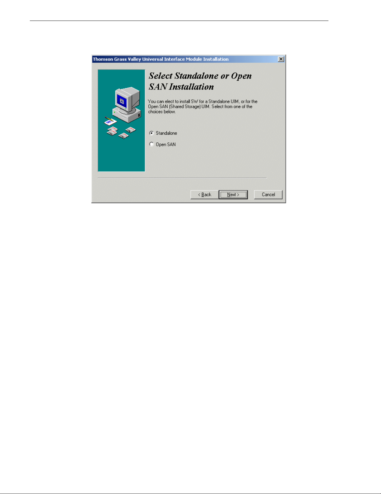
5. On the UIM Configuration page, select
Installation
option, then click Next and follow onscreen instruction s.
Start | Run and specifying the appropriate drive.).
IP Installation or SCSI (Open SAN)
Refer to “Install UIM-SAN-GEIP System Software for Open SAN” on page 54 for
instructions on the remaining screens for the Open SAN installation option.
February 5, 2008 UIM Instruction Man ual 21
Page 22
Chapter 1 Version 2.1.1 Release Information
6. When the UIM System Software installation process is complete, click Finish.
7. Proceed to “Part 2: Cr eate a syst em disk imag e file” of this procedure.
Part 2: Create a system disk image file
After updating UIM System Software, create a system disk image as described in
“Creating a system disk image” on page 126. This backup image can be used to
restore the system disk in the event of a severe software problem. The procedure
requires the Restore Program CD-ROM that you received with your UIM.
This completes the UIM system software installation proced ure.
Virus software support
Thomson Grass Valley does not recommend installing third party software on your
UIM. If you must install virus scanning software, configure it for manual virus scan
only. Automatic virus scanning could disrupt UIM opera ti on and shoul d not be used.
Performing critical Windo ws updates
From the factory, Automatic Windows Updates are disabled. This prevents updates
from being performed in a manner that c ould harm the ope ration of ne tworked UIMs.
Do not modi fy the Automatic Update s etting.
If your UIM has internet access, you can use the Windows operating system Update
feature to scan your UIM to d etermine if an y critical u pdates are req uired. Afterwa rd,
you can download and install those updates manually.
22 UIM Instruction Manual February 5, 2008
Page 23

CAUTION: Only critical Windows updates should be installed. Do not
!
install other Windows operating system or driver updates on your UIM
unless instructed by procedures in these release notes. “Critical” updates
must be installed manually using the Windows Update program.
To scan and install critical updates:
Performing critical Windows updates
1. In the Windows taskbar, click
Start, then Windows Update.
Internet Explorer opens and connects to the Windows update web site.
2. Click
Scan for updates. Wait for the scan t o complete.
3. If there are critical updates required for your UIM, follow the instructions on the
web page to install them.
February 5, 2008 UIM Instruction Man ual 23
Page 24

Chapter 1 Version 2.1.1 Release Information
Known problem s
The following limitations are present in this UIM System Software version 2.x.x. If
you wish to obtain more information about these limitations, please mention the
reference numbers that follow the description of each limitation. These known
problems will be resolve d in future rele ases.
Installation
Problem UIM software does not install, even though the previous versions of
UIM software was removed.
Workaround Delete the contents of the c:\profile directory. T he UIM inst allation
program tests for the presence of sp ecified files in that dire ctory.
UIM-Gigabit-IP Only
No known problems.
UIM-SAN-GEIP or UIM-SAN-FCIP Only
Problem Clips recorded with odd-numbered offset s are not corr ectly trans ferred.
(CR49254)
Workaround Clips must be recorde d with frame- based o ffset s wit h even values only.
Problem Drop-frame clips transf erred from NewsEdit systems report an incor rect
length on the Open SAN because the drop-fra me attribute is cha nged to
non-drop frame. (CR50021)
Workaround The clip transf ers i n its entirety, and th e duration of the material on the
Open SAN is correct, although it is incorrectly displayed.
Problem In the event of an FSM failover, clips that were queued to transfer in
Media Manager may not transfer after the failover. (CR42772)
Workaround Remove the transfer requests from Media Manager, then add them
again. Correct transfer operations resume about one minute after the
FSM failover event.
Problem Running Windows Disk Administrator while the UIM-SAN-GEIP or
UIM-SAN-FCIP
switch fabric may cause the Open SAN to fail. Windows Disk
Administrator may inadvertently relabel the disks in the O pen SAN.
Workaround Do not run Windows Disk Administrate, or disconnect the
UIM-SAN-GEIP or UIM-SAN-FCIP
while Windows Disk Administrator is in use.
is connected to the Open SAN Fibre Channel (SCSI)
from the Fibre Channel Switch
24 UIM Instruction Manual February 5, 2008
Page 25

UIM-SAN-GEIP or UIM-SAN-FCIP Only
Problem UIM fails to transfer some long GOP clips. (CR67074)
Workaround None. The problem occurs only for clips with an MPEG frame of less
than 512 bytes. Clips of this nature are rejected on import.
February 5, 2008 UIM Instruction Man ual 25
Page 26

Chapter 1 Version 2.1.1 Release Information
26 UIM Instruction Manual February 5, 2008
Page 27

Chapter 2
Product Description
This chapter includes:
• “Product overview”
• “Hardware platform configuration”
• “Software configurations available”
• “Ethernet redundancy”
February 5, 2008 UIM Instruction Man ual 27
Page 28

Chapter 2 Product Description
Product overview
The Grass Valley Universal Interface Module (UIM) provides a 1000BaseT Ethernet
network interface for streaming media file s in Profile stor age environments inc luding
standalone storage an d Open SAN shared st orage. UIM transf ers are compat ible with
other devices th at supp ort importing and exporting files using t he General Exchange
Format (GXF) as described in SMPTE 360M. The UIM system software design
makes the UIM transparent to the streaming devices.
The UIM can also provide additional Fibre Channel IP bandwidth in and out of an
existing Open SAN, allowing expansion of legacy Fibre Channel IP infrastructures
without the cost of converting to a different technology.
The UIM also supports MXF streaming f ormats based on the SMPTE 377M standard.
This allows the exchange of data between a variety of Grass Valley prod ucts and other
third party MXF-based production, editing, and stor age tools.
Hardware platform configuration
The UIM is implemented using a Dell Server running a Windows operating system
and UIM system software pre-i nstalled by Grass Valle y. Your Dell Server model may
be different than the one shown in the diagrams in this manual.
UIM hardware configuration
• Dell Server PC, dual power supply, mirrored system drive
• Four Ethernet NICs and a single Fibre Channel port; or
• Two Ethernet NICs and two Fibre Channel ports
• VGA monitor, mouse, and keyboard
The Ethernet NICs provi de the r edunda nt Ethe rnet c onnect io ns. Port s are confi gured
as two fault tolerant t eams for fai lover , two port s per te am. One te am named Con trol
Team is used to conn ect to the LAN used by Profil e storage for command and contr ol.
The other team, named Streaming Team, is used to connect to the 1000BT Ethernet
infrastructure for the streaming of media to other devices.
Some models of UIM re place the Gigabi t Ethern et strea ming te am with an a dditiona l
Fibre Channel port that i s used fo r stran ge transf ers over a Fibre Channel IP networ k.
This configuration is only supported when connected to an Open SAN.
28 UIM Instruction Manual February 5, 2008
Page 29
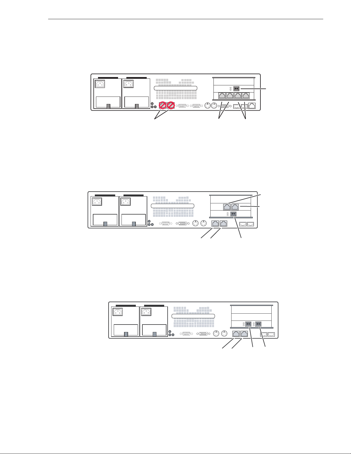
Rear panel view, Dell 2650
UIM
Rear panel view, Dell 2650
Fibre Channel
Network
Integrated
1000BT
Ports
(Not Used)
Control T eam
Intel Ports A/B
(Control LAN)
Rear panel view, Dell 2850, 1000 BaseT
UIM
B & A
Control T eam
Ports
(Control LAN)
Fibre Channel
Rear panel view, Dell 2850, Fibre Channel IP
Streaming Team
Intel Ports C/D
(Streaming LAN)
C
&
D
Port
Streaming Team
(Streaming LAN)
UIM
B & A
Control Team
Ports
(Control LAN)
February 5, 2008 UIM Instruction Man ual 29
IP & SCSI
Fibre Channel
Ports
Page 30
Chapter 2 Product Description
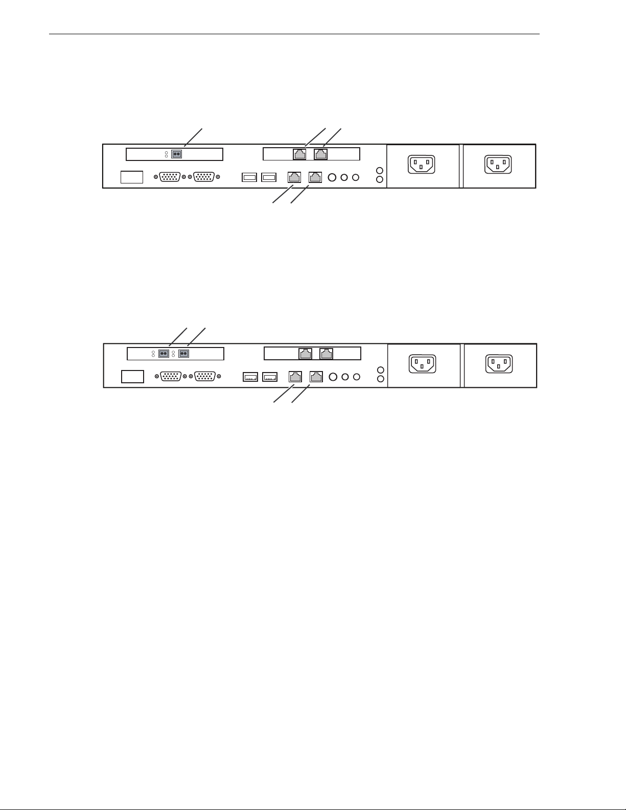
Rear panel view, Dell 1950, 1000 BaseT
UIM
Fibre Channel Port
A & B
Control Team
C & D
Streaming Team Ports
(Streaming LAN)
(Control LAN)
Ports
Rear panel view, Dell 1950, Fibre Channel IP
IP & SCSI
UIM
Fibre Channel Ports
A & B
Control Team
(Control LAN)
Ports
Software configurations available
There are three UIM conf igurations which share a common platform, but var y i n t he
installed cards and software:
• UIM-DIS-GEIP — configured for operation with standalone Profile storage
• UIM-SAN-GEIP — configured for integration into a Grass Valley Open SAN
shared storage system and provides Gigabit Ethernet streaming
• UIM-SAN-FCIP — configured for integration into a Grass Valley O pen SAN
shared storage system and provides Fibre Channel IP streaming
A UIM-SAN-GEIP is built as a UIM-SAN-GEIP, but requires additional software
installs an d setup for i ntegration in a Grass Valley Open SAN system. This is done
onsite or at the factory where the Open SAN shared storage system is assembled.
A UIM-SAN-FCIP is similar to a UIM-SAN-GEIP, with a extra Fibre Channel port
added, and the streaming Gigabit Ethernet ports removed.
The following sections describe each UIM product in more detail.
30 UIM Instruction Manual February 5, 2008
Page 31

UIM-DIS-GEIP des cript i on
The UIM-DIS-GEIP provides a 1000BT network interface for standalone Profile
storage. One UIM-DIS-GEIP is required for each standalone Profile system.
Connections are mad e via the Profile s ystem Fibre Channel Network Adapter (IP) an d
the Ethernet net work inte rface. The UIM should b e viewed a s a 2RU exte nsion to the
standalone Profile system. Transfers over the UIM appear seamless to applications.
The UIM-DIS-GEIP supports up to four concurrent transfers.
UIM-DIS-GEIP description
XP1
Fibre Channel
Cable
XP1_UIM
1000BT Ethernet LAN (Streaming)
10/100BT Ethernet LAN
XP2
Fibre Channel
Cable
XP2_UIM
XP3
XP3_UIM
WAN IP
Connection
10/100BT Ethernet LAN
XP4
Fibre Channel Switch Fabric
XP4_UIM
1000BT Ethernet LAN (Streaming)
The Fibre Channel connection t o the Profile can be made using a single cabl e (left side
of the previous diagram), or throu gh a Fibre Channel switch (right side of the previ ous
diagram). Using a switch to make the connection retains Fibre Channel network
transfer capability to other standalone Profile systems.
NOTE: The Profile Video Servers (PDR series) do not support the point to point
Fibre Channel connection.
UIM-SAN-GEIP description
The UIM-SAN-GEIP includes the additional software required to operate in an Open
SAN shared storage environmen t. The UIM-SAN-GEIP is connected as a client in the
Open SAN system and functions to provide a 1000BT network interface to shared
storage. One or more UIM-SAN-GEIPs are connected via the Fibre Channel (SCSI)
switch fabric and the command and control Ethernet switch fabric. Any number of
UIMs can be used depending on the number of simultaneous transfer streams
required. Each UIM-SAN-GEIP supports up to six concurrent transfers.
Each Profile XP Platform in the Open SAN is configured using host tables to proxy
to one fixed UIM. Automatic load balancing is not supported. Also, there is no
failover mechanism. If a UIM fails, meaning, if UIM1 fails, all Profiles that proxy to
UIM1 lose their 1000BT connection.
February 5, 2008 UIM Instruction Man ual 31
Page 32

Chapter 2 Product Description
Profile Open SAN Shared Storage
10/100BT Ethernet LAN (Control)
Shared Storage
SAN1_XP1
SAN1_FSM1
SAN1_FSM2
SAN1_XP2
SAN1_UIM1
Fibre Channel Switch Fabric (SCSI)
1000BT Ethernet LAN (Streaming)
UIM-SAN-FCIP description
The UIM-SAN-FCIP includes th e addition al softwar e require d to operat e in an Open
SAN shared storage envir onment. The UIM-SAN-FCIP i s connected as a clie nt in the
Open SAN system and functions to provide a Fibre Channel IP network interface to
shared storage. One or more UIM-SAN-FCIPs are connected via the Fibre Channel
(SCSI) switch fabric, the Fibre Channel IP switch fabric, and the command and
control Ethernet switch fabric. Any number of UIMs can be used depending on the
number of simultaneous transfer streams required. Both UIM-SAN-FCIPs and
UIM-SAN-GEIPs can be connected to the same Open SAN to provide both Gigabit
Ethernet and Fibre Channel IP st re ami ng capa bility. Each UIM-SAN-FCIP supports
up to six concurrent transfers.
SAN1_XP3
SAN1_XP4
SAN1_UIM2
Each Profile XP Platform in the Open SAN is configured using host tables to proxy
to one fixed UIM. Automatic load balancing is not supported. Also, there is no
failover mechanism. If a UIM fa ils, m eanin g, if UIM 1 fail s, all Pr ofil es that proxy to
UIM1 lose their Fibre Channel IP connection.
32 UIM Instruction Manual February 5, 2008
Page 33

Enable Fibre Channel network TCP checksums
Profile Open SAN Shared Storage
10/100BT Ethernet LAN (Control)
Shared Storage
SAN1_XP1
SAN1_XP2
SAN1_UIM1
SAN1_FSM1
SAN1_FSM2
SAN1_XP4
SAN1_UIM2
Fibre Channel Switch Fabric (SCSI)
Fibre Channel IP Network (Streaming)
SAN1_XP3
Enable Fibre Channel network TCP checksums
When configuring Profile XP Media Platform or Profile PDR Series Video Servers,
you must enable TCP checksums on the Fibre Channel Network adapter. For
instructions, refer to the Fibre Channel Networking chapter in the Profile XP Media
Platform System Guide or Profile Family User Manual.
February 5, 2008 UIM Instruction Man ual 33
Page 34

Chapter 2 Product Description
Ethernet redundancy
From the factory, the ports on the four port Ethernet adapt er are teamed using Adapter
Fault Tolerance (AFT) software provided by the network adapter vendor, such as
Intel. This provides automatic redundancy for the Ethernet connections. One AFT
team is dedicated to the command and control network connection in Profil e st ora ge
systems. The other is dedicated to streaming media transfers.
Adapter Fault Tolerance (AFT) is achieved by a team of two or more adapters
configured to provide a backup network connection. AFT teams have a primary
adapter and a backup, or secondary, adapter. During normal operation, only the
primary adapter trans mits traffi c. If the primary adapter or the link to the primary
adapter fails due to switc h, port, cable, or remote adapter failure the secondary adapt er
automatically takes over. For more information on fault tolerance, refer to the online
documentation provided with the teaming software configuration tool.
*Optional
One subnet can be
used with this connection.
10/100BT Ethernet LAN
10/100BT Ethernet LAN
XP1
Fibre Channel
Cable
x.x.201.x
XP1_UIM
1000BT Ethernet LAN (Streaming)
1000BT Ethernet LAN (Streaming)
XP2
Fibre Channel
XP2_UIM
NOTE: If you are using redundant net work connections, ensure that the Ethernet
switches used support Spanning Tree Protocol (STP), and that the protocol is
configured as described in “Redundant Ethernet network requirements” on
page 17.
x.x.100.x
Cable
x.x.202.x
x.x.100.x
x.x.200.x
x.x.200.x
IP*
Connection
WAN IP
Connection
10/100BT Ethernet LAN
10/100BT Ethernet LAN
XP3
Fibre Channel Switch Fabric
XP3_UIM
1000BT Ethernet LAN (Streaming)
1000BT Ethernet LAN (Streaming)
XP4
XP4_UIM
x.x.101.x
x.x.101.x
x.x.203.x
x.x.204.x
x.x.204.x
34 UIM Instruction Manual February 5, 2008
Page 35

Chapter 3
UIM-DIS-GEIP Installation: Standalone Profile Storage
Information in the chapter includes:
• “Are you redeploying Profile systems?”
• “Rack-mount the UIM-DIS-GEIP”
• “Specify host names for each UIM-DIS-GEIP”
• “Specify the subnets required”
• “Setup the master hosts file”
• “Connect network cables – Dell 2650”
• “Configure UIM-DIS-GEIP hostname and IP addresses”
• “Configure Profile host names & IP addresses”
• “Test the UIM-DIS-GEIP”
• “Create UIM-DIS-GEIP system disk image”
• “Solving common setup problems”
February 5, 2008 UIM Instruction Man ual 35
Page 36

Chapter 3 UIM-DIS-GEIP Installation: Standalone Profile Storage
Are you redeploying Profile systems?
Profile XP Media Platforms ordered from the factory for deployment with the
UIM-DIS-GEIP are ready to install and configure. However, if you are redepl oying
existing Profile syst ems for operation with the UIM-DIS- GEIP, you must perform the
procedures in Appendix A, Upgrading Existi ng Profile Syst ems for Depl oyment with
the UIM-DIS-GEIP on page 151. Afterward, return to this procedure and continue
with the following step, “Rack-mount the UIM-DIS-GEIP”.
Rack-mount the UIM-DIS-GEIP
Use the instructions in the Rack Installation Guide provided with the Dell Server
documentation set to mount the UIM-DIS-GEIP in a standar d 19 inch equipment rack.
You can also refer to the Del l Server Install ation and Troubleshoot ing Guide to make
power cord, mouse, keyboard, and monitor connections at this time.
Specify host names for each UIM-DIS-GEIP
When the UIM-DIS-GEIP is connected to a Profile system, the hostname for each
UIM-DIS-GEIP must follow a strict naming convention as shown:
XP1
Fibre Channel
Cable
XP1_UIM
1000BT Ethernet LAN (Streaming)
<ProfileXP hostname>
_UIM
As shown in the following diagram, if the UIM-DIS-GEIP is connected to a Profile
XP platform with hostname
XP1_UIM. Host names are not case sensitive.
10/100BT Ethernet LAN
XP2
Fibre Channel
Cable
XP2_UIM
XP1, the UIM-DIS-GEIP hostname must be set to
10/100BT Ethernet LAN
WAN IP
Connection
XP3
Fibre Channel Switch Fabric
XP3_UIM
1000BT Ethernet LAN (Streaming)
XP4
XP4_UIM
NOTE: The optional 10/100BT Ethernet connection is required for Pronet
connections between Profile media platforms only. This connection is used for
Profile API communication, such as that used by Media Manager.
36 UIM Instruction Manual February 5, 2008
Page 37

Specify the subnets required
Use the following rules to determine the subnets required for your network.
1. Specify a unique subnet for the Fibre Channel network as follows:
• Specify a subnet for each Profile XP to UIM-DIS-GEIP point-to-point
connection, that is, when a single cable is used as shown on the left side of the
diagram below.
• Specify a subnet f or t he Fibre Channel switch fabric when switches are used to
connect the Profile sys tem t o the UIM-DIS- GEIP as shown on the right side of
the diagram below.
NOTE: Profile PDR series products do not support the point-to-point connection.
2. Specify a subnet for the 1000BaseT Ethernet LAN (for streaming).
3. Specify a subnet for the Profile command and control Ethernet LAN.
The following diagrams illustrate these subnet requirements. Use these examples as a
models for specifying the subnets required for your system.
The following diagram il lustrates the subnets required. The diagrams also show two
ways of making the Profile to UIM- DIS-GEIP connection using eit her a point to point
connection (single cable), or a Fibre Channel switch. Note that Profile systems and
their UIMs have unique subne ts for their point to point Fibre Channel c onnections. As
shown, XP1 and XP2 and their corresponding UIMs have unique Fibre Channel IP
subnets, 192.168.201.xx and 192.168.20 2.xx. When a switch is use d to make the
Fibre Channel connect ion, one subnet may b e used. As shown, XP3 and XP4 and their
corresponding UIMs use the same Fibre Channel IP subnet, 192.168.203.xx.
Specify the subnets required
10/100BT Ethernet LAN
XP1
Fibre Channel
Cable
x.x.201.x
XP1_UIM
1000BT Ethernet LAN (Streaming)
XP2
Fibre Channel
XP2_UIM
x.x.100.x
Cable
x.x.202.x
x.x.200.x
IP*
WAN IP
Connection
Optional
With this connection, only one
subnet is required for the Profile XP
command and control Ethernet network.
10/100BT Ethernet LAN
XP3
Fibre Channel Switch Fabric
XP3_UIM
1000BT Ethernet LAN(Streaming)
x.x.101.x
XP4
XP4_UIM
x.x.203.x
x.x.204.x
February 5, 2008 UIM Instruction Man ual 37
Page 38

Chapter 3 UIM-DIS-GEIP Installation: Standalone Profile Storage
*Optional
One subnet can be
used with this connection.
10/100BT Ethernet LAN
10/100BT Ethernet LAN
XP1
Fibre Channel
Cable
x.x.201.x
XP1_UIM
1000BT Ethernet LAN (Streaming)
1000BT Ethernet LAN (Streaming)
XP2
Fibre Channel
XP2_UIM
NOTE: In redundant Ethernet network configurations, you must use Ethernet
switches that support Spanning Tree Protocol (STP). Refer to “Redundant Ethernet
network requirements” on page 17.
x.x.100.x
Cable
x.x.202.x
x.x.100.x
x.x.200.x
x.x.200.x
IP*
Connection
WAN IP
Connection
10/100BT Ethernet LAN
10/100BT Ethernet LAN
XP3
Fibre Channel Switch Fabric
XP3_UIM
1000BT Ethernet LAN (Streaming)
1000BT Ethernet LAN (Streaming)
XP4
XP4_UIM
x.x.101.x
x.x.101.x
x.x.203.x
x.x.204.x
x.x.204.x
Setup the master hosts file
Use the following steps to set up a master hosts file for all Profile platform s and
UIM-DIS-GEIPs. You must i nclude the names and IP address es of all Pro file systems
and UIM-DIS-GEIPs in the hosts file. This allows you to copy the sam e file to all
devices on the network instead of editing a unique hosts file on each machine.
On one of the UIM-DIS-GEIPs, create the hosts file as follows:
1. Power-on the UIM-DIS-GEIP and log on as Administrator (default password
triton).
2. Open the following file us ing Notepad— c:\winnt\system32\drivers\etc\hosts
3. Enter text in a single line for each network connect ion including all Profil e systems
and UIM-DIS-GEIPs. Be sure to include the local UIM-DIS-GEIP.
First type the IP address for a network interface, then use the TAB key or Spac e bar
to insert a few spaces. Now type the host name for that IP address, such as XP1.
You must add a suffix to the hos tname for ea ch high speed netw ork interfaces , e.g.
38 UIM Instruction Manual February 5, 2008
Page 39

Setup the master hosts file
Fibre Channel and 1000BT Ethernet, as shown in the following table.
Network Interface Hostname suffix
a
Example host file entry for
UIM hostname “XP1_UIM”
Control Team - Ports A & B None 192.168.100.101 XP1_UIM
Streaming Team - Ports C & D _he0 192.168.200.101 XP1_UIM_he0
Q-Logic FC NIC _fc0 192.168.201.101 XP1_UIM_fc0
a.
Suffix uses the zero character, not the letter ‘o’.
February 5, 2008 UIM Instruction Man ual 39
Page 40

Chapter 3 UIM-DIS-GEIP Installation: Standalone Profile Storage
Example hosts file
The following host file was created for the example networks shown on page 37
and page 38. Th is host f ile is used for both non-r edundant and redunda nt netw orks
since teamed network adapters share the same IP address. Use this example as a
model for creating your own host file.
192.168.100.101 XP1
192.168.201.101 XP1_fc0
192.168.100.111 XP1_UIM
192.168.201.111 XP1_UIM_fc0
192.168.200.111 XP1_he0 XP1_UIM_he0 # Streaming NIC of XP1_UIM
192.168.100.102 XP2
192.168.202.102 XP2_fc0
192.168.100.112 XP2_UIM
192.168.202.112 XP2_UIM_fc0
192.168.200.112 XP2_he0 XP2_UIM_he0 # Streaming NIC of XP2_UIM
192.168.101.103 XP3
192.168.203.103 XP3_fc0
192.168.101.113 XP3_UIM
192.168.203.113 XP3_UIM_fc0
192.168.204.113 XP3_he0 XP3_UIM_he0 # Streaming NIC of XP3_UIM
192.168.101.104 XP4
192.168.203.104 XP4_fc0
192.168.101.114 XP4_UIM
192.168.203.114 XP4_UIM_fc0
192.168.204.114 XP4_he0 XP4_UIM_he0 # Streaming NIC of XP4_UIM
Note that Profile systems and their corresponding UIMs have unique subnets for
their point to point Fibre Channel connecti ons. As shown, XP1 and XP2 and their
UIMs have unique Fibre Cha nnel IP subne ts, 192.168.201.x x and 192.168.202.x x.
When a switch is used to make the Fibre Channel connection, one subnet may be
used. As shown, XP3 and XP4 and t heir corresponding UIMs are on the same Fibre
Channel IP subnet, 192.168.203.xx. (Refer to “Specify the subnets required” on
page 37.)
Also notice that the IP address for the 1000BT connection used for streaming is
aliased to both the UIM-DIS- GEIP and the Profile XP host names.
For example:
192.168.200.101XP1_he0 XP1_UIM_he0 #Streaming NIC of XP1_UIM
4. Save the file and exit Notepad.
5. Copy this new master hosts file onto all Pro file syst ems and UIMs on t he ne twork.
NOTE: Errors in this configurat ion step wi ll render your media exchange network
inoperable. Take great care to enter all information correctly, then recheck for
errors.
40 UIM Instruction Manual February 5, 2008
Page 41

Connect network cables – Dell 2650
Connect network cables – Dell 2650
Connect the network cables f or each Prof ile XP Me dia Platfor m and UIM-DI S-GEIP
as shown.
Profile XP Media Platform
Dual-port Ethernet (opt.)
Port A*
*See note.
*NOTE: Redundant Ethernet Operation
1. Ensure that the primary and redundant ports are connected to different
switches.
2. Verify that the Ethernet switches support Spanning Tree Protocol
(STP), and that the protocol is configured as described in “Redundant
Ethernet network requirements” on page 17.
(Primary)
Port B*
(Redundant)
IP UIM
Slot location
may vary.
Integrated
1000BT
Ports
(Not Used)
Fibre Channel
Connection
(Point to point, or
Fibre Channel
Switch fabric)
Control T eam
Intel Ports A/B
(Control LAN)
100BT Ethernet
(Do not use when
dual-port Ethernet
option is installed.)
Streaming Teaming
Intel Ports C/D
(Streaming LAN)
February 5, 2008 UIM Instruction Man ual 41
Page 42

Chapter 3 UIM-DIS-GEIP Installation: Standalone Profile Storage
)
Connect network cables – Dell 2850
Connect the network cabl es for each Pro file XP Media Pla tform and Dell 2850- based
UIM-DIS-GEIP as shown.
UIM
Profile XP Media Platform
Control T eam
Intel Ports A/B
(Control LAN)
Streaming Teaming
Intel Ports C/D
(Streaming LAN)
CDAB
Fibre Channel
Connection
(Point to point, or
Fibre Channel
Switch fabric)
Dual-port Ethernet (opt.)
Port A*
*See note.
Ethernet Operation
1. Ensure that the primary and redundant ports are connected to different
42 UIM Instruction Manual February 5, 2008
(Primary)
Port B*
(Redundant)
Slot location
may vary.
*NOTE: Redundant
100BT Ethernet
(Do not use when
dual-port Ethernet
option is installed.
Page 43
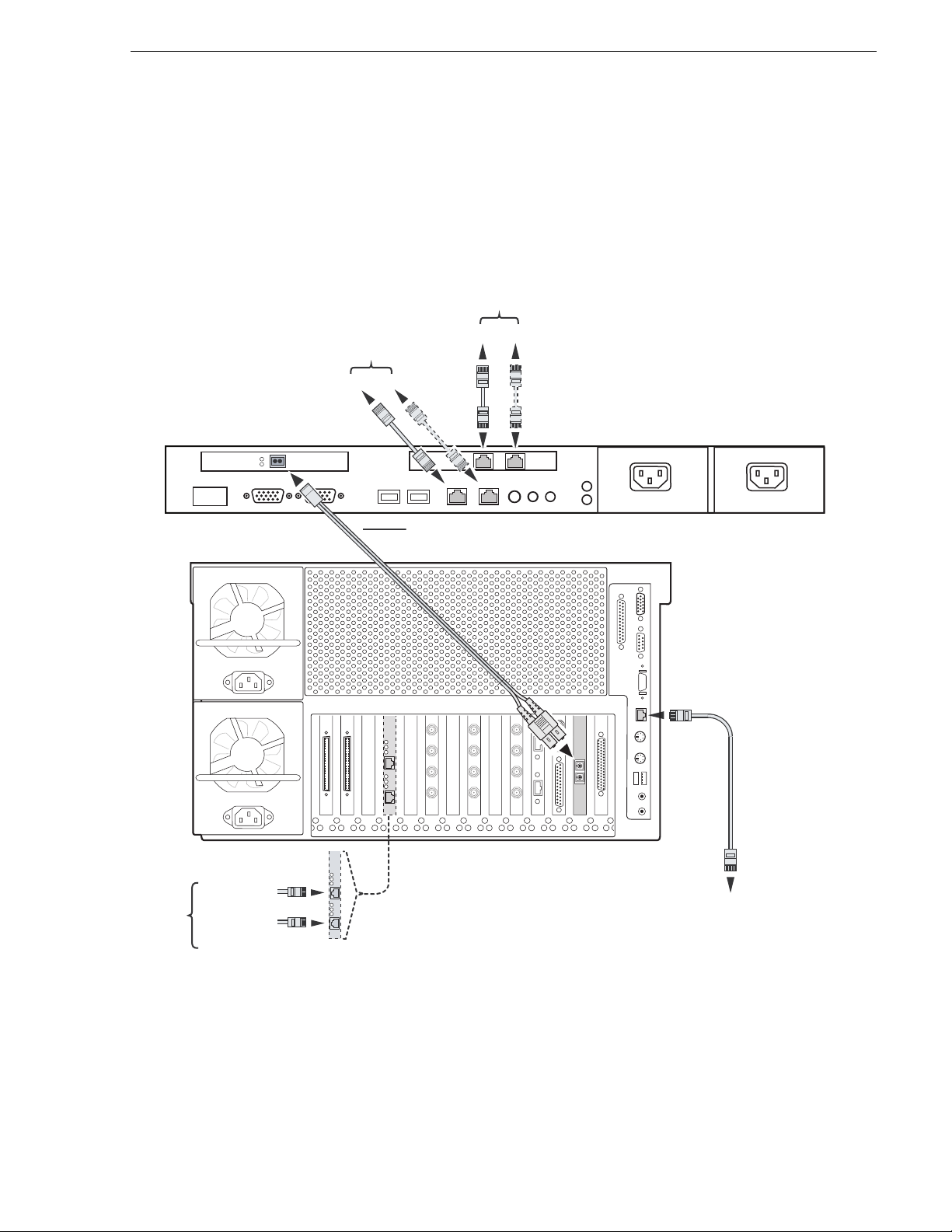
Connect network cables – Dell 1950
Connect network cables – Dell 1950
Connect the network cabl es for each Pro file XP Media Platf orm and Dell 1950- based
UIM-DIS-GEIP as shown.
Streaming Teaming
Ports C/D
(Streaming LAN)
Control T eam
Ports A/B
(Control LAN)
A
B
DC
Fibre Channel Connection
Profile XP Media Platform
Dual-port Ethernet (opt.)
Port A*
*See note.
*NOTE: Redundant Ethernet Operation
1. Ensure that the primary and redundant ports are connected to different switches.
2. Verify that the Ethernet switches support Spanning Tree Protocol (STP), and that the protocol is configured as described
in “Redundant Ethernet network requirements” on page 17.
(Primary)
Port B*
(Redundant)
Slot location
may vary.
(Point to point, or Fibre Channel Switch fabric)
100BT Ethernet
(Do not use when
dual-port Ethernet
option is installed.)
February 5, 2008 UIM Instruction Man ual 43
Page 44

Chapter 3 UIM-DIS-GEIP Installation: Standalone Profile Storage
Configure UIM-DIS-GEIP hostname and IP addresses
Refer to your system design and the requirements described in “Specify host names
for each UIM-DIS-GEIP” on pa ge 36 and “Specify the su bnets require d” on page 37,
then configure the hostname and IP addresses on each UIM-DIS-GEIP as follows.
1. Power-on the UIM-DIS-GEIP and log on as Administrator (default password:
triton).
2. Modify the UIM-DIS-GEIP hostname as follows:
a. Right-click the compu ter icon on th e deskto p, then selec t
Properties to open the
System Properties dialog box.
b. Click the
c. Enter the UIM-DIS-GEIP computer name, then click
d. Click
e. Click
f. Click
g. Click
Network Identification tab, then click Properties.
OK.
Yes to accept non-standard name.
OK to acknowledge the reboot mess age.
OK to close the System Properties dialog box.
NO. Do not reboot at this time.
3. Configure the IP address on each UIM-DIS-GEIP network adapter as follows:
a. Right-click the “My Network Places” desktop icon, then select
Properties to
open the Windows operating system “Network Connections” dialog box.
Depending on the Dell platform, ne twor k connections are displayed as follows:
Name Type Status Device Name
Dell 2650
QLogic FC NIC LAN Enabled QLogic QLA2X00 PCI Adapter
Intel 1000BT Port A LAN Enabled Intel(R) Pro/1000 MT Quad Port Server Adapter
Intel 1000BT Port B LAN Enabled Intel(R) Pro/1 000 MT Quad Port Server Adapter #2
Intel 1000BT Port C LAN Enabled Intel(R) Pro/1 000 MT Quad Port Server Adapter #3
Intel 1000BT Port D LAN Enabled Intel(R) Pro/1000 MT Quad Port Server Adapter #4
Control Team - Intel
Ports A/B
Streamin g T e am -
Intel Ports C/D
Dell 2850
QLogic FC NIC LAN Enabled QLogic QLA2X00 PCI Adapter
Intel 1000BT Port A LAN Enabled Intel(R) Pro/1000 MT Network Connecti on
Intel 1000BT Port B LAN Ena bled Intel(R) Pro/1000 MT Network Connection #2
Intel 1000BT Port C LAN Enabled Intel(R) Pro/1000 MT Dual Port Server Adapter
44 UIM Instruction Manual February 5, 2008
LAN Ena bled Intel(R) Advanced Network Serv ices Virtual Adapter
LAN Ena bled Intel(R) Advanced Network Serv ices Virtual Adapter #2
Page 45

Configure UIM-DIS-GEIP hostname and IP addresses
Name Type Status Device Name
Intel 1000BT Port D LAN Enabled Intel(R) Pro/1000 MT Dual Port Server Adapter #2
Control Team - Intel
Ports A/B
LAN Ena bled Intel(R) Advanced Network Serv ices Virtual Adapter
Streamin g T e am Intel Ports C/D
Dell 1950
QLogic FC NIC LAN Enabled QLogic QLA2X00 PCI Adapter
Broadcom 1000BT
Port A
Broadcom 1000BT
Port B
Control Team -
Broadcom Ports A
and B
Intel 1000BT Port C LAN Enabl e d TEAM: Streaming Team - Intel(R) Pro/1000 MT Dual
Intel 1000BT Port D LAN Enabled TEAM: Streaming Team - Intel(R) Pro/1000 M T Dual
Streamin g T e am Intel Ports C and D
LAN Ena bled Intel(R) Advanced Network Serv ices Virtual Adapter #2
LAN Enabled Broadcom BCM5708C NetXtreme II GigE (NDIS VBD
Client)
LAN Enabled Broadcom BCM5708C NetXtreme II GigE (NDIS VBD
Client) #2
LAN Enabled BASP Virtual Adapter
Port Server Adapter
Port Server Adapter #2
LAN Enabled TEAM: Streaming Team
b. Right-click one of the connection names as listed in the following table, then
select
Properties to configure network settings.
NOTE: Always configure the Ethe rnet network settings using the fault tolerance
teams. Do not select and configure the NIC adapters directly. In non-redundant
Ethernet configurations, the unused ports will be ignored.
Connection Name Listed Description Configuration Tasks
QLogic FC NIC Fibre Channel Network Adapter Configure the IP Address,
subnet mask, and othe r
a
Control Team - …Ports A & B Control LAN Team Members
Primary: …1000BT Port A
Secondary: …1000BT Port B
Streaming Team-…Ports C & D Streaming LAN Team Membersa.:
Primary: …1000BT Port C
Secondary: …1000BT Port D
a.
Primary designates the primary adapter for the team. Secondary designates the backup adapter. If the
primary connection is lo st, then re stored, it rejoin s the te am as a mem ber an d no t the prima ry co nnecti on.
When redundant con nections are not used, the unused port is igno red.
c. When prompted to restart, click
No. Wait until all connections are configured.
:
network settings f or each
connection as required by
your network design and
site requirements. (Refer to
“Specify the subnets
required” on page 37.)
Contact your local network
administrator of details.
February 5, 2008 UIM Instruction Man ual 45
Page 46

Chapter 3 UIM-DIS-GEIP Installation: Standalone Profile Storage
d. Repeat step b for the remaining team.
4. After all connections are configured, restart the U IM-DIS-GE IP.
5. Proceed to the next procedure, “Configure Profile host names & IP addresses”.
Configure Profile host names & IP addresses
On each Profile or Pr ofil e XP sys tem, use stand ard Wi ndows pr ocedur es to setup the
hostname and IP address for the Ethernet and Fibre Channel adapters. Refer to the
Profile XP System Guide or Profile Family Users Manual, and Windows NT 4.0
documentation for instructions.
NOTE: You must enable TCP checksums on the Fibre Channel Network adapter.
For instructions, refe r to the Fibre Channel Networking section in the Profile XP
System Guide or Profile Family Users Manual .
Test the UIM-DIS-GEIP
Stream a movie to/from the Profile XP Media Platform using FTP or a transfer
application like Profil e XP Media Manager. Refer to the Profi le XP Users Manual for
instructions on using Media Manager. Also refer to “If you have a problem:
UIM-DIS-GEIP” on page 112.
Create UIM-DIS-GEIP system disk image
After verifying proper UIM-DIS-GEIP in stallation, you shoul d create a backup image
of the system disk. You can use this disk image to restore the complete software on
the system disk, i ncl udi ng all the current system settings. This simplifies the process
of troubleshooting and correcting software faults.
To create a s ystem disk image, refer to “Creating a system disk image” on page 126.
Solving common setup problems
Refer to the following sections for help in solv ing some common setup problems.
Also refer to “If you have a problem: UIM-DIS-GEIP” on page 112.
Check the hosts file on each system
If you experience difficulty in completing the installation and getting the
UIM-DIS-GEIP running, the following checks might help locate the problem.
• Check Ethernet IP addresse s in the sys te m hosts fil e on each UIM-DI S-GEI P an d
each Profile system.
• Check Fibre Channel IP a ddress es in th e syst em hosts f ile on UI M-DIS-GEI P and
each Profile system.
• Check that Fibre Channel network adapter TCP/IP checksums are enabled on the
Profile systems. For instructions, refer to the Fibre Channel Networking section in
the Profile XP System Guide or Profile Family Users Manual.
46 UIM Instruction Manual February 5, 2008
Page 47

Testing Ethernet connectivity and name resolution
Testing Ethernet connectivity and name resolution
Test Ethernet connectivity and name resolution using host names and the ping
command in the Windows command prompt on the UIM-DIS-GEIP.
For example, type:
ping XP1 <RETURN>
If this returns:
Pinging XP1 [192.168.100.101]
you have successfully resolved the name “XP1” to the IP address
[192.168.100.101]
If not, you may want to reboot to ensure host file and network settings are in effect,
or recheck your spelling in the hosts file.
If the host does not reply to t he ping, chec k network setti ngs on the t arget syste m, and
cable connections.
Test Fibre Channel network name resolution
Test connectivity and name resolution using the ping command in the Windows
command prompt.
For example:
ping XP1_fc0 <RETURN>
If this returns:
Pinging XP1_fc0 [192.168.201.101]
you have successfully resolved the name “XP1_fc0” to the IP address
192.168.201.101]
If the above ping returns:
Bad IP Address XP1_fc0
the Fibre Channel IP add ress is n ot resolv ed. If not, you ma y need to re boot to en sure
changes ta ke effect, or check again for spelling errors in the hosts file.
Check Profile (PDR Family) Fibre Channel network settings
Use the fcconfig commands at the Windows command prompt to verify Fibre
Channel network settings on all Profile PDR family platforms. Commands are
described in the Profile Family Users Manual. Refer to Appendix A, Upgrading
Existing Profile Systems for Deployment with the UIM-DIS-GEIP on page 151 for
correct settings.
For example:
• On each Profile system, type
fcconfig to check the Fibre Channel network
settings.
• Verify that
fcping -all runs and all Profile hosts can be resolved by name.
NOTE: The IP UIM will not respond to fcping.
February 5, 2008 UIM Instruction Man ual 47
Page 48

Chapter 3 UIM-DIS-GEIP Installation: Standalone Profile Storage
• Check the fcconfig setting for the hardware address on each Profile system. Each
hardware address must be unique.
If all routes are set up correctly and you still fail to stream between Profile systems
using the Media Manager, try the following:
• Ensure that portmap and chgsrvr are running on the Profile system (should be in
pdrstart.bat).
Check Profile XP (PVS) Fibre Channel network setti ngs
Open Configuration Manager, then select Network to verify Fibre Channel network
settings on Profile XP PVS seri es platforms. Refer to the Profile XP System Guide for
information setting network settings using Configuration Manager.
Refer to “If you have a problem: UIM-DIS-GEIP” on page 112 for more
troubleshooting procedures.
48 UIM Instruction Manual February 5, 2008
Page 49

Chapter 4
UIM-SAN-GEIP Installation: Grass Valley Open SAN System
This chapter describes how to install the UIM-SAN-GEIP in the Grass Valley Open
SAN Shared Storage system. The UIM-SAN-GEIP provides a 1000BaseT Ethernet
network interface to the Open SAN shared storage for media transfers.
Procedure summary:
• “Onsite planning”
• “Rack-mount the UIM”
• “Converting the UIM-DIS-GEIP to a UIM-SAN-GEIP”
• “Modify the master hosts file”
• “Configure the UIM network settings”
• “Connect UIM-SAN-GEIP network cables Dell 2650”
• “Install CVFS client software on the UIM-SAN-GEIP”
• “Perform miscellaneous system settings”
• “Enable Fibre Channel network TCP checksums”
• “Verify access to shared storage”
• “Test the UIM-SAN-GE IP functiona lity”
• “Create UIM-SAN-GEIP system disk image”
February 5, 2008 UIM Instruction Man ual 49
Page 50

Chapter 4 UIM-SAN-GEIP Installation: Grass Valley Open SAN System
Onsite planning
Use the following sections to plan the deployment of the UIM-SAN-GEIP in the
Grass Valley Open SAN Shared Storage system.
!
CAUTION: Do not connect the UIM-SAN-GEI P to the Fibre Channel
SCSI fabric until after you have performed “Uninstall the Fibre
Channel adapter IP dri ver” on page 53. The IP driver will cause Open
SAN record and playout to fail.
Specify host names in the Open SAN
When deploying the UIM-SAN-GEIP in an Open SAN Shared Storage system, you
must follow a strict host naming convention wi thin the Open SAN for clie nt
machines, including the UIM-SAN-GEIP. You must use a common prefix to name
each client machine, as shown below:
[common prefix]_ [client hostname]
For example, you could i denti fy the Ope n SAN sys tem as SAN1; you would then use
SAN1 as a prefix to name all the client machines in the shared storage system—
SAN1_XP1, SAN1_XP2, and so on. The n aming conven tion does not need to appl y to
the FSM host name, but it can for consistency.
The following diagram illustrates the naming convention. Use this as a model for
specifying host names in your Open SAN Shared Storage system.
Profile Open SAN Shared Storage
10/100BT Ethernet LAN (Control)
SAN1_XP1
SAN1_XP2
SAN1_UIM1
Shared Storage
SAN1_FSM1
SAN1_XP3
SAN1_FSM2
SAN1_XP4
SAN1_UIM2
Fibre Channel Switch Fabric (SCSI)
1000BT Ethernet LAN (Streaming)
50 UIM Instruction Manual February 5, 2008
Page 51

Specify a subnet address for the 1000BT streaming LAN
6
e
x
XP6
e
n
05.xx.2
WAN
XP5
NOTE: Host names are limited to 15 characters. Also, host names are not case
sensitive.
Specify a subnet address for the 1000BT streaming LAN
You must specify a unique subnet address for the 1000BT LAN used for streaming
media. Do not use the sa me subnet addres s as the control LAN. Check with your l ocal
network administrator to obtain a valid subnet address.
The following diagram illustrates the subnet address requirements.
Profile Open SAN Shared Storage
10/100BT Ethernet LAN (Control) x.x.100.x
Shared Storage
[1]
SAN1_XP1
SAN1_XP2
SAN1_UIM1
1000BT Ethernet LAN (Streaming) x.x.200.x
Notes:
[1] Optional redundant Ethernet
fabrics, and Fibre Channel switch
fabrics are not shown.
[2] The number of UIM-SAN-GEIPs is
determined by the number of
simultaneous streams and the
performance required.
[3] To install UIM-DIS-GEIPs with
standalone Profile platforms, refer to
Chapter 3, UIM-DIS-GEIP
Installation: Standalone Profile
Storage on page 35.
SAN1_FSM1
SAN1_FSM2
[2]
Fibre Channel Switch Fabric (SCSI)
[1]
Profile XP
Platform
(Standalone)
[3]
ha
SAN1_XP3
SAN1_XP4
[2]
SAN1_UIM2
[1]
WAN
1000BT Ethernet x.x.204.x
Connection
XP
r
nel
Profile XP
Platform
(Remote/
Standalone)
ibr
[3]
onnection
February 5, 2008 UIM Instruction Man ual 51
Page 52

Chapter 4 UIM-SAN-GEIP Installation: Grass Valley Open SAN System
Specify redundant FC SCSI switch fabric topology
In failover-configured Open SANs that have redundant Fibre Channel SCSI fabrics,
the fabric topology must be configured in a particular way to assure correct failover
performance. This topology is often custom-specified for individual Open SANs; as
appropriate, this specification should be sought and followed.
In general, given redundant SCSI fabrics A and B, follow this fabric topology:
• The A ports for all Profile XP systems and RAID chassis are connected to the A
fabric domain.
• The B ports for all Profile XP systems and RAID chassis are connected to the B
fabric domain.
• The UIM-SAN-GEIPs do not have redundant Fibre Channel SCSI ports. You
should split the attachment of multiple UIM-SAN-GEIPs between the A and B
domains.
• Domain numbers are assigned to each Fibre Channel switch such that any
A-domain value is less than any B-domain value.
This topology provides the following failover behavior:
• Each Fibre Channel client, including the UIM-SAN-GEIPs, will discover in
order the A, then B RAID controllers.
• The UIM-SAN-GEIPs will select a single, stable, predictable path to the
redundant RAID controllers.
• In the event of a RAID controller fai lur e, a UIM-S AN-GEIP, after rebooting if
necessary, will find the alternate path to the RAI D chassis.
• In the event of a Fibre Channel switch failure, the UIM-SAN-GEIP not
primarily connected to the failed switch wi ll continue to functi on, though it may
first require rebooting.
Rack-mount the UIM
Use the instructions in the Rack Installation Guide provided with the Dell Server
documentation set to mount the UIM in a stan dar d 19 inc h equi pment ra ck. You can
also refer to the Dell Server Installation and Troubleshooting Guide to make power
cord, mouse, keyboard, and monitor connections at this time. Do not make network
connections at this time.
!
CAUTION: Do not connect Fibre Channel connection at this time.
Refer to “Uninstall the Fibre Channel adapter IP driver” on page 53.
52 UIM Instruction Manual February 5, 2008
Page 53

Converting the UIM-DIS-GEIP to a UIM-SAN-GEIP
Converting the UIM-DIS-GEIP to a UIM-SAN-GEIP
In most cases, UIM-SAN-GEIPs shipped from the factory are pre-configured for
operation in an Open SAN environm ent. You sh ould verify that all the f ollowing
procedures have been accomplished, and perform any steps that are site-specific.
If you must convert the UIM-DIS-GEIP to a UIM-SAN-GEIP for deployment in an
Open SAN s hared storage system , perform a ll the proce dures in th e following
sections.
Uninstall the Fibre Channel adapter IP driver
The Fibre Channel adapter I P driver must be uninstal led prior to connecting the UIM
to the Open SAN SCSI Fi bre Channel switch fabric.
To uninstall the Fibre Channel adapter IP driver:
1. Power on the UIM and log on as administrator (default password: triton).
2. Right-click the My Computer desktop icon, then select
The Computer Management application is displayed.
3. Click on
4. Expand
5. Right-click the Fibre Channel Adapter de vice, i.e. QLogic QLA2X00 PCI Adapter,
then select
6. Accept the warning.
7. When uninstall is complete, restart the UIM.
NOTE: Now it is safe to connect the UIM-SAN-GEIP to the appropriate Fibre
Channel switch.
8. Proceed with “Install UIM-SAN-GEIP System Software for Open SAN”.
Device Manager.
Network Adapters icon in the right hand pane.
Uninstall.
Manage.
February 5, 2008 UIM Instruction Man ual 53
Page 54

Chapter 4 UIM-SAN-GEIP Installation: Grass Valley Open SAN System
Install UIM-SAN-GEIP System Software for Open SAN
To install the Open SAN version of UIM System Software:
1. Power on the UIM and log on as administrator (password: triton).
2. In stall software as instructed in “Installing UIM System Software” on page 21,
except as fo llows:
a. On the UIM Configuration dialog box, select
option.
SCSI (Open SAN) Installation
54 UIM Instruction Manual February 5, 2008
Page 55

Install UIM-SAN-GEIP System Software for Open SAN
b. Enter the names of File System Managers on your Open SAN.
NOTE: If your Open SAN uses PFR700 RAIDs, be sure to check the option in this
dialog box. If not, clear the check box.
3. Click
4. Wh en installation is comple te, click
Next and follow the on-screen prompts to complete the installation.
Finish.
5. Continue with the next procedure “Modify the master hosts file”.
February 5, 2008 UIM Instruction Man ual 55
Page 56

Chapter 4 UIM-SAN-GEIP Installation: Grass Valley Open SAN System
Modify the master hosts file
Use the following steps to modify the master hosts file. The master hosts file is
maintained and copied to al l networked devices in the Open SAN Shared Storage
system as well as other Profiles and UIMs in the facility and is used for name
resolution. In this procedu re, you’ll add the IP addresses and host names for all UIMs.
After modifying th e master hosts fil e, you must copy it to all network ed devices in t he
Open SAN sys tem, as well as other Profile platforms and UIMs in the facility.
If you are deploying a UIM-SAN-GEIP in an existing Open SAN system, you may
have to modify all Profile XP platform host names to meet the host naming
requirements descri bed in “Spec ify ho st names in the Open SAN” on page 50. If this
is the case, you also need t o modify the Profile XP hostname entries in the master host
file.
About UIM-SAN-GEIP host name aliasing
Host name aliasing in the hosts file is used to assign the UIM-SAN-GEIP as the
1000BT stre aming interface for the P rofile XP platforms in t he Open SAN system.
Aliasing is accomplished in the hosts file by assigning multiple host names to the
same IP address, in this case, the UIM-SAN-GEIP network interface IP addresses. To
assign the UIM-SAN-GEIP as the 1000BT interface, alias es for each Profile pl atform
in the Open SAN must be added using a strict naming convention as shown below.
Referring to the example Open SAN system on page 57, you would add the followi ng
entries to th e master hosts file:
192.168.100.157 SAN1_UIM1 SAN1_XP1_UIM SAN1_XP2_UIM
192.168.200.157 SAN1_UIM1_he0 SAN1_XP1_he0 SAN1_XP2_he0
From this example, you can see that the UIM-SAN-GEIP control LAN network
interface mapped to the UIM hostname SAN1_UIM 1 is also known by the aliases
SAN1_XP1_UIM, and SAN1_XP2_UIM. Also, t he UIM-SAN- GEIP st r eaming LAN
network interface mapped to SAN1_UIM1_he0 is also known by its aliases
SAN1_XP1_he0, and SAN1_XP2_he0. (Refer to “Specify host names in the Open
SAN” on page 50 for an explanation of the “_he0” suffix.) With these settings,
SAN1_XP1 and SAN1_XP2 will both proxy their transfer requests to SAN1_UIM1.
56 UIM Instruction Manual February 5, 2008
Page 57

About load balancing when multiple UIM-SAN-GEIPs are used
Profile Open SAN Shared Storage
10/100BT Ethernet LAN (Control) x.x.100.x
Shared Storage
SAN1_XP1
SAN1_XP2
SAN1_UIM1
Fibre Channel Switch Fabric (SCSI)
1000BT Ethernet LAN (Streaming) x.x.200.x
SAN1_FSM1
SAN1_FSM2
About load balancing when multiple UIM-SAN-GEIPs are used
There can be multiple UIM-SAN-GEIPs deployed in an Open SAN Shared Storage
system. The number of UIM-SAN-GEIPs ne eded is determined by a combination of
the following requirem ents: the number of sim ultaneous transfer streams; transfer
performance.
When multiple UIM-SAN-GEIPs are used, host name aliasing is used in the hosts file
to assign the UIM-SAN-GEIPs to the Profile XP platforms in the Open SAN for
proper load balancing. Referring to the example system on page 51, SAN1_UIM1
handles transfer req uests for Profil es SAN1_XP1 and SAN1_XP2 while SAN1_UIM2
handles transfer requests for SAN1_XP3 and SAN1_XP4. To accomplish this, th e
following entries ar e added to the master host file.
192.168.100.157 SAN1_UIM1 SAN1_XP1_UIM SAN1_XP2_UIM
192.168.100.158 SAN1_UIM2 SAN1_XP3_UIM SAN1_XP4_UIM
192.168.200.157 SAN1_UIM1_he0 SAN1_XP1_he0 SAN1_XP2_he0
192.168.200.158 SAN1_UIM2_he0 SAN1_XP3_he0 SAN1_XP4_he0
NOTE: Multiple UIM-SAN-GEIPs do not prov ide aut omatic fai lover capabi lity . If
a UIM-SAN-GEIP becomes unavailable, transfer requests will fail for all Profile
platforms assigned to it.
February 5, 2008 UIM Instruction Man ual 57
Page 58

Chapter 4 UIM-SAN-GEIP Installation: Grass Valley Open SAN System
Entries
Example master hosts file entries for the UIM-SAN-GEIP
The following master host file was cr eated for the exampl e Open SAN system shown
on page 51. This host file can be used for both non-redun dant and r edundant ne twork
scenarios since teamed network adapters share the same IP address. You can use the
following example as a model for creating your own host file.
192.168.100.151 SAN1_XP1
192.168.100.152 SAN1_XP2
192.168.100.153 SAN1_XP3
192.168.100.154 SAN1_XP4
192.168.100.155 SAN1_FSM1
192.168.100.156 SAN1_FSM2
192.168.100.157 SAN1_UIM1 SAN1_XP1_UIM SAN1_XP2_UIM
192.168.100.158 SAN1_UIM2 SAN1_XP3_UIM SAN1_XP4_UIM
192.168.200.157 SAN1_UIM1_he0 SAN1_XP1_he0 SAN1_XP2_he0
192.168.200.158 SAN1_UIM2_he0 SAN1_XP3_he0 SAN1_XP4_he0
192.168.100.105 XP5
192.168.205.105 XP5_fc0
192.168.100.115 XP5_UIM
192.168.205.115 XP5_UIM_fc0
192.168.200.115 XP5_he0 XP5_UIM_he0 #Streaming NIC of XP5_UIM
128.181.104.106 XP6
128.181.206.106 XP6_fc0
128.181.104.116 XP6_UIM
128.181.206.116 XP6_UIM_fc0
128.181.204.116 XP6_he0 XP6_UIM_he0 #Streaming NIC of XP6_UIM
100BT
Entries
UIMGigabit-
SCSI
Entries
Standalone
Profile XP
Systems
Example master hosts file entries for two SANs
The following master host file was creat ed for the example s ystem shown on page 59.
This host file can be used for both non-redundant and redundant network scenarios
since teamed network adapters share the same IP address.
192.168.100.151 SAN1_XP1
192.168.100.152 SAN1_XP2
192.168.100.155 SAN1_FSM1
192.168.100.156 SAN1_FSM2
192.168.100.051 SAN2_XP1
192.168.100.052 SAN2_XP2
192.168.100.055 SAN2_FSM1
192.168.100.056 SAN2_FSM2
192.168.100.157 SAN1_UIM1 SAN1_XP1_UIM SAN1_XP2_UIM
192.168.100.057 SAN2_UIM1 SAN2_XP1_UIM SAN2_XP2_UIM
192.168.200.157 SAN1_UIM1_he0 SAN1_XP1_he0 SAN1_XP2_he0
192.168.200.057 SAN2_UIM1_he0 SAN2_XP1_he0 SAN2_XP2_he0
192.168.100.105 XP5
192.168.205.105 XP5_fc0
192.168.100.115 XP5_UIM
192.168.205.115 XP5_UIM_fc0
192.168.200.115 XP5_he0 XP5_UIM_he0 #Streaming NIC of XP5_UIM
128.181.104.106 XP6
128.181.206.106 XP6_fc0
128.181.104.116 XP6_UIM
128.181.206.116 XP6_UIM_fc0
128.181.204.116 XP6_he0 XP6_UIM_he0 #Streaming NIC of XP6_UIM
100BT
Entries
UIMGigabit-
SCSI
Standalone
Profile XP
Systems
58 UIM Instruction Manual February 5, 2008
Page 59

Example master hosts file entries for two SANs
LAN
x
00BT Eth
LAN
x
SAN1_XP1
SAN1_XP2
SAN1_UIM1
Fibre Channel Switch Fabric (SCSI)
Notes:
[1] To install UIM-SAN-GEIPs with
standalone Profile platforms, see
Chapter 3, UIM-DIS-GEIP
Installation: Standalone Profile
Storage on page 35.
[2] Optional redundant Ethernet
fabrics, and Fibre Channel switch
fabrics are not shown.
SAN1
10/100BT Ethernet LAN (Control) x.x.100.x
Shared Storage
SAN1_FSM1
SAN1_FSM2
1000BT Ethernet LAN (Streaming) x.x.200.x
[1]
Profile XP
Platform
(Standalone)
Ethernet
x.x.100.
SAN2_XP1
SAN2_XP2
onnection
SAN2
Shared Storage
SAN2_UIM1
Fibre Channel Switch Fabric (SCSI)
WAN
Connection
1000BT Ethernet LAN x.x.204.x
1
ernet
SAN2_FSM1
SAN2_FSM2
x.x.104.
To modify the FSM master hosts file:
1. On the FSM, make a copy of the master hosts and name it hosts.bak. The host s file
is located at c:\winnt\system32\drivers\etc\hosts.
This copy can be used to recover the original file if there is a problem.
2. Open the hosts file at c:\winnt\system32\drivers\etc\hosts using Notepad or some
other text editor.
3. Use the following steps to t ype the entry for the UIM-SAN-GEIP networ k interface
connected to the control LAN.
a. On a single line , e nte r the IP address for the network in te rf ac e connected to the
control LAN.
b. In sert a few spa ces, then type the UIM-S AN-GEIP host name follow ed by the
_UIM1 suffix.
For example:
192.168.100.157 SAN1_UIM1
c. Insert a few more spaces, then type all Profile platform host names assigned to
this UIM-SAN-GEIP. Use the Profile host nam e followed by the _UIM suffix.
February 5, 2008 UIM Instruction Man ual 59
Page 60

Chapter 4 UIM-SAN-GEIP Installation: Grass Valley Open SAN System
For example:
192.168.100.157 SAN1_UIM1 SAN1_XP1_UIM SAN1_XP2_UIM
4. Use the following steps to type the entry for the UIM-SAN-GEIP 1000BT
streaming network interface
a. On a single line , e nte r the IP address for the network interface connected to the
streaming LAN.
b. In sert a few spa ces, then type the UIM-S AN-GEIP host name follow ed by the
_he0 suffix. (NOTE: The suffix uses the zero character, not the letter ‘o’.)
For example:
192.168.200.157 SAN1_UIM1_he0
c. Insert a few more spa ces, then type all Profile platform ho st names assigned to
this UIM-SAN-GEIP. Use the Profile host nam e followed by the _he0 suffix.
For example:
192.168.200.157 SAN1_UIM1_he0 SAN1_XP1_he0 SAN1_XP2_he0
5. If you modified the Profile XP platform host names as described in “Specify host
names in the Open SAN” on pag e 50, you must revise t hose e ntrie s in the ho st fi le
now.
6. Save the master hosts file and exit Notepad.
7. Copy the new master hosts file to all network devices in the Open SAN system
including FSMs, Profile XP platforms, other UIM-SAN-GEIPs, and standalone
Profile platforms in the facility that proxy to the UIM.
c:\winnt\system32\drivers\etc\hosts
NOTE: Errors in this configurat ion step wi ll render your media exchange network
inoperable. Take great care to enter all information correctly, then recheck for
errors.
60 UIM Instruction Manual February 5, 2008
Page 61

Configure the UIM network settings
Configure the UIM network settings
Refer to your system design and the requirements described in “Specify host names
in the Open SAN” on page 50 and “Specify a subnet address for the 1000BT
streaming LAN” on page 51, then configure network settings on each
UIM-SAN-GEIP.
1. Power-on the UIM-SAN-GEIP and log on as Administrator (default password:
triton).
2. Modify the UIM-SAN-GEIP host name as follows:
a. Right-click the comput er icon on th e deskto p, then selec t
Properties to open the
System Properties dialog box.
b. Click the
c. Enter the UIM-SAN-GEIP comp uter name, then click
d. Click
e. Click
f. Click
g. Click
Network Identification tab, then click Properties.
OK.
Yes to accept non-standard name.
OK to acknowledge the reboot message.
OK to close the System Properties dialog box.
NO. Do not reboot at this time.
3. Configure the TCP/IP settings on each UIM-SAN-GEIP network adapter as
follows:
a. Right-click the “My Network Places” desktop icon, then select
Properties to
open the Windows operating system “Network Connections” dialog box.
Depending on the Dell platfo rm, net work connections are displayed as follows:
Name Type Status Device Name
Dell 2650
QLogic FC NIC LAN Enabled QLogic QLA2X00 PCI Adapter
Intel 1000BT Port A LAN Enabled Intel(R) Pro/1000 MT Quad Port Server Adapter
Intel 1000BT Port B LAN Enabled Intel(R) Pro/1 000 MT Quad Port Server Adapter #2
Intel 1000BT Port C LAN Enabled Intel(R) Pro/1 000 MT Quad Port Server Adapter #3
Intel 1000BT Port D LAN Enabled Intel(R) Pro/1000 MT Quad Port Server Adapter #4
Control Team - Intel
Ports A/B
Streamin g T e am -
Intel Ports C/D
Dell 2850
QLogic FC NIC LAN Enabled QLogic QLA2X00 PCI Adapter
Intel 1000BT Port A LAN Enabled Intel(R) Pro/1000 MT Network Connecti on
Intel 1000BT Port B LAN Ena bled Intel(R) Pro/1000 MT Network Connection #2
February 5, 2008 UIM Instruction Man ual 61
LAN Ena bled Intel(R) Advanced Network Serv ices Virtual Adapter
LAN Ena bled Intel(R) Advanced Network Serv ices Virtual Adapter #2
Page 62

Chapter 4 UIM-SAN-GEIP Installation: Grass Valley Open SAN System
Name Type Status Device Name
Intel 1000BT Port C LAN Enabled Intel(R) Pro/1000 MT Dual Port Server Adapter
Intel 1000BT Port D LAN Enabled Intel(R) Pro/1000 MT Dual Port Server Adapter #2
Control Team - Intel
Ports A/B
Streamin g T e am -
Intel Ports C/D
Dell 1950
QLogic FC NIC LAN Enabled QLogic QLA2X00 PCI Adapter
Broadcom 1000BT
Port A
Broadcom 1000BT
Port B
Control Team -
Broadcom Ports A
and B
Intel 1000BT Port C LAN Enabl e d TEAM: Streaming Team - Intel(R) Pro/1000 MT Dual
Intel 1000BT Port D LAN Enabled TEAM: Streaming Team - Intel(R) Pro/1000 M T Dual
Streamin g T e am Intel Ports C and D
LAN Ena bled Intel(R) Advanced Network Serv ices Virtual Adapter
LAN Ena bled Intel(R) Advanced Network Serv ices Virtual Adapter #2
LAN Enabled Broadcom BCM5708C NetXtreme II GigE (NDIS VBD
Client)
LAN Enabled Broadcom BCM5708C NetXtreme II GigE (NDIS VBD
Client) #2
LAN Enabled BASP Virtual Adapter
Port Server Adapter
Port Server Adapter #2
LAN Enabled TEAM: Streaming Team
b. Right-click either fault tolerance team, Control Team - … Ports A & B, or
Streaming Team - … Ports C & D, then select
Properties to configure network
settings. Team descriptions are shown in the table that follows.
NOTE: Al ways configure the Ethernet network settings using the fault tolerance
teams. Do not select and co nfigure the network adapters directly. In non-redund ant
Ethernet configurations, the unused ports will be ignored.
Connection Name Listed Description Configuration Tasks
Control Team1 - … Ports A & B Control LAN Team Membersa:
Primary: … 1000BT Port A
Secondary: … 1000BT Port B
Streaming Team - … Ports C & D Streaming LAN Team Members
Primary: … 1000BT Port C
Secondary: … 1000BT Port D
Configure the IP Address,
subnet mask, and other
network settings for each
connection as required by
a.
:
your network design and site
requirements. (Refer to
“Specify a subnet address for
the 1000BT streaming LAN”
on page 51.) Contact your
local network admi nistrator
of details.
62 UIM Instruction Manual February 5, 2008
Page 63

Configure the UIM network settings
a.
Primary designates the primary adapter for the team. Secondary designates the backup adapter. If the
primary connection is lost, then restored, it rejoins the team as a member and not the primary connection.
When redundant con nections are not used, the unused port is igno red.
c. When prompted to restart, click No. Wait until all connections are configured.
d. Repeat step b for the remaining team.
4. Af ter all connections are configured , restart the UIM-SAN-GEIP.
5. Proceed to the next procedure “Connect UIM-SAN-GEIP network cables Dell
2650”.
February 5, 2008 UIM Instruction Man ual 63
Page 64

Chapter 4 UIM-SAN-GEIP Installation: Grass Valley Open SAN System
Connect UIM-SAN-GEIP network cables Dell 2650
Connect the network cables for each UIM-SAN-GEIP as shown. Be sure to consult
your Ethernet and Fibre Channel switch fabric designs as you make connections.
Refer to “Onsite planning” on page 50.
Fibre Channel
Connection
To Fibre Channel
Switch (SCSI)
CAUTION: Do not connect the
UIM-SAN-GEIP to the Fibre Channel switch
!
fabric until after you have performed “Uninstall
the Fibre Channel ad apter IP driver” on
page 53. The IP driver will cause Open SAN
record and playout to fail.
SCSI UIM
Integrated
1000BT
Ports
(Not Used)
Control T eam
Intel Ports A/B
(Control LAN)
NOTE:
1. Ensure that the redundant and primary ports are connected to different
switches. If redundant connections are not used, unused ports are
ignored.
2. Verify that the Ethernet switches support Spanning Tree Protocol
(STP), and that the protocol is configured as described in “Redundant
Ethernet network requirements” on page 17.
Streaming Team
Intel Ports C/D
(Streaming LAN)
64 UIM Instruction Manual February 5, 2008
Page 65

Connect UIM-SAN-GEIP network cables Dell 2850
Connect UIM-SAN-GEIP network cables
Dell 2850
Connect the network cables for each UIM-SAN-GEIP as shown. Be sure to consult
your Ethernet and Fibre Channel switch fabric designs as you make connections.
Refer to “Onsite planning” on page 50.
UIM
CAUTION: Do not connect the
!
UIM-SAN-GEIP to the Fibre Channel switch
fabric until after you ha ve performed “Uninstall
the Fibre Channe l adapter IP driver” on
page 53. The IP driver will cau se Open SAN
record and playout to fail.
Control T eam
Intel Ports A/B
(Control LAN)
Streaming Team
Intel Ports C/D
(Streaming LAN)
CDAB
NOTE:
1. Ensure that the redundant and primary ports are connected
to different switches. If redundant connections are not used,
unused ports are ignored.
2. Verify that the Ethernet switches support Spanning Tree Protocol
(STP), and that the protocol is configured as described in “Redundant
Ethernet network requirements” on page 17.
Fibre Channel
Connection
To Fibre Channel
Switch (SCSI)
February 5, 2008 UIM Instruction Man ual 65
Page 66

Chapter 4 UIM-SAN-GEIP Installation: Grass Valley Open SAN System
Connect UIM-SAN-GEIP network cables Dell 1950
Connect the network cables for each UIM-SAN-GEIP as shown. Be sure to consult
your Ethernet and Fibre Channel switch fabric designs as you make connections.
Refer to “Onsite planning” on page 50.
Streaming Teaming
Ports C/D
(Streaming LAN)
Control T eam
Ports A/B
(Control LAN)
A
B
DC
Fibre Channel
Connection
To Fibre Channel
Switch (SCSI)
CAUTION: Do not connect the
!
UIM-SAN-GEIP to the Fibre Channel switch
fabric until after you have performed “Uninstall
the Fibre Channel adapter IP driver” on
page 53. The IP driver will cause Open SAN
record and playout to fail.
NOTE:
1. Ensure that the redundant and primary ports are connected to different
switches. If redundant connections are not used, unused ports are
ignored.
2. Verify that the Ethernet switches support Spanning Tree Protocol
(STP), and that the protocol is configured as described in “Redundant
Ethernet network requirements” on page 17.
66 UIM Instruction Manual February 5, 2008
Page 67

Install CVFS client software on the UIM-SAN-GEIP
Install CVFS client software on the UIM-SAN-GEIP
Use the following sec tions to install , licens e, and conf igure the CVFS client so ftware
on the UIM-SAN-GEIP.
Install CVFS client software on the UIM
Use the following steps to install the CVFS client software on the UIM-SAN-GEIP.
This procedure requires the CVFS setup program located on the Open SAN File
System CD-ROM or downloaded from the Thomson Grass Valley FTP site.
NOTE: Be sure to install the correct client software ve rsion. The software version
must match the CVFS software running on t he File Sys tem Manager ( FSM) in the
Open SAN system.
To install the file system client software:
1. First verify the UIM-SAN-GEIP Fibre Channel connection to the shared storage
disks using the following steps.
a. Right-click the computer icon on the desktop, then select
b. S elect Device Manager in the tree.
c. Expand Disk drives.
d. V erify that the LUNs in t he SCSI fabric are displayed.
Manage.
The UIM-SAN-GEIP must “see” the physical drives at the SCSI level in order
to support the Open SAN file system. If not, check that the Fibre Channel
adapter IP driver was removed as in “Uninstall the Fibre Channel adapter IP
driver” on page 53, and check Fibre Channel adapter cabling. Also refer to “If
you have a problem: UIM-SAN-GEIP” on page 116.
February 5, 2008 UIM Instruction Man ual 67
Page 68

Chapter 4 UIM-SAN-GEIP Installation: Grass Valley Open SAN System
2. Insert the Open SAN File System CD-ROM into the UIM-SAN-GEIP’s CD- ROM
drive.
The installation program starts automatically and guides you through the
installation process.
3. On the Welcome is displayed, click
4. On the Setup page, click
Next, then accept the license agreement to continue.
Next.
68 UIM Instruction Manual February 5, 2008
Page 69

Install CVFS client software on the UIM
5. On the Choose Destination Location page, click Browse, to type
C:\MediaAreaNetwork, then click
NOTE: Do not use spaces in the directory name.
OK to close.
6. Click
Next, then answer Yes when prompted to create the directory.
7. When the File System Components page appears, select the component s shown,
then click
Next.
8. In the Select Program Folder page, type Media Area Network, th en click
February 5, 2008 UIM Instruction Man ual 69
Next.
Page 70

Chapter 4 UIM-SAN-GEIP Installation: Grass Valley Open SAN System
9. On the Start Copying Files page, click Next.
10.When prompted to view Help Files during installation, click
No.
11.When the Choose Options to Complete the Installation screen appears, leave the
check boxes blank and click
Next.
12.When the File System Name Service Locations screen appears, enter the name or
IP address of the File System Mana ger (FSM).
If your Open SAN uses redun dant FSMs, e nt er the redundant FSM here as shown.
70 UIM Instruction Manual February 5, 2008
Page 71

License the UIM-SAN-GEIP CVFS Client Software
13.Click Next on this screen and on the next screen to confirm.
14.Click
OK on the message that in forms you that the file system services ha ve started.
15. When prompted to esta blish drive mapping and credentials, click
16.Click
Finish.
17.When prompted, restart Windows.
18.After restart, click
correctly crea ted a
| Settings | Taskbar
Start | Programs and verify that the installation program
Media Area Network p rogram g roup. If it is not correc t, use Start
to change the name of the program group.
19.Continue with the next procedure “License the UIM-SAN-GEIP CVFS Client
Software”.
License the UIM-SAN-GEIP CVFS Client Software
The CVFS client software you installed on the UIM-SAN-GEIP is licensed by
modifying the license.dat file on the File System Mana ger (FSM) in the Open SAN
system. The CVFS software license.dat file contains the license for the FSM as well
as the license for each Profile XP Media platform, and UIM-SAN-GEIP in the Open
SAN system. If you are using two FSMs, the redundant FSM needs the same master
license file .
For this procedure, you’ll need the license.txt file generated for your
UIM-SAN-GEIP. To obtain the license, contact Grass Valley Support.
No.
Once you have the license.txt file, perform the following procedure.
February 5, 2008 UIM Instruction Man ual 71
Page 72

Chapter 4 UIM-SAN-GEIP Installation: Grass Valley Open SAN System
!
CAUTION: Do not overwrite the license.dat file on the FSM since it
contains authorization strings for all client and server devices in the
Open SAN system. Use the following steps to append the
UIM-SAN-GEIP authorization string without deleting or modifying
informatio n currently in the file.
To modify (append) the license.dat file on the FSM:
1. L ocate the FSM for the Open SAN system. (You can select th e primary or
redundant FSM it two FSMs are used.)
2. O n the FSM, b rowse to the followin g file and op en it with a t ext editor.
C:\MediaAreaNetwork\config\license.dat
3. Use the following steps to add the UIM-SAN-GEIP license data to the FSM
license.dat:
a. On the FSM, brows e to the foll owing file and open it with a text editor:
license.txt
b. Copy the file contents and paste to the end of the FSM license.dat file on the
FSM.
Example license.txt fi le contents:
# System: SAN1_UIM1
# Identifier: 65BF1485D
# Platform: NT
# Number Cpus: Unlimited
# Option: none
# License Authorization String:
client 1 NT 65BF1485D AAAAABWAAASCCY9TKBQSCNQMJKPSRER75A2RSHEE7P9DSLEM4RSA
SAN1_UIM1 GVG
NOTE: Only the autho rization string is requ ired for licensing. You can safely
modify the “System” text to match the UIM-SAN-GEIP host name.
c. Save ch anges.
4. If a redundant FSM is used, copy the master license.dat file to the following
location on the redundant FSM.
C:\MediaAreaNetwork\config\license.dat
5. When you have verified that the UIM-SAN-GEIP is correctly licensed on both
FSMs, continue with the next procedure “Test t he UIM-SAN-GEIP fu nctional ity”
on page 79.
72 UIM Instruction Manual February 5, 2008
Page 73

Configure CVFS Client software on the UIM-SAN-GEIP
Configure CVFS Client software on the UIM-SAN-GEIP
Now that the CVFS client software is licensed, you can configu r e the softwa re to
access the file system as follows:
1. On the UIM-SAN-GEIP, click
Control Parameters
.
Start | Programs | Media Area Network | File System
The File System Client Properties application opens.
2. In the Map Drive | Drive drop- down list, select
V.
3. On the Drive Mappings tab, in the Map Drive | File System drop-down list, select
default.
NOTE: If you have a problem, r ef er to “Check network connections and hosts file
name resolution” on page 78.
4. Click the
Map button.
Your selected drive and file system appear in the Select Drive | Drive box.
5. Select the
Display File System Critical Events to Desk Top checkbox.
6. Select the Cache Parameters tab, configure as follows:
February 5, 2008 UIM Instruction Man ual 73
Page 74

Chapter 4 UIM-SAN-GEIP Installation: Grass Valley Open SAN System
7. On the Mount Options tab, configure as follows:
74 UIM Instruction Manual February 5, 2008
Page 75

Configure CVFS Client software on the UIM-SAN-GEIP
• Select Allow Diskless Mount. This setting is required on both re dundant FSM and
single FSM systems.
• Select
Fast Failover Detection. This setting takes effect only on redundant FSM
systems. For consistenc y, you should se lect it on single FSM systems as well, as i t
has no adverse effect.
• Select
Delay Atime Updates. This setting improve s the ability of transfer stre ams to
continue during an automatic system recovery event.
Leave the r est of at their default settings.
8. Click
OK and Yes to save settings and close the application.
9. When prompted, re-start the UIM-SAN-GEIP.
10.Continue with the next procedure “Perform miscellaneous system settings”.
February 5, 2008 UIM Instruction Man ual 75
Page 76

Chapter 4 UIM-SAN-GEIP Installation: Grass Valley Open SAN System
Perform miscellaneous system settings
Perform the following procedures to configure system settings.
Add TCP/IP service registry setting
Perform the following steps to use Registry Editor to modify TCP/IP service
parameters.
1. Start Registry Editor by clicking
2. Expand the tree to locate and select the following:
HKEY_LOCAL_MACHINE\System\CurrentControlSet\Services\Tcpip\Parameters
3. In the Registry Editor ma in menu, clic k Edit | New | DWORD Value.
4. For the new DWORD value name, type the following, then press
DisableDHCPMediaSense
5. Double-click the new DWORD value, and enter a Value data of 1, then click OK.
6. Proceed to “Add CVFS Multipath disable setting”.
Add CVFS Multipath disable setting
Perform the following steps to use Registr y Edit or to add the CVFS Fibre Channe l
multipath disable entry.
1. Start Registry Editor by clicking
2. In Registry Editor, expa nd the tree to locate and select the following:
HKEY_LOCAL_MACHINE\Software\ADIC\CentraVision File System\1
3. In the Registry Editor ma in menu, clic k Edit | New | DWORD Value.
4. For the new DWORD value name, type the following, then press
Start | Run, then type regedit and click OK.
Enter.
Start | Run, then type regedit and click OK.
Enter.
NoMultiplePaths
5. Double-click the new DWORD value, and enter a Value data of 1, then click OK.
6. Close Registry Editor.
Set Control Team to top priority
For the UIM-SAN-GEIP, ensure that the machine's Control adapter team has top
priority.
1. Click through
2. In the main menu of the window that appears, c lick
Start |Settings | Control Panel | Network and Dial-up Connections.
Advanced | Advanced Settings.
3. Under the Adapters and Bindings tab, observe that the Control Team - … Ports A/
B has top priority, followed by Streaming Team - … Ports C & D. If th is is not the
case, select adap ter s a s ap propriate and use the up and down arrow dialog but to ns
to order them correctly.
The remaining adapter icons should be located below the teams. Their order is
irrelevant.
4. Click
76 UIM Instruction Manual February 5, 2008
OK.
Page 77

Perform miscellaneous system settings
Enable TCP/IP checksum offload on the Streaming Team - … Ports C & D
For the UIM-SAN-GEIP, ensure that the network port connected to the streaming
LAN has TCP/IP checksum enabled.
1. Right-click My Network Places desktop icon, then select
2. Right-click the connection named … 1000BT Port C, then select
3. Click Configure.
4. Click the
Advanced tab.
5. Set the properties for this port as shown in the table.
Properties Value
Offload Receive IP Checksum On
Offload Receive TCP Checksum On
Offload Transmit IP Checksum On
Offload Transmit TCP Checksum On
6. Click
7. Click
OK to accept changes.
OK to close.
8. Repeat step 2 through step 7 for the connection named … 1000BT Port D.
9. Close the Network and Dialup Connection dialog box.
Create fsroutes file for all clients on the Open SAN
Properties.
Properties.
On each CVFS client machine on the Open SAN, create a fsroutes file located at:
C:\MediaAreaNetwork\config\fsroutes
In this text file, add a line as follows for each of the FSM in the SAN:
<FSM machine name> <FSM IP address>
The file might, for example, have these entries:
SAN1_FSM1 192.168.100.155
SAN1_FSM2 192.168.100.156
The fsroutes file should exist on every CVFS client machine, including Profiles and
FSMs at C:\MediaAreaNetwork\config\fsroutes. You may find it convenient to create
the file on one client and then copy the file onto all the others.
After you have made these configuration changes, reboot each client, then test the
system. For a single-FSM s ystem, establish CVFS attachment (a functioning V: drive)
for all clients. Reboot the FSM. It should complete its start-up and automatically
resume control of the CVFS file system. For a dua l -FSM system, similarly establish
CVFS attachment for a nominal primary FSM and cause a failover to an
active-backup F SM. The back up FSM should automatically take cont rol of t he CVFS
file system. Repeat the test to fail back to the previous FSM.
February 5, 2008 UIM Instruction Man ual 77
Page 78

Chapter 4 UIM-SAN-GEIP Installation: Grass Valley Open SAN System
Enable Fibre Channel network TCP checksums
When configuring Profile XP Media Platform, you must enable TCP checksums on
the Fibre Channel Netw ork adapter. For instru ctions, re fer to the Fibre Channel
Networking chapter in the Profile XP Media Platform System Guide.
Verify access to shared storage
Before continuing, you can confirm UIM-SAN-GEIP access to the shared storage
using Windows Explorer to view the V: drive.
To check for access to shared storage:
1. On the UIM-SAN-GEIP, open Windows Explorer.
2. Double-click the computer icon, and check that the “V” drive is listed.
The following folders are present:
• attic
•media
•Pdr
!
3. If all the UIM-SAN-GEIPs have access to shared storage, proceed to “Test the
UIM-SAN-GEIP functionalit y” on page 79. If not, proceed to the next section “The
UIM-SAN-GEIP does not recognize shared storage”.
CAUTION: Do not browse the folders on the V: dri ve or alter any data
in the V: drive. This may render the Open SAN in operable.
The UIM-SAN-GEIP does not recognize shared storage
If the UIM-SAN-GEIP does not ha ve ac cess to the shared storage, use the following
procedures to diagnose possible setup problems.
Check network connections and hosts file name resolution
If access to shared st orage or transfer req uest fails, use the following procedure to test
for basic Ethernet connect iv ity and name resolution on the UIM-SAN-GEIP. This is
a common setup problem and can prevent media transfers.
To test basic Ethernet connectivity and name resolution:
1. On the UIM-SAN-GEIP, open the Windows command prompt and use the
command to test the network connection to the Open SAN FSM.
For example, on one of the UIM-SAN-GEIPs, type:
ping SAN1_FSM <RETURN>
2. If the command returns:
ping
Pinging SAN1_FSM [192.168.100.155]
you have successfully resolved the name “SAN1_FSM” to the IP address
[192.168.100.155].
If not, you may want to recheck the master hosts file for the correc t host name and
IP address.
78 UIM Instruction Manual February 5, 2008
Page 79

3. If the host fai ls to reply, check the netw ork settings on the targe t system, and all
Ethernet cable connections.
Perform Quick-Check procedures
Use the quick-check procedures in the following table to help determine why the
UIM-SAN-GEIP does not have access to the V: drive.
Quick-check steps Possible problems Corrective action
Test the UIM-SAN-GEIP functionality
A. On the UIM-SAN-GEIP
system, ope n Wi nd ow s Exp l o r er
and check that drive “V” is listed
as a mapped network drive.
B. On the Open SAN FSM, view
the file system client lic ense i nfo
by opening the file
C:\MediaAreaNetwork\config\lic
ense.dat.
C. On the UIM-SAN-GEIP,
check that all shared storage
LUNs are displayed in the disk
list. Perform step 1 of “Install
CVFS client software on the
UIM-SAN-GEIP” on page 67.
There is a long delay
before drives are
displayed, then drive “V”
is not displayed in t he
drive list.
CVFS client licenses for
one or more
UIM-SAN-GEIPs is not
installed.
One or more RAID-3
LUNs are not displayed in
the connected devices list.
Make sure the client file system
client software is configured
properly. Refer to“Configure CVFS
Client software on the
UIM-SAN-GEIP” on page 73 to
check your configuration.
Install the missing client license(s)
on the FSM. Refer to “License the
UIM-SAN-GEIP CVFS Client
Software” on page 71.
Recheck all Fibre Channel
connections. Also, check th at other
devices on the SAN have access to
the RAID-3 LUNs. If not, refer to
MAN troubleshooting informat ion in
the MAN Instruction Manual,
otherwise, refer to “Grass Valley
Product Support” on page 10.
Test the UIM-SAN-GEIP functionality
To test the setup, you can str eam medi a to /from the Open SAN system using FTP or
a transfer application. You can use Profile XP Media Manager to transfer files
between Profile stora ge, i.e. stan dalone or ano ther Open SAN shar ed storage system.
Refer to the Profile XP Users Manual for instructions on using Media Manager.
To transfer the test file to shared storage:
1. T o perform and ftp test, refer to “Step 7: FTP a file using the 1000BT interface
connected to the streaming LAN” on page 119.
2. If the transfer request fails, use “Check network connect ions and hosts file name
resolution” on page 78 to test for basic Ethernet connectivity and name resolution
on the UIM-SAN-GEIP. This is a common setup problem and can prevent media
transfers.
Create UIM-SAN-GEIP system disk image
After verifying proper installation, you should create a backup image of the
UIM-SAN- GEIP system disk. You can use this disk image to restore th e complete
software on the system dis k, incl uding all the cu rrent system sett ings. This simplifie s
the process of troubleshooting and correcting software faults. To proceed, refer to
“Creating a system disk image” on page 126.
February 5, 2008 UIM Instruction Man ual 79
Page 80

Chapter 4 UIM-SAN-GEIP Installation: Grass Valley Open SAN System
80 UIM Instruction Manual February 5, 2008
Page 81

Chapter 5
UIM-SAN-FCIP Installation: Grass Valley Open SAN System
This chapter describes how to insta ll the UIM-S AN-FCIP in the Grass Va lley Open
SAN Shared Storage system. The UIM-SAN-FCIP provides a Fibre Channel IP
network interface to the Open SAN shared storage for media transfers.
Procedure summary:
• “Onsite planning”
• “Rack-mount the UIM”
• “Modify the master hosts file”
• “Configure the UIM network settings”
• “Connect UIM-SAN-FCIP network cables Dell 2850”
• “Install CVFS client software on the UIM-SAN-FCIP”
• “Perform miscellaneous system settings”
• “Enable Fibre Channel network TCP checksums”
• “Verify access to shared storage”
• “Test the U IM-SAN-FCIP function ality”
• “Create UIM-SAN-FC IP system disk image”
February 5, 2008 UIM Instruction Man ual 81
Page 82

Chapter 5 UIM-SAN-FCIP Installation: Grass Valley Open SAN System
Onsite planning
Use the following sections to plan the deployment of the UIM-SAN-FCIP in the Grass
Valley Open SAN Shared Storage system.
!
CAUTION: Do not connect IP port on the UIM-SAN-FCIP to the
Fibre Channel SCSI fabric. The IP d river on that port wil l cause Op en
SAN record and playout to fa il. Do not mix IP and S CSI fabrics on the
same Fibre Channel switch.
Specify host names in the Open SAN
When deploying the UIM-SAN-FCIP in an Open SAN Shared Storage system, you
must follow a strict host naming convention wi thin the Open SAN for clie nt
machines, including the UIM-SAN-FCIP. Y ou must use a common prefix to na me
each client machine, as shown below:
[common prefix]_ [client hostname]
For example, you could i denti fy the Ope n SAN sys tem as SAN1; you would then use
SAN1 as a prefix to name all the client machines in the shared storage system—
SAN1_XP1, SAN1_XP2, and so on. The n aming conven tion does not need to appl y to
the FSM host name, but it can for consistency.
The following diagram illustrates the naming convention. Use this as a model for
specifying host names in your Open SAN Shared Storage system.
Profile Open SAN Shared Storage
10/100BT Ethernet LAN (Control)
SAN1_XP1
SAN1_XP2
SAN1_UIM1
Shared Storage
SAN1_FSM1
SAN1_XP3
SAN1_FSM2
SAN1_XP4
SAN1_UIM2
Fibre Channel Switch Fabric (SCSI)
Fibre Channel IP Network (Streaming)
82 UIM Instruction Manual February 5, 2008
Page 83

Specify a subnet address for the FC IP streaming network
)
NOTE: Host names are limited to 15 characters. Also, host names are not case
sensitive.
Specify a subnet address for the FC IP streaming network
You must specify a unique subnet address for the FC IP network used for streaming
media. Do not use the sa me subnet addres s as the control LAN. Check with your l ocal
network administrator to obtain a valid subnet address.
The following diagram illustrates the subnet address requirements.
Profile Open SAN Shared Storage
10/100BT Ethernet LAN (Control) x.x.100.x
Shared Storage
[1]
SAN1_XP1
SAN1_XP2
SAN1_UIM1
FC IP Network (Streaming) x.x.230.x
Notes:
[1] Optional redundant Ethernet
fabrics, and Fibre Channel switch
fabrics are not shown.
[2] The number of UIM-SAN-FCIPs is
determined by the number of
simultaneous streams and the
performance required.
SAN1_FSM1
SAN1_XP3
SAN1_FSM2
SAN1_XP4
[2] [2]
SAN1_UIM2
Fibre Channel Switch Fabric (SCSI)
[1]
Profile XP
Platform
m
(Standalone)
[1]
Fibre
Channel
x.x.230.x
XP5
BT Ethernet LAN x.x.100.x (Control
February 5, 2008 UIM Instruction Man ual 83
Page 84

Chapter 5 UIM-SAN-FCIP Installation: Grass Valley Open SAN System
Specify redundant FC SCSI switch fabric topology
In failover-configured Open SANs that have redundant Fibre Channel SCSI fabrics,
the fabric topology must be configured in a particular way to assure correct failover
performance. This topology is often custom-specified for individual Open SANs; as
appropriate, this specification should be sought and followed.
In general, given redundant SCSI fabrics A and B, follow this fabric topology:
• The A ports for all Profile XP systems and RAID chassis are connected to the A
fabric domain.
• The B ports for all Profile XP systems and RAID chassis are connected to the B
fabric domain.
• The UIM-SAN-FCIPs do not have redundant Fibre Channel SCSI ports. You
should split the attachment of multiple UIM-SAN-FCIPs between the A and B
domains.
• Domain numbers are assigned to each Fibre Channel switch such that any
A-domain value is less than any B-domain value.
This topology provides the following failover behavior:
• Each Fibre Channel client, including the UIM-SAN-FCIPs, will discover in
order the A, then B RAID controllers.
• The UIM-SAN-FCIPs will select a single, stable, predictable p ath to the
redundant RAID controllers.
• In the event of a RAID controller failure, a UIM-SAN-FCIP, after rebooting if
necessary, will find the alternate path to the RAI D chassis.
• In the event of a Fibre Channel switch failure, the UIM-SAN-FCIP not primarily
connected to the failed switch will continue to function, though it may first
require rebooting.
Rack-mount the UIM
Use the instructions in the Rack Installation Guide provided with the Dell Server
documentation set to mount the UIM in a stan dar d 19 inc h equi pment ra ck. You can
also refer to the Dell Server Installation and Troubleshooting Guide to make power
cord, mouse, keyboard, and monitor connections at this time. Do not make network
connections at this time.
!
CAUTION: Do not connect Fibre Channel ports at this time.
84 UIM Instruction Manual February 5, 2008
Page 85

Install UIM-SAN-FCIP System Software for Open SAN
Install UIM-SAN-FCIP System Software for Open SAN
To install the Open SAN version of UIM System Software:
1. Power on the UIM and log on as administrator (password: triton).
2. In stall software as instructed in “Installing UIM System Software” on page 21,
except as fo llows:
a. On the UIM Configuration dialog box, select
option.
SCSI (Open SAN) Installation
February 5, 2008 UIM Instruction Man ual 85
Page 86

Chapter 5 UIM-SAN-FCIP Installation: Grass Valley Open SAN System
b. Enter the names of File System Managers on your Open SAN.
NOTE: If your Open SAN uses PFR700 RAIDs, be sure to check the option in this
dialog box. If not, clear the check box.
3. Click
4. Wh en installation is comple te, click
Next and follow the on-screen prompts to complete the installation.
Finish.
5. Continue with the next procedure “Modify the master hosts file”.
86 UIM Instruction Manual February 5, 2008
Page 87

Modify the master hosts file
Use the following steps to modify the master hosts file. The master hosts file is
maintained and copied to al l networked devices in the Open SAN Shared Storage
system as well as other Profiles and UIMs in the facility and is used for name
resolution. In thi s procedure, you ’ll add the IP addresses and host names fo r all UIMs.
After modifying th e master hosts fil e, you must copy it to all networke d devices in th e
Open SAN sys tem, as well as other Profile platforms and UIMs in the facility.
If you are deploying a UIM-SAN-FCIP in an existing Open SAN system, you may
have to modify all Profile XP platform host names to meet the host naming
requirements descri bed in “Spec ify ho st names in the Open SAN” on p age 82. If this
is the case, you also need to modif y the Profile XP hostname entries in the master host
file.
About UIM-SAN-FCIP host name aliasing
Host name aliasing i n the ho sts fil e is us ed to as sign the UIM-SAN-FCI P as the Fibre
Channel IP streaming inte rface for the Prof ile XP platforms in the Open SAN system.
Aliasing is accomplished in the hosts file by assigning multiple host names to the
same IP address, in this case, the UIM-SAN-FCIP Fibre Channel n etwork interface
IP addresses. To assign the UIM-SAN-FCIP as the Fibre Channel interface, aliases
for each Profile platform in the Open SAN must be added using a strict naming
convention as shown below.
Modify the master hosts file
Referring to the example Open SAN system on page 88, you would add the f ollowing
entries to the master hosts file:
192.168.100.157 SAN1_UIM1 SAN1_XP1_UIMFC SAN1_XP2_UIMFC
192.168.230.157 SAN1_UIM1_FC0 SAN1_XP1_FC0 SAN1_XP2_FC0
From this example, you can see that the UIM-SAN-FCIP control LAN network
interface mapped to the UIM hostname SAN1_UIM 1 is also known by the aliases
SAN1_XP1_UIMFC, and SAN1_XP2_UIMFC. Also, the UIM-SAN-FCIP streaming
LAN network interface mapped to SAN1_UIM1_fc0 is also known by its aliases
SAN1_XP1_fc0, and SAN1_XP2_fc0. With these settings, SAN1_XP1 and
SAN1_XP2 will both proxy their transfer requests to SAN1_UIM1.
February 5, 2008 UIM Instruction Man ual 87
Page 88

Chapter 5 UIM-SAN-FCIP Installation: Grass Valley Open SAN System
Profile Open SAN Shared Storage
10/100BT Ethernet LAN (Control) x.x.100.x
Shared Storage
SAN1_XP1
SAN1_XP2
SAN1_UIM1
Fibre Channel Switch Fabric (SCSI)
FC IP Network (Streaming) x.x.230.x
SAN1_FSM1
SAN1_FSM2
About load balancing when mu ltiple UIM-SAN-FCIPs are used
There can be multiple UIM-SAN-FCIPs deployed in an Open SAN Shared Storage
system. The number of UIM-SAN-FCIPs needed is determined by a combination of
the following requirem ents: the number of sim ultaneous transfer streams; transfer
performance.
When multiple UIM-SAN-F CIPs are us ed, host name aliasing is used in the h osts file
to assign the UIM-SAN -FCIPs to the Profile XP platforms in the Open SAN for
proper load balancing. Referring to the example system on page 83, SAN1_UIM1
handles transfer req uests for Profil es SAN1_XP1 and SAN1_XP2 while SAN1_UIM2
handles transfer requests for SAN1_XP3 and SAN1_XP4. To accomplish this, th e
following entries ar e added to the master host file.
192.168.100.157 SAN1_UIM1 SAN1_XP1_UIMFC SAN1_XP2_UIMFC
192.168.100.158 SAN1_UIM2 SAN1_XP3_UIMFC SAN1_XP4_UIMFC
192.168.230.157 SAN1_UIM1_fc0 SAN1_XP1_fc0 SAN1_XP2_fc0
192.168.230.158 SAN1_UIM2_fc0 SAN1_XP3_fc0 SAN1_XP4_fc0
NOTE: Multiple UIM-SAN-FCIPs do not provide aut omatic fai lover ca pabili ty. If
a UIM-SAN-FCIP becomes unavailable, transfer requests will fail for all Profile
platforms assigned to it.
88 UIM Instruction Manual February 5, 2008
Page 89

Example master hosts file entries for the UIM-SAN-FCIP
Entries
Example master hosts file entries for the UIM-SAN-FCIP
The following master host file was created for the example Open SAN system shown
on page 83. This host file can be used for both n on-redunda nt and red undant net work
scenarios since teamed network adapters share the same IP address. You can use the
following example as a model for creating your own host file. Note that XP5_fco is
on the same subnet as the aliased SAN interfaces (230).
192.168.100.151 SAN1_XP1
192.168.100.152 SAN1_XP2
192.168.100.153 SAN1_XP3
192.168.100.154 SAN1_XP4
192.168.100.155 SAN1_FSM1
192.168.100.156 SAN1_FSM2
192.168.100.157 SAN1_UIM1 SAN1_XP1_UIMFC SAN1_XP2_UIMFC
192.168.100.158 SAN1_UIM2 SAN1_XP3_UIMFC SAN1_XP4_UIMFC
192.168.230.157 SAN1_UIM1_fc0 SAN1_XP1_fc0 SAN1_XP2_fc0
192.168.230.158 SAN1_UIM2_fc0 SAN1_XP3_fc0 SAN1_XP4_fc0
192.168.100.105 XP5
192.168.230.105 XP5_fc0
UIMSAN-
FCIP
Entries
Standalone
Profile XP
System
Example master hosts file entries for two SANs
The following master host file was created for the example syste m shown on page 90.
This host file can be used for both non-redundant and redundant network scenarios
since teamed network adapters share the same IP address.
192.168.100.151 SAN1_XP1
192.168.100.152 SAN1_XP2
192.168.100.155 SAN1_FSM1
192.168.100.156 SAN1_FSM2
192.168.100.051 SAN2_XP1
192.168.100.052 SAN2_XP2
192.168.100.055 SAN2_FSM1
192.168.100.056 SAN2_FSM2
192.168.100.157 SAN1_UIM1 SAN1_XP1_UIMFC SAN1_XP2_UIMFC
192.168.100.057 SAN2_UIM1 SAN2_XP1_UIMFC SAN2_XP2_UIMFC
192.168.230.157 SAN1_UIM1_fc0 SAN1_XP1_fc0 SAN1_XP2_fc0
192.168.230.057 SAN2_UIM1_fc0 SAN2_XP1_fc0 SAN2_XP2_fc0
192.168.100.105 XP5
192.168.230.105 XP5_fc0
100BT
Entries
UIMSAN-
FCIP
Standalone
Profile XP
System
February 5, 2008 UIM Instruction Man ual 89
Page 90
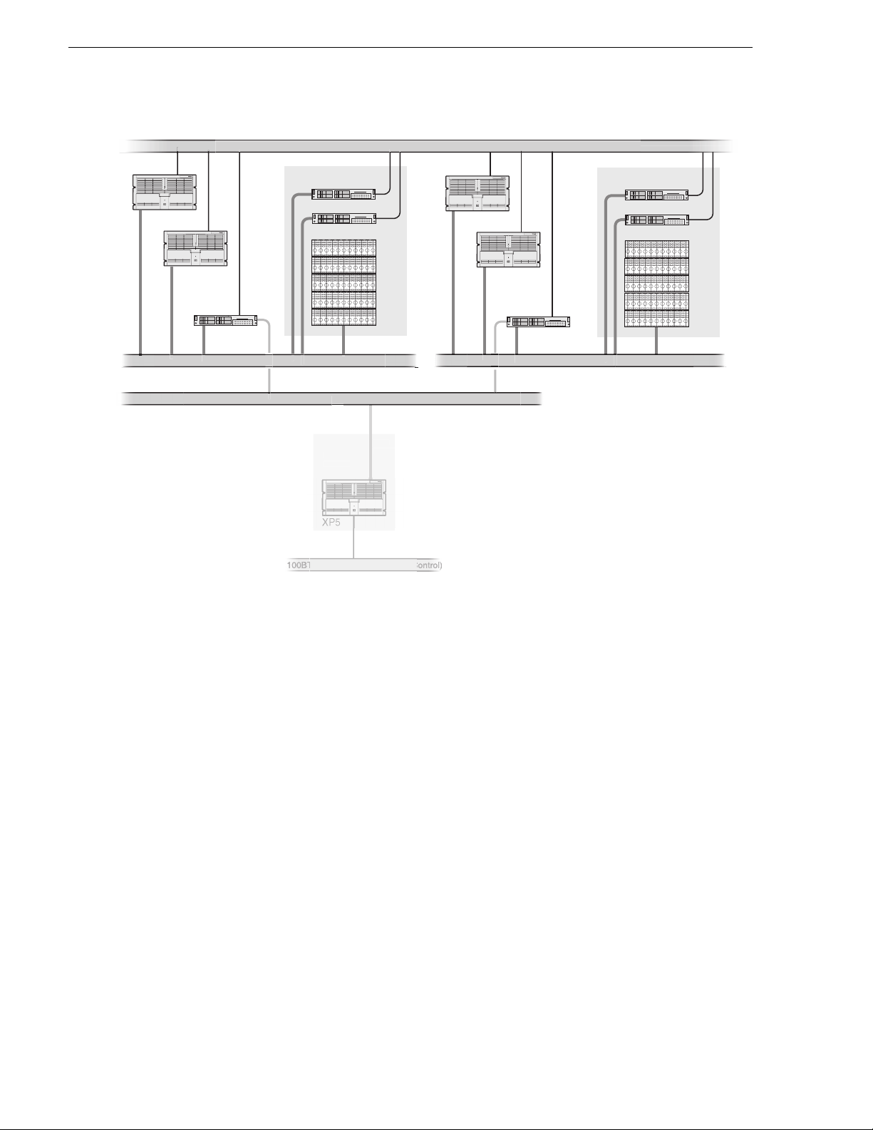
Chapter 5 UIM-SAN-FCIP Installation: Grass Valley Open SAN System
C
e
30
m
SAN1_XP1
SAN1_XP2
SAN1_UIM1
Fibre Channel Switch Fabric (SCSI)
FC IP Network (Streaming) x.x.230.x
Notes:
[1] Optional redundant Ethernet
fabrics, and Fibre Channel switch
fabrics are not shown.
SAN1
10/100BT Ethernet LAN (Control) x.x.100.x
Shared Storage
SAN1_FSM1
SAN1_FSM2
Fibr
el
rofile XP
latfor
(Standalone)
hann
.xx.x.2
SAN2_XP1
SAN2_XP2
SAN2
Shared Storage
SAN2_FSM1
SAN2_FSM2
SAN2_UIM1
Fibre Channel Switch Fabric (SCSI)
Ethernet LAN x.x.100.x (
To modify the FSM master hosts file:
1. On the FSM, make a copy of the master hosts and name it hosts.bak. The hosts fi le
is located at c:\winnt\system32\drivers\etc\hosts.
This copy can be used to recover the original file if there is a problem.
2. Open the hosts file at c:\winnt\system32\drivers\etc\hosts using Notepad or some
other text editor.
3. Use the following steps to type the entry for the UIM-SAN-FCIP network interface
connected to the control LAN.
a. On a single line , e nte r the IP address for the network interface connected to the
control LAN.
b. Insert a few sp aces, then type the U IM-SAN-FC IP host name followed by t he
_UIM1 suffix.
For example:
192.168.100.157 SAN1_UIM1
c. Insert a few more spa ces, then type all Profile platform ho st names assigned to
this UIM-SAN-FCIP. Use the Profile host name followed by the _UIMFC
suffix.
90 UIM Instruction Manual February 5, 2008
Page 91

Example master hosts file entries for two SANs
For example:
192.168.100.157 SAN1_UIM1 SAN1_XP1_UIMFC SAN1_XP2_UIMFC
4. U se the following steps to type the en try for the UIM-SAN-FCIP Fibre Channel
streaming network interface
a. On a single line, enter the IP address for the Fibre Channel network interface
connected to the FC IP network.
b. In sert a few spaces, then t ype the UIM-SAN-FCIP host name followed by the
_fc0 suffix. (NOTE: The suffix uses the zero character, not the letter ‘o’.)
For example:
192.168.230.157 SAN1_UIM1_fc0
c. Insert a few more spaces, then type all Profile platform host names assigned to
this UIM-SAN-FCIP. Use the Profile host name followed by the _fc0 suff ix.
For example:
192.168.230.157 SAN1_UIM1_fc0 SAN1_XP1_fc0 SAN1_XP2_fc0
5. If you modified the Profile XP platform host names as described in “Specify host
names in the Open SAN” on pag e 82, you must revi se t hose en tr ies i n the host file
now.
6. Save the master hosts file and exit Notepad.
7. Copy the new master hosts file to all network devices in the Open SAN system
including FSMs, Profile XP platforms, other UIM-SAN-FCIPs, and standalone
Profile platforms in the facility that proxy to the UIM.
c:\winnt\system32\drivers\etc\hosts
NOTE: Errors in this configuratio n step will render your med ia exchange network
inoperable. Take great care to enter all information correctly, then recheck for
errors.
February 5, 2008 UIM Instruction Man ual 91
Page 92

Chapter 5 UIM-SAN-FCIP Installation: Grass Valley Open SAN System
Configure the UIM network settings
Refer to your system design and the requirements described in “Specify host names
in the Open SAN” on page 82 and “Specify a subnet addre ss for the FC IP s trea ming
network” on page 83, then configure network settings on each UIM-SAN-FCIP.
1. Power-on the UIM-SAN-FCIP and log on as Administrator (default password:
triton).
2. Modify the UIM-SAN-FCIP host name as follows:
a. Right-click the compu ter icon on th e deskto p, then selec t
Properties to open the
System Properties dialog box.
b. Click the
c. Enter the UIM-SAN-FCIP computer name, then click
d. Click
e. Click
f. Click
g. Click
Network Identification tab, then click Properties.
OK.
Yes to accept non-standard name.
OK to acknowledge the reboot mess age.
OK to close the System Properties dialog box.
NO. Do not reboot at this time.
3. Configure the TCP/IP settings on each UIM-SAN-FCIP network adapter as
follows:
a. Right-click the “My Network Places” desktop icon, then select
Properties to
open the Windows operating system “Network Connections” dialog box.
Depending on the Dell platform, ne twor k connections are displayed as follows:
Name Type Status Device Name
Dell 2650
QLogic FC NIC LAN Enabled QLogic QLA2X00 PCI Adapter
Intel 1000BT Port A LAN Enabled Intel(R) Pro/1000 MT Quad Port Server Adapter
Intel 1000BT Port B LAN Enabled Intel(R) Pro/1 000 MT Quad Port Server Adapter #2
Intel 1000BT Port C LAN Enabled Intel(R) Pro/1 000 MT Quad Port Server Adapter #3
Intel 1000BT Port D LAN Enabled Intel(R) Pro/1000 MT Quad Port Server Adapter #4
Control Team - Intel
Ports A/B
Streamin g T e am -
Intel Ports C/D
Dell 2850
QLogic FC NIC LAN Enabled QLogic QLA2X00 PCI Adapter
Intel 1000BT Port A LAN Enabled Intel(R) Pro/1000 MT Network Connecti on
Intel 1000BT Port B LAN Ena bled Intel(R) Pro/1000 MT Network Connection #2
Intel 1000BT Port C LAN Enabled Intel(R) Pro/1000 MT Dual Port Server Adapter
92 UIM Instruction Manual February 5, 2008
LAN Ena bled Intel(R) Advanced Network Serv ices Virtual Adapter
LAN Ena bled Intel(R) Advanced Network Serv ices Virtual Adapter #2
Page 93

Configure the UIM network settings
Name Type Status Device Name
Intel 1000BT Port D LAN Enabled Intel(R) Pro/1000 MT Dual Port Server Adapter #2
Control Team - Intel
Ports A/B
LAN Ena bled Intel(R) Advanced Network Serv ices Virtual Adapter
Streamin g T e am Intel Ports C/D
Dell 1950
QLogic FC NIC LAN Enabled QLogic QLA2X00 PCI Adapter
Broadcom 1000BT
Port A
Broadcom 1000BT
Port B
Control Team -
Broadcom Ports A
and B
Intel 1000BT Port C LAN Enabl e d TEAM: Streaming Team - Intel(R) Pro/1000 MT Dual
Intel 1000BT Port D LAN Enabled TEAM: Streaming Team - Intel(R) Pro/1000 M T Dual
Streamin g T e am Intel Ports C and D
LAN Ena bled Intel(R) Advanced Network Serv ices Virtual Adapter #2
LAN Enabled Broadcom BCM5708C NetXtreme II GigE (NDIS VBD
Client)
LAN Enabled Broadcom BCM5708C NetXtreme II GigE (NDIS VBD
Client) #2
LAN Enabled BASP Virtual Adapter
Port Server Adapter
Port Server Adapter #2
LAN Enabled TEAM: Streaming Team
b. Right-click the Control Team - … Ports A & B, then select Properties to
configure network settings . Team descri ptions are shown in the table that
follows.
NOTE: Always configure the Ethe rnet network settings using the fault tolerance
teams. Do not select and co nfigure the network adapte rs directly. In non-redunda nt
Ethernet configurations, the unused ports will be ignored.
Connection Name Listed Description Configuration Tasks
QLogic FC NIC Fibre Channel Network Adapter Configure the IP Address,
subnet mask, and othe r
a
Control Team - … Ports A & B Control LAN Team Members
Primary: … 1000 BT Port A
Secondary: … 1000BT Port B
a.
Primary designates the primary adapter for the team. Secondary designates the backup adapter. If the
primary connection is lo st, then re stored, it rejoin s the te am as a mem ber an d no t the prima ry co nnecti on.
When redundant con nections are not used, the unused port is igno red.
:
network settings f or each
connection as required by
your network design and
site requirements. (Refer to
“Specify a subnet address
for the FC IP streaming
network” on page83.)
Contact your local network
administrator of details.
February 5, 2008 UIM Instruction Man ual 93
Page 94

Chapter 5 UIM-SAN-FCIP Installation: Grass Valley Open SAN System
NOTE: Wh en prompted to restart, click Yes. Wait until all connections are
configured.
c. Repeat step b for the QLogic FC NIC.
4. After all connections are configured, restart the UIM-SAN-FCIP.
5. Proceed to the next procedure “Connect UIM-SAN-FCIP network cables
Dell 2850”.
94 UIM Instruction Manual February 5, 2008
Page 95

Connect UIM-SAN-FCIP network cables Dell 2850
Connect UIM-SAN-FCIP network cables
Dell 2850
Connect the network cables as shown. Be sure to consult your Ethernet and Fibre
Channel switch fabric designs as you make connections. Refer to “Onsite pla nni ng”
on page 82.
UIM
CAUTION: Do not connect IP port on the
!
UIM-SAN-FCIP to the Fibre Channel SCSI
fabric. The IP driver will cause Open SAN
record and playout to fail. Do not mix IP and
SCSI fabrics on the same Fibre Channel switch.
Fibre Channel IP
Streaming Port
To Fibre Channel
Switch (IP)
Fibre Channel
SCSI Connection
To Fibre Channel
Switch (SCSI)
NOTE:
1. Ensure that the redundant and primary ports are
connected to different switches. If redundant connections
are not used, unused ports are ignored.
2. Verify that the Ethernet switches support Spanning Tree
Protocol (STP), and that the protocol is configured as
described in “Redundant Ethernet network requirements”
on page 17.
Intel Ports A & B
AB
Control T eam
(Control LAN)
February 5, 2008 UIM Instruction Man ual 95
Page 96

Chapter 5 UIM-SAN-FCIP Installation: Grass Valley Open SAN System
Connect UIM-SAN-FCIP network cables Dell 1950
Connect the network cables as shown. Be sure to consult your Ethernet and Fibre
Channel switch fabric designs as you make connections. Refer to “Onsite pla nni ng”
on page 82.
CAUTION: Do not connect IP port on the
!
UIM-SAN-FCIP to the Fibre Channel SCSI
fabric. The IP driver will cause Open SAN
record and playout to fail. Do not mix IP and
SCSI fabrics on the same Fibre Channel switch.
Control T eam
Ports A/B
(Control LAN)
A
B
UIM
Fibre Channel IP
Streaming Port
To Fibre Channel
Switch (IP)
NOTE:
1. Ensure that the redundant and primary ports are
connected to different switches. If redundant connections
are not used, unused ports are ignored.
2. Verify that the Ethernet switches support Spanning Tree
Protocol (STP), and that the protocol is configured as
described in “Redundant Ethernet network requirements”
on page 17.
Fibre Channel
SCSI Connection
To Fibre Channel
Switch (SCSI)
96 UIM Instruction Manual February 5, 2008
Page 97

Install CVFS client software on the UIM-SAN-FCIP
Install CVFS client software on the UIM-SAN-FCIP
Use the following sec tions to install , licens e, and conf igure the CVFS client so ftware
on the UIM-SAN-FCIP.
Install CVFS client software on the UIM
Use the following steps to install the CVFS client software o n the UIM-SAN-FCIP.
This procedure requires the CVFS setup program located on the Open SAN File
System CD-ROM or downloaded from the Thomson Grass Valley FTP site.
NOTE: Be sure to install the correct client software ve rsion. The software version
must match the CVFS software running on t he File Sys tem Manager ( FSM) in the
Open SAN system.
To install the file system client software:
1. First verify the UIM-SAN-FCIP Fibre Channel connection to the shared storage
disks using the following steps.
a. Right-click the computer icon on the desktop, then select
b. S elect Device Manager in the tree.
c. Expand Disk drives.
d. V erify that the LUNs in t he SCSI fabric are displayed.
Manage.
The UIM-SAN-FCIP must “see” the physical drives at the SCSI level in order
to support the Open SAN file system. If not, check Fi bre Channel adapter
cabling to be sure that the FC IP and SCSI connections are not reversed. Also
refer to “If you have a problem: UIM-SAN-GEIP” on page 116.
2. In sert the Open SAN File System CD-ROM into the UIM-SAN-FCIP’s CD-ROM
February 5, 2008 UIM Instruction Man ual 97
Page 98

Chapter 5 UIM-SAN-FCIP Installation: Grass Valley Open SAN System
drive.
The installation program starts automatically and guides you through the
installation process.
3. On the Welcome is displayed, click
4. On the Setup page, click
Next, then accept the license agreement to continue.
Next.
5. On the Choose Destination Location page, click
98 UIM Instruction Manual February 5, 2008
Browse, to type
Page 99

C:\MediaAreaNetwork, then click OK to close.
NOTE: Do not use spaces in the directory name.
Install CVFS client software on the UIM
6. Click
Next, then answer Yes when prompted to create the directory.
7. When the File System Components page appears, select the component s shown,
then click
Next.
8. In the Select Program Folder page, type Media Area Network, th en click
February 5, 2008 UIM Instruction Man ual 99
Next.
Page 100

Chapter 5 UIM-SAN-FCIP Installation: Grass Valley Open SAN System
9. On the Start Copying Files page, click Next.
10.When prompted to view Help Files during installation, click
No.
11.When the Choose Options to Complete the Installation screen appears, leave the
check boxes blank and click
Next.
12.When the File System Name Service Locations screen appears, enter the name or
IP address of the File System Mana ger (FSM).
If your Open SAN uses redun dant FSMs, e nt er the redundant FSM here as shown.
100 UIM Instruction Manual February 5, 2008
 Loading...