

Page 1
Turbo™
INTELLIGENT DIGITAL DISK RECORDER
Quick Start Guide
071-8379-01
JULY 2005
the most watched worldwide
Page 2

Safety Summary Use Prop er Power Co rd – To avoid fire hazard, use only the power cord specified for this
product.
Ground the Product – This product is ground ed throug h the g roundin g conduc tor of t he powe r
cord. To avoid electric shock, the grounding conductor must be connected to earth ground.
Before making connections to the input or output terminals of the product, ensure that the
product is properly grounded.
Do Not Operate Without Covers – To avoid el ectric shock or fire hazard, do not operat e this
product with covers or panels removed.
Do Not Operate in Wet/Damp Conditions – To avoid electric shock, do not operate this
product in wet or damp conditions.
Do Not Operate in an E xplos ive A tmosp here – T o avoid injur y or fi re haz ard , do n ot oper ate
this product in an explosive atmosphere.
Avoid Exposed Circuitry – To avoid injury, remove j ew elry s uch a s ri ngs, watch es, a nd othe r
metallic objec ts. Do not touch exposed connection s and components when power is present.
Symbols on the
The following symbols may appear on the product:
Product
DANGER high voltage
Protective ground (earth) terminal
!
ATTENTION – refer to manual
Copyright Copyright © 2005 T homson Broa dcas t and Medi a Solu tio ns, Inc. All righ ts res er ved. Prin ted in
the United States of America. This document may not be copied in whole or in part, or
otherwise reproduced except as specifically permitted under U.S. copyright law, without the
prior written consent of Thomson Broadcast and Media Solutions, Inc., P.O. Box 59900,
Nevada City, Cal i fornia 95959-7900
Trademarks Grass Valley, Turbo, M-Series, Profile, and Profile XP are either registered trademarks or
trademarks of Thomson Broadcast and Media Soluti ons, Inc. in the United States and/or other
countries. Other trademarks used in this document are either registered trademarks or
trademarks of the manufacturers or vendors of the associated products. Thomson Broadcast
and Media Solutions, Inc. products are covered by U.S. and foreign patents, issued and
pending. Additional information regarding Thomson Broadcast and Media Solutions, Inc.
trademarks and other proprietary rights may be found at www.thomsongrassvalley.com.
Disclaimer Product options and specifications subject to change without notice. The information in this
manual is furn i shed for informati onal use only, i s subject to change without notice, and should
not be construed as a commitment by Thomson Broa dcast and Media Solu tions, I nc. Thomso n
Broadcast and Media Solutions, Inc. assumes no responsibility or liability for any errors or
inaccuracie s that may appear in this publ i cation.
U.S. Government
Restricted Rights
Legend
This Product
Incorporates Licens ed
Software
Use, duplicat ion, o r disclos ure by t he Unite d States Governme nt is su bject to restric tions as s et
forth in subparagraph (c)(1)(ii) of the Rights in Technical Data and Computer Software clause
at DFARS 252.277-7013 or in subparagraph c(1) and (2) of the Commercial Computer
Software Re st ri cted Rights clause at F AR 52.227-19, a s applicable. Manufacturer is Thomson
Broadcast and Media Solutions, Inc., P.O. Box 59900, Nevada City, California 95959-7900
U.S.A.
Use of the software installed on the this product or on the associated media is subject to the
terms of end user licen se agree ments. You sh ould not use the softwa re until y ou have read th e
end user license agreements. By using the software, you signify that you have read the end
user license ag reements acces sible through the Help | About dialog box and accept their terms .
Revision Status
Rev Date Description
03 May 2005 Final Draft of the Turbo Quick Start Guide — 071-8379-00
06 July 2005 Removed software version number — 071-8379-01
2 Turbo Quick Start Guide 06 July 2005
Page 3
Installation
1
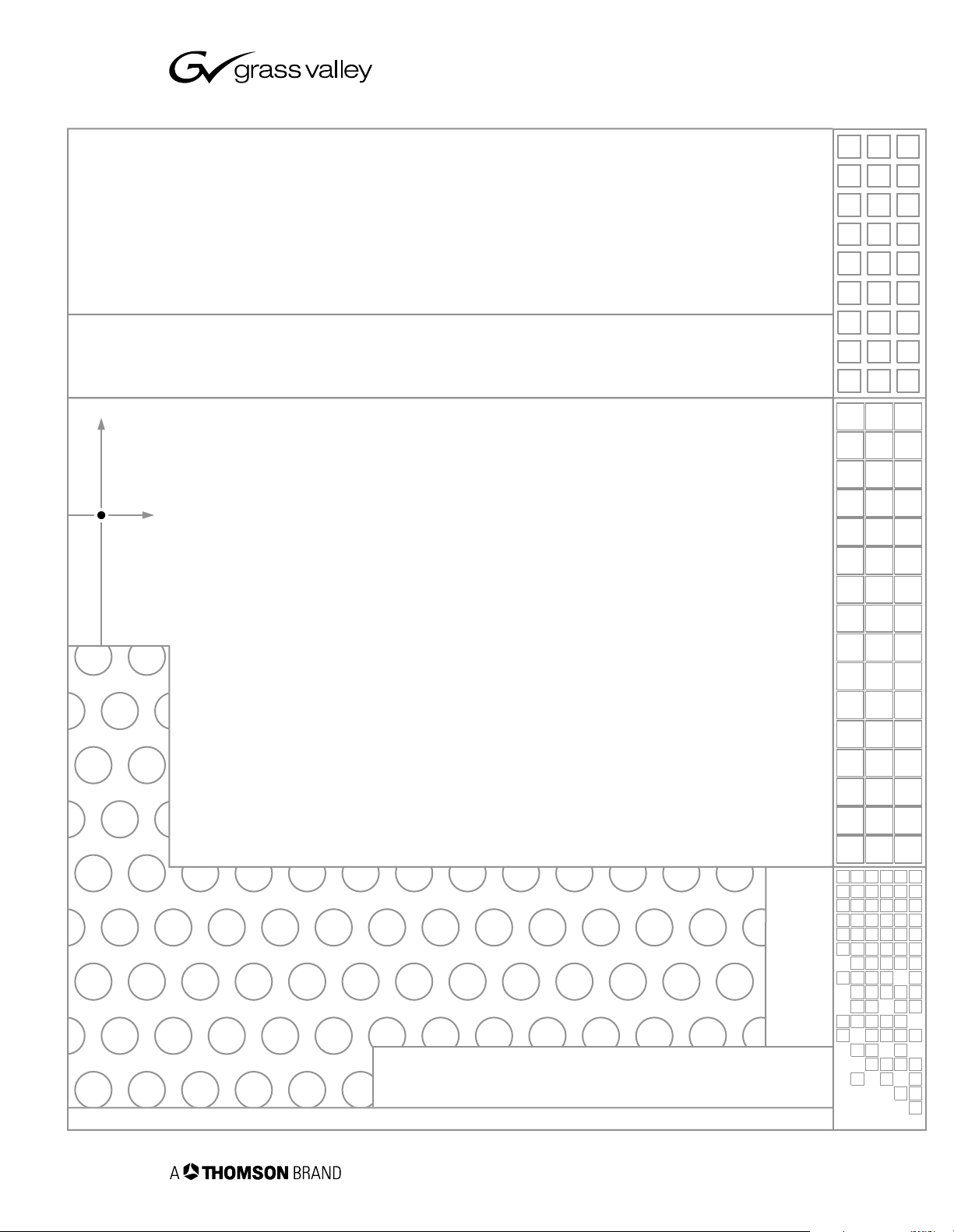
Unpack and check contents
Before you begin, unpack and identify the following items:
KeyboardPower Cord
Mouse
Turbo iDDR
Quick Start Guide
System Software CD-ROM
Documentation CD-ROM
2
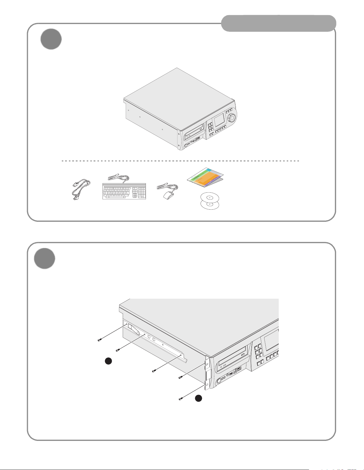
If desired, mount in an equipment rack
Power-off the Turbo iDDR, and remove the power cord. Rack-mount the Turbo using the optional rack-mount kit.
Refer to the Turbo Rack-Mount Kit Instructions on the Documentation CD-ROM.
1
Install rails
using screws
provided
2
Remove standard screws
and use longer screws
provided in rack-mount kit
to install brackets
06 July 2005
3
Page 4
Installation
3
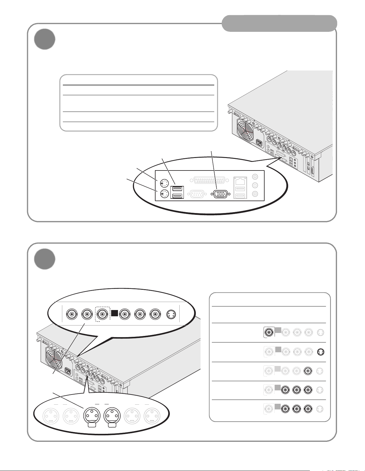
Connect mouse, keyboard, & monitor
(if desired)
You can operate the Turbo iDDR in Front Panel Control mode or Workstation Control mode. Make connections as
described in the following table.
To use this control mode: Make these connections:
Front Panel Control None
Front Panel Control with external
Keyboard
keyboard for text entry
Workstation Control Keyboard, mouse, & monitor
a.
You can use the front panel USB port, if desired.
USB Connector
Connect mouse and
keyboard supplied
PS/2 Mouse
PS/2 Keyboard
a
h
s
VGA Monitor
u
P
h
s
u
P
4
Connect Recorder inputs
Digital audio
-or-
Analog audio
Ch 1 P1
LTC In S/PDIF
Ch 2
SDI
h
s
u
P
h
s
u
P
Ch 1 Ch 2
R1
Push
R1
INPUT
SD RECORDER
Push
RPB CMPST/Y S- Video
P
Ch 1 Ch 2
P2
Supported Video Types
a
Video Resolutions 720 x 480 I @ 29.97Hz
720 x 576 I @ 25Hz
SDI .
S-Video .
Composite Analog .
Component
Analog (VTR)
Component
Analog (DVD)
a.
To select a signal source, see “Modify settings as required”
on page 8.
R1
INPUT
SDI Pb CMPST/Y
SD RECORDER
R1
INPUT
SDI Pb CMPST/Y
SD RECORDER
R1
INPUT
SDI Pb CMPST/Y
SD RECORDER
R1
INPUT
SDI Pb CMPST/Y
SD RECORDER
R1
INPUT
SDI Pb CMPST/Y
SD RECORDER
Pr
Pr
Pr
Pr
Pr
S-Video
S-Video
S-Video
S-Video
S-Video
.
06 July 2005
4
Page 5
Installation
5
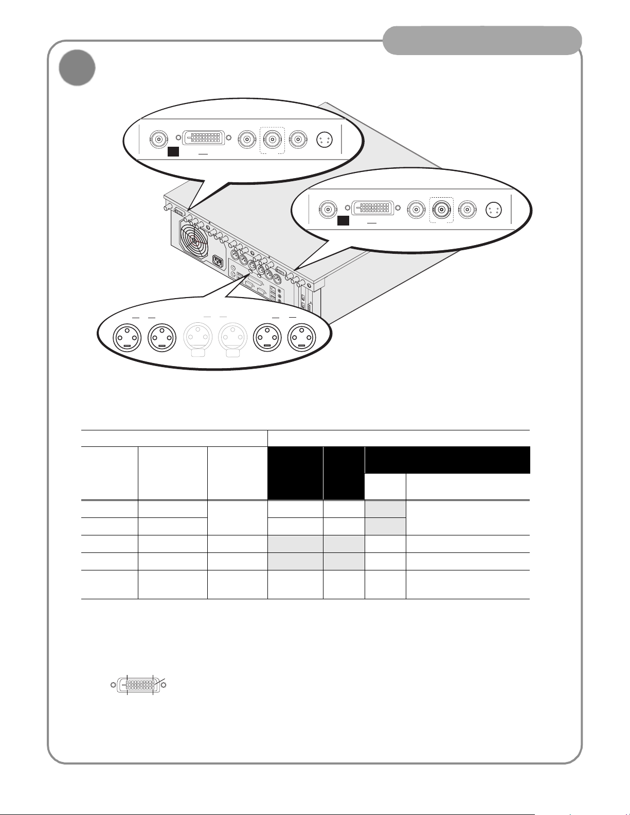
Connect Player 1 and 2 outputs
Ch 1 P1
DVI-I
P1 OUTPUT HD/SD PLAYER
Ch 2
Ch 1 Ch 2
Push
R1
Push
h
s
SDILTC Out S/PDIF Composite
u
P
h
s
u
P
Ch 1 Ch 2
S- Video
DVI-I
P2 OUTPUT HD/SD PLAYER
P2
SDILTC Out S/PDIF Composite S- Video
Video output formats and connectors
Play Channel Setting Video Output Types Available
Video Type
Setting
NTSC 720 x 480 I 4:3 or 16:9 !! DVD Player: Y, Pb, Pr
PAL 720 x 576 I !!
XGA 1024 x 768 P 4:3 or 16:9
WXGA 1365 x 768 P 16:9 ! Computer Monitor (RGBHV)
1080i 1920 x 1080i 16:9 monitor
a.
Aspect ratio conversion mode is user selectable— bars, crop, or bars & crop.
b.
Sync on Y or G when 3-wire formats are used.
c.
The monitor output is down-converted and not timed to the reference input. It is provided for monitoring purposes only.
DVI-I Connector
8
DVI-I
Resulting
Resolution
1724
9
1
Aspect
Ratio
Available
a
S-Video
Composite
SDI DVI -I
Digital Analog Componentb
(Selectable)
a
c
monitor ! SMPTE 274M (RGB)
! Computer Monitor (RGBHV)
SMPTE 274M (YUV)
The DVI-I connector provides both digital and component analog output signals at the same
time. You must supply a standard DVI-I cable or adapter to make DVI digital and/or component
analog video connections. (Optional cable available, contact your Thomson Grass Valley
representative.)
06 July 2005
5
Page 6
Installation
P
m
R
C
ease Wa
6
Connect power and turn power on
1
Connect Turbo iDDR and all
external equipment to a
grounded AC power source,
and turn on power.
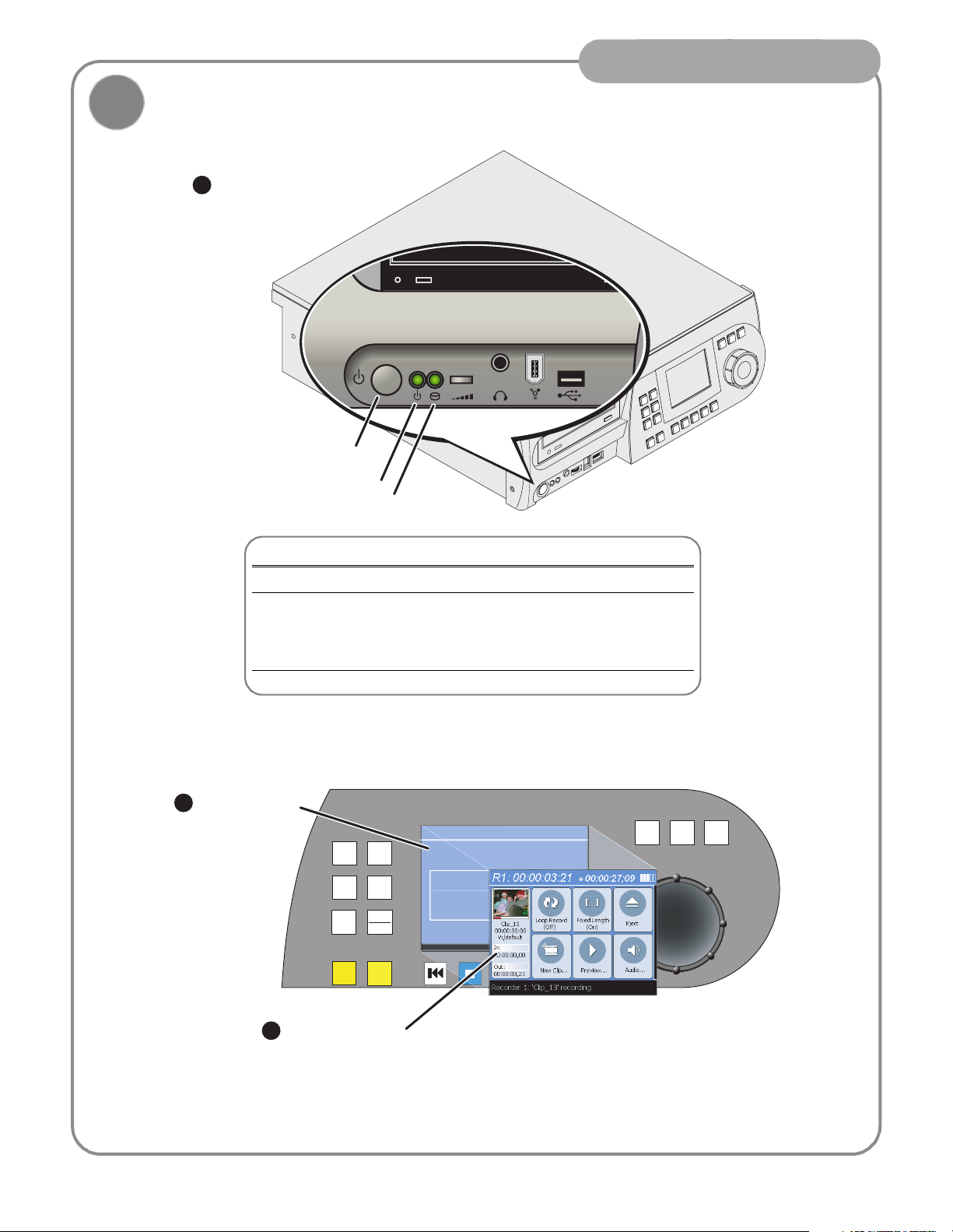
Standby button
Power on indicator
Drive busy indicator
Front Panel Features
Standby button Turns Turbo iDDR on and off.
Power indicator ON: Power is on and the Turbo is operational.
Blinking: Turbo needs service. Refer to Turbo Service
and Troubleshooting Guide.
OFF: Power is in standby mode.
Drive busy indicator Indicates data is being written or read.
2
Monitor system
startup messages
JOG
SHTL
VAR
R1
P1
P2
MARK
OUT
3
Front Panel Control
MENU
CLIPS
ESC
SHIFT
MARK
OUT
anel Control Syste
eceiving
Pl
mode display after
startup
06 July 2005
6
Page 7
Installation
7
Configuration and Operation
Front Panel Operation: Refer to page 8 to configure
and operate the Turbo iDDR using the front panel
control mode.
(Keyboard if desired)
AppCenter Workstation Operation: Refer to page 15
to configure and operate the Turbo iDDR using AppCenter Workstation mode.
06 July 2005
7
Page 8
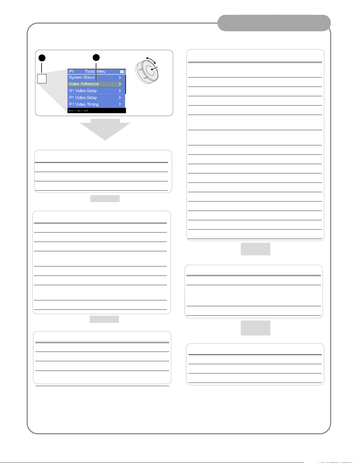
Modify settings as required
o
Front Panel Operation
To access Turbo iDDR configuration:
Press
1
button twice
MENU
Menu
2
Scroll and select
a menu item
All Channels Settings
Setting Choices
Reference Standard NTSC (59.94) or PAL (50Hz)
Time of Day Source System Clock or LTC Input
Audio Reference Level 0dB, 4dB, 8dB
R1 (Recorder Channel) Settings
Setting Choices
Compression Format MPEG
Recording Data Rate 4,8,12,15 Mb/s
Video Noise Reduction None, Low, Medium, High
Video Input Type SDI, S-Video, Analog Composite,
Analog Component
Audio Input Type Analog or Digital (S/PDIF)
Audio Input Trim (Analog) +/-12dB
Audio Input Format (S/PDIF) 16-bit PCM
AC-3
Timing Offset +/-200ms
Scroll
Push t
Select
P1 and P2 (Player Channels) Settings
Setting Choices
Video Output Format NTSC (SD), XGA (1024x768), WXGA
(1365x768), 1080i (1920x1080)
Aspect Ratio Standard or Widescreen
Aspect Ratio Conversion Bars, Crop, Bars and Crop
Output Component Type RGB, Y,Pb,Pr
Output Pedestal On or Off
Still-play Mode Field (reduce jitter on freeze frame)
Frame (enhances still graphics display)
Test Mode (colorbars) On or Off (generates colorbars/1kHz
4dbu audio tone)
Video Gain 0-255
Chroma Gain 0-255
Chroma Phase -127 to +128
Black Level 0-15
Sharpness 0-12
Frame Offset 0-1 frames
Line Offset (coarse) 0-524 lines
Sample Offset (fine) 0-1715 samples
Analog Sub-pixel Offset 0-255
Timing Offset +/-200ms
GPI Input Setup
Setting Choices
Trigger Channels None, R1, P1, P2
Trigger Action Play, Record, Stop, Rewind, Fast Forward,
Cue Start, Cue End, Eject, Preview, Cue Next
Event, Cue Previous Event, VAR Playback
Active High or Low
Panel Set up
Setting Choices
Jog Speed -1x to 1x, -1x to 3x
Shuttle Speed -16x to 16x, -32x to 32x
VAR Setting 0.25x, 0.5x, 0.75x
Always start at
VAR preset
Yes or No
GPI Output Setup
Setting Choices
Channel None, R1, P1, or P2
Trigger Name <User specified name>
Active High or Low
06 July 2005
8
Page 9

Recording a clip
Front Panel Operation
Press
1
MENU
R1
P1
CLIPS
ESC
P2
SHIFT
MARK
MARK
OUT
OUT
To rename the clip,
5
press
Menu
select
Rename
R1
, then
2
Verify signal sources
(Refer to configuration
menus on the previous
page)
4
Scroll
.
Press
+
[
or
to start record, then
press to stop.
Push to
Select
6
Use the control knob to
enter text, or use an
external keyboard.
3
Press to adjust audio
level, then press
to return.
JOG
SHTL
]
VAR
ESC
SHIFT
Other Turbo iDDR Record Modes
Touch to name the clip first, then
start recording.
Touch to specify a loop length,
then start recording.
Records a continuous loop.
Overwrites oldest unused media.
Touch to specify clip length, then
start recording.
Record stops when clip length is
reached.
R1
P1
P2
MARK
IN
MENU
CLIPS
ESC
SHIFT
MARK
OUT
7
Press
to the Recorder
display.
ESC
SHIFT
to return
8
Load and play the
clip in a play channel.
JOG
9
SHTL
VAR
06 July 2005
Page 10

Importing media: 1394 DV Device
The IEEE 1394 interface allows for importing and recording media from a digital recording device that uses DV or
MPEG2 format. After connecting the DV device and selecting the IEEE 1394 input for the Record channel, you can
use the Turbo transport controls to control the DV device remotely through the 1394 connection.
Front Panel Operation
Connect the DV
1
device to the front
or a rear panel
1394 connector.
2
R1
P1
P2
MARK
MARK
OUT
IN
R1
P1
P2
Press
R1
MENU
MENU
CLIPS
CLIPS
ESC
ESC
SHIFT
SHIFT
MARK
MARK
OUT
OUT
Cue the DV device
4
using the transport
controls or control
knob
h
s
u
P
h
s
u
P
NOTE: The front panel 1394 port
and the top rear-panel port are
electrically the same. Use one or
the other of these connectors.
Select 1394
3
input
JOG
SHTL
SHTL
VAR
VAR
6
Press to
stop record.
Load and play the
JOG
5
Press to preroll
the DV device
and start import
clip in a play channel.
10
06 July 2005
Page 11

Importing media
You can import media created on other digital video devices or PCs. The media may be imported from a CD-ROM,
DVD, USB flash drive, and external USB or 1394 disk drives.
1
Do one of the following:
!
Insert a CD-ROM or DVD
!
Connect 1394
external disk drive
!
Insert a USB flash drive,
or connect an external
USB disk drive
NOTE:
The front panel 1394 port
and the top rear-panel port are
electrically the same. Use one or
the other of these connectors.
Front Panel Operation
Scroll
Push to
Scroll
Select
JOG
My Documents
Push to
Select
SHTL
VAR
6
After import, load
and play the clip in
a play channel.
2
Press
Clips
R1
P1
P2
MARK
OUT
3
MENU
CLIPS
ESC
SHIFT
MARK
OUT
Press
Menu
Scroll and
4
select
5
Browse to
locate and
select the file
Import
My Computer
Recycle Bin
.
DesktopR1:
My Network Places
to import.
Supported File Formats
Video File Formats: DV encoded AVI (.avi)
General Exchange Format (.gxf)
For the supported file formats, all resolutions and
frame rates are supported.
Quicktime (.qt, .mov)
Windows Media (.wmv)
MPEG PS (.mpg, .m2v, .m2p, .m2, .mpeg, .vob)
Graphic File Formats: .jpg, .bmp, .tiff, .tga, .gif, .png Still image files or image sequence files
11
06 July 2005
Page 12

Playing a clip
MARK
OUT
Press P1,
1
then
R1
P1
P2
MENU
CLIPS
ESC
SHIFT
MARK
OUT
Clips
2
Scroll and
select a clip
Front Panel Operation
Scroll
Push to
Select
JOG
SHTL
VAR
MENU
R1
P1
CLIPS
ESC
P2
SHIFT
MARK
MARK
IN
OUT
Other Turbo Player Modes
To output black when the play channel is stopped, make sure E-to-E is Off.
To output the record channel input signal when the play channel is stopped,
touch E-to-E to turn On.
Verify clip
3
thumbnail
and name
Press to play
5 6
the clip
Make sure
4
Off
to display first
frame of the clip
E to E
is
SHTL
JOG
Adjust audio level,
then press
to return.
ESC
SHIFT
VAR
To play the clip repeatedly, touch Loop to turn On; touch again to turn Off.
12
06 July 2005
Page 13

Trimming a clip
Press P1,
1
then
Clips
MENU
R1
P1
CLIPS
ESC
P2
SHIFT
MARK
MARK
OUT
IN
2
Scroll and
select a clip
JOG
Front Panel Operation
Scroll
Push to
Select
SHTL
VAR
R1
P1
P2
MARK
IN
MENU
CLIPS
ESC
SHIFT
MARK
OUT
6
Verify clip name
3
and thumbnail
Set mark in or
out to the current
frame and trim
the clip
Make sure
4
Off
to display first
frame of the clip
<<< or >>> symbols are
7
displayed to indicate the
mark can be cleared to
reveal more source
material
E to E
is
JOG
SHTL
Shuttle/Jog
5
to a new
frame
VAR
13
06 July 2005
Page 14

Creating a simple playist
o
Front Panel Operation
Press P1 or
1
R1
P1
P2
MARK
IN
R1
MENU
CLIPS
ESC
SHIFT
MARK
OUT
3
MENU
Press
Clips
P2
2
Press
Edit List
JOG
4
Scroll and select
to add clips
JOG
SHTL
SHTL
VAR
VAR
Scroll
Push t
Select
P1
P2
MARK
IN
R1
P1
P2
MARK
IN
CLIPS
ESC
SHIFT
MARK
OUT
MENU
CLIPS
ESC
SHIFT
MARK
OUT
SHTL
JOG
VAR
Press to return
5
to Edit List display
14
Press to play
6
the list
06 July 2005
Page 15

Using AppCenter Workstation
Open the
1
AppCenter
shortcut
Workstation Operation
Select
2
View | Workstation
Modify settings as required
To access Turbo iDDR configuration:
Select System, then
1
Configuration
Click a tab and
2
select menu items
15
06 July 2005
Page 16

Workstation Operation
System Settings
Setting Choices
Reference Standard NTSC (59.94) or PAL (50Hz)
Time of Day Source System Clock or LTC Input
Audio Reference Level 0dB, 4dB, 8dB
R1 (Recorder Channel) Settings
Setting Choices
Compression Format MPEG
Recording Data Rate 4,8,12,15 Mb/s
Video Noise Reduction None, Low, Medium, High
Video Input Type SDI, S-Video, Analog Composite,
Audio Input Type Analog or Digital (S/PDIF)
Audio Input Trim (Analog) +/-12dB
Audio Input Format (S/PDIF) 16-bit PCM
Timing Offset +/-200ms
Display Audio Meters Yes or No
Analog Component
AC-3
Panel Set up
Setting Choices
Jog Speed -1x to 1x, -1x to 3x
Shuttle Speed -16x to 16x, -32x to 32x
VAR Setting 0.25x, 0.5x, 0.75x
Always start at
VAR preset
Yes or No
P1 and P2 (Player Channels) Settings
Setting Choices
Video Output Format NTSC (SD), XGA (1024x768), WXGA
(1365x768), 1080i (1920x1080)
Aspect Ratio Standard or Widescreen
Aspect Ratio Conversion Bars, Crop, Bars and Crop
Output Component Type RGB, Y,Pb,Pr
Output Pedestal On or Off
Still-play Mode Field (reduce jitter on freeze frame)
Frame (enhances still graphics display)
Test Mode (colo rbars) On or Off (generates colorbars/1kHz 4dbu
audio tone)
Video Gain 0-255
Chroma Gain 0-255
Chroma Phase -127 to +128
Black Level 0-15
Sharpness 0-12
Frame Offset 0-1 frames
Line Offset (coarse) 0-524 lines
Sample Offset (fine) 0-1715 samples
Analog Sub-pixel Offset 0-255
Timing Offset +/-200ms
Display Audio Meters Yes or No
GPI Input Setup
Setting Choices
Trigger Channels None, R1, P1, P2
Trigger Action Play, Record, Stop, Rewind, Fast Forward,
Cue Start, Cue End, Eject, Preview, Cue Next
Event, Cue Previous Event, VAR Playback
Active High or Low
GPI Output Setup
Setting Choices
Channel None, R1, P1, or P2
Trigger Name <User specified name>
Active High or Low
06 July 2005
16
Page 17

Record a clip
Verify
2
Recorder
mode
Select
1
the
record
channel
Rename clip
6
5
Stop record
Workstation Operation
4
Begin record
Adjust audio
3
Related operations
To change the timecode source, click Recorder | Options, select your
timecode source, and click OK.
If video source is widescreen format (16:9), click Recorder | Widescreen.
To enable Loop record mode, click the Time Dome, then choose
Continuous Record in the pop-up menu.
17
Recorder
Options
Recorder
✓ Widescreen
06 July 2005
Page 18

Play a clip
Verify
2
Player
mode
Select a play
1
channel
4
Play the clip
Workstation Operation
Drag a clip into the
3
play channel
Related operations
To output black when the play channel is stopped, open the
Player menu and uncheck E-to-E.
To output the record channel input signals when the play
channel is stopped, open the Player menu and check E-to-E.
Player
E to E
Player
✓ E to E
To play the clip repeatedly, click the Time Dome, then choose
Loop Mode in the pop-up menu.
The clip aspect ratio is converted to match the play channel aspect ratio using the conversion setting you choose.
To change the conversion method, refer to “Modify settings as required” on page 15.
Setting Description Standard to Widescreen Widescreen to Standard
Crop Crop picture to fit
Bars Pad picture with
bars
Bars &
Crop
Crop and pad
picture with bars
06 July 2005
18
Page 19

Trim a clip
Verify
2
Player
mode
Select a play
1
channel
Set in or out
5
mark to the
current frame
Workstation Operation
Drag a clip into the
3
play channel
4
Locate a frame
19
06 July 2005
Page 20
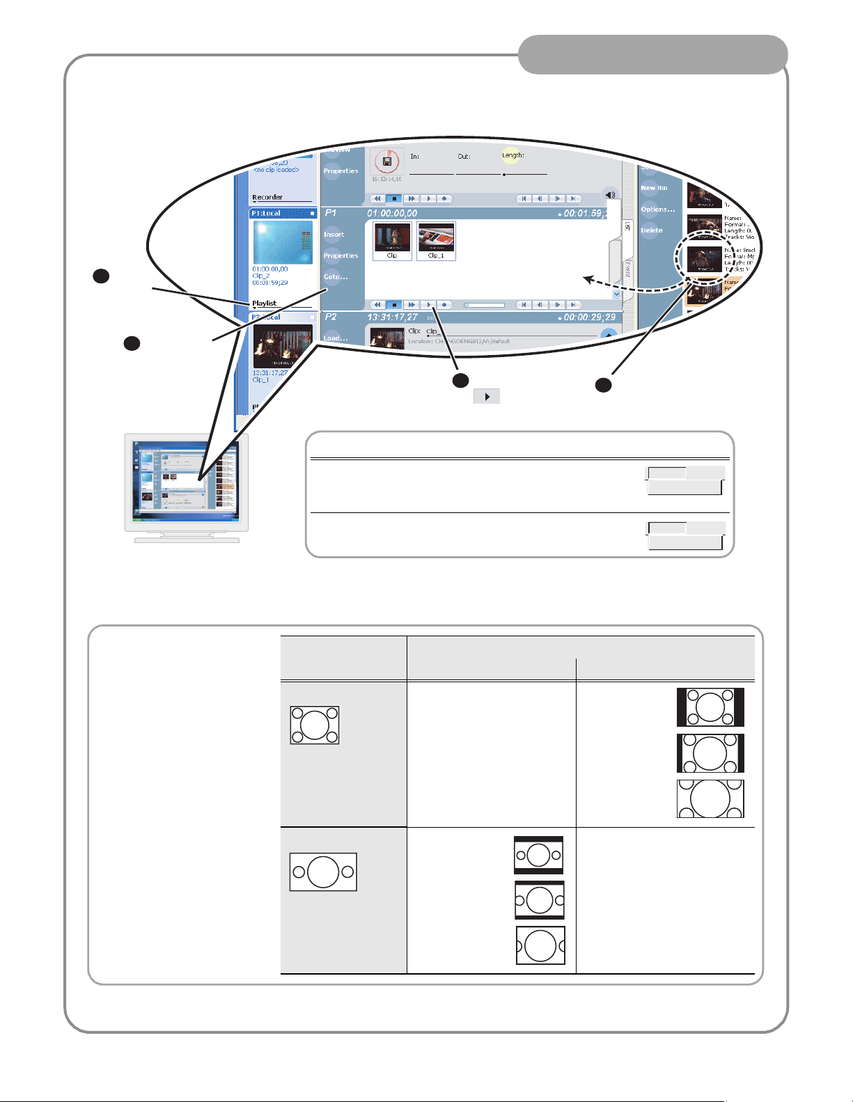
Create a playlist
Select
2
Playlist
mode
Select a play
1
channel
Workstation Operation
EventList
4
Play the list
Related operations
To lock or unlock a playlist, highlight the list, in the Playlist
menu select Properties, then select the General tab and check
or uncheck Locked.
Drag clips into position
3
in the playlist
Playlist
Properties
The Turbo iDDR can play clips
with different aspect ratios in a
single playlist. How the media is
displayed is determined by the
play channel widescreen setting
and clip aspect ratio. The play
channel determines the event
aspect ratio by examining the
source clip aspect ratio attribute
set when the clip was recorded.
The following table describes how
the Turbo iDDR displays mixed
aspect ratios. Refer to “Modify
settings as required” on page 15
to select aspect ratio conversion
method.
To add a section to a playlist click Playlist | Add Section.
.
Source Clip
Aspect Ratio
Standard (4:3) No conversion Bars
Widescreen (16:9) Bars
Play Channel Widescreen Setting and conversion Method
Standard (4:3) Widescreen (16:9)
(Letterbox)
Bars & Crop
(Half-letterbox)
Playlist
Add Section
(Pillarbox)
Bars & Crop
(Half-Pillarbox)
Crop (zoom)
No conversion
20
Crop
06 July 2005
Page 21

Front Panel Controls
The following table describes clip playout using front panel transport controls.
Operator Tips
Front Panel
Control
+
ESC
+
SHIFT
+
ESC
+
SHIFT
Task Customized Operation
Record – Press REC. You can change to PLAY +
REC (hold down Play, then
press Record)
Stop – Press STOP to stop Record/Play.
Play – Press PLAY to start playback.
Rewind – Hold down REW, then release the button to cause
Selectable rewind speed.
the clip to return to the previous mode.
Fast Forward – Hold down FF, then release the button to
cause the clip to return to the previous mode.
Cue to beginning and stop playout – Hold down STOP, then
press REW.
Cue to beginning and continue playout – Hold down SHIFT,
then press REW.
Cue to end and stop playout – Hold down STOP, then press
FF.
Cue to end and continue playout – Hold down SHIFT, then
press FF.
Frame advance – Tap and release the FF button (in stop
mode).
Frame reverse – Tap and release the REW button (in stop
mode).
Jog/Shuttle/
Selection
a
Knob
Headphone
Jog – Press JOG, then turn knob. Playback corresponds to
the direction and rotational speed of the knob.
Shuttle – Press SHTL, then rotate the knob for -32x to +32x
normal playback speed.
Variable Speed Play – (slo-mo) Press VAR. Off-speed play
begins. You can rotate the knob to set the play speed
(RANGE: ±1x normal playback speed), otherwise, speed
remains at the preset play speed or the last variable play
speed used. Variable play speed is implemented using
interpolated line and field smoothing.
Selection - Rotate the control knob to scroll through menus
and options displayed in the front panel control mode. Push
in on the knob to make selections.
Used to monitor the audio of the selected channel.
Range of jog speeds can be
set for ±1x or ±3x.
Range of shuttle speeds
±16x or ±32x.
Preset can be set to .25x, .5x
or .75x. Initial play speed can
be set to start at either the
preset speed, or the last play
speed set by the Jog/Shuttle
knob.
The control knob is
back-light LEDs are on when
in selection mode.
Jack & Level
Control
a.
Scrub audio is provided at Shuttle/Jog speeds between +3x to -3x. Outside this range, audio defaults to burst audio at a fixed
window size similar to audio CD behavior.
06 July 2005
21
Page 22

Front Panel Controls: List playout
While playing a list, you can perform the following operations using the Turbo iDDR front panel transport controls
and touch screen.
To: Do this:
Continue playout after a pause in the list Select the Play button.
Play the next event Press the Play and FF buttons (stops playout).
-orPress the Shift and FF buttons (playout continues)
Play the previous event Press the Play and REW buttons (stops playout).
-orPress the Shift and REW buttons (playout continues).
Play the next section Press the Play button and hold down the FF button.
Play the previous section Press the Play button and hold down the REW button.
Skip playback to any event or section in the list First, press and hold the Play button, then select the event or
section using the touch screen.
Operator Tips
22
06 July 2005
Page 23

Keyboard shortcuts
A keyboard can be connected and used in Front Panel control mode or AppCenter Workstation mode to control the
Turbo iDDR. The following describes the keyboard shortcuts available. Keyboard shortcuts are disabled when text
entry dialog boxes are open.
Operator Tips
Esc
~
Tab
Caps
Lock
Ctrl
Channel select
F1 F2 F3 F4 F5 F6 F7 F8 F9 F10 F11 F12
Channel Select
@
!
R1
1
Shift
#
P1 P2
2
3
Q
WE
S
A
Z
X
Alt Alt Ctrl
%
$
4
5
RT
DF
C
V
G
^
6
Y U
B
&
7
H
N
Play/Stop
(
*
9
8
I
J
K
<
M
VAR/-
,
_
)
-
0
{
P
O
L
>
VAR/+
.
[
:
;
?
/
Channel Select
~
@
!
R1
1
P1 P2
2
#
$
3
4
Print
Scrn
SysRq
+
=
\
}
]
"
Enter
'
Shift
Insert
Scroll
Lock
Home
EndDelete
Pause
Break
Page
up
Page
Down
%
5
Basic transport controls
S
A
H
Play/Stop
J
I O
M
K
<
VAR/-
,
L
>
VAR/+
.
:
;
06 July 2005
23
Page 24

If you have a problem
If you have trouble recording or playing, verify basic configuration using the following checklist.
Verify these set tings Control Mode
Video Reference Standard (50Hz/59.9Hz) page 8 page 15
"
" Video Record channel input selection page 8 page 15
" Record channel widescreen mode enabled if video input is 16:9 page 8 page 15
" Audio input selection (Analog or S/PDIF) page 8 page 15
" Timecode source selection (LTC/Internal) page 8 page 15
" Verify play channel DVI output video type selection. Selection must match
the display device. Recorded media is converted if needed to match the
selected play channel video output type. (See page 18.)
Operator Tips
Front Panel Workstation
page 8 page 15
" Verify play channel video output aspect ratio and conversion mode (bars,
crop, bars & crop)
Solving specific problems
The following table provides corrective action for some common record/play problems. Search the table for the
problem you are experiencing, then try the corrective action.
Problem Possible Cause Corrective Action
Play channel video output is
periodically unstable in E-to-E
mode.
The channel output is black in
E-to-E, but playback is fine.
Audio level too high or too low Record or play channel audio level
Audio level indicators are not
displayed in clip thumbnail in
Record channel monitor.
Video reference is not connected. If E-to-E mode is used, you must connect a video
Loss of input signal. Verify that you have a valid input signal.
adjusted too low.
Wrong audio input selected, or
invalid audio input signal.
page 8 page 15
reference signal.
1. Use the audio level in recorder to adjust audio
level. See “Recording a clip” on page 9 or page
17.
2. Use audio level adjust in player to adjust audio
output level. See “Playing a clip” on page 12 or
page 18.
Verify valid audio input, and audio input selection.
See “Recording a clip” on page 9 or page 17.
Distorted audio or no audio Wrong incoming digital audio
coding format selected.
Compression artifacts are
present in the output.
Picture image is too soft or
colors are pastel in appearance.
Digital video display device
does not display properly.
Video data rate setting is too low
for your program material.
Too much noise reduction used on
video input.
Wrong video output type selected
for the Play channel.
24
Verify the input audio format is set correctly (AC-3
Dolby). See “Recording a clip” on page 9 or page
17. If the SPDIF input is used, verify that the input
material is not copy protected.
Select higher video data rate. See “Recording a
clip” on page 9 or page 17.
Reduce noise reduction used. See “Recording a
clip” on page 9 or page 17.
Verify and select video output type required by the
display device (see display device manuals). If
component analog is used, verify the correct
component analog video format is selected.
06 July 2005
Page 25

Finding more information
Other documentation
• Turbo iDDR Documentation CD-ROM
• Online Help in AppCenter Workstation
Web Technical Support
• World Wide Web: http://www.thomsongrassvalley.com/support/
• Technical Support E-mail Address: gvgtechsupport@thomson.net
Operator Tips
Contacting Grass Valley Support
Before placing a call
• Review the setup instructions in this Quick Start Guide.
• Follow instructions in the Service and Troubleshooting Guide located on the Documentation CD-ROM.
Phone Support
Use the following information to contact product support by phone during business hours. Afterhours phone
support is available for warranty and contract customers.
United States (800) 547-8949 (Toll Free) France +33 (1) 34 20 77 77
Latin America (800) 547-8949 (Toll Free) Germany +49 6155 870 606
Eastern Europe +49 6155 870 606 Greece +33 (1) 34 20 77 77
Southern Europe +33 (1) 34 20 77 77 Hong Kong +852 2531 3058
Middle East +33 (1) 34 20 77 77 Italy +39 06 8720351
Australia +61 1300 721 495 Netherlands +31 35 6238421
Belgium +32 2 3349031 Poland +49 6155 870 606
Brazil +55 11 5509 3440 Russia +49 6155 870 606
Canada (800) 547-8949 (Toll Free) Singapore +656379 1390
China +86 106615 9450 Spain + 34 91 512 03 50
Denmark +45 45968800 Sweden +46 87680705
Dubai + 971 4 299 64 40 Switzerland +41 (1) 487 80 02
Finland +35 9 68284600 UK +44 870 903 2022
25
06 July 2005
 Loading...