

Page 1
TRITON routing switcher
Universal X-Y Control Panel
Product model no. TTN-CP-UNI
INSTALLATION MANUAL
MANUAL PART NO. 04-052085-002 Rev. 2
MARCH 18, 2003
the most watched worldwide
Page 2

ii
Headquarters
Thomson Broadcast Systems
17 rue du Petit Albi - BP 8244
95801 Cergy Pontoise Cedex
FRANCE
Copyright 2003 Thomson Broadcast and Media Solutions, Inc. All rights reserved. Grass Valley, Jupiter, and
Triton are trademarks of Thomson. Specifications subject to change without notice.
For customer service, please call (800) 547-8949. For comments or questions concerning this manual, please
contact: Technical Publications Department, P.O. Box 30816, Salt Lake City, Utah 84130 USA. Phone: (801)
972-8000. Fax: (801) 977-1602. Email: SLCtechpubs@THmulti.com
Thomson Broadcast and
Media Solutions, Inc.
P.O. Box 599000
Nevada City, CA 95959-7900
USA
Page 3

iii
Contents
Electromagnetic Radiation Notice v
Hardware Warranty and Software License vi
Parts and Service vi
Revision history vii
General 1
1.1 Front panel drawing 1
1.2 Connection drawing 1
2 Power connection 2
3 Connecting the CP-UNI to your PC 2
3.1 Selection of router level 2
3.2 Pin-out of RS-232 connector 2
3.3 Maximum cable length 2
4 NCB connection 3
4.1 Control bus structure 3
4.2 Maximum distance between NCB devices 3
4.3 Several routers in one system 3
4.4 Connecting control panels 3
4.5 Pin-out and cable type 4
4.5.1 RJ45 connectors 4
4.5.2 5-pin DIN connectors 4
4.5.3 RJ45 to 5-pin DIN converter 5
4.6 Control Bus configuration notes 5
5 Control panel configuration 7
5.1 Pre-set default level 7
6 Operating the CP-UNI 8
6.1 PANEL ENABLE 8
6.2 TAKE function 8
6.3 IN / OUTPUT SELECT 8
6.4 MULTIPLE LEVEL operation 8
6.5 Local programming (size and restrictions) 9
7 Programming Mnemonics with UNI-Soft 10
7.1 Connection to PC 10
7.2 How to get started with UNI-Soft 10
7.3 Main screen 11
7.4 OPTION button 12
Page 4

iv
8
Programming of SALVOS (Pre-sets) 13
Page 5

v
Electromagnetic Radiation Notice
The following information is given to note compliance with the United States Government Federal Communications
Commission (FCC) Rules (47 CFR Part 15) designed to limit interference to radio and TV reception. The ruling establishes
measurement procedures and frequency criteria for Class A computing devices (commercial and industrial applications) with
the following conduction and radiation limits:
CLASS A COMPUTING DEVICE: CONDUCTION LIMIT (Part 15.812)
Frequency (MHz) Maximum RF Line Voltage (uV)
0.45 - 1.6 1000
1.6 - 30 3000
CLASS A COMPUTING DEVICE: RADIATION LIMIT (Section 15.810)
Frequency (MHz) Distance (meters) Field Strength (uV/m)
30 - 88 30 30
88 - 216 30 50
216 - 1000 30 70
The policy of Thomson is one of continual development and improvement. For that reason Thomson uses components and
manufacturing techniques that provide the current state-of-the-art suppression of electromagnetic radiation. This equipment, in
production before October 1, 1981, has not been tested to the above listed measurements. However, equipment such as this
delivered after October 1, 1983 will have the measurements on record at the factory. Therefore, in compliance with the stated
FCC Regulation, the following information is provided for the user:
NOTE
Interference to Radio Communications
This equipment generates, uses, and can radiate radio frequency energy and if not installed and used
in accordance with the instruction manual, may cause interference to radio communications. As
temporarily permitted by regulation it has not been tested for compliance with the limits for Class A
computing devices pursuant to Subpart J of of Part 15 of FCC Rules, which are designed to provide
reasonable protection against such interference. Operation of this equipment in a residential area
is likely to cause interference in which case the user at his own expense will be required to take
whatever measures may be required to correct the interference.
Page 6

vi
Hardware Warranty and Software License
Please contact your local Thomson representative for
hardware warranty and software license information.
Parts and Service
Thomson maintains a full stock of replacement parts available for immediate shipment.
NORTH AMERICA PARTS AND SERVICE
Please call toll-free 1-800-547-8949.
You will be switched automatically to the parts and service representative nearest you.
For email correspondence: broadcast-support@thmulti.com
Internet: http://www.thomsongrassvalley.com
INTERNATIONAL PARTS AND SERVICE
Contact your Thomson representative.
Page 7
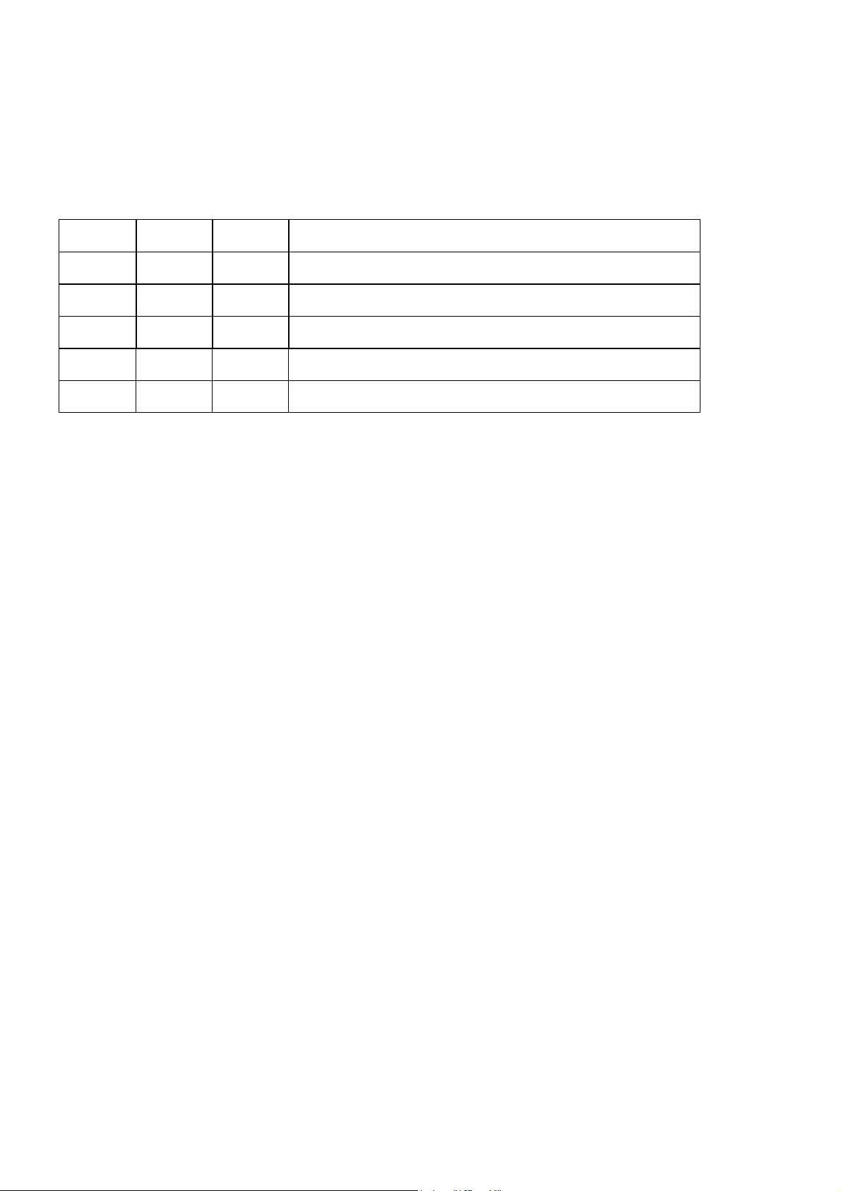
Revision history
Current revision of this document is the uppermost in the table below.
Revision Replaces Date Change Description
2 1 18/03/03 Updated with new Thomson/GVG design.
1 0 28/11/00 New Dip-switch description
0 - 10/10/00 Initial Revision
vii
Page 8

Page 9

CP-UNI Rev. 2
General
The CP-UNI is an X-Y remote control panel for the complete range of Triton routing switchers. All sizes
from 8x8 to 64x64, and also 128x2 can be controlled by a CP-UNI. The panel offers a 16x2 character
alphanumerical display with background light allowing the user to program 16 characters for both inputs
and outputs. The display information is to be downloaded from a PC using the UNI-Soft programming
tool. The UNI-Soft program is part of each CP-UNI delivery.
Inputs and outputs are selected via UP / DOWN keys. Automatic stepping on those keys gives fast access
even on bigger routing systems. 8 LEVEL keys allow addressing of 8 different matrix systems in one
MIDI bus system. Each level allows separate or married control of video and audio indicated by the red
light for audio and the green light for video. 6 FUNCTION keys are provided for different programming
functions. On the left-hand side the panel provides 2 function keys with following functions:
• TAKE Executes the last operation
• ENABLE Enables panel
1.1 Front panel drawing
Take Input select Display Output select
Panel Enable Level select Function keys
1.2 Connection drawing
RJ-45 (NCB
NCB
Power connector RS-232 port
1
) Configuration switches
1
Network Control Bus. The protocol of this bus is equal, and compatible to the MIDI bus protocol.
The user may connect to the bus with RJ-45 or MIDI connectors, but only 1 “IN” and 1 “OUT” may be
connected.
1
Page 10

CP-UNI Rev. 2
2 Power connection
Do not connect mains to the desktop power supply before connecting the power supply to the
router.
Connect the DB9 female connector from the desktop power supply to the main unit. Tighten the screws to
assure a proper contact. To connect mains to the desktop power supply you need a mains cord with IEC
320 connector.
The CP-UNI is normally delivered with the desktop power model AC ±5V / 10W. Upon customer
request, CP-UNI can also be delivered with DC ±5V / 30W, which may be fed by a 36 – 72 VDC mains
power source. A Frame mounted power supply solution is also available.
Please refer to the latest Triton Product Catalogue for power supply types, or call Thomson Grass Valley
for this information.
If any third party power supply is used the CP-UNI requires +5V DC with a minimum current of 200mA.
The following pin-out is used on the DB9 male power connector:
Pin 1 0V
Pin 2 +5V
3 Connecting the CP-UNI to your PC
For connection to a PC with Triton Router Control System, the RS-232 interface is used. The RS-232 port
on all Triton devices uses the standard DCE pin-out, see pin-out table under 4.3.
A standard modem cable can be used for connecting the panel to the PCs serial port.
3.1 Selection of router level
The panel level depends on the system configuration the panel is going to work with. See chapter 5 for
more information. All panels and routers are delivered with default level 1. Triton Router Control System
offers the control of up to 16 different levels of routers, or combinations of routers.
3.2 Pin-out of RS-232 connector
The DB9 female connector for the RS-232 port has the following pin-out:
Pin 2 Tx
Pin 3 Rx
Pin 5 GND
3.3 Maximum cable length
The maximum cable length for an RS-232 connection is per definition 15m. Longer distances can be
installed depending on the environmental conditions of the installation site. It is the responsibility of the
installer / user to secure a proper installation of the RS-232 connection.
2
Page 11

CP-UNI Rev. 2
4 NCB connection
Via the Network Control Bus system several routers and control panels can be interconnected. CP-UNI
utilises MIDI and/or RJ-45 connectors for connecting to the NCB.
Up to 16 levels of routers, or combinations of routers, can be controlled from the Triton - Router Control
System. The NCB system and all RS-232 ports interchange the system status. This means that any control
system, either from Triton, or from a third party manufacturer, connected to any RS-232 port in the NCB
loop, will have access to all communication data on the bus.
4.1 Control bus structure
The Network Control Bus follows the standard MIDI bus definition. The NCB is defined as a closed
chain of units. This means that the NCB OUT of the last unit must be connected to the NCB IN of the
first unit in the NCB chain. To avoid problems with the control of Triton units the installer/user has to
assure that the bus structure is installed according to this definition. The total number of Triton devices in
an NCB chain is limited to 20.
4.2 Maximum distance between NCB devices
The standard MIDI definition allows a maximum cable length of 250 meters between two devices. To
avoid grounding problems all NCB ports have opto-coupled inputs.
4.3 Several routers in one system
The NCB system allows the interconnection of up to 16 routers with different levels in one system. A
combination of routers working married counts as one level. This might for example be 1 audio router + 1
video router working as an audio follows video routing system, or 3 video routers working as 1 RGB
(YUV) routing system. All routers in such a constellation must be configured to the same level.
4.4 Connecting control panels
To get a control panel working with a specific router, configure the control panel to the same level as the
router. Several panels can be configured to control the same router. The CP-UNI can control 2 levels with
breakaway function. If it is necessary to control more levels with breakaway an additional panel must be
used. Panels can also be connected to a router via the RS-232 interface. See hereunder for
connection details.
3
Page 12

CP-UNI Rev. 2
4.5 Pin-out and cable type
4.5.1 RJ45 connectors
On some Triton devices, the NCB cable can be connected to RJ-45 connectors. The following pin-out is
used:
Pin 1 = Not Connected
Pin 2 = Not Connected
Pin 3 = Not Connected
Pin 4 = data
Pin 5 = data
Pin 6 = Not Connected
Pin 7 = Not Connected
Pin 8 = Not Connected
4.5.2 5-pin DIN connectors
However, on Triton devices that use MIDI connectors to connect to the NCB, these connectors follow the
standard MIDI specification. A 1:1 cable with 5pin DIN connector is used. The following pin-out is used:
Pin 1 = Not Connected
Pin 2 = shield
Pin 3 = Not Connected
Pin 4 = data
Pin 5 = data
The standard MIDI specification recommends the use of shielded twisted pair cable types for
interconnection between the units.
4
Page 13

CP-UNI Rev. 2
4.5.3 RJ45 to 5-pin DIN converter
In configurations that include both devices with RJ45 connectors, and devices with 5-pin DIN connectors,
an RJ45 to 5-pin DIN converter may be used to complete the control loop. This converter holds both
connector types, and may work both ways, thus from RJ45 to 5-pin DIN, as well as from 5-pin DIN to
RJ45.
The converter is connected as follows:
RJ45 (Router/CP) RJ45 (Converter) 5-pin DIN (Converter) 5-pin DIN (Router/CP)
IN IN IN OUT
OUT OUT OUT IN
4.6 Control Bus configuration notes
In order to achieve a system that is easy to maintain and control, follow the important notes, presented
hereunder.
• Avoid using routers of different size, but same signal type (audio/video), on the same level.
Example: Do not configure a system with a BVS-1616 and a BVS-0808 on the same level. If they
were on the same level, crosspoint commands that were sent to the BVS-1616 lying outside the
range of the BVS-0808 would not be executed; the BVS-0808 would throw them off the bus.
However, a combination of a BVS-1616 and an BAS-0808 will work well, because commands are
different for video- and audio routers.
• Try to limit the number of devices on one Control Bus loop. If possible, separate systems that are
not to be controlled by one central control panel.
If you need to have several systems in one loop, try to separate as follows, using the DIP switches
on the rear of the devices:
o Analogue Video + Analogue Audio + CP for analogue system on Level 1
o SDI + AES/EBU + CP for digital system on Level 2
o RS-422 Data + CP for data on Level 3
o Universal Control Panel to control all devices above, with user configurable default level.
• Pay attention to the figure below, in order to achieve full controllability of all devices in the loop.
5
Page 14

CP-UNI Rev. 2
Triton - RCS
• Complete the Control loop, by connecting all Control bus connections to all Triton devices, before
powering up any Triton device.
6
Page 15

CP-UNI Rev. 2
5 Control panel configuration
5.1 Pre-set default level
The second Dip-switch Block from the left, SW2 (8 user switches):
At power-up the panel will do a presence check for routers on the pre-set default level. The pre-set
default level can be defined on configuration switch A (leftmost).
Please set the pre-set default level to the address of the routing system you would like to start working
with after powering up CP-UNI
Switches 1 – 3 (from left) on the configuration switch set the control panels level for communication with
the other units in the NCB system. The panels on the NCB dedicated to operate with a specific router
have to be configured to the same level.
Note that although the Triton routers may be configured up to 16 levels, the Triton control panels may
only be configured up to 8 levels. Levels 9 – 16 must be controlled by either Triton - Router Control
System, or by any third party router control system.
The levels can be switched according to the following pattern:
- means switch OFF (down)
* means switch ON (up)
Default level is 1.
Switch 1 2 3 Level
- - - 1
- - * 2
- * - 3
- * * 4
* - - 5
* - * 6
* * - 7
* * * 8
Switch 4 is not in use for this product.
The Dip-switch Blocks, SW1 (8 user switches), and SW3 (4 user switches) are not in use.
7
Page 16

CP-UNI Rev. 2
6 Operating the CP-UNI
6.1 PANEL ENABLE
At power-up the panel will do a presence check for routers on the pre-set default level. If no routers are
present at that level the display will be blank. If a router is detected, the panel will show the status for the
first output. The panel will start in disabled mode. Press the PANEL ENABLE button to start operating.
When the panel is enabled, the button will be green. When disabled, the button will be red. The panel
may be disabled at any time. This will abort any ongoing operation, and the display will return to show
the current status for the selected output at the main-level.
Please note! The panel will not show any status information without being connected to a Triton router
either via MIDI bus or RS-232. In case you do not get any status information please check the interface
cables and re-start the panel.
6.2 TAKE function
The CP-UNI provides a TAKE function. After selecting output and input like described under 4.3 the
TAKE button will start to blink. The crosspoint operation will be executed by pressing the TAKE button.
If you work with video/audio breakaway you can first select the video level, afterwards the audio level
and finally execute both operations at the same time with the TAKE button.
6.3 IN / OUTPUT SELECT
The output to control is selected with the output up/down buttons. Each time a new output is selected, the
current status for that output is also shown in the display. If for some reason the selected output is not
defined in the switcher, the display will show ‘---------‘ for the input. With separate audio/video input
texts, the status is shown only for what is selected – the other is blank. The input to be connected to the
selected output is chosen with the input up/down buttons.
If a source pre-selection is done and no further button is pushed for around 15 seconds the pre-selection
will timeout, the blinking will stop and the display revert to current status. The output selection and input
pre-selection up/down buttons may be held to activate the automatic step-up/step-down. After holding a
button for approx. 1 sec, the auto-step will start at a slow pace. After 3 more seconds, the stepping speed
will increase. This is valid for all operations concerning the step up/down buttons.
6.4 MULTIPLE LEVEL operation
The light in one of the 8 level-buttons indicate which levels are selected at the moment. If there is both
video and audio present on a given level, then it is possible to toggle between either or both selected by
pushing the appropriate level-button. The color will show what is selected – red is audio and green is
video. The LCD display will only show the status of the Main-level, which is the lowest numbered level
selected at any time.
Enabling and disabling levels is done by holding the appropriate level-button for 1-2 seconds. A level
will only become active if at least one switcher is detected on that level. When pushing the input up/down
buttons a new source for the selected output is pre-selected. The pre-selected input for the main-level will
be shown in the display, and the TAKE-button will blink to show that this is a pre-selection – not the
current status. If only video is selected at the main-level, green light in the TAKE-button will blink, and if
only audio – red light.
8
Page 17

CP-UNI Rev. 2
If there is a restriction on a particular output or input-output combination, the Level-buttons will blink
instead of the TAKE-button. By toggling the Level-button of the Main-level, different pre-selections may
be chosen for video and audio (if both are present at the Main-level).
When the source pre-selection is finished and the TAKE-button is blinking, the TAKE-button may be
pushed to execute. If the switcher(s) accept the new status, the TAKE-button will stop blinking. If any
Slave-levels are selected switching messages will be send to these also. If the Main-level has both video
and audio selected, the Slave-levels video will follow the source pre-selection of video Main-level and
similar for audio. If the Main-level has only video or only audio selected, all the selected slave-levels
(video and audio) will be switched to the source number selected at the Main-level.
All the slave-levels will follow the restrictions of the main-level (if any), even if the slave-levels have
stored different restrictions. The restrictions are only checked for the current main-level.
If the main-level is configured for common 16 character input texts and both video and audio is present at
that level, then if the video and audio status are different and both are selected, the video status will be
shown in the display.
6.5 Local programming (size and restrictions)
Entering the Local Programming Mode is done from the panel disabled state. Push and hold the Takebutton and the input up and down buttons. Then push the panel enable button. The display should then
show “Local Program Mode” and the Panel-enable and the Take button should blink in opposite phase.
The programming mode may be aborted at any time by pushing the panel disable button.
Configuring the number of inputs/outputs for each level:
From the Local Program Mode push the F6 button. The second line of the display will toggle between
“A/V Input Common” and “A/V Input Sep.” by pushing the F6 button repeatedly. This selects either the
common 16 character input text or the separate audio/video 8 character input text options.
When the appropriate input text option is selected, select the level number to program by pushing one of
the Level-buttons, which is now blinking. The selected Level-button is now lit, and the display is
showing input and output size 32 (default). The input and output up/down buttons are blinking to indicate
that a different size may be selected. Use the input/output up/down buttons to select the number of inputs
and outputs for the chosen level. When this is finished, push the TAKE-button to store this setting. This
may take a few seconds, and the display will show a message when the operation is completed. This
operation will also store default texts for the chosen level, and remove any restrictions previously stored
for the level. To proceed with another level number, push F6 again and start over.
Configuring the restrictions for outputs or input/output combinations:
From the Local Program Mode push the F1 button. An explanatory text appear in the display, and the
level-buttons start blinking to indicate that the level number has to be chosen.
When the level number is selected, the display will show the restriction status for the first output of that
level. The upper line will show “Restricted:” and then either “None, All or.
Some”, and the lower line will show the name of the output. “None” indicates that no restrictions are
stored for that output, “All” indicates that this output is restricted and “Some” indicates that some inputs
are restricted for that output. Pushing the same level-button repeatedly will toggle the status between
“All” and “None”. This is a quicker way of putting restrictions to a whole output.
9
Page 18

CP-UNI Rev. 2
The output up/down buttons will blink as an indication that a different output may be chosen. When the
appropriate output number is selected the level-button may be used as described above, and/or the input
buttons may be pushed to select individual inputs to place restrictions on.
When an input up/down button is pushed the output up/down buttons stop blinking and the input up/down
buttons start to blink. Restrictions are indicated by blinking level-button and steady lit button indicates no
restriction. Pushing the level-button will toggle the restriction on/off. Repeat for all the required inputs.
When the restrictions for the selected output is complete, push TAKE to store the settings. An
explanatory text will appear in the display, indicating that the restrictions are stored.
Continue with the next output by pushing the output up/down buttons, or select a different level by
pushing F1 again and start from scratch. When setting “All” or “None” restrictions for an output it is no
need to use the input up/down buttons. Just select the output, toggle the setting with the level-button and
push TAKE to store. If changes have been made to one output and another output is selected before
TAKE is pushed, the changes of the previous output will disappear, as it was not stored.
7 Programming Mnemonics with UNI-Soft
7.1 Connection to PC
To be able to download information from the UNI-Soft program to the CP-UNI control panel you need to
connect CP-UNI via it’s RS-232 port to the PC’s serial port. If you use the RS-232 port for connection to
a routing system you have to disconnect this cable while you are programming CP-UNI and re-connect it
after finished programming.
The RS-232 port on all Triton devices uses the standard DCE pin-out, see pin-out below. A standard
modem cable can be used for connecting the router to the PCs serial port. The DB9 female connector for
the RS-232 port has the following pin-out:
Pin 2 Tx
Pin 3 Rx
Pin 5 GND
7.2 How to get started with UNI-Soft
On your CD-R disk you will find a directory UNI-Soft containing the set up for CD installation
SETUPCD. Open directory SETUPCD and run the installation program SETUP.
The UNI-Soft program requires a Pentium PC with at least 100Mhz and Windows 95 / 3.1or NT.
The program requires about 4MB disk space.
UNI-Soft will automatically, during installation, find the next free COM port on your PC.
If you would like to use another COM port please see under chapter 7.4 OPTIONS how to select the
COM port manually.
10
Page 19

CP-UNI Rev. 2
7.3 Main screen
Input slider Input text Output text Output slider
Export button Import button Option menu Status display
UNI-Soft will start-up with 32 in- outputs as default. To change this you have to define the desired router
size under OPTION. Please see chapter 7.4 for reference. On the main screen you can edit both in- and
output text in the white text fields. Selecting in- and outputs is done with the sliders beside the text fields.
Pressing the EXPORT TO DISPLAY button will export the text information and other data generated
under OPTION to the CP-UNI display. The STATUS DISPLAY gives information about the LEVEL, the
router SIZE selected, the COMPORT selected and the filename the set-up will be stored under using
SAVE in the FILE menu.
You can save an unlimited number of set-ups using SAVE AS in the FILE menu. Use OPEN file to get
access to the set-ups you have saved earlier.
Pressing the IMPORT FROM DISPLAY button will import all information stored in the CP-UNI. In case
of any changes please import data from the panel first, make the desired changes and export the revised
data to the panel using the EXPORT TO DISPLAY button.
11
Page 20

CP-UNI Rev. 2
7.4 OPTION button
Pressing OPTION will open a new window, which allows the user to select various user settings.
Number of in/ outputs (router size) Configuring display 16 characters / 8+8 characters
Comport selector Level (address) selector Delete text Generate standard text
You can set the maximum number of in- and outputs (router size) that shall be addressable from CP-UNI
with the sliders on top. Pressing the CONF. OF DISPLAY button will export this information to the
panel. Please note! If you already configured the number in/outputs (router size) on the CP-UNI panel as
described under 4.5 you need to import this data from the panel by pressing the IMPORT FROM
DISPLAY button. Exporting new data from UNI-Soft will overwrite the previous set-up.
With the INPUT=VIDEO button you can select either 16 character string (input=video) or 8+8 character
string (input=video/audio) allowing 8 characters for video and 8 separate characters for audio.
Pressing DELETE ALL TEXTS will delete all text information in the text fields. GENERATE ALL
TEXTS generates a standard text set-up that can be used to start working with CP-UNI.
The level (address) that you want to configure on CP-UNI has to be selected with the LEVEL
SELECTOR. The selected level is shown on the main screen’s status display. The COM port that shall be
used on your PC can be selected with the Comport selector.
12
Page 21

CP-UNI Rev. 2
8 Programming of SALVOS (Pre-sets)
The CP-UNI allows 6 user programmable salvos (pre-sets). The salvos are addressed via the function
buttons F1-F6. The required salvo is pre-selected by pushing the appropriate function button. The display
will change from its normal state and indicate that a salvo is pre-selected. Pushing the TAKE-button
activates the salvo. The display will return to normal when the operation is finished, or if the preselection times out. The salvo is de-selected by pushing the same function button a second time, or a
different salvo may be chosen by pushing another function button.
From the "Local Program Mode" state, push F3 (please see chapter 6.5 for Local Program Mode). The 6
function buttons will start blinking and the display will indicate that the required salvo number must be
chosen. Push any of the F1-F6 buttons to select salvo 1-6.
After selecting the salvo number only this function button will blink. The display will show the content of
location 1 (of 128) for that salvo, and the panel is in "location select mode". A location contains the
following information: Number of location, Video or Audio selection, level (address) number, input
number and output number. Up to 128 locations can be addressed under each salvo. The "location select
mode" is also indicated by the blinking of the output up/down step buttons.
The appropriate location may be chosen by pushing the up/down buttons. The display will show the
location number, "Vid" for video crosspoint set command or "Aud" for audio crosspoint set command,
level number (L), input number (I) and output number (O). Alternatively the location will show
"EMPTY" if the chosen location is unused.
When the location number is chosen, push the appropriate function (salvo) button again. This brings the
panel to the "Clear single location" mode, as indicated by the display. The chosen location may be cleared
by pushing the TAKE-button. If this is done, the location is cleared and the panel returns to the "Location
select mode" so that another location may be chosen.
If the TAKE-button is not pushed, another push on the function (salvo) button enters the "Program
location mode", as indicated by the display. The Level-buttons will also start to blink. Programming of
the selected location is done by first choosing the level number (pushing the appropriate level-button).
The display will change to the same view as for the location select, but this time both the input and output
up/down buttons will blink. These buttons are used for selecting the input-and output number. Video is
chosen as default, but repeated pushing of the level-button will change between video and audio. The
level number may be changed by pushing a different level-button, but in that case the input and output
number will be reset to 1.
When finished, the TAKE-button is used for storing the setting to the chosen location. A text in the
display will show that the setting is stored. Another push on the function (Salvo) button will return the
panel to the "location select mode" for more programming. If programming of the selected location is not
done, another push on the function (salvo) button will bring the panel to the "Clear all locations" mode, as
indicated by the display. If the TAKE-button is pushed in this state all the 128 locations for the selected
salvo number will be cleared. This is the last state, and another push on the salvo button will return the
panel to the "location select mode".
To leave programming of this salvo number, either escape local programming by pushing panel on/off, or
push any other function button to return to the "Local Program Mode".
Note: All buttons are provided with backlight, in addition to the other colors.
13
 Loading...