

Page 1
TRITON routing switcher
Single-Bus Control Panel 32x1
With GPI/Joystick/Tally
Product model no. TTN-CP-32GPI
INSTALLATION MANUAL
MANUAL PART NO. 04-052083-002 Rev. 3
MARCH 18, 2003
the most watched worldwide
Page 2

ii
Headquarters
Thomson Broadcast Systems
17 rue du Petit Albi - BP 8244
95801 Cergy Pontoise Cedex
FRANCE
Copyright 2003 Thomson Broadcast and Media Solutions, Inc. All rights reserved. Grass Valley, Jupiter, and
Triton are trademarks of Thomson. Specifications subject to change without notice.
For customer service, please call (800) 547-8949. For comments or questions concerning this manual, please
contact: Technical Publications Department, P.O. Box 30816, Salt Lake City, Utah 84130 USA. Phone: (801)
972-8000. Fax: (801) 977-1602. Email: SLCtechpubs@THmulti.com
Thomson Broadcast and
Media Solutions, Inc.
P.O. Box 599000
Nevada City, CA 95959-7900
USA
Page 3

iii
Contents
Electromagnetic Radiation Notice iv
Hardware Warranty and Software License v
Parts and Service v
Revision history vi
General 1
1.1 Front panel drawing 1
1.2 Connection drawing 1
2 Power connection 2
3 Connecting the CP-32GPI to your PC 3
3.1 Selection of router level 3
3.2 Pin-out of RS-232 connector 3
3.3 Maximum cable length 3
4 NCB connection 4
4.1 Control bus structure 4
4.2 Maximum distance between NCB devices 4
4.3 Several routers in one system 4
4.4 Connecting control panels 4
4.5 Pin-out and cable type 5
4.5.1 RJ45 connectors 5
4.5.2 5-pin DIN connectors 5
4.5.3 RJ45 to 5-pin DIN converter 6
4.6 Control Bus configuration notes 6
5 Control panel configuration 8
5.1 Panel level 8
5.2 Configuring output 9
5.3 Programming of restrictions 10
6 GPI / Joystick functions 11
6.1 GPI / Joystick mode settings: 11
6.2 Input connector pin-out: 13
6.3 Output connector pin-out: 14
7 Operating the CP-32GPI 15
7.1 PANEL ENABLE button 15
7.2 V/A TOGGLE button 15
7.3 Selecting input 15
7.4 TAKE function 15
Page 4

iv
Electromagnetic Radiation Notice
The following information is given to note compliance with the United States Government Federal Communications
Commission (FCC) Rules (47 CFR Part 15) designed to limit interference to radio and TV reception. The ruling establishes
measurement procedures and frequency criteria for Class A computing devices (commercial and industrial applications) with
the following conduction and radiation limits:
CLASS A COMPUTING DEVICE: CONDUCTION LIMIT (Part 15.812)
Frequency (MHz) Maximum RF Line Voltage (uV)
0.45 - 1.6 1000
1.6 - 30 3000
CLASS A COMPUTING DEVICE: RADIATION LIMIT (Section 15.810)
Frequency (MHz) Distance (meters) Field Strength (uV/m)
30 - 88 30 30
88 - 216 30 50
216 - 1000 30 70
The policy of Thomson is one of continual development and improvement. For that reason Thomson uses components and
manufacturing techniques that provide the current state-of-the-art suppression of electromagnetic radiation. This equipment, in
production before October 1, 1981, has not been tested to the above listed measurements. However, equipment such as this
delivered after October 1, 1983 will have the measurements on record at the factory. Therefore, in compliance with the stated
FCC Regulation, the following information is provided for the user:
NOTE
Interference to Radio Communications
This equipment generates, uses, and can radiate radio frequency energy and if not installed and used
in accordance with the instruction manual, may cause interference to radio communications. As
temporarily permitted by regulation it has not been tested for compliance with the limits for Class A
computing devices pursuant to Subpart J of of Part 15 of FCC Rules, which are designed to provide
reasonable protection against such interference. Operation of this equipment in a residential area
is likely to cause interference in which case the user at his own expense will be required to take
whatever measures may be required to correct the interference.
Page 5

Hardware Warranty and Software License
Please contact your local Thomson representative for
hardware warranty and software license information.
Parts and Service
Thomson maintains a full stock of replacement parts available for immediate shipment.
v
NORTH AMERICA PARTS AND SERVICE
Please call toll-free 1-800-547-8949.
You will be switched automatically to the parts and service representative nearest you.
For email correspondence: broadcast-support@thmulti.com
Internet: http://www.thomsongrassvalley.com
INTERNATIONAL PARTS AND SERVICE
Contact your Thomson representative.
Page 6
vi
Revision history
Current revision of this document is the uppermost in the table below.
Revision Replaces Date Change Description
3 2 18/03/03 Updated with new Thomson/GVG design.
2 1 22/01/01 Corrected Drawing of Front and Rear side.
1 0 18/12/00 New Dip-switch description.
0 - 10/10/00 Initial Revision.
Page 7
CP-32GPI Rev. 3
General
The CP-32GPI is a single-bus remote control panel for the Triton series routing switchers. The panel
offers input select buttons on the top row. The input buttons have different colors for displaying both
video and audio status during breakaway operations. The panel works hardware addressed on one of the
routers outputs. The last selected output will be indicated with color in the button. On the left-hand side
the panel provides 4 function keys with following functions:
• TAKE Executes the last operation
• TAKE ON/OFF Enables / disables Take function
• AUDIO / VIDEO Enables Audio, Video or AFV
• ENABLE Enables panel
The GPI part of the panel has 32 inputs for connection to external relays contacts, joystick or similar. The
GPI outputs (Tally) provide 32 lamp drivers reflecting the status of the video level. Please see chapter 6
for further information.
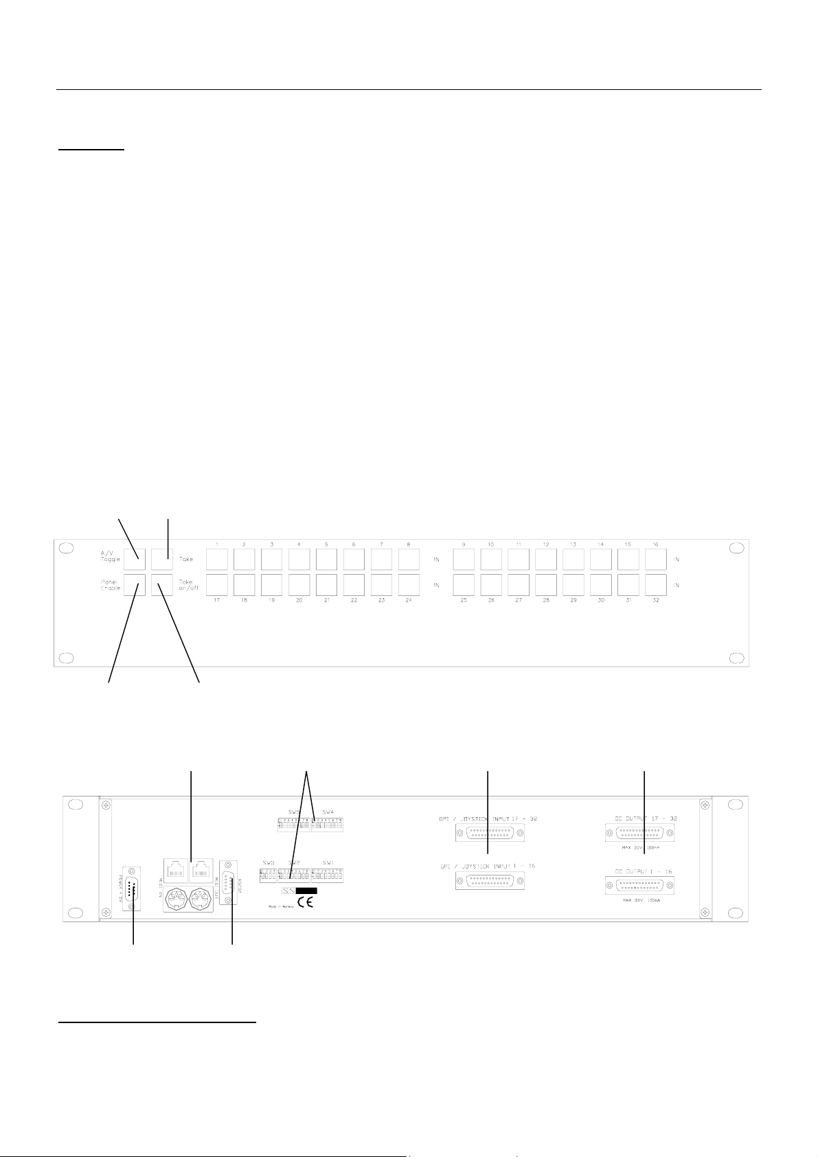
1.1 Front panel drawing
A/V Toggle Take Input buttons
Panel Enable Take ON/OFF
1.2 Connection drawing
RJ-45 (NCB
1
) Configuration switches GPI inputs GPI outputs
NCB
Power connector RS-232 port
1
Network Control Bus. The protocol of this bus is equal, and compatible to the MIDI bus protocol.
The user may connect to the bus with RJ-45 or MIDI connectors, but only 1 “IN” and 1 “OUT” may be
connected.
1
Page 8

CP-32GPI Rev. 3
2 Power connection
Do not connect mains to the desktop power supply before connecting the power supply to the
router.
Connect the DB9 female connector from the desktop power supply to the main unit. Tighten the screws to
assure a proper contact. To connect mains to the desktop power supply you need a mains cord with IEC
320 connector.
The CP-32GPI is normally delivered with the desktop power model AC ±5V / 10W. Upon customer
request, CP-32GPI can also be delivered with DC ±5V / 30W, which may be fed by a 36 – 72 VDC
mains power source. A Frame mounted power supply solution is also available.
Please refer to the latest Triton Product Catalogue for power supply types, or call Thomson Grass Valley
for this information.
If any third party power supply is used the CP-32GPI requires +5V DC with a minimum current of
200mA. The following pin-out is used on the DB9 male power connector:
Pin 1 0V
Pin 2 +5V
2
Page 9

CP-32GPI Rev. 3
3 Connecting the CP-32GPI to your PC
For connection to a PC with Triton Router Control System, the RS-232 interface is used. The RS-232 port
on all Triton devices uses the standard DCE pin-out, see pin-out table under 4.3.
A standard modem cable can be used for connecting the panel to the PCs serial port.
3.1 Selection of router level
The panel level depends on the system configuration the panel is going to work with. See chapter 5 for
more information. All panels and routers are delivered with default level 1. Triton Router Control System
offers the control of up to 16 different levels of routers, or combinations of routers.
3.2 Pin-out of RS-232 connector
The DB9 female connector for the RS-232 port has the following pin-out:
Pin 2 Tx
Pin 3 Rx
Pin 5 GND
3.3 Maximum cable length
The maximum cable length for an RS-232 connection is per definition 15m. Longer distances can be
installed depending on the environmental conditions of the installation site. It is the responsibility of the
installer / user to secure a proper installation of the RS-232 connection.
3
Page 10

CP-32GPI Rev. 3
4 NCB connection
Via the Network Control Bus system several routers and control panels can be interconnected. CP-32GPI
utilises MIDI and/or RJ-45 connectors for connecting to the NCB.
Up to 16 levels of routers, or combinations of routers, can be controlled from the Triton - Router Control
System. The NCB system and all RS-232 ports interchange the system status. This means that any control
system, either from Triton, or from a third party manufacturer, connected to any RS-232 port in the NCB
loop, will have access to all communication data on the bus.
4.1 Control bus structure
The Network Control Bus follows the standard MIDI bus definition. The NCB is defined as a closed
chain of units. This means that the NCB OUT of the last unit must be connected to the NCB IN of the
first unit in the NCB chain. To avoid problems with the control of Triton units the installer/user has to
assure that the bus structure is installed according to this definition. The total number of Triton devices in
an NCB chain is limited to 20.
4.2 Maximum distance between NCB devices
The standard MIDI definition allows a maximum cable length of 250 meters between two devices. To
avoid grounding problems all NCB ports have opto-coupled inputs.
4.3 Several routers in one system
The NCB system allows the interconnection of up to 16 routers with different levels in one system. A
combination of routers working married counts as one level. This might for example be 1 audio router + 1
video router working as an audio follows video routing system, or 3 video routers working as 1 RGB
(YUV) routing system. All routers in such a constellation must be configured to the same level.
4.4 Connecting control panels
To get a control panel working with a specific router, configure the control panel to the same level as the
router. Several panels can be configured to control the same router. The CP-32GPI can control 2 levels
with breakaway function. If it is necessary to control more levels with breakaway an additional panel
must be used. Panels can also be connected to a router via the RS-232 interface. See hereunder for
connection details.
4
Page 11

CP-32GPI Rev. 3
4.5 Pin-out and cable type
4.5.1 RJ45 connectors
On some Triton devices, the NCB cable can be connected to RJ-45 connectors. The following pin-out is
used:
Pin 1 = Not Connected
Pin 2 = Not Connected
Pin 3 = Not Connected
Pin 4 = data
Pin 5 = data
Pin 6 = Not Connected
Pin 7 = Not Connected
Pin 8 = Not Connected
4.5.2 5-pin DIN connectors
However, on Triton devices that use MIDI connectors to connect to the NCB, these connectors follow the
standard MIDI specification. A 1:1 cable with 5pin DIN connector is used. The following pin-out is used:
Pin 1 = Not Connected
Pin 2 = shield
Pin 3 = Not Connected
Pin 4 = data
Pin 5 = data
The standard MIDI specification recommends the use of shielded twisted pair cable types for
interconnection between the units.
5
Page 12

CP-32GPI Rev. 3
4.5.3 RJ45 to 5-pin DIN converter
In configurations that include both devices with RJ45 connectors, and devices with 5-pin DIN connectors,
an RJ45 to 5-pin DIN converter may be used to complete the control loop. This converter holds both
connector types, and may work both ways, thus from RJ45 to 5-pin DIN, as well as from 5-pin DIN to
RJ45.
The converter is connected as follows:
RJ45 (Router/CP) RJ45 (Converter) 5-pin DIN (Converter) 5-pin DIN (Router/CP)
IN IN IN OUT
OUT OUT OUT IN
4.6 Control Bus configuration notes
In order to achieve a system that is easy to maintain and control, follow the important notes, presented
hereunder.
• Avoid using routers of different size, but same signal type (audio/video), on the same level.
Example: Do not configure a system with a BVS-1616 and a BVS-0808 on the same level. If they
were on the same level, crosspoint commands that were sent to the BVS-1616 lying outside the
range of the BVS-0808 would not be executed; the BVS-0808 would throw them off the bus.
However, a combination of a BVS-1616 and an BAS-0808 will work well, because commands are
different for video- and audio routers.
• Try to limit the number of devices on one Control Bus loop. If possible, separate systems that are
not to be controlled by one central control panel.
If you need to have several systems in one loop, try to separate as follows, using the DIP switches
on the rear of the devices:
o Analogue Video + Analogue Audio + CP for analogue system on Level 1
o SDI + AES/EBU + CP for digital system on Level 2
o RS-422 Data + CP for data on Level 3
o Universal Control Panel to control all devices above, with user configurable default level.
• Pay attention to the figure below, in order to achieve full controllability of all devices in the loop.
6
Page 13

CP-32GPI Rev. 3
Triton - RCS
• Complete the Control loop, by connecting all Control bus connections to all Triton devices, before
powering up any Triton device.
7
Page 14

CP-32GPI Rev. 3
5 Control panel configuration
5.1 Panel level
The first Dip-switch Block, top left, SW5 (8 user switches):
Switches 1 – 3 (from left) on the configuration switch set the control panels level for communication with
the other units in the NCB system. The panels on the NCB dedicated to operate with a specific router
have to be configured to the same level.
Note that although the Triton routers may be configured up to 16 levels, the Triton control panels may
only be configured up to 8 levels. Levels 9 – 16 must be controlled by either Triton - Router Control
System, or by any third party router control system.
The levels can be switched according to the following pattern:
- means switch OFF (down)
* means switch ON (up)
Default level is 1.
Switch 1 2 3 Level
- - - 1
- - * 2
- * - 3
- * * 4
* - - 5
* - * 6
* * - 7
* * * 8
Switch 4 is not in use for this product.
8
Page 15

CP-32GPI Rev. 3
5.2 Configuring output
The fourth Dip-switch Block, bottom right, SW1 (8 user switches):
Switches 3 - 8 on the configuration switch define the router output for the control panel. For normal
32x32 operation SW1.3 should always be OFF (down).
The outputs can be switched according to the following pattern:
- means switch OFF (down)
* means switch ON (up)
Default output is 1.
Switch 3 4 5 6 7 8 Output
- - - - - - 1
- - - - - * 2
- - - - * - 3
- - - - * * 4
- - - * - - 5
- - - * - * 6
- - - * * - 7
- - - * * * 8
- - * - - - 9
- - * - - * 10
- - * - * - 11
- - * - * * 12
- - * * - - 13
- - * * - * 14
- - * * * - 15
- - * * * * 16
- * - - - - 17
- * - - - * 18
- * - - * - 19
- * - - * * 20
- * - * - - 21
- * - * - * 22
- * - * * - 23
- * - * * * 24
- * * - - - 25
- * * - - * 26
- * * - * - 27
- * * - * * 28
- * * * - - 29
- * * * - * 30
- * * * * - 31
- * * * * * 32
* - - - - - 33
9
Page 16

CP-32GPI Rev. 3
* - - - - * 34
* - - - * - 35
* - - - * * 36
* - - * - - 37
* - - * - * 38
* - - * * - 39
* - - * * * 40
* - * - - - 41
* - * - - * 42
* - * - * - 43
* - * - * * 44
* - * * - - 45
* - * * - * 46
* - * * * - 47
* - * * * * 48
* * - - - - 49
* * - - - * 50
* * - - * - 51
* * - - * * 52
* * - * - - 53
* * - * - * 54
* * - * * - 55
* * - * * * 56
* * * - - - 57
* * * - - * 58
* * * - * - 59
* * * - * * 60
* * * * - - 61
* * * * - * 62
* * * * * - 63
* * * * * * 64
5.3 Programming of restrictions
If the Restrictions option is enabled by the user, the previously programmed restrictions will be fetched
from the on-board memory during power-up. New restrictions may be programmed by putting the panel
in “Programming mode”. This is done, starting from Panel Disable state, by pushing and holding “V/A
toggle”, “Take On/Off” and “Take” and then pushing “Panel Enable”. Programming mode is indicated by
blinking “Panel Enable” and “Take”.
All the legal inputs for the selected output are shown by orange light in button. The Legal/Illegal toggle is
done by pushing the appropriate input button. When a new output is selected, the programming of the
previous output is saved in the on-board memory and the old setting of the new output is fetched from the
on-board memory.
After all necessary programming is done, the programming mode is stopped by pushing Panel Disable.
Disabling an output completely is done by disabling all inputs for the given output. When in normal mode
these outputs may be selected for viewing the status, but not controlled.
10
Page 17

CP-32GPI Rev. 3
6 GPI / Joystick functions
Following a power-up the GPI/Joystick panel will control Audio and Video married, and the external
lamp-drivers will reflect the status of the video level. The Audio/Video toggle button may be used to
select either Video only or Audio only. The only case where the external lamp-drivers will reflect the
audio status is when audio only is selected.
6.1 GPI / Joystick mode settings:
The third Dip-switch Block, bottom left, SW2 (8 user switches):
SW 4 - 8 from the left: Selects the default input number 1-32 for Joystick hardset default mode,
and also the default input after power-up for dynamic default mode.
The default input can be switched according to the following pattern:
- means switch OFF (down)
* means switch ON (up)
Switch 4 5 6 7 8 Output
- - - - - 1
- - - - * 2
- - - * - 3
- - - * * 4
- - * - - 5
- - * - * 6
- - * * - 7
- - * * * 8
- * - - - 9
- * - - * 10
- * - * - 11
- * - * * 12
- * * - - 13
- * * - * 14
- * * * - 15
- * * * * 16
* - - - - 17
* - - - * 18
* - - * - 19
* - - * * 20
* - * - - 21
* - * - * 22
* - * * - 23
* - * * * 24
* * - - - 25
* * - - * 26
* * - * - 27
* * - * * 28
* * * - - 29
11
Page 18

CP-32GPI Rev. 3
* * * - * 30
* * * * - 31
* * * * * 32
The second Dip-switch Block, top right, SW4 (8 user switches):
SW4.1: UP: Dynamic default mode. For Joystick mode the default input may be selected by
pushing any of the input-buttons. However after power-up the default input is fetched from
SW2.4 – 2.8 until a new default is selected.
The controlled output is restored from non-volatile memory at power-up.
DOWN: Hardset default mode. Both the controlled output (GPI/Joystick modes) and the
default input (Joystick mode only) are fetched from DIPSW settings. During a Joystick
release situation the hardset default will be chosen.
SW4.2: UP: Release before switch. Used in both GPI and Joystick mode. The activation of a new
input line will have no effect until the previous line is released. If more lines are activated
in sequence, the latest activated one will result in a switching as soon as the previously
active is released.
DOWN: Switch before release. Used in both GPI and Joystick mode. The activation of a
new input line will generate a switching, regardless of how many other lines that are
already set.
SW4.3: UP: GPI mode. Releasing the input lines will keep the previous status. Operation of the
front panel is allowed with any number of active GPI-lines simultaneously.
DOWN: Joystick release mode. When all the input lines are released, a default input
either dynamically chosen or static
(
) is set. The front panel is locked if any of the input
lines are active.
12
Page 19

CP-32GPI Rev. 3
6.2 Input connector pin-out:
Connector type DB25 female.
Input 01 - Pin 12
Input 02 - Pin 24
Input 03 - Pin 23
Input 04 - Pin 10
Input 05 - Pin 09
Input 06 - Pin 21
Input 07 - Pin 20
Input 08 - Pin 07
Input 09 - Pin 06
Input 10 - Pin 18
Input 11 - Pin 17
Input 12 - Pin 04
Input 13 - Pin 03
Input 14 - Pin 15
Input 15 - Pin 14
Input 16 - Pin 01
All inputs are internally connected to +5V via a pull-up resistor. The inputs will be activated when
pulling them to Ground.
Ground is available on the following pins: 2, 5, 8, 11, 13, 16, 19, 22, 25 and on the connector chassis.
13
Page 20

CP-32GPI Rev. 3
6.3 Output connector pin-out:
Connector type DB25 female.
Output 01 - Pin 12
Output 02 - Pin 24
Output 03 - Pin 23
Output 04 - Pin 10
Output 05 - Pin 09
Output 06 - Pin 21
Output 07 - Pin 20
Output 08 - Pin 07
Output 09 - Pin 06
Output 10 - Pin 18
Output 11 - Pin 17
Output 12 - Pin 04
Output 13 - Pin 03
Output 14 - Pin 15
Output 15 - Pin 14
Output 16 - Pin 01
The GPI outputs are of open collector type. An output can switch a maximum load of 100mA at 30V.
Any device to be controlled by the GPI outputs (lamp, LED or similar) needs to be connected to an
external supply voltage on one end and to the GPI output on the other end.
Warning ! Do not connect external supply voltages higher than 30V DC.
14
Page 21

CP-32GPI Rev. 3
7 Operating the CP-32GPI
7.1 PANEL ENABLE button
After powering-up the control panel will be disabled. Press the PANEL ENABLE button to start
operating. If you want to lock the control panel after use you simply disable by operating the PANEL
ENABLE button once again.
Please note! The panel will not show any status information without being connected to a Triton router
either via NCB or RS-232. In case you do not get any status information please check the interface cables
and re-start the panel by pressing PANEL ENABLE 2x.
7.2 V/A TOGGLE button
After powering-up the control panel will operate audio follow video. The V/A TOGGLE button is
illuminated. By operating the V/A toggle button you can select the layer you want to switch. Red colour
means only audio. Green colour means only video. Orange colour means audio follow video.
7.3 Selecting input
You select the input you want to operate on the INPUT BUTTON row. The crosspoint operation will be
executed when pressing the input button. The panel updates the button after receiving an acknowledge
message from the router. If the acknowledge is missing the button will start to blink. In this case please
check the interface connection (NCB or RS-232) and if the router is powered up. In case you press a
button outside the routing area (e.g. when controlling an 8x8 router with a 16x16 panel) the INPUT
BUTTON will start to blink indicating that you try to operate without having access.
7.4 TAKE function
The CP-32GPI provides a TAKE function, which can be activated by pressing the TAKE ON/OFF
button. The TAKE ON/OFF button will show green light if the TAKE function is activated. After
selecting input, as described above, the INPUT button and the TAKE button will start to blink. The
crosspoint operation will be executed by pressing the TAKE button. If you work with video/audio
breakaway you can first select the video layer, afterwards the audio layer and finally execute both
operations at the same time with the TAKE button.
Note: All buttons are provided with backlight in addition to the other colours.
15
 Loading...