

Page 1

applicability
All Triton switchers controlled by a Jupiter Control System.
purpose
These instructions describe installation of the
supplied with this kit.
materials required
Triton to Jupiter Serial Control Kit
Product part no. 44–050456–001
Installation Instructions
Document Part Number 04–051254–001 Rev C
March 7, 2003
B&B Electronics RS–232 to RS–422 Converter
procedure
Kit, VM 3000 To Triton Control 44–050456–001
DESCRIPTION
B&B Elect. 422COR RS–232/422 Converter 06–050454–001 1
B&B Electronics BB–33 Universal Power Supply 06–050455–001 1
VM 3000 to Converter Cable, 25 ft. (7.6 m) 01–050452–001 1
Converter to Triton Cable, 25 ft. (7.6 m) 01–050453–001 1
Installation Instructions 04–051254–001 1
Other items required:
Volt/ohmmeter — not supplied in kit
AC line plug adapter (for installations outside North America) — not supplied in kit
1. Set the AC voltage switch on the Universal Power Supply to the correct voltage for your
country (110 V or 220 V).
Note: The default setting is 110 V.
PART NUMBER QTY
2. Set the Polarity switch on the Universal Power Supply to the positive position.
3. Set the DC voltage switch on the Universal Power Supply to the 12 volt position.
Page 2
2
Note that the DC voltage switch is continuously variable and that the voltage level labels
are approximate.
4. Plug the BB–33 Universal Power Supply into AC power. Measure the DC voltage on
the output. Adjust the DC voltage switch until a 12 VDC reading is obtained.
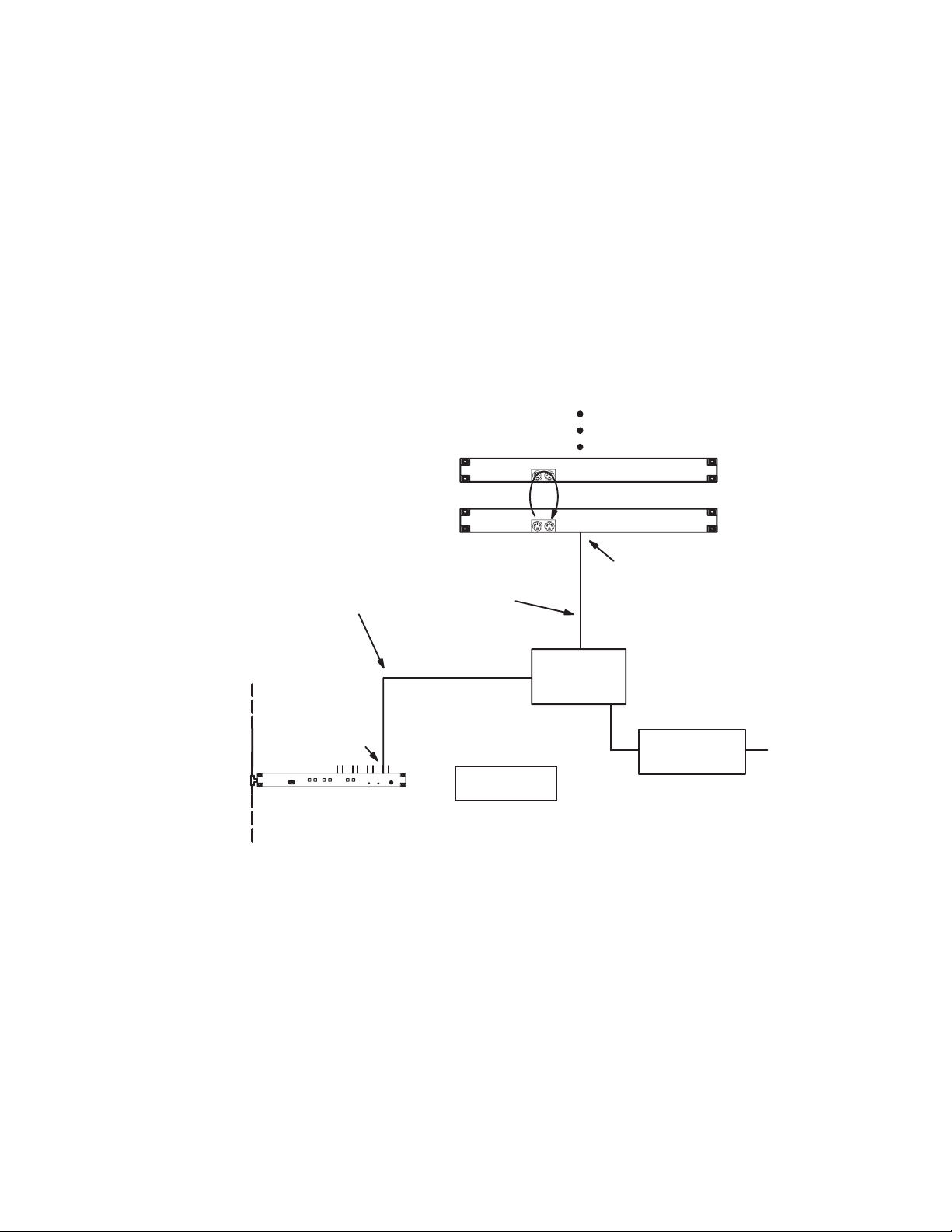
5. Connect the VM 3000 to Converter Cable, part number 01–050452–001, to an odd
number serial port on the VM 3000. See Figure 1.
Note 1: The even numbered ports on the VM 3000 will not work for this application.
Note 2: The SI–3000 will not support Triton control.
20 units maximum
Triton L + R Audio
Triton Video
VM 3000 to
Converter
Cable
Serial port
VM 3000 Control Processor
LAN
MIDI bus loop
RS–232 port
Converter to
Triton cable
B&B
RS–232/422
Triton protocol
Triton protocol avail-
able on odd–num-
bered ports only
Figure 1. Example of connection to Triton distribution switchers.
Converter
B&B Universal
Power Supply
Router address “0”
Router address “2”
AC line
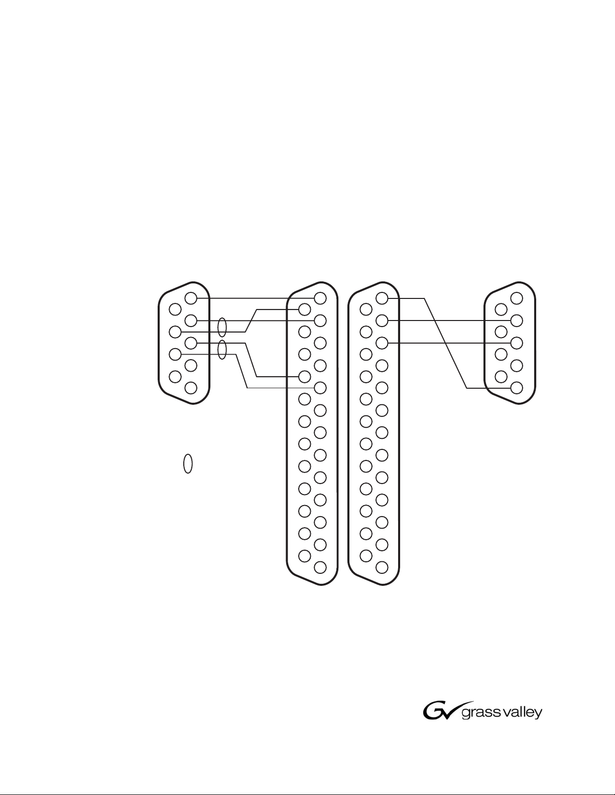
6. Connect the 25–pin end of the VM 3000 to Converter Cable to the RS–422 side of the
B&B converter. (Pinouts for this cable are shown in Figure 2.)
7. Connect the 9–pin end of the Converter to Triton Cable, part number
01–050453–001, to the RS–232 port on the Triton switcher.
8. Connect the 25–pin end of the Converter to Triton Cable to the RS–232 side of the
B&B converter.
9. With the power supply disconnected from AC power, connect the DC power connector
on the Universal Power Supply to the 12 VDC connector on the B&B Electronics RS
232 / RS 422 Converter.
Page 3
3
2003 Thomson Broadcast & Media Solutions, Inc. All rights reserved. All specifications subject to change without notice. GV and
uh-
10. Connect the Universal Power Supply to AC power.
Note 1: A plug adapter may be required for use outside of North America.
Note 2: In redundant VM installations, remeasure the converter power supply output to be sure it is at 12 volts. This is necessary because of the increased cable loading.
11. The Triton hardware connection is now complete. The Jupiter configuration tables must
be modified to include the Triton switcher. Refer to the Jupiter Facility Control System
Installation and Operating manual, part number 04–045707–002, for information on
configuration for control of Triton switchers.
to VM 3000
serial port
1
G
6
2
R–
7
R+
3
T+
8
T–
4
9
5
DB9P
(male)
= twisted pair
G Ground
R– Receive minus
R+ Receive plus
T+ Transmit plus
T– Transmit minus
DB25S
(female)
14
T+
15
16
17
R+
18
19
20
21
22
23
24
25
to RS–422/232
converter
1
G
T–
R–
14
2
15
3
16
4
17
5
18
6
19
7
20
8
21
9
22
10
23
11
24
12
25
13
to Triton
RS–232 Port
Tx
Rx
G
DB9P
(male)
1
2
3
4
5
1
G
2
Rx
3
Tx
4
5
6
7
8
6
7
8
9
G Ground
9
10
11
12
13
Rx Receive
Tx Transmit
Figure 2. Cables for connecting
VM 3000, Converter, and Triton.
DB25P
(male)
©
Grass V alley are trademarks of Thomson. F or customer service, please call (800) 547–8949. For comments or questions concerning this doc
ment, contact: Technical Publications Department, P.O. Box 30816, Salt Lake City, Utah 84130. Phone: (801) 972–8000. Email: SLCtec
pubs@thmulti.com
 Loading...