

Page 1

Trinix NXT
DIGITAL VIDEO ROUTER
Installation and Service Manual
Software Version 3.3.1
071827613
OCTOBER 2011
Page 2

CERTIFICATE
Certificate Number: 510040.001
The Quality System of:
Grass Valley USA, LLC and its Grass Valley Affiliates
Headquarters:
400 Providence Mine Road
Nevada City, CA 95945
United States
15655 SW Greystone Ct.
Beaverton, OR 97006
United States
Brunnenweg 9
D-64331 Weiterstadt
Germany
Kapittelweg 10
4827 HG Breda
The Nederlands
2300 So. Decker Lake Blvd.
Salt Lake City, UT 84119
United States
Including its implementation, meets the requirements of the standard:
ISO 9001:2008
Scope:
The design, manufacture and support of video and audio hardware and software products and related
systems.
This Certificate is valid until: June 14, 2012
This Certificate is valid as of: December 23, 2010
Certified for the first time: June 14, 2000
H. Pierre Sallé
President
KEMA-Registered Quality
The method of operation for quality certification is defined in the KEMA General Terms And Conditions For
Quality And Environmental Management Systems Certifications. Integral publication of this certificate is allowed.
KEMA-Registered Quality, Inc.
4377 County Line Road
Chalfont, PA 18914
Ph: (215)997-4519
Fax: (215)997-3809
CRT 001 042108
ccredited By:
ANAB
A
Page 3

Trinix NXT
DIGITAL VIDEO ROUTER
Installation and Service Manual
Software Version 3.3.1
071827613
OCTOBER 2011
Page 4

Contacting Grass Valley
International
Support Centers
Local Support
Centers
(available
during normal
business hours)
France
24 x 7
Australia and New Zealand: +61 1300 721 495 Central/South America: +55 11 5509 3443
Middle East: +971 4 299 64 40 Near East and Africa: +800 8080 2020 or +33 1 48 25 20 20
Europe
+800 8080 2020 or +33 1 48 25 20 20
Hong Kong, Taiwan, Korea, Macau: +852 2531 3058 Indian Subcontinent: +91 22 24933476
Asia
Southeast Asia/Malaysia: +603 7805 3884 Southeast Asia/Singapore: +65 6379 1313
China: +861 0660 159 450 Japan: +81 3 5484 6868
Belarus, Russia, Tadzikistan, Ukraine, Uzbekistan: +7 095 2580924 225 Switzerland: +41 1 487 80 02
S. Europe/Italy-Roma: +39 06 87 20 35 28 -Milan: +39 02 48 41 46 58 S. Europe/Spain: +34 91 512 03 50
Benelux/Belgium: +32 (0) 2 334 90 30 Benelux/Netherlands: +31 (0) 35 62 38 42 1 N. Europe: +45 45 96 88 70
Germany, Austria, Eastern Europe: +49 6150 104 444 UK, Ireland, Israel: +44 118 923 0499
Copyright © Grass Valley USA, LLC. All rights reserved.
This product may be covered by one or more U.S. and foreign patents.
United States/Canada
24 x 7
+1 800 547 8949 or +1 530 478 4148
Grass Valley Web Site
The www.grassvalley.com web site offers the following:
Online User Documentation — Current versions of product catalogs, brochures,
data sheets, ordering guides, planning guides, manuals, and release notes
in .pdf format can be downloaded.
FAQ Database — Solutions to problems and troubleshooting efforts can be
found by searching our Frequently Asked Questions (FAQ) database.
Software Downloads — Download software updates, drivers, and patches.
4 Trinix NXT — Installation and Service Manual
Page 5

Contents
Section 1 — Introduction. . . . . . . . . . . . . . . . . . . . . . . . . . . . . . . . . . . . . . . . . . . . . . . . 31
About This Manual . . . . . . . . . . . . . . . . . . . . . . . . . . . . . . . . . . . . . . . . . . . . . . . . . . . . . 9
Additional Documentation . . . . . . . . . . . . . . . . . . . . . . . . . . . . . . . . . . . . . . . . . . . . 9
Safety Terms and Symbols. . . . . . . . . . . . . . . . . . . . . . . . . . . . . . . . . . . . . . . . . . . . . . 11
Terms in This Manual. . . . . . . . . . . . . . . . . . . . . . . . . . . . . . . . . . . . . . . . . . . . . . . . 11
Terms on the Product . . . . . . . . . . . . . . . . . . . . . . . . . . . . . . . . . . . . . . . . . . . . . . . . 11
Symbols on the Product . . . . . . . . . . . . . . . . . . . . . . . . . . . . . . . . . . . . . . . . . . . . . . 12
Warnings . . . . . . . . . . . . . . . . . . . . . . . . . . . . . . . . . . . . . . . . . . . . . . . . . . . . . . . . . . . . 12
Cautions . . . . . . . . . . . . . . . . . . . . . . . . . . . . . . . . . . . . . . . . . . . . . . . . . . . . . . . . . . . . . 13
Certifications and Compliances . . . . . . . . . . . . . . . . . . . . . . . . . . . . . . . . . . . . . . . . . 23
FCC Emission Control . . . . . . . . . . . . . . . . . . . . . . . . . . . . . . . . . . . . . . . . . . . . . . . 23
Canadian EMC Notice of Compliance . . . . . . . . . . . . . . . . . . . . . . . . . . . . . . . . . . 23
EN 55103 Class A Warning . . . . . . . . . . . . . . . . . . . . . . . . . . . . . . . . . . . . . . . . . . . 23
Canadian Certified Power Cords . . . . . . . . . . . . . . . . . . . . . . . . . . . . . . . . . . . . . . 24
Canadian Certified AC Adapter . . . . . . . . . . . . . . . . . . . . . . . . . . . . . . . . . . . . . . . 24
Laser Compliance . . . . . . . . . . . . . . . . . . . . . . . . . . . . . . . . . . . . . . . . . . . . . . . . . . . 24
Certification . . . . . . . . . . . . . . . . . . . . . . . . . . . . . . . . . . . . . . . . . . . . . . . . . . . . . . . . 25
Recommended ESD Guidelines . . . . . . . . . . . . . . . . . . . . . . . . . . . . . . . . . . . . . . . . . 27
Sources of ESD and Risks. . . . . . . . . . . . . . . . . . . . . . . . . . . . . . . . . . . . . . . . . . . . . . . 28
Grounding Requirements for Personnel . . . . . . . . . . . . . . . . . . . . . . . . . . . . . . . . . . 29
General . . . . . . . . . . . . . . . . . . . . . . . . . . . . . . . . . . . . . . . . . . . . . . . . . . . . . . . . . . . . 31
SD, HD, and 3GB/s in the Same Frame . . . . . . . . . . . . . . . . . . . . . . . . . . . . . . . . . 32
Easy to Create Very Large Routers. . . . . . . . . . . . . . . . . . . . . . . . . . . . . . . . . . . . . 33
Control Systems. . . . . . . . . . . . . . . . . . . . . . . . . . . . . . . . . . . . . . . . . . . . . . . . . . . . . 33
The Symmetric Trinix Frame . . . . . . . . . . . . . . . . . . . . . . . . . . . . . . . . . . . . . . . . . . 33
The Asymmetric Frame . . . . . . . . . . . . . . . . . . . . . . . . . . . . . . . . . . . . . . . . . . . . . . 34
Trinix Architecture . . . . . . . . . . . . . . . . . . . . . . . . . . . . . . . . . . . . . . . . . . . . . . . . . . 34
Serviceability and Reliability . . . . . . . . . . . . . . . . . . . . . . . . . . . . . . . . . . . . . . . . . . 35
Broadlinx. . . . . . . . . . . . . . . . . . . . . . . . . . . . . . . . . . . . . . . . . . . . . . . . . . . . . . . . . . . 36
Section 2 — Planning Guide . . . . . . . . . . . . . . . . . . . . . . . . . . . . . . . . . . . . . . . . . . . . 39
Introduction . . . . . . . . . . . . . . . . . . . . . . . . . . . . . . . . . . . . . . . . . . . . . . . . . . . . . . . . . . 39
Trinix Frames. . . . . . . . . . . . . . . . . . . . . . . . . . . . . . . . . . . . . . . . . . . . . . . . . . . . . . . . . 39
Sync Reference Options . . . . . . . . . . . . . . . . . . . . . . . . . . . . . . . . . . . . . . . . . . . . . . 61
Duplication and Expansion . . . . . . . . . . . . . . . . . . . . . . . . . . . . . . . . . . . . . . . . . . . . . 69
Output Duplication - Dual. . . . . . . . . . . . . . . . . . . . . . . . . . . . . . . . . . . . . . . . . . . . 69
Output Duplication - Quad . . . . . . . . . . . . . . . . . . . . . . . . . . . . . . . . . . . . . . . . . . . 74
Expanded Systems. . . . . . . . . . . . . . . . . . . . . . . . . . . . . . . . . . . . . . . . . . . . . . . . . . . 76
Protected Paths . . . . . . . . . . . . . . . . . . . . . . . . . . . . . . . . . . . . . . . . . . . . . . . . . . . . . . . 95
Overview . . . . . . . . . . . . . . . . . . . . . . . . . . . . . . . . . . . . . . . . . . . . . . . . . . . . . . . . . . 95
Planning . . . . . . . . . . . . . . . . . . . . . . . . . . . . . . . . . . . . . . . . . . . . . . . . . . . . . . . . . . . 98
Worksheet for Protected Path Implementation. . . . . . . . . . . . . . . . . . . . . . . . . . 105
Control Systems. . . . . . . . . . . . . . . . . . . . . . . . . . . . . . . . . . . . . . . . . . . . . . . . . . . . . . 106
Jupiter Facility Control System . . . . . . . . . . . . . . . . . . . . . . . . . . . . . . . . . . . . . . . 106
Trinix NXT — Installation and Service Manual 5
Page 6

Contents
SMS 7000 / Encore Control. . . . . . . . . . . . . . . . . . . . . . . . . . . . . . . . . . . . . . . . . . 108
LAN and Com Bus Connections . . . . . . . . . . . . . . . . . . . . . . . . . . . . . . . . . . . . . . . 109
System Monitoring Applications . . . . . . . . . . . . . . . . . . . . . . . . . . . . . . . . . . . . . . . 112
Specifications. . . . . . . . . . . . . . . . . . . . . . . . . . . . . . . . . . . . . . . . . . . . . . . . . . . . . . . . 113
Electrical. . . . . . . . . . . . . . . . . . . . . . . . . . . . . . . . . . . . . . . . . . . . . . . . . . . . . . . . . . 113
Environmental. . . . . . . . . . . . . . . . . . . . . . . . . . . . . . . . . . . . . . . . . . . . . . . . . . . . . 118
Air Flow . . . . . . . . . . . . . . . . . . . . . . . . . . . . . . . . . . . . . . . . . . . . . . . . . . . . . . . . . . 118
Physical . . . . . . . . . . . . . . . . . . . . . . . . . . . . . . . . . . . . . . . . . . . . . . . . . . . . . . . . . . 119
Configuration . . . . . . . . . . . . . . . . . . . . . . . . . . . . . . . . . . . . . . . . . . . . . . . . . . . . . . . 121
Section 3 — Hardware Installation . . . . . . . . . . . . . . . . . . . . . . . . . . . . . . . . . . . 125
Summary of Installation Procedure. . . . . . . . . . . . . . . . . . . . . . . . . . . . . . . . . . . . . 125
Pre-Installation Steps . . . . . . . . . . . . . . . . . . . . . . . . . . . . . . . . . . . . . . . . . . . . . . . 125
Customer-Supplied Rack Requirements. . . . . . . . . . . . . . . . . . . . . . . . . . . . . . . 126
Connecting the Power Supplies . . . . . . . . . . . . . . . . . . . . . . . . . . . . . . . . . . . . . . 126
Connecting and Configuring the Reference Settings . . . . . . . . . . . . . . . . . . . . 128
Configuring Each Output Monitor on the TRX-OPM Boards . . . . . . . . . . . . . 130
Connecting the Cables . . . . . . . . . . . . . . . . . . . . . . . . . . . . . . . . . . . . . . . . . . . . . . 131
Control and Monitoring Systems . . . . . . . . . . . . . . . . . . . . . . . . . . . . . . . . . . . . . 131
Optional Connections. . . . . . . . . . . . . . . . . . . . . . . . . . . . . . . . . . . . . . . . . . . . . . . 132
Powering Up the Routing Switcher . . . . . . . . . . . . . . . . . . . . . . . . . . . . . . . . . . . 133
Setting the Rear Panel Dip Switch . . . . . . . . . . . . . . . . . . . . . . . . . . . . . . . . . . . . . 148
Power Supply Notes . . . . . . . . . . . . . . . . . . . . . . . . . . . . . . . . . . . . . . . . . . . . . . . . . 151
Sync Reference Connections. . . . . . . . . . . . . . . . . . . . . . . . . . . . . . . . . . . . . . . . . . . 157
NR/SR-33000 / SR-33500/ TRX-SR V-Phasing . . . . . . . . . . . . . . . . . . . . . . . . . . . 170
Output Board Configuration . . . . . . . . . . . . . . . . . . . . . . . . . . . . . . . . . . . . . . . . . . 185
Duplication and Expansion . . . . . . . . . . . . . . . . . . . . . . . . . . . . . . . . . . . . . . . . . . . 186
Output Reclocker Bypass Settings. . . . . . . . . . . . . . . . . . . . . . . . . . . . . . . . . . . . . . 197
Input Equalization Settings. . . . . . . . . . . . . . . . . . . . . . . . . . . . . . . . . . . . . . . . . . . . 199
Output Monitoring. . . . . . . . . . . . . . . . . . . . . . . . . . . . . . . . . . . . . . . . . . . . . . . . . . . 200
Monitoring with Expanded Systems . . . . . . . . . . . . . . . . . . . . . . . . . . . . . . . . . . 207
Frame Number Settings. . . . . . . . . . . . . . . . . . . . . . . . . . . . . . . . . . . . . . . . . . . . . . . 212
Jupiter Control . . . . . . . . . . . . . . . . . . . . . . . . . . . . . . . . . . . . . . . . . . . . . . . . . . . . . . 214
SMS 7000 / Encore Control. . . . . . . . . . . . . . . . . . . . . . . . . . . . . . . . . . . . . . . . . . . . 219
LAN and Com Bus Connections . . . . . . . . . . . . . . . . . . . . . . . . . . . . . . . . . . . . . . . 221
Replacing Trinix Boards . . . . . . . . . . . . . . . . . . . . . . . . . . . . . . . . . . . . . . . . . . . . . . 226
Section 4 — Trinix Asymmetrical Power Supply Configurations . . . 227
Introduction. . . . . . . . . . . . . . . . . . . . . . . . . . . . . . . . . . . . . . . . . . . . . . . . . . . . . . . . . 227
The External Power Supply Frame . . . . . . . . . . . . . . . . . . . . . . . . . . . . . . . . . . . . . 227
The Power Supply Module . . . . . . . . . . . . . . . . . . . . . . . . . . . . . . . . . . . . . . . . . . 228
Basic Configuration for the Lineage Power Supply Frame . . . . . . . . . . . . . . . 230
Trinix Asymmetrical Frames . . . . . . . . . . . . . . . . . . . . . . . . . . . . . . . . . . . . . . . . . . 230
Trinix Status Concentrator Board (TRX-SC). . . . . . . . . . . . . . . . . . . . . . . . . . . . 230
The 128X256 Trinix Asymmetrical Frame. . . . . . . . . . . . . . . . . . . . . . . . . . . . . . . . 233
The 256X512 Trinix Asymmetrical Frame. . . . . . . . . . . . . . . . . . . . . . . . . . . . . . . . 243
The 512X1024 Trinix Asymmetrical Frame. . . . . . . . . . . . . . . . . . . . . . . . . . . . . . . 252
512X1024 Default Power Supply Configuration . . . . . . . . . . . . . . . . . . . . . . . . 254
512X1024 Redundant Power Supply Configurations, Option A . . . . . . . . . . . 257
6 Trinix NXT — Installation and Service Manual
Page 7

Section 5 — Broadlinx Installation . . . . . . . . . . . . . . . . . . . . . . . . . . . . . . . . . . . . 259
Software Installation. . . . . . . . . . . . . . . . . . . . . . . . . . . . . . . . . . . . . . . . . . . . . . . . . . 260
Introduction . . . . . . . . . . . . . . . . . . . . . . . . . . . . . . . . . . . . . . . . . . . . . . . . . . . . . . . 260
Updating Compact Flash Cards . . . . . . . . . . . . . . . . . . . . . . . . . . . . . . . . . . . . . . 261
Updating New Broadlinx Boards . . . . . . . . . . . . . . . . . . . . . . . . . . . . . . . . . . . . . 262
Updating Systems with a Single Broadlinx Board . . . . . . . . . . . . . . . . . . . . . . . 263
Updating Systems with Two Broadlinx Boards . . . . . . . . . . . . . . . . . . . . . . . . . 269
Licensing SNMP on Both Broadlinx Boards . . . . . . . . . . . . . . . . . . . . . . . . . . . . 277
Formatting the Compact Flash Card with the FAT16 Format . . . . . . . . . . . . . 279
Alternate methods for Updating a Compact Flash Cards. . . . . . . . . . . . . . . . . 281
Installation FAQ. . . . . . . . . . . . . . . . . . . . . . . . . . . . . . . . . . . . . . . . . . . . . . . . . . . . 283
Section 6 — Broadlinx Software. . . . . . . . . . . . . . . . . . . . . . . . . . . . . . . . . . . . . . . 285
Configuring the Network Settings . . . . . . . . . . . . . . . . . . . . . . . . . . . . . . . . . . . . 285
Configuration. . . . . . . . . . . . . . . . . . . . . . . . . . . . . . . . . . . . . . . . . . . . . . . . . . . . . . . . 292
Opening the Configuration Page . . . . . . . . . . . . . . . . . . . . . . . . . . . . . . . . . . . . . 292
SNMP/NetCentral Monitoring. . . . . . . . . . . . . . . . . . . . . . . . . . . . . . . . . . . . . . . 300
Licensing SNMP on Both Broadlinx Boards . . . . . . . . . . . . . . . . . . . . . . . . . . . . 309
Broadlinx / Internet Explorer Monitoring. . . . . . . . . . . . . . . . . . . . . . . . . . . . . . 311
Firmware Update. . . . . . . . . . . . . . . . . . . . . . . . . . . . . . . . . . . . . . . . . . . . . . . . . . . 318
Trinix Matrix Identification from the NetConfig Software. . . . . . . . . . . . . . . . 319
Updating the FPGAs Firmware on Multiple Boards at the Same Time . . . . . 322
Contents
Section 7 — Broadlinx Console Commands . . . . . . . . . . . . . . . . . . . . . . . . . . 329
Section 8 — Broadlinx Version and Supported Trinix Boards . . . . . . . 337
Matrix Controller. . . . . . . . . . . . . . . . . . . . . . . . . . . . . . . . . . . . . . . . . . . . . . . . . . . 338
Matrix . . . . . . . . . . . . . . . . . . . . . . . . . . . . . . . . . . . . . . . . . . . . . . . . . . . . . . . . . . . . 339
Reference. . . . . . . . . . . . . . . . . . . . . . . . . . . . . . . . . . . . . . . . . . . . . . . . . . . . . . . . . . 341
Rear Panel. . . . . . . . . . . . . . . . . . . . . . . . . . . . . . . . . . . . . . . . . . . . . . . . . . . . . . . . . 342
Input . . . . . . . . . . . . . . . . . . . . . . . . . . . . . . . . . . . . . . . . . . . . . . . . . . . . . . . . . . . . . 343
Output. . . . . . . . . . . . . . . . . . . . . . . . . . . . . . . . . . . . . . . . . . . . . . . . . . . . . . . . . . . . 345
Section 9 — Protected Paths . . . . . . . . . . . . . . . . . . . . . . . . . . . . . . . . . . . . . . . . . . 349
Protected Paths Overview . . . . . . . . . . . . . . . . . . . . . . . . . . . . . . . . . . . . . . . . . . . . . 349
Verifying the Parameters on the Broadlinx Boards . . . . . . . . . . . . . . . . . . . . . . . . 352
Broadlinx Software with Protected Paths Installation. . . . . . . . . . . . . . . . . . . . . . 355
Accessing the Protected Path Page . . . . . . . . . . . . . . . . . . . . . . . . . . . . . . . . . . . . 358
Broadlinx Protective Paths Web Page . . . . . . . . . . . . . . . . . . . . . . . . . . . . . . . . . . . 360
Assigning a Secondary Path. . . . . . . . . . . . . . . . . . . . . . . . . . . . . . . . . . . . . . . . . . 365
System Alarm Overview . . . . . . . . . . . . . . . . . . . . . . . . . . . . . . . . . . . . . . . . . . . . 366
Protected Path Alarms . . . . . . . . . . . . . . . . . . . . . . . . . . . . . . . . . . . . . . . . . . . . . . 366
Encore Configuration . . . . . . . . . . . . . . . . . . . . . . . . . . . . . . . . . . . . . . . . . . . . . . . . . 367
Jupiter Configuration . . . . . . . . . . . . . . . . . . . . . . . . . . . . . . . . . . . . . . . . . . . . . . . . . 371
Operation Notes . . . . . . . . . . . . . . . . . . . . . . . . . . . . . . . . . . . . . . . . . . . . . . . . . . . . . 373
Section 10 — Encore Control . . . . . . . . . . . . . . . . . . . . . . . . . . . . . . . . . . . . . . . . . . 375
Encore Control of Trinix. . . . . . . . . . . . . . . . . . . . . . . . . . . . . . . . . . . . . . . . . . . . . 375
Sync Reference . . . . . . . . . . . . . . . . . . . . . . . . . . . . . . . . . . . . . . . . . . . . . . . . . . . . . 377
Trinix NXT — Installation and Service Manual 7
Page 8

Contents
Encore Configuration of Protected Paths . . . . . . . . . . . . . . . . . . . . . . . . . . . . . . 377
Section 11 — Analog Input Processing . . . . . . . . . . . . . . . . . . . . . . . . . . . . . . . 379
TRX-VI-33100 Module . . . . . . . . . . . . . . . . . . . . . . . . . . . . . . . . . . . . . . . . . . . . . . . . 379
Analog Processing Control . . . . . . . . . . . . . . . . . . . . . . . . . . . . . . . . . . . . . . . . . . 379
Customizing Analog Video Processing Settings . . . . . . . . . . . . . . . . . . . . . . . . 380
Section 12 — Troubleshooting . . . . . . . . . . . . . . . . . . . . . . . . . . . . . . . . . . . . . . . . 393
LEDs . . . . . . . . . . . . . . . . . . . . . . . . . . . . . . . . . . . . . . . . . . . . . . . . . . . . . . . . . . . . . 393
Signal flow . . . . . . . . . . . . . . . . . . . . . . . . . . . . . . . . . . . . . . . . . . . . . . . . . . . . . . . . 410
Incompatible Switches. . . . . . . . . . . . . . . . . . . . . . . . . . . . . . . . . . . . . . . . . . . . . . . . 414
Section 13 — Trinix Fiber Option . . . . . . . . . . . . . . . . . . . . . . . . . . . . . . . . . . . . . 415
Trinix Fiber Boards Overview . . . . . . . . . . . . . . . . . . . . . . . . . . . . . . . . . . . . . . . . . 415
Fiber Optic Cleaning Requirement . . . . . . . . . . . . . . . . . . . . . . . . . . . . . . . . . . . 416
Specifications. . . . . . . . . . . . . . . . . . . . . . . . . . . . . . . . . . . . . . . . . . . . . . . . . . . . . . . . 419
LED Displays. . . . . . . . . . . . . . . . . . . . . . . . . . . . . . . . . . . . . . . . . . . . . . . . . . . . . . 421
Trinix Fiber Boards Installation . . . . . . . . . . . . . . . . . . . . . . . . . . . . . . . . . . . . . . . . 424
Installing the Trinix Fiber Option. . . . . . . . . . . . . . . . . . . . . . . . . . . . . . . . . . . . . 425
Section 14 — Front-Air Vent. . . . . . . . . . . . . . . . . . . . . . . . . . . . . . . . . . . . . . . . . . . 429
Front-Air Vent (FAV) Overview . . . . . . . . . . . . . . . . . . . . . . . . . . . . . . . . . . . . . . . 429
Installation Procedure . . . . . . . . . . . . . . . . . . . . . . . . . . . . . . . . . . . . . . . . . . . . . . . . 431
Installing the FAV. . . . . . . . . . . . . . . . . . . . . . . . . . . . . . . . . . . . . . . . . . . . . . . . . . 431
Section 15 — Trinix Frame Slot Maps . . . . . . . . . . . . . . . . . . . . . . . . . . . . . . . . 433
Trinix 512x512 Frame Slot Numbers . . . . . . . . . . . . . . . . . . . . . . . . . . . . . . . . . . 434
Trinix 256x256 Frame Slot Numbers . . . . . . . . . . . . . . . . . . . . . . . . . . . . . . . . . . 435
Trinix 128x128 Frame Slot Numbers . . . . . . . . . . . . . . . . . . . . . . . . . . . . . . . . . . 436
Trinix 256x512 Frame Slot Numbers . . . . . . . . . . . . . . . . . . . . . . . . . . . . . . . . . . 437
Trinix 128x256 Frame Slot Numbers . . . . . . . . . . . . . . . . . . . . . . . . . . . . . . . . . . 438
Trinix 512x1024 Frame Slot Numbers . . . . . . . . . . . . . . . . . . . . . . . . . . . . . . . . . 439
Section 16 — Expanded System Sizes. . . . . . . . . . . . . . . . . . . . . . . . . . . . . . . . 441
Expanded Systems . . . . . . . . . . . . . . . . . . . . . . . . . . . . . . . . . . . . . . . . . . . . . . . . . 441
Glossary . . . . . . . . . . . . . . . . . . . . . . . . . . . . . . . . . . . . . . . . . . . . . . . . . . . . . . . . . . . . . . . . . 445
Index. . . . . . . . . . . . . . . . . . . . . . . . . . . . . . . . . . . . . . . . . . . . . . . . . . . . . . . . . . . . . . . . . . . . . 447
8 Trinix NXT — Installation and Service Manual
Page 9

Preface
About This Manual
This manual provides system planning, installation and troubleshooting
information specific to the Trinix Digital Video Router.
The Trinix DV33XXX frames are no longer available to purchase. However,
this manual covers specifics about these DV33XXX frames. The DV33XXX
frames and the TRX-NXTXXX frames are similar except for minor differ
ences, which are identified in this manual.
The Trinix Digital Video Router can be controlled by the Grass Valley
Jupiter or Encore Control System. Configuration information for the
control system itself is contained in the control system’s documentation set:
Jupiter Control System Release Notes.
Jupiter VM-3000 Installation and Operating Manual.
Jupiter CM-4000 Installation and Operating Manual.
Jupiter CM-4000 Installation and Service Manual.
Jupiter Getting Started Guide.
-
Encore Control System Release Notes series.
Encore Installation and Service Manual.
Encore Control System User Manual.
Encore Control Panels Manual
An electronic copy of the documentation set is normally provided with the
system on a CD-ROM. The CD Includes SMS7000 Series Control System,
Acappella, Concerto, Encore, Jupiter, JEP 100, Prelude, and Trinix docu
mentation. The latest versions of these manuals are available on our web
site (see
Individual printed manuals may be ordered by contacting Technical Support.
Grass Valley Web Site on page 4)
Additional Documentation
NetCentral IV TV Facility Monitoring System User Guide.
-
Trinix NXT — Installation and Service Manual 9
Page 10

Preface
10 Trinix NXT — Installation and Service Manual
Page 11

Safety Summary
Read and follow the important safety information below, noting especially
those instructions related to risk of fire, electric shock or injury to persons.
Additional specific warnings not listed here may be found throughout the
manual.
WARNING Any instructions in this manual that require opening the equipment cover
or enclosure are for use by qualified service personnel only. To reduce the
risk of electric shock, do not perform any servicing other than that contained in the operating instructions unless you are qualified to do so.
Safety Terms and Symbols
Terms in This Manual
Safety-related statements may appear in this manual in the following form:
WARNING Warning statements identify conditions or practices that may result in per-
sonal injury or loss of life.
CAUTION Caution statements identify conditions or practices that may result in damage
to equipment or other property, or which may cause equipment crucial to
your business environment to become temporarily non-operational.
Terms on the Product
The following terms may appear on the product:
DANGER — A personal injury hazard is immediately accessible as you read
the marking.
WARNING — A personal injury hazard exists but is not immediately acces-
sible as you read the marking.
CAUTION — A hazard to property, product, and other equipment is present.
Trinix NXT — Installation and Service Manual 11
Page 12
Safety Summary
Symbols on the Product
The following symbols may appear on the product:
Indicates that dangerous high voltage is present within the
equipment enclosure that may be of sufficient magnitude to
constitute a risk of electric shock.
Indicates that user, operator or service technician should refer
to product manual(s) for important operating, maintenance,
or service instructions.
This is a prompt to note fuse rating when replacing fuse(s).
The fuse referenced in the text must be replaced with one
having the ratings indicated.
Identifies a protective grounding terminal which must be connected to earth ground prior to making any
connections.
other equipment
Warnings
Identifies an external protective grounding terminal which
may be connected to earth ground as a supplement to an
internal grounding terminal.
Indicates that static sensitive components are present which
may be damaged by electrostatic discharge. Use anti-static
procedures, equipment and surfaces during servicing.
The following warning statements identify conditions or practices that can
result in personal injury or loss of life:
Dangerous voltage or current may be present — Disconnect power and remove
battery (if applicable) before removing protective panels, soldering, or
replacing components.
Do not service alone — Do not internally service this product unless another
person capable of rendering first aid and resuscitation is present.
Remove jewelry — Prior to servicing, remove jewelry such as rings, watches,
and other metallic objects.
Avoid exposed circuitry — Do not touch exposed connections, components or
circuitry when power is present.
12 Trinix NXT — Installation and Service Manual
Page 13

Safety Summary
Use proper power cord — Use only the power cord supplied or specified for
this product.
Ground product — Connect the grounding conductor of the power cord to
earth ground.
Operate only with covers and enclosure panels in place — Do not operate this
product when covers or enclosure panels are removed.
Use correct fuse — Use only the fuse type and rating specified for this
product.
Use only in dry environment — Do not operate in wet or damp conditions.
Use only in non-explosive environment — Do not operate this product in an
explosive atmosphere.
High leakage current may be present — Earth connection of product is essential
before connecting power.
Dual power supplies may be present — Be certain to plug each power supply
cord into a separate branch circuit employing a separate service ground.
Disconnect both power supply cords prior to servicing.
Cautions
Double pole neutral fusing — Disconnect mains power prior to servicing.
Use proper lift points — Do not use door latches to lift or move equipment.
Avoid mechanical hazards — Allow all rotating devices to come to a stop before
servicing.
The following caution statements identify conditions or practices that can
result in damage to equipment or other property:
Use correct power source — Do not operate this product from a power source
that applies more than the voltage specified for the product.
Use correct voltage setting — If this product lacks auto-ranging power sup-
plies, before applying power ensure that the each power supply is set to
match the power source.
Provide proper ventilation — To prevent product overheating, provide equip-
ment ventilation in accordance with installation instructions.
Use anti-static procedures — Static sensitive components are present which
may be damaged by electrostatic discharge. Use anti-static procedures,
equipment and surfaces during servicing.
Do not operate with suspected equipment failure — If you suspect product damage
or equipment failure, have the equipment inspected by qualified service
personnel.
Trinix NXT — Installation and Service Manual 13
Page 14

Safety Summary
Ensure mains disconnect — If mains switch is not provided, the power cord(s)
of this equipment provide the means of disconnection. The socket outlet
must be installed near the equipment and must be easily accessible. Verify
that all mains power is disconnected before installing or removing power
supplies and/or options.
Route cable properly — Route power cords and other cables so that they ar not
likely to be damaged. Properly support heavy cable bundles to avoid con
nector damage.
Use correct power supply cords — Power cords for this equipment, if provided,
meet all North American electrical codes. Operation of this equipment at
voltages exceeding 130 VAC requires power supply cords which comply
with NEMA configurations. International power cords, if provided, have
the approval of the country of use.
Use correct replacement battery — This product may contain batteries. To
reduce the risk of explosion, check polarity and replace only with the same
or equivalent type recommended by manufacturer. Dispose of used bat
teries according to the manufacturer’s instructions.
Troubleshoot only to board level — Circuit boards in this product are densely
populated with surface mount technology (SMT) components and applica
tion specific integrated circuits (ASICS). As a result, circuit board repair at
the component level is very difficult in the field, if not impossible. For war
ranty compliance, do not troubleshoot systems beyond the board level.
-
-
-
-
14 Trinix NXT — Installation and Service Manual
Page 15

Sicherheit – Überblick
Lesen und befolgen Sie die wichtigen Sicherheitsinformationen dieses
Abschnitts. Beachten Sie insbesondere die Anweisungen bezüglich
Brand-, Stromschlag- und Verletzungsgefahren. Weitere spezifische, hier
nicht aufgeführte Warnungen finden Sie im gesamten Handbuch.
WARNUNG Alle Anweisungen in diesem Handbuch, die das Abnehmen der
Geräteabdeckung oder des Gerätegehäuses erfordern, dürfen nur von
qualifiziertem Servicepersonal ausgeführt werden. Um die
Stromschlaggefahr zu verringern, führen Sie keine Wartungsarbeiten
außer den in den Bedienungsanleitungen genannten Arbeiten aus, es sei
denn, Sie besitzen die entsprechende Qualifikationen für diese Arbeiten.
Sicherheit – Begriffe und Symbole
Safety Summary
In diesem Handbuch verwendete Begriffe
Sicherheitsrelevante Hinweise können in diesem Handbuch in der folgenden Form auftauchen:
WARNUNG Warnungen weisen auf Situationen oder Vorgehensweisen hin, die
Verletzungs- oder Lebensgefahr bergen.
VORSICHT Vorsichtshinweise weisen auf Situationen oder Vorgehensweisen hin, die zu
Schäden an Ausrüstungskomponenten oder anderen Gegenständen oder
zum zeitweisen Ausfall wichtiger Komponenten in der Arbeitsumgebung
führen können.
Hinweise am Produkt
Die folgenden Hinweise können sich am Produkt befinden:
GEFAHR — Wenn Sie diesen Begriff lesen, besteht ein unmittelbares Verlet-
zungsrisiko.
WARNUNG — Wenn Sie diesen Begriff lesen, besteht ein mittelbares Verlet-
zungsrisiko.
VORSICHT — Es besteht ein Risiko für Objekte in der Umgebung, den Mixer
selbst oder andere Ausrüstungskomponenten.
Trinix NXT — Installation and Service Manual 15
Page 16
Safety Summary
Symbole am Produkt
Die folgenden Symbole können sich am Produkt befinden:
Weist auf eine gefährliche Hochspannung im Gerätegehäuse
hin, die stark genug sein kann, um eine Stromschlaggefahr
darzustellen.
Weist darauf hin, dass der Benutzer, Bediener oder Servicetechniker wichtige Bedienungs-, W
weisungen in den Produkthandbüchern lesen sollte.
Dies ist eine Aufforderung, beim Wechsel von Sicherungen
auf deren Nennwert zu achten. Die im Text angegebene Sicherung muss durch eine Sicherung erse
angegebenen Nennwerte besitzt.
Weist auf eine Schutzerdungsklemme hin, die mit dem
Erdungskontakt verbunden werden muss, bevor weitere Ausrüstungskomponenten angeschlossen werden.
artungs- oder Servicean-
tzt werden, die die
Warnungen
Weist auf eine externe Schutzerdungsklemme hin, die als
Ergänzung zu einem internen Erdungskontakt an die Erde
angeschlossen werden kann.
Weist darauf hin, dass es statisch empfindliche Komponenten
gibt, die durch eine elektrostatische Entladung beschädigt
werden können. Verwenden Sie antistatische Prozeduren,
Ausrüstung und Oberflächen während der Wartung.
Die folgenden Warnungen weisen auf Bedingungen oder Vorgehensweisen
hin, die Verletzungs- oder Lebensgefahr bergen:
Gefährliche Spannungen oder Ströme — Schalten Sie den Strom ab, und ent-
fernen Sie ggf. die Batterie, bevor sie
oder Komponenten austauschen.
Servicearbeiten nicht alleine ausführen — Führen Sie interne Servicearbeiten nur
aus, wenn eine weitere Person anwesend ist, die erste Hilfe leisten und
Wiederbelebungsmaßnahmen einleiten kann.
Schutzabdeckungen abnehmen, löten
Schmuck abnehmen — Legen Sie vor Servicearbeiten Schmuck wie Ringe,
Uhren und andere metallische Objekte ab.
16 Trinix NXT — Installation and Service Manual
Page 17

Safety Summary
Keine offen liegenden Leiter berühren — Berühren Sie bei eingeschalteter Strom-
zufuhr keine offen liegenden Leitungen, Komponenten oder Schaltungen.
Richtiges Netzkabel verwenden — Verwenden Sie nur das mitgelieferte Netzk-
abel oder ein Netzkabel, das den Spezifikationen für dieses Produkt
entspricht.
Gerät erden — Schließen Sie den Erdleiter des Netzkabels an den Erdung-
skontakt an.
Gerät nur mit angebrachten Abdeckungen und Gehäuseseiten betreiben — Schalten Sie
dieses Gerät nicht ein, wenn die Abdeckungen oder Gehäuseseiten entfernt
wurden.
Richtige Sicherung verwenden — Verwenden Sie nur Sicherungen, deren Typ
und Nennwert den Spezifikationen für dieses Produkt entsprechen.
Gerät nur in trockener Umgebung verwenden — Betreiben Sie das Gerät nicht in
nassen oder feuchten Umgebungen.
Gerät nur verwenden, wenn keine Explosionsgefahr besteht — Verwenden Sie dieses
Produkt nur in Umgebungen, in denen keinerlei Explosionsgefahr besteht.
Hohe Kriechströme — Das Gerät muss vor dem Einschalten unbedingt geerdet
werden.
Doppelte Spannungsversorgung kann vorhanden sein — Schließen Sie die beiden
Anschlußkabel an getrennte Stromkreise an. Vor Servicearbeiten sind beide
Anschlußkabel vom Netz zu trennen.
Zweipolige, neutrale Sicherung — Schalten Sie den Netzstrom ab, bevor Sie mit
den Servicearbeiten beginnen.
Fassen Sie das Gerät beim Transport richtig an — Halten Sie das Gerät beim Trans-
port nicht an Türen oder anderen beweglichen Teilen fest.
Gefahr durch mechanische Teile — Warten Sie, bis der Lüfter vollständig zum
Halt gekommen ist, bevor Sie mit den Servicearbeiten beginnen.
Vorsicht
Die folgenden Vorsichtshinweise weisen auf Bedingungen oder Vorgehensweisen hin, die zu Schäden an Ausrüstungskomponenten oder
anderen Gegenständen führen können:
Gerät nicht öffnen — Durch das unbefugte Öffnen wird die Garantie ungültig.
Richtige Spannungsquelle verwenden — Betreiben Sie das Gerät nicht an einer
Spannungsquelle, die eine höhere Spannung liefert als in den Spezifika
tionen für dieses Produkt angegeben.
Gerät ausreichend belüften — Um eine Überhitzung des Geräts zu vermeiden,
müssen die Ausrüstungskomponenten entsprechend den Installationsan
Trinix NXT — Installation and Service Manual 17
-
-
Page 18

Safety Summary
weisungen belüftet werden. Legen Sie kein Papier unter das Gerät. Es
könnte die Belüftung behindern. Platzieren Sie das Gerät auf einer ebenen
Oberfläche.
Antistatische Vorkehrungen treffen — Es gibt statisch empfindliche Kompo-
nenten, die durch eine elektrostatische Entladung beschädigt werden können. Verwenden Sie antistatische Prozeduren, Ausrüstung und
Oberflächen während der Wartung.
CF-Karte nicht mit einem PC verwenden — Die CF-Karte ist speziell formatiert.
Die auf der CF-Karte gespeicherte Software könnte gelöscht werden.
Gerät nicht bei eventuellem Ausrüstungsfehler betreiben — Wenn Sie einen Produk-
tschaden oder Ausrüstungsfehler vermuten, lassen Sie die Komponente
von einem qualifizierten Servicetechniker untersuchen.
Kabel richtig verlegen — Verlegen Sie Netzkabel und andere Kabel so, dass Sie
nicht beschädigt werden. Stützen Sie schwere Kabelbündel ordnungs
gemäß ab, damit die Anschlüsse nicht beschädigt werden.
Richtige Netzkabel verwenden — Wenn Netzkabel mitgeliefert wurden, erfüllen
diese alle nationalen elektrischen Normen. Der Betrieb dieses Geräts mit
Spannungen über 130 V AC erfordert Netzkabel, die NEMA-Konfigura
tionen entsprechen. Wenn internationale Netzkabel mitgeliefert wurden,
sind diese für das Verwendungsland zugelassen.
-
-
Richtige Ersatzbatterie verwenden — Dieses Gerät enthält eine Batterie. Um die
Explosionsgefahr zu verringern, prüfen Sie die Polarität und tauschen die
Batterie nur gegen eine Batterie desselben Typs oder eines gleichwertigen,
vom Hersteller empfohlenen Typs aus. Entsorgen Sie gebrauchte Batterien
entsprechend den Anweisungen des Batterieherstellers.
Das Gerät enthält keine Teile, die vom Benutzer gewartet werden können.
Wenden Sie sich bei Problemen bitte an den nächsten Händler.
18 Trinix NXT — Installation and Service Manual
Page 19

Consignes de sécurité
Il est recommandé de lire, de bien comprendre et surtout de respecter les
informations relatives à la sécurité qui sont exposées ci-après, notamment
les consignes destinées à prévenir les risques d’incendie, les décharges élec
triques et les blessures aux personnes. Les avertissements complémentaires, qui ne sont pas nécessairement repris ci-dessous, mais présents dans
toutes les sections du manuel, sont également à prendre en considération.
AVERTISSEMENT Toutes les instructions présentes dans ce manuel qui concernent
l’ouverture des capots ou des logements de cet équipement sont
destinées exclusivement à des membres qualifiés du personnel de
maintenance. Afin de diminuer les risques de décharges
électriques, ne procédez à aucune intervention d’entretien autre
que celles contenues dans le manuel de l’utilisateur, à moins que
vous ne soyez habilité pour le faire.
Safety Summary
-
Consignes et symboles de sécurité
Termes utilisés dans ce manuel
Les consignes de sécurité présentées dans ce manuel peuvent apparaître
sous les formes suivantes:
AVERTISSEMENT Les avertissements signalent des conditions ou des pratiques
susceptibles d’occasionner des blessures graves, voire même
fatales.
ATTENTION Les mises en garde signalent des conditions ou des pratiques
susceptibles d’occasionner un endommagement à l’équipement ou
aux installations, ou de rendre l’équipement temporairement non
opérationnel, ce qui peut porter préjudice à vos activités.
Signalétique apposée sur le produit
La signalétique suivante peut être apposée sur le produit:
DANGER — risque de danger imminent pour l’utilisateur.
AVERTISSEMENT — Risque de danger non imminent pour l’utilisateur.
MISE EN GARDE — Risque d’endommagement du produit, des installations
ou des autres équipements.
Trinix NXT — Installation and Service Manual 19
Page 20
Safety Summary
Symboles apposés sur le produit
Les symboles suivants peut être apposés sur le produit:
Signale la présence d’une tension élevée et dangereuse dans le
boîtier de l’équipement ; cette tension peut être suffisante
pour constituer un r
Signale que l’utilisateur, l’opérateur ou le technicien de maintenance doit faire référence au(
naissance des instructions d’uti
d’entretien.
Il s’agit d’une invite à prendre note du calibre du fusible lors
du remplacement de ce dernier. Le fusible auquel il est fait
référence dans le texte doit être remplacé par un fusible du
même calibre.
Identifie une borne de protection de mise à la masse qui doit
être raccordée correctement avant de procéder au raccordement des autres équipements.
isque de décharge électrique.
x) manuel(s) pour prendre con-
lisation, de maintenance ou
Avertissements
Identifie une borne de protection de mise à la masse qui peut
être connectée en tant que borne de mise à la masse supplémentaire.
Signale la présence de composants sensibles à l’électricité statique et qui sont susceptibles d’ê
décharge électrostatique. Utilisez des procédures, des équipements et des surfaces antistatique
d’entretien.
Les avertissements suivants signalent des conditions ou des pratiques susceptibles d’occasionner des blessures graves, voire même fatales:
Présence possible de tensions ou de courants dangereux — Mettez hors tension,
débranchez et retirez la pile (le cas échéant) avant de déposer les couvercles
de protection, de défaire une soudure ou de remplacer des composants.
Ne procédez pas seul à une intervention d’entretien — Ne réalisez pas une interven-
tion d’entretien interne sur ce produit
pour fournir les premiers soins en cas d’accident.
si une personne n’est pas présente
tre endommagés par une
s durant les interventions
20 Trinix NXT — Installation and Service Manual
Page 21

Safety Summary
Retirez tous vos bijoux — Avant de procéder à une intervention d’entretien,
retirez tous vos bijoux, notamment les bagues, la montre ou tout autre objet
métallique.
Évitez tout contact avec les circuits exposés — Évitez tout contact avec les connex-
ions, les composants ou les circuits exposés s’ils sont sous tension.
Utilisez le cordon d’alimentation approprié — Utilisez exclusivement le cordon
d’alimentation fourni avec ce produit ou spécifié pour ce produit.
Raccordez le produit à la masse — Raccordez le conducteur de masse du cordon
d’alimentation à la borne de masse de la prise secteur.
Utilisez le produit lorsque les couvercles et les capots sont en place — N’utilisez pas
ce produit si les couvercles et les capots sont déposés.
Utilisez le bon fusible — Utilisez exclusivement un fusible du type et du
calibre spécifiés pour ce produit.
Utilisez ce produit exclusivement dans un environnement sec — N’utilisez pas ce
produit dans un environnement humide.
Utilisez ce produit exclusivement dans un environnement non explosible — N’utilisez
pas ce produit dans un environnement dont l’atmosphère est explosible.
Mises en garde
Présence possible de courants de fuite — Un raccordement à la masse est indis-
pensable avant la mise sous tension.
Deux alimentations peuvent être présentes dans l’équipement — Assurez vous que
chaque cordon d’alimentation est raccordé à des circuits de terre séparés.
Débranchez les deux cordons d’alimentation avant toute intervention.
Fusion neutre bipolaire — Débranchez l’alimentation principale avant de pro-
céder à une intervention d’entretien.
Utilisez les points de levage appropriés — Ne pas utiliser les verrous de la porte
pour lever ou déplacer l’équipement.
Évitez les dangers mécaniques — Laissez le ventilateur s’arrêter avant de pro-
céder à une intervention d’entretien.
Les mises en garde suivantes signalent les conditions et les pratiques susceptibles d’occasionner des endommagements à l’équipement et aux installations:
N’ouvrez pas l’appareil — Toute ouverture prohibée de l’appareil aura pour
effet d’annuler la garantie.
Utilisez la source d’alimentation adéquate — Ne branchez pas ce produit à une
source d’alimentation qui utilise une tension supérieure à la tension nomi
nale spécifiée pour ce produit.
Trinix NXT — Installation and Service Manual 21
-
Page 22

Safety Summary
Assurez une ventilation adéquate — Pour éviter toute surchauffe du produit,
assurez une ventilation de l’équipement conformément aux instructions
d’installation. Ne déposez aucun document sous l’appareil — ils peuvent
gêner la ventilation. Placez l’appareil sur une surface plane.
Utilisez des procédures antistatiques - Les composants sensibles à l’électricité
statique présents dans l’équipement sont susceptibles d’être endommagés
par une décharge électrostatique. Utilisez des procédures, des équipements
et des surfaces antistatiques durant les interventions d’entretien.
N’utilisez pas la carte CF avec un PC — La carte CF a été spécialement formatée.
Le logiciel enregistré sur la carte CF risque d’être effacé.
N’utilisez pas l’équipement si un dysfonctionnement est suspecté — Si vous sus-
pectez un dysfonctionnement du produit, faites inspecter celui-ci par un
membre qualifié du personnel d’entretien.
Acheminez les câbles correctement — Acheminez les câbles d’alimentation et les
autres câbles de manière à ce qu’ils ne risquent pas d’être endommagés.
Supportez correctement les enroulements de câbles afin de ne pas endom
mager les connecteurs.
-
Utilisez les cordons d’alimentation adéquats — Les cordons d’alimentation de cet
équipement, s’ils sont fournis, satisfont aux exigences de toutes les régle
mentations régionales. L’utilisation de cet équipement à des tensions
dépassant les 130
aux exigences des configurations NEMA. Les cordons internationaux, s’ils
sont fournis, ont reçu l’approbation du pays dans lequel l’équipement est
utilisé.
Utilisez une pile de remplacement adéquate — Ce produit renferme une pile. Pour
réduire le risque d’explosion, vérifiez la polarité et ne remplacez la pile que
par une pile du même type, recommandée par le fabricant. Mettez les piles
usagées au rebut conformément aux instructions du fabricant des piles.
Cette unité ne contient aucune partie qui peut faire l’objet d’un entretien
par l’utilisateur. Si un problème survient, veuillez contacter votre distribu
teur local.
V en c.a. requiert des cordons d’alimentation qui satisfont
-
-
22 Trinix NXT — Installation and Service Manual
Page 23

Regulatory Notices
Certifications and Compliances
FCC Emission Control
This equipment has been tested and found to comply with the limits for a
Class A digital device, pursuant to Part 15 of the FCC Rules. These limits
are designed to provide reasonable protection against harmful interference
when the equipment is operated in a commercial environment. This equip
ment generates, uses, and can radiate radio frequency energy and, if not
installed and used in accordance with the instruction manual, may cause
harmful interference to radio communications. Operation of this equip
ment in a residential area is likely to cause harmful interference in which
case the user will be required to correct the interference at his own expense.
Changes or modifications not expressly approved by Grass Valley Group
can affect emission compliance and could void the user’s authority to
operate this equipment.
-
-
Canadian EMC Notice of Compliance
This digital apparatus does not exceed the Class A limits for radio noise
emissions from digital apparatus set out in the Radio Interference Regula
tions of the Canadian Department of Communications.
Le présent appareil numérique n’emet pas de bruits radioélectriques
dépassant les limites applicables aux appareils numeriques de la classe A
préscrites dans le Règlement sur le brouillage radioélectrique édicte par le
ministère des Communications du Canada.
EN 55103 Class A Warning
For products that comply with Class A. In a domestic environment this
product may cause radio interference in which case the user may be
required to take adequate measures.
-
Trinix NXT — Installation and Service Manual 23
Page 24

Regulatory Notices
Canadian Certified Power Cords
Canadian Certified AC Adapter
Laser Compliance
Laser Safety Requirements
Canadian approval includes the products and power cords appropriate for
use in the North America power network. All other power cords supplied
are approved for the country of use.
Canadian approval includes the AC adapters appropriate for use in the
North America power network. All other AC adapters supplied are
approved for the country of use.
The device used in this product is a Class 1 certified laser product. Operating this product outside specifications or altering from its original design
may result in hazardous radiation exposure, and may be considered an act
of modifying or new manufacturing of a laser product under U.S. regula
tions contained in 21CFR Chapter1, subchapter J or CENELEC regulations
in HD 482 S1. People performing such an act are required by law to recertify
and reidentify this product in accordance with provisions of 21CFR sub
chapter J for distribution within the U.S.A., and in accordance with
CENELEC HD 482 S1 for distribution within countries using the IEC 825
standard.
-
-
Laser Safety
Laser safety in the United States is regulated by the Center for Devices and
Radiological Health (CDRH). The laser safety regulations are published in
the “Laser Product Performance Standard,” Code of Federal Regulation
(CFR), Title 21, Subchapter J.
The international Electrotechnical Commission (IEC) Standard 825, “Radiation of Laser Products, Equipment Classification, Requirements and
User’s Guide,” governs laser products outside the United States. Europe
and member nations of the European Free trade Association fall under the
jurisdiction of the Comite European de Normalization Electrotechnique
(CENELEC).
For the CDRH: The radiant power is detected trough a 7 mm aperture at a
distance of 200 mm from the source focused through a lens with a focal
length of 100 mm.
24 Trinix NXT — Installation and Service Manual
Page 25

FCC Emission Limits
Certification
Regulatory Notices
For IEC compliance: The radiant power is detected trough a 7 mm aperture
at a distance of 100 mm from the source focused through a lens with a focal
length of 100 mm.
This device complies with Part 15 of the FCC Rules. Operation is subject to
the following two conditions: (1) This device may no cause harmful inter
ference, and (2) this device must accept any interference received,
including interference that may cause undesirable operation. This device
has been tested and found to comply with FCC Part 15 Class B limits for a
digital device when tested with a representative laser-based fiber optical
system that complies with ANSI X3T11 Fiber Channel Standard.
-
Category Standard Designed/tested for compliance with:
Safety ANSI/UL 1950-1997 3rd Ed.
CAN/CSA-C22.2 No. 950-95
EN 60950
Professional Video and Audio Equipment
Trinix NXT — Installation and Service Manual 25
Page 26

Regulatory Notices
26 Trinix NXT — Installation and Service Manual
Page 27

ESD Protection
Electronics today are more susceptible to electrostatic discharge (ESD)
damage than older equipment. Damage to equipment can occur by ESD
fields that are smaller than you can feel. Implementing the information in
this section will help you protect the investment that you have made in
purchasing Grass Valley equipment. This section contains Grass Valley’s
recommended ESD guidelines that should be followed when handling
electrostatic discharge sensitive (ESDS) items. These minimal recommen
dations are based on the information in the Sources of ESD and Risks area.
The information in Grounding Requirements for Personnel on page 29 is provided to assist you in selecting an appropriate grounding method.
Recommended ESD Guidelines
Follow these guidelines when handling Grass Valley equipment:
• Only trained personnel that are connected to a grounding system
should handle ESDS items.
• Do not open any protective bag, box, or special shipping packaging
until you have been grounded.
-
Note When a Personal Grounding strap is unavailable, as an absolute minimum,
touch a metal object that is touching the floor (for example, a table, frame, or
rack) to discharge any static energy before touching an ESDS item.
• Open the anti-static packaging by slitting any existing adhesive tapes.
Do not tear the tapes off.
• Remove the ESDS item by holding it by its edges or by a metal panel.
• Do not touch the components of an ESDS item unless it is absolutely
necessary to configure or repair the item.
• Keep the ESDS work area clear of all nonessential items such as coffee
cups, pens, wrappers and personal items as these items can discharge
static. If you need to set an ESDS item down, place it on an anti-static
mat or on the anti-static packaging.
Trinix NXT — Installation and Service Manual 27
Page 28

ESD Protection
Sources of ESD and Risks
The following information identifies possible sources of electrostatic discharge and can be used to help establish an ESD policy.
Personnel
One of the largest sources of static is personnel. The static can be released
from a person’s clothing and shoes.
Environment
The environment includes the humidity and floors in a work area. The
humidity level must be controlled and should not be allowed to fluctuate
over a broad range. Relative humidity (RH) is a major part in determining
the level of static that is being generated. For example, at 10% - 20% RH a
person walking across a carpeted floor can develop 35kV; yet when the rel
ative humidity is increased to 70% - 80%, the person can only generate
1.5kV.
-
Static is generated as personnel move (or as equipment is moved) across a
floor’s surface. Carpeted and waxed vinyl floors contribute to static build
up.
Work Surfaces
Painted or vinyl-covered tables, chairs, conveyor belts, racks, carts, anodized surfaces, plexiglass covers, and shelving are all static generators.
Equipment
Any equipment commonly found in an ESD work area, such as solder
guns, heat guns, blowers, etc., should be grounded.
Materials
Plastic work holders, foam, plastic tote boxes, pens, packaging containers
and other items commonly found at workstations can generate static elec
tricity.
-
28 Trinix NXT — Installation and Service Manual
Page 29

Grounding Requirements for Personnel
The information in this section is provided to assist you in selecting a
grounding method. This information is taken from ANSI/ESD S20.20-2007
(Revision of ANSI/ESD S20.20-1999).
Table 1. Product Qualification
Personnel Grounding Technical
Requirement
Wrist Strap System* ANSI/ESD S1.1 (Section 5.11) < 3.5 x 10⁷ ohm
Flooring / Footwear System – Method 1 ANSI/ESD STM97.1 < 3.5 x 10
Flooring / Footwear System – Method 2
(both required)
ANSI/ESD STM97.1
ANSI/ESD STM97.2
Product qualification is normally conducted during the initial selection of
ESD control products and materials. Any of the following methods can be
used: product specification review, independent laboratory evaluation, or
internal laboratory evaluation.
Test Method Required Limits
9
< 10
< 100 V
ESD Protection
7
ohm
ohm
Table 2. Compliance Verification
Personnel Grounding Technical
Requirement
Wrist Strap System* ESD TR53 Wrist Strap Section < 3.5 x 10⁷ ohm
Flooring / Footwear System – Method 1 ESD TR53 Flooring Section and ESD
Flooring / Footwear System – Method 2
(both required)
TR53 Footwear Section
ESD TR53 Flooring Section and ESD
TR53 Footwear Section
Test Method Required Limits
< 3.5 x 10
< 1.0 x 10
7
ohm
9
ohm
* For situations where an ESD garment is used as part of the wrist strap
grounding path, the total system resistance, including the person, garment,
7
and grounding cord, must be less than 3.5 x 10
ohm.
Trinix NXT — Installation and Service Manual 29
Page 30

ESD Protection
30 Trinix NXT — Installation and Service Manual
Page 31

Introduction
General
The Trinix family of routing switchers represents a revolutionary new
approach to digital signal distribution, which builds on the success of the
best selling routing switcher ever, Venus.
Trinix
new model offers industry-leading cooling, signal and switching perfor
mance, as well as field-proven reliability and scalability. Trinix offers more
options for redundancy, and more powerful options, than any other router.
Frame Sizes
Trinix is available in six fixed frame sizes:
NXT
is the next generation of the Trinix model routing switcher. This
Section 1
-
Features
• 128 x 128 router in eight Rack Units (RUs)
• 128 x 256 router in 11 RUs
• 256 x 256 router in 15 RUs
• 256 x 512 router in 22 RUs
• 512 x 512 router in 32 RUs
• 512x1024 router in 40 RUs.
These fixed frame designs offer optimal solutions for customers who have
minimum space requirements yet still need a large number of crosspoints.
The reliability and functionality that you have come to expect from the
Trinix line of routing switches enhances the new features. The Trinix
routing switcher’s features include:
• Proven dependability
• Exceptional signal performance
• Standard Definition (SD), High Definition (HD), and 3Gb/s in the same
frame
NXT
• 3Gb/s Clean Flow signals
• Easy to service and upgrade
Trinix NXT — Installation and Service Manual 31
Page 32

Section 1 — Introduction
• High density in minimal space
• Each I/O board supports 32 signals
• Same Crosspoint bus control as Venus, providing easy integration with
Jupiter Facility Control Systems.
• Mission critical components are front loading and hot swappable
• Extensive alarm notification/status
• Load sharing power supplies
• Redundant fans
• Protected path operation
• High-density crosspoints in compact frames.
• Fixed matrix sizes can be combined to form larger routers.
• Modular design allows for SD, HD, and 3Gb/s within the same frame.
• Passive expanders for input/output expansion, dual/quad outputs
• Frame design maximizes air flow
• Broadlinx option combines network interface, sync input, and output
monitor circuitry; allows LAN-based control by Encore/SMS and
system monitoring via Microsoft Internet Explorer. SNMP/NetCentral
system monitoring also available
Note The part numbers for the Trinix routers have changed from DV-##### to TRX-
NXT-###x###. The exceptions for this change are noted in this manual. The
DV-##### part number will be shown and described when a disparity occurs.
Additional Options
The Trinix Routing switcher has additional options that will help you to
meet your business needs:
• Fiber Input and Output boards (See Trinix Fiber Option on page 415)
• Trinix Multiviewer (See the Trinix Multiviewer Installation and Service
manual)
SD, HD, and 3GB/s in the Same Frame
Trinix NXT supports SD, HD, and 3Gb/s video in all configurations. The
matrix boards and high-speed backplane are designed for SD, HD, and
3Gb/s signals. The only difference between SD, HD, and 3Gb/s implementations is the 3G Matrix, Input and Output boards. This similarity makes
upgrading easy for both budgets and implementation; thus solving the
problem of deciding when to prepare for HD and 3Gb/s technology in a
facility.
32 Trinix NXT — Installation and Service Manual
Page 33

Easy to Create Very Large Routers
Creating very large routers in the Trinix design is accomplished by using
special circuitry for simple and cost effective expansion. For example,
Using passive port expansion modules, a 1024 x 1024 router can be built
using Grass Valleys 512x512 or 512x1024 Routing switchers.
Using the 512x512 Routing Switcher
A 1024 x 1024 router can be built using four 512 x 512 frames coupled
together with the passive port expanders in four equipment racks. These
expanders can also be used to provide dual or quad, non-inverting outputs.
Using the 512x1024 Routing Switcher
A 1024 x 1024 router can be built using two 512 x 1024 frames coupled
together with the passive port expanders in two equipment racks.
Control Systems
The Trinix router can be controlled by a variety of control systems. The
Trinix router can be controlled by the Jupiter Facility Control System using
a Crosspoint bus connection (see Glossary) and either a VM-3000 System
Controller or a CM-4000 System Controller. The VM and CM controllers
can receive switching commands from a variety of serial sources, including
Jupiter control panels or an automation computer. Trinix can also be con
trolled using a direct Ethernet (“CPL”) integration with the Grass Valley
Encore or SMS 7000 control system.
-
The Symmetric Trinix Frame
Trinix was designed with reliability and serviceability in mind. Each frame
has redundant power supplies, redundant fans, and a physical topology
that is designed to maximize cooling. Mission critical modules are front
loading and hot swappable.
Power Supplies
All Trinix frames accommodate a minimum of two load-sharing power
supplies and have two AC inputs. This duplication allows for full redun
dant operations.
Each power supply is front loading, hot swappable, and has its own fans
for cooling. The 128 x 128 frame includes two fan modules, the 256 x 256
frame includes three, and a 512 x 512 frame includes six fan modules.
Trinix NXT — Installation and Service Manual 33
-
Page 34

Section 1 — Introduction
The Asymmetric Frame
The Trinix frame offers plenty of power to spare the:
• Trinix DV-33128 runs on a 600W Power Supply Unit (PSU).
• Trinix NXT-128x128 runs on a 1000W PSU.
• Trinix DV-33256 and the DV-33512 both run on a 1250W PSU.
• Trinix NXT-512x512 runs on a 1300W PSU.
Note It is important that you refer to the Trinix rear panel’s frame markings for the
correct Fuse value and Power requirements.
The Trinix Asymmetric frame offers the same features as the symmetric
frame but with a different input/output configuration. The same routing
circuit boards that are used in the Symmetric frame can be used in the
Asymmetric frame.
The Trinix Asymmetric frame can use up to two external 1 RU power
supply racks. Each power supply rack can accommodate up to four redun
dant, load sharing power supply modules. The power supply rack also provides four AC input connectors. The wattage for each of these modules is:
• 1200 W for AC low line.
• 1800 W for AC high line.
The 128 x 256 frame includes three fan modules, the 256 x512 frame
includes seven, and the 512x1024 frame uses eight, four in each power
supply tray (two PS trays are the minimum).
Trinix Architecture
The architecture of the Trinix signal flow is organized into three boards:
Input board, Matrix board, and Output board. These boards are connected
to a passive backplane circuit board. Each Input and Output board can
accommodate 32 signals, as well as a mixed population of SD, HD, and
3Gb/s boards in increments of 32. Trinix frames may be built in increments
of 32 due to this signal accommodation.
Trinix Routing switchers with the HO-3G, HO-33110 HD and HO-33120
SD/HD/3G output boards can have signal reclocking be set to “Auto On/
Off” or “Off” for each of the 32 outputs. In the “Auto On/Off” mode, prop
erly-formed standard data rate signals will be reclocked but other signals
will be bypassed (not reclocked). For more information on “Standard” data
rates, see
-
-
Performance Characteristics on page 114.
34 Trinix NXT — Installation and Service Manual
Page 35

The VI-33100 “universal” input board uses inputs 0 - 15 are analog, SD, or
HD. Inputs 16 - 31 are SD or HD. The board auto-senses and accepts 16
composite analog SD, digital SD, or digital HD signals in any combination
and passes them in digital SD or digital HD form (as appropriate) to the
Trinix matrix board. When analog signals are received, an extensive set of
gain, phase, filtering, and other adjustments are available for each signal.
For a list of these adjustments, see the
page 66.
The BL-33000 Broadlinx option combines network interface, sync input,
and output monitor circuitry. Each board has two sync inputs and two
monitor outputs. Two boards can be installed which will provide four ports
for each. The sync reference supports generation of Vertical Interval Switch
Timing strobe from standard NTSC or PAL Black Burst or HDTV Tri-level
sync defined in the SMPTE 274M-1998 standard (see the
reference granularity is 32 outputs. An internal DIP switch is used to select
one of the available references for the respective 32-output blocks. Trinix
can also operate without a sync reference.
The Trinix fixed-frame routers all come standard as pre-wired singleoutput units. The dual output option is implemented by adding physical
expanders in increments of 16 up to 256. Both outputs are non-inverting
and fully meet DVB-ASI (see
Glossary) specifications.
Analog Processing Control section on
Glossary). Sync
Serviceability and Reliability
Trinix routing switchers are engineered by the same team that developed
the Venus and Venus2001 family of routing switchers and use many of the
same proven circuit designs that made the Venus line the best selling
routers in the world. In addition, Trinix employs cutting-edge technology
to reduce the number of components, increase the reliability of individual
parts, enhance air movement throughout the frame, and identify potential
system problems in time to take preventive measures.
Trinix also offers Broadlinx technology, which aids serviceability by providing status displays and monitoring functions through a network connection.
All circuit boards contain some common circuitry for hot swapping, circuitry for DC-to-DC conversion, and a micro-controller as part of the
Broadlinx technology. Hot swap circuitry is used to simplify field servicing
and upgrades.
The DC-to-DC conversion is necessary because the frame design distributes one voltage, 48 volts, to all boards. This design requires each board to
convert the voltage level as needed.
Each board has a micro-controller that is part of an overall communications
bus, which is part of the hardware for the Broadlinx technology. This hard
ware is what gathers all of the particular board information (voltages,
-
Trinix NXT — Installation and Service Manual 35
Page 36

Section 1 — Introduction
Broadlinx
signal presence, reclocking settings, etc.) as well as enables the firmware
updates via network connection.
For Protected Path operations, the Broadlinx software can be configured to
monitor router outputs that are feeding critical downstream equipment
(such as a transmitter). If the “primary” output signal is interrupted, the
system will automatically select the “secondary” output that is carrying the
same signal and trigger a system alarm. Protected path operation is avail
able for single-frame and redundant frame system configurations. Protected path operation requires the HO-33120 HD/SD Output Boards or the
HO-3G Output Boards in the paths to be protected. For more information
on, see the
The Broadlinx option, which consists of Broadlinx software running on the
NR-33000 Sync/NIC/OPM board, allows SMS 7000 or Encore control
using Grass Valley CPL (Control Point Language) through an Ethernet con
nection.
Protected Paths section.
-
-
Broadlinx will also support SNMP/NetCentral monitoring with the correct
license.
The monitoring network consists of a Windows PC, network interface connection (NIC) circuitry on the NR-33000 board, and microprocessors on
each circuit board in the system. All of the processors are interconnected via
a communications bus (Com Bus).
Broadlinx Web Page Monitoring
Broadlinx uses HTTP (Hypertext Transfer Protocol) Web pages to deliver
detailed system information through the network to a PC with Microsoft
Internet Explorer 5.0 or newer (Internet Explorer 6 or newer is recom
mended for best performance).
Broadlinx also provides Web pages for the following operations:
• Network configuration of the NR-33000 boards
• Downloading of software upgrades to the various boards in the system
• System monitoring using Internet Explorer
Typical aspects that can be monitored are “warnings” or alarms for all the
voltages on each circuit board, input signal presence, and output reclocking
status. Information about the current version of firmware that is being used
is also available.
-
For more information, see Broadlinx / Internet Explorer Monitoring on
page 311.
36 Trinix NXT — Installation and Service Manual
Page 37

SNMP/NetCentral Monitoring
When enabled, the Trinix SNMP (Simple Network Management Protocol)
agent allows the Grass Valley NetCentral application to monitor the Trinix
router. The Trinix SNMP agent is supplied with the 2.2 version (and newer
versions) of the Broadlinx software. By default, the SNMP agent is dis
abled; a hardware address (MAC) based license key must be obtained for
the agent to become active. This license can be purchased as part of the orig
inal system or can be purchased later by contacting Grass Valley Technical
Support. The MAC address is shown in the SNMP section of the Configu
ration Broadlinx web access display. Clicking the Enter License Key button
will allow the entry of the Grass Valley-supplied license key.
Because the license is stored in the NR-33000 (Broadlinx) board’s flash
memory, a new key will have to be obtained if the board is ever replaced.
However, in the case of redundant NR-33000 installations, the Primary
Broadlinx board enables SNMP on the Secondary Broadlinx board. If either
the Primary or Secondary Broadlinx board is replaced, the remaining
Broadlinx board enables SNMP on the new Broadlinx board.
NetCentral
NetCentral is a suite of software modules that can reside on one or more
computers. These modules work together to monitor and report the opera
tional status of SNMP-enabled devices. For example, Trinix, Encore,
7500NB/WB frames, Concerto Fast Controllers, and so forth.
-
-
-
-
When the Trinix SNMP Agent is activated, it will automatically send messages, or reports the device status to the NetCentral Monitoring Station.
(Up to five Monitoring Stations are supported.) These messages are given
a Status Level ranging from “Informational” to “Critical.” The NetCentral
Monitoring Station can be configured to listen to and, depending on Status
Level, respond to these messages in a variety of ways, including:
• Play a sound file or a computer beep.
• Send an E-mail message to one or more addresses.
• Send an E-mail message to pager or cell phone.
• Run a selected program.
• Open web browser and go to specified URL.
For example, when a Critical message is received, NetCentral can be
configured to open an Internet Explorer window and then go to the
Broadlinx web page’s Home page.
This configuration step is described in the Broadlinx / Internet Explorer
Monitoring on page 311 section.
The Trinix SNMP Agent provides support for NetCentral, but does not
include the actual NetCentral product, which is available separately. Once
the Trinix SNMP Agent is installed and configured, it can be monitored by
Trinix NXT — Installation and Service Manual 37
Page 38

Section 1 — Introduction
NetCentral, or by any other SNMP management application. For more
information, please refer to the NetCentral User Guide.
Non-NetCentral Managers
For information concerning registration of Monitoring Stations (SNMP
Managers) for use with non-NetCentral SMNP management applications,
please refer to
Configuring an SNMP Manager’s IP Address on page 303.
38 Trinix NXT — Installation and Service Manual
Page 39

Planning Guide
Introduction
The information in this section is an overview of the Trinix Digital Video
router; as well as a guide to help understand the Trinix Routing switcher’s
configuration possibilities.
If you are installing the router at this time, please read this section before
reading the
The details that are needed for the planning and designing of your facility
with the Trinix router in mind are included in this section.
Hardware Installation section.
Section 2
Trinix Frames
The beginning of this section includes the conceptual descriptions and
drawings for those who need a basic understanding of the product and its
configuration options. Later subsections provide additional detail such as
connection diagrams and ordering information.
Grass Valley recommends that you terminate all unused outputs. Properly
shielded 75-ohm terminators or spare infrastructure coax cables should be
used. This step will ensure EMC compliance. Spare BNC panels that are not
connected to boards do not need to be terminated.
Grass Valley recommends that the cable lengths be no less than 10 Meters
(32.8 Feet) when re-entering the Trinix routing switcher through 3Gb/s
Input boards. This length does not apply to HD and SD operations.
The Symmetrical Trinix NXT and Trinix router switchers are available in
three fixed frame sizes each:
Note The DV33XXX frames are no longer available to purchase. However, this
manual covers specifics about these DV33XXX frames. The DV33XXX frames
and the TRX-NXTXXX frames are similar except for minor differences, which
are identified in this manual.
Trinix NXT — Installation and Service Manual 39
Page 40

Section 2 — Planning Guide
SR-33000 Sync
Reference / NR-33000
Broadlinx Board slots
Fan modules
FAN ALARM
FAN ALARM
Power supplies
Matrix board
Input/output boards
(configuration varies)
Legacy Frames
• DV-33128: 128 x 128 in 8 rack units (RU). See Figure 1 and Figure 2.
• DV-33256: 256 x 256 in 15 RUs. See Figure 4
• DV-33512: 512 x 512 in 32 RUs. See Figure 7 and Figure 8.
Trinix NXT Frames
• TRX-NXT-128x128: 128 x 128 in 8 rack units (RU). See Figure 3 on
page 42.
• TRX-NXT-256x256: 256 x 256 in 15 RUs. See Figure 5 on page 44.
• TRX-NXT-512x512: 512 x 512 in 32 RUs. See Figure 9 on page 48.
Trinix Asymmetrical Frames
The Asymmetric Trinix router is currently available in three frame sizes:
• TRX-NXT-128x256: 128x256 in 11 RUs. See Figure 11 on page 49 and
Figure 12 on page 50
• TRX-NXT-256x512: 256 x 512 in 22 RUs. See Figure 14 on page 51.
• TRX-NXT-512x1024: 512 x 1024 in 40 RUs + 1 RU top fan + 1 RU
bottom fan. Two (2) 1RU power supplies are also required. See
Figure 16 on page 52.
Figure 1. TRX-NXT-128x128 Front View (Door Removed).
40 Trinix NXT — Installation and Service Manual
Page 41

INPUT EXPAND
OUTPUT EXPAND
SYNC REDUNDANT
INT XPT CNTL
60Hz ENABLE
A
B
C
Figure 2. DV-33128 Rear Panel.
MONITOR
1024
512
DV-33512 DV-33128
GPIO/TC
1536
2048
96
80
64
48
32
MONITOR
112
16
128
0
16
112
0
256
MONITOR
DV-33256
128 x 256
LEVEL
SUPER
32
48
64
80
96
384
512
8
0
14
15
13
12
11
10
8
FRAME
0
14
15
13
12
11
9
10
8
256
512
1024
2
1
3
4
5
79
6
2
1
3
4
5
7
6
OUTPUT MONITOR
768
SECONDARY
96
80
64
48
32
ULTRA
MONITOR
0
112
16
48
80
16
112
0
128
256
434 3
Trinix Frames
LEVEL
SUPER
32
64
96
384
512
REF IN
12
FRAME
12
0
2
14
15
1
13
3
4
5
11
79
10
6
8
0
2
14
15
1
13
3
4
5
11
7
9
10
6
OUTPUT MONITOR
PRIMARY
12
REF IN
12
IP EXPAND
OP EXPAND
VIT REDUNDANT
INT XPT
60Hz ENABLE
A
B
C
ALARM
WARNING: FOR CONTINUED PROTECTION
AGAINST RISK OF FIRE, REPLACE ONLY
WITH SAME TYPE AND RATING OF FUSE
115: 6.0A 250V SLOW BLOW
230: T2.5A 240V
AUTO SELECT
100-130V/200-240V
6.0A/2.5A
47-63HZ
DC IN + DC IN -
PS B PS A
L
E
N
N
E
L
97-128
OUTPUTS
65-9633-64
OUTPUTS
1-32
OUTPUTS OUTPUTS
97-128
INPUTS
65-96
INPUTS
33-64
INPUTS
1-32
INPUTS
LAN BCOM BUS
CONSOLE B
17
17
17
17
17
17
17
17
19
18
1
2
19
18
1
2
19
18
1
2
19
18
1
2
19
18
1
2
19
18
1
2
19
18
1
2
19
18
1
2
21
20
3
4
21
20
3
4
21
20
3
4
21
20
3
4
21
20
3
4
21
20
3
4
21
20
3
4
21
20
3
4
CROSSPOINT BUS CONTROL
23
22
6
5
23
22
6
5
23
22
6
5
23
22
6
5
23
22
6
5
23
22
6
5
23
22
6
5
23
22
6
5
CONSOLE A
28
27
26
25
24
7
8
9
10
26
25
24
7
8
9
10
26
25
24
7
8
9
10
26
25
24
7
8
9
10
26
25
24
7
8
9
10
26
25
24
7
8
9
10
26
25
24
7
8
9
10
26
25
24
7
8
9
10
12
11
28
27
12
11
28
27
12
11
28
27
12
11
28
27
12
11
28
27
12
11
28
27
12
11
28
27
12
11
COM BUS
29
13
29
13
29
13
29
13
29
13
29
13
29
13
29
13
LAN A
CROSSPOINT BUS
31
30
30
30
30
30
30
30
30
32
14
15
16
31
32
14
15
16
31
32
14
15
16
31
32
14
15
16
31
32
14
15
16
31
32
14
15
16
31
32
14
15
16
31
32
14
15
16
Trinix NXT — Installation and Service Manual 41
Page 42

Section 2 — Planning Guide
071827609_NXT-12xx128_rear
Figure 3. TRX-NXT-256x256 Rear Panel.
42 Trinix NXT — Installation and Service Manual
Page 43

Figure 4. DV-33256 Rear Panel
129-160
INPUTS
DC INPUT
DC IN -DC IN +
42 - 54 VDC
30-24 AMPS
INPUTS
33-641-32
INPUTS INPUTS
PS B
PS B
225-256193-224129-160 161-19265-9633-64 97-1281-3297-12865-96
OUTPUTS
WARNING: FOR CONTINUED PROTECTION
WITH SAME TYPE AND RATING OF FUSE
115: 12.5A 250V SLOW BLOW
230: T6.3A 240V
AGAINST RISK OF FIRE, REPLACE ONLY
OUTPUTS
AUTO SELECT
100-130V/200-240V
10.0A/5.0A
47-63HZ
INPUTSINPUTS
PS A
OUTPUTS OUTPUTS
PS A
OUTPUTS
OUTPUTS
OUTPUTS OUTPUTSOUTPUTS
OP EXPAND
VIT REDUNDANT
60Hz ENABLE
INT XPT CNTL
IN EXPAND
CONTROL
MON
OP
OP
MON
193-224161-192 225-256
ALARM
INPUTS
INPUTS
INPUTS INPUTS
CROSSPOINT BUS
CONSOLE
GPIO/TC
CONSOLE
B
4
3
2
1
A
PRIMARY
IN
REF
IN
REF
COM BUS
42
NIC B
SECONDARY
31
COM BUS
NIC A
5
8
79
6
A
B
C
0
0
3
4
8
0
3
1
79
2
5
6
4
0
1
2
LEVEL
SUPER
MONITOR
512
384
128
256
14
12
11
10
13
15
14
12
11
10
13
15
32
64
48
80
96
96
112
80
16
32
48
64
16
112
ULTRA
FRAME
L
E
N
L
E
N
31
30
29
28
5
8
9
11
26
25
27
7
6
22
24
23
4
3
2
21
20
1
15
14
13
12
10
19
16
17
18
32
31
30
29
28
5
8
9
11
26
25
27
7
6
22
24
23
4
3
2
21
20
1
15
14
13
12
10
19
16
17
18
32
31
30
29
28
5
8
9
11
26
25
27
7
6
22
24
23
4
3
2
21
20
1
15
14
13
12
10
19
16
17
18
32
31
30
29
28
5
8
9
11
26
25
27
7
6
22
24
23
4
3
2
21
20
1
15
14
13
12
10
19
16
17
18
32
31
30
29
28
5
8
9
11
26
25
27
7
6
22
24
23
4
3
2
21
20
1
15
14
13
12
10
19
16
17
18
32
31
30
29
28
5
8
9
11
26
25
27
7
6
22
24
23
4
3
2
21
20
1
15
14
13
12
10
19
16
17
18
32
31
30
29
28
5
8
9
11
26
25
27
7
6
22
24
23
4
3
2
21
20
1
15
14
13
12
10
19
16
17
18
32
31
30
29
28
5
8
9
11
26
25
27
7
6
22
24
23
4
3
2
21
20
1
15
14
13
12
10
19
16
17
18
32
31
30
29
28
5
8
9
11
26
25
27
7
6
22
24
23
4
3
2
21
20
1
15
14
13
12
10
19
16
17
18
32
31
30
29
28
5
8
9
11
26
25
27
7
6
22
24
23
4
3
2
21
20
1
15
14
13
12
10
19
16
17
18
32
31
30
29
28
5
8
9
11
26
25
27
7
6
22
24
23
4
3
2
21
20
1
15
14
13
12
10
19
16
17
18
32
31
30
29
28
5
8
9
11
26
25
27
7
6
22
24
23
4
3
2
21
20
1
15
14
13
12
10
19
16
17
18
32
31
30
29
28
5
8
9
11
26
25
27
7
6
22
24
23
4
3
2
21
20
1
15
14
13
12
10
19
16
17
18
32
31
30
29
28
5
8
9
11
26
25
27
7
6
22
24
23
4
3
2
21
20
1
15
14
13
12
10
19
16
17
18
32
31
30
29
28
5
8
9
11
26
25
27
7
6
22
24
23
4
3
2
21
20
1
15
14
13
12
10
19
16
17
18
32
31
30
29
28
5
8
9
11
26
25
27
7
6
22
24
23
4
3
2
21
20
1
15
14
13
12
10
19
16
17
18
32
See Figure 5 for detail
Trinix Frames
Trinix NXT — Installation and Service Manual 43
Page 44

Section 2 — Planning Guide
5
8
79
6
0
0
3
4
8
0
3
1
79
2
5
6
4
0
1
2
LEVEL
SUPER
MONITOR
512
384
128
256
14
12
11
10
13
15
14
12
11
10
13
15
32
64
48
80
96
96
112
80
16
32
48
64
16
112
ULTRA
FRAME
SYNC REDUNDANT
C
B
A
60Hz ENABLE
INT XPT CNTL
INPUT EXPAND
OUTPUT EXPAND
Figure 5. The DIP, Level, and Monitoring Switch for the DV-33256 and TRX-NXT 256x256
44 Trinix NXT — Installation and Service Manual
Page 45

Figure 6. TRX-NXT 256x256 Rear panel
071827609_NXT-256x256_rear.
Trinix Frames
Trinix NXT — Installation and Service Manual 45
Page 46

Section 2 — Planning Guide
B
A
B
A
B
A
B
1
4
3
2
MON
OP
A
1
2
4
3
IN
REF
SR-33000 Sync
Reference /
NR-33000
Broadlinx Board
slots
Fan modules
Power supply unit may be
mounted above or below
main chassis
Matrix boards
Input/output
boards
(configuration
varies)
VADJ
SECONDARY
PS DPS B
289 - 320
OUTPUTS
OUTPUTS
FAN C
PRIMARY
OKOK
ACDC
OKOK
DCAC
VADJ
PS CPS A
353 - 384
INPUTS
321 - 352
OUTPUTS
353 - 384
OUTPUTSINPUTS
257 - 288289 - 320321 - 352
INPUTSINPUTS
INPUTS
449 - 480
INPUTS
INPUTS
481 - 512
OUTPUTSOUTPUTSINPUTSINPUTS
417 - 448
INPUTS
385 - 416 225 - 256 193 - 224 161 - 192
FAN A
FAN ALARM
FAN B
FAN ALARM
FAN ALARM
DCAC
OK
VADJ
OK
AC
OK
DC
OK
VADJ
385 - 416
OUTPUTS
417 - 448449 - 480
OUTPUTS OUTPUTS
481 -512
OUTPUTS
OUTPUTS
257 - 288
OUTPUTS
INPUTS 1 - 256 / OUTPUTS 257 - 512
INPUTS 257 - 512 / OUTPUTS 257 - 512
129 - 160
INPUTSINPUTS
161 - 192
INPUTS
193 - 224225 - 256
INPUTS
INPUTS
INPUTS 257 - 512 / OUTPUTS 1 - 256
INPUTS 1 - 256 / OUTPUTS 1 - 256
OUTPUTS
1 - 32
33 - 64
OUTPUTS
65 - 96
OUTPUTS
97 - 128
OUTPUTSOUTPUTS
129 - 160
OUTPUTS
1 - 32
INPUTSINPUTSINPUTS
INPUTS
65 - 96 33 - 6497 - 128
INPUTS
FAN EFAN D
FAN ALARM
FAN ALARM
POWER ALARM IFC
FAN F
FAN ALARM
Input/output
boards
(configuration
varies)
Rear view. See Figure 8
and Figure 10 for detail
Figure 7. DV-33512 Main frame and Associated Power Supply Unit.
46 Trinix NXT — Installation and Service Manual
Page 47

Figure 8. DV-33512 Main Frame and Power Supply Frame.
OUTPUTS
353 - 384
B
A
B
A
B
A
B
1
4
3
2
MON
OP
A
INPUTS
129 - 160
OUTPUTSINPUTS
449 - 480
OUTPUTS
417 - 448
OUTPUTS
225 - 256
INPUTS
193 - 224
INPUTS
161 - 192
INPUTS
385 - 416
OUTPUTS
289 - 320
OUTPUTS
321 - 352
OUTPUTS
481 - 512
OUTPUTS
257 - 288
OUTPUTS
DC IN + DC IN -
30 - 24 AMPS
DC IN +
30 - 24 AMPS
DC IN -
42 - 54 VDC
DC INPUT 2 NOT FUSED
DC INPUT 1 NOT FUSED
42 - 54 VDC
1
2
4
3
IN
REF
INPUTS
353 - 384
INPUTS
321- 352
INPUTS
257 - 288
INPUTS
289 - 320
INPUTS
1024
512
2048
1536
16
112
1
15
80
48
64
80
48
64
0
ULTRA
MONITOR
16
32
96
112
3
5
4
12
11
13
3
6
5
2
4
8
14
13
12
11
10
8
0
7
1
9
15
FRAME
610
79
LEVEL
32
SUPER
0
96
2
0
14
C
B
A
INT XPT CNTL
OUTPUT EXPAND
INPUT EXPAND
60Hz ENABLE
SYNC REDUNDANT
PS IFC FAN IFC
XPT BUS
COM BUSCOM BUS
ALARM
CONTROL
CONSOLE B
CONSOLE A
AGAINST RISK OF FIRE, REPLACE ONLY
WITH SAME TYPE AND RATING OF FUSE
WARNING: FOR CONTINUED PROTECTION
AC INPUT: 100-240 V ~, 10.0-5.0A, 50-60Hz
PS D
DC IN -DC IN +
100-120V: 12.5A, 250V, SLO BLO
200-240V: T6.3A, 250V
30 - 24 AMPS
42 - 54 VDC
DC INPUT 2
30 - 24 AMPS
42 - 54 VDC
DC OUT -DC OUT +
DC OUTPUT 2
AC INPUT: 100-240 V ~, 10.0-5.0A, 50-60Hz
100-120V: 12.5A, 250V, SLO BLO
200-240V: T6.3A, 250V
FRAME IFC
NIC B
NIC A
COM BUS
COM BUS
XPT BUS
SECONDARY
PRIMARY
DC IN -DC IN +
30 - 24 AMPS
42 - 54 VDC
DC INPUT 1
42 - 54 VDC
30 - 24 AMPS
DC OUT + DC OUT -
DC OUTPUT 1
PS C PS A
3
1
PS B
GPIO/TC
REF IN
4
REF IN
2
L
E
N
L
E
N
L
E
N
L
E
N
RP-33500
board. See
Figure 10
for detail
Trinix Frames
Trinix NXT — Installation and Service Manual 47
Page 48

Section 2 — Planning Guide
071827609_trx-512x512_connections
Figure 9. TRX-NXT-512x512 Rear Panel
48 Trinix NXT — Installation and Service Manual
Page 49

Figure 10. DIP, Switch, and Monitor settings DV- 33512 and TRX NXT512x512
1024
512
2048
1536
16
112
1
15
80
48
64
80
48
64
0
ULTRA
MONITOR
16
32
96
112
3
5
4
12
11
13
3
6
5
2
4
8
14
13
12
11
10
8
0
7
1
9
15
FRAME
610
79
LEVEL
32
SUPER
0
96
2
0
14
C
B
A
INT XPT CNTL
OUTPUT EXPAND
INPUT EXPAND
60Hz ENABLE
SYNC REDUNDANT
071827609_DIP, Switch, and Monitor settings- 512
Fan modules
Input Boards
Matrix
boards
Output Boards
Broadlinx
Boards
Figure 11. TRX-NXT-128x256 Asymmetric Frame-Front
Trinix Frames
071827610_128x256_Front
Trinix NXT — Installation and Service Manual 49
Page 50

Section 2 — Planning Guide
Fan modules and Exhaust
vents
DC Power inputs
Input and Output boards
The outer four slots are
Output boards
The inner eight slots are
Input boards
Matrix boards
SR module
071827610_128x256_rear
See
Figure 13
for detail
OPM
Board
27612_LEVEL_MONITOR_128x256
Figure 12. TRX-NXT-128x256 Asymmetric Frame-Back
Figure 13. The Level, Monitor, and Frame Switch For the 128x256 Routing Switcher
50 Trinix NXT — Installation and Service Manual
Page 51
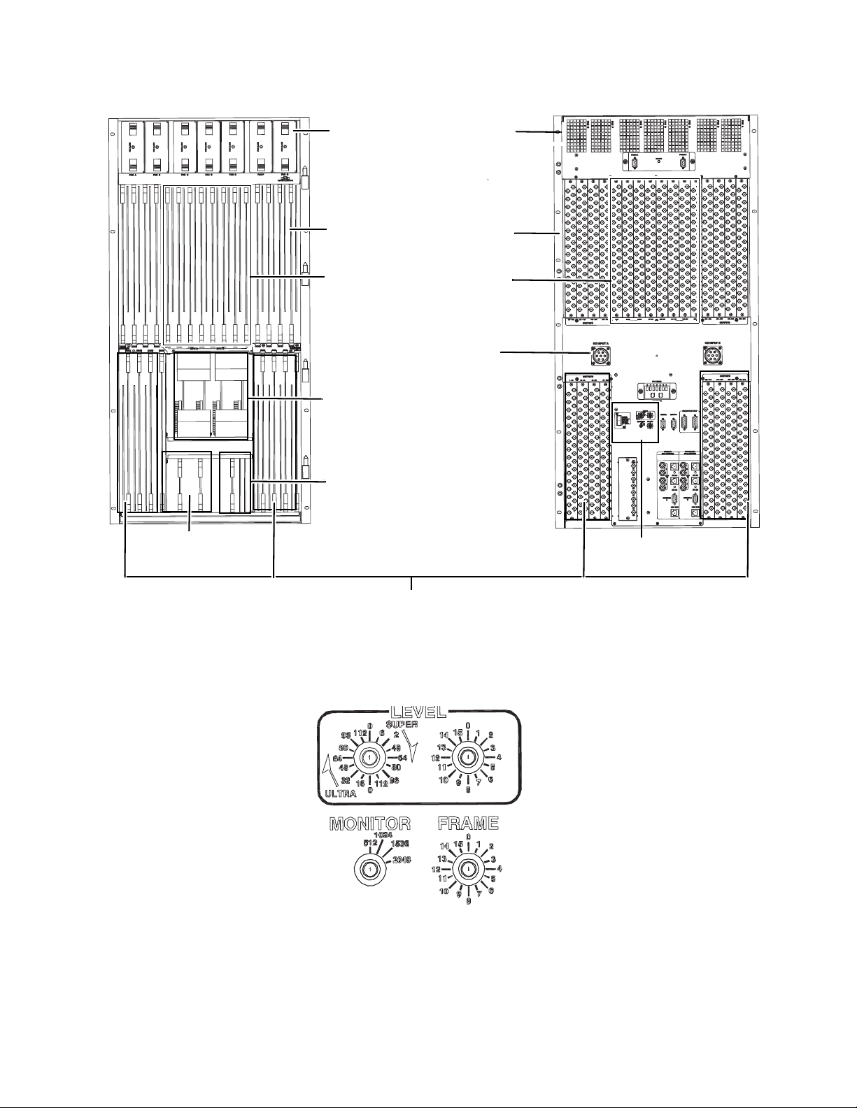
Figure 14. TRX-NXT-256x512 Asymmetric Frame, Front and Back
071827609_256X512-Frame_Front-view
071827609_256X512-Fra
me_Back-view
Broadlinx boards
Fan modules and Exhaust
vents
See Figure 15
for detail
DC Power inputs
Input and Output
boards
The outer four slots are
Output boards
The inner eight slots are
Input boards
Matrix boards
SR module
Output boards
071827612_LEVEL_MONITOR_256x512
Trinix Frames
Figure 15. The Level, Monitor, and Frame Switch For the 256x512 Routing Switcher
Trinix NXT — Installation and Service Manual 51
Page 52

Section 2 — Planning Guide
Fan modules
DC Power inputs
Matrix and Secondary Broadlinx
boards
Fan modules
Output Boards
Input Boards
Output Boards
DC Power inputs
Matrix and Primary
Broadlinx boards
See Figure 17 on
page 53 for detail
Figure 16. TRX-NXT-512x1024 Asymmetric Frame, Front and Back
52 Trinix NXT — Installation and Service Manual
Page 53

Trinix Frames
Figure 17. The Level, Monitor, and Frame Switch For the 512x1024 Routing Switcher
Trinix NXT — Installation and Service Manual 53
Page 54

Section 2 — Planning Guide
Figure 18. Protected Paths, Signal Flow, and Power Supply System for TRX-NXT-512x512 Router.
54 Trinix NXT — Installation and Service Manual
Page 55

Power Supplies
The symmetrical Trinix routing family uses an internal power supply. The
128 and 256 frames can use two power supplies. The optional (and recom
mended) second power supply provides redundancy and increased reliability due to load sharing; both supplies work less, creating less strain and
decreasing the likelihood of failure of either unit.
All power supplies are front loading, can be hot-swapped, and has its own
fan for cooling. The supply uses automatic line sensing technology to adapt
the supply to all major power standards throughout the world.
Note Grass Valley strongly recommends, whenever possible, using the AC high
In AC power applications, the 512x512 frames are equipped with two
power supplies mounted in a separate frame. Space for two additional sup
plies for redundancy is provided. Redundant power supplies are highly
recommended for On-Air or Business-critical routers. The 512x512 router’s
power supply frame may be mounted above or below the router’s main
frame, depending on video cable routing requirements (or weight distribu
tion requirements).
Trinix Frames
-
line to reduce line currents and heat within the power supplies.
-
-
The back panel of the frame provides a separate AC connector for each
power supply. Each power supply has its own separate IEC AC power
cord. Each power cord should be plugged into a separate dedicated (20A
AC low line, 10A AC high line) power circuit. This action prevents the
router from having one failed supply being able to trip the breaker on a
heavily loaded circuit, and then temporarily shutting off other functioning
power supplies or equipment. The back panel of the frame also provides an
optional 48VDC input connector. The 48VDC input connector is an option
for additional power redundancy. DC power can be supplied by an
external “Tertiary” supply (a Trinix option), or by a customer provided
48VDC power source. (See
requirements.)
CAUTION External 48 VDC Inputs are not fused. Customers must ensure that the 48
VDC power sources, which they must provide, are properly fused.
Each power supplies deliver 48 volts to all components and the individual
components convert down the voltages for their particular need.
It is possible to operate the router with a combination of internal power
supplies and an external DC power source for additional redundancy.
DC Power Input section for the Trinix power
Asymmetrical Router
Note For information about optional Power Supply configurations for the Asym-
metrical routers, see Trinix Asymmetrical Power Supply Configurations on
page 227.
Trinix NXT — Installation and Service Manual 55
Page 56

Section 2 — Planning Guide
The Asymmetrical Trinix router provides two isolated DC input power
connectors only. An external AC to DC power supply provides power for
these connectors or a customer may provide a 48 VDC power source.
CAUTION External 48 VDC Inputs are not fused. Customers must ensure that the 48
VDC power sources, which they must provide, are properly fused.
An external power supply rack is available that will accommodate up to
four redundant, load sharing power supply modules for each power con
nector on the frame. The 128x256 and 256x512 frames each have two power
connectors. The back panel of the power supply rack provides a separate
AC connector for each power supply. Each power supply cord should be
plugged into a separate dedicated (20A AC low line and 10A AC high line)
power circuit.
Note Grass Valley strongly recommends, whenever possible, using the AC high
line to reduce line currents and heat within the power supplies.
The Trinix 512x1024 frames have a minimum of two PS trays with four
power modules in each tray. Every power supply module that is used in an
Asymmetrical frame has its own separate IEC AC power cord. The Primary
power supply trays connect to the frame in the rear of the chassis on the A1
and A2 correctors. Secondary power supplies may be added to the B1 and
B2 connectors using an additional pair of power supply trays (See
Asymmetrical Power Supply Configurations on page 227, for more information).
Trinix
-
(See the DC Power Input section of the Electrical Specifications, for the Asymmetrical Trinix power requirements.)
Cooling System
The Trinix router uses fan modules (FM-33000) for cooling the main
chamber of the frame. A fan module consists of two blower-type fans that
are housed in a mechanical assembly. The 128 x 128 frame uses two mod
ules, the 256 x 256 frame uses three, and the 512 uses six. The 128x256 frame
uses three fan modules, and the 256x512 frame uses seven fan modules. The
fan modules are front-loading and can be hot-swapped.
Note The door on the front of all Trinix frames should be closed when the router is
Airflow openings for the 128 frame are shown in Figure 19. Air is taken in
from the sides of the frame (primarily the left side), where the air is drawn
across the Input and Output boards, past the matrix board, and up to the
top rear of the frame where it is expelled from the router. A small amount
of air is drawn from the right side of the frame as well to help cool the
matrix boards. A Front-Air Vent is provided as an additional router-cooling
option. This option is described on page
-
in use.
429.
56 Trinix NXT — Installation and Service Manual
Page 57

Trinix Frames
Right side Rear Left side
IN
IN
IN
OUT OUT
Right side
Rear
Left side
IN
IN
IN
OUT
ININ
IN
Figure 19. Airflow Openings for TRX-NXT-128x128 Frame.
Airflow openings for the 256 and 512 frames are shown in Figure 20 and
Figure 21. Air is taken in from the bottom of the frame (cut-outs are located
on the very bottom of the sides), and from the central area of the left and
right sides. The air is drawn to the top rear of the frame, across all of the
Input and Output boards as well as the Matrix boards, and then expelled
out the back of the router.
Figure 20. Airflow Openings for TRX-NXT-256x256 Frame.
Trinix NXT — Installation and Service Manual 57
Page 58

Section 2 — Planning Guide
Right side Rear Left side
OUT
IN
IN
IN IN
IN IN
IN
IN
OUT
Figure 21. Airflow Openings for TRX-NXT-512x512 Power Supply and Main Frame.
Using a set of central fan modules to cool the main chamber eliminates the
possibility of cooling loss in one area due to failure of a single fan.The
system will continue to operate if a fan does fail. Grass Valley recommends
that you replace the fan and return the system to normal redundant opera
tion as soon as possible.
Cooling Asymmetric Frames
Air is taken in from the bottom of the frame (cut-outs are located on the
very bottom of the sides). This air is then drawn up through all of the Input
and Output boards as well as the matrix boards to the top rear of the frame.
The air is then expelled out the back of the router. The airflow openings for
the 128x256 frame are shown in
Figure 22 on page 59. The airflow openings
for the 256x512 frame are shown in Figure 23.
The 512x1024 frame is the result of years of researching how to cool a
routing switcher. The routing switcher has two fans, one on the top and one
on the bottom. Air is drawn in from the bottom of the fans and is exhausted
through the top of the frame. A two (2) RU space should be kept free on the
bottom of the frame and fan to ensure enough airflow. Do NOT place any
thing on the top of the 512x1024 frame to prevent over heating.
A two (2) RU vent option is also available to draw intake air in from the
front of the frame (
Figure 24 on page 60).
-
-
58 Trinix NXT — Installation and Service Manual
Page 59

Figure 22. Airflow Openings for the TRX-NXT-128x256 Main Frame
IN
OUT
071827609_128x256-Cooling
Figure 23. Airflow Openings for the TRX-NXT-256x512 Main Frame.
Side
Rear
Trinix Frames
OUT
071827609_256X512-Frame_Coo
ling
IN
A two (2) RU space should be kept free on the bottom of the frame and fan
to ensure enough airflow to prevent the routing switcher from overheating.
Trinix NXT — Installation and Service Manual 59
Page 60

Section 2 — Planning Guide
071827612-512x1024-w-fans_r1.ai
OUT
IN
071827612-512x1024-w-fans_r1.ai
2 RU Air Vent
located at the
bottom of the frame
1 RU Fans located at
the top and bottom
of the frame
A two (2) RU vent option is also available to draw intake air in from the
front of the frame.
Figure 24. TRX-NXT-512x1024
60 Trinix NXT — Installation and Service Manual
Page 61

Trinix Frames
Sync Reference Options
For synchronous vertical interval switching the same sync reference signal
must be sent to the control system (for example, Jupiter CM-4000 or CM-
4400) and to the Trinix. (The Trinix will operate without a sync connection
but switching will be non-synchronous.) Each sync input uses looping 75ohm BNC connectors.
The sync signal can be NTSC or PAL black burst, or tri-level (HD) sync, and
up to four sync signals can be mixed within the same frame on an outputboard basis. For example, NTSC sync could be used for one set of 32
outputs and HD sync for another set of 32 outputs.
In the TRX-NXT-128x128, TRX-NXT-256x256, and theTRX-NXT-512x1024
Routing switchers, one or two independent sync signals can be connected
to a NR-33000 Broadlinx board and either of these can then be selected for
use on each output board. Adding a second Broadlinx board provides four
independent sync sources.
In TRX-NXT-512x512 Routing switchers, which are normally supplied
with an SR-33500 Sync/OPM board, up to four independent sync sources
can be connected and any of the four can be selected for each output board.
If desired, an NR-33000 board can be installed in the associated power
supply frame to provide Broadlinx capability. It is also possible to divide
the sync sources between the SR-33500 and the Broadlinx board but the
maximum number of sync sources is always four.
In TRX-NXT-256x512 Routing switchers, which are normally supplied
with a TRX-SR Sync/OPM board, up to four independent sync sources can
be connected and any of the four can be selected for each output board. It
is also possible to divide the sync sources between the TRX-SR and the
Broadlinx board but the maximum number of sync sources is always four.
In the TRX-NXT-128x256 and TRX-NXT-512x1024 Routing switchers, the
TRX-OPM board does not process sync references. Sync is supplied exclu
sively from the NR-33000 boards.
Sync Redundant mode
For all Trinix routers Two Broadlinx boards can be operated in the Sync
Redundant mode. That is, the sync signals are looped through each board.
If the primary Broadlinx board fails, the system will switch automatically
to the secondary board. The number of sync signals is limited to two for
redundant operation.
For Sync reference details, see Sync Reference Connections on page 157.
Output Monitoring
The TRX-NXT-128x128, and the TRX-NXT-256x256 frames, uses two pairs
of output monitor ports, which are provided by the NR-33000 board (one
side of each pair is inverted). Two additional dual ports are optionally
Trinix NXT — Installation and Service Manual 61
-
Page 62

Section 2 — Planning Guide
available when a second NR-33000 is added; this would provide four
monitor ports.
• The SR-33500 Sync/OPM board, on the TRX-NXT-512x512 frames, provides four monitoring ports.
• The TRX-SR Sync/OPM board, on the TRX-NXT-256x512 frames, provides four monitoring ports.
• The TRX-OPM board, on the TRX-NXT-128x256 and TRX-NXT512x1024 frames, provides four monitoring ports.
Symmetric Frames
For configurations that require multiple frames, the monitor signals are
brought through a Port expander used as a combiner (see
Expanded Systems).
Monitoring with
Asymmetric Frames
The TRX-SR Sync/OPM and TRX-OPM boards provide four monitor
inputs to accommodate cascading multiple frames into a single output
monitor stream. These boards are specific to the asymmetrical routers, for
more information see
section.
Asymmetrical Frames on page 200 in the Monitoring
3Gp/s Output Monitoring
The TRX-GPMEZ-3G mezzanine module on the TRX-HO-3G base Output
Module in the Trinix Symmetrical frame, receives a stream that is
1080p59.95, it is the down-converted to 1080i59.95.
The TRX-SR Sync/OPM and TRX-OPM boards support 3Gp/s Output
Monitoring in the asymmetrical frames.
Signal Flow
Trinix is a three-board routing system, where the input board, output
board, and matrix board are the basic modules.
The signal flow through a 128 x 128 routing system is shown in Figure 25
on page 63 as an example. Inputs are received and outputs are delivered to
the rear of the frame directly with a connection to the rear panels (no
cabling).
62 Trinix NXT — Installation and Service Manual
Page 63

Trinix Frames
32 Output
Card
Matrix Card
(128 x 128)
32 Output
Card
32 Output
Card
32 Output
Card
32 Input
Card
32 Input
Card
32 Input
Card
32 Input
Card
Figure 25. Input and Output Routing Through Matrix Board For 128 x 128 Routing Switcher.
Trinix NXT — Installation and Service Manual 63
Page 64

Section 2 — Planning Guide
JO_75
Outputs 480-511
B
Figure 26. Signal Flow for the 512x1024 Routing Switcher - Top
JO_74
JO_73
JO_72
Outputs 384-415
Outputs 416-447
Outputs 448-479
127
3
96
95
2
64
63
1
32
31
0
384-415 480-511416-447 448-479
0
127
3
384-415
96
95
2
64
63
1
32
31
0
480-511 416-447448-479
0
127
3
96
95
2
64
63
1
32
31
0
0
127
3
96
95
2
64
63
1
32
31
0
0
JO_71
JO_70
JO_69
JO_68
Outputs 352-383
Outputs 320-351
B
287-256 319-288 351-320 383-352
256-287288-319320-351352-383
A
127
3
415-384511-480 447-416479-448
96
95
2
64
63
1
32
31
0
0
127
3
128-159224-255 160-191192-223
96
95
2
64
63
1
32
31
0
0
Outputs 288-319
96
64
OUTPUTS
32
0
96
64
INPUTS
32
0
Outputs 256-287
127
3
95
2
63
1
31
0
127
3
95
2
63
1
31
0
JO_67
Outputs 224-255
(0x37)
(0x36)
A
B
256-287288-319320-351352-383
0-3132-6364-9596-127
96
64
OUTPUTS
32
0
96
64
INPUTS
32
0
3
2
1
0
3
2
1
0
127
95
63
31
127
95
63
31
JO_66
Outputs 192-223
224-255128-159 160-191 192-223
384-415 480-511416-447 448-479
JO_65
Outputs 160-191
96
64
32
0
96
64
32
0
(0x34)(0x35)
3
2
1
0
3
2
1
0
JO_64
Outputs 128-159
127
127-9631-0 63-32 95-64
95
63
31
127
95
63
31
256-287 288-319 320-351 352-383
JO_63
JO_62
JO_61
JO_60
Outputs 96-127
B
A
3
96
2
64
1
32
0
0
3
96
2
64
1
32
0
0
Outputs 32-63
Outputs 64-95
127
95
63
31
255-224 159-128191-160223-192
127
95
63
160-191 192-223
31
128-159 224-255
(0x30)
3
96
2
64
1
32
0
0
3
96
2
64
INPUTS OUTPUTS
1
32
0
0
10h13h 12h 11h14h17h 16h 15h18h1B 1A 19h1F 1E 1D 1C
Outputs 0-31
127
95
63
31
96-127 0-3132-6364-95
127
95
63
31
0-31 32-63 64-95 96-127
Physical
(Logical)(0x31)(0x32)(0x33)
A
B
12
CONTROL INPUTS OUTPUTS
Inputs 480-511
JI_15
JMx_47
(mez)
Inputs 448-479
JI_14
16
CONTROL INPUTS OUTPUTS
Inputs 416-447
JI_13
JMx_46
(base)
Inputs 384-415
JI_12
B
11
CONTROL INPUTS OUTPUTS
Inputs 352-383
JI_11
JMx_45
(mez)
A
Inputs 320-351
JI_10
15
JMx_44
CONTROL
(base)
B
Inputs 256-287
Inputs 288-319
JI_09
JI_08
CONTROL
Inputs 224-255
(0x27)
13
JI_07
(mez)
A
(0x26)
17
CONTROL INPUTS OUTPUTS
B
Inputs 160-191
JMx_42
(base)
Inputs 128-159
JMx_43
Inputs 192-223
(0x24)(0x25)
JI_06
JI_05
JI_04
10
CONTROL INPUTS OUTPUTS
A
Inputs 96-127
JI_03
JMx_41
(mez)
Inputs 64-95
JI_02
14
CONTROL
Inputs 32-63
(0x20)
JI_01
JMx_40
(base)
Inputs 0-31
0003 02 010407 06 05080B 0A 090F 0E 0D 0C
JI_00
A
Physical
(Logical)(0x21)(0x22)(0x23)
64 Trinix NXT — Installation and Service Manual
071827612_Trinix 512x1024 top Layout.
Page 65

Figure 27. Signal Flow for the 512x1024 Routing Switcher - Bottom
JII_35
JII_34
JII_33
JII_32
JII_31
JII_30
JII_29
JII_28
JII_27
JII_26
JII_25
JII_24
JII_23
Trinix Frames
JII_22
JII_21
JII_20
Inputs 480-511
JMx_57
480-511
448-479
416-447
384-415
896-927 992-1023928-959 960- 991
Inputs 448-479
(base)
12
0
0
31
32
1
63
64
2
95
96
3
127
0
0
31
32
1
63
64
2
95
96
3
127
Inputs 416-447
CONTROL
INPUTS
OUTPUTS
(mez)
JMx_56
352-383
31
63
95
256-287288-319320-351
127
768-799 800- 831 832-863 864-895
31
63
95
127
Inputs 224-255
(0x27)
(base)
JMx_53
384-415 480-511416-447 448-479
31
63
95
127
31
63
95
736-767640-671 672-735 704-735
127
(0x26)
0
1
2
3
0
1
2
3
A
13
Inputs 192-223
0
32
64
96
0
32
64
96
CONTROL INPUTS
OUTPUTS
Inputs 352-383
(base)
JMx_55
31
63
95
128-159224-255 160-191192-223
127
31
63
95
896-927992-1023 928-959960-991
127
Inputs 320-351
B
CONTROL
11
0
0
32
1
INPUTS
64
2
96
3
0
0
32
1
OUTPUTS
64
2
96
3
Inputs 384-415
BB
CONTROL
16
0
0
32
1
INPUTS
64
2
96
3
0
0
32
1
OUTPUTS
64
2
96
3
Inputs 256-287
Inputs 288-319
A
CONTROL INPUTS OUTPUTS
(mez)
JMx_54
15
0
0
31
32
1
63
64
32-6364-9596-127
2
95
96
0-31
3
127
0
0
31
32
832-863864-895
1
63
64
2
95
96
768-799800-831
3
127
Inputs 128-159
Inputs 160-191
(0x24)(0x25)
B
(mez)
JMx_52
256-287
0
31
288-319 320- 351 352-383
1
63
2
95
3
127
0
31
1
63
2
95
608-639512-543 544-575 576-607
3
127
17
0
32
64
96
0
32
64
96
CONTROL INPUTS
OUTPUTS
Inputs 96-127
A
JMx_51
128-159 224-255160-191 192-223
31
63
95
127
736-767 640-671672-735704-735
31
63
95
127
Inputs 64-95
(base)
10
0
0
32
1
64
2
96
3
0
0
32
1
64
2
96
3
CONTROL
INPUTS
OUTPUTS
Inputs 32-63
(0x20)
JMx_50
0-31
32-63 64-95 96-127
608-639 512-543544-575576-607
Inputs 0-31
0003 02 010407 06 05080B 0A 090F 0E 0D 0C
A
(mez)
0
31
1
63
2
95
3
127
0
31
1
63
2
95
3
127
14
0
32
64
96
0
32
64
96
Physical
(Logical)(0x21)(0x22)(0x23)
CONTROL
INPUTS
OUTPUTS
B
Outputs 992-1023
JO_95
B
A
Outputs 896-927
Outputs 928-959
Outputs 960-991
JO_94
JO_93
JO_92
Outputs 864-895
JO_91
A
Outputs 832-863
Outputs 800-831
JO_90
JO_89
B
(0x37)
(0x36)
Outputs 768-799
JO_88
Outputs 736-767
JO_87
Outputs 704-735
JO_86
Outputs 672-703
JO_85
A
B
A
Physical
Outputs 544-575
JO_81
(0x30) (Logical)(0x31)(0x32)(0x33)
1013 12 111417 16 15181B 1A 191F 1E 1D 1C
Outputs 512-543
JO_80
071827612_Trinix 512x1024 Bottom Layout.
(0x34)(0x35)
Outputs 576-607
Outputs 640-671
JO_84
Outputs 608-639
JO_83
JO_82
Trinix NXT — Installation and Service Manual 65
Page 66

Section 2 — Planning Guide
• Save/recall settings
• Mono mode
• Setup on/off
• Chroma kill
•Comb/trap filter
•AGC on/off
• Manual gain control
• ACC on/off
• Manual chroma
control
•Blank video (per
VBI line)
• Add setup (per VBI
line)
• Reserve VBI line for
data
• Horizontal timing
• Detail enhancement
• Display channel
status
• Insert Error Detection and Handling
(EDH) data
• Contrast / Y gain
• Saturation /
chroma gain
•Brightness / Y
offset
•Hue / chroma
phase
• Notch decode on/
off (VBI)
• Chroma kill (VBI)
Analog Processing Control
For a description of the various Input, Output, and Matrix boards available
for Trinix, contact your Grass Valley account representative.
The VI-33100 universal input module accepts analog as well as digital signals. Adjustments for analog sign
als include the following:
For more information about the VI-33100 module, please refer to Chapter
6: Analog Input Processing on pa
ge 379.
Pre-wiring
All Trinix Routing switchers are pre-wired to the size of the frame. For
example, a 128-frame is pre-wired to 128 x 128 with all rear panels and
BNCs in place; the 256-frame is pre-wired to 256 x 256.
By convention, Routing switcher
M x N (P x Q)
Connector Numbering
66 Trinix NXT — Installation and Service Manual
This indicates that the functional router
x Q). Symmetrical Trinix pre-wiring is only possible in multiples of 128 x
128, as that is the smallest frame size increment.
Late-model Trinix routers have video input/output connectors that begin
with “1” instead of “0.” An adhesive overlay set, which indicates connector
groups using a 0-based numbering scheme (for example, Inputs “0-31,”
Inputs “32-63,” etc.) is provided for customers who are using a 0-based
control system such as Jupiter.
sizes are shown as:
size is M x N and is pre-wired to (P
Page 67

Alarm System
EXTERNAL CIRCUIT
(EXAMPLE)
NOT TO EXCEED
24 VDC @ 20 mA
REAR PANEL BNC
The operation of cooling fans, frame power supplies, on-board power supplies, and primary vs. secondary Broadlinx boards are all monitored. Any
alarm for these critical items is treated as a Primary alarm. With the release
of Broadlinx 3.1, the router’s system alarm has two modes, “No alarms”
and “Primary alarm.” All alarms (multiple fan failure, power supply
failure, etc.) are considered Primary alarms. All major components include
a local alarm LED.
The master alarm indicator is on the front panel (Power/Alarm) where
green indicates normal operation and red indicates a Primary alarm.
Symmetrical Frame
The rear panel Alarm BNC is configured to report primary alarms only. The
TRX-NXT-128x128 and TRX-NXT-256x256 is configured via jumper on the
NR/SR-33000 board. The location of the board is shown in
page 136 and Figure 65 on page 138. The TRX-NXT-512x512 is configured
via a jumper on the RP-33500 512 x 512 Rear Panel board as shown on
Figure 68 on page 141.
Trinix Frames
Figure 63 on
The Alarm BNC for the TRX-NXT-256x512 version is configured the same
as the TRX-NXT-128x128 or TRX-NXT-256x256. In other words, through
the jumper on the NR-33000 board. See
Note Secondary alarms are no longer supported.
Figure 28.
Fan and Power Supply alarm status is concentrated on the SC board and is
reported through the OPM board for the Asymmetrical frames. The Power
Supply alarms are configured with the dual in-line package (DIP) switches
on the SC boards. (See
Figure 28. Rear Panel Master Alarm Circuit (left) and Example Of Customer-supplied Indicator
Circuit (right).
Configuration DIP Switches on page 231)
Trinix NXT — Installation and Service Manual 67
Page 68

Section 2 — Planning Guide
All of the alarm and status information is gathered by the Broadlinx technology to make it available to the user via Web pages. For more information, see Section 6-Broadlinx Software on page 285.
68 Trinix NXT — Installation and Service Manual
Page 69

Duplication and Expansion
Trinix
256x256
0 -255
0 - 255
0 -255
Dual outputs
16
PE 33016
used as
splitters
Trinix router’s inputs and outputs are designed to duplicated or expanded
using passive splitter/combiner expansion panels. Unused connectors
should be terminated for optimum performance.
Note For Jupiter-controlled (0-based) systems, the input/output numbers in the
Frame numbers are determined by the input/output blocks served by the
particular frame. For example, for a TRX-NXT-256x256 router, inputs 1-256
and outputs 1-256 must be connected to frame zero. For more information
about frame numbering, see
Output Duplication - Dual
The PE-33016 and PE2X2-3G Port expanders are passive, transformerbased modules that can be used to provide two copies of the same signal.
The PE-33016 should be used for SD and HD signals. The PE2x2-3G pro
vides the necessary bandwidth for 3Gp/s operations. The PE2x2-3G can
also be used for SD and HD operation. Functionality of the expander is bidirectional and depends on connections only; no configuration is required.
Figure 29 and Figure 30 show a splitting application. In the figures below,
the PE33016 Port expander is used for an example only. Use the PE33016
Port expander for HD operations and the PE2x2-3G Port expander for
3Gp/s operations. Unused connectors should be terminated for optimum
performance.
Duplication and Expansion
following discussion should be decreased by one (1). For example, block 1256 should be understood as block 0-255, etc.
Frame Number Settings on page 212.
-
Figure 29.
Trinix NXT — Installation and Service Manual 69
Page 70

Section 2 — Planning Guide
1B
1A
1B
1A
Exterior sideInterior side
(Terminated)
Figure 30. PE-33016 Used to Provide 16 Dual Outputs.
In the splitting application, a port expander can be used to provide dual
outputs in groups of 16 outputs. Use the PE33016 Port expander for HD
operations and the PE2x2-3G Port expander for 3Gp/s operations. All
outputs are non-inverting. For example, a 256 x 256 router could be
arranged as follows:
• 256 inputs x 240 single outputs and 16 dual outputs - uses 1 Port
expander, or
• 256 inputs x 224 single outputs and 32 dual outputs - uses 2 Port
expander, or
• 256 inputs x 208 single outputs and 48 dual outputs - uses 3 Port
expander... etc.
Figure 31 shows a router with 240 single outputs and 16 dual outputs. In
the figure below, the PE33016 Port expander is used as an example.
1 - 16
1
PE 33016
used as
splitter
1 - 16
Dual outputs
17 - 256
Single outputs
Figure 31. 240 Single Outputs and 16 Dual Outputs Example
Frame 0
1 - 256
Trinix
256 x 256
70 Trinix NXT — Installation and Service Manual
Page 71

Duplication and Expansion
In this application, 16 of the PE-33016 or PE2x2-3G rear BNCs can be used
for inputs (outputs from the router) and all 32 of the front BNCs can be used
for outputs.
The MK-33000 Mounting kit can have a maximum of 16 PE-33016 or PE2x23G modules mounted. The mounting kit is eight rack units high and is
approximately four inches deep.
router with a single port expander mounted in an MK-33000. The port
expander can be either the PE33016 or the PE2x2-3G Port expanders. Using
a single port expander provides 112 single outputs and 16 dual outputs.
Figure 33 on page 73 shows a 256 input router with 256 dual outputs; this
arrangement requires 16 PE-33016 Port expanders.
1
Figure 32 on page 72 shows a 128 input
1.
All unused connectors must be terminated. 16 terminators are supplied with each PE-33016.
Trinix NXT — Installation and Service Manual 71
Page 72

Section 2 — Planning Guide
Dual outputs
123 16
1A
These 16
cables connect
to rear of PE
1B
2A
2B
3A
3B
16A
16B
Terminate
Unused BNCs
PE-33016-1
Exterior
390-1796-00
PE-33016-1
Interior
390-1797-00
Figure 32. Use of Single PE-33016 to Provide Dual Outputs for 16 Switcher Outputs
72 Trinix NXT — Installation and Service Manual
Page 73

Duplication and Expansion
A
B
C
16 PE-30016 Expander
Modules in MK-33000
Mounting Kit
EXTERIOR
INTERIOR
3.25 in.
(82 mm)
Figure 33. PE-33016 Port Expanders Provides 256 Dual outputs for 256 Input Switcher.
Trinix NXT — Installation and Service Manual 73
Page 74

Section 2 — Planning Guide
Output Duplication - Quad
The PE-33008 Port expander can provide quad outputs in groups of 16
outputs for SD or HD options. The PE-33008 Port expander functions for
data rates from 270Mb to 1.5 Gb. All outputs are non-inverting. A 128 x 128
Routing switcher could be arranged in the following manner:
• 128 inputs x 112 single outputs and 16 quad outputs - uses 2 port
expanders
or
• 128 inputs x 96 single outputs and 32 quad outputs - uses 4 port
expanders
or
• 128 inputs x 80 single outputs and 48 dual outputs - uses 6 port
expander... etc.
In this application, the eight (8) PE-33008 rear BNCs are used for inputs
(outputs from the router) and all 32 of the front BNCs are used for outputs.
Up to 16 PE-33008 modules can be mounted in an MK-33000 Mounting Kit,
which is 8 RU high and approximately 4 inches (100 mm) deep.
Figure 34 shows a 128 input router with two PE-33008s mounted in an MK-
33000; this provides 112 single outputs and 16 quad outputs. A 256 input
router with 128 single outputs and 128 quad outputs would appear similar
1
1.
All unused connectors must be terminated with 75-ohm terminators; for PE-33008 applications terminators must be supplied
by end-user.
74 Trinix NXT — Installation and Service Manual
Page 75

Duplication and Expansion
Quad outputs
123 8
1A
2A
These cables
connect to
rear of PE
Connections
to 2nd
PE-33008
are similar
1B
1C
1D
2B
2C
2D
3A
3B
3C
3D
8A
8B
8C
8D
Terminate
Unused BNCs
Terminate
Unused BNCs
PE-33008-1
Exterior
390-1795-00
PE-33008-1
Interior
390-1794-00
Figure 34. Use of 2
PE 33008s to Provide
Quad Outputs for 16
Switcher Outputs
to the system shown in Figure 33; this arrangement would require 16 PE33008 Port expanders.
Trinix NXT — Installation and Service Manual 75
Page 76

Section 2 — Planning Guide
1A
1B
Exterior sideInterior side
1A
1B
Expanded Systems
The PE-33016, PE-2X2 3G, and PE-33008 Port expanders can be used to
combine outputs (SD and HD options) for an input expansion application.
The PE-2X2 3G is required for 2X2 expansion in 3G systems, but will also
work for SD and HD systems. The PE-33016 and PE-33008 will not work
with 3G systems. In
Figure 35 and Figure 36, a PE-33016 or PE-2X2 3G is
downstream of the router. The router will present only one of the two possible signals to each combiner, which will then produce two copies of that
signal. Only one of the input signals will be present at a time and this signal
is then duplicated. Any unused connectors should be terminated for
optimum performance.
The port expanders are mounted in an MK-33000 Mounting Kit as
described previously (
Figure 35. PE-33016 Used as a Combiner.
Figure 33 on page 73).
76 Trinix NXT — Installation and Service Manual
Page 77

Duplication and Expansion
Possible expanded configurations include:
• 1024 inputs x 512 dual outputs
• 1024 inputs x 1024 dual outputs
• 512 inputs x 1024 outputs
• 2048 inputs x 2048 outputs (SD and HD only)
• 1024 inputs x 1024 outputs
Some of these configurations are shown on the following pages. Notice that
the same port expander type is used for both downstream combining (for
input expansion) and upstream splitting (for output expansion). All
outputs are non-inverting. In the figures below the PE33016 Port expander
is used as an example. Use the PE33016 Port expander for HD operations
and the PE2x2-3G Port expander for 3Gp/s operations.
Trinix NXT — Installation and Service Manual 77
Page 78

Section 2 — Planning Guide
Trinix
512 x 512
1 - 512
1 - 512
513 - 1024
1 - 512
Trinix
512 x 512
Trinix
512 x 512
1 - 512
1 - 512
513 - 1024
1 - 512
1 - 512
Dual outputs
32
PE 33016
used as
combiners
Trinix
512 x 512
Inputs expanded
to 1024
Outputs
expanded
to 1024
32
PE 33016
used as
splitters
512 - 1024
Frame 0
Trinix
512 x 512
17 - 512
1 - 512
513 - 1024
17 - 512
Dual outputs
32
PE 33016
used as
combiners
Inputs expanded
to 1024 (restricted)
1 - 512
Trinix
512 x 512
Frame 1
1 - 16
Trinix
512 x 512
17 - 512
1 - 16
1 - 512
513 - 1024
17 - 512
17 - 512
Outputs
expanded
to 1024
(restricted)
32
PE 33016
used as
splitters
Frame 0
Frame 1
Frame 0
Frame 2
Frame 0
Trinix
512 x 512
Frame 2
Figure 36. Examples of Input and Output Expansion.
78 Trinix NXT — Installation and Service Manual
The term “restricted” refers to a wiring scheme where some signal paths are
not available. For example, the second system shown in the above figure
will not allow outputs 1-16 to receive inputs 513-1024.
Page 79

Duplication and Expansion
Figure 37. 1024 x 1024 Systems.
Frame 0
1 - 512
Trinix
512 x 512
1 - 512 Dual outputs
32
PE-33016
used as
splitters
Frame 2
1 - 512
Trinix
512 x 512
1 - 512
513 - 1024
32
PE-33016
used as
combiners
1 - 512
Inputs and outputs
expanded to 1024
513 - 1024
32
PE-33016
used as
splitters
513 - 1024
513 - 1024
Frame 1
Trinix
512 x 512
Frame 3
Trinix
512 x 512
1 - 512
513 - 1024
32
PE-33016
used as
combiners
513 - 1024
Dual outputs
Trinix NXT — Installation and Service Manual 79
Page 80

Section 2 — Planning Guide
513 - 1024
Inputs expanded to 1024
Outputs expanded to 2048
1 - 512
1 - 512
1 - 512
1 - 512
513 - 1024
513 - 1024
1 - 512
1 - 512
Inputs
Inputs
Dual outputs
Trinix
512 x 512
Tri n ix
512 x 512
Trinix
512 x 512
Trinix
512 x 512
64
PE-33008
used as
1 x 4
splitters
64
PE-33008
used as
1 x 4
splitters
32
PE-33016
used as
combiners
Dual outputs
32
PE-33016
used as
combiners
Frame 0
Frame 2
Frame 8
Frame 10
1537 - 2048
1025 - 1536
Dual outputs
Trinix
512 x 512
Tri n ix
512 x 512
Trinix
512 x 512
Trinix
512 x 512
32
PE-33016
used as
combiners
Dual outputs
32
PE-33016
used as
combiners
Frame 1
Frame 3
Frame 9
Frame 11
513 - 1024
513 - 1024
513 - 1024
Figure 38. 1024 x 2048 Systems
80 Trinix NXT — Installation and Service Manual
Page 81

Inputs expanded to 2048
Outputs expanded to 1024
1 - 512
1 - 512
513 - 1024
513 - 1024
1 - 512
1 - 512
Dual outputs
Inputs
Trinix
512 x 512
Trinix
512 x 512
Trinix
512 x 512
Trinix
512 x 512
64
PE-33008
used as
4 x 1
combiners
32
PE-33016
used as
splitters
513 - 1024
Inputs
32
PE-33016
used as
splitters
Frame 0
Frame 2
Frame 1
Frame 3
1025 - 1536
513 - 1024
Dual outputs
Inputs
Trinix
512 x 512
Trinix
512 x 512
Trinix
512 x 512
Trinix
512 x 512
64
PE-33008
used as
4 x 1
combiners
32
PE-33016
used as
splitters
1537 - 2048
Inputs
32
PE-33016
used as
splitters
Frame 4
Frame 6
Frame 5
Frame 7
1025 - 1536
1025 - 1536
1537 - 2048
1537 - 2048
Figure 39. 2048 x 1024 System
Duplication and Expansion
Trinix NXT — Installation and Service Manual 81
Page 82

Section 2 — Planning Guide
1 - 512
1 - 512
1 - 512
Inputs
Trinix
512 x 512
64
PE-33008
used as
1 x 4
splitters
Frame 0
Trinix
512 x 512
Frame 2
1 - 512
1 - 512
Trinix
512 x 512
Frame 8
Trinix
512 x 512
Frame 10
1025 - 1536
Inputs
Trinix
512 x 512
64
PE-33008
used as
1 x 4
splitters
Frame 4
Trinix
512 x 512
Frame 6
Trinix
512 x 512
Frame 12
Trinix
512 x 512
Frame 14
1 - 512
Dual outputs
64
PE-33008
used as
4 x 1
combiners
513 - 1024
Dual outputs
64
PE-33008
used as
4 x 1
combiners
1025 - 1536
Dual outputs
64
PE-33008
used as
4 x 1
combiners
1537 - 2048
Dual outputs
64
PE-33008
used as
4 x 1
combiners
513 - 1024
Inputs
Tri n ix
512 x 512
64
PE-33008
used as
1 x 4
splitters
Frame 1
Tri n ix
512 x 512
Frame 3
Tri n ix
512 x 512
Frame 9
Tri n ix
512 x 512
Frame 11
1537 - 2048
Inputs
Trinix
512 x 512
64
PE-33008
used as
1 x 4
splitters
Frame 5
Trinix
512 x 512
Frame 7
Trinix
512 x 512
Frame 13
Trinix
512 x 512
Frame 15
Inputs and outputs expanded to 2048
513 - 1024
513 - 1024
513 - 1024
513 - 1024
1025 - 1536
1025 - 1536
1025 - 1536
1025 - 1536
1537 - 2048
1537 - 2048
1537 - 2048
1537 - 2048
Figure 40. 2048 x 2048 System
82 Trinix NXT — Installation and Service Manual
Page 83

The 512x1024 Routing Switcher
Frame 0
Trinix
512 x1024
Frame 2
Trinix
512 x1024
64
TRX-PE-2x2-3G
used as
Combiners
1-1024
513-1024
1-512
071827612_1024x1024 System_512x1024
The 512x1024 Routing switcher can be duplicated to form the following
frames:
• 1024x1024
• 512x2048
• 1024x2048
• 2048x2048
Note The 2048x2048 frame can only process SD or HD signals do to the port
expander that must be used (TRX-PE-33008).
Examples of each of these frames can be found on the pages that follow.
The 1024x1024 Frame
This configuration can process SD,HD and 3Gb/s signals.
Duplication and Expansion
Figure 41. Example of the 1024x1024 Frame
Trinix NXT — Installation and Service Manual 83
Page 84

Section 2 — Planning Guide
The 512x2048 Frame
This configuration can process SD,HD and 3Gb/s signals.
Figure 42. Example of the 512x2048 Frame
Frame 0
1-1024
Trinix
512 x1024
32
1-512
TRX-PE-2x2-3G
used as
Splitters
Frame 8
1025-2048
071827612_512x2048 System_512x1024
Trinix
512 x1024
84 Trinix NXT — Installation and Service Manual
Page 85

Duplication and Expansion
Frame 0
Trinix
512 x1024
Frame 8
Trinix
512 x1024
1-512
32
TRX-PE-2x2-3G
used as
Splitters
Frame 1
Trinix
512 x1024
Frame 9
Trinix
512 x1024
513-1024
1025-2048
32
TRX-PE-2x2-3G
used as
Splitters
64
TRX-PE-2x2-3G
used as
Combiners
1-1024
64
TRX-PE-2x2-3G
used as
Combiners
071827612_1024x2048 System_512x1024
The 1024x2048 Frame
This configuration can process SD,HD and 3Gb/s signals.
Figure 43. Example of the 1048x2048 Frame
Trinix NXT — Installation and Service Manual 85
Page 86

Section 2 — Planning Guide
Frame 0
Trinix
512 x1024
Frame 8
Trinix
512 x1024
1-512
32
TRX-PE-2x2-3G
used as
Splitters
1-1024
128
TRX-PE-33008
used as
Combiners
1025-2048
128
TRX-PE-33008
used as
Combiners
Frame 1
Trinix
512 x1024
Frame 9
Trinix
512 x1024
513-1024
32
TRX-PE-2x2-3G
used as
Splitters
Frame 4
Trinix
512 x1024
Frame 12
Trinix
512 x1024
1025-1536
32
TRX-PE-2x2-3G
used as
Splitters
Frame 5
Trinix
512 x1024
Frame 13
Trinix
512 x1024
1537-2048
32
TRX-PE-2x2-3G
used as
Splitters
071827612_2048x2048 System_512x1024
The 2048x2048 Frame
This configuration can only process SD and HD signals.
Figure 44. Example of the 2048x2048 Frame
86 Trinix NXT — Installation and Service Manual
Page 87

Termination for Pre-wired Expansion Frames
The unused BNC connectors on the port expanders should be terminated
for best performance. However, it may be desirable to install an empty or
partially filled frame with associated cabling to simplify future expansion.
When such cabling connects to a Port expander that is carrying active sig
nals, special termination hardware is required. Since the presence of prewired cabling will not permit standard BNC terminators to be installed on
the expander, an LD-33100 Loader board must be installed in the associ
ated frame in place of an input or output board to provide correct termination.
Grass Valley recommends that you terminate all unused outputs that may
be driven with an active signal. Properly shielded 75-ohm terminators or
spare infrastructure coax cables should be used. This step will ensure EMC
compliance. Spare output BNC panels that are not populated with output
boards and spare input BNCs do not need to be terminated.
Figure 45. LD-33100 Loader Board
Duplication and Expansion
-
-
Input Expansion
For example, the figure below (Figure 46) shows a 512 x 512 system that has
been expanded to 1024 x 512:
Trinix NXT — Installation and Service Manual 87
Page 88

Section 2 — Planning Guide
Input 1B - from Frame 1 Output 1.
Input 1A - from Frame 0 Output 1
Output 1A - to downstream equipment
Output 1B - not used. Termination provided by
Termination provided by LD-33000
75-ohm BNC terminator
in upstream Trinix frame.
Figure 46. 512 x 512 System Expanded to 1024 x 512
Frame 0
1 - 512
Trinix
512 x 512
1 - 512
Future input
wiring
Frame 1
(unused)
Trinix
512 x 512
32
PE 33016
used as
combiners
Installed pre-wiring
Output slots should be terminated
using LD-33100 Loader boards
outputs
1 - 512
Frame 1 contains no input or output boards, but the wiring has already
been installed between Frame 1 and the PE-331016 Port expanders.
Now consider Output 1 of Frame 0. This signal is connected to Input 1A of
the first PE-33016 Port expander. See
Figure 47. Detail of One PE-33016
Figure 47 below.
In this example:
• Only Input 1A and Output 1A are presently functional.
• Output 1B is fitted with a 75-ohm BNC terminator, which is following
the rule that unused connectors should be terminated.
• Input 1B is pre-wired to Frame 1, so there is no place for a terminator.
In this case, termination will be provided by an LD-33100 Loader board,
which has been installed in output board slot 1-32 of Frame 0. Furthermore, in this example all 16 output slots of Frame 0 should have an LD33000 installed.
• When the system is upgraded to 1024 x 512, the LD-33000 boards will
be removed and replaced by output boards. The cabling to the port
expanders is already in place.
88 Trinix NXT — Installation and Service Manual
Page 89

Duplication and Expansion
Trinix
512 x 512
Trinix
512 x 512
1 - 512
1 - 512
1 - 512
32
PE 33016
used as
splitters
Frame 0
Frame 1
(unused)
Installed pre-wiring
Future output
wiring
Input slots should be terminated
using LD-33100 Loader boards
Input 1A - from upstream equipment
Output 1A - to Frame 0 Input 1
Input 1B - not used. Termination
provided by 75-ohm BNC terminator
Output 1B - to Frame 1 Input 1.
Termination provided by LD-33100
in Frame 1.
The concepts in this example can be applied equally to both HD and SD
systems with PE-33008 Port expanders. For example, they would apply to
a 1024 x 1024 system that is pre-wired for expansion to 2048 x 1024 (similar
to the system shown in
Figure 37 on page 79, where LD-33100 Loader
boards would be installed in place of output boards in Frames 4 through 7).
Output Expansion
The LD-33100 Loader boards may also be used for output-expandable systems. For example, Figure 48 on page 89, below shows a 512 x 512 system
expandable to 512 x 1024:
Figure 48. A 512 X 512 System Expanded to 512 x 1024
Again, considering one signal path (below in Figure 49), pre-wired cable
connections do not allow for installation of individual terminators. Instead,
the LD-33100 Loader boards are installed in the unused frame. However, in
this case they are installed in the input slots.
Figure 49. Detail of one PE-33016 shown above in Figure 48
Input and Output Expansion
Trinix NXT — Installation and Service Manual 89
The rules just described for use of LD-33100 Loader boards will also apply
to systems designed for expansion of both inputs and outputs. An example
Page 90

Section 2 — Planning Guide
Monitoring with Expanded Systems
would be a 512 x 512 pre-wired for expansion to 1024 x 1024 (similar to the
system that is shown in
active in the 512 x 512 router, so only the port expanders connected to
Frame 0 would be in use. Frame 1’s inputs are connected to the top left PE;
while Frame 2’s outputs are connected to the top right PE. Therefore Frame
1’s input slots would require LD-33100s and Frame 2’s output slots would
require LD-33100s. No LD boards would be needed for Frame 3.
Figure 37 on page 79). Only frame 0 would be
Symmetric Frame
Output monitor signals must be sent through a combiner in expanded systems. An example of an output-expanded system in shown in Figure 50 on
page 91; an input-expanded system is shown in (Figure 119 on page 209).
Note Output monitoring is not available for input-expanded systems controlled by
an SR-33000 Sync/OPM board.
90 Trinix NXT — Installation and Service Manual
Page 91

Figure 50. Monitoring With Output-expanded System.
1 - 256
PE-33016s
1 - 256
used as
splitters
1 - 256
Frame 0
Trinix
256 x 256
Frame 2
Trinix
256 x 256
Output monitor video
Duplication and Expansion
1 - 256
Output monitor video
257 - 512
PE-33016
used as
combiner
QC station
Frame 0
1 - 256
Trinix
256 x 256
Frame 1
257-512
Trinix
256 x 256
1 - 256
257 - 512
Output monitor video
32
PE-33016s
used as
combiners
Dual outputs
PE-33016
used as
combiner
1 - 256
QC station
Asymmetrical Frames
Output monitor signals are cascaded from the expansion frame to the main
frame (frame 0) via the TRX-SR Sync/OPM board.
Trinix NXT — Installation and Service Manual 91
Page 92

Section 2 — Planning Guide
Trinix
NXT
128x256
Switcher
Frame 0
16 ea.
16x2:2
COMBINERS
Outputs 1-256
Outputs 1-256
Outputs 1-256Inputs 1-128
Inputs 129-257
Trinix
NXT
128x256
Switcher
Frame 1
CAS ins (4)
MON outs (4)
MON outs (4)
CAS ins (4)
No Connect
Or Test Signal
Note: The order of the
frames for the monitor
cascade does not matter.
4 75 ohm coaxial cables
MON outs (4)
System Outs
(Outputs 257-260)
071827611_expansion_2_frame-256^2_woutput-mon
Legend:
CAS = Cascade
MON =
Monitor
Ins = Inputs
Outs = Outputs
Figure 51. Expansion of two 128X256 Frames to form a 256x256 with Output Monitoring.
92 Trinix NXT — Installation and Service Manual
Page 93

Duplication and Expansion
Trinix
NXT
512x1024
Switcher
Frame 0
16 ea.
16x2:2
COMBINERS
Outputs 1-1024
Outputs 1-1024
Outputs 1-1024Inputs 1-512
Inputs 513-1024
Trinix
NXT
512x1024
Switcher
Frame 1
CAS ins (4) X 2
MON outs (4)
MON outs (4)
CAS ins (4) X 2
No Connect
Or Test Signal
Note: The order of the
frames for the monitor
cascade does not matter.
4 75 ohm coaxial cables
MON outs (4)
System Outs
(Outputs 513-516)
071827609_expansion_2_frame-512x1024^2_woutput-mon
Legend:
CAS = Cascade
MON =
Monitor
Ins = Inputs
Outs = Outputs
Figure 52. Expansion of two 512x1024 Frames with Output Monitoring.
Trinix NXT — Installation and Service Manual 93
Page 94

Section 2 — Planning Guide
Trinix
NXT
256x512
Switcher
Frame 0
32 ea.
16x2:2
COMBINERS
Outputs 1-512
Outputs 1-512
Outputs 1-512Inputs 1-256
Inputs 513-768
Trinix
NXT
256x512
Switcher
Frame 1
CAS ins (4)
MON outs (4)
MON outs (4)
CAS ins (4)
No Connect
Or Test Signal
Note: The order of the
frames for the monitor
cascade does not matter.
4 75 ohm coaxial cables
MON outs (4)
System Outs
(Outputs 513-516)
071827609_expansion_2_frame-512^2_woutput-mon
Legend:
CAS = Cascade
MON =
Monitor
Ins = Inputs
Outs = Outputs
Figure 53. Expansion of two 256x512xFrames with Output Monitoring.
94 Trinix NXT — Installation and Service Manual
Page 95

Protected Paths
Overview
Protected Paths
The Protected path function is designed to monitor router outputs that are
feeding critical downstream equipment and, in the event of signal loss, will
automatically select the output that is carrying the same signal and trigger
the system alarm.
The Protected path function assumes the following:
• Supported Output Boards provide the output signals that will be monitored. These boards allow individual outputs to be enabled or disabled
using software controls.
• Protection is provided for paths, that is, input/output pairs. The installer
must identify critical outputs and an associated critical input for each.
For redundancy, two paths must be defined: a Primary path and a
failover Secondary path.
• Protected pairs should be hard wired to back-panel connectors that will
provide the most independent possible paths through the router. For
example, the two paths should use different input boards and different
output boards. Depending on router size, the two paths may also be
able to use different matrix boards and different power sources.
• Two copies of each protected input must be wired to the router for full
redundancy. For example, the Master Control switcher output could be
sent through a passive splitter upstream of the router. One copy is used
for the primary path, and the other for the secondary path. If an
upstream splitter is used, steps must be taken to boost the gain for the
appropriate block of inputs.
• The primary output and the secondary output must be wired to a
passive combiner; the output of the passive combiner is then connected
to the downstream equipment. The Protected path software will automatically boost individual outputs as needed for proper gain level
through the splitter. Outputs not configured for Protected path operation should be set for gain levels as described in the manual. (The Protected path software will override the manual settings as needed.)
• The control system (for example, Encore or Jupiter) must be operated
so that the secondary path is always ready to provide a copy of the protected signal. For example, the operator would switch the Master
Control output to the transmitter on the primary path; the control
system would then switch the secondary path automatically. For more
information, see Jupiter Facility Control System on page 106.
Figure 54 on page 96 shows an example of a TRX-NXT-512x512 router with
a pair of Protected paths (Depending on system requirements, the
upstream splitter may or may not be needed). The signal detector monitors
Trinix NXT — Installation and Service Manual 95
Page 96

Section 2 — Planning Guide
Inputs
1-128
Outputs
1-128
Outputs
129-256
Inputs
385-512
Inputs
129-256
Outputs
385-512
Outputs
257-384
Inputs
257-384
Input/Output
boards
Input/Output
boards
DM-33501/2
Matrix boards
Powered by
PS A and PS B
Powered by
PS C and PS D
SplitterSplitter CombinerCombiner
Input 1Output 1
Primary path
Secondary path
Output 257Input 257
Output StatusOutput Status
Signal OK, driver ONSignal OK, driver ON
Output assigned to Output assigned to
protected path, driver OFFprotected path, driver OFF
the primary path and if necessary will disable the primary path output
driver and enable the secondary path output driver. Notice that the two
paths use independent sets of hardware.
Figure 54. Example of Protected Paths for TRX-NXT-512x512 Router
96 Trinix NXT — Installation and Service Manual
Page 97

Figure 55. Example of Protected Paths for TRX-NXT-512x1024 Router
071827612_512x1024_PP
Splitter
Combiler
Secondary
Path
Out
513-769
In
257-512
Primary Path
Out
1-256
In
1-256
Primary
Path
Primary Path
Secondary
Path
Secondary
Path
Protected Paths
Trinix NXT — Installation and Service Manual 97
Page 98

Section 2 — Planning Guide
Planning
The following section describes the Protected path planning process.
Note The following discussion is based on a 1-based numbering scheme (Encore
Control system). If you are using a zero-based numbering system (Jupiter
AccuSwitch Control system), subtract 1 from all instances of input/output
numbers.
TRX-NXT-512x512
The recommended Protected path ranges for TRX-NXT-512x512 routers are
as follows:
Table 3. Recommended Protected path Ranges
Primary Path Secondary Path
Output Input Output Input
1-256 1-256 257-512 257-512
For example, to protect an output in the range 1-128, choose a corresponding input in the range 1-128; this will be the primary path. For the secondary (failover) path, choose an output in the range 257-384 and a
corresponding input in the range 257-384.
Alternatively, the high-range of connectors can be used for the primary
path and the low range for the secondary path, as shown in
Table 4. Alternative Protected Path Ranges
Primary Path Secondary Path
Output Input Output Input
257-384 257-384 1-128 1-128
Ta bl e 4:
Using either of these schemes will provide the most independent possible
paths through a TRX-NXT-512x512. In other words, the primary path will
use one set of input, matrix, and output boards connected to one power
source while the secondary path will use a different set of boards connected
to a different power source.
The maximum number of Protected paths for a TRX-NXT-512x512 router is
256.
A more detailed example is shown in Tab le 5. This table shows a sequential
wiring scheme for a system yet to be installed or a system where cables will
98 Trinix NXT — Installation and Service Manual
Page 99

Protected Paths
be re-arranged in a symmetrical pattern in order to simplify Protected path
configuration.
Table 5. TRX-NXT-512x512Protected Paths (Example of Sequential Numbering)
Primary Path Secondary Path
Out In Out In
Name No. Name No. Name No. Name No.
AirPP 1 MCPP 1 AirSP 257 MCSP 257
Sat1PP 2 StuAPP 2 Sat1SP 258 StuASP 258
Sat2PP 3 StuBPP 3 Sat2SP 259 StuBSP 259
.. ..
.. ..
.. ..
NetPP 256 MainPP 256 NetSP 512 MainSP 512
The numbers shown here correspond to the connector numbers used
during router configuration (but not, in most cases, to the actual silk screen
number on the rear panel itself since the silk screen numbers only run from
“1” to “32.”)
In Jupiter-controlled systems, the Name column in these tables corresponds to the “logical input/output name.” The entries in the number
column correspond to the “physical” input/output number.
The next example applies to existing systems where re-arrangement of
cables in a sequential pattern is not practical or desirable:
Table 6. TRX-NXT-512x512 Protected Paths (Example of Non-sequential Numbering)
Primary Path Secondary Path
Out In Out In
Name No. Name No. Name No. Name No.
AirPP 21 MCPP 12 AirSP 390 MCSP 265
Sat1PP 253 StuAPP 254 Sat1SP 413 StuASP 348
Sat2PP 109 StuBPP 98 Sat2SP 289 StuBSP 409
.. ..
.. ..
.. ..
NetPP 4 MainPP 256 NetSP 440 MainSP 454
Notice that in all cases the primary path I/O numbers are always in the 1256 range while the secondary path I/O numbers are always in the 257-512
range.
Trinix NXT — Installation and Service Manual 99
Page 100

Section 2 — Planning Guide
TRX-NXT-256x256
Recommended Protected path ranges for TRX-NXT-256x256 routers are as
follows:
Table 7. Recommended Protected Path Ranges
Primary Path Secondary Path
Out In Out In
1-128 1-128 129-256 129-256
For example, to protect an output in the range 1-128, choose a corresponding input in the range 1-128; this will be the primary path. For the secondary (failover) path, choose an output in the range 129-256 and a
corresponding input in the range 129-256.
This will provide the most independent possible paths through a TRXNXT-256x256. That is, the primary path will use one set of input, matrix,
and output boards while the secondary path will use a different set of
boards.
CAUTION With a TRX-NXT-256x256, it is not possible to arrange completely indepen-
dent paths, that is, paths that use different power supplies. Protected path
configuration for TRX-NXT-256x256 routers provides redundancy for matrix
boards and input and output boards only.
The maximum number of Protected paths for a TRX-NXT-256x256 router is
128.
A more detailed example is shown in Tab le 8. This table shows a sequential
wiring scheme for a system yet to be installed or a system where cables will
be re-arranged in a symmetrical pattern in order to simplify Protected path
operation.
Table 8. TRX-NXT-256x256 Protected Paths (Example Of Sequential Numbering)
Primary Path Secondary Path
Out In Out In
Name No. Name No. Name No. Name No.
AirPP 1 MCPP 1 AirSP 129 MCSP 129
Sat1PP 2 StuAPP 2 Sat1SP 130 StuASP 130
Sat2PP 3 StuBPP 3 Sat2SP 131 StuBSP 131
.. ..
.. ..
.. ..
NetPP 128 MainPP 128 NetSP 256 MainSP 256
The numbers shown here correspond to the connector numbers used
during router configuration (but not, in most cases, to the actual silk screen
100 Trinix NXT — Installation and Service Manual
 Loading...