

Page 1
TRINIX
MULTIVIEWER
TMV Installation and Service Manual
Software Version 1.2.0
071873501
DECEMBER 2011
Page 2

CERTIFICATE
Certificate Number: 510040.001
The Quality System of:
Grass Valley USA, LLC and its Grass Valley Affiliates
Headquarters:
400 Providence Mine Road
Nevada City, CA 95945
United States
15655 SW Greystone Ct.
Beaverton, OR 97006
United States
Brunnenweg 9
D-64331 Weiterstadt
Germany
Kapittelweg 10
4827 HG Breda
The Nederlands
2300 So. Decker Lake Blvd.
Salt Lake City, UT 84119
United States
Including its implementation, meets the requirements of the standard:
ISO 9001:2008
Scope:
The design, manufacture and support of video and audio hardware and software products and related
systems.
This Certificate is valid until: June 14, 2012
This Certificate is valid as of: December 23, 2010
Certified for the first time: June 14, 2000
H. Pierre Sallé
President
KEMA-Registered Quality
The method of operation for quality certification is defined in the KEMA General Terms And Conditions For
Quality And Environmental Management Systems Certifications. Integral publication of this certificate is allowed.
KEMA-Registered Quality, Inc.
4377 County Line Road
Chalfont, PA 18914
Ph: (215)997-4519
Fax: (215)997-3809
CRT 001 042108
ccredited By:
ANAB
A
Page 3

TRINIX
MULTIVIEWER
TMV Installation and Service Manual
Software Version 1.2.0
071873501
DECEMBER 2011
Page 4
Contacting Grass Valley
International
Support Centers
Local Support
Centers
(available
during normal
business hours)
France
24 x 7
Australia and New Zealand: +61 1300 721 495 Central/South America: +55 11 5509 3443
Middle East: +971 4 299 64 40 Near East and Africa: +800 8080 2020 or +33 1 48 25 20 20
Europe
+800 8080 2020 or +33 1 48 25 20 20
Hong Kong, Taiwan, Korea, Macau: +852 2531 3058 Indian Subcontinent: +91 22 24933476
Asia
Southeast Asia/Malaysia: +603 7805 3884 Southeast Asia/Singapore: +65 6379 1313
China: +861 0660 159 450 Japan: +81 3 5484 6868
Belarus, Russia, Tadzikistan, Ukraine, Uzbekistan: +7 095 2580924 225 Switzerland: +41 1 487 80 02
S. Europe/Italy-Roma: +39 06 87 20 35 28 -Milan: +39 02 48 41 46 58 S. Europe/Spain: +34 91 512 03 50
Benelux/Belgium: +32 (0) 2 334 90 30 Benelux/Netherlands: +31 (0) 35 62 38 42 1 N. Europe: +45 45 96 88 70
Germany, Austria, Eastern Europe: +49 6150 104 444 UK, Ireland, Israel: +44 118 923 0499
Copyright © Grass Valley USA, LLC. All rights reserved.
This product may be covered by one or more U.S. and foreign patents.
United States/Canada
24 x 7
+1 800 547 8949 or +1 530 478 4148
Grass Valley Web Site
The www.grassvalley.com web site offers the following:
Online User Documentation — Current versions of product catalogs, brochures,
data sheets, ordering guides, planning guides, manuals, and release notes
in .pdf format can be downloaded.
FAQ Database — Solutions to problems and troubleshooting efforts can be
found by searching our Frequently Asked Questions (FAQ) database.
Software Downloads — Download software updates, drivers, and patches.
4 TRINIX — TMV Installation and Service Manual
Page 5

Contents
Preface. . . . . . . . . . . . . . . . . . . . . . . . . . . . . . . . . . . . . . . . . . . . . . . . . . . . . . . . . . . . . . . . . . . . . 8
About This Manual . . . . . . . . . . . . . . . . . . . . . . . . . . . . . . . . . . . . . . . . . . . . . . . . . . . . . 8
Standard Documentation Set. . . . . . . . . . . . . . . . . . . . . . . . . . . . . . . . . . . . . . . . . . . 8
Safety Terms and Symbols. . . . . . . . . . . . . . . . . . . . . . . . . . . . . . . . . . . . . . . . . . . . . . 10
Terms in This Manual. . . . . . . . . . . . . . . . . . . . . . . . . . . . . . . . . . . . . . . . . . . . . . . . 10
Terms on the Product . . . . . . . . . . . . . . . . . . . . . . . . . . . . . . . . . . . . . . . . . . . . . . . . 10
Symbols on the Product . . . . . . . . . . . . . . . . . . . . . . . . . . . . . . . . . . . . . . . . . . . . . . 11
Warnings . . . . . . . . . . . . . . . . . . . . . . . . . . . . . . . . . . . . . . . . . . . . . . . . . . . . . . . . . . . . 11
Cautions . . . . . . . . . . . . . . . . . . . . . . . . . . . . . . . . . . . . . . . . . . . . . . . . . . . . . . . . . . . . . 12
Certifications and Compliances . . . . . . . . . . . . . . . . . . . . . . . . . . . . . . . . . . . . . . . . . 22
FCC Emission Control . . . . . . . . . . . . . . . . . . . . . . . . . . . . . . . . . . . . . . . . . . . . . . . 22
Canadian EMC Notice of Compliance . . . . . . . . . . . . . . . . . . . . . . . . . . . . . . . . . . 22
EN55022 Class A Warning . . . . . . . . . . . . . . . . . . . . . . . . . . . . . . . . . . . . . . . . . . . . 22
Canadian Certified Power Cords . . . . . . . . . . . . . . . . . . . . . . . . . . . . . . . . . . . . . . 23
Canadian Certified AC Adapter . . . . . . . . . . . . . . . . . . . . . . . . . . . . . . . . . . . . . . . 23
Laser Compliance . . . . . . . . . . . . . . . . . . . . . . . . . . . . . . . . . . . . . . . . . . . . . . . . . . . 23
Certifications: . . . . . . . . . . . . . . . . . . . . . . . . . . . . . . . . . . . . . . . . . . . . . . . . . . . . . . . 24
Recommended ESD Guidelines . . . . . . . . . . . . . . . . . . . . . . . . . . . . . . . . . . . . . . . . . 26
Sources of ESD and Risks. . . . . . . . . . . . . . . . . . . . . . . . . . . . . . . . . . . . . . . . . . . . . . . 27
Grounding Requirements for Personnel . . . . . . . . . . . . . . . . . . . . . . . . . . . . . . . . . . 28
Section 1 — Overview. . . . . . . . . . . . . . . . . . . . . . . . . . . . . . . . . . . . . . . . . . . . . . . . . . . 30
Section 2 — Hardware Installation. . . . . . . . . . . . . . . . . . . . . . . . . . . . . . . . . . . . . 34
Overview . . . . . . . . . . . . . . . . . . . . . . . . . . . . . . . . . . . . . . . . . . . . . . . . . . . . . . . . . . . . 34
Supported Number of Boards per Router Frame . . . . . . . . . . . . . . . . . . . . . . . . . 34
TMV Board Location. . . . . . . . . . . . . . . . . . . . . . . . . . . . . . . . . . . . . . . . . . . . . . . . . 35
Installing the Trinix Multiviewer Board . . . . . . . . . . . . . . . . . . . . . . . . . . . . . . . . . . 44
Unpacking and Inspection . . . . . . . . . . . . . . . . . . . . . . . . . . . . . . . . . . . . . . . . . . . . 44
Installing the Trinix Multiviewer . . . . . . . . . . . . . . . . . . . . . . . . . . . . . . . . . . . . . . 44
TMV Rear Panel Connections . . . . . . . . . . . . . . . . . . . . . . . . . . . . . . . . . . . . . . . . . . . 47
Internal Connections. . . . . . . . . . . . . . . . . . . . . . . . . . . . . . . . . . . . . . . . . . . . . . . . . 51
The TMV Board’s Memory . . . . . . . . . . . . . . . . . . . . . . . . . . . . . . . . . . . . . . . . . . . . . 54
Replacing a TMV Board . . . . . . . . . . . . . . . . . . . . . . . . . . . . . . . . . . . . . . . . . . . . . . 54
Allocating Video Sources and TMV Board Outputs . . . . . . . . . . . . . . . . . . . . . . . . 55
Section 3 — Software Installation. . . . . . . . . . . . . . . . . . . . . . . . . . . . . . . . . . . . . . 60
Overview . . . . . . . . . . . . . . . . . . . . . . . . . . . . . . . . . . . . . . . . . . . . . . . . . . . . . . . . . . 60
Installing the TMV Software . . . . . . . . . . . . . . . . . . . . . . . . . . . . . . . . . . . . . . . . . . . . 60
NetConfig Installation . . . . . . . . . . . . . . . . . . . . . . . . . . . . . . . . . . . . . . . . . . . . . . . 66
Changing the Network Binding Order . . . . . . . . . . . . . . . . . . . . . . . . . . . . . . . . . 67
Updating the TMV Board’s Firmware . . . . . . . . . . . . . . . . . . . . . . . . . . . . . . . . . . . . 70
TRINIX — TMV Installation and Service Manual 5
Page 6

The Default Display . . . . . . . . . . . . . . . . . . . . . . . . . . . . . . . . . . . . . . . . . . . . . . . . . . . 72
Removing the TMV Software . . . . . . . . . . . . . . . . . . . . . . . . . . . . . . . . . . . . . . . . . . . 73
Section 4 — Network Planning . . . . . . . . . . . . . . . . . . . . . . . . . . . . . . . . . . . . . . . . . 74
Overview . . . . . . . . . . . . . . . . . . . . . . . . . . . . . . . . . . . . . . . . . . . . . . . . . . . . . . . . . . 74
TMV Using Different Control Systems . . . . . . . . . . . . . . . . . . . . . . . . . . . . . . . . . 75
Network Planning . . . . . . . . . . . . . . . . . . . . . . . . . . . . . . . . . . . . . . . . . . . . . . . . . . . 77
Section 5 — System Configuration . . . . . . . . . . . . . . . . . . . . . . . . . . . . . . . . . . . . . 80
Introduction . . . . . . . . . . . . . . . . . . . . . . . . . . . . . . . . . . . . . . . . . . . . . . . . . . . . . . . . . . 80
Configuring Jupiter to Support TMV. . . . . . . . . . . . . . . . . . . . . . . . . . . . . . . . . . . . . 80
Configuring Encore to Support Trinix Multiviewer . . . . . . . . . . . . . . . . . . . . . . . . 81
Configuring, Compiling, and Publishing the TMV Configuration. . . . . . . . . . . . 82
Configuration Overview . . . . . . . . . . . . . . . . . . . . . . . . . . . . . . . . . . . . . . . . . . . . . 82
Entering the Board information on the Hardware Tab . . . . . . . . . . . . . . . . . . . . 83
Retrieving the Router Data. . . . . . . . . . . . . . . . . . . . . . . . . . . . . . . . . . . . . . . . . . . . 84
Configuring the Video Destinations Table . . . . . . . . . . . . . . . . . . . . . . . . . . . . . . 86
Adding a Monitor Wall Layout on the Layout Tab . . . . . . . . . . . . . . . . . . . . . . . 88
Organizing Other Tables on the Router Information/Configuration Tables Tab 88
Compiling and Publishing a Configuration . . . . . . . . . . . . . . . . . . . . . . . . . . . . 103
Importing the Configuration Layout File . . . . . . . . . . . . . . . . . . . . . . . . . . . . . . 104
Section 6 — Trinix Multiviewer Editor . . . . . . . . . . . . . . . . . . . . . . . . . . . . . . . . 106
Overview . . . . . . . . . . . . . . . . . . . . . . . . . . . . . . . . . . . . . . . . . . . . . . . . . . . . . . . . . . . 106
Starting the Trinix Multiviewer Editor. . . . . . . . . . . . . . . . . . . . . . . . . . . . . . . . . 107
The Trinix Multiviewer Editor Interface . . . . . . . . . . . . . . . . . . . . . . . . . . . . . . . . . 108
The Layout Tab . . . . . . . . . . . . . . . . . . . . . . . . . . . . . . . . . . . . . . . . . . . . . . . . . . . . . . 108
Navigation Panel . . . . . . . . . . . . . . . . . . . . . . . . . . . . . . . . . . . . . . . . . . . . . . . . . . . 118
Design Panel. . . . . . . . . . . . . . . . . . . . . . . . . . . . . . . . . . . . . . . . . . . . . . . . . . . . . . . 119
Properties Panel. . . . . . . . . . . . . . . . . . . . . . . . . . . . . . . . . . . . . . . . . . . . . . . . . . . . 122
Router Information/Configuration Tables Tab . . . . . . . . . . . . . . . . . . . . . . . . . . . 128
The Hardware Tab . . . . . . . . . . . . . . . . . . . . . . . . . . . . . . . . . . . . . . . . . . . . . . . . . . . 130
Additional Information . . . . . . . . . . . . . . . . . . . . . . . . . . . . . . . . . . . . . . . . . . . . . . . 132
Show Z Order. . . . . . . . . . . . . . . . . . . . . . . . . . . . . . . . . . . . . . . . . . . . . . . . . . . . . . 132
Alignment Toolbar . . . . . . . . . . . . . . . . . . . . . . . . . . . . . . . . . . . . . . . . . . . . . . . . . 134
Section 7 — Trinix Multiviewer Procedures . . . . . . . . . . . . . . . . . . . . . . . . . . 152
Overview . . . . . . . . . . . . . . . . . . . . . . . . . . . . . . . . . . . . . . . . . . . . . . . . . . . . . . . . . . . 152
Starting the Trinix Multiviewer Editor. . . . . . . . . . . . . . . . . . . . . . . . . . . . . . . . . 152
Adding a Monitor . . . . . . . . . . . . . . . . . . . . . . . . . . . . . . . . . . . . . . . . . . . . . . . . . . . . 154
Adding Monitors from the Add More Tab . . . . . . . . . . . . . . . . . . . . . . . . . . . . . 156
Changing the Monitor Properties . . . . . . . . . . . . . . . . . . . . . . . . . . . . . . . . . . . . . 157
Adding a Toolbox Item to a Monitor . . . . . . . . . . . . . . . . . . . . . . . . . . . . . . . . . . . . 159
Importing and Exporting Templates . . . . . . . . . . . . . . . . . . . . . . . . . . . . . . . . . . 170
Changing the View . . . . . . . . . . . . . . . . . . . . . . . . . . . . . . . . . . . . . . . . . . . . . . . . . 173
Renaming Items in the Navigation Panel . . . . . . . . . . . . . . . . . . . . . . . . . . . . . . 175
Selecting Multiple Items. . . . . . . . . . . . . . . . . . . . . . . . . . . . . . . . . . . . . . . . . . . . . 178
Support for 256 Character Fonts . . . . . . . . . . . . . . . . . . . . . . . . . . . . . . . . . . . . . . . . 182
SNTP IP Addresses. . . . . . . . . . . . . . . . . . . . . . . . . . . . . . . . . . . . . . . . . . . . . . . . . . . 184
Assigning Hot Keys . . . . . . . . . . . . . . . . . . . . . . . . . . . . . . . . . . . . . . . . . . . . . . . . . . 186
TRINIX — TMV Installation and Service Manual 6
Page 7

Section 8 — Trinix Multiviewer Controller. . . . . . . . . . . . . . . . . . . . . . . . . . . . 188
Overview . . . . . . . . . . . . . . . . . . . . . . . . . . . . . . . . . . . . . . . . . . . . . . . . . . . . . . . . . . . 188
Starting the Trinix Multiviewer Controller . . . . . . . . . . . . . . . . . . . . . . . . . . . . . 188
The Trinix Multiviewer Controller Interface . . . . . . . . . . . . . . . . . . . . . . . . . . . . . 189
TMV Controller Operations. . . . . . . . . . . . . . . . . . . . . . . . . . . . . . . . . . . . . . . . . . . . 192
Checking the TMV Service. . . . . . . . . . . . . . . . . . . . . . . . . . . . . . . . . . . . . . . . . . . 196
Section 9 — TMV Logging Commands . . . . . . . . . . . . . . . . . . . . . . . . . . . . . . . . 200
Section 10 — TMV Troubleshooting. . . . . . . . . . . . . . . . . . . . . . . . . . . . . . . . . . . 208
TMV LEDs . . . . . . . . . . . . . . . . . . . . . . . . . . . . . . . . . . . . . . . . . . . . . . . . . . . . . . . . 208
Factory Mode . . . . . . . . . . . . . . . . . . . . . . . . . . . . . . . . . . . . . . . . . . . . . . . . . . . . . . 210
Frequently Asked Questions . . . . . . . . . . . . . . . . . . . . . . . . . . . . . . . . . . . . . . . . . . . 214
Appendix A — TMV Specifications . . . . . . . . . . . . . . . . . . . . . . . . . . . . . . . . . . . . 216
Electrical Parameters. . . . . . . . . . . . . . . . . . . . . . . . . . . . . . . . . . . . . . . . . . . . . . . . 217
PC Requirements. . . . . . . . . . . . . . . . . . . . . . . . . . . . . . . . . . . . . . . . . . . . . . . . . . . . . 219
TRINIX — TMV Installation and Service Manual 7
Page 8

Preface
About This Manual
This TMV Installation & Service Manual is designed for technical personnel
responsible for installing and maintaining Trinix Multiviewer cards.
Please refer to the Grass Valley Web site for the latest customer documentation.
Standard Documentation Set
The standard Trinix Multiviewer documentation set consists of a:
• Installation & Service Manual,
• Quick Start Guide
In future releases the following will be added
• Release Notes
The TMV Installation & Service Manual contains information about
installing, configuring, and maintaining the system.
The TMV Release Notes contain information about new features and system
enhancements for a specific software version, and also includes software
installation procedures. Always check the release notes for your current
system software before you begin updating or operating your system.
The TMV Release Notes Addendum contains corrected and known issues
about the system software.
Note The Release Notes are created for updates and enhancements and will be
created as needed.
TRINIX — TMV Installation and Service Manual 8
Page 9

Preface
9 TRINIX — TMV Installation and Service Manual
Page 10

Safety Summary
Read and follow the important safety information below, noting especially
those instructions related to risk of fire, electric shock or injury to persons.
Additional specific warnings not listed here may be found throughout the
manual.
WARNING Any instructions in this manual that require opening the equipment cover
or enclosure are for use by qualified service personnel only. To reduce the
risk of electric shock, do not perform any servicing other than that contained in the operating instructions unless you are qualified to do so.
Safety Terms and Symbols
Terms in This Manual
Safety-related statements may appear in this manual in the following form:
WARNING Warning statements identify conditions or practices that may result in per-
sonal injury or loss of life.
CAUTION Caution statements identify conditions or practices that may result in damage
to equipment or other property, or which may cause equipment crucial to
your business environment to become temporarily non-operational.
Terms on the Product
The following terms may appear on the product:
DANGER — A personal injury hazard is immediately accessible as you read
the marking.
WARNING — A personal injury hazard exists but is not immediately acces-
sible as you read the marking.
CAUTION — A hazard to property, product, and other equipment is present.
TRINIX — TMV Installation and Service Manual 10
Page 11
Safety Summary
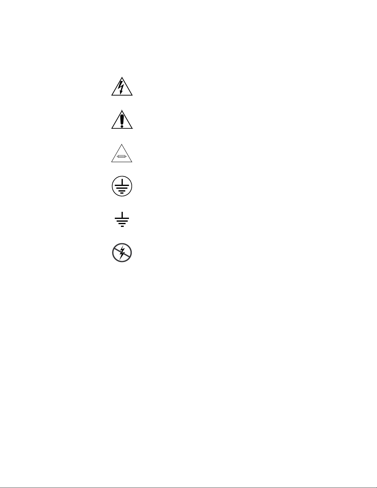
Symbols on the Product
The following symbols may appear on the product:
Indicates that dangerous high voltage is present within the
equipment enclosure that may be of sufficient magnitude to
constitute a risk of electric shock.
Indicates that user, operator or service technician should refer
to product manual(s) for important operating, maintenance,
or service instructions.
This is a prompt to note fuse rating when replacing fuse(s).
The fuse referenced in the text must be replaced with one
having the ratings indicated.
Identifies a protective grounding terminal which must be connected to earth ground prior to making any
connections.
other equipment
Warnings
Identifies an external protective grounding terminal which
may be connected to earth ground as a supplement to an
internal grounding terminal.
Indicates that static sensitive components are present which
may be damaged by electrostatic discharge. Use anti-static
procedures, equipment and surfaces during servicing.
The following warning statements identify conditions or practices that can
result in personal injury or loss of life:
Dangerous voltage or current may be present — Disconnect power and remove
battery (if applicable) before removing protective panels, soldering, or
replacing components.
Do not service alone — Do not internally service this product unless another
person capable of rendering first aid and resuscitation is present.
Remove jewelry — Prior to servicing, remove jewelry such as rings, watches,
and other metallic objects.
Avoid exposed circuitry — Do not touch exposed connections, components or
circuitry when power is present.
11 TRINIX — TMV Installation and Service Manual
Page 12

Safety Summary
Use proper power cord — Use only the power cord supplied or specified for
this product.
Ground product — Connect the grounding conductor of the power cord to
earth ground.
Operate only with covers and enclosure panels in place — Do not operate this
product when covers or enclosure panels are removed.
Use correct fuse — Use only the fuse type and rating specified for this
product.
Use only in dry environment — Do not operate in wet or damp conditions.
Use only in non-explosive environment — Do not operate this product in an
explosive atmosphere.
High leakage current may be present — Earth connection of product is essential
before connecting power.
Dual power supplies may be present — Be certain to plug each power supply
cord into a separate branch circuit employing a separate service ground.
Disconnect both power supply cords prior to servicing.
Cautions
Double pole neutral fusing — Disconnect mains power prior to servicing.
Use proper lift points — Do not use door latches to lift or move equipment.
Avoid mechanical hazards — Allow all rotating devices to come to a stop before
servicing.
The following caution statements identify conditions or practices that can
result in damage to equipment or other property:
Use correct power source — Do not operate this product from a power source
that applies more than the voltage specified for the product.
Use correct voltage setting — If this product lacks auto-ranging power sup-
plies, before applying power ensure that the each power supply is set to
match the power source.
Provide proper ventilation — To prevent product overheating, provide equip-
ment ventilation in accordance with installation instructions.
Use anti-static procedures — Static sensitive components are present which
may be damaged by electrostatic discharge. Use anti-static procedures,
equipment and surfaces during servicing.
TRINIX — TMV Installation and Service Manual 12
Page 13

Safety Summary
Do not operate with suspected equipment failure — If you suspect product damage
or equipment failure, have the equipment inspected by qualified service
personnel.
Ensure mains disconnect — If mains switch is not provided, the power cord(s)
of this equipment provide the means of disconnection. The socket outlet
must be installed near the equipment and must be easily accessible. Verify
that all mains power is disconnected before installing or removing power
supplies and/or options.
Route cable properly — Route power cords and other cables so that they ar not
likely to be damaged. Properly support heavy cable bundles to avoid con
nector damage.
Use correct power supply cords — Power cords for this equipment, if provided,
meet all North American electrical codes. Operation of this equipment at
voltages exceeding 130 VAC requires power supply cords which comply
with NEMA configurations. International power cords, if provided, have
the approval of the country of use.
Use correct replacement battery — This product may contain batteries. To
reduce the risk of explosion, check polarity and replace only with the same
or equivalent type recommended by manufacturer. Dispose of used bat
teries according to the manufacturer’s instructions.
-
-
Troubleshoot only to board level — Circuit boards in this product are densely
populated with surface mount technology (SMT) components and applica
tion specific integrated circuits (ASICS). As a result, circuit board repair at
the component level is very difficult in the field, if not impossible. For war
ranty compliance, do not troubleshoot systems beyond the board level.
-
-
13 TRINIX — TMV Installation and Service Manual
Page 14

Sicherheit – Überblick
Lesen und befolgen Sie die wichtigen Sicherheitsinformationen dieses
Abschnitts. Beachten Sie insbesondere die Anweisungen bezüglich
Brand-, Stromschlag- und Verletzungsgefahren. Weitere spezifische, hier
nicht aufgeführte Warnungen finden Sie im gesamten Handbuch.
WARNUNG Alle Anweisungen in diesem Handbuch, die das Abnehmen der
Geräteabdeckung oder des Gerätegehäuses erfordern, dürfen nur von
qualifiziertem Servicepersonal ausgeführt werden. Um die
Stromschlaggefahr zu verringern, führen Sie keine Wartungsarbeiten
außer den in den Bedienungsanleitungen genannten Arbeiten aus, es sei
denn, Sie besitzen die entsprechende Qualifikationen für diese Arbeiten.
Sicherheit – Begriffe und Symbole
Safety Summary
In diesem Handbuch verwendete Begriffe
Sicherheitsrelevante Hinweise können in diesem Handbuch in der folgenden Form auftauchen:
WARNUNG Warnungen weisen auf Situationen oder Vorgehensweisen hin, die
Verletzungs- oder Lebensgefahr bergen.
VORSICHT Vorsichtshinweise weisen auf Situationen oder Vorgehensweisen hin, die zu
Schäden an Ausrüstungskomponenten oder anderen Gegenständen oder
zum zeitweisen Ausfall wichtiger Komponenten in der Arbeitsumgebung
führen können.
Hinweise am Produkt
Die folgenden Hinweise können sich am Produkt befinden:
GEFAHR — Wenn Sie diesen Begriff lesen, besteht ein unmittelbares Verlet-
zungsrisiko.
WARNUNG — Wenn Sie diesen Begriff lesen, besteht ein mittelbares Verlet-
zungsrisiko.
VORSICHT — Es besteht ein Risiko für Objekte in der Umgebung, den Mixer
selbst oder andere Ausrüstungskomponenten.
TRINIX — TMV Installation and Service Manual 14
Page 15
Safety Summary
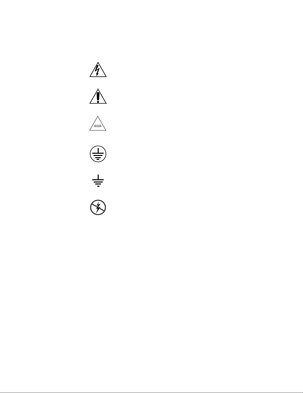
Symbole am Produkt
Die folgenden Symbole können sich am Produkt befinden:
Weist auf eine gefährliche Hochspannung im Gerätegehäuse
hin, die stark genug sein kann, um eine Stromschlaggefahr
darzustellen.
Weist darauf hin, dass der Benutzer, Bediener oder Servicetechniker wichtige Bedienungs-, W
weisungen in den Produkthandbüchern lesen sollte.
Dies ist eine Aufforderung, beim Wechsel von Sicherungen
auf deren Nennwert zu achten. Die im Text angegebene Sicherung muss durch eine Sicherung erse
angegebenen Nennwerte besitzt.
Weist auf eine Schutzerdungsklemme hin, die mit dem
Erdungskontakt verbunden werden muss, bevor weitere Ausrüstungskomponenten angeschlossen werden.
artungs- oder Servicean-
tzt werden, die die
Warnungen
Weist auf eine externe Schutzerdungsklemme hin, die als
Ergänzung zu einem internen Erdungskontakt an die Erde
angeschlossen werden kann.
Weist darauf hin, dass es statisch empfindliche Komponenten
gibt, die durch eine elektrostatische Entladung beschädigt
werden können. Verwenden Sie antistatische Prozeduren,
Ausrüstung und Oberflächen während der Wartung.
Die folgenden Warnungen weisen auf Bedingungen oder Vorgehensweisen
hin, die Verletzungs- oder Lebensgefahr bergen:
Gefährliche Spannungen oder Ströme — Schalten Sie den Strom ab, und ent-
fernen Sie ggf. die Batterie, bevor sie
oder Komponenten austauschen.
Servicearbeiten nicht alleine ausführen — Führen Sie interne Servicearbeiten nur
aus, wenn eine weitere Person anwesend ist, die erste Hilfe leisten und
Wiederbelebungsmaßnahmen einleiten kann.
Schutzabdeckungen abnehmen, löten
Schmuck abnehmen — Legen Sie vor Servicearbeiten Schmuck wie Ringe,
Uhren und andere metallische Objekte ab.
15 TRINIX — TMV Installation and Service Manual
Page 16

Safety Summary
Keine offen liegenden Leiter berühren — Berühren Sie bei eingeschalteter Strom-
zufuhr keine offen liegenden Leitungen, Komponenten oder Schaltungen.
Richtiges Netzkabel verwenden — Verwenden Sie nur das mitgelieferte Netzk-
abel oder ein Netzkabel, das den Spezifikationen für dieses Produkt
entspricht.
Gerät erden — Schließen Sie den Erdleiter des Netzkabels an den Erdung-
skontakt an.
Gerät nur mit angebrachten Abdeckungen und Gehäuseseiten betreiben — Schalten Sie
dieses Gerät nicht ein, wenn die Abdeckungen oder Gehäuseseiten entfernt
wurden.
Richtige Sicherung verwenden — Verwenden Sie nur Sicherungen, deren Typ
und Nennwert den Spezifikationen für dieses Produkt entsprechen.
Gerät nur in trockener Umgebung verwenden — Betreiben Sie das Gerät nicht in
nassen oder feuchten Umgebungen.
Gerät nur verwenden, wenn keine Explosionsgefahr besteht — Verwenden Sie dieses
Produkt nur in Umgebungen, in denen keinerlei Explosionsgefahr besteht.
Hohe Kriechströme — Das Gerät muss vor dem Einschalten unbedingt geerdet
werden.
Doppelte Spannungsversorgung kann vorhanden sein — Schließen Sie die beiden
Anschlußkabel an getrennte Stromkreise an. Vor Servicearbeiten sind beide
Anschlußkabel vom Netz zu trennen.
Zweipolige, neutrale Sicherung — Schalten Sie den Netzstrom ab, bevor Sie mit
den Servicearbeiten beginnen.
Fassen Sie das Gerät beim Transport richtig an — Halten Sie das Gerät beim Trans-
port nicht an Türen oder anderen beweglichen Teilen fest.
Gefahr durch mechanische Teile — Warten Sie, bis der Lüfter vollständig zum
Halt gekommen ist, bevor Sie mit den Servicearbeiten beginnen.
Vorsicht
Die folgenden Vorsichtshinweise weisen auf Bedingungen oder Vorgehensweisen hin, die zu Schäden an Ausrüstungskomponenten oder
anderen Gegenständen führen können:
Gerät nicht öffnen — Durch das unbefugte Öffnen wird die Garantie ungültig.
Richtige Spannungsquelle verwenden — Betreiben Sie das Gerät nicht an einer
Spannungsquelle, die eine höhere Spannung liefert als in den Spezifika
tionen für dieses Produkt angegeben.
TRINIX — TMV Installation and Service Manual 16
-
Page 17

Safety Summary
Gerät ausreichend belüften — Um eine Überhitzung des Geräts zu vermeiden,
müssen die Ausrüstungskomponenten entsprechend den Installationsan
weisungen belüftet werden. Legen Sie kein Papier unter das Gerät. Es
könnte die Belüftung behindern. Platzieren Sie das Gerät auf einer ebenen
Oberfläche.
Antistatische Vorkehrungen treffen — Es gibt statisch empfindliche Kompo-
nenten, die durch eine elektrostatische Entladung beschädigt werden können. Verwenden Sie antistatische Prozeduren, Ausrüstung und
Oberflächen während der Wartung.
CF-Karte nicht mit einem PC verwenden — Die CF-Karte ist speziell formatiert.
Die auf der CF-Karte gespeicherte Software könnte gelöscht werden.
Gerät nicht bei eventuellem Ausrüstungsfehler betreiben — Wenn Sie einen Produk-
tschaden oder Ausrüstungsfehler vermuten, lassen Sie die Komponente
von einem qualifizierten Servicetechniker untersuchen.
Kabel richtig verlegen — Verlegen Sie Netzkabel und andere Kabel so, dass Sie
nicht beschädigt werden. Stützen Sie schwere Kabelbündel ordnungs
gemäß ab, damit die Anschlüsse nicht beschädigt werden.
-
-
Richtige Netzkabel verwenden — Wenn Netzkabel mitgeliefert wurden, erfüllen
diese alle nationalen elektrischen Normen. Der Betrieb dieses Geräts mit
Spannungen über 130 V AC erfordert Netzkabel, die NEMA-Konfigura
tionen entsprechen. Wenn internationale Netzkabel mitgeliefert wurden,
sind diese für das Verwendungsland zugelassen.
Richtige Ersatzbatterie verwenden — Dieses Gerät enthält eine Batterie. Um die
Explosionsgefahr zu verringern, prüfen Sie die Polarität und tauschen die
Batterie nur gegen eine Batterie desselben Typs oder eines gleichwertigen,
vom Hersteller empfohlenen Typs aus. Entsorgen Sie gebrauchte Batterien
entsprechend den Anweisungen des Batterieherstellers.
Das Gerät enthält keine Teile, die vom Benutzer gewartet werden können.
Wenden Sie sich bei Problemen bitte an den nächsten Händler.
-
17 TRINIX — TMV Installation and Service Manual
Page 18

Consignes de sécurité
Il est recommandé de lire, de bien comprendre et surtout de respecter les
informations relatives à la sécurité qui sont exposées ci-après, notamment
les consignes destinées à prévenir les risques d’incendie, les décharges élec
triques et les blessures aux personnes. Les avertissements complémentaires, qui ne sont pas nécessairement repris ci-dessous, mais présents dans
toutes les sections du manuel, sont également à prendre en considération.
AVERTISSEMENT Toutes les instructions présentes dans ce manuel qui concernent
l’ouverture des capots ou des logements de cet équipement sont
destinées exclusivement à des membres qualifiés du personnel de
maintenance. Afin de diminuer les risques de décharges
électriques, ne procédez à aucune intervention d’entretien autre
que celles contenues dans le manuel de l’utilisateur, à moins que
vous ne soyez habilité pour le faire.
Safety Summary
-
Consignes et symboles de sécurité
Termes utilisés dans ce manuel
Les consignes de sécurité présentées dans ce manuel peuvent apparaître
sous les formes suivantes:
AVERTISSEMENT Les avertissements signalent des conditions ou des pratiques
susceptibles d’occasionner des blessures graves, voire même
fatales.
ATTENTION Les mises en garde signalent des conditions ou des pratiques
susceptibles d’occasionner un endommagement à l’équipement ou
aux installations, ou de rendre l’équipement temporairement non
opérationnel, ce qui peut porter préjudice à vos activités.
Signalétique apposée sur le produit
La signalétique suivante peut être apposée sur le produit:
DANGER — risque de danger imminent pour l’utilisateur.
AVERTISSEMENT — Risque de danger non imminent pour l’utilisateur.
MISE EN GARDE — Risque d’endommagement du produit, des installations
ou des autres équipements.
TRINIX — TMV Installation and Service Manual 18
Page 19
Safety Summary
Symboles apposés sur le produit
Les symboles suivants peut être apposés sur le produit:
Signale la présence d’une tension élevée et dangereuse dans le
boîtier de l’équipement ; cette tension peut être suffisante
pour constituer un r
Signale que l’utilisateur, l’opérateur ou le technicien de maintenance doit faire référence au(
naissance des instructions d’uti
d’entretien.
Il s’agit d’une invite à prendre note du calibre du fusible lors
du remplacement de ce dernier. Le fusible auquel il est fait
référence dans le texte doit être remplacé par un fusible du
même calibre.
Identifie une borne de protection de mise à la masse qui doit
être raccordée correctement avant de procéder au raccordement des autres équipements.
isque de décharge électrique.
x) manuel(s) pour prendre con-
lisation, de maintenance ou
Avertissements
Identifie une borne de protection de mise à la masse qui peut
être connectée en tant que borne de mise à la masse supplémentaire.
Signale la présence de composants sensibles à l’électricité statique et qui sont susceptibles d’ê
décharge électrostatique. Utilisez des procédures, des équipements et des surfaces antistatique
d’entretien.
Les avertissements suivants signalent des conditions ou des pratiques susceptibles d’occasionner des blessures graves, voire même fatales:
Présence possible de tensions ou de courants dangereux — Mettez hors tension,
débranchez et retirez la pile (le cas échéant) avant de déposer les couvercles
de protection, de défaire une soudure ou de remplacer des composants.
Ne procédez pas seul à une intervention d’entretien — Ne réalisez pas une interven-
tion d’entretien interne sur ce produit
pour fournir les premiers soins en cas d’accident.
si une personne n’est pas présente
tre endommagés par une
s durant les interventions
Retirez tous vos bijoux — Avant de procéder à une intervention d’entretien,
retirez tous vos bijoux, notamment les bagues, la montre ou tout autre objet
métallique.
19 TRINIX — TMV Installation and Service Manual
Page 20

Safety Summary
Évitez tout contact avec les circuits exposés — Évitez tout contact avec les connex-
ions, les composants ou les circuits exposés s’ils sont sous tension.
Utilisez le cordon d’alimentation approprié — Utilisez exclusivement le cordon
d’alimentation fourni avec ce produit ou spécifié pour ce produit.
Raccordez le produit à la masse — Raccordez le conducteur de masse du cordon
d’alimentation à la borne de masse de la prise secteur.
Utilisez le produit lorsque les couvercles et les capots sont en place — N’utilisez pas
ce produit si les couvercles et les capots sont déposés.
Utilisez le bon fusible — Utilisez exclusivement un fusible du type et du
calibre spécifiés pour ce produit.
Utilisez ce produit exclusivement dans un environnement sec — N’utilisez pas ce
produit dans un environnement humide.
Utilisez ce produit exclusivement dans un environnement non explosible — N’utilisez
pas ce produit dans un environnement dont l’atmosphère est explosible.
Présence possible de courants de fuite — Un raccordement à la masse est indis-
pensable avant la mise sous tension.
Mises en garde
Deux alimentations peuvent être présentes dans l’équipement — Assurez vous que
chaque cordon d’alimentation est raccordé à des circuits de terre séparés.
Débranchez les deux cordons d’alimentation avant toute intervention.
Fusion neutre bipolaire — Débranchez l’alimentation principale avant de pro-
céder à une intervention d’entretien.
Utilisez les points de levage appropriés — Ne pas utiliser les verrous de la porte
pour lever ou déplacer l’équipement.
Évitez les dangers mécaniques — Laissez le ventilateur s’arrêter avant de pro-
céder à une intervention d’entretien.
Les mises en garde suivantes signalent les conditions et les pratiques susceptibles d’occasionner des endommagements à l’équipement et aux installations:
N’ouvrez pas l’appareil — Toute ouverture prohibée de l’appareil aura pour
effet d’annuler la garantie.
Utilisez la source d’alimentation adéquate — Ne branchez pas ce produit à une
source d’alimentation qui utilise une tension supérieure à la tension nomi
nale spécifiée pour ce produit.
TRINIX — TMV Installation and Service Manual 20
-
Page 21

Safety Summary
Assurez une ventilation adéquate — Pour éviter toute surchauffe du produit,
assurez une ventilation de l’équipement conformément aux instructions
d’installation. Ne déposez aucun document sous l’appareil — ils peuvent
gêner la ventilation. Placez l’appareil sur une surface plane.
Utilisez des procédures antistatiques - Les composants sensibles à l’électricité
statique présents dans l’équipement sont susceptibles d’être endommagés
par une décharge électrostatique. Utilisez des procédures, des équipements
et des surfaces antistatiques durant les interventions d’entretien.
N’utilisez pas la carte CF avec un PC — La carte CF a été spécialement formatée.
Le logiciel enregistré sur la carte CF risque d’être effacé.
N’utilisez pas l’équipement si un dysfonctionnement est suspecté — Si vous sus-
pectez un dysfonctionnement du produit, faites inspecter celui-ci par un
membre qualifié du personnel d’entretien.
Acheminez les câbles correctement — Acheminez les câbles d’alimentation et les
autres câbles de manière à ce qu’ils ne risquent pas d’être endommagés.
Supportez correctement les enroulements de câbles afin de ne pas endom
mager les connecteurs.
-
Utilisez les cordons d’alimentation adéquats — Les cordons d’alimentation de cet
équipement, s’ils sont fournis, satisfont aux exigences de toutes les régle
mentations régionales. L’utilisation de cet équipement à des tensions
dépassant les 130
aux exigences des configurations NEMA. Les cordons internationaux, s’ils
sont fournis, ont reçu l’approbation du pays dans lequel l’équipement est
utilisé.
Utilisez une pile de remplacement adéquate — Ce produit renferme une pile. Pour
réduire le risque d’explosion, vérifiez la polarité et ne remplacez la pile que
par une pile du même type, recommandée par le fabricant. Mettez les piles
usagées au rebut conformément aux instructions du fabricant des piles.
Cette unité ne contient aucune partie qui peut faire l’objet d’un entretien
par l’utilisateur. Si un problème survient, veuillez contacter votre distribu
teur local.
V en c.a. requiert des cordons d’alimentation qui satisfont
-
-
21 TRINIX — TMV Installation and Service Manual
Page 22

Regulatory Notices
Certifications and Compliances
FCC Emission Control
This equipment has been tested and found to comply with the limits for a
Class A digital device, pursuant to Part 15 of the FCC Rules. These limits
are designed to provide reasonable protection against harmful interference
when the equipment is operated in a commercial environment. This equip
ment generates, uses, and can radiate radio frequency energy and, if not
installed and used in accordance with the instruction manual, may cause
harmful interference to radio communications. Operation of this equip
ment in a residential area is likely to cause harmful interference in which
case the user will be required to correct the interference at his own expense.
Changes or modifications not expressly approved by Grass Valley can
affect emission compliance and could void the user’s authority to operate
this equipment.
-
-
Canadian EMC Notice of Compliance
This digital apparatus does not exceed the Class A limits for radio noise
emissions from digital apparatus set out in the Radio Interference Regula
tions of the Canadian Department of Communications.
Le présent appareil numérique n’emet pas de bruits radioélectriques
dépassant les limites applicables aux appareils numeriques de la classe A
préscrites dans le Règlement sur le brouillage radioélectrique édicte par le
ministère des Communications du Canada.
EN55022 Class A Warning
In a domestic environment, products that comply with Class A may cause
radio interference in which case the user may be required to take adequate
measures.
-
TRINIX — TMV Installation and Service Manual 22
Page 23

Regulatory Notices
Canadian Certified Power Cords
Canadian Certified AC Adapter
Laser Compliance
Laser Safety Requirements
Canadian approval includes the products and power cords appropriate for
use in the North America power network. All other power cords supplied
are approved for the country of use.
Canadian approval includes the AC adapters appropriate for use in the
North America power network. All other AC adapters supplied are
approved for the country of use.
The device used in this product is a Class 1 certified laser product. Operating this product outside specifications or altering from its original design
may result in hazardous radiation exposure, and may be considered an act
of modifying or new manufacturing of a laser product under U.S. regula
tions contained in 21CFR Chapter 1, subchapter J or CENELEC regulations
in HD 482 S1. People performing such an act are required by law to recertify
and reidentify this product in accordance with provisions of 21CFR sub
chapter J for distribution within the U.S.A., and in accordance with
CENELEC HD 482 S1 for distribution within countries using the IEC 825
standard.
-
-
Laser Safety
Laser safety in the United States is regulated by the Center for Devices and
Radiological Health (CDRH). The laser safety regulations are published in
the “Laser Product Performance Standard,” Code of Federal Regulation
(CFR), Title 21, Subchapter J.
The International Electrotechnical Commission (IEC) Standard 825, “Radiation of Laser Products, Equipment Classification, Requirements and
User’s Guide,” governs laser products outside the United States. Europe
and member nations of the European Free Trade Association fall under the
jurisdiction of the Comite European de Normalization Electrotechnique
(CENELEC).
For the CDRH: The radiant power is detected through a 7 mm aperture at
a distance of 200 mm from the source focused through a lens with a focal
length of 100 mm.
For IEC compliance: The radiant power is detected through a 7 mm aperture at a distance of 100 mm from the source focused through a lens with a
focal length of 100 mm.
23 TRINIX — TMV Installation and Service Manual
Page 24

FCC Emission Limits
Certifications:
Category Standard Designed/tested for compliance with:
ANSI / UL60950 “Standard for Safety of Information Technology Equipment - Safety - Part 1: General
IEC 60950 “Standard for Safety for Information Technology Equipment - Safety - Part 1: General
Safety
EMI
CAN/CSA C22.2, No. 60950 “Standard for Safety of Information Technology Equipment - Safety - Part 1: General
EN60950 Safety of Information Technology Equipment, including Electrical Business Equipment.
73/23/EEC Low Voltage Directive
EMC Directive 89/336/EEC via
EN 55103-1 and 2
EN 55103-1 standards Electromagnetic compatibility.
EN55103-2 standards Electromagnetic compatibility--Product family standard for audio, video, audio-visual
US FCC Class A
Canada FCC Industry Canada
Australia & New Zealand: AS/NZS 3548
Regulatory Notices
This device complies with Part 15 of the FCC Rules. Operation is subject to
the following two conditions: (1) This device may not cause harmful inter
ference, and (2) this device must accept any interference received,
including interference that may cause undesirable operation. This device
has been tested and found to comply with FCC Part 15 Class B limits for a
digital device when tested with a representative laser-based fiber optical
system that complies with ANSI X3T11 Fiber Channel Standard.
Requirements”, (ANSI/UL 60950-1, First Edition, Dated April 1, 2003, with revision
through and including November 26, 2003.)
Requirements”, (IEC 60950-1, First Edition, 2001, Corrigendum 1:10-2002)
Requirements”, (CAN/CSA-C22.2 No. 60950-1-03. First Edition Dated April 1, 2003,
with revisions through and including November 26, 2003)
Audio, Video and Entertainment Lighting Control for the European Community.
Product family standard for audio, video, audio-visual and entertainment lighting control
apparatus for professional use.
Part 1 Emissions, Environment E1/E2
EN 55022: Class A Radiated and Conducted Emissions
EN 61000-3-2: Power Line Harmonic Emissions, Radiated Magnetic Field Emissions,
Peak Inrush Current
and entertainment lighting control apparatus for professional use.
Part 2 Immunity, Environment E1/E2
EN 50082-1: Immunity
EN 61000-4-2:
Electrostatic Discharge “ESD” Immunity
EN 61000-4-3:
Radiated RF Electromagnetic Field Immunity
EN 61000-4-4:
Electrical Fast Transient/Burst “EFT” Immunity
EN 61000-4-5: Surge Immunity
EN 61000-4-6: Conducted RF Immunity
EN 61000-4-11: Voltage Dips, Short Interruptions and Voltage Variations
Annex A - Radiated Magnetic Field Immunity
Note: This only applies to assemblies sensitive to magnetic fields
CISPR Pub. 22 (1985)
-
Category Standard Designed/tested for compliance with:
Safety UL1419 Professional Video and Audio Equipment
TRINIX — TMV Installation and Service Manual 24
Page 25

Regulatory Notices
25 TRINIX — TMV Installation and Service Manual
Page 26

ESD Protection
Electronics today are more susceptible to electrostatic discharge (ESD)
damage than older equipment. Damage to equipment can occur by ESD
fields that are smaller than you can feel. Implementing the information in
this section will help you protect the investment that you have made in
purchasing Grass Valley equipment. This section contains Grass Valley’s
recommended ESD guidelines that should be followed when handling
electrostatic discharge sensitive (ESDS) items. These minimal recommen
dations are based on the information in the Sources of ESD and Risks area.
The information in Grounding Requirements for Personnel on page 28 is provided to assist you in selecting an appropriate grounding method.
Recommended ESD Guidelines
Follow these guidelines when handling Grass Valley equipment:
• Only trained personnel that are connected to a grounding system
should handle ESDS items.
• Do not open any protective bag, box, or special shipping packaging
until you have been grounded.
-
Note When a Personal Grounding strap is unavailable, as an absolute minimum,
touch a metal object that is touching the floor (for example, a table, frame, or
rack) to discharge any static energy before touching an ESDS item.
• Open the anti-static packaging by slitting any existing adhesive tapes.
Do not tear the tapes off.
• Remove the ESDS item by holding it by its edges or by a metal panel.
• Do not touch the components of an ESDS item unless it is absolutely
necessary to configure or repair the item.
• Keep the ESDS work area clear of all nonessential items such as coffee
cups, pens, wrappers and personal items as these items can discharge
static. If you need to set an ESDS item down, place it on an anti-static
mat or on the anti-static packaging.
TRINIX — TMV Installation and Service Manual 26
Page 27

ESD Protection
Sources of ESD and Risks
The following information identifies possible sources of electrostatic discharge and can be used to help establish an ESD policy.
Personnel
One of the largest sources of static is personnel. The static can be released
from a person’s clothing and shoes.
Environment
The environment includes the humidity and floors in a work area. The
humidity level must be controlled and should not be allowed to fluctuate
over a broad range. Relative humidity (RH) is a major part in determining
the level of static that is being generated. For example, at 10% - 20% RH a
person walking across a carpeted floor can develop 35kV; yet when the rel
ative humidity is increased to 70% - 80%, the person can only generate
1.5kV.
-
Static is generated as personnel move (or as equipment is moved) across a
floor’s surface. Carpeted and waxed vinyl floors contribute to static build
up.
Work Surfaces
Painted or vinyl-covered tables, chairs, conveyor belts, racks, carts, anodized surfaces, plexiglass covers, and shelving are all static generators.
Equipment
Any equipment commonly found in an ESD work area, such as solder
guns, heat guns, blowers, etc., should be grounded.
Materials
Plastic work holders, foam, plastic tote boxes, pens, packaging containers
and other items commonly found at workstations can generate static elec
tricity.
-
27 TRINIX — TMV Installation and Service Manual
Page 28
Grounding Requirements for Personnel
The information in this section is provided to assist you in selecting a
grounding method. This information is taken from ANSI/ESD S20.20-2007
(Revision of ANSI/ESD S20.20-1999).
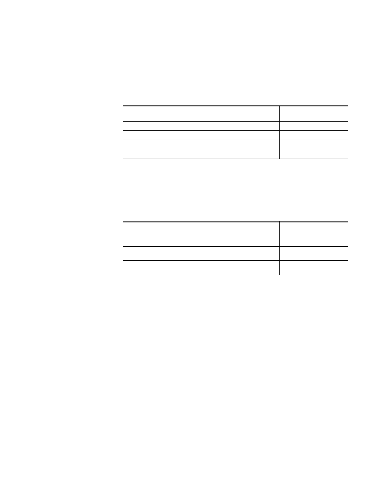
Table 1. Product Qualification
Personnel Grounding Technical
Requirement
Wrist Strap System* ANSI/ESD S1.1 (Section 5.11) < 3.5 x 10⁷ ohm
Flooring / Footwear System – Method 1 ANSI/ESD STM97.1 < 3.5 x 10
Flooring / Footwear System – Method 2
(both required)
ANSI/ESD STM97.1
ANSI/ESD STM97.2
Product qualification is normally conducted during the initial selection of
ESD control products and materials. Any of the following methods can be
used: product specification review, independent laboratory evaluation, or
internal laboratory evaluation.
Test Method Required Limits
9
< 10
< 100 V
ESD Protection
7
ohm
ohm
Table 2. Compliance Verification
Personnel Grounding Technical
Requirement
Wrist Strap System* ESD TR53 Wrist Strap Section < 3.5 x 10⁷ ohm
Flooring / Footwear System – Method 1 ESD TR53 Flooring Section and ESD
Flooring / Footwear System – Method 2
(both required)
TR53 Footwear Section
ESD TR53 Flooring Section and ESD
TR53 Footwear Section
Test Method Required Limits
< 3.5 x 10
< 1.0 x 10
7
ohm
9
ohm
* For situations where an ESD garment is used as part of the wrist strap
grounding path, the total system resistance, including the person, garment,
7
and grounding cord, must be less than 3.5 x 10
ohm.
TRINIX — TMV Installation and Service Manual 28
Page 29

ESD Protection
29 TRINIX — TMV Installation and Service Manual
Page 30

Overview
The Trinix Multiviewer (TMV) is a flexible and configurable multiviewer
solution that has been integrated into the Trinix NXT router. The TMV is for
displaying multiple video images, time, audio activity, and so forth, on dis
plays located at the customer’s facility.
The TMV board occupies an output slot in a Trinix Routing switcher. The
TMV board takes advantage of the routing switcher's power and cooling
features. However, the router control system considers it an external
device. This simplified approach improves reliability of the system and
saves the cost of an output card, another external frame, and cabling. The
TMV board is hot swappable, which makes board replacement a quick and
easy task with minimal downtime.
Each TMV board can use the standard base-band video formats that are
supported by the Trinix NXT router through 32 input and eight (8) output
connectors. The 32 destinations act as 32 inputs to the TMV board. The dis
played information can be cascaded to other boards to provide increased
display density on a single display. There is a 1- frame delay when video is
processed but it is processed only one time.
Section 1
-
-
The TMV board performs more processing than a Trinix output board,
which means it requires more power and cooling. There are limitations
when adding the TMV to an existing symmetrical Trinix NXT frame. For
more information, see
TRINIX - TMV Installation and Service Manual 30
Hardware Installation on page 34.
Page 31

Section 1 — Overview
TMV Compatibility
Control System
The Trinix Multiviewer is compatible with:
• Trinix NXT (Broadlinx 3.3.0 and newer)
•Sonata
•Apex
• Encore (Version 1.8.2 and newer)
• Jupiter AccuSwitch (Version 7.9.1 and newer)
• NetConfig (Version 2.0.13 and newer)
• TSL (Protocol V5.0 UDP)
• Image Video (RDU 1100 TCP)
The Trinix Multiviewer product integrates with a router control system
using Native Protocol. The Trinix Multiviewer board inputs are configured
as router destinations and can be controlled by any control panel that has
access to those destinations.
Either Grass Valley's Jupiter AccuSwitch, or Encore control systems may be
used with the Trinix Multiviewer board. The following versions of the
Grass Valley control systems are the minimum required to use the Trinix
Multiviewer:
• Encore 1.8.2
• AccuSwitch 7.9.1
Future releases of these programs will support the TMV.
Network Control
The Trinix Multiviewer requires two network connections; one named
CNTL (control) and one named FAC (facility). The Facility LAN is used to
communicate with external TMV components. For example, Router
Control System (via Native Protocol), logging, and Tally. The Control LAN
is used to communicate with the TMV components. For example, the TMV
Control application and the TMV Configuration Editor application.
31 TRINIX TMV Installation and Service Manual
Page 32

Figure 1. The LANS Used by the TMV Board
Input card(s)
Output card(s)
TMV board(s)
Broadlinx
Router
Control System
(Jupiter/Encore)
Control
LAN
Facility
LAN
Utility PC
Software Updates
Configuration
First Birthday
NetConfig
GUI Application
Trinix Frame
Monitor(s)
TMV Video Out
Video Sources
The Facility LAN is used to communicate with the following:
• Native Protocol (Router Control Systems)
•NetConfig
• Tally system (optional)
• TMV logging information
The Control LAN is used to communicate with the following:
• TMV Configuration Editor
• TMV Control application
1694a cables must be used. These cables should be longer than 10 M but less
than 100 M (Greater than 30 ft. but less than 300 ft.) for re-entry into the
routing switcher.
Using HDMI Converters
Grass Valley recommends that all HDMI converters that are used in a TMV
system should be 1080p (3Gb/s) compatible. The TMV board supports and
can be configured to provide the 1080p 3Gb/s video standard as an output.
HDMI converters must be 3Gb/s compatible if you are using 3 Gb/s
boards in the system. This converter is connected to a Trinix 3Gb/s
HO33300 Output board or a TMV output that has been configured for the
1080p video standard.
TRINIX TMV Installation and Service Manual 32
Page 33

Section 1 — Overview
Trinix Multiviewer Configuration Editor
Trinix Multiviewer Controller
The following HDMI Converters have been tested:
• Grass Valley's HDMI converters (ADVC-G3 and ADVC-G4)
• AJA Hi5-3G
• BrightEye 72 3G/HD/SD.
The Trinix Multiviewer Configuration Editor is a graphical user interface
(GUI) that allows you to configure both the monitor wall and individual
monitor layout. The tile size is flexible with automatic aspect ratios.
The Trinix Multiviewer Controller is a graphical user interface (GUI) that
allows you to oversee the monitors on the monitor wall. You may also
retrieve the layout from a TMV board and set the monitor bezel. The mul
tiviewer’s System clocks may be set using the Controller.
-
PC Requirements
A PC is required to run the Trinix Multiviewer Controller and Editor programs. Ensure that the PC has the following minimum requirements before
installing the TMV applications:
• Windows 7 (English version)
• Multi-core processor
•3 GB of RAM
• 160 GB Hard Disk
•CD-ROM drive
• Two 1 GB NIC connections
• Monitor with a 1600x1200 resolution
Note Redundant PCs are not supported.
33 TRINIX TMV Installation and Service Manual
Page 34

Hardware Installation
Overview
The Trinix Multiviewer (TMV) boards are installed inside a Trinix NXT
router frame in a similar manner as a standard Trinix NXT output card;
however, the TMV boards use a different rear panel. TMV boards are
installed from the front of the router and are locked into place to prevent
the boards from becoming loose if they are installed in a production truck.
The TMV board is hot swappable to provide quick and easy replacement
with minimal downtime. The TMV board supports 32 inputs and 8 outputs
and is capable of utilizing all the standard base-band video formats that are
supported by the Trinix NXT router.
Each TMV board has four video processors that can support up to eight
monitor video inputs. Each video processor manages eight video inputs.
These video inputs are managed by the configuration editor to create your
preferred display.
Section 2
Outputs on the TMV card can be wired as inputs to the Trinix. Monitors can
be wired as outputs from the Trinix. Wiring a system in this manner will
allow for routing any TMV output to any monitor. A 1694a cable must be
used. This cable
the routing switcher.
must be no less than 10 Meters (32.8 Feet) for re-entering
Supported Number of Boards per Router Frame
The TMV board performs more processing than a Trinix output board,
which means it requires more power and cooling. This increased power
and cooling limits the number of boards and in which slot a TMV may be
used in a routing switcher.
TRINIX — TMV Installation and Service Manual 34
Page 35

Section 2 — Hardware Installation
Trinix Asymmetrical Frames
The Trinix asymmetrical frames will support the following number of
Trinix boards:
• 128 x 256 supports up to 8 TMV boards
• 256 x 512 supports up to 8 TMV boards
• 512 x 1024 supports up to 16 TMV boards
Trinix Symmetrical Frames
The TMV output boards may also be used in existing symmetrical Trinix
NXT frames but in a limited manner. Due to the increased power and
cooling requirements, an extra space next to each TMV board is required
for ventilation.
The supported number of TMV boards in an existing symmetrical Trinix
NXT frame is:
• 128x128 supports up to 2 TMV boards
• 256x256 supports up to 4 TMV boards
• 512x512 supports up to 4 TMV boards
TMV Board Location
The TMV board may be placed in any Output slot for the 128x256 and the
512x1024 Trinix Routing switchers. Grass Valley recommends that you
ONLY install the TMV board in the following output ranges of the identi
fied routing switchers. See Tab le 3 for more information
The boards may be installed in any of the allowed slots identified but
MUST cascade in ascending order. They do not have to be installed begin
ning with the first available output slot and slots may be skipped.
Table 3. Recommended TMV Location
Routing Switcher
Size
256x512 Jupiter: 128-159, 160-191, 192-223, 224-255, 256-287, 288-319, 320-351, and 352-383,
128x128
* Jupiter: 0-31 and 64-95 only.
256x256
* Jupiter: 0-31, 64-95, 128-159, and 192-223 only.
512x512
* Jupiter: 0-31, 64-95, 128-159, and 192-223 only.
-
-
Output Range
Encore: 129-160, 161-192, 193-224, 225-256, 257-288, 289-320, 321-352, and 353-384
Encore: 1-32 and 65-96 only.
Encore: 1-32, 65-96, 129-160, and 193-224 only.
Encore: 1-32, 65-96, 129-160, and 193-224 only.
35 TRINIX — TMV Installation and Service Manual
Page 36

Overview
071873500_128x256_Slotmap-TMV-board
* Each TMV board will need two slots if it is installed in a symmetrical frame.
The TMV boards must be placed in an Output board slot. The following
examples show the location for the TMV board for the specific routing
switcher. The correct slots that may be used are shown in gray.
TMV Location in the 128x256 Routing Switcher on
TMV Location in the 256x512 Routing Switcher on
TMV Location in the 512x1024 Routing Switcher on page 38
TMV Location in the 128x128 Routing Switcher on
TMV Location in the 256x256 Routing Switcher on
TMV Location in the 512x512 Routing Switcher on
TMV Location in the 128x256 Routing Switcher
page 36
page 37
page 40
page 41
page 42
The 128x256 routing switcher has the capacity for eight (8) TMV boards. No
ventilation slots are required.
Place board in the four (4) slots in the outer r
outer left Output slots.
TRINIX — TMV Installation and Service Manual 36
ight and the four (4) to the
Page 37

Section 2 — Hardware Installation
TMV Location in the 256x512 Routing Switcher
071873500_256x512-Slotmap-TMV board.
The 256x512 routing switcher has the capacity for eight (8) TMV boards. No
open slots for ventilation are required. Place the TMV boards in the upper
Output slots.
Note The lower Output slots are reserved; Do NOT place TMV boards in this area.
37 TRINIX — TMV Installation and Service Manual
Page 38

TMV Location in the 512x1024 Routing Switcher
071873500_512x1024_slot_tmv board
Overview
TRINIX — TMV Installation and Service Manual 38
Page 39

Section 2 — Hardware Installation
The 512x1024 routing switcher has a restriction of 16 boards maximum.
This frame does not require open slots for ventilation purposes.
The maximum 16 TMV boards can be placed in any Output slot; however,
Grass Valley recommends using one of the following configurations:
• 8 in Upper half and 8 in the Lower half (can be distributed according
to your needs)
• 16 in Upper half
• 16 in Lower half
For power efficiency, place eight (8) TMV boards in the upper half and eight
(8) boards in the lower half (Shown in
Switcher on page 38).
TMV Location in the 512x1024 Routing
39 TRINIX — TMV Installation and Service Manual
Page 40

TMV Location in the 128x128 Routing Switcher
FAN ALARM
FAN ALARM
071873500_128x128_TMV-board
EMPTY SLOT
EMPTY SLOT
The 128 routing switcher has the capacity for two (2) TMV boards.
Overview
The TMV boards occupy the
space available.
upper Output slots, each with one (1) empty
TRINIX — TMV Installation and Service Manual 40
Page 41

Section 2 — Hardware Installation
TMV Location in the 256x256 Routing Switcher
DC
AC DCOKAC
VADJ
OK
OK
VADJ
OK
FAN ALARM
EMPTY SLOT
FAN ALARM
EMPTY SLOT
FAN ALARM
EMPTY SLOT
EMPTY SLOT
The 256x256 routing switcher has capacity for four (4) TMV boards.
Each MV board requires one (1) open Output slot
to allow for ventilation.
071873500_256x256 TMV-board.
41 TRINIX — TMV Installation and Service Manual
Page 42

TMV Location in the 512x512 Routing Switcher
VADJ
OK
OK
DCAC
VADJ
OK
AC
OK
DC
PRIMARY
SECONDARY
ACDC
OKOK
VADJ
PS CPS A
DCAC
OKOK
VADJ
PS DPS B
Overview
481 - 512
FAN ALARM
INPUTSINPUTS
449 - 480
FAN A
INPUTS
FAN ALARM
FAN B
417 - 448
385 - 416 225 - 256 193 - 224 161 - 192
FAN ALARM
EMPTY SLOT
OUTPUTS
OUTPUTSOUTPUTSINPUTSINPUTS
FAN C
EMPTY SLOT
129 - 160
OUTPUTS
INPUTS 257 - 512 / OUTPUTS 1 - 256
INPUTS 257 - 512 / OUTPUTS 257 - 512
FAN ALARM
OUTPUTSOUTPUTS
97 - 128
INPUTS 1 - 256 / OUTPUTS 1 - 256
FAN ALARM
EMPTY SLOT
EMPTY SLOT
OUTPUTS
OUTPUTS
OUTPUTS
1 - 3233 - 64
65 - 96
FAN ALARM
FAN F
FAN EFAN D
POWER ALARM IFC
65 - 96 33 - 6497 - 128
INPUTS
INPUTSINPUTSINPUTS
1 - 32
INPUTS
INPUTS 1 - 256 / OUTPUTS 257 - 512
INPUTS
353 - 384
INPUTS
OUTPUTSINPUTS
INPUTSINPUTS
353 - 384
257 - 288289 - 320321 - 352
OUTPUTS
321 - 352
OUTPUTS
289 - 320
OUTPUTS
OUTPUTS
257 - 288
OUTPUTS
481 -512
OUTPUTS OUTPUTS
417 - 448449 - 480
OUTPUTS
385 - 416
INPUTS
INPUTSINPUTS
INPUTS
INPUTS
129 - 160
161 - 192
193 - 224225 - 256
071873500_512x512_TMV-board
TRINIX — TMV Installation and Service Manual 42
Page 43

Section 2 — Hardware Installation
The 512x512 routing switcher can contain up to four (4) TMV boards.
Each board requires an open output slot to allow for ventilation. Place the
TMV boards in the upper Output slots.
Note The lower Output slots are reserved; Do NOT place TMV boards in this area.
43 TRINIX — TMV Installation and Service Manual
Page 44

Installing the Trinix Multiviewer Board
The following is a summary of the steps needed for installation of the Trinix
Multiviewer.
• Unpacking and Inspection
• Installing the Trinix Multiviewer Option
Unpacking and Inspection
Before unpacking the equipment, inspect the shipping carton for evidence
of freight damage. Notify the carrier and Grass Valley if the contents have
been damaged. Retain all shipping cartons and padding material for
inspection by the carrier.
Do NOT return damaged merchandise to Grass Valley until an appropriate
claim has been filed with the carrier and you have received a material
return authorization number from Grass Valley.
Installing the Trinix Multiviewer Board
Installing the Trinix Multiviewer
The TMV boards are sensitive to ESD. Use static handling precautions
when installing or removing the TMV. See
more information.
If you purchased the Trinix Multiviewer (TMV) option with a Trinix
Routing switcher, the boards will be installed at the factory. You will only
need to install the TMV boards on-site if they are to be used in an existing
routing switcher, or used as a replacement.
Installing the TMV requires that you remove the standard BNC rear panel
and Output boards, if they are present in the locations specified in
Board Location. The TMV Rear panels will then be installed in the rear of the
frame. The TMV board is installed and locked into place from the front of
the Trinix frame. Ensure that the TMV board is installed in the appropriate
slot in the Trinix routing switcher. See
card slot number is important since the TMV destinations are determined
by the Routing switcher’s card slot, which is the same as a Trinix output
card.
Before starting this procedure, remove the Output boards from the front of
the routing switcher and then move to the rear of the router.
ESD Protection on page 26 for
TMV
TMV Board Location on page 35. The
TRINIX — TMV Installation and Service Manual 44
Page 45

Section 2 — Hardware Installation
Remove the top screw
Remove the bottom
screw
Follow these steps to install the Trinix Multiviewer option:
1. Remove the standard Output BNC rear panel from the rear of the Trinix
frame.
a. Remove the top and bottom screw for the rear panel (Figure 2).
Figure 2. Remove the Screws from the Standard Rear Panel
Hold the rear panel in place to prevent possible damage from
falling.
2. Place the TMV rear panel into the slot where the BNC rear panel was
3. Fasten the rear panel to the frame using the provided screws (Figure 3
071827612_Fiber_Inst_BNC
b. Remove the Output BNC rear panel from the frame.
removed.
on page 46).
45 TRINIX — TMV Installation and Service Manual
Page 46

Installing the Trinix Multiviewer Board
Insert the top screw
Insert the bottom
screw
Figure 3. Install the Screws for the TMV Rear Panel
071873500_TMV-Rear-pnl-connections
4. Locate the front Output slot corresponding to the TMV rear panel.
5. Insert the TMV boards into their corresponding locations from the front
of the Trinix frame and then lock them into place.
a. To insert the boards, carefully slide the TMV board along the board
guides, keep the ejector levers spread apart; slide the board in until
the levers make contact.
b. Fold the levers toward each other until the front ejector levers snap
into place, which will lock the board into the frame.
Note If you are adding the Trinix Multiviewer to a symmetrical Trinix NXT frame
(that is, 128x128, 256x256, or 512x512), an added space between TMV
boards is required. See TMV Board Location on page 35 for more information.
6. Close the Trinix routing switcher’s door. Keep the routing switcher’s
door closed during operation to maintain optimum cooling conditions.
TRINIX — TMV Installation and Service Manual 46
Page 47

Section 2 — Hardware Installation
Connect the
Network Connections
Connect the
Reference Connections
Connect the
MADI Audio
Connections
Connect the
Monitor Outs
Connections
Connect the
Cascade Connections
TMV Rear Panel Connections
The rear panel of the Trinix Multiviewer has five different types of connectors:
• Network connections
• Reference connections
• Audio connections
• Monitor connections
• Cascading connections
Each of these connections will be explained below.
Figure 4. TMV Rear Panel - Connections
Note The example in Figure 4 is for demonstration purposes; the rear panel will be
horizontal in the 128x128 frame. When it is installed in all other Trinix frames,
the rear panel will be similar to the example shown in Figure 3 on page 46.
Network Connections
Two Network connectors on the TMV's rear panel are labeled FAC and
CNTL. The CNTL connection is for items within the TMV network that you
want to view, monitor, or control using the TMV applications. The FAC
connection is for working with other systems within your local network;
for example, a router control system.
Follow these steps to connect the Network connections on the TMV:
1. Connect the TMV network’s CAT 5 cable to the CNTL connection. The
Following applications and messages use the CNTL LAN:
• TMV Control Application
• TMV Configuration Editor
• TMV Heartbeat Messages (system status)
47 TRINIX — TMV Installation and Service Manual
Page 48

2. Connect the local network’s cable to the FAC connection. The
Connect the Facility
Network to the FAC
Connections
Connect the TMV
Network to the CNTL
Connections
Figure 5. CNTL and FAC Connections
071873500_TMV-LAN_connections
TMV Rear Panel Connections
Following applications and messages use the FAC LAN:
• Native Protocol (Router Control Systems)
•NetConfig
• TMV Configuration Editor (To request the Router Control System’s
tables.)
• Optional Tally system
Both LAN cables must be connected before starting the TMV system. This
step is required for the TMV system to gather the information needed.
Reference Connections
Video reference information is imported using the REF connections. Reference is a passive loop through the rear panel.
See page 216, for Supported Reference Types
Vertical Interval Time Code (VITC) is imported through the REF connection.
Importing Reference Information
Follow these steps to import Reference information into the TMV board:
1. Connect the Reference source connector to one of the REF connections.
2. Connect the Reference sink connector (or a 75-ohm termination BNC)
to the other REF connection.
TRINIX — TMV Installation and Service Manual 48
Page 49

Section 2 — Hardware Installation
071873500_TMV_Ref
Connect the 1st
REF Connection
Connect other
connections as
needed
071873500_TMV_MADI-In
Connect the 1st
audio Connection
Connect the 2nd
audio Connection as needed
Figure 6. REF Connections
Note Unused connections should be terminated with a 75-ohm terminator. The
Audio Connections
The MADI INS connection is used to import external audio. A total of 128
MADI channels are supported (64 MADI inputs for each input connection)
per TMV board.
number of reference signal source/sink loop-through connections should be
limited to a maximum of four TMV boards.
Follow these steps to import audio into the TMV board:
1. Connect the audio source’s MADI BNC connector to the first MADI INS
connection.
2. Connect the second audio source’s MADI BNC connector to the second
MADI INS connection.
Figure 7. MADI INS Connections
Monitor Connections
Each TMV rear panel will allow eight monitor outputs. Other rear panels
may be added to increase the number of outputs (See
on page 50 for more information). The Monitor Out 1-8 connections are the
outputs for the monitor. The output connection that is used is based on the
configuration for a given monitor.
Cascading Connections
Monitors must be connected to the outputs as directed by the current configuration.
49 TRINIX — TMV Installation and Service Manual
Page 50

TMV Rear Panel Connections
071873500_TMV_monitor-con
Connect the
monitors to the
MONITOR OUT
connections as
needed
Note When no configuration exists, the factory display will appear. The factory
display is four tiles on each of the eight monitor outputs.
Figure 8. Monitor Out Connections
Cascading Connections
Video may flow from one TMV board to another by connecting the
CASCADE OUT connection from one board to the CASCADE IN connec
tion on another board. The Cascade Video In connection creates a background if one is coming from another TMV Card. If there is no Video on this
input, the background is black and Video Inputs from the Trinix is Keyed
onto the black background.
Note The cable used for cascading must be at least 10 Meters (32.8 Feet).
Number of Connections
The number of boards that may be cascaded together is limited to four (4).
There may be more than one set of cascaded TMV boards in a router.
The number of boards that you may install depends on the type of router.
Supported Number of Boards per Router Frame on page 34 for more infor-
See
mation.
Cascading Boards
-
The cascade order of the boards is from the low slot number to high slot
number regardless of spaces between boards or the starting slot number.
TRINIX — TMV Installation and Service Manual 50
Page 51

Section 2 — Hardware Installation
Connect the first (Gray)
cable from the CASCADE
OUT to the CASCADE IN
connection
Connect the second (Black)
cable from the CASCADE OUT
to the CASCADE IN connection
on the next board
1
st
Board 2nd Board
The TMV boards must be entered in the Hardware table in output order
from least to greatest. Cascading will not function correctly if this instruc
tion is not followed.
Follow these steps to connect or cascade multiple TMV boards:
1. Connect the first cable from the CASCADE OUT on the first board to
the CASCADE IN connection on the second board. This is shown by the
gray connection in
2. Connect the next cable from the CASCADE OUT on the second board
to the CASCADE IN connection on the next board if needed. This is
shown by the Black connection in
Note The colors mentioned in the above text and in Figure 9 are for demonstration
Figure 9. CASCADE Connections
-
Figure 9 on page 51.
Figure 9.
purposes only.
Internal Connections
The TMV board is installed in a Trinix routing switcher. This connection
provides access to 32 Video Inputs along with the associated embedded
audio. These connections use embedded audio. The TMV receives Linear
Time Code (LTC) internally from the Broadlinx board
Time Code Pin-Outs
The LTC connections are found on J145 “GPIO/TC” pins 5 & 6 for the
512x1024 frame (
071873500_TMV_Cascade
Figure 10 on page 52).
51 TRINIX — TMV Installation and Service Manual
Page 52

TMV Rear Panel Connections
Figure 10. 512x1024 Frame
The LTC connections are found on J3 "GPIO/TC" pins 5 & 6 for the 128x256,
256x512 frame (
Figure 11. 512x1024 Frame
Figure 11).
The LTC connections are found on J56 “GPIO/TC” pins 13 & 14 for all
squared frames (
Figure 12. 512x1024 Frame
Figure 12).
TRINIX — TMV Installation and Service Manual 52
Page 53

Section 2 — Hardware Installation
53 TRINIX — TMV Installation and Service Manual
Page 54

The TMV Board’s Memory
There are different types of memory used on the TMV board. Each is
described briefly below.
Serial Flash: Stores the gateware for the Comm FPGA. The Comm FPGA
must start from the Serial Flash memory.
Parallel Flash: Stores the gateware for the MView FPGA. The MView
FPGA’s are started under control of the Comm FPGA and the NIOS Comm
software.
SD Card: Stores all Configuration files, fonts, and graphics.
Rear Panel storage: Stores all network information in the Rear panel, not
on the TMV Main board. For example:
• Facility LAN’s MAC address, IP Address, Gateway, and NetMask.
• Control LAN’s MAC address, IP Address, Gateway, and NetMask.
• TMV location within the Trinix frame.
The TMV Board’s Memory
• Router Control System’s Primary IP Address and Secondary IP
Address.
The way that the TMV board uses this memory makes replacing a board a
very easy task.
Replacing a TMV Board
The TMV board is hot swappable to provide quick and easy replacement
with minimal downtime.
Follow these steps to replace a TMV board:
1. Remove the non-performing board from the routing switcher’s output
slot.
2. Remove the SD card from the non-performing board.
3. Insert the SD card into the replacement board’s SD slot.
4. Place the new board into the routing switcher’s output slot and then
lock it into place.
Once a board has been replaced, very little user interaction is required. The
replacement board will be identified by the slot it occupies in the Trinix
frame. The Rear panel provides the Network information, MAC address, IP
address, and so forth. All configuration items are stored on the SD card.
TRINIX — TMV Installation and Service Manual 54
Page 55

Section 2 — Hardware Installation
Allocating Video Sources and TMV Board Outputs
This section describes how Video sources are routed and how the TMV
boards’ monitor outputs are used.
This example will start with one Tile, Audio bar, and Text box. How the
video will be routed and how the scalars will be consumed will be
explained. As more tiles are added more scalars are consumed.
One Tile, Text Box, and Audio Bar
In the example shown in Figure 13, Monitor 1 has one Tile, Audio bar, and
Text box. The Audio bar and Text box have been associated with the tile.
Figure 13. Example 1 - One Tile, Text Box, and Audio Bar
When you save the configuration and then Compile and Publish Configuration (File> Compile and Publish Configuration) this information will be
sent to the TMV board.
Each TMV board has four MView processors, which are numbered
MView0, MView1, MView2, and MView3. Each processor has 8 Scalars and
2 outputs.
In the example shown in Figure 13, the video source would be routed to
MView0 V1 (or Scalar 1). MV0 would scale the video to the size you
selected in the editor. The tile, on top of black, would be output on Monitor
1 output 1.
55 TRINIX — TMV Installation and Service Manual
Page 56

Allocating Video Sources and TMV Board Outputs
Figure 14. .Example 1 TMV Board Showing Two of the Four MView FPGAs
Two Tiles, Text Boxes, and Audio Bars
When another 16x9 tile is added to monitor 1, along with an Audio meter
and Text box (
remain on Monitor Output 1(Figure 16 on page 57).
Figure 15), another scalar is consumed but the output will
Figure 15. Example 2
TRINIX — TMV Installation and Service Manual 56
Page 57

Section 2 — Hardware Installation
Figure 16. .Example 2 TMV Board Showing Two of the Four MView FPGAs
Adding Another Monitor and Eight Tiles
Another monitor and eight 16x9 tiles were added and then published for
this example (
sources are moved to MView1’s Monitor Output 3 (Figure 18 on page 58).
This output is Monitor out 3 on the Rear panel.
Figure 17). MView0 becomes the background for MView1 as
Figure 17. Example 3 - Adding Another Monitor and Eight Tiles
57 TRINIX — TMV Installation and Service Manual
Page 58

Allocating Video Sources and TMV Board Outputs
Figure 18. Example 3 TMV Board Showing Two of the Four MView FPGAs
Automatic resource allocation will allocate the first eight tiles on MView0
and then place the last two on MView1.
TRINIX — TMV Installation and Service Manual 58
Page 59

Section 2 — Hardware Installation
59 TRINIX — TMV Installation and Service Manual
Page 60

Software Installation
Overview
This section describes the steps needed to install the Trinix Multiviewer
(TMV) software, which consists of the Trinix Multiviewer Controller, Trinix
Multiviewer Editor, and TMV firmware. The firmware is only stored on the
PC; it is installed on the TMV boards FPGAs using the NetConfig program.
Grass Valley’s NetConfig application is part of the installation application.
NetConfig may also be downloaded from the Grass Valley Web site.
Removing the TMV software is also detailed in this section. You must be
logged in as the administrator in order to remove the TMV software.
Removing the software will not remove existing user-created configuration
data.
Section 3
Minimum Software Requirements
The following applications are required:
• Microsoft Windows 7 Operating System.
• Microsoft Access Database Engine
• Grass Valley NetConfig (Ver. 2.0.13)
Note The installation process will check for the Microsoft Access Database Engine
and NetConfig.
If they are present, they will not appear in the required list.
If they have not been installed previously, they will be installed as part of the
process.
Installing the TMV Software
Before you begin the installation process, make sure that the configuration
PC meets the minimum requirements. Make sure that you close all pro
grams on the configuration PC and disable any virus protection programs
or firewalls. You should restart the computer to stop any hidden activity.
-
TRINIX - TMV Installation and Service Manual 60
Page 61

Section 3 — Software Installation
If you do not disable Windows Firewall, you may see an alert (Figure 19 on
page 61) the first time the TMV Editor is launched.
Figure 19. Windows Firewall Alert
Follow these steps to start the Installation process:
1. Insert the TMV Software CDROM into the PC’s CD/DVD Drive and
follow the prompts.
2. The AutoPlay dialog will appear. Click the Run TMVinstall.exe option.
Figure 20. AutoPlay Dialog
If the AutoPlay dialog does not automatically start, browse to the CD,
using Window Explorer, and then click the TMVInstall.exe icon.
The Microsoft Access Database Engine is required for the TMV Installation process. If the screen in Figure 21 appears, click the Install button
and follow the screen prompts. (The Microsoft Access Database Engine
is located on the TMV Installation CD.)
61 TRINIX TMV Installation and Service Manual
Page 62

Installing the TMV Software
Figure 21. The Microsoft Access Database Engine is Required
Note The Microsoft Access Database Engine Installation screen may appear
behind the TMV installation screens. Depending on the speed of your computer, this installation may take several minutes.
NetConfig will be installed as part of the process. Installation steps for NetConfig may be found on page 66. The NetConfig instructions may be used
if you are updating that application.
3. The Welcome screen will appear (Figure 22).
Figure 22. Trinix Multiviewer Installation Welcome Screen
TRINIX TMV Installation and Service Manual 62
Page 63

Section 3 — Software Installation
4. Click the Next > button. The Software License Agreement screen will
then appear (
Figure 23. License Agreement
Figure 23).
5. Read the License Agreement and then click the I accept the terms in the
license agreement
Note Clicking the I do not accept the terms in the license agreement radio button
will stop the installation process.
6. Click the Next > button. The Setup Type screen will then appear
Figure 24).
(
Figure 24. Setup Type Screen
radio button to accept the license agreement.
7. Select the preferred type of installation and then click the Next > button.
Grass Valley recommends that you choose the
which is the default installation. The Ready to Install the Program
screen will then appear (
63 TRINIX TMV Installation and Service Manual
Figure 25).
Complete radio button,
Page 64

Installing the TMV Software
Figure 25. Ready to Install the Program
8. Click the Install button to start the installation process. The Installing
Trinix Multiviewer Software Package screen will appear. The Status bar
will show the amount of time left in the Installation process.
TRINIX TMV Installation and Service Manual 64
Page 65

Section 3 — Software Installation
Figure 26. Installing Trinix Multiviewer Software Package Screen
The InstallShield Wizard Complete screen will then appear when the
Installation process is completed (
Figure 27).
Figure 27. InstallShield Wizard Complete Screen
9. Click the Finish button. The installation process is now completed.
65 TRINIX TMV Installation and Service Manual
Page 66

NetConfig Installation
The NetConfig installation application is included with the TMV software
CD. If NetConfig is not installed on the PC, it will appear as a prerequisite
before installing the TMV software package, similar to the Microsoft Access
Database Engine package.
This section is provided if you want to update NetConfig.
1. Insert the TMV Software CD into the TMV PC. The NetConfig Setup
application should automatically run and display a Welcome screen
Figure 28). Screens may look different depending on your PC’s
(
Operating system.
Figure 28. NetConfig Installation Welcome Screen
Installing the TMV Software
2. Click Next and follow the instructions shown on the screens that follow,
accepting the default settings.
3. Click Close after NetConfig has successfully been installed.
Figure 29. NetConfig Installation Screens
TRINIX TMV Installation and Service Manual 66
Page 67

Section 3 — Software Installation
Changing the Network Binding Order
The FAC LAN must be the first network connection listed in the Network
binding order or you will not be able to operate in Windows 7.
Follow these steps to change the Network binding order:
1. Navigate to the Network and Sharing Center (Start> Control Panel>
Network and Sharing Center).
Figure 30. Network and Sharing Center
2. Click the Change Adapter Settings hyperlink in the left-side panel
Figure 30). The Change Adapter dialog will then appear.
(
3. Press the ALT key on your keyboard. A menu bar will now appear
Figure 31).
(
Figure 31. Change Adapter Settings - Alt Menu
4. Select the Advanced Setting option from the Advanced menu (Advanced>
Advanced Settings). The Advanced Settings dialog will then appear
(
Figure 32 on page 68).
67 TRINIX TMV Installation and Service Manual
Page 68

Installing the TMV Software
The Assignment
arrows
Figure 32. Advanced Settings
5. Use the Assignment arrows to the right of the Connections section to set
the FAC (facility) LAN on top.
6. Click the OK button to apply the change.
7. Restart your computer.
Verifying the Binding Order
After the PC has restarted, start the Command program and enter
ipconfig /all
at the command prompt. The Ethernet adapters will be displayed
Figure 33).
(
Figure 33. IPCONFIG at the Command Prompt
TRINIX TMV Installation and Service Manual 68
Page 69

Section 3 — Software Installation
Verify that the IP addresses are in the correct order; FAC IP address is first
and CNTL IP address is second.
69 TRINIX TMV Installation and Service Manual
Page 70

Updating the TMV Board’s Firmware
The Boards that
will be updated
The available
versions of
software
NetConfig is used to update the TMV Board’s embedded software and
gateware. NetConfig can also be used to configure IP Addresses, access
TMV Web pages, and view specific TMV board information; for example,
its serial number. Grass Valley recommends updating TMV boards one at a
time to avoid confusion. For more information about the NetConfig appli
cation see the NetConfig Instruction Manual, which can be downloaded from
Grass Valley’s Web site.
Updating TMV Boards Using NetConfig
The steps in this section assume that the latest TMV release has been
installed.
Follow these steps to update the TMV firmware using NetConfig:
1. Start NetConfig.
2. Click the Load Software button on the NetConfig toolbar, or select
Configure > Load Software. A window showing a hierarchy of the
software available will then appear.
Updating the TMV Board’s Firmware
-
3. Click TrinixMultiviewer > TrinixUser (TMV version #) in the left side
window. This will display the boards that may be updated. See
Figure 34 for an example.
Figure 34. Example of the NetConfig’s Load Software Window
4. Select the TMV board that is to be updated. In the example shown in
Figure 34, only TMV4 has been selected.
5. Select the Re-Boot when complete check box (Figure 34).
6. Click the Load button; the loading dialog will appear (Figure 35). This
TRINIX TMV Installation and Service Manual 70
dialog indicates that the software is being loaded to the selected board
as well as reporting the update progress.
Page 71

Section 3 — Software Installation
Figure 35. NetConfig’s Loading Dialog Box
The NetConfig Alert will appear when the process is finished.
7. Click the OK button. The boards will then reboot and the new software
version will be activated.
71 TRINIX TMV Installation and Service Manual
Page 72

The Default Display
Each TMV board has four MView FPGAs that control eight monitor outputs. One MView FPGA for every two monitor outputs (eight outputs per
TMV board). A default display is generated by the MView FPGAs when
their resources are not supporting a configured display. This Default
display is shown when an attempt is made to display the user-defined con
figuration but one cannot be found. For example, during a reboot of the
board.
Common causes for the Default display to appear are:
• The SD card does not contain a published user-defined configuration.
• The SD card has been removed or is not functioning.
• Any MView FPGA that is not used in the current configuration, will
show the default display on both of its monitor outputs.
Default Display Features
The following are the Default display features:
The Default Display
-
• The display monitor output video standard is either 720p59 or 720p50
depending on the connected reference.
• A Quad display of four tiles that are allocated to each output.
• Each tile has an Under Monitor Display (UMD), which displays the
video standard of the associated video.
• The displayed video is the video that is routed to the TMV board's destinations.
The Default display is shown in Figure 36 as it would be shown on the
monitor.
Figure 36. Example of the Default Display
TRINIX TMV Installation and Service Manual 72
Page 73

Section 3 — Software Installation
Removing the TMV Software
You must be logged in as the administrator in order to remove the TMV
software. This process will not remove existing user-created configuration
sets.
Follow these steps to remove the TMV software:
1. Start the Uninstall a Program application (Start > Control Panel >
Program and Features > Uninstall a Program).
2. Select the TMV application from the list of the installed programs.
Figure 37. Select the TMV Application
The Add or Remove Programs screen will then appear (Figure 38).
Figure 38. The Add or Remove Programs Screen
3. Click the Yes button to remove the program. The un-install procedure
will then start.
73 TRINIX TMV Installation and Service Manual
Page 74

Network Planning
Overview
This section describes the information needed planning and configuring
the networks on which the Trinix Multiviewer (TMV) option will operate.
The TMV system will auto-negotiate 100/1000 Mb connection for the fol
lowing networks:
• The TMV Facility LAN
• The TMV Control LAN.
The Facility LAN is used to retrieve “router data” from the AccuSwitch or
Encore controller. During configuration, the TMV Router data will be
received from the AccuSwitch or Encore controller. Tally Systems (TSL or
Image Video) will use the Facility LAN to communicate with the TMV
board. The Facility LAN is also used to send switch requests to the control
system for features such as destination follow and discrete audio.
Section 4
-
The Control LAN is used by the Editor application for publishing the configuration data to the TMV card. The TMV Control application retrieves
layouts from the board and checks the bezel using the Control LAN. All the
TMV components broadcast "I'm Alive" messages on this LAN.
LAN Addresses
LAN addresses for the TMV boards can be set using NetConfig or the TMV
board’s Web Page. The TMV LAN ports must be set to addresses that are
unique within your facility. For example, you might choose:
• Facility LAN - 192.168.175.xxx
• Control LAN - 192.168.176.xxx
The TMV LANs must be on isolated networks in order to ensure system
integrity. The TMV facility LAN should NOT be on the same network as the
Encore/Jupiter/Tally facility LAN or a general-purpose LAN such as an IT
network. The TMV control LAN must be an isolated network. Encore/
Jupiter/Tally control, IT, and so forth, cannot use this LAN.
TRINIX - TMV Installation and Service Manual 74
Page 75

Section 4 — Network Planning
Control LAN
CM-4000 Controller
Crosspoint
bus
Jupiter Server
IP address:
192.168.253.3
Jupiter LAN
TMV
Facility LAN
8384_00
*Control PC
Example IP Address:
192.168.176.21
*TMV PC running only the
Control Application.
It does not need a dual NIC
Monitor 1Monitor 1 Monitor NMonitor N
HD-SDI
Video Monitors
TMV
TMV rear panels:
Facility 192.168.175.31
Control 192.168.176.31
Facility 192.168.175.32
Control 192.168.176.32
IP address:
192.168.253.10
**Configuration PC
Example IP Address:
Facility 192.168.175.20
Control 192.168.176.20
**Configuration PC
running the Configuration Editor
and/or
the Control Application, NetConfig, Syslog Viewe
r
TMV Using Different Control Systems
Figure 39. Example of TMV Boards in a Jupiter-Controlled Environment
75 TRINIX TMV Installation and Service Manual
Page 76

Figure 40. Example of TMV Boards in a Encore-Controlled Environment
TMV
Control LAN
Encore-controlled video and audio router
TMV
Facility LAN
Encore EN2
(Control) LAN
Encore EN1
(Facility) LAN
**Configuration PC
HD-SDI
Video Monitors
Monitor 1Monitor 1 Monitor NMonitor N
071873500_TMV-ENC-Controlled system
TMV rear panels:
Facility 192.168.175.31
Control 192.168.176.31
Facility 192.168.175.32
Control 192.168.176.32
IP address:
192.168.0.100
Encore Server
(Sharer/GUI PC)
IP address:
192.168.0.102
*Control PC
Example IP Address:
192.168.176.21
*TMV PC running only the
Control Application.
It does not n
eed a dual NIC
Example IP Address:
Facility 192.168.175.20
Control 192.168.176.20
**Configuration PC
running the Configuration Editor
and/or
the Control Application, NetConfig, Syslog Viewer
Encore Control System
(SCB)
TRINIX TMV Installation and Service Manual 76
Page 77

Section 4 — Network Planning
Network Planning
TMV Network Configuration
Panels Shipped as a System
The following table can be used during network planning. The LAN IP
address for each port be recorded here for future reference.
Table 4. Example TMV Network Configuration for Rear Panels Shipped as a System
Device FAC (Facility LAN) IP Address CNTL (Control LAN) IP Address
HP ProCurve 192.168.175.2 192.168.176.2
TMV PC 192.168.175.10 192.168.176.10
TMV Board 1 192.168.175.31 192.168.176.31
TMV Board 2 192.168.175.32 192.168.176.32
TMV Board 3 192.168.175.33 192.168.176.33
TMV Board 4 192.168.175.34 192.168.176.34
TMV Board 5 192.168.175.35 192.168.176.35
TMV Board 6 192.168.175.36 192.168.176.36
TMV Board 7 192.168.175.37 192.168.176.37
TMV Board 8 192.168.175.38 192.168.176.38
TMV Board 9 192.168.175.39 192.168.176.39
TMV Board 10 192.168.175.40 192.168.176.40
TMV Board 11 192.168.175.41 192.168.176.41
TMV Board 12 192.168.175.42 192.168.176.42
TMV Board 13 192.168.175.43 192.168.176.43
TMV Board 14 192.168.175.44 192.168.176.44
TMV Board 15 192.168.175.45 192.168.176.45
TMV Board 16 192.168.175.46 192.168.176.46
Panels Shipped Separately
The default IP addresses for rear panels shipped independently are:
• FAC: 192.168.175.30
• CNTL: 192.168.176.30
• Recommended subnet mask is: 255.255.255.0
• Recommended control gateway setting: 0.0.0.0
Note TMV FAC and CNTL LANs do not support non-TMV equipment. The only sup-
ported equipment has been identified in this section.
77 TRINIX TMV Installation and Service Manual
Page 78

Using Grass Valley NetConfig
The TMV facility LAN addresses can be seen using the Grass Valley NetConfig application.
1. Use the Grass Valley NetConfig application to discover all LAN devices
present.
2. Select the TMV boards to view facility LAN IP addresses for each TMV
board.
The Gateway address and subnet mask should be entered when the
component needs to communicate with another network. This is the
address of the Layer 3 managed switch associated with the network in
most conditions. The subnet mask will normally be 255.255.255.0.
TRINIX TMV Installation and Service Manual 78
Page 79

Section 4 — Network Planning
Figure 41. Example of the TMV Web Page
79 TRINIX TMV Installation and Service Manual
Page 80

System Configuration
Introduction
This section provides Control system configuration information so that the
Trinix Multiviewer (TMV) board may access the control system. The TMV
will need to have access to level source and destination information for the
following Control systems:
• Jupiter AccuSwitch (Version 7.9.1 and newer.)
• Encore (Version 1.8.2 and newer.
The TMV Facility LAN IP addresses are entered in the Jupiter and Encore
Control System configuration. Refer to the latest control system’s manual
and release notes for information that is specific to the control system.
Section 5
Configuring Jupiter to Support TMV
Jupiter must be configured to support TMV. This will allow the TMV to
communicate with an AccuSwitch controller. Before starting this process,
make sure that you have the latest version of the Jupiter AccuSwitch soft
ware.
You will need to access the following tables in the Jupiter Configuration
Editor application (the Configurator):
•Network Description
•MPK Table
• Control Panel Input set
• Control Panel Output Set
• Control Panel Level set
You will need to add a minimum of two rows to the Network description
table and MPK Table, one row for the TMV board and one for the TMV PC.
-
TRINIX - TMV Installation and Service Manual 80
Page 81

Section 5 — System Configuration
Additional rows will be needed for each additional TMV board in the
system.
For the configuration steps, see the CM-4400 Installation and Operating
Manual.
Configuring Encore to Support Trinix Multiviewer
Encore must be configured to support the Trinix TMV. You will need to
access the RCL Server and the Flags and Parameter screen. You will need to
add a minimum of two clients, one for the TMV board and one for the TMV
PC. Additional entries will be needed for each additional TMV board in the
system.
Refer to the Encore Control System Installation and Service manual for more
information.
Before starting this process, make sure that you have the latest version of
the Encore software.
You will need to:
• Create an Ethernet Client
• Select the Protocol Type
81 TRINIX TMV Installation and Service Manual
Page 82

Configuring, Compiling, and Publishing the TMV Configuration
Configuring, Compiling, and Publishing the TMV
Configuration
Before configuring the TMV board, you will need to know the following
information:
• The Trinix Router frame type.
• The channels used for Discrete audio.
• The PC’s IP address for the CNTL and FAC LAN.
• The CNTL LAN IP address for all TMV boards.
• The Destination names that correspond to the output range that the
TMV board is using.
• The IP address of the control system device. (The TMV will communicate with this device using Native Protocol.)
Note You may see an error if you compile and publish a configuration then imme-
diately try to compile and publish the same configuration again. This error is
because the file is in use.
The following sections describe the steps needed to configure the TMV
board. After the board has been configured, this information must be com
piled and published.
Configuration Overview
In general terms, the steps that you need to do are:
1. Enter the Board information on the Hardware tab.
2. Retrieve the router data from the Router Information/Configuration
Tables tab.
3. Configure the Video Destinations table (mandatory table) from the
Router Information/Configuration Tables tab.
4. Organize your monitor wall layout on the Layout tab.
5. Configure optional tables (Source Alias, Destination Monitoring, etc)
from the Router Information/Configuration Tables tab.
6. Compile Publish the configuration table.
-
TRINIX TMV Installation and Service Manual 82
Page 83

Section 5 — System Configuration
2. Select the
Frame type
1. Select the IP
address for the
CNTL LAN
Entering the Board information on the Hardware Tab
The IP address for the CNTL LAN connection on the TMV PC must be
selected. You must specify the Trinix frame type in which the TMV board is
installed so the software can provide the slot numbers options. You will
also need to identify the board with a name of your choice and then select
the TMV’s IP address for the correct slot numbers for the board. You do not
need a LAN connection to perform this task.
Follow these steps to enter the board information:
Note These steps assume that the Hardware tab has been selected.
1. Select the IP address for the CNTL LAN connection on the TMV PC
from the TMV PC CNTL IP drop-down list if it is not the current
selected IP address.
2. Select the Trinix frame in which the TMV board is installed from the
Trinix Frame Type drop-down list.
3. Select the system the boards will be added to under Trinix Frame. (You
will need to create a System in the Layout Tab if you have not already
done so.)
4. The slot numbers for the number of installed TMV boards will appear
Figure 42).
(
Figure 42. The Router and Board Information on the Hardware Tab
5. Enter a name that will identify the TMV board in the field under the
name column (
TMV Board names may want to match the names used previously in
the control system for fluidity.
6. Enter IP addresses:
a. If configuring with the boards online, Click the ellipsis (...) button
and select the TMV board’s IP address, which will appear in the
field under the TMV Board CNTL IP column.
Figure 42).
83 TRINIX TMV Installation and Service Manual
b. If configuring with the boards off-line, enter the IP addresses in the
TMV Board CNTL IP field.
Page 84

Configuring, Compiling, and Publishing the TMV Configuration
Enter the IP address
to the Jupiter AccuSwitch or Encore controller and Click Get
Configuration
Retrieving the Router Data
You will need to retrieve the router data that contains the Levels, Sources,
and Destinations.
1. Click the Router Information/ Configuration Tables tab.
Follow these steps to retrieve the Router data:
2. Retrieve the Router Data:
a. If configuring online, enter the IP address to the Jupiter AccuSwitch
or Encore controller and then
(Figure 43 on page 84).
Figure 43. The Online Only Option
click the Get Configuration button
b. If configuring offline and a valid Router Data file is available, click
the
Load Offline Router Data button (Figure 44). (Use the Open file
dialog to select the RouterData file).
TRINIX TMV Installation and Service Manual 84
Page 85

Section 5 — System Configuration
Click the Load Offline
Router Data button
Figure 44. The Load Offline Router Data Option
The Levels, Sources, and Destinations will populate their respective tables
(
Figure 45 on page 85).
Figure 45. The Levels, Sources, and Destinations Tables have been Populated
85 TRINIX TMV Installation and Service Manual
Page 86

Configuring, Compiling, and Publishing the TMV Configuration
Note If a connection fails or times out, the Connect Alert will then appear
(Figure 46).
Figure 46. The Connect Alert
Configuring the Video Destinations Table
The Destination information obtained in the previous Retrieving router
data step will be used for Router Information/Configuration Tables. You
will need to select the Video destinations or outputs. This table creates the
association with the control system destinations, which each TMV board
will be using. This table is mandatory.
Follow these steps to select the Video destination:
1. Select the Router Information/Configuration Tables tab if you are not there
already.
2. Select the Video Destinations option in the Configuration Tables area.
The Video Destinations table will appear to the right (
page 87).
Figure 47 on
TRINIX TMV Installation and Service Manual 86
Page 87

Section 5 — System Configuration
The Video Destinations table
Select the
Video Destinations
option
Figure 47. The Video Destination Table in the Router Information/Configuration Tables Tab
Selecting Video Destinations
3. Select the preferred video destination for the Output slot range from the
RtrDst 1 drop-down list. In the example shown in
V1_D-1 was selected.
Note The destination names chosen must be the names that the control system
has assigned to the physical destinations that are associated with this board
in the Hardware tab.
4. Configure the video destinations for the rest of the row. If the
destination names are in order, then you can Right click and select the
Auto Fill Row option. The table will now be filled with destinations.
Figure 48 on page 88
87 TRINIX TMV Installation and Service Manual
Page 88

Configuring, Compiling, and Publishing the TMV Configuration
Select the Video
Destinations
Select the Auto Fill Row option. The table will now be filled with destinations
Figure 48. Video Destination Table
The Video destinations or outputs have now been selected.
Adding a Monitor Wall Layout on the Layout Tab
The Trinix Multiviewer is a very flexible multiviewer solution with many
tools that can be used to view video, audio and time. You can organize a
Monitor Wall Layout to meet your production needs. The steps to organize
the Layout tab are described in detail in
page 152
Trinix Multiviewer Procedures on
Organizing Other Tables on the Router Information/Configuration Tables Tab
You may configure the other tables on the Router Information/Configuration Tables Tab. For example, Source Properties, Source Alias, Destination
Monitoring, Discrete Audio Information, and Discrete Audio Destination.
These tables are optional depending on how you want to use the TMV.
Note If you requested the discrete audio resource for a tile, the Discrete Audio Des-
tination table will be required.
All of these tables require that router data be retrieved from the control
system before they can be filled out (See
page 84).
Source Properties
You can change the properties of an existing source to your facility’s source
attributes. The RCS Level Definition column will use the TMV convention,
which are v- video, e-embedded, d-discrete. These values are based on the
levels and the source’s level map settings. It is assumed that video is the
first level; all other levels are assumed to be discrete audio by default.
Retrieving the Router Data on
Follow these steps to change a source property:
TRINIX TMV Installation and Service Manual 88
1. Select one or more rows from the Source table.
Page 89

Section 5 — System Configuration
2. Right click the row and select the preferred option. In the example
shown in
selected. The Set Levels dialog box will then appear.
Figure 49. Options for Source Property
Figure 49, the Change Embedded Audio Levels option has been
Source Alias
An alias is another name or identifier that refers to the same source. For
example, both the Control and Production room want to see Camera 1. Pro
duction may name the source by its location but the Control room by the
operator’s name. Source Aliases may be used with the Text Source field of
the display properties for a Text Box. The maximum number of categories
that can be created is 16.
An alias will override the source name but an alias does not need to be
created for every source. The source name will be displayed when the Alias
field is blank.
The following steps assume that you have clicked the Router Information/Con-
figuration Tables tab and have retrieved router data.
Select the Embedded Audio Levels. You will only be able to select available levels. The source’s properties have been changed.
-
89 TRINIX TMV Installation and Service Manual
Page 90

Configuring, Compiling, and Publishing the TMV Configuration
Creating a Category
Follow these steps to create a category for the Source alias:
1. Click the Source Alias option from the Configuration Tables area. The
Categories area will then appear.
Note The Category name may be 32 characters long.
2. Enter a name for the category in the Name field (Figure 50).
Figure 50. Example of the Categories Area
3. Click the Add button. The new category will be added to the Existing
Names list.
Assigning an Alias to a Source
You can now add source aliases as needed into one or more of the Categories. In the following example, the Production and Control room
will create an alias for the V1_MS-2 source.
Note The Alias name may be 31 characters long.
Follow these steps to assign an alias to a source:
1. Select a category from the Existing Names list. The Source Name table
will then appear.
2. Select the preferred source and then click in the TMV Alias field next to
the Source Name field.
3. Enter the alias and then press the Enter key on your keyboard. In the
example shown in
to the V5_MS-1 source.
Figure 51, the alias “Half Court” has been assigned
TRINIX TMV Installation and Service Manual 90
Page 91

Section 5 — System Configuration
Figure 51. Production’s Assigned Alias
4. Select another category from the Existing Names list.
5. Select the preferred source and then click in the TMV Alias field next to
the Source Name field.
6. Enter the alias and then press the Enter key on your keyboard. In the
example shown in
assigned to the V5_MS-1 source.
Figure 52 on page 92, the alias “Joe” has been
91 TRINIX TMV Installation and Service Manual
Page 92

Configuring, Compiling, and Publishing the TMV Configuration
Figure 52. Control Room’s Assigned Alias
The alias is now assigned.
Editing an Alias
Follow these steps to assign an alias to a source:
1. Select a category from the Existing Names list. The Source Name table
will then appear.
2. Select the preferred source and then click in the TMV Alias field. In the
example shown in
Figure 53, the alias “Joe” has been selected.
TRINIX TMV Installation and Service Manual 92
Page 93

Section 5 — System Configuration
Figure 53. Assigned Alias
3. Enter a new alias (for example, Bob) and then press the Enter key on
your keyboard.
The alias has been edited.
Deleting a Category
1. Select a category from the Existing Names list.
2. Click the Delete button. The Delete dialog will then appear (Figure 54).
Figure 54. The Delete Dialog
3. Click the Yes button to delete the category. Clicking the No button will
close the dialog without deleting the category.
The Category will be removed from the list.
93 TRINIX TMV Installation and Service Manual
Page 94

Destination Monitoring
Item area
Router Destination area
Destination monitoring is a simple way to monitor where signals are and
how they are being used. It is similar to a Tally system but no third-party
application is required. Text, border color, foreground (text color) and back
ground color can be configured to indicate tally.
Up to 16 different Destination Monitoring Items (tables) are supported.
Each item can contain up to four (4) router destinations that you want to
monitor. Once the router destination has been added to the Router Destina
tion list you can edit, delete, or update the destination. 2^n rows will
appear, where n is the number of destinations in the Router Destination list.
Therefore, 1 router destination = 2 rows (2^1), 2 router destinations = 4
rows (2^2), 3 router destinations = 8 rows, 4 router destinations = 16 rows.
The following steps assume that you have clicked the Router Information/Con-
figuration Tables tab.
Configuring Destination Monitoring
Configuring, Compiling, and Publishing the TMV Configuration
-
-
Follow these steps to configure a destination for monitoring:
1. Select the Destination Monitoring option from the Configuration Tables
area. The Items area will then appear to the right.
2. Enter a name for the Item in the Name field and then click the Add
button. The Router Destination area will then appear to the right.
Figure 55. Item Section for Destination Monitoring .
TRINIX TMV Installation and Service Manual 94
Page 95

Section 5 — System Configuration
The Router Destination Area
The Router Destination area is where you add destinations and configure
the display rules for this set of destinations. Each row corresponds to a rule
that will be executed when a source matches the row's condition for the
configured destinations. Green LEDs indicates the source and the level are
selected for the destination. Light gray LEDs indicate the source and the
level are not selected for the destination.
In the example shown in Figure 56 on page 95, three destinations have been
selected, MON-1, MON-2, and MON-3 and 2^n combinations of these
three destinations are shown:
• MON-1 to PGM (program)
• MON-2 to PVW (preview)
• MON-3 to AUX (auxiliary)
For example, if the source routed to the associated tile is only routed to
MON-1, then the rule in row 1 will be executed. The text "PGM" will be dis
played in the Text Box, but the border will use the statically configured
color. If the source routed to the associated tile is routed to both MON-1 and
MON-2 and not MON-3, then the text "PGM + PVW" will be displayed in
the Text Box but the border will use the statically configured color.
-
Note Since the Use (Foreground, Background, and Border) check boxes are not
selected, the statically configured colors will be used.
Figure 56. The Router Destination Area
Adding a Router Destination
Follow these steps to add a Router destination:
1. Select the destination from the Name drop down list.
95 TRINIX TMV Installation and Service Manual
Page 96

Configuring, Compiling, and Publishing the TMV Configuration
2. Click the Change button. The Select Level dialog will then appear
(
Figure 57).
Figure 57. The Select Level Dialog
Note Only valid levels for each destination will be enabled. Level mapping for des-
tinations can be seen in the Destinations list.
3. Select the preferred level. For example SDV or Audio 1-8. SDV was
selected in the example shown in
Figure 57.
4. Click the OK button to apply the selection and close the dialog. The
destination will then be added to the list of available destinations.
Clicking the
changes.
Repeat these steps for up to four (4) destinations. If you select a fifth destination, it will not be added to the list.
Cancel button will close the dialog without making
Configuring Each Row of the Router Destination Area
The steps that are needed to configure each row of the Router Destination
area are described below. You can configure the Text, color of the fore
ground, background, and border. The steps that are needed to configure
each row of the Router Destination area are described below.
Figure 58. The Router Destination Area- Configuring Each Row
-
TRINIX TMV Installation and Service Manual 96
Page 97

Section 5 — System Configuration
Adding Text
Follow these steps to configure text:
1. Check the Use Text check box.
2. Enter the text to be used in the Use Text field.
For example, to duplicate the settings shown in Figure 58:
3. Select the row with only the MON-1 LED turned Green. Check the Use
Text
4. Select the row with only the MON-2 LED turned Green. Check the Use
Text
5. Select the row with only the MON-3 LED turned Green. Check the Use
Text
6. Select the row with both the MON-1 and MON-2 LED turned Green.
Check the
Te x t field.
check box and enter PGM in the Use Text field.
check box and enter PVW in the Use Text field.
check box check box and enter AUX in the Use Text field.
Use Text check box check box and enter PGM + PVW in the Use
7. Select the row with both the MON-1 and MON-3 LED turned Green.
Check the
8. Select the row with both the MON-2 and MON-3 LED turned Green.
Check the
9. Select the row with all Green LEDs. Check the Use Text check box and
enter PVW + PVW + AUX in the Use Text field.
Use Text check box and enter PGM + AUX in the Use Text field.
Use Text check box and enter PVW + PVW in the Use Text field.
Adding Color
Colors may be displayed for foreground, background, or border. You will
need to select a color of your choice.
Follow these steps to configure color (foreground, background, or border):
1. Select the ellipsis (...) button next to the color thumbnail to change the
color. A Color pallet dialog will then open (
Figure 59).
97 TRINIX TMV Installation and Service Manual
Page 98

Configuring, Compiling, and Publishing the TMV Configuration
Color pallet
Color range
Hexadecimal Color
values
RGBA Color values
Original
color
New color
Figure 59. Selecting Color from the Color Pallet
2. Select the preferred color. In the example shown in Figure 59, Black has
been selected.
Colors may be selected by one of three methods:
a. Selecting the color from the Color range and then Clicking in the
Color pallet.
b. Enter the RGBA values in the RGBA fields. Valid entries are 0 to 255.
c. Enter the Hexadecimal value in the Hexadecimal field.
• The Hexadecimal field contains 8 hexadecimal digits. The first
and second hexadecimal digits are the Alpha value, the third
and fourth hexadecimal digits are the Red color value, the fifth
and sixth hexadecimal digits are the Green color value, and the
seventh and eighth hexadecimal digits are the Blue color value.
The valid range of values for each of the hexadecimal digits is 0F. Therefore, the valid range of values for each hexadecimal digit
pair is 00-FF, which is equal to 0-255 decimal.
Note The pointer on the color palette will move to the color specified by either RGB
or Hexadecimal values.
3. Click the OK button to make the selection. Clicking the Cancel button will
close the dialog without making changes.
The Color thumbnail will now show the selected color.
Edit Destination Monitoring
Editing a destination for monitoring follows the same steps as Configuring.
The difference is that you are selecting a previously configured item.
TRINIX TMV Installation and Service Manual 98
Page 99

Section 5 — System Configuration
Rename Destination Monitoring Item
The following steps assume that you have selected the Destination Monitoring
option from the Configuration Tables area.
Follow these steps to configure a destination for monitoring:
1. Select the preferred item name from the Existing Names list.
2. Click the Rename button. The Rename Table dialog will then appear.
3. Enter the preferred name in the New name field.
4. Click the OK button to change the name. Clicking the Cancel button will
close the dialog without making changes.
Figure 60. The Rename Table Dialog
The dialog will close and the new name will appear in the Existing Names
list.
Delete Destination Monitoring Item
The following steps assume that you have selected the Destination Monitoring
option from the Configuration Tables area.
Follow these steps to delete an item destination for monitoring:
1. Select the preferred name from the Existing Names list.
2. Click the Delete button. The Delete dialog will then appear, which asks if
you are sure that you want to delete the selected item (
Figure 61. The Delete Dialog
3. Click the Yes button the item will then be deleted. Clicking the No button
will close the dialog without deleting.
Figure 61).
The name will be removed from the Existing Names list.
99 TRINIX TMV Installation and Service Manual
Page 100

Configuring, Compiling, and Publishing the TMV Configuration
Update Destination Monitoring
The following steps assume that you have selected the Destination Monitoring
option from the Configuration Tables area.
Follow these steps to update a destination:
1. Select the destination in the Destination list.
2. You can change the level mask for the destination. You have to add a
new destination from the name drop-down list.
3. Click the Update button. The destination will change.
Discrete Audio Information
In this section, you will select the number of Discrete Audio channels per
destination for each board in a system. Each TMV board has 128 discrete
audio channels (through the two MADI inputs). If you select ten (10) chan
nels per destination, every board in the system would have 12 destinations,
each with ten channels (128/10 =12). The remaining eight (8) channels
would not be used. Each system may have a different number of channels
per destination.
-
You will also select what level is mapped to the MADI channel from the
audio source.
You will need to select the number of Discrete audio channels for each
system. Then select the Level masks for the audio sources from the routing
switcher.
Follow these steps to select the Discrete audio information:
1. Select the Router Information/Configuration Tables tab if you are not there
already.
2. Click the Discrete Audio Information item in the Configuration Tables
section. The audio channels for the System will appear.
3. Select the preferred number of channels from the Discrete Audio Chs per
drop-down list. In the example shown in Figure 62 on page 101,
Dest
“16” has been selected. Every board in the system will have four
channels per destination resulting in 32 destinations (128/4=32).
4. Configure the Level Mask used for the discrete audio destinations. The
levels are now mapped to the connections numbered 1-4 on the MADI
source.
TRINIX TMV Installation and Service Manual 100
 Loading...