

Page 1

Trinix
Back-Up Power Supplies
Installation and Service Manual
Software Version 3.3.1
071844303
NOVEMBER 2011
Page 2

CERTIFICATE
Certificate Number: 510040.001
The Quality System of:
Grass Valley USA, LLC and its Grass Valley Affiliates
Headquarters:
400 Providence Mine Road
Nevada City, CA 95945
United States
15655 SW Greystone Ct.
Beaverton, OR 97006
United States
Brunnenweg 9
D-64331 Weiterstadt
Germany
Kapittelweg 10
4827 HG Breda
The Nederlands
2300 So. Decker Lake Blvd.
Salt Lake City, UT 84119
United States
Including its implementation, meets the requirements of the standard:
ISO 9001:2008
Scope:
The design, manufacture and support of video and audio hardware and software products and related
systems.
This Certificate is valid until: June 14, 2012
This Certificate is valid as of: December 23, 2010
Certified for the first time: June 14, 2000
H. Pierre Sallé
President
KEMA-Registered Quality
The method of operation for quality certification is defined in the KEMA General Terms And Conditions For
Quality And Environmental Management Systems Certifications. Integral publication of this certificate is allowed.
KEMA-Registered Quality, Inc.
4377 County Line Road
Chalfont, PA 18914
Ph: (215)997-4519
Fax: (215)997-3809
CRT 001 042108
ccredited By:
ANAB
A
Page 3

Trinix
Back-Up Power Supplies
Installation and Service Manual
Software Version 3.3.1
071844303
NOVEMBER 2011
Page 4

Contacting Grass Valley
International
Support Centers
Local Support
Centers
(available
during normal
business hours)
France
24 x 7
Australia and New Zealand: +61 1300 721 495 Central/South America: +55 11 5509 3443
Middle East: +971 4 299 64 40 Near East and Africa: +800 8080 2020 or +33 1 48 25 20 20
Europe
+800 8080 2020 or +33 1 48 25 20 20
Hong Kong, Taiwan, Korea, Macau: +852 2531 3058 Indian Subcontinent: +91 22 24933476
Asia
Southeast Asia/Malaysia: +603 7805 3884 Southeast Asia/Singapore: +65 6379 1313
China: +861 0660 159 450 Japan: +81 3 5484 6868
Belarus, Russia, Tadzikistan, Ukraine, Uzbekistan: +7 095 2580924 225 Switzerland: +41 1 487 80 02
S. Europe/Italy-Roma: +39 06 87 20 35 28 -Milan: +39 02 48 41 46 58 S. Europe/Spain: +34 91 512 03 50
Benelux/Belgium: +32 (0) 2 334 90 30 Benelux/Netherlands: +31 (0) 35 62 38 42 1 N. Europe: +45 45 96 88 70
Germany, Austria, Eastern Europe: +49 6150 104 444 UK, Ireland, Israel: +44 118 923 0499
Copyright © Grass Valley USA, LLC. All rights reserved.
This product may be covered by one or more U.S. and foreign patents.
United States/Canada
24 x 7
+1 800 547 8949 or +1 530 478 4148
Grass Valley Web Site
The www.grassvalley.com web site offers the following:
Online User Documentation — Current versions of product catalogs, brochures,
data sheets, ordering guides, planning guides, manuals, and release notes
in .pdf format can be downloaded.
FAQ Database — Solutions to problems and troubleshooting efforts can be
found by searching our Frequently Asked Questions (FAQ) database.
Software Downloads — Download software updates, drivers, and patches.
4 Trinix — Installation and Service Manual
Page 5

Contents
Preface. . . . . . . . . . . . . . . . . . . . . . . . . . . . . . . . . . . . . . . . . . . . . . . . . . . . . . . . . . . . . . . . . . . . . 7
About This Manual . . . . . . . . . . . . . . . . . . . . . . . . . . . . . . . . . . . . . . . . . . . . . . . . . . . . . 7
Additional Documentation . . . . . . . . . . . . . . . . . . . . . . . . . . . . . . . . . . . . . . . . . . . . 7
Safety Summary
Safety Terms and Symbols. . . . . . . . . . . . . . . . . . . . . . . . . . . . . . . . . . . . . . . . . . . . . . . 9
Terms in This Manual. . . . . . . . . . . . . . . . . . . . . . . . . . . . . . . . . . . . . . . . . . . . . . . . . 9
Terms on the Product . . . . . . . . . . . . . . . . . . . . . . . . . . . . . . . . . . . . . . . . . . . . . . . . . 9
Symbols on the Product . . . . . . . . . . . . . . . . . . . . . . . . . . . . . . . . . . . . . . . . . . . . . . 10
Warnings . . . . . . . . . . . . . . . . . . . . . . . . . . . . . . . . . . . . . . . . . . . . . . . . . . . . . . . . . . . . 10
Cautions . . . . . . . . . . . . . . . . . . . . . . . . . . . . . . . . . . . . . . . . . . . . . . . . . . . . . . . . . . . . . 11
Regulatory Notices
Certifications and Compliances . . . . . . . . . . . . . . . . . . . . . . . . . . . . . . . . . . . . . . . . . 21
FCC Emission Control . . . . . . . . . . . . . . . . . . . . . . . . . . . . . . . . . . . . . . . . . . . . . . . 21
Canadian EMC Notice of Compliance . . . . . . . . . . . . . . . . . . . . . . . . . . . . . . . . . . 21
EN55022 Class A Warning . . . . . . . . . . . . . . . . . . . . . . . . . . . . . . . . . . . . . . . . . . . . 21
Canadian Certified Power Cords . . . . . . . . . . . . . . . . . . . . . . . . . . . . . . . . . . . . . . 22
Canadian Certified AC Adapter . . . . . . . . . . . . . . . . . . . . . . . . . . . . . . . . . . . . . . . 22
Laser Compliance . . . . . . . . . . . . . . . . . . . . . . . . . . . . . . . . . . . . . . . . . . . . . . . . . . . 22
Laser Safety Requirements . . . . . . . . . . . . . . . . . . . . . . . . . . . . . . . . . . . . . . . . . . 22
Laser Safety. . . . . . . . . . . . . . . . . . . . . . . . . . . . . . . . . . . . . . . . . . . . . . . . . . . . . . . 22
FCC Emission Limits. . . . . . . . . . . . . . . . . . . . . . . . . . . . . . . . . . . . . . . . . . . . . . . 23
Certification . . . . . . . . . . . . . . . . . . . . . . . . . . . . . . . . . . . . . . . . . . . . . . . . . . . . . . . . 23
ESD Protection
Recommended ESD Guidelines . . . . . . . . . . . . . . . . . . . . . . . . . . . . . . . . . . . . . . . . . 25
Sources of ESD and Risks. . . . . . . . . . . . . . . . . . . . . . . . . . . . . . . . . . . . . . . . . . . . . . . 26
Grounding Requirements for Personnel . . . . . . . . . . . . . . . . . . . . . . . . . . . . . . . . . . 27
Section 1 — Introduction. . . . . . . . . . . . . . . . . . . . . . . . . . . . . . . . . . . . . . . . . . . . . . . . 29
Overview . . . . . . . . . . . . . . . . . . . . . . . . . . . . . . . . . . . . . . . . . . . . . . . . . . . . . . . . . . . . 29
DV-33128. . . . . . . . . . . . . . . . . . . . . . . . . . . . . . . . . . . . . . . . . . . . . . . . . . . . . . . . . . . 31
DV-33256. . . . . . . . . . . . . . . . . . . . . . . . . . . . . . . . . . . . . . . . . . . . . . . . . . . . . . . . . . . 31
DV-33512. . . . . . . . . . . . . . . . . . . . . . . . . . . . . . . . . . . . . . . . . . . . . . . . . . . . . . . . . . . 31
Materials Supplied . . . . . . . . . . . . . . . . . . . . . . . . . . . . . . . . . . . . . . . . . . . . . . . . . . 32
Equipment Required. . . . . . . . . . . . . . . . . . . . . . . . . . . . . . . . . . . . . . . . . . . . . . . . . 32
Software Required. . . . . . . . . . . . . . . . . . . . . . . . . . . . . . . . . . . . . . . . . . . . . . . . . . . 34
Specifications . . . . . . . . . . . . . . . . . . . . . . . . . . . . . . . . . . . . . . . . . . . . . . . . . . . . . . . . . 34
Ordering Information. . . . . . . . . . . . . . . . . . . . . . . . . . . . . . . . . . . . . . . . . . . . . . . . . . 35
Section 2 — Installation for NXT and Newer Frames . . . . . . . . . . . . . . . . . 37
Lineage Power Supply Alarms . . . . . . . . . . . . . . . . . . . . . . . . . . . . . . . . . . . . . . . . 38
Reference . . . . . . . . . . . . . . . . . . . . . . . . . . . . . . . . . . . . . . . . . . . . . . . . . . . . . . . . . 39
Trinix — Installation and Service Manual 5
Page 6

— Contents
Section 3 — Installation for Legacy Frames . . . . . . . . . . . . . . . . . . . . . . . . . . 41
Tools Required . . . . . . . . . . . . . . . . . . . . . . . . . . . . . . . . . . . . . . . . . . . . . . . . . . . . . . . 41
Installation Procedure - DV-33128 and DV-33256 Units . . . . . . . . . . . . . . . . . . . . 43
Installation Procedure - DV-33512 Units. . . . . . . . . . . . . . . . . . . . . . . . . . . . . . . . . . 47
Appendix 4 — Specifications. . . . . . . . . . . . . . . . . . . . . . . . . . . . . . . . . . . . . . . . . . . 51
Mechanical . . . . . . . . . . . . . . . . . . . . . . . . . . . . . . . . . . . . . . . . . . . . . . . . . . . . . . . . . . 51
Environmental. . . . . . . . . . . . . . . . . . . . . . . . . . . . . . . . . . . . . . . . . . . . . . . . . . . . . . . . 51
Air Intake/Exhaust Locations. . . . . . . . . . . . . . . . . . . . . . . . . . . . . . . . . . . . . . . 51
Electrical. . . . . . . . . . . . . . . . . . . . . . . . . . . . . . . . . . . . . . . . . . . . . . . . . . . . . . . . . . . . . 52
6 Trinix — Installation and Service Manual
Page 7

Preface
About This Manual
This manual provides installation instructions for the Trinix backup power
supplies.
Additional Documentation
Trinix Installation and Service manual, includes planning and installation
instructions.
Documents can also be downloaded from our web site or ordered in print
form by contacting Technical Support (see
page 4).
Trinix Installation and Service Manual 7
Page 8

— Preface
8 Trinix — Installation and Service Manual
Page 9

Safety Summary
Read and follow the important safety information below, noting especially
those instructions related to risk of fire, electric shock or injury to persons.
Additional specific warnings not listed here may be found throughout the
manual.
WARNING Any instructions in this manual that require opening the equipment cover
or enclosure are for use by qualified service personnel only. To reduce the
risk of electric shock, do not perform any servicing other than that contained in the operating instructions unless you are qualified to do so.
Safety Terms and Symbols
Terms in This Manual
Safety-related statements may appear in this manual in the following form:
WARNING Warning statements identify conditions or practices that may result in per-
sonal injury or loss of life.
CAUTION Caution statements identify conditions or practices that may result in damage
to equipment or other property, or which may cause equipment crucial to
your business environment to become temporarily non-operational.
Terms on the Product
The following terms may appear on the product:
DANGER — A personal injury hazard is immediately accessible as you read
the marking.
WARNING — A personal injury hazard exists but is not immediately acces-
sible as you read the marking.
CAUTION — A hazard to property, product, and other equipment is present.
Trinix — Installation and Service Manual 9
Page 10
Safety Summary
Symbols on the Product
The following symbols may appear on the product:
Indicates that dangerous high voltage is present within the
equipment enclosure that may be of sufficient magnitude to
constitute a risk of electric shock.
Indicates that user, operator or service technician should refer
to product manual(s) for important operating, maintenance,
or service instructions.
This is a prompt to note fuse rating when replacing fuse(s).
The fuse referenced in the text must be replaced with one
having the ratings indicated.
Identifies a protective grounding terminal which must be connected to earth ground prior to making any
connections.
other equipment
Warnings
Identifies an external protective grounding terminal which
may be connected to earth ground as a supplement to an
internal grounding terminal.
Indicates that static sensitive components are present which
may be damaged by electrostatic discharge. Use anti-static
procedures, equipment and surfaces during servicing.
The following warning statements identify conditions or practices that can
result in personal injury or loss of life:
Dangerous voltage or current may be present — Disconnect power and remove
battery (if applicable) before removing protective panels, soldering, or
replacing components.
Do not service alone — Do not internally service this product unless another
person capable of rendering first aid and resuscitation is present.
Remove jewelry — Prior to servicing, remove jewelry such as rings, watches,
and other metallic objects.
Avoid exposed circuitry — Do not touch exposed connections, components or
circuitry when power is present.
10 Trinix — Installation and Service Manual
Page 11

Safety Summary
Use proper power cord — Use only the power cord supplied or specified for
this product.
Ground product — Connect the grounding conductor of the power cord to
earth ground.
Operate only with covers and enclosure panels in place — Do not operate this
product when covers or enclosure panels are removed.
Use correct fuse — Use only the fuse type and rating specified for this
product.
Use only in dry environment — Do not operate in wet or damp conditions.
Use only in non-explosive environment — Do not operate this product in an
explosive atmosphere.
High leakage current may be present — Earth connection of product is essential
before connecting power.
Dual power supplies may be present — Be certain to plug each power supply
cord into a separate branch circuit employing a separate service ground.
Disconnect both power supply cords prior to servicing.
Cautions
Double pole neutral fusing — Disconnect mains power prior to servicing.
Use proper lift points — Do not use door latches to lift or move equipment.
Avoid mechanical hazards — Allow all rotating devices to come to a stop before
servicing.
The following caution statements identify conditions or practices that can
result in damage to equipment or other property:
Use correct power source — Do not operate this product from a power source
that applies more than the voltage specified for the product.
Use correct voltage setting — If this product lacks auto-ranging power sup-
plies, before applying power ensure that the each power supply is set to
match the power source.
Provide proper ventilation — To prevent product overheating, provide equip-
ment ventilation in accordance with installation instructions.
Use anti-static procedures — Static sensitive components are present which
may be damaged by electrostatic discharge. Use anti-static procedures,
equipment and surfaces during servicing.
Trinix — Installation and Service Manual 11
Page 12

Safety Summary
Do not operate with suspected equipment failure — If you suspect product damage
or equipment failure, have the equipment inspected by qualified service
personnel.
Ensure mains disconnect — If mains switch is not provided, the power cord(s)
of this equipment provide the means of disconnection. The socket outlet
must be installed near the equipment and must be easily accessible. Verify
that all mains power is disconnected before installing or removing power
supplies and/or options.
Route cable properly — Route power cords and other cables so that they ar not
likely to be damaged. Properly support heavy cable bundles to avoid con
nector damage.
Use correct power supply cords — Power cords for this equipment, if provided,
meet all North American electrical codes. Operation of this equipment at
voltages exceeding 130 VAC requires power supply cords which comply
with NEMA configurations. International power cords, if provided, have
the approval of the country of use.
Use correct replacement battery — This product may contain batteries. To
reduce the risk of explosion, check polarity and replace only with the same
or equivalent type recommended by manufacturer. Dispose of used bat
teries according to the manufacturer’s instructions.
-
-
Troubleshoot only to board level — Circuit boards in this product are densely
populated with surface mount technology (SMT) components and applica
tion specific integrated circuits (ASICS). As a result, circuit board repair at
the component level is very difficult in the field, if not impossible. For war
ranty compliance, do not troubleshoot systems beyond the board level.
-
-
12 Trinix — Installation and Service Manual
Page 13

Sicherheit – Überblick
Lesen und befolgen Sie die wichtigen Sicherheitsinformationen dieses
Abschnitts. Beachten Sie insbesondere die Anweisungen bezüglich
Brand-, Stromschlag- und Verletzungsgefahren. Weitere spezifische, hier
nicht aufgeführte Warnungen finden Sie im gesamten Handbuch.
WARNUNG Alle Anweisungen in diesem Handbuch, die das Abnehmen der
Geräteabdeckung oder des Gerätegehäuses erfordern, dürfen nur von
qualifiziertem Servicepersonal ausgeführt werden. Um die
Stromschlaggefahr zu verringern, führen Sie keine Wartungsarbeiten
außer den in den Bedienungsanleitungen genannten Arbeiten aus, es sei
denn, Sie besitzen die entsprechende Qualifikationen für diese Arbeiten.
Sicherheit – Begriffe und Symbole
Safety Summary
In diesem Handbuch verwendete Begriffe
Sicherheitsrelevante Hinweise können in diesem Handbuch in der folgenden Form auftauchen:
WARNUNG Warnungen weisen auf Situationen oder Vorgehensweisen hin, die
Verletzungs- oder Lebensgefahr bergen.
VORSICHT Vorsichtshinweise weisen auf Situationen oder Vorgehensweisen hin, die zu
Schäden an Ausrüstungskomponenten oder anderen Gegenständen oder
zum zeitweisen Ausfall wichtiger Komponenten in der Arbeitsumgebung
führen können.
Hinweise am Produkt
Die folgenden Hinweise können sich am Produkt befinden:
GEFAHR — Wenn Sie diesen Begriff lesen, besteht ein unmittelbares Verlet-
zungsrisiko.
WARNUNG — Wenn Sie diesen Begriff lesen, besteht ein mittelbares Verlet-
zungsrisiko.
VORSICHT — Es besteht ein Risiko für Objekte in der Umgebung, den Mixer
selbst oder andere Ausrüstungskomponenten.
Trinix — Installation and Service Manual 13
Page 14
Safety Summary
Symbole am Produkt
Die folgenden Symbole können sich am Produkt befinden:
Weist auf eine gefährliche Hochspannung im Gerätegehäuse
hin, die stark genug sein kann, um eine Stromschlaggefahr
darzustellen.
Weist darauf hin, dass der Benutzer, Bediener oder Servicetechniker wichtige Bedienungs-, W
weisungen in den Produkthandbüchern lesen sollte.
Dies ist eine Aufforderung, beim Wechsel von Sicherungen
auf deren Nennwert zu achten. Die im Text angegebene Sicherung muss durch eine Sicherung erse
angegebenen Nennwerte besitzt.
Weist auf eine Schutzerdungsklemme hin, die mit dem
Erdungskontakt verbunden werden muss, bevor weitere Ausrüstungskomponenten angeschlossen werden.
artungs- oder Servicean-
tzt werden, die die
Warnungen
Weist auf eine externe Schutzerdungsklemme hin, die als
Ergänzung zu einem internen Erdungskontakt an die Erde
angeschlossen werden kann.
Weist darauf hin, dass es statisch empfindliche Komponenten
gibt, die durch eine elektrostatische Entladung beschädigt
werden können. Verwenden Sie antistatische Prozeduren,
Ausrüstung und Oberflächen während der Wartung.
Die folgenden Warnungen weisen auf Bedingungen oder Vorgehensweisen
hin, die Verletzungs- oder Lebensgefahr bergen:
Gefährliche Spannungen oder Ströme — Schalten Sie den Strom ab, und ent-
fernen Sie ggf. die Batterie, bevor sie
oder Komponenten austauschen.
Servicearbeiten nicht alleine ausführen — Führen Sie interne Servicearbeiten nur
aus, wenn eine weitere Person anwesend ist, die erste Hilfe leisten und
Wiederbelebungsmaßnahmen einleiten kann.
Schutzabdeckungen abnehmen, löten
Schmuck abnehmen — Legen Sie vor Servicearbeiten Schmuck wie Ringe,
Uhren und andere metallische Objekte ab.
14 Trinix — Installation and Service Manual
Page 15

Safety Summary
Keine offen liegenden Leiter berühren — Berühren Sie bei eingeschalteter Strom-
zufuhr keine offen liegenden Leitungen, Komponenten oder Schaltungen.
Richtiges Netzkabel verwenden — Verwenden Sie nur das mitgelieferte Netzk-
abel oder ein Netzkabel, das den Spezifikationen für dieses Produkt
entspricht.
Gerät erden — Schließen Sie den Erdleiter des Netzkabels an den Erdung-
skontakt an.
Gerät nur mit angebrachten Abdeckungen und Gehäuseseiten betreiben — Schalten Sie
dieses Gerät nicht ein, wenn die Abdeckungen oder Gehäuseseiten entfernt
wurden.
Richtige Sicherung verwenden — Verwenden Sie nur Sicherungen, deren Typ
und Nennwert den Spezifikationen für dieses Produkt entsprechen.
Gerät nur in trockener Umgebung verwenden — Betreiben Sie das Gerät nicht in
nassen oder feuchten Umgebungen.
Gerät nur verwenden, wenn keine Explosionsgefahr besteht — Verwenden Sie dieses
Produkt nur in Umgebungen, in denen keinerlei Explosionsgefahr besteht.
Hohe Kriechströme — Das Gerät muss vor dem Einschalten unbedingt geerdet
werden.
Doppelte Spannungsversorgung kann vorhanden sein — Schließen Sie die beiden
Anschlußkabel an getrennte Stromkreise an. Vor Servicearbeiten sind beide
Anschlußkabel vom Netz zu trennen.
Zweipolige, neutrale Sicherung — Schalten Sie den Netzstrom ab, bevor Sie mit
den Servicearbeiten beginnen.
Fassen Sie das Gerät beim Transport richtig an — Halten Sie das Gerät beim Trans-
port nicht an Türen oder anderen beweglichen Teilen fest.
Gefahr durch mechanische Teile — Warten Sie, bis der Lüfter vollständig zum
Halt gekommen ist, bevor Sie mit den Servicearbeiten beginnen.
Vorsicht
Die folgenden Vorsichtshinweise weisen auf Bedingungen oder Vorgehensweisen hin, die zu Schäden an Ausrüstungskomponenten oder
anderen Gegenständen führen können:
Gerät nicht öffnen — Durch das unbefugte Öffnen wird die Garantie ungültig.
Richtige Spannungsquelle verwenden — Betreiben Sie das Gerät nicht an einer
Spannungsquelle, die eine höhere Spannung liefert als in den Spezifika
tionen für dieses Produkt angegeben.
Trinix — Installation and Service Manual 15
-
Page 16

Safety Summary
Gerät ausreichend belüften — Um eine Überhitzung des Geräts zu vermeiden,
müssen die Ausrüstungskomponenten entsprechend den Installationsan
weisungen belüftet werden. Legen Sie kein Papier unter das Gerät. Es
könnte die Belüftung behindern. Platzieren Sie das Gerät auf einer ebenen
Oberfläche.
Antistatische Vorkehrungen treffen — Es gibt statisch empfindliche Kompo-
nenten, die durch eine elektrostatische Entladung beschädigt werden können. Verwenden Sie antistatische Prozeduren, Ausrüstung und
Oberflächen während der Wartung.
CF-Karte nicht mit einem PC verwenden — Die CF-Karte ist speziell formatiert.
Die auf der CF-Karte gespeicherte Software könnte gelöscht werden.
Gerät nicht bei eventuellem Ausrüstungsfehler betreiben — Wenn Sie einen Produk-
tschaden oder Ausrüstungsfehler vermuten, lassen Sie die Komponente
von einem qualifizierten Servicetechniker untersuchen.
Kabel richtig verlegen — Verlegen Sie Netzkabel und andere Kabel so, dass Sie
nicht beschädigt werden. Stützen Sie schwere Kabelbündel ordnungs
gemäß ab, damit die Anschlüsse nicht beschädigt werden.
-
-
Richtige Netzkabel verwenden — Wenn Netzkabel mitgeliefert wurden, erfüllen
diese alle nationalen elektrischen Normen. Der Betrieb dieses Geräts mit
Spannungen über 130 V AC erfordert Netzkabel, die NEMA-Konfigura
tionen entsprechen. Wenn internationale Netzkabel mitgeliefert wurden,
sind diese für das Verwendungsland zugelassen.
Richtige Ersatzbatterie verwenden — Dieses Gerät enthält eine Batterie. Um die
Explosionsgefahr zu verringern, prüfen Sie die Polarität und tauschen die
Batterie nur gegen eine Batterie desselben Typs oder eines gleichwertigen,
vom Hersteller empfohlenen Typs aus. Entsorgen Sie gebrauchte Batterien
entsprechend den Anweisungen des Batterieherstellers.
Das Gerät enthält keine Teile, die vom Benutzer gewartet werden können.
Wenden Sie sich bei Problemen bitte an den nächsten Händler.
-
16 Trinix — Installation and Service Manual
Page 17

Consignes de sécurité
Il est recommandé de lire, de bien comprendre et surtout de respecter les
informations relatives à la sécurité qui sont exposées ci-après, notamment
les consignes destinées à prévenir les risques d’incendie, les décharges élec
triques et les blessures aux personnes. Les avertissements complémentaires, qui ne sont pas nécessairement repris ci-dessous, mais présents dans
toutes les sections du manuel, sont également à prendre en considération.
AVERTISSEMENT Toutes les instructions présentes dans ce manuel qui concernent
l’ouverture des capots ou des logements de cet équipement sont
destinées exclusivement à des membres qualifiés du personnel de
maintenance. Afin de diminuer les risques de décharges
électriques, ne procédez à aucune intervention d’entretien autre
que celles contenues dans le manuel de l’utilisateur, à moins que
vous ne soyez habilité pour le faire.
Safety Summary
-
Consignes et symboles de sécurité
Termes utilisés dans ce manuel
Les consignes de sécurité présentées dans ce manuel peuvent apparaître
sous les formes suivantes:
AVERTISSEMENT Les avertissements signalent des conditions ou des pratiques
susceptibles d’occasionner des blessures graves, voire même
fatales.
ATTENTION Les mises en garde signalent des conditions ou des pratiques
susceptibles d’occasionner un endommagement à l’équipement ou
aux installations, ou de rendre l’équipement temporairement non
opérationnel, ce qui peut porter préjudice à vos activités.
Signalétique apposée sur le produit
La signalétique suivante peut être apposée sur le produit:
DANGER — risque de danger imminent pour l’utilisateur.
AVERTISSEMENT — Risque de danger non imminent pour l’utilisateur.
MISE EN GARDE — Risque d’endommagement du produit, des installations
ou des autres équipements.
Trinix — Installation and Service Manual 17
Page 18
Safety Summary
Symboles apposés sur le produit
Les symboles suivants peut être apposés sur le produit:
Signale la présence d’une tension élevée et dangereuse dans le
boîtier de l’équipement ; cette tension peut être suffisante
pour constituer un r
Signale que l’utilisateur, l’opérateur ou le technicien de maintenance doit faire référence au(
naissance des instructions d’uti
d’entretien.
Il s’agit d’une invite à prendre note du calibre du fusible lors
du remplacement de ce dernier. Le fusible auquel il est fait
référence dans le texte doit être remplacé par un fusible du
même calibre.
Identifie une borne de protection de mise à la masse qui doit
être raccordée correctement avant de procéder au raccordement des autres équipements.
isque de décharge électrique.
x) manuel(s) pour prendre con-
lisation, de maintenance ou
Avertissements
Identifie une borne de protection de mise à la masse qui peut
être connectée en tant que borne de mise à la masse supplémentaire.
Signale la présence de composants sensibles à l’électricité statique et qui sont susceptibles d’ê
décharge électrostatique. Utilisez des procédures, des équipements et des surfaces antistatique
d’entretien.
Les avertissements suivants signalent des conditions ou des pratiques susceptibles d’occasionner des blessures graves, voire même fatales:
Présence possible de tensions ou de courants dangereux — Mettez hors tension,
débranchez et retirez la pile (le cas échéant) avant de déposer les couvercles
de protection, de défaire une soudure ou de remplacer des composants.
Ne procédez pas seul à une intervention d’entretien — Ne réalisez pas une interven-
tion d’entretien interne sur ce produit
pour fournir les premiers soins en cas d’accident.
si une personne n’est pas présente
tre endommagés par une
s durant les interventions
Retirez tous vos bijoux — Avant de procéder à une intervention d’entretien,
retirez tous vos bijoux, notamment les bagues, la montre ou tout autre objet
métallique.
18 Trinix — Installation and Service Manual
Page 19

Safety Summary
Évitez tout contact avec les circuits exposés — Évitez tout contact avec les connex-
ions, les composants ou les circuits exposés s’ils sont sous tension.
Utilisez le cordon d’alimentation approprié — Utilisez exclusivement le cordon
d’alimentation fourni avec ce produit ou spécifié pour ce produit.
Raccordez le produit à la masse — Raccordez le conducteur de masse du cordon
d’alimentation à la borne de masse de la prise secteur.
Utilisez le produit lorsque les couvercles et les capots sont en place — N’utilisez pas
ce produit si les couvercles et les capots sont déposés.
Utilisez le bon fusible — Utilisez exclusivement un fusible du type et du
calibre spécifiés pour ce produit.
Utilisez ce produit exclusivement dans un environnement sec — N’utilisez pas ce
produit dans un environnement humide.
Utilisez ce produit exclusivement dans un environnement non explosible — N’utilisez
pas ce produit dans un environnement dont l’atmosphère est explosible.
Présence possible de courants de fuite — Un raccordement à la masse est indis-
pensable avant la mise sous tension.
Mises en garde
Deux alimentations peuvent être présentes dans l’équipement — Assurez vous que
chaque cordon d’alimentation est raccordé à des circuits de terre séparés.
Débranchez les deux cordons d’alimentation avant toute intervention.
Fusion neutre bipolaire — Débranchez l’alimentation principale avant de pro-
céder à une intervention d’entretien.
Utilisez les points de levage appropriés — Ne pas utiliser les verrous de la porte
pour lever ou déplacer l’équipement.
Évitez les dangers mécaniques — Laissez le ventilateur s’arrêter avant de pro-
céder à une intervention d’entretien.
Les mises en garde suivantes signalent les conditions et les pratiques susceptibles d’occasionner des endommagements à l’équipement et aux installations:
N’ouvrez pas l’appareil — Toute ouverture prohibée de l’appareil aura pour
effet d’annuler la garantie.
Utilisez la source d’alimentation adéquate — Ne branchez pas ce produit à une
source d’alimentation qui utilise une tension supérieure à la tension nomi
nale spécifiée pour ce produit.
Trinix — Installation and Service Manual 19
-
Page 20

Safety Summary
Assurez une ventilation adéquate — Pour éviter toute surchauffe du produit,
assurez une ventilation de l’équipement conformément aux instructions
d’installation. Ne déposez aucun document sous l’appareil — ils peuvent
gêner la ventilation. Placez l’appareil sur une surface plane.
Utilisez des procédures antistatiques - Les composants sensibles à l’électricité
statique présents dans l’équipement sont susceptibles d’être endommagés
par une décharge électrostatique. Utilisez des procédures, des équipements
et des surfaces antistatiques durant les interventions d’entretien.
N’utilisez pas la carte CF avec un PC — La carte CF a été spécialement formatée.
Le logiciel enregistré sur la carte CF risque d’être effacé.
N’utilisez pas l’équipement si un dysfonctionnement est suspecté — Si vous sus-
pectez un dysfonctionnement du produit, faites inspecter celui-ci par un
membre qualifié du personnel d’entretien.
Acheminez les câbles correctement — Acheminez les câbles d’alimentation et les
autres câbles de manière à ce qu’ils ne risquent pas d’être endommagés.
Supportez correctement les enroulements de câbles afin de ne pas endom
mager les connecteurs.
-
Utilisez les cordons d’alimentation adéquats — Les cordons d’alimentation de cet
équipement, s’ils sont fournis, satisfont aux exigences de toutes les régle
mentations régionales. L’utilisation de cet équipement à des tensions
dépassant les 130
aux exigences des configurations NEMA. Les cordons internationaux, s’ils
sont fournis, ont reçu l’approbation du pays dans lequel l’équipement est
utilisé.
Utilisez une pile de remplacement adéquate — Ce produit renferme une pile. Pour
réduire le risque d’explosion, vérifiez la polarité et ne remplacez la pile que
par une pile du même type, recommandée par le fabricant. Mettez les piles
usagées au rebut conformément aux instructions du fabricant des piles.
Cette unité ne contient aucune partie qui peut faire l’objet d’un entretien
par l’utilisateur. Si un problème survient, veuillez contacter votre distribu
teur local.
V en c.a. requiert des cordons d’alimentation qui satisfont
-
-
20 Trinix — Installation and Service Manual
Page 21

Regulatory Notices
Certifications and Compliances
FCC Emission Control
This equipment has been tested and found to comply with the limits for a
Class A digital device, pursuant to Part 15 of the FCC Rules. These limits
are designed to provide reasonable protection against harmful interference
when the equipment is operated in a commercial environment. This equip
ment generates, uses, and can radiate radio frequency energy and, if not
installed and used in accordance with the instruction manual, may cause
harmful interference to radio communications. Operation of this equip
ment in a residential area is likely to cause harmful interference in which
case the user will be required to correct the interference at his own expense.
Changes or modifications not expressly approved by Grass Valley Group
can affect emission compliance and could void the user’s authority to
operate this equipment.
-
-
Canadian EMC Notice of Compliance
This digital apparatus does not exceed the Class A limits for radio noise
emissions from digital apparatus set out in the Radio Interference Regula
tions of the Canadian Department of Communications.
Le présent appareil numérique n’emet pas de bruits radioélectriques
dépassant les limites applicables aux appareils numeriques de la classe A
préscrites dans le Règlement sur le brouillage radioélectrique édicte par le
ministère des Communications du Canada.
EN55022 Class A Warning
In a domestic environment, products that comply with Class A may cause
radio interference in which case the user may be required to take adequate
measures.
-
Trinix — Installation and Service Manual 21
Page 22

Regulatory Notices
Canadian Certified Power Cords
Canadian Certified AC Adapter
Laser Compliance
Laser Safety Requirements
Canadian approval includes the products and power cords appropriate for
use in the North America power network. All other power cords supplied
are approved for the country of use.
Canadian approval includes the AC adapters appropriate for use in the
North America power network. All other AC adapters supplied are
approved for the country of use.
The device used in this product is a Class 1 certified laser product. Operating this product outside specifications or altering from its original design
may result in hazardous radiation exposure, and may be considered an act
of modifying or new manufacturing of a laser product under U.S. regula
tions contained in 21CFR Chapter1, subchapter J or CENELEC regulations
in HD 482 S1. People performing such an act are required by law to recertify
and reidentify this product in accordance with provisions of 21CFR sub
chapter J for distribution within the U.S.A., and in accordance with
CENELEC HD 482 S1 for distribution within countries using the IEC 825
standard.
-
-
Laser Safety
Laser safety in the United States is regulated by the Center for Devices and
Radiological Health (CDRH). The laser safety regulations are published in
the “Laser Product Performance Standard,” Code of Federal Regulation
(CFR), Title 21, Subchapter J.
The international Electrotechnical Commission (IEC) Standard 825, “Radiation of Laser Products, Equipment Classification, Requirements and
User’s Guide,” governs laser products outside the United States. Europe
and member nations of the European Free trade Association fall under the
jurisdiction of the Comite European de Normalization Electrotechnique
(CENELEC).
For the CDRH: The radiant power is detected trough a 7 mm aperture at a
distance of 200 mm from the source focused through a lens with a focal
length of 100 mm.
For IEC compliance: The radiant power is detected trough a 7 mm aperture
at a distance of 100 mm from the source focused through a lens with a focal
length of 100 mm.
22 Trinix Installation and Service Manual
Page 23

FCC Emission Limits
Certification
Regulatory Notices
This device complies with Part 15 of the FCC Rules. Operation is subject to
the following two conditions: (1) This device may no cause harmful inter
ference, and (2) this device must accept any interference received,
including interference that may cause undesirable operation. This device
has been tested and found to comply with FCC Part 15 Class B limits for a
digital device when tested with a representative laser-based fiber optical
system that complies with ANSI X3T11 Fiber Channel Standard.
Category Standard Designed/tested for compliance with:
Safety UL1950 Safety of Information Technology Equipment, including Electrical Busi-
ness Equipment (Second edition, 1993).
IEC 950 Safety of Information Technology Equipment, including Electrical Busi-
ness Equipment (Second edition, 1991).
CAN/CSA C22.2, No. 950-93 Safety of Information Technology Equipment, including Electrical Busi-
ness Equipment.
EN60950 Safety of Information Technology Equipment, including Electrical Busi-
ness Equipment.
-
Trinix Installation and Service Manual 23
Page 24

— Regulatory Notices
24 Trinix — Installation and Service Manual
Page 25

ESD Protection
Electronics today are more susceptible to electrostatic discharge (ESD)
damage than older equipment. Damage to equipment can occur by ESD
fields that are smaller than you can feel. Implementing the information in
this section will help you protect the investment that you have made in
purchasing Grass Valley equipment. This section contains Grass Valley’s
recommended ESD guidelines that should be followed when handling
electrostatic discharge sensitive (ESDS) items. These minimal recommen
dations are based on the information in the Sources of ESD and Risks area.
The information in Grounding Requirements for Personnel on page 27 is provided to assist you in selecting an appropriate grounding method.
Recommended ESD Guidelines
Follow these guidelines when handling Grass Valley equipment:
• Only trained personnel that are connected to a grounding system
should handle ESDS items.
• Do not open any protective bag, box, or special shipping packaging
until you have been grounded.
-
Note When a Personal Grounding strap is unavailable, as an absolute minimum,
touch a metal object that is touching the floor (for example, a table, frame, or
rack) to discharge any static energy before touching an ESDS item.
• Open the anti-static packaging by slitting any existing adhesive tapes.
Do not tear the tapes off.
• Remove the ESDS item by holding it by its edges or by a metal panel.
• Do not touch the components of an ESDS item unless it is absolutely
necessary to configure or repair the item.
• Keep the ESDS work area clear of all nonessential items such as coffee
cups, pens, wrappers and personal items as these items can discharge
static. If you need to set an ESDS item down, place it on an anti-static
mat or on the anti-static packaging.
Trinix — Installation and Service Manual 25
Page 26

ESD Protection
Sources of ESD and Risks
The following information identifies possible sources of electrostatic discharge and can be used to help establish an ESD policy.
Personnel
One of the largest sources of static is personnel. The static can be released
from a person’s clothing and shoes.
Environment
The environment includes the humidity and floors in a work area. The
humidity level must be controlled and should not be allowed to fluctuate
over a broad range. Relative humidity (RH) is a major part in determining
the level of static that is being generated. For example, at 10% - 20% RH a
person walking across a carpeted floor can develop 35kV; yet when the rel
ative humidity is increased to 70% - 80%, the person can only generate
1.5kV.
-
Static is generated as personnel move (or as equipment is moved) across a
floor’s surface. Carpeted and waxed vinyl floors contribute to static build
up.
Work Surfaces
Painted or vinyl-covered tables, chairs, conveyor belts, racks, carts, anodized surfaces, plexiglass covers, and shelving are all static generators.
Equipment
Any equipment commonly found in an ESD work area, such as solder
guns, heat guns, blowers, etc., should be grounded.
Materials
Plastic work holders, foam, plastic tote boxes, pens, packaging containers
and other items commonly found at workstations can generate static elec
tricity.
-
26 Trinix — Installation and Service Manual
Page 27

Grounding Requirements for Personnel
The information in this section is provided to assist you in selecting a
grounding method. This information is taken from ANSI/ESD S20.20-2007
(Revision of ANSI/ESD S20.20-1999).
Table 1. Product Qualification
Personnel Grounding Technical
Requirement
Wrist Strap System* ANSI/ESD S1.1 (Section 5.11) < 3.5 x 10⁷ ohm
Flooring / Footwear System – Method 1 ANSI/ESD STM97.1 < 3.5 x 10
Flooring / Footwear System – Method 2
(both required)
ANSI/ESD STM97.1
ANSI/ESD STM97.2
Product qualification is normally conducted during the initial selection of
ESD control products and materials. Any of the following methods can be
used: product specification review, independent laboratory evaluation, or
internal laboratory evaluation.
Test Method Required Limits
9
< 10
< 100 V
ESD Protection
7
ohm
ohm
Table 2. Compliance Verification
Personnel Grounding Technical
Requirement
Wrist Strap System* ESD TR53 Wrist Strap Section < 3.5 x 10⁷ ohm
Flooring / Footwear System – Method 1 ESD TR53 Flooring Section and ESD
Flooring / Footwear System – Method 2
(both required)
TR53 Footwear Section
ESD TR53 Flooring Section and ESD
TR53 Footwear Section
Test Method Required Limits
< 3.5 x 10
< 1.0 x 10
7
ohm
9
ohm
* For situations where an ESD garment is used as part of the wrist strap
grounding path, the total system resistance, including the person, garment,
7
and grounding cord, must be less than 3.5 x 10
ohm.
Trinix — Installation and Service Manual 27
Page 28

ESD Protection
28 Trinix — Installation and Service Manual
Page 29

Overview
Introduction
Overview
The instructions are for the original Trinix DV-33128, DV-33256 and DV33512 routing switchers.
For Installation instructions for the newer NXT or Asymmetrical frames,
see
Installation for NXT and Newer Frames on page 37. For more information
about these frames see the Trinix Installation and Service manual.
The TRX-PS-BU series of products, sometimes referred to as “tertiary”
power supplies, are designed to supplement the Trinix DV-33128, DV-33256
and DV-33512 internal power supplies to provide increased backup protec
tion. Two packages are available:
Section 1
-
• TRX-PS-BU1200 - 1 ea. 1200 watt module mounted in a 1 RU frame
• TRX-PS-BU2400 - 2 ea. 1200 watt modules mounted in a 1 RU frame
These packages can be used in various combinations with Trinix DV-33128,
DV-33256, and DV-33512 routers. This flexibility is shown in
next page.
The power supplies are bussed together so that the power load is shared at
all times. If one power supply fails, the remaining power supplies on that
bus will continue to provide power. The failed power supply should be
replaced as soon as possible.
Figure 1 on the
29 Trinix Installation and Service Manual
Page 30

OR
DV-33128
DV-33256
DV-33512
TRX-PS-BU1200
TRX-PS-BU2400
TRX-PS-BU2400
TRX-PS-BU2400
TRX-PS-BU2400
Figure 1. TRX-PS-BU Trinix Backup Power Supplies
Trinix — Installation and Service Manual 30
Page 31

DV-33128
DV-33256
Overview
For DV-33128 routers, installation of one TRX-PS-BU1200 will provide a
total of three on-line power supplies: two internally-mounted supplies and
one supply mounted in the external chassis. Any one of these three sup
plies can fully power the DV-33128 router.
Installation of one TRX-PS-BU2400 will provide a total of four on-line
power supplies: two internally-mounted supplies and two supplies
mounted in the external chassis. Any one of these four supplies can fully
power the DV-33128 router.
For DV-33256 routers, installation of one TRX-PS-BU2400 will provide a
total of four on-line power supplies: two internally-mounted supplies and
two supplies mounted in the external chassis. Any one of these four sup
plies can fully power the DV-33256 router.
-
-
DV-33512
For DV-33512 routers, installation of two TRX-PS-BU2400s will provide a
total of eight on-line power supplies divided into two groups:
• One group consists of internal supplies A and B and the two supplies
in one of the external chassis (total of four supplies). The four supplies
in this group power half the boards in the router. Any one of the four
supplies can provide all needed power to these boards.
• The opposite group consists of internal supplies C and D and the two
supplies in the other external chassis (total of four supplies). The four
supplies in this group power half the boards in the router. Any one of
the four supplies can provide all needed power to these boards
Trinix — Installation and Service Manual 31
Page 32

Section 1 — Introduction
Materials Supplied
Each of the two packages includes the following items:
Table 1. Contents of Each Package.
Quantity Description Notes
1
1, 2
1, 2 Power supply, 1200 W 48 VDC
1 Power supply rack
1 or 2 Blank panels for power supply rack
2 Small pattern 6 nut spare
2 Split lock no. 6 washer spare
2 4-40 x 1/4 SEMS screw spare
4 6-32 x 1/4 SEMS screw spare
2 1/4-20 UNC nut spare
1 Internal lock washer spare
1 No. 6 flat washer spare
1 Manual Part no. 071844303
Power cable assembly, power supply rack to
Trinix, 10 ft. (3 m).
AC mains power cord kit (type varies per desti-
nation country)
Equipment Required
TRX-PS-BU2400 installations:
1.75 in. (1 RU) rack space in T
2 AC power outlets, 1200 W each (total 2400 W)
For DV-33512 ONLY:
TRX-PS-33500 chassis with ORi
Note Early versions of the TRX-PS33500 chassis did not include ORing diodes for
rinix or adjacent rack, and
ng diodes installed.
the redundant DC inputs. The installation of this back-up power supply
requires the TRX-PS-33500 chassis with the ORing diodes. To verify that
your TRX-PS-33500 chassis has the required ORing diodes, see Figure 2 and
compare to your TRX-PS33500. The ORing diodes can be viewed through the
rear panel grill work of the TRX-33500 chassis. The diode covers about 1
square inches and is clearly visible from the rear. Contact Grass Valley if your
power supply does not have the ORing diode installed.
32 Trinix — Installation and Service Manual
Page 33

Figure 2. The TRX-PS33500 With Required ORing Diodes Highlighted
Overview
8443-02-22JAN09
Trinix — Installation and Service Manual 33
Page 34

Section 1 — Introduction
Software Required
Specifications
No software changes are required.
For mechanical, environmental, and electrical specifications, see Appendix
A.
Trinix does not monitor the back-up power supplies. Operation of the
external-back-up power supplies must be checked by monitoring the
power supply status LEDs and Output voltage on the DC-Input connec
tors. Check the voltage on the DC input connector only at installation to
verify proper connections. After that, you can verify operation with the
LEDs on the front panel of the power supply.
-
34 Trinix — Installation and Service Manual
Page 35

Ordering Information
Table 2. Power Supply Item and Description
TRX-PS-BU1200 POWER SUPPLY 1200 W 1 RU STAND ALONE DC OUTPUT
TRX-PS-BU2400 POWER SUPPLY 2400 W 1 RU STAND ALONE DC OUTPUT
TRX-PS-BU2400-47V POWER SUPPLY 2400 W - 47 V 1 RU STAND ALONE DC OUTPUT
Ordering Information
Trinix — Installation and Service Manual 35
Page 36

Section 1 — Introduction
36 Trinix — Installation and Service Manual
Page 37

Installation for NXT and
35206
)$1
)86(6
'&,1387$
$036
9'&
127)86('
2873876
1,&
30%86$
$
,13876
%&
30%86%
,13876
67$786
'&,1387%
127)86('
9'&
$036
,3(;3$1'
23(;3$1'
9,75('81'$17
,17;37&17/
$/$50
021(;3$1'
&
&206/$9(
+](1$%/(
2873876
Atach the
cable to here
Atach the
cable to here
Newer Frames
The newer NXT and Asymmetrical frames, have improved and simpilfied
the power connections to a single connection.
To connect redundant power to the newer frames:
1. Atach the cable to either DC INPUT A or B (Figure 1).
2. Tighten the connector ring by turning it to the right.
Figure 1. Example of the NXT and Asymmetrical Frame - Connection Location
Section 2
For more information about these frames see the Trinix Installation and
Service manual.
Trinix — Installation and Service Manual 37
Page 38

Lineage Power Supply Alarms
The Lineage PS modules have two known issues that may produce an
alarm when the power is turned off:
• Removing the power supply and then re-inserting before the power
supply's fans have stopped spinning.
• Cycling the power for short periods of time (approximately less than 10
Sec.) or a brief power failure.
The work around for each of these issues is described below.
Note These steps assume that the system is operational.
Removing the Power Supply and Inserting Too Soon
When a power module is removed:
1. Wait until the module's fans have stopped spinning (approximately 10
sec.).
2. Re-Insert the module.
Cycling the power for short periods of time or a Power Failure
When a power failure lasts between 1 to 10 seconds, the power supply may
come back up in an alarm condition.
To correct the alarm condition, do one of the following:
Extract the power supply module
1. Extract the alarming power supply module.
2. Wait until the module's fans have stopped spinning (approximately 10
sec.).
3. Reinsert the power supply module.
Remove AC power to the System
1. Remove AC power to the system
2. Wait until the power supply module's fans have stopped spinning
(approximately 10 sec.).
3. Reapply the AC power, simultaneously to all power supply modules.
For more information see Lineage's documentation for the CP1800-AC52
power supply.
Trinix — Installation and Service Manual 38
Page 39

Reference
Page 5 of the the Linage manual, in the "hot Plug" section states:
When rapidly extracting and reinserting modules care should be taken to
allow for discharging the internal bias supply so that a predictable restart
could be achieved. The way to ensure that the circuit sufficiently discharges
is to observe the spinning of the fans after an extraction. The unit should
not be reinserted until the fans stop spinning.
Regarding hot-plug issues, it is possible to essentially lock up the processor
during re-insertion if the Vcc of the processor is still decaying as the power
supply is plugged in. That is why we request on the data sheet to refrain
from re-inserting the supply until the fan stops spinning. This is a known
issue that only occurs during a rapid reinsertion. No physical damage
occurs, but a re-insertion is necessary.
Trinix — Installation and Service Manual 39
Page 40

Section 2 — Installation for NXT and Newer Frames
40 Trinix — Installation and Service Manual
Page 41

Installation for Legacy Frames
CAUTION Installation of this product on the DV-33128, DV33256, and DV33512 frames
requires the connection of several 48 VDC power cables. The safest and recommended method to make these connections is to remove power to the
Trinix, before making the connection. In other words, you must take the
router and all associated signals off-line long enough to connect between six
and fifteen cables to a terminal block(s), depending on the size of the router.
If for some reason this connection can only be performed with power on, it
must be made using special procedures and only by Grass Valley personnel.
Tools Required
Section 3
• The proper sized Phillips screwdrivers,
• Electrical tape,
• Cable tie wraps,
• Nut driver, size #P8 (1/4”),
• A light source
If powered down, you will need a Phillips screwdriver and nut driver (we
need to tell them the size).
If powered up, electrical tape.
The light source may be helpful depending on the light available in the
back of the rack.
Trinix — Installation and Service Manual 41
Page 42

129-160
INPUTS
DC INPUT
DC IN -DC IN +
42 - 54 VDC
30-24 AMPS
INPUTS
33-641-32
INPUTS INPUTS
PS B
PS B
225-256193-224129-160 161-19265-9633-64 97-1281-3297-12865-96
OUTPUTS
WARNING: FOR CONTINUED PROTECTION
WITH SAME TYPE AND RATING OF FUSE
115: 12.5A 250V SLOW BLOW
230: T6.3A 240V
AGAINST RISK OF FIRE, REPLACE ONLY
OUTPUTS
AUTO SELECT
100-130V/200-240V
10.0A/5.0A
47-63HZ
INPUTSINPUTS
PS A
OUTPUTS OUTPUTS
PS A
OUTPUTS
OUTPUTS
OUTPUTS OUTPUTSOUTPUTS
OP EXPAND
VIT REDUNDANT
60Hz ENABLE
INT XPT CNTL
IN EXPAND
CONTROL
MON
OP
OP
MON
193-224161-192 225-256
ALARM
INPUTS
INPUTS
INPUTS INPUTS
CROSSPOINT BUS
CONSOLE
GPIO/TC
CONSOLE
B
432
1
A
PRIMARY
IN
REF
IN
REF
COM BUS
42
NIC B
SECONDARY
31
COM BUS
NIC A
5
8
79
6
A
B
C
0
0
3
4
8
0
3
1
79
2
5
6
4
0
1
2
LEVEL
SUPER
MONITOR
512
384
128
256
14
12
11
10
13
15
14
12
11
10
13
15
32
64
48
80
96
96
112
80
16
32
48
64
16
112
ULTRA
FRAME
L
E
N
L
E
N
31
30
29
28
5
8
9
11
26
25
27
7
6
22
24
23
4
3
2
21
20
1
15
14
13
12
10
19
16
17
18
32
31
30
29
28
5
8
9
11
26
25
27
7
6
22
24
23
4
3
2
21
20
1
15
14
13
12
10
19
16
17
18
32
31
30
29
28
5
8
9
11
26
25
27
7
6
22
24
23
4
3
2
21
20
1
15
14
13
12
10
19
16
17
18
32
31
30
29
28
5
8
9
11
26
25
27
7
6
22
24
23
4
3
2
21
20
1
15
14
13
12
10
19
16
17
18
32
31
30
29
28
5
8
9
11
26
25
27
7
6
22
24
23
4
3
2
21
20
1
15
14
13
12
10
19
16
17
18
32
31
30
29
28
5
8
9
11
26
25
27
7
6
22
24
23
4
3
2
21
20
1
15
14
13
12
10
19
16
17
18
32
31
30
29
28
5
8
9
11
26
25
27
7
6
22
24
23
4
3
2
21
20
1
15
14
13
12
10
19
16
17
18
32
31
30
29
28
5
8
9
11
26
25
27
7
6
22
24
23
4
3
2
21
20
1
15
14
13
12
10
19
16
17
18
32
31
30
29
28
5
8
9
11
26
25
27
7
6
22
24
23
4
3
2
21
20
1
15
14
13
12
10
19
16
17
18
32
31
30
29
28
5
8
9
11
26
25
27
7
6
22
24
23
4
3
2
21
20
1
15
14
13
12
10
19
16
17
18
32
31
30
29
28
5
8
9
11
26
25
27
7
6
22
24
23
4
3
2
21
20
1
15
14
13
12
10
19
16
17
18
32
31
30
29
28
5
8
9
11
26
25
27
7
6
22
24
23
4
3
2
21
20
1
15
14
13
12
10
19
16
17
18
32
31
30
29
28
5
8
9
11
26
25
27
7
6
22
24
23
4
3
2
21
20
1
15
14
13
12
10
19
16
17
18
32
31
30
29
28
5
8
9
11
26
25
27
7
6
22
24
23
4
3
2
21
20
1
15
14
13
12
10
19
16
17
18
32
31
30
29
28
5
8
9
11
26
25
27
7
6
22
24
23
4
3
2
21
20
1
15
14
13
12
10
19
16
17
18
32
31
30
29
28
5
8
9
11
26
25
27
7
6
22
24
23
4
3
2
21
20
1
15
14
13
12
10
19
16
17
18
32
DC INPUT
DC IN -DC IN +
42 - 54 VDC
30-24 AMPS
PS B PS A
DV-33128
DV-33256
Figure 1. Location of DV-33128 and DV-33256 Power Supply Connections
Trinix — Installation and Service Manual 42
Page 43

Installation Procedure - DV-33128 and DV-33256 Units
Installation Procedure - DV-33128 and DV-33256 Units
1. Install the supplied 1RU Power supply rack-power supply frame:
a. Install the external power supply frame in a suitable 19-inch
equipment rack.
The frame is shipped with the DC cables already connected.
The power supply frame should be mounted in the same equip-
ment rack as the Trinix, but it may be mounted in an adjacent rack
if necessary. The cable provided for connection to the Trinix is
approximately ten feet (3 m) long.
Leave 1RU rack space above and below the power supply for
optimal cooling if extra rack space is available.
b. Test the external supplies prior to connecting to the Trinix router.
Temporarily apply electrical tape each of the DC output connectors
(red, blue, white, yellow) to isolate them to prevent shorting out.
Apply power to the external power supplies.
c. Using a voltmeter, verify that the external frame’s output voltage
measures between 47 and 48.5 VDC.
d. Unplug the external power supplies AC power cords.
e. Unscrew the external supplies restraining screws and slide the
supply out of the chassis 1 inch.
CAUTION The following step will interrupt all signals passing through the router until
power is restored.
2. Proceed as follows:
a. Power down the router by unplugging the AC cord of each of the
internal power supplies.
b. On the rear of the Trinix PS chassis, locate the “DC IN +” and “DC
IN -” terminal blocks. See Figure 2.
Trinix — Installation and Service Manual 43
Page 44
Section 3 — Installation for Legacy Frames
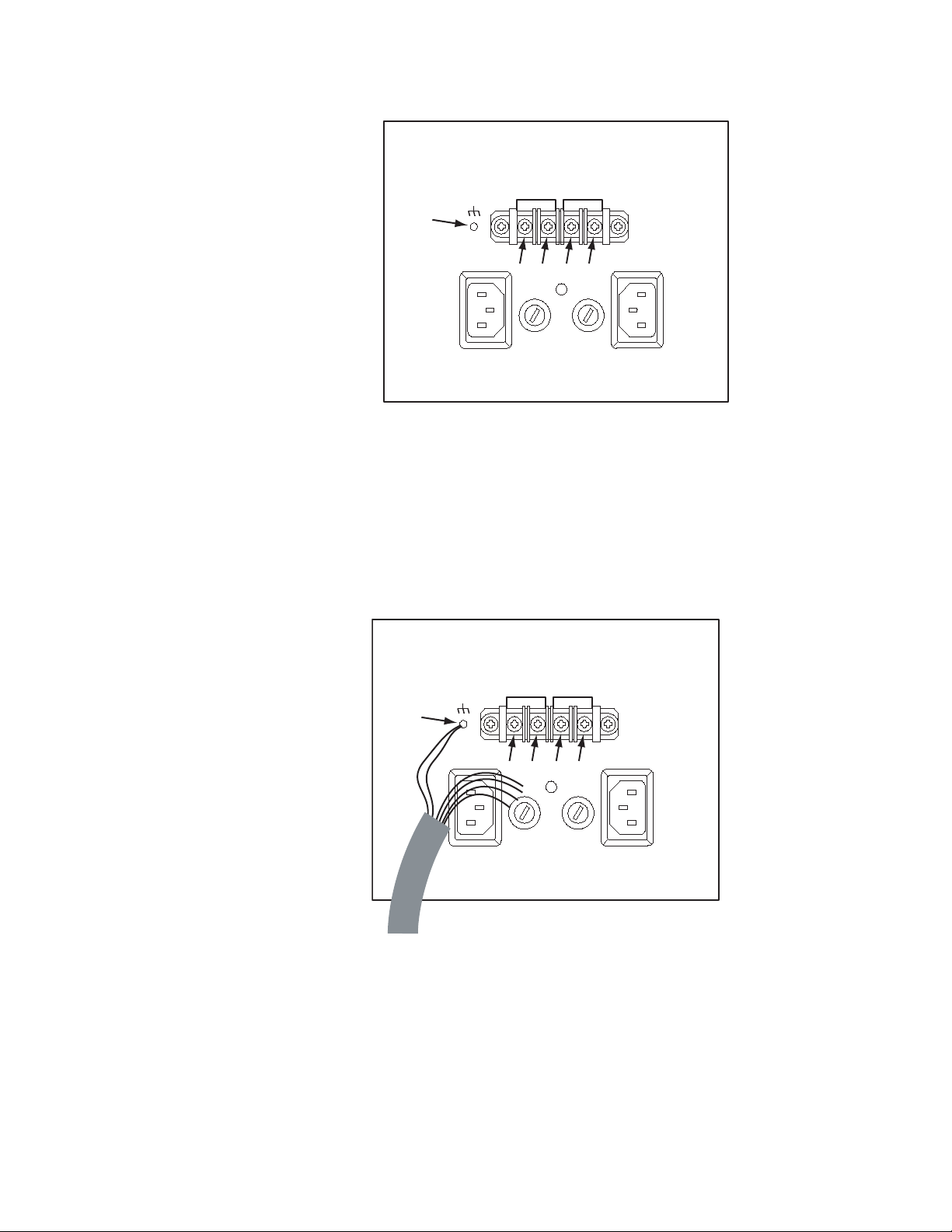
DC IN -DC IN +
PS B PS A
(1)
(2) (3) (4) (5)
8443 07
DC IN -DC IN +
PS B PS A
(1)
(2) (3) (4) (5)
Figure 2. Power Connections Showing Reference Numbers Used for this Document
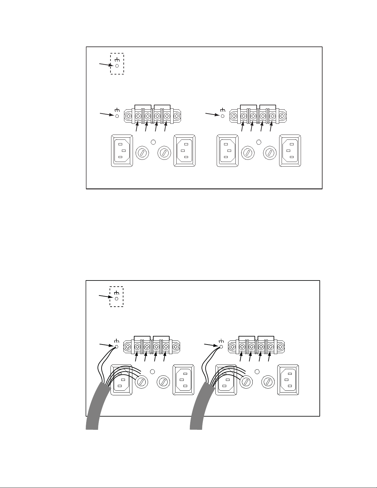
c. Remove the “DC IN +” and “DC IN -” screws (2), (3), (4), and (5).
d. Locate the DC power ground stud (1). Use a nut driver to remove
one nut (only) and one washer (only) from the stud.
e. Connect the supplied external power supply cables as shown in
Figure 3 and Table 1.
Figure 3. DV-33128/256 External Power Supply Wiring (Partially Complete)
44 Trinix — Installation and Service Manual
Page 45

Installation Procedure - DV-33128 and DV-33256 Units
Table 1. External Power Supply Wiring (Complete)
Wire Color
Yellow/green (1)
Black (1)
Red (2)
Blue (3)
White (4)
Yel low (5 )
f. All connections to the router itself are now done. Double check all
Connect to
Terminal
wiring.
3. Connect the AC or DC power cords to the external power supplies.
4. At the front of the external power supply chassis, screw in each supply.
Verify that the two LEDs on the front of each supply are green (AC
good/DC good), and that the fans all rotate.
5. Restore power to the Trinix internal power supplies.
6. Check the DC voltage now being provided at the Trinix “DC In”
connectors. Voltage should be between 47 and 48.5 VDC. If not, contact
Grass Valley Technical Support.
7. Check the fail-over function of the new supply(s).This procedure
should not cause any interruption to router operation. However, Grass
Valley recommends that you perform this check when the
consequences of possible signal interruption are at a minimum.
a. Pull the internal power supplies out a few inches. The router should
remain powered up. Push the internal supplies back into position.
8. In some cases, the original Trinix system may have been supplied with
a total of only one internal power supply. In this case, the SR/NR33000’s sync card jumper JN2 must be moved to the “AC” position for
the alarm system to operate properly.
Note For more information about this jumper, refer to the redundant power supply
notes in the Installation section of the Trinix manual.
This completes the installation.
Trinix — Installation and Service Manual 45
Page 46

Section 3 — Installation for Legacy Frames
DC INPUT
DC IN -DC IN +
42 - 54 VDC
30-24 AMPS
PS B PS A
DC INPUT
DC IN -DC IN +
42 - 54 VDC
30-24 AMPS
PS D PS C
289 - 320
INPUTS
449 - 480
OUTPUTS
161 - 192
OUTPUTS
353 - 384
B
A
B
A
B
A
B
1
4
3
2
MON
OP
A
INPUTS
129 - 160
OUTPUTSINPUTS
417 - 448
OUTPUTS
225 - 256
INPUTS
193 - 224
INPUTSINPUTS
385 - 416
OUTPUTS
289 - 320
OUTPUTS
321 - 352
OUTPUTS
481 - 512
OUTPUTS
257 - 288
OUTPUTS
DC IN + DC IN -
30 - 24 AMPS
DC IN +
30 - 24 AMPS
DC IN -
42 - 54 VDC
DC INPUT 2 NOT FUSED
DC INPUT 1 NOT FUSED
42 - 54 VDC
1
2
4
3
IN
REF
INPUTS
353 - 384
INPUTS
321 - 352
INPUTS
257 - 288
INPUTS
1024
512
2048
1536
16
112
1
15
80
48
64
80
48
64
0
ULTRA
MONITOR
16
32
96
112
3
5
4
12
11
13
3
6
5
2
4
8
14
13
12
11
10
8
0
7
1
9
15
FRAME
610
79
LEVEL
32
SUPER
0
96
2
0
14
C
B
A
INT XPT CNTL
OUTPUT EXPAND
INPUT EXPAND
60Hz ENABLE
SYNC REDUNDANT
PS IFC FAN IFC
XPT BUS
COM BUSCOM BUS
ALARM
CONTROL
CONSOLE B
CONSOLE A
AGAINST RISK OF FIRE, REPLACE ONLY
WITH SAME TYPE AND RATING OF FUSE
WARNING: FOR CONTINUED PROTECTION
AC INPUT: 100-240 V ~, 10.0-5.0A, 50-60Hz
PS D
DC IN -DC IN +
100-120V: 12.5A, 250V, SLO BLO
200-240V: T6.3A, 250V
30 - 24 AMPS
42 - 54 VDC
DC INPUT 2
30 - 24 AMPS
42 - 54 VDC
DC OUT -DC OUT +
DC OUTPUT 2
AC INPUT: 100-240 V ~, 10.0-5.0A, 50-60Hz
100-120V: 12.5A, 250V, SLO BLO
200-240V: T6.3A, 250V
FRAME IFC
NIC B
NIC A
COM BUS
COM BUS
XPT BUS
SECONDARY
PRIMARY
DC IN -DC IN +
30 - 24 AMPS
42 - 54 VDC
DC INPUT 1
42 - 54 VDC
30 - 24 AMPS
DC OUT + DC OUT -
DC OUTPUT 1
PS C PS A
3
1
PS B
GPIO/TC
REF IN
4
REF IN
2
L
E
N
L
E
N
L
E
N
L
E
N
DV-33512
Figure 4. Location of DV-33512 Power Supply Connections
46 Trinix — Installation and Service Manual
Page 47

Installation Procedure - DV-33512 Units
Installation Procedure - DV-33512 Units
Note It is critical that the ORing diodes are present on the 512 PS frame. See the
Note in the Equipment Required section.
1. 1R power supply frames:
a. Install the external power supply frames in a suitable 19-inch
equipment rack.
The frames are shipped with the DC cables already connected.
The power supply frames should be mounted in the same equip-
ment rack as the Trinix, but they may be mounted in an adjacent
rack if necessary. The cables provided for connection to the Trinix
are approximately ten feet (3 m) long.
No special ventilation spacing is needed for these frames since the
airflow is from front to back.
b. Test the external supplies prior to connecting to the Trinix router.
Temporarily apply electrical tape each of the DC output connectors
(red, blue, white, yellow) to isolate them to prevent shorting out.
Apply power to the external power supplies.
c. Using a voltmeter, verify that the external frame’s output voltage
measures between 47 and 48.5 VDC. Contact Grass Valley
Technical Support if the output voltage is not between this range.
d. Unplug each of the external power supplies’ AC power cords.
e. Unscrew each of the external power supply’s restraining screw and
slide each supply out of the chassis 1 inch.
CAUTION The following steps will interrupt all signals passing though the router until
power is restored.
2. Proceed as follows:
a. Power down the router by unplugging the AC cord for each of the
internal power supplies.
b. On the rear of the Trinix PS chassis, locate the “DC IN +” and “DC
IN -” terminal blocks. See Figure 5.
Note The (1) reference is an extra ground check point. Currently it is not being
used.
Trinix — Installation and Service Manual 47
Page 48
Section 3 — Installation for Legacy Frames
DC IN -DC IN +
PS B PS A
DC IN -DC IN +
PS D PS C
(1)
(2) (7)
(3) (4) (5) (6) (8) (9) (10) (11)
DC IN -DC IN +
PS B PS A
DC IN -DC IN +
PS D PS C
(1)
(2) (7)
(3) (4) (5) (6) (8) (9) (10) (11)
to external A/B power supply(s)to external C/D power supply(s)
Figure 5. DV-33512 Power Supply Connectors Showing Reference Numbers Used in this Document
c. Remove the “DC IN +” and “DC IN -” screws (3), (4), (5), (6), (8), (9),
(10), and (11).
d. Locate the two DC power ground studs (2) and (7). Use a nut driver
to remove one nut (only) and one washer (only) from each stud.
e. Connect the supplied jumper wires and external power supply
cables as shown in Figure 6 and Table 2.
Figure 6. Jumper and External Power Supply Wiring (Partially Complete)
48 Trinix — Installation and Service Manual
Page 49

Installation Procedure - DV-33512 Units
Table 2. Jumper and Power Cable Wiring (Complete)
Terminal Power Cable
(2) C/D yellow/green
(3) C/D red
(4) C/D blue
(5) C/D white
(6) C/D yellow
(7) A/B yellow/green
(8) A/B red
(9) A/B blue
(10) A/B white
(11) A/B yellow
C/D black
A/B black
f. All connections to the router itself are now done. Double check all
wiring.
3. Connect the AC power cords for the external A/B power supplies and
the external C/D power supplies.
4. At the front of the external power supplies chassis, screw in each
external supply. Verify that the two LEDs on the front of each supply are
green (AC good/DC good), and that the fans all rotate.
5. Restore power to the internal power supplies.
6. Check the DC voltage now being provided at the Trinix “DC In”
connector(s). Voltage should be between 47 and 48.5 VDC. If not,
contact Technical Support.
7. At an appropriate time, check the fail-over function of the new
supplies. This procedure should not cause any interruption to router
operation. However, Grass Valley recommends that you perform this
check when the consequences of possible signal interruption are at a
minimum.
•First make sure that both external power supply frames are
installed and powered on per the above procedure. Open the main
chassis door. Open the Trinix power supply chassis and pull the A
and B supplies out a few inches. The router should remain powered
up. Replace the A and B supplies. Pull the C and D supplies; the
router should remain powered. Replace the C and D supplies.
8. In some cases, the original system may have been supplied with a total
of only two internal power supplies. In this case, the RP-33500 512 x 512
Rear Panel’s card jumper JN1 must now be moved to the “AC”
position. This step ensures that the alarm system will operate properly.
Trinix — Installation and Service Manual 49
Page 50

Section 3 — Installation for Legacy Frames
Note For more information about this jumper, refer to the redundant power supply
notes in the Installation section of the Trinix manual.
This completes the installation.
50 Trinix — Installation and Service Manual
Page 51

Specifications
Mechanical
Table 1. Mechanical Specifications
Depth
TRX-PS-BU1200 11.56 in. / 294 mm 19.0 in. / 483 mm 1.75 in. / 44 mm 7.2 lb. / 3.2 kg 1
TRX-PS-BU2400 11.56 in. / 294 mm 19.0 in. / 483 mm 1.75 in. / 44 mm 10.3 lb. / 4.6 kg 1
a
Allow a minimum of 6 in. (152 mm) of clear space at the rear of the MCP for proper cable clearance and air flow.
b
All weights approximate.
Environmental
Appendix 4
, a
Width Height Weight
b
Rack Units
Table 2.
Environmental Characteristics (operation with required forced air cooling)
Operating temperature 32 to 104 degrees F (0 to 40 degrees C) ambient
Full specifications met 32 to 104 degrees F (0 to 40 degrees C)
Storage temperature -40 to 185 F (-40 to +85 degrees C)
Air Intake/Exhaust Locations
All modules draw cooling air through fans in the front. Warm air is
exhausted through openings in the back. It is not necessary to leave open
space above or below the chassis.
Trinix — Installation and Service Manual 51
Page 52

Appendix 4 — Specifications
Electrical
Table 3.
Output Power 1200 watts per module
Input voltage range 100 - 240 VAC
Input frequency 47 - 63 Hz
Hot-swap operation Yes
52 Trinix — Installation and Service Manual
 Loading...