

Page 1

Trinix
DIGITAL VIDEO ROUTER
Planning and Installation Manual
SOFTWARE VERSION 2.4.1
071827607
August 4, 2007
Page 2

Affiliate with the N.V. KEMA in The Netherlands
A
CERTIFICATE
Certificate Number: 510040.001
The Quality System of:
Grass Valley, Inc.
400 Providence Mine Road
Nevada City, CA 95945
United States
15655 SW Greystone Ct.
Beaverton, OR 97006
United States
10 Presidential Way
rd
Floor, Suite 300
3
Woburn, MA 01801
United States
Nederland B.V.
4800 RP BREDA
The Netherlands
Technopole Brest Iroise
CS 73808
29238 Brest Cedex 3
France
7140 Baymeadows Way
Suite 101
Jacksonville, FL 32256
United States
Weiterstadt, Germany
Brunnenweg 9
D-64331 Weiterstadt
Germany
17 rue du Petit Albi-BP 8244
95801 Cergy Pontoise
Cergy, France
Rennes, France
Rue du Clos Courtel
Cesson-Sevigne, Cedex
France
2300 South Decker Lake Blvd.
Salt Lake City, UT 84119
United States
Including its implementation, meets the requirements of the standard:
ISO 9001:2000
Scope:
The design, manufacture and support of video hardware and software products and
related systems.
This Certificate is valid until: June 14, 2009
This Certificate is valid as of: August 30, 2006
Certified for the first time: June 14, 2000
H. Pierre Sallé
President
KEMA-Registered Quality
The method of operation for quality certification is defined in the KEMA General Terms
And Conditions For Quality And Environmental Management Systems Certifications.
Integral publication of this certificate is allowed.
KEMA-Registered Quality, Inc.
4377 County Line Road
Chalfont, PA 18914
Ph: (215)997-4519
Fax: (215)997-3809
CRT 001 073004
ccredited By:
ANAB
Page 3
Trinix
DIGITAL VIDEO ROUTER
Planning and Installation Manual
SOFTWARE VERSION 2.4.1
071827607
August 4, 2007
Page 4

Contacting Grass Valley
International
Support Centers
Local Support
Centers
(available
during normal
business hours)
France
24 x 7
Australia and New Zealand: +61 1300 721 495 Central/South America: +55 11 5509 3443
Middle East: +971 4 299 64 40 Near East and Africa: +800 8080 2020 or +33 1 48 25 20 20
Europe
+800 8080 2020 or +33 1 48 25 20 20
+800 8080 2020 or +33 1 48 25 20 20
Hong Kong, Taiwan, Korea, Macau: +852 2531 3058 Indian Subcontinent: +91 22 24933476
Asia
Southeast Asia/Malaysia: +603 7805 3884 Southeast Asia/Singapore: +65 6379 1313
China: +861 0660 159 450 Japan: +81 3 5484 6868
Belarus, Russia, Tadzikistan, Ukraine, Uzbekistan: +7 095 2580924 225 Switzerland: +41 1 487 80 02
S. Europe/Italy-Roma: +39 06 87 20 35 28 -Milan: +390248414658 S. Europe/Spain: +34 91 512 03 50
Benelux/Belgium: +32 (0) 2 334 90 30 Benelux/Netherlands: +31 (0) 35 62 38 42 1 N. Europe: +4545968870
Germany, Austria, Eastern Europe: +49 6150 104 444 UK, Ireland, Israel: +44 118 923 0499
Copyright © Grass Valley, Inc. All rights reserved. All specifications subject to change without notice.
This product may be covered by one or more U.S. and foreign patents.
United States/Canada
24 x 7
+1 800 547 8949 or +1 530 478 4148
Grass Valley Web Site
The www.thomsongrassvalley.com web site offers the following:
Online User Documentation — Current versions of product catalogs, brochures,
data sheets, ordering guides, planning guides, manuals, and release notes
in .pdf format can be downloaded.
FAQ Database — Solutions to problems and troubleshooting efforts can be
found by searching our Frequently Asked Questions (FAQ) database.
4 Trinix Planning and Installation Manual
Page 5

Contents
Preface. . . . . . . . . . . . . . . . . . . . . . . . . . . . . . . . . . . . . . . . . . . . . . . . . . . . . . . . . . . . . . . . . . . . . 9
Safety Summary
Regulatory Notices
About This Manual. . . . . . . . . . . . . . . . . . . . . . . . . . . . . . . . . . . . . . . . . . . . . . . . . . . . . 9
Additional Documentation . . . . . . . . . . . . . . . . . . . . . . . . . . . . . . . . . . . . . . . . . . . . 9
Safety Terms and Symbols. . . . . . . . . . . . . . . . . . . . . . . . . . . . . . . . . . . . . . . . . . . . . . 11
Terms in This Manual. . . . . . . . . . . . . . . . . . . . . . . . . . . . . . . . . . . . . . . . . . . . . . . . 11
Terms on the Product . . . . . . . . . . . . . . . . . . . . . . . . . . . . . . . . . . . . . . . . . . . . . . . . 11
Symbols on the Product . . . . . . . . . . . . . . . . . . . . . . . . . . . . . . . . . . . . . . . . . . . . . . 12
Warnings . . . . . . . . . . . . . . . . . . . . . . . . . . . . . . . . . . . . . . . . . . . . . . . . . . . . . . . . . . . . 12
Cautions . . . . . . . . . . . . . . . . . . . . . . . . . . . . . . . . . . . . . . . . . . . . . . . . . . . . . . . . . . . . . 13
Certifications and Compliances . . . . . . . . . . . . . . . . . . . . . . . . . . . . . . . . . . . . . . . . . 15
FCC Emission Control . . . . . . . . . . . . . . . . . . . . . . . . . . . . . . . . . . . . . . . . . . . . . . . 15
Canadian EMC Notice of Compliance . . . . . . . . . . . . . . . . . . . . . . . . . . . . . . . . . . 15
EN 55103 Class A Warning . . . . . . . . . . . . . . . . . . . . . . . . . . . . . . . . . . . . . . . . . . . 15
Canadian Certified Power Cords . . . . . . . . . . . . . . . . . . . . . . . . . . . . . . . . . . . . . . 16
Canadian Certified AC Adapter . . . . . . . . . . . . . . . . . . . . . . . . . . . . . . . . . . . . . . . 16
Laser Compliance . . . . . . . . . . . . . . . . . . . . . . . . . . . . . . . . . . . . . . . . . . . . . . . . . . . 16
Laser Safety Requirements . . . . . . . . . . . . . . . . . . . . . . . . . . . . . . . . . . . . . . . . . . 16
Laser Safety. . . . . . . . . . . . . . . . . . . . . . . . . . . . . . . . . . . . . . . . . . . . . . . . . . . . . . . 16
FCC Emission Limits. . . . . . . . . . . . . . . . . . . . . . . . . . . . . . . . . . . . . . . . . . . . . . . 17
Certification . . . . . . . . . . . . . . . . . . . . . . . . . . . . . . . . . . . . . . . . . . . . . . . . . . . . . . . . 17
Section 1 — Introduction . . . . . . . . . . . . . . . . . . . . . . . . . . . . . . . . . . . . . . . . . . . . . . . . 19
General . . . . . . . . . . . . . . . . . . . . . . . . . . . . . . . . . . . . . . . . . . . . . . . . . . . . . . . . . . . . 19
SD and HD in the Same Frame . . . . . . . . . . . . . . . . . . . . . . . . . . . . . . . . . . . . . . . . 20
Easy to Create Very Large Routers . . . . . . . . . . . . . . . . . . . . . . . . . . . . . . . . . . . . . 20
Control Systems. . . . . . . . . . . . . . . . . . . . . . . . . . . . . . . . . . . . . . . . . . . . . . . . . . . . . 20
The Trinix Frame . . . . . . . . . . . . . . . . . . . . . . . . . . . . . . . . . . . . . . . . . . . . . . . . . . . . 20
Trinix Architecture . . . . . . . . . . . . . . . . . . . . . . . . . . . . . . . . . . . . . . . . . . . . . . . . . . 21
Serviceability and Reliability . . . . . . . . . . . . . . . . . . . . . . . . . . . . . . . . . . . . . . . . . . 21
Broadlinx. . . . . . . . . . . . . . . . . . . . . . . . . . . . . . . . . . . . . . . . . . . . . . . . . . . . . . . . . . . 22
Broadlinx Web Page Monitoring . . . . . . . . . . . . . . . . . . . . . . . . . . . . . . . . . . . . . 23
SNMP/NetCentral Monitoring . . . . . . . . . . . . . . . . . . . . . . . . . . . . . . . . . . . . . . 23
Section 2 — Planning Guide . . . . . . . . . . . . . . . . . . . . . . . . . . . . . . . . . . . . . . . . . . . . 27
Introduction . . . . . . . . . . . . . . . . . . . . . . . . . . . . . . . . . . . . . . . . . . . . . . . . . . . . . . . . . . 27
Trinix Frame. . . . . . . . . . . . . . . . . . . . . . . . . . . . . . . . . . . . . . . . . . . . . . . . . . . . . . . . . . 27
Power Supplies. . . . . . . . . . . . . . . . . . . . . . . . . . . . . . . . . . . . . . . . . . . . . . . . . . . . 35
Cooling System. . . . . . . . . . . . . . . . . . . . . . . . . . . . . . . . . . . . . . . . . . . . . . . . . . . . 36
Sync Reference Options . . . . . . . . . . . . . . . . . . . . . . . . . . . . . . . . . . . . . . . . . . . . 38
Output Monitoring . . . . . . . . . . . . . . . . . . . . . . . . . . . . . . . . . . . . . . . . . . . . . . . . 38
Signal Flow . . . . . . . . . . . . . . . . . . . . . . . . . . . . . . . . . . . . . . . . . . . . . . . . . . . . . . . 39
Analog Processing Control. . . . . . . . . . . . . . . . . . . . . . . . . . . . . . . . . . . . . . . . . . 40
Pre-wiring . . . . . . . . . . . . . . . . . . . . . . . . . . . . . . . . . . . . . . . . . . . . . . . . . . . . . . . . 40
Trinix Planning and Installation Manual 5
Page 6

Contents
Connector Numbering . . . . . . . . . . . . . . . . . . . . . . . . . . . . . . . . . . . . . . . . . . . . . 40
Alarm System. . . . . . . . . . . . . . . . . . . . . . . . . . . . . . . . . . . . . . . . . . . . . . . . . . . . . 41
Duplication and Expansion. . . . . . . . . . . . . . . . . . . . . . . . . . . . . . . . . . . . . . . . . . . . . 43
Output Duplication - Dual . . . . . . . . . . . . . . . . . . . . . . . . . . . . . . . . . . . . . . . . . . . 43
Output Duplication - Quad . . . . . . . . . . . . . . . . . . . . . . . . . . . . . . . . . . . . . . . . . . . 48
Expanded Systems . . . . . . . . . . . . . . . . . . . . . . . . . . . . . . . . . . . . . . . . . . . . . . . . . . 50
Termination for Pre-wired Expansion Frames . . . . . . . . . . . . . . . . . . . . . . . . . 56
Monitoring with Expanded Systems . . . . . . . . . . . . . . . . . . . . . . . . . . . . . . . . . 59
Protected Paths . . . . . . . . . . . . . . . . . . . . . . . . . . . . . . . . . . . . . . . . . . . . . . . . . . . . . . . 60
Overview . . . . . . . . . . . . . . . . . . . . . . . . . . . . . . . . . . . . . . . . . . . . . . . . . . . . . . . . . . 60
Planning . . . . . . . . . . . . . . . . . . . . . . . . . . . . . . . . . . . . . . . . . . . . . . . . . . . . . . . . . . . 62
Worksheet for Protected Path Implementation . . . . . . . . . . . . . . . . . . . . . . . . 69
Control Systems . . . . . . . . . . . . . . . . . . . . . . . . . . . . . . . . . . . . . . . . . . . . . . . . . . . . . . 70
Jupiter Facility Control System. . . . . . . . . . . . . . . . . . . . . . . . . . . . . . . . . . . . . . . . 70
SMS 7000 / Encore Control . . . . . . . . . . . . . . . . . . . . . . . . . . . . . . . . . . . . . . . . . . . 72
LAN and Com Bus Connections . . . . . . . . . . . . . . . . . . . . . . . . . . . . . . . . . . . . . . . . 73
Com Bus . . . . . . . . . . . . . . . . . . . . . . . . . . . . . . . . . . . . . . . . . . . . . . . . . . . . . . . . . 76
System Monitoring Applications . . . . . . . . . . . . . . . . . . . . . . . . . . . . . . . . . . . . . . . . 77
Specifications. . . . . . . . . . . . . . . . . . . . . . . . . . . . . . . . . . . . . . . . . . . . . . . . . . . . . . . . . 78
Electrical . . . . . . . . . . . . . . . . . . . . . . . . . . . . . . . . . . . . . . . . . . . . . . . . . . . . . . . . . . . 78
Environmental. . . . . . . . . . . . . . . . . . . . . . . . . . . . . . . . . . . . . . . . . . . . . . . . . . . . . . 80
Physical. . . . . . . . . . . . . . . . . . . . . . . . . . . . . . . . . . . . . . . . . . . . . . . . . . . . . . . . . . . . 80
Configuration . . . . . . . . . . . . . . . . . . . . . . . . . . . . . . . . . . . . . . . . . . . . . . . . . . . . . . . . 81
Quick Look . . . . . . . . . . . . . . . . . . . . . . . . . . . . . . . . . . . . . . . . . . . . . . . . . . . . . . . 81
Chassis, Board, Weight and Power Summary for Select Matrix Sizes . . . . . 81
Ordering Information . . . . . . . . . . . . . . . . . . . . . . . . . . . . . . . . . . . . . . . . . . . . . . . . . 83
Frames . . . . . . . . . . . . . . . . . . . . . . . . . . . . . . . . . . . . . . . . . . . . . . . . . . . . . . . . . . . . 83
Input, Output, and Matrix Boards . . . . . . . . . . . . . . . . . . . . . . . . . . . . . . . . . . . . . 83
Options . . . . . . . . . . . . . . . . . . . . . . . . . . . . . . . . . . . . . . . . . . . . . . . . . . . . . . . . . . . . 85
Additional video signal cards . . . . . . . . . . . . . . . . . . . . . . . . . . . . . . . . . . . . . . . 85
Power Supplies and Fans . . . . . . . . . . . . . . . . . . . . . . . . . . . . . . . . . . . . . . . . . . . 85
NIC/Sync/OPM Boards . . . . . . . . . . . . . . . . . . . . . . . . . . . . . . . . . . . . . . . . . . . 86
Port Expanders . . . . . . . . . . . . . . . . . . . . . . . . . . . . . . . . . . . . . . . . . . . . . . . . . . . 87
SNMP/NetCentral Software Options . . . . . . . . . . . . . . . . . . . . . . . . . . . . . . . . 88
Miscellaneous. . . . . . . . . . . . . . . . . . . . . . . . . . . . . . . . . . . . . . . . . . . . . . . . . . . . . 88
Section 3 — Installation . . . . . . . . . . . . . . . . . . . . . . . . . . . . . . . . . . . . . . . . . . . . . . . . 91
Summary of Installation Procedure. . . . . . . . . . . . . . . . . . . . . . . . . . . . . . . . . . . . . . 91
Rear Panel Dip Switch Settings . . . . . . . . . . . . . . . . . . . . . . . . . . . . . . . . . . . . . . . . 103
Miscellaneous rear panel connectors . . . . . . . . . . . . . . . . . . . . . . . . . . . . . . . . 104
Power Supply Notes . . . . . . . . . . . . . . . . . . . . . . . . . . . . . . . . . . . . . . . . . . . . . . . . . 104
DV-33128 and DV-33256 Chassis Installations . . . . . . . . . . . . . . . . . . . . . . . . 104
DV-33512 Chassis Installation. . . . . . . . . . . . . . . . . . . . . . . . . . . . . . . . . . . . . . 105
Sync Reference Connections . . . . . . . . . . . . . . . . . . . . . . . . . . . . . . . . . . . . . . . . . . . 107
NR/SR-33000 / SR-33500 V-Phasing. . . . . . . . . . . . . . . . . . . . . . . . . . . . . . . . . . . . 117
Output Board Configuration . . . . . . . . . . . . . . . . . . . . . . . . . . . . . . . . . . . . . . . . . . 123
Duplication and Expansion. . . . . . . . . . . . . . . . . . . . . . . . . . . . . . . . . . . . . . . . . . . . 124
Output Duplication. . . . . . . . . . . . . . . . . . . . . . . . . . . . . . . . . . . . . . . . . . . . . . . 124
Input Expansion . . . . . . . . . . . . . . . . . . . . . . . . . . . . . . . . . . . . . . . . . . . . . . . . . 126
Output Expansion . . . . . . . . . . . . . . . . . . . . . . . . . . . . . . . . . . . . . . . . . . . . . . . . 130
Output Reclocker Bypass Settings . . . . . . . . . . . . . . . . . . . . . . . . . . . . . . . . . . . . . . 134
Sync Selection Switch S5 . . . . . . . . . . . . . . . . . . . . . . . . . . . . . . . . . . . . . . . . . . 135
Input Equalization Settings (DV-33512 Models Only) . . . . . . . . . . . . . . . . . . . . . 136
6 Trinix Planning and Installation Manual
Page 7

Output Monitoring . . . . . . . . . . . . . . . . . . . . . . . . . . . . . . . . . . . . . . . . . . . . . . . . . . . 137
Setting the Output Monitor Address . . . . . . . . . . . . . . . . . . . . . . . . . . . . . . . . 141
Output Monitor Reclock / Force Bypass Settings. . . . . . . . . . . . . . . . . . . . . . 142
Monitoring with Expanded Systems. . . . . . . . . . . . . . . . . . . . . . . . . . . . . . . . . 144
Frame Number Settings . . . . . . . . . . . . . . . . . . . . . . . . . . . . . . . . . . . . . . . . . . . . . . . 146
Setting the Chassis for Input/output Blocks . . . . . . . . . . . . . . . . . . . . . . . . . . 146
Jupiter Control. . . . . . . . . . . . . . . . . . . . . . . . . . . . . . . . . . . . . . . . . . . . . . . . . . . . . . . 148
SMS 7000 / Encore Control . . . . . . . . . . . . . . . . . . . . . . . . . . . . . . . . . . . . . . . . . . . . 153
LAN and Com Bus Connections. . . . . . . . . . . . . . . . . . . . . . . . . . . . . . . . . . . . . . . . 155
Com Bus . . . . . . . . . . . . . . . . . . . . . . . . . . . . . . . . . . . . . . . . . . . . . . . . . . . . . . . . 158
NR-33000 (Broadlinx) Board Configuration . . . . . . . . . . . . . . . . . . . . . . . . . . 159
Section 4 — Broadlinx. . . . . . . . . . . . . . . . . . . . . . . . . . . . . . . . . . . . . . . . . . . . . . . . . . 161
Network Configuration . . . . . . . . . . . . . . . . . . . . . . . . . . . . . . . . . . . . . . . . . . . . . 161
Simple Network . . . . . . . . . . . . . . . . . . . . . . . . . . . . . . . . . . . . . . . . . . . . . . . . . . 161
Complex Network . . . . . . . . . . . . . . . . . . . . . . . . . . . . . . . . . . . . . . . . . . . . . . . . 163
Software Installation . . . . . . . . . . . . . . . . . . . . . . . . . . . . . . . . . . . . . . . . . . . . . . . . 166
SNMP/NetCentral Monitoring . . . . . . . . . . . . . . . . . . . . . . . . . . . . . . . . . . . . . . . 166
Broadlinx / Internet Explorer Monitoring. . . . . . . . . . . . . . . . . . . . . . . . . . . . . . 166
Firmware Update. . . . . . . . . . . . . . . . . . . . . . . . . . . . . . . . . . . . . . . . . . . . . . . . . . . 177
On-line Help. . . . . . . . . . . . . . . . . . . . . . . . . . . . . . . . . . . . . . . . . . . . . . . . . . . . . . . 177
Contents
Section 5 — Protected Path Configuration. . . . . . . . . . . . . . . . . . . . . . . . . . . . 179
System Configuration. . . . . . . . . . . . . . . . . . . . . . . . . . . . . . . . . . . . . . . . . . . . . . . . . 179
Encore Configuration . . . . . . . . . . . . . . . . . . . . . . . . . . . . . . . . . . . . . . . . . . . . . . . . . 184
Jupiter Configuration . . . . . . . . . . . . . . . . . . . . . . . . . . . . . . . . . . . . . . . . . . . . . . . . . 189
Operation Notes . . . . . . . . . . . . . . . . . . . . . . . . . . . . . . . . . . . . . . . . . . . . . . . . . . . . . 191
Section 6 — Analog Input Processing. . . . . . . . . . . . . . . . . . . . . . . . . . . . . . . . . 193
TRX-VI-33100 Module . . . . . . . . . . . . . . . . . . . . . . . . . . . . . . . . . . . . . . . . . . . . . . . . 193
Analog Processing Control . . . . . . . . . . . . . . . . . . . . . . . . . . . . . . . . . . . . . . . . . . 193
Customizing Analog Video Processing Settings. . . . . . . . . . . . . . . . . . . . . . . . . 194
Terminal Setup . . . . . . . . . . . . . . . . . . . . . . . . . . . . . . . . . . . . . . . . . . . . . . . . . . . 194
Main Menu Options. . . . . . . . . . . . . . . . . . . . . . . . . . . . . . . . . . . . . . . . . . . . . . . 198
Section 7 — Troubleshooting . . . . . . . . . . . . . . . . . . . . . . . . . . . . . . . . . . . . . . . . . . 211
LEDs. . . . . . . . . . . . . . . . . . . . . . . . . . . . . . . . . . . . . . . . . . . . . . . . . . . . . . . . . . . . 211
Signal flow . . . . . . . . . . . . . . . . . . . . . . . . . . . . . . . . . . . . . . . . . . . . . . . . . . . . . . 218
Section A — SNMP Managers . . . . . . . . . . . . . . . . . . . . . . . . . . . . . . . . . . . . . . . . . 221
Adding SNMP Managers. . . . . . . . . . . . . . . . . . . . . . . . . . . . . . . . . . . . . . . . . . . . . . 221
Deleting SNMP Managers . . . . . . . . . . . . . . . . . . . . . . . . . . . . . . . . . . . . . . . . . . . . . 222
Glossary . . . . . . . . . . . . . . . . . . . . . . . . . . . . . . . . . . . . . . . . . . . . . . . . . . . . . . . . . . . . . . . . . 223
Index . . . . . . . . . . . . . . . . . . . . . . . . . . . . . . . . . . . . . . . . . . . . . . . . . . . . . . . . . . . . . . . . . . . . . 227
Trinix Planning and Installation Manual 7
Page 8

Contents
8 Trinix Planning and Installation Manual
Page 9

Preface
About This Manual
This manual provides system planning, installation and troubleshooting
information specific to the Trinix Digital Video Router.
The Trinix Digital Video Router can be controlled by the Grass Valley
Jupiter or Encore Control System. Configuration information for the
control system itself is contained in the control system’s documentation set:
Jupiter Control System Release Notes series, 0718275xx.
Jupiter VM-3000 Installation and Operating Manual, 0718305xx.
Jupiter CM-4000 Installation and Operating Manual, 0718261xx.
Jupiter Getting Started Guide, 04-045707-003.
Encore Control System Release Notes series, 0718153xx.
Encore Installation and Service Manual, 0718103xx.
Encore Control System User Manual, 0718104xx.
Encore Control Panels Manual, 0718053xx
An electronic copy of the documentation set is normally provided with the
system on CD-ROM 0718130xx. The CD Includes SMS7000 Series Control
System, Acappella, Concerto, Encore, Jupiter, JEP 100, Prelude, and Trinix
documentation.
Individual printed manuals may be ordered by contacting Technical Support. They are also available on our web site. See page 4.
Additional Documentation
NetCentral IV TV Facility Monitoring System User Guide, 0718338xx.
CD-ROM 071827407 includes legacy Jupiter, Saturn, Triton, and Venus
manuals.
.
Planning and Installation Manual 9
Page 10

Preface
10 Planning and Installation Manual
Page 11

Safety Summary
Read and follow the important safety information below, noting especially
those instructions related to risk of fire, electric shock or injury to persons.
Additional specific warnings not listed here may be found throughout the
manual.
WARNING Any instructions in this manual that require opening the equipment cover
or enclosure are for use by qualified service personnel only. To reduce the
risk of electric shock, do not perform any servicing other than that contained in the operating instructions unless you are qualified to do so.
Safety Terms and Symbols
Terms in This Manual
Safety-related statements may appear in this manual in the following form:
WARNING Warning statements identify conditions or practices that may result in per-
sonal injury or loss of life.
CAUTION Caution statements identify conditions or practices that may result in damage
to equipment or other property, or which may cause equipment crucial to
your business environment to become temporarily non-operational.
Terms on the Product
The following terms may appear on the product:
DANGER — A personal injury hazard is immediately accessible as you read
the marking.
WARNING — A personal injury hazard exists but is not immediately acces-
sible as you read the marking.
CAUTION — A hazard to property, product, and other equipment is present.
Planning and Installation Manual 11
Page 12
Safety Summary
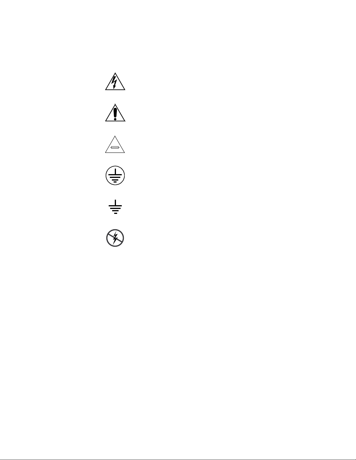
Symbols on the Product
The following symbols may appear on the product:
Indicates that dangerous high voltage is present within the
equipment enclosure that may be of sufficient magnitude to
constitute a risk of electric shock.
Indicates that user, operator or service technician should refer
to product manual(s) for important operating, maintenance,
or service instructions.
This is a prompt to note fuse rating when replacing fuse(s).
The fuse referenced in the text must be replaced with one
having the ratings indicated.
Identifies a protective grounding terminal which must be connected to earth ground prior to making any other equipment
connections.
Warnings
Identifies an external protective grounding terminal which
may be connected to earth ground as a supplement to an
internal grounding terminal.
Indicates that static sensitive components are present which
may be damaged by electrostatic discharge. Use anti-static
procedures, equipment and surfaces during servicing.
The following warning statements identify conditions or practices that can
result in personal injury or loss of life.
Dangerous voltage or current may be present — Disconnect power and remove
battery (if applicable) before removing protective panels, soldering, or
replacing components.
Do not service alone — Do not internally service this product unless another
person capable of rendering first aid and resuscitation is present.
Remove jewelry — Prior to servicing, remove jewelry such as rings, watches,
and other metallic objects.
Avoid exposed circuitry — Do not touch exposed connections, components or
circuitry when power is present.
12 Planning and Installation Manual
Page 13

Safety Summary
Use proper power cord — Use only the power cord supplied or specified for
this product.
Ground product — Connect the grounding conductor of the power cord to
earth ground.
Operate only with covers and enclosure panels in place — Do not operate this
product when covers or enclosure panels are removed.
Use correct fuse — Use only the fuse type and rating specified for this
product.
Use only in dry environment — Do not operate in wet or damp conditions.
Use only in non-explosive environment — Do not operate this product in an
explosive atmosphere.
High leakage current may be present — Earth connection of product is essential
before connecting power.
Dual power supplies may be present — Be certain to plug each power supply
cord into a separate branch circuit employing a separate service ground.
Disconnect both power supply cords prior to servicing.
Cautions
Double pole neutral fusing — Disconnect mains power prior to servicing.
Use proper lift points — Do not use door latches to lift or move equipment.
Avoid mechanical hazards — Allow all rotating devices to come to a stop before
servicing.
The following caution statements identify conditions or practices that can
result in damage to equipment or other property
Use correct power source — Do not operate this product from a power source
that applies more than the voltage specified for the product.
Use correct voltage setting — If this product lacks auto-ranging power sup-
plies, before applying power ensure that the each power supply is set to
match the power source.
Provide proper ventilation — To prevent product overheating, provide equip-
ment ventilation in accordance with installation instructions.
Use anti-static procedures — Static sensitive components are present which
may be damaged by electrostatic discharge. Use anti-static procedures,
equipment and surfaces during servicing.
Planning and Installation Manual 13
Page 14

Safety Summary
Do not operate with suspected equipment failure — If you suspect product
damage or equipment failure, have the equipment inspected by qualified
service personnel.
Ensure mains disconnect — If mains switch is not provided, the power cord(s)
of this equipment provide the means of disconnection. The socket outlet
must be installed near the equipment and must be easily accessible. Verify
that all mains power is disconnected before installing or removing power
supplies and/or options.
Route cable properly — Route power cords and other cables so that they ar not
likely to be damaged. Properly support heavy cable bundles to avoid con-
nector damage.
Use correct power supply cords — Power cords for this equipment, if provided,
meet all North American electrical codes. Operation of this equipment at
voltages exceeding 130 VAC requires power supply cords which comply
with NEMA configurations. International power cords, if provided, have
the approval of the country of use.
Use correct replacement battery — This product may contain batteries. To
reduce the risk of explosion, check polarity and replace only with the same
or equivalent type recommended by manufacturer. Dispose of used bat-
teries according to the manufacturer’s instructions.
Troubleshoot only to board level — Circuit boards in this product are densely
populated with surface mount technology (SMT) components and applica-
tion specific integrated circuits (ASICS). As a result, circuit board repair at
the component level is very difficult in the field, if not impossible. For war-
ranty compliance, do not troubleshoot systems beyond the board level.
14 Planning and Installation Manual
Page 15

Regulatory Notices
Certifications and Compliances
FCC Emission Control
This equipment has been tested and found to comply with the limits for a
Class A digital device, pursuant to Part 15 of the FCC Rules. These limits
are designed to provide reasonable protection against harmful interference
when the equipment is operated in a commercial environment. This equipment generates, uses, and can radiate radio frequency energy and, if not
installed and used in accordance with the instruction manual, may cause
harmful interference to radio communications. Operation of this equipment in a residential area is likely to cause harmful interference in which
case the user will be required to correct the interference at his own expense.
Changes or modifications not expressly approved by Grass Valley Group
can affect emission compliance and could void the user’s authority to
operate this equipment.
Canadian EMC Notice of Compliance
This digital apparatus does not exceed the Class A limits for radio noise
emissions from digital apparatus set out in the Radio Interference Regulations of the Canadian Department of Communications.
Le présent appareil numérique n’emet pas de bruits radioélectriques
dépassant les limites applicables aux appareils numeriques de la classe A
préscrites dans le Règlement sur le brouillage radioélectrique édicte par le
ministère des Communications du Canada.
EN 55103 Class A Warning
For products that comply with Class A. In a domestic environment this
product may cause radio interference in which case the user may be
required to take adequate measures.
Planning and Installation Manual 15
Page 16

Regulatory Notices
Canadian Certified Power Cords
Canadian Certified AC Adapter
Laser Compliance
Laser Safety Requirements
Canadian approval includes the products and power cords appropriate for
use in the North America power network. All other power cords supplied
are approved for the country of use.
Canadian approval includes the AC adapters appropriate for use in the
North America power network. All other AC adapters supplied are
approved for the country of use.
The device used in this product is a Class 1 certified laser product. Oper-
ating this product outside specifications or altering from its original design
may result in hazardous radiation exposure, and may be considered an act
of modifying or new manufacturing of a laser product under U.S. regula-
tions contained in 21CFR Chapter1, subchapter J or CENELEC regulations
in HD 482 S1. People performing such an act are required by law to recertify
and reidentify this product in accordance with provisions of 21CFR sub-
chapter J for distribution within the U.S.A., and in accordance with
CENELEC HD 482 S1 for distribution within countries using the IEC 825
standard.
Laser Safety
Laser safety in the United States is regulated by the Center for Devices and
Radiological Health (CDRH). The laser safety regulations are published in
the “Laser Product Performance Standard,” Code of Federal Regulation
(CFR), Title 21, Subchapter J.
The international Electrotechnical Commission (IEC) Standard 825, “Radi-
ation of Laser Products, Equipment Classification, Requirements and
User’s Guide,” governs laser products outside the United States. Europe
and member nations of the European Free trade Association fall under the
jurisdiction of the Comite European de Normalization Electrotechnique
(CENELEC).
For the CDRH: The radiant power is detected trough a 7 mm aperture at a
distance of 200 mm from the source focused through a lens with a focal
length of 100 mm.
For IEC compliance: The radiant power is detected trough a 7 mm aperture
at a distance of 100 mm from the source focused through a lens with a focal
length of 100 mm.
16 Planning and Installation Manual
Page 17

FCC Emission Limits
Certification
Regulatory Notices
This device complies with Part 15 of the FCC Rules. Operation is subject to
the following two conditions: (1) This device may no cause harmful interference, and (2) this device must accept any interference received,
including interference that may cause undesirable operation. This device
has been tested and found to comply with FCC Part 15 Class B limits for a
digital device when tested with a representative laser-based fiber optical
system that complies with ANSI X3T11 Fiber Channel Standard.
Category Standard Designed/tested for compliance with:
Safety ANSI/UL 1950-1997 3rd Ed.
CAN/CSA-C22.2 No. 950-95
EN 60950
Professional Video and Audio Equipment
Planning and Installation Manual 17
Page 18

Regulatory Notices
18 Planning and Installation Manual
Page 19

Introduction
General
Section 1
The Trinix family of routing switchers represents a revolutionary new
approach to digital
Venus—the best selling routing switcher ever. Trinix is a high-quality
and fully featured digital video routing switcher offering a large
number of crosspoints in one of the smallest physical frames available.
Four fixed frame sizes are available: a 128 x 128 router in eight rack
units, a 128 x 256 router in 12 RUs, a 256 x 256 router in 15 RUs, and a
512 x 512 router in 32 RUs. Fixed frame designs offer optimal solutions
for customers who have minimum space requirements yet still need a
large number of crosspoints. Features of the Trinix routing switcher
architecture include:
• Fourth generation based on Venus
• Standard Definition (SD) and High Definition (HD) in the same
frame
• Easy to upgrade
• High density in minimal space
• Each I/O card supports 32 signals
• Same “crosspoint bus” control as Venus, providing easy integration
with Jupiter Facility Control Systems.
1
signal distribution that builds on the success of
• Mission critical components are front loading and hot swappable
• Extensive alarm notification/status
• Load sharing power supplies
• Redundant fans
• Protected path operation
• Broadlinx option combines network interface, sync input, and
output monitor circuitry; allows LAN-based control by Encore/
SMS and system monitoring via Microsoft Internet Explorer.
SNMP/NetCentral system monitoring also available
• Passive expanders for input/output expansion, dual/quad outputs
• Chassis design maximizes air flow
1.
The new VI-33100 module provides analog as well as digital inputs.
Planning and Installation Manual 19
Page 20

Introduction
SD and HD in the Same Frame
Easy to Create Very Large Routers
Trinix supports both SD and HD video in all configurations. The matrix
cards and high-speed backplane are designed for both SD and HD signals. The only difference between SD and HD implementations is the I/
O cards. This makes upgrading easy on both budgets and implementation, thus solving the problem of deciding when to prepare for HD in a
facility.
Creating very large routers in the Trinix design is accomplished by
using special circuitry for simple and cost effective expansion. Using
passive port expansion modules, a 1024 x 1024 router can be built in
four equipment racks using four 512 x 512 frames coupled together
with expanders. These expanders can also be used to provide dual or
quad non-inverting outputs.
Control Systems
The Jupiter Facility Control System can be used to control the Trinix
router using a crosspoint bus connection (see Glossary) to a VM-3000
System Controller or CM-4000 System Controller. The VM/CM can
receive switching commands from a variety of serial sources, including
Jupiter control panels or an automation computer.
The Trinix can also be controlled using direct Ethernet (“CPL”) integration with a Grass Valley Encore or SMS 7000 control system.
The Trinix Frame
• High-density crosspoints in compact frames
• Fixed matrix sizes can be combined to form larger routers
• Modular design allows for both HD and SD within the same frame
Trinix is optimized for crosspoint density, with reliability and serviceability in mind. Each frame has redundant power supplies, redundant
fans, and a physical topology designed to maximize cooling. Mission
critical modules are front loading and hot swappable.
All Trinix frames accommodate two load-sharing power supplies and
have two AC inputs. This allows for full redundant operations. They
are front loading and hot swappable and each power supply has its
own fan for cooling. The 128 x 128 frame runs on a 600 W power supply,
the 256 x 256 frame runs on a 1250 W power supply, and the 512 x 512
runs on two 1250 W power supplies—all with plenty of power to spare.
20 Planning and Installation Manual
Page 21

The 128 x 128 chassis includes two fan modules; the 256 x 256 chassis
includes three, and the 512 x 512 includes six. Both power supplies and
fan modules are front loading and hot swappable.
Trinix Architecture
The architecture of the Trinix signal flow is organized into three cards:
input card, matrix card, and output card. These are connected to a
passive backplane circuit card. Each input and output card accommodates 32 signals, which allows the routers to be built in increments of 32
as well a mixed population of SD and HD cards in increments of 32.
On switchers with HO-33110 HD and HO-33120 SD/HD output cards,
signal reclocking can be set to “Auto On/Off” or “Off” for each of the
32 outputs. In “Auto On/Off” mode, properly-formed standard data
rate signals will be reclocked but other signals will be bypassed (not
reclocked). “Standard” data rates are listed on page 79.
The new VI-33100 “universal” input board auto-senses and accepts 16
composite analog SD, digital SD, or digital HD signals in any combination and passes them in digital SD or digital HD form (as appropriate)
to the Trinix matrix board. When analog signals are received, an extensive set of gain, phase, filtering, and other adjustments are available for
each signal. For a list of these adjustments, see page 40.
The BL-33000 Broadlinx option combines network interface, sync input,
and output monitor circuitry. Each card has two sync inputs and two
monitor outputs. Two cards can be installed for a total of four ports for
each. The sync reference supports generation of Vertical Interval Switch
Timing strobe from standard NTSC or PAL Black Burst or HDTV Trilevel sync defined in the SMPTE 274M-1998 standard (see Glossary).
Sync reference granularity is 32 outputs. An internal DIP switch is used
to select one of the available references for the respective 32-output
blocks. Trinix can also operate without a sync reference.
The Trinix fixed-frame routers all come standard as pre-wired singleoutput units. The dual output option is implemented by adding physical expanders in increments of 16 up to 256. Both outputs are noninverting and fully meet DVB-ASI (see Glossary) specifications.
Serviceability and Reliability
Trinix routing switchers are engineered by the same team that developed the Venus and Venus2001 family of routing switchers and use
many of the same proven circuit designs that made the Venus line the
best selling routers in the world. In addition, Trinix employs cuttingedge technology to reduce the number of components, increase the reli-
Planning and Installation Manual 21
Page 22

Introduction
ability of individual parts, enhance air movement throughout the
chassis, and identify potential system problems in time to take preventive measures.
Trinix also offers Broadlinx technology, which aids serviceability by
providing status displays and monitoring functions through a network
connection.
All circuit boards contain some common circuitry for hot swapping, circuitry for DC to DC conversion, and a micro-controller as part of the
Broadlinx technology.
Hot swap circuitry is used to simplify field servicing and upgrades.
The DC to DC conversion is necessary because the chassis design distributes one voltage, 48 volts, to all cards leaving the responsibility to
each card to convert down to the needed voltage level.
Each board has a micro-controller that is part of an overall communications bus which is part of the hardware for the Broadlinx technology.
This hardware is what gathers all of the particular board information
(voltages, signal presence, reclocking settings, etc.) as well as enables
the firmware updates via network connection.
Broadlinx
For “protected path” operation, the Broadlinx software can be configured to monitor router outputs that are feeding critical downstream
equipment (such as a transmitter). If the “primary” output signal is
interrupted, the system will automatically select the “secondary”
output that is carrying the same signal and trigger a system alarm. Protected path operation is available for single-chassis (non-expanded)
systems only, with the exception of multi-chassis DV-33512 routers
with expanded inputs. Protected path operation also requires HO33120 HD/SD Output Boards in the paths to be protected. For more
information, see page 60.
The Broadlinx option, which consists of Broadlinx software running on
the NR-33000 Sync/NIC/OPM board, allows SMS 7000 or Encore
control using Grass Valley CPL (Control Point Language) through an
Ethernet connection.
Broadlinx also provides web pages for the following operations:
• Network configuration of the NR-33000 board(s)
• Downloading of software upgrades to the various boards in the
system
• System monitoring using Internet Explorer
22 Planning and Installation Manual
Page 23

When licensed to do so, Broadlinx will also support SNMP/NetCentral
monitoring.
The monitoring network consists of a Windows PC, network interface
connection (NIC) circuitry on the NR-33000 board, and microprocessors on each circuit board in the system. All of the processors are interconnected via a communications bus (Com Bus).
Broadlinx Web Page Monitoring
Broadlinx uses HTTP (Hypertext Transfer Protocol) web pages to
deliver detailed system information through the network to a PC with
Microsoft Internet Explorer 5.0 or newer (Internet Explorer 6 or newer
is recommended for best performance).
Typical aspects that can be monitored as “warnings” or alarms are all
the voltages on each circuit board, input signal presence, and output
reclocking status. Also, information on the current version of firmware
that is being used is available.
For more information, see Broadlinx / Internet Explorer Monitoring on
page 166.
SNMP/NetCentral Monitoring
When enabled, the Trinix SNMP (Simple Network Management Protocol) Agent allows the Grass Valley NetCentral application to monitor
the following:
Ta b l e 1.
Item Description
System Broadlinx board IP Address and frame
type.
Fans Fan names and status
Board Master Status of input, output, and cros-
spoint boards
Signal Master Status of input and output signals
present on frame
Reference Status of reference signal(s) presented to
the Broadlinx board
Power AC and DC status of each power supply
Thermal Master Frame temperature status
Planning and Installation Manual 23
Page 24

Introduction
The Trinix SNMP agent is supplied with Broadlinx 2.2 and later software. By default, the agent is disabled; a hardware address (MAC)
based license key must be obtained for it to become active. This license
can be purchased as part of the original system or later by contacting
Grass Valley Technical Support. The MAC address is shown in the
“SNMP” section of the “Configuration” Broadlinx web access display;
an “Enter License Key” button allows entry of the Grass Valley-supplied key. For an illustration, see page 164.
Because the license is stored in the NR-33000 board flash memory, a
new key will have to be obtained if the board is ever replaced. However,
in the case of redundant NR-33000 installations, if the secondary board
(i.e., the board not having the licensed MAC address) is replaced the
existing license will automatically be copied to the new board when
installed.
NetCentral
NetCentral is a suite of software modules residing on one or more computers. These modules work together to monitor and report the operational status of SNMP-enabled devices such as Trinix, Encore, 7500NB/
WB frames, Concerto Fast Controllers, etc.
When the Trinix SNMP Agent is activated, it automatically sends messages to the NetCentral Monitoring Station, reporting the device status.
(Up to five Monitoring Stations are supported.) Messages are given a
Status Level ranging from “Informational” to “Critical.” The NetCentral Monitoring Station can be configured to listen to and, depending on
Status Level, respond to these messages in a variety of ways, including:
• Sound computer “beep”
•Play sound file
• Send E-mail message to one or more addresses
• Send E-mail message to pager or cell phone
•Run program
• Open web browser and go to specified URL
For example, when a Critical message is received, NetCentral can be
configured to open an Internet Explorer window and go to the Home
Page for the Broadlinx web pages described under Broadlinx / Internet
Explorer Monitoring on page 166.
The Trinix SNMP Agent provides support for NetCentral, but does not
include the actual NetCentral product, which is available separately.
Once the Trinix SNMP Agent is installed and configured, it can be monitored by NetCentral, or by any other SNMP management application.
For more information, please refer to the NetCentral User Guide, part
no. 071 8338 xx.
24 Planning and Installation Manual
Page 25

Non-NetCentral Managers
For information concerning registration of Monitoring Stations (SNMP
Managers) for use with non-NetCentral SMNP management applications, please refer to Appendix A-SNMP Managers.
Planning and Installation Manual 25
Page 26

Introduction
26 Planning and Installation Manual
Page 27

Planning Guide
Introduction
The following discussion is intended to provide both an overview and
an in-depth understanding of the configuration possibilities of the
Trinix Digital Video Routing Switcher.
Included in this document are the details necessary for the planning
and designing of your facility with the Trinix router in mind.
The beginning of this section includes conceptual descriptions and
drawings for those who need a basic understanding of the product and
the configuration options. Later subsections provide additional detail
such as connection diagrams and ordering information.
Section 2
Trinix Frame
Note If you are actually installing the router at this time, please refer to
Section 3-Installation on page 91.
Trinix routers are available in four fixed frame sizes:
• DV-33128: 128 x 128 in 8 rack units (RU). See Figure 1 and
Figure 2.
• DV-33256: 256 x 256 in 15 RUs. See page 30 and page 31.
• DV-33512: 512 x 512 in 32 RUs. See page 32 and page 33.
Planning and Installation Manual 27
Page 28
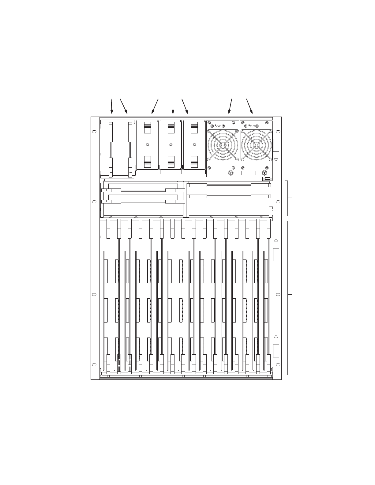
Planning Guide
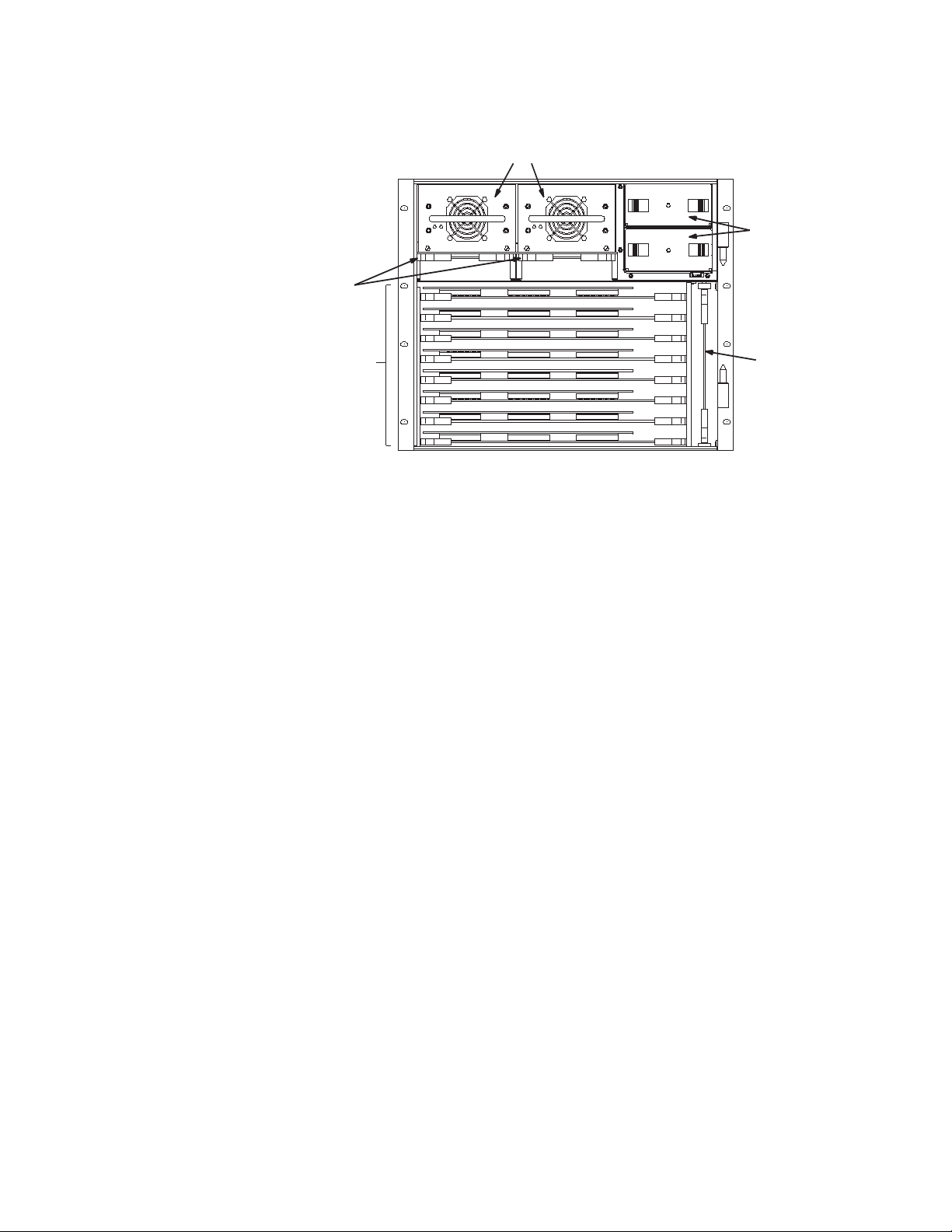
SR-33000 Sync
Reference / NR-33000
Broadlinx Board slots
Fan modules
FAN ALARM
FAN ALARM
Power supplies
Matrix board
Input/output boards
(configuration varies)
Figure 1. DV-33128 front view (door removed).
28 Planning and Installation Manual
Page 29
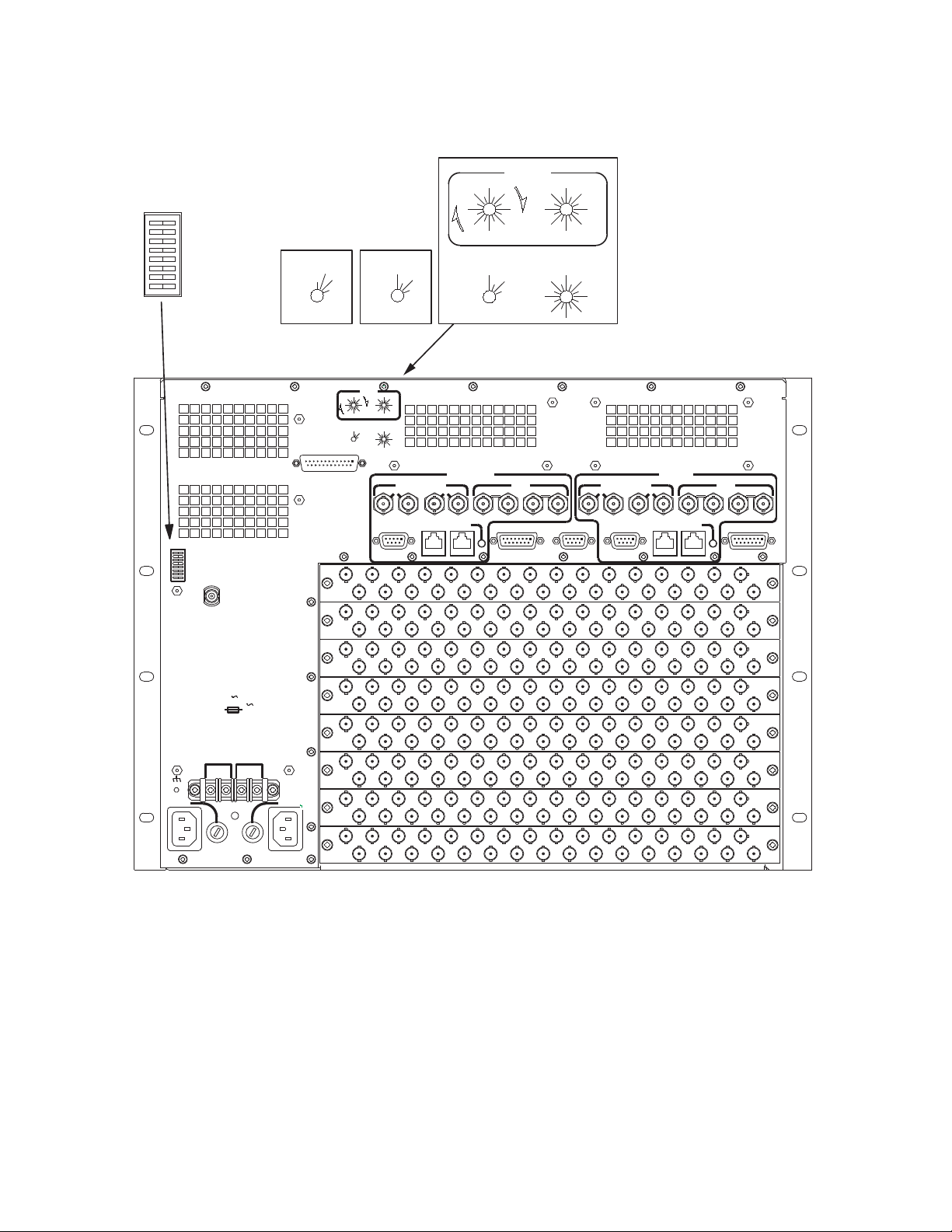
INPUT EXPAND
OUTPUT EXPAND
SYNC REDUNDANT
INT XPT CNTL
60Hz ENABLE
A
B
C
Figure 2. DV-33128 rear panel.
MONITOR
512
DV-33512 DV-33128
GPIO/TC
1024
1536
2048
96
80
64
48
32
MONITOR
112
16
128
0
16
48
80
112
0
256
MONITOR
DV-33256
128 x 256
8
LEVEL
SUPER
32
64
12
96
384
512
12
14
10
FRAME
14
10
0
15
1
13
11
79
8
0
15
1
13
11
9
7
8
256
768
512
1024
2
3
4
5
6
2
3
4
5
6
OUTPUT MONITOR
SECONDARY
96
80
64
48
32
ULTRA
MONITOR
Trinix Frame
LEVEL
SUPER
0
32
112
16
48
64
80
16
112
96
0
128
384
256
512
REF IN
434
12
FRAME
12
0
2
14
15
1
13
3
4
5
11
79
10
6
8
0
2
14
15
1
13
3
4
5
11
7
9
10
6
3
OUTPUT MONITOR
PRIMARY
12
REF IN
12
IP EXPAND
OP EXPAND
VIT REDUNDANT
INT XPT
60Hz ENABLE
A
B
C
ALARM
WARNING: FOR CONTINUED PROTECTION
AGAINST RISK OF FIRE, REPLACE ONLY
WITH SAME TYPE AND RATING OF FUSE
115: 6.0A 250V SLOW BLOW
230: T2.5A 240V
AUTO SELECT
100-130V/200-240V
6.0A/2.5A
47-63HZ
DC IN + DC IN -
PS B PS A
L
E
N
N
E
L
97-128
OUTPUTS
65-9633-64
OUTPUTS
1-32
OUTPUTS OUTPUTS
97-128
INPUTS
65-96
INPUTS
33-64
INPUTS
1-32
INPUTS
LAN BCOM BUS
CONSOLE B
17
17
17
17
17
17
17
17
19
18
1
2
19
18
1
2
19
18
1
2
19
18
1
2
19
18
1
2
19
18
1
2
19
18
1
2
19
18
1
2
21
20
3
4
21
20
3
4
21
20
3
4
21
20
3
4
21
20
3
4
21
20
3
4
21
20
3
4
21
20
3
4
CROSSPOINT BUS CONTROL
23
22
6
5
23
22
6
5
23
22
6
5
23
22
6
5
23
22
6
5
23
22
6
5
23
22
6
5
23
22
6
5
CONSOLE A
28
27
26
25
24
7
8
9
10
26
25
24
7
8
9
10
26
25
24
7
8
9
10
26
25
24
7
8
9
10
26
25
24
7
8
9
10
26
25
24
7
8
9
10
26
25
24
7
8
9
10
26
25
24
7
8
9
10
12
11
28
27
12
11
28
27
12
11
28
27
12
11
28
27
12
11
28
27
12
11
28
27
12
11
28
27
12
11
COM BUS
29
13
29
13
29
13
29
13
29
13
29
13
29
13
29
13
LAN A
CROSSPOINT BUS
31
30
30
30
30
30
30
30
30
32
14
15
16
31
32
14
15
16
31
32
14
15
16
31
32
14
15
16
31
32
14
15
16
31
32
14
15
16
31
32
14
15
16
31
32
14
15
16
Planning and Installation Manual 29
Page 30
Planning Guide
OK
DC
VADJ
OK
AC DCOKAC
OK
VADJ
FAN ALARM
FAN ALARM
FAN ALARM
SR-33000 Sync Reference /
NR-33000 Broadlinx Board
slots
Fan modules Power supplies
Matrix boards
Input/output
boards
(configuration
varies)
Figure 3. DV-33256 front view (door removed).
30 Planning and Installation Manual
Page 31

Figure 4. DV-33256 rear panel
See page 29 for detail
Trinix Frame
SECONDARY
NIC B
31
OP
MON
42
COM BUS
PRIMARY
NIC A
OP
MON
COM BUS
PS B
PS B
L
E
N
INPUTS INPUTS
17
1
1
18
2
2
19
3
3
20
4
4
21
5
5
22
6
6
23
7
7
24
8
8
25
9
9
26
10
10
27
11
11
28
12
12
29
13
13
30
14
14
31
15
15
32
16
16
DC INPUT
42 - 54 VDC
30-24 AMPS
INPUTS
33-641-32
17
18
19
20
21
22
23
24
25
26
27
28
29
30
31
32
PS A
IN EXPAND
OP EXPAND
VIT REDUNDANT
INT XPT CNTL
60Hz ENABLE
A
B
C
96
80
64
48
32
ULTRA
MONITOR
3
CONSOLE
REF
IN
4
LEVEL
0
SUPER
0
14
2
32
15
112
16
1
13
48
3
12
64
4
11
5
80
79
112
16
6
10
96
8
0
FRAME
128
0
14
384
2
256
15
1
13
512
3
12
4
5
11
79
6
10
8
CONTROL
GPIO/TC
B
1
CONSOLE
REF
IN
2
CROSSPOINT BUS
A
DC IN -DC IN +
WARNING: FOR CONTINUED PROTECTION
PS A
N
E
L
INPUTSINPUTS
17
1
2
3
4
5
6
7
8
9
10
11
12
13
14
15
16
17
1
18
18
2
19
19
3
20
20
4
21
21
5
22
22
6
23
23
7
24
24
8
25
25
9
26
26
10
27
27
11
28
28
12
29
29
13
30
30
14
31
31
15
32
32
16
AGAINST RISK OF FIRE, REPLACE ONLY
WITH SAME TYPE AND RATING OF FUSE
115: 12.5A 250V SLOW BLOW
230: T6.3A 240V
AUTO SELECT
100-130V/200-240V
10.0A/5.0A
47-63HZ
OUTPUTS OUTPUTS
OUTPUTS
17
1
2
3
4
5
6
7
8
9
10
11
12
13
14
15
16
17
1
18
18
2
19
19
3
20
20
4
21
21
5
22
22
6
23
23
7
24
24
8
25
25
9
26
26
10
27
27
11
28
28
12
29
29
13
30
30
14
31
31
15
32
32
16
OUTPUTS
OUTPUTS
1
2
3
4
5
6
7
8
9
10
11
12
13
14
15
16
OUTPUTS OUTPUTSOUTPUTS
17
1
18
2
19
3
20
4
21
5
22
6
23
7
24
8
25
9
26
10
27
11
28
12
29
13
30
14
31
15
32
16
17
17
1
18
18
2
19
19
3
20
20
4
21
21
5
22
22
6
23
23
7
24
24
8
25
25
9
26
26
10
27
27
11
28
28
12
29
29
13
30
30
14
31
31
15
32
32
16
OUTPUTS
17
1
2
3
4
5
6
7
8
9
10
11
12
13
14
15
16
17
1
18
18
2
19
19
3
20
20
4
21
21
5
22
22
6
23
23
7
24
24
8
25
25
9
26
26
10
27
27
11
28
28
12
29
29
13
30
30
14
31
31
15
32
32
16
INPUTS
129-160
225-256193-224129-160 161-19265-9633-64 97-1281-3297-12865-96
17
1
1
18
2
2
19
3
3
20
4
4
21
5
5
22
6
6
23
7
7
24
8
8
25
9
9
26
10
10
27
11
11
28
12
12
29
13
13
30
14
14
31
15
15
32
16
16
INPUTS INPUTS
17
1
18
2
19
3
20
4
21
5
22
6
23
7
24
8
25
9
26
10
27
11
28
12
29
13
30
14
31
15
32
16
INPUTS
17
18
19
20
21
22
23
24
25
26
27
28
29
30
31
32
ALARM
INPUTS
193-224161-192 225-256
17
1
1
18
2
2
19
3
3
20
4
4
21
5
5
22
6
6
23
7
7
24
8
8
25
9
9
26
10
10
27
11
11
28
12
12
29
13
13
30
14
14
31
15
15
32
16
16
17
18
19
20
21
22
23
24
25
26
27
28
29
30
31
32
Planning and Installation Manual 31
Page 32

Planning Guide
Rear view. See page 29
and page 33 for detail
Figure 5. DV-33512 main chassis and associated power supply unit.
SR-33000 Sync
Reference /
NR-33000
Broadlinx Board
slots
Fan modules
Input/output
boards
(configuration
varies)
INPUTS
481 - 512
PRIMARY
SECONDARY
FAN ALARM
FAN A
INPUTS
449 - 480
INPUTS
FAN ALARM
FAN B
417 - 448
385 - 416 225 - 256 193 - 224 161 - 192
VADJ
OK
OK
65 - 96 33 - 6497 - 128
INPUTS
DCAC
Power supply unit may be
VADJ
OK
AC
OK
DC
FAN ALARM
FAN F
POWER ALARM IFC
INPUTSINPUTSINPUTS
1 - 32
mounted above or below
main chassis
A
1
B
A
2
B
OP
MON
A
3
B
A
4
B
1
2
REF
IN
3
4
ACDC
OKOK
VADJ
PS CPS A
DCAC
OKOK
VADJ
PS DPS B
FAN ALARM
FAN ALARM
FAN C
OUTPUTS
OUTPUTSOUTPUTSINPUTSINPUTS
OUTPUTSOUTPUTS
97 - 128
129 - 160
OUTPUTS
INPUTS 257 - 512 / OUTPUTS 1 - 256
OUTPUTS
65 - 96
OUTPUTS
33 - 64
OUTPUTS
FAN ALARM
FAN EFAN D
INPUTS
1 - 32
Matrix boards
Input/output
boards
(configuration
varies)
INPUTS
353 - 384
INPUTS
INPUTS 1 - 256 / OUTPUTS 1 - 256
INPUTS 257 - 512 / OUTPUTS 257 - 512
INPUTS 1 - 256 / OUTPUTS 257 - 512
OUTPUTSINPUTS
INPUTSINPUTS
257 - 288289 - 320321 - 352
353 - 384
321 - 352
289 - 320
OUTPUTS
257 - 288
OUTPUTS
481 -512
OUTPUTS OUTPUTS
417 - 448449 - 480
OUTPUTS
OUTPUTS
OUTPUTS
OUTPUTS
385 - 416
INPUTS
INPUTSINPUTS
INPUTS
INPUTS
129 - 160
161 - 192
193 - 224225 - 256
32 Planning and Installation Manual
Page 33

Figure 6. DV-33512 main chassis and power supply chassis.
RP-33500
board. See
page 29 for
detail
Trinix Frame
DC INPUT 2 NOT FUSED
42 - 54 VDC
30 - 24 AMPS
DC IN +
DC IN -
DC INPUT 1 NOT FUSED
42 - 54 VDC
30 - 24 AMPS
DC IN + DC IN -
A
B
A
B
OP
MON
A
B
A
B
REF
IN
1
2
3
4
1
2
3
4
ULTRA
MONITOR
XPT BUS
LEVEL
SUPER
0
32
96
112
16
80
48
64
64
80
48
112
16
96
32
0
FRAME
1024
512
1536
2048
PS IFC FAN IFC
COM BUSCOM BUS
0
14
15
1
13
3
12
5
11
79
8
0
14
15
1
13
3
12
5
11
9
7
10
ALARM
2
4
610
2
4
6
8
INPUT EXPAND
OUTPUT EXPAND
SYNC REDUNDANT
INT XPT CNTL
60Hz ENABLE
A
B
C
INPUTS
129 - 160
AC INPUT: 100-240 V ~, 10.0-5.0A, 50-60Hz
100-120V: 12.5A, 250V, SLO BLO
200-240V: T6.3A, 250V
PS D
L
E
N
161 - 192
DC OUTPUT 2
42 - 54 VDC
30 - 24 AMPS
DC INPUT 2
42 - 54 VDC
30 - 24 AMPS
193 - 224
DC OUT -DC OUT +
DC IN -DC IN +
PS C PS A
N
L
INPUTS
INPUTS
INPUTS
OUTPUTS
225 - 256
385 - 416
E
WARNING: FOR CONTINUED PROTECTION
AGAINST RISK OF FIRE, REPLACE ONLY
WITH SAME TYPE AND RATING OF FUSE
OUTPUTS
417 - 448
OUTPUTSINPUTS
OUTPUTS
OUTPUTS
449 - 480
AC INPUT: 100-240 V ~, 10.0-5.0A, 50-60Hz
PS B
E
OUTPUTS
481 - 512
257 - 288
DC OUTPUT 1
42 - 54 VDC
30 - 24 AMPS
DC OUT + DC OUT -
DC INPUT 1
42 - 54 VDC
30 - 24 AMPS
100-120V: 12.5A, 250V, SLO BLO
200-240V: T6.3A, 250V
L
N
INPUTS
OUTPUTS
289 - 320
OUTPUTS
321 - 352
OUTPUTS
353 - 384
INPUTS
257 - 288
INPUTS
289 - 320
INPUTS
321- 352
INPUTS
353 - 384
PRIMARY
REF IN
1
COM BUS
NIC A
2
CONSOLE A
SECONDARY
REF IN
3
GPIO/TC
COM BUS
XPT BUS
NIC B
FRAME IFC
4
DC IN -DC IN +
CONSOLE B
CONTROL
N
E
L
Planning and Installation Manual 33
Page 34

Planning Guide
Figure 7. Signal flow and power supply system for DV-33512 router.
Powered by
PS C and PS D
Inputs
385-512
Powered by
PS A and PS B
Outputs
129-256
1-128
Outputs
1-128
Inputs
Input/Output
boards
DM-33501/2
Matrix boards
Input/Output
Inputs
257-384
Outputs
257-384
Outputs
385-512
Inputs
129-256
boards
Primary Supplies
PS A
PS B
PS C
PS D
34 Planning and Installation Manual
Page 35

Power Supplies
Two power supply types are used in the Trinix routing family, one type
for the 128 chassis and another for the 256 and 512 chassis. Both types,
which share the same feature set, are OEM products. The power supplies differ primarily in power delivered, size, and weight.
The 128 and 256 chassis are designed for two power supplies. The
optional (and recommended) second supply provides redundancy and
increased reliability due to “load sharing” - both supplies work less,
creating less strain and decreasing the likelihood of failure of either
unit.
In AC power applications, the 512 chassis is equipped with two power
supplies mounted in a separate chassis. For redundancy, space is provided for two additional supplies (recommended). The 512 power
supply chassis may be mounted above or below the main chassis,
depending on video cable routing requirements (or weight distribution
requirements).
All power supplies are front loading and hot swappable and each has
its own fan for cooling. Automatic line sensing technology is used to
adapt the supply to all major power standards throughout the world.
The back panel of the chassis provides a separate AC connector for each
supply and a third connection for a 48 VDC input.
Trinix Frame
The power supplies each deliver 48 volts to all components and the
individual components convert down the voltages for their particular
need.
For additional redundancy, it is possible to operate the router with a
combination of internal power supplies and a external DC power
source.
Planning and Installation Manual 35
Page 36

Planning Guide
Right side Rear Left side
IN
IN
IN
OUT OUT
Cooling System
The Trinix uses fan modules (FM-33000) for cooling the main chamber of
the chassis. A fan module consists of two blower-type fans that are
housed in a mechanical assembly. The 128 x 128 chassis uses two modules, the 256 x 256 chassis uses three, and the 512 uses six. The fan
modules are front-loading and hot-swappable.
Airflow openings for the 128 chassis are shown in Figure 8. Air is taken
in from the sides of the chassis (primarily the left side), where the air is
drawn across the I/O cards, past the matrix card, and up to the top rear
of the chassis where it is expelled. A small amount of air is drawn from
the right side of the chassis as well to help cool the matrix board.
Figure 8. Airflow openings for DV-33128 chassis.
36 Planning and Installation Manual
Page 37

Trinix Frame
Right side
Rear
Left side
IN
IN
IN
OUT
ININ
IN
Right side Rear Left side
OUT
IN
IN
IN IN
IN IN
IN
IN
OUT
Airflow openings for the 256 and 512 chassis are shown in Figure 9 and
Figure 10. Air is taken in from the bottom of the chassis (cut-outs are
located on the very bottom of the sides), and from the central area of the
left and right sides. This air is then drawn up through all of the I/O
cards as well as the matrix boards to the top rear of the chassis and
expelled out the back.
Figure 9. Airflow openings for DV-33256 chassis.
Figure 10. Airflow openings for DV-33512 power supply and main chassis.
Planning and Installation Manual 37
Page 38

Planning Guide
Using a central set of fan modules to cool the main chamber eliminates
the possibility of cooling loss in one area due to failure of a single fan.
If a fan does fail, the system will continue to operate, providing a safe
interval during which the failed fan can be replaced and the system
returned to normal redundant operation.
Sync Reference Options
For synchronous vertical interval switching the same sync reference
signal must be sent to the control system (e.g., Jupiter CM-4000) and to
the Trinix. (The Trinix will operate without a sync connection but
switching will be non-synchronous.) Each sync input uses looping 75
ohm BNC connectors.
The sync signal can be NTSC or PAL black burst, or tri-level (HD) sync,
and up to four sync signals can be mixed within the same chassis on an
output-board basis. For example, NTSC sync could be used for one set
of 32 outputs and HD sync for another set of 32 outputs.
In DV-33128 and DV-33256 units, one or two independent sync signals
can be connected to a NR-33000 Broadlinx board and either of these can
then be selected for use on each output board. Adding a second Broadlinx board provides a total of four independent sync sources.
In DV-33512 units, which are normally supplied with an SR-33500
Sync/OPM board, up to four independent sync sources can be connected and any of the four can be selected for each output board. If
desired, an NR-33000 board can be installed in the associated power
supply chassis to provide Broadlinx capability. It is also possible to
divide the sync sources between the SR-33500 and the Broadlinx board
but the maximum number of sync sources is always four.
Sync Redundant mode
For all systems, two Broadlinx boards can be operated in Sync Redundant mode where the sync signal(s) are looped through each board; if
the primary Broadlinx board fails the system will switch automatically
to the secondary board. However, for redundant operation the number
of sync signals is limited to two.
For sync reference details, see page 107.
Output Monitoring
With the DV-33128 and DV-33256 chassis, two pairs of output monitor
ports are provided by the NR-33000 board (one side of each pair is
inverted). Two additional dual ports are optionally available when a
second NR-33000 is added; this would provide a total of four monitor
ports.
38 Planning and Installation Manual
Page 39

With the DV-33512 chassis, the SR-33500 Sync/OPM board provides
32 Output
Card
Matrix Card
(128 x 128)
32 Output
Card
32 Output
Card
32 Output
Card
32 Input
Card
32 Input
Card
32 Input
Card
32 Input
Card
four monitoring ports.
For configurations that require multiple chassis, the monitor signals are
brought through a PE-33016 Port Expander used as a combiner (see
page 59).
Signal Flow
Trinix is a “three-board” routing system, where the input board, output
board, and matrix board are the basic modules.
Shown below is the signal flow through a 128 x 128 routing system.
Inputs are received and outputs are delivered to the rear of the chassis
directly with a connection to the rear panels (no cabling).
Figure 11. Input and output routing through matrix board for 128 x 128 switcher.
Trinix Frame
For a description of the various input, output, and matrix cards available for Trinix, see page 83.
Planning and Installation Manual 39
Page 40

Planning Guide
• Save/recall settings
• Mono mode
•Setup on/off
•Chroma kill
•Comb/trap filter
•AGC on/off
• Manual gain control
• ACC on/off
•Manual chroma
control
• Blank video (per
VBI line)
• Add setup (per VBI
line)
• Reserve VBI line for
data
• Horizontal timing
• Detail enhancement
• Display channel
status
• Insert Error Detection and Handling
(EDH) data
• Contrast / Y gain
• Saturation /
chroma gain
• Brightness / Y
offset
•Hue / chroma
phase
• Notch decode on/
off (VBI)
• Chroma kill (VBI)
Analog Processing Control
The VI-33100 “universal” input module accepts analog as well as
digital signals. Adjustments for analog signals include the following:.
For more information about the VI-33100 module, please refer to
Section 6-Analog Input Processing.
Pre-wiring
All Trinix switchers are pre-wired to the size of the chassis. That is, a
128-chassis is essentially pre-wired to 128 x 128 with all rear panels and
BNCs in place. The 256-chassis is pre-wired to 256 x 256. By convention,
switcher sizes are shown as:
M x N (P x Q)
This indicates that the functional router size is M x N and is pre-wired
to (P x Q). For Trinix pre-wiring is only possible in multiples of 128 x
128, as that is the smallest chassis size increment.
Connector Numbering
Late-model Trinix routers have video input/output connectors that
begin with “1” instead of “0.” An adhesive overlay set, which indicates
connector groups using a 0-based numbering scheme (e.g., “Inputs 031,” “Inputs 32-63,” etc.) is provided for customers who are using a 0based control system such as Jupiter.
40 Planning and Installation Manual
Page 41

Alarm System
There are two Trinix alarm classes: primary and secondary. A secondary alarm is asserted when a single fan has failed or when the secondary NR/SR Broadlinx board has taken control of the system. All
other alarms (multiple fan failure, power supply failure, etc.) are considered primary alarms.
All major components include a local alarm LED. NR/SR-33000 boards
have separate LEDs for primary and secondary alarms.
The master alarm indicator is a tri-color LED on the front panel
(“Power/Alarm”) where green indicates normal operation, red indicates a primary alarm, and amber indicates a secondary alarm.
The rear panel “Alarm” BNC can be configured to report primary
alarms only or both primary and secondary alarms. The factory default
configuration is to report both. (DV-33128 and DV-33256 configuration
is via a jumper on the NR/SR-33000 board, as shown on page 119 and
page 120. DV-33512 configuration is via a jumper on the RP-33500 512
x 512 Rear Panel board as shown on page 122.)
Trinix Frame
Electrically, the Alarm BNC operates according to SMPTE standard
269M-1999. When an alarm is asserted, the circuit associated with the
Alarm connector will present a low impedance to an external current
source circuit provided by the customer. See Figure 12.
Planning and Installation Manual 41
Page 42

Planning Guide
EXTERNAL CIRCUIT
(EXAMPLE)
NOT TO EXCEED
24 VDC @ 20 mA
REAR PANEL BNC
Figure 12. Rear panel master alarm circuit (left) and example of customer-supplied indicator
circuit (right)
.
All of the alarm and status information is also gathered by the Broadlinx technology to make it available to the user via web pages. For more
information, see page 22.
42 Planning and Installation Manual
Page 43

Duplication and Expansion
Trinix routers are designed to duplicate/expand inputs and outputs
using passive splitter/combiner expansion panels.
Note For Jupiter-controlled (0-based) systems, the input/output numbers in
Note Frame numbers are determined by the input/output blocks served by the
Note Unused connectors should be terminated for optimum performance.
Output Duplication - Dual
The PE-33016 Port Expander is a passive, transformer-based module
that can be used to provide two copies of the same signal. Functionality
is bi-directional and depends on connections only; no configuration is
needed. Figure 13 and Figure 14 show a splitting application. Note that
the unused connectors should be terminated for optimum performance.
Duplication and Expansion
the following discussion should be decreased by one (1). For example,
block 1-256 should be understood as block 0-255, etc.
particular frame. E.g., for a DV-33256 router, inputs 1-256 and outputs
1-256 must be connected to frame zero. For more information about
frame numbering, see page 146.
Figure 13.
1 - 256
Frame 0
Trinix
256 x 256
1 - 256
16
PE 33016
used as
splitters
1 - 256
Dual outputs
Planning and Installation Manual 43
Page 44

Planning Guide
1B
1A
1B
1A
Exterior sideInterior side
(Terminated)
Figure 14. PE-33016 used to provide 16 dual outputs.
In the splitting application, the PE-33016 Port Expander can be used to
provide dual outputs in groups of 16 outputs. All outputs are noninverting. For example, a 256 x 256 router could be arranged as follows:
256 inputs x 240 single outputs and 16 dual outputs - uses 1 PE-33016
or
256 inputs x 224 single outputs and 32 dual outputs - uses 2 PE-33016s
or
256 inputs x 208 single outputs and 48 dual outputs - uses 3 PE-33016s...
etc.
Figure 15 shows a router with 240 single outputs and 16 dual outputs.
44 Planning and Installation Manual
Page 45

Figure 15.
Duplication and Expansion
1 - 16
Frame 0
1 - 256
Trinix
256 x 256
1
PE 33016
used as
splitter
1 - 16
Dual outputs
17 - 256
Single outputs
In this application, 16 of the PE-33016 rear BNCs can be used for inputs
(outputs from the router) and all 32 of the front BNCs can be used for
1
outputs.
Up to 16 PE-33016 modules can be mounted in the MK-33000 Mounting
Kit, which is eight rack units high and approximately four inches deep.
Figure 16 shows a 128 input router with a single PE-33016 mounted in
an MK-33000; this provides 112 single outputs and 16 dual outputs.
Figure 17 shows a 256 input router with 256 dual outputs; this arrange-
ment requires 16 PE-33016 Port Expanders.
1.
All unused connectors must be terminated. 16 terminators are supplied with each PE-33016. See page 87.
Planning and Installation Manual 45
Page 46

Planning Guide
Dual outputs
123 16
1A
These 16
cables connect
to rear of PE
1B
2A
2B
3A
3B
16A
16B
Terminate
Unused BNCs
PE-33016-1
Exterior
390-1796-00
PE-33016-1
Interior
390-1797-00
Figure 16. Use of single PE-33016 to provide dual outputs for 16 switcher outputs
46 Planning and Installation Manual
Page 47

Duplication and Expansion
A
B
C
16 PE-30016 Expander
Modules in MK-33000
Mounting Kit
EXTERIOR
INTERIOR
3.25 in.
(82 mm)
Figure 17. PE-33016 Port Expanders used to provide 256 dual outputs for 256 input switcher.
Planning and Installation Manual 47
Page 48

Planning Guide
Output Duplication - Quad
The PE-33008 Port Expander can be used to provide quad outputs in
groups of 16 outputs. All outputs are non-inverting. A 128 x 128
switcher could be arranged as follows:
128 inputs x 112 single outputs and 16 quad outputs - uses 2 PE-33008s
or
128 inputs x 96 single outputs and 32 quad outputs - uses 4 PE-33008s
or
128 inputs x 80 single outputs and 48 dual outputs - uses 6 PE-33008s... etc.
In this application, the eight PE-33008 rear BNCs are used for inputs
(outputs from the router) and all 32 of the front BNCs are used for out-
1
Up to 16 PE-33008 modules can be mounted in an MK-33000
puts.
Mounting Kit, which is 8 RU high and approximately 4 inches (100 mm)
deep.
1.
All unused connectors must be terminated with 75 ohm terminators; for PE-33008 applications terminators must be sup-
plied by end-user.
48 Planning and Installation Manual
Page 49

Figure 18. Use of 2
PE 33008s to provide
quad outputs for 16
switcher outputs
3A
3B
3C
3D
Quad outputs
2A
2B
2C
2D
Duplication and Expansion
Figure 18 shows a 128 input router with two PE-33008s mounted in an
MK-33000; this provides 112 single outputs and 16 quad outputs. A 256
input router with 128 single outputs and 128 quad outputs would
appear similar to the system shown in Figure 17; this arrangement
requires 16 PE-33008 Port Expanders.
Connections
to 2nd
PE-33008
are similar
123 8
1A
1B
1C
1D
These cables
connect to
rear of PE
8A
8B
8C
8D
Terminate
Unused BNCs
Terminate
Unused BNCs
PE-33008-1
Exterior
390-1795-00
PE-33008-1
Interior
390-1794-00
Planning and Installation Manual 49
Page 50

Planning Guide
1A
1B
Exterior sideInterior side
1A
1B
Expanded Systems
The PE-33016 and PE-33008 Port Expanders can be used to “combine”
outputs for an input expansion application. In Figure 19 and Figure 20,
a PE-33016 is downstream of the router. The router will present only
one of the two possible signals to each combiner, which will produce
two copies of that signal. Note that any unused connectors should be
terminated for optimum performance. The port expanders are
mounted in an MK-33000 Mounting Kit as described previously
(page 46).
Figure 19. PE-33016 used as a combiner. Only one of the input signals will be present at a time,
and this signal is duplicated.
Expanded configurations include:
1024 inputs x 512 dual outputs 1024 inputs x 1024 dual outputs
512 inputs x 1024 outputs 2048 inputs x 2048 outputs
1024 inputs x 1024 outputs
Some of these configurations are shown on the following pages. Notice
that the same port expander type is used for both downstream combining (for input expansion) and upstream splitting (for output expansion). All outputs are non-inverting.
50 Planning and Installation Manual
Page 51

Figure 20. Examples of input and output expansion.
1 - 512
Inputs expanded
to 1024
513 - 1024
Frame 0
Trinix
512 x 512
Frame 1
Trinix
512 x 512
1 - 512
32
PE 33016
used as
combiners
512 - 1024
1 - 512
Inputs expanded
to 1024 (restricted)
1 - 512
Dual outputs
Frame 0
Trinix
512 x 512
Duplication and Expansion
1 - 16
17 - 512
32
PE 33016
used as
combiners
17 - 512
Dual outputs
1 - 512
32
PE 33016
used as
splitters
1 - 512
1 - 512
Frame 0
Trinix
512 x 512
Frame 2
Trinix
512 x 512
1 - 512
Outputs
expanded
to 1024
513 - 1024
17 - 512
513 - 1024
32
PE 33016
used as
splitters
Frame 1
Trinix
512 x 512
1 - 16
1 - 512
17 - 512
17 - 512
Frame 0
1 - 512
Trinix
512 x 512
Outputs
expanded
to 1024
(restricted)
Frame 2
513 - 1024
Trinix
512 x 512
The term “restricted” refers to a wiring scheme where some signal
paths are not available. For example, the second system shown in
Figure 20 will not allow outputs 1-16 to receive inputs 513-1024.
Planning and Installation Manual 51
Page 52

Planning Guide
1 - 512 Dual outputs
Figure 21. 1024 x 1024 system.
1 - 512
32
PE-33016
used as
splitters
1 - 512
Frame 0
Trinix
512 x 512
Frame 2
Trinix
512 x 512
1 - 512
513 - 1024
32
PE-33016
used as
combiners
1 - 512
Inputs and outputs
expanded to 1024
513 - 1024
32
PE-33016
used as
splitters
513 - 1024
513 - 1024
Frame 1
Trinix
512 x 512
Frame 3
Trinix
512 x 512
1 - 512
513 - 1024
32
PE-33016
used as
combiners
513 - 1024
Dual outputs
52 Planning and Installation Manual
Page 53

Figure 22. 1024 x 2048 system.
Frame 0
Duplication and Expansion
Inputs
1 - 512
64
PE-33008
used as
1 x 4
splitters
Inputs expanded to 1024
1 - 512
1 - 512
1 - 512
1 - 512
Trinix
512 x 512
Frame 2
Trinix
512 x 512
Frame 8
Trinix
512 x 512
Frame 10
Trinix
512 x 512
Frame 1
32
1 - 512
PE-33016
used as
Dual outputs
combiners
Outputs expanded to 2048
32
513 - 1024
PE-33016
used as
Dual outputs
combiners
Inputs
513 - 1024
64
PE-33008
used as
1 x 4
splitters
513 - 1024
513 - 1024
513 - 1024
513 - 1024
Trinix
512 x 512
Frame 3
Trinix
512 x 512
Frame 9
Trinix
512 x 512
Frame 11
Trinix
512 x 512
32
PE-33016
used as
combiners
32
PE-33016
used as
combiners
1025 - 1536
Dual outputs
1537 - 2048
Dual outputs
Planning and Installation Manual 53
Page 54

Planning Guide
Inputs
1 - 512
Inputs expanded to 2048
Inputs
513 - 1024
Figure 23. 2048 x 1024 system.
1 - 512
32
PE-33016
used as
splitters
1 - 512
513 - 1024
32
PE-33016
used as
splitters
513 - 1024
Frame 0
Trinix
512 x 512
Frame 2
Trinix
512 x 512
Frame 1
Trinix
512 x 512
Frame 3
Outputs expanded to 1024
64
PE-33008
1 - 512
used as
Dual outputs
4 x 1
combiners
Inputs
1025 - 1536
Inputs
1537 - 2048
32
PE-33016
used as
splitters
32
PE-33016
used as
splitters
1025 - 1536
1025 - 1536
1537 - 2048
1537 - 2048
Trinix
512 x 512
Frame 4
Trinix
512 x 512
Frame 6
Trinix
512 x 512
Frame 5
Trinix
512 x 512
Frame 7
64
PE-33008
used as
4 x 1
combiners
513 - 1024
Dual outputs
Trinix
512 x 512
54 Planning and Installation Manual
Page 55

Figure 24. 2048 x 2048 system.
Duplication and Expansion
Inputs and outputs expanded to 2048
Inputs
513 - 1024
Inputs
1 - 512
PE-33008
used as
splitters
1 x 4
64
PE-33008
used as
1 x 4
splitters
513 - 1024
513 - 1024
64
513 - 1024
513 - 1024
Frame 1
Trinix
512 x 512
Frame 3
Trinix
512 x 512
Frame 9
Trinix
512 x 512
Frame 11
Trinix
512 x 512
1 - 512
1 - 512
1 - 512
1 - 512
1025 - 1536
Frame 0
Trinix
512 x 512
Frame 2
Trinix
512 x 512
Frame 8
Trinix
512 x 512
Frame 10
Trinix
512 x 512
Frame 4
Trinix
512 x 512
64
PE-33008
used as
4 x 1
combiners
64
PE-33008
used as
4 x 1
combiners
1 - 512
Dual outputs
513 - 1024
Dual outputs
Inputs
1025 - 1536
Inputs
1537 - 2048
64
PE-33008
used as
1 x 4
splitters
PE-33008
used as
1 x 4
splitters
1025 - 1536
1025 - 1536
1537 - 2048
1537 - 2048
64
1537 - 2048
1537 - 2048
Frame 5
Trinix
512 x 512
Frame 7
Trinix
512 x 512
Frame 13
Trinix
512 x 512
Frame 15
Trinix
512 x 512
1025 - 1536
Frame 6
Trinix
512 x 512
Frame 12
Trinix
512 x 512
Frame 14
Trinix
512 x 512
64
PE-33008
used as
4 x 1
combiners
64
PE-33008
1025 - 1536
used as
Dual outputs
4 x 1
combiners
1537 - 2048
Dual outputs
Planning and Installation Manual 55
Page 56

Planning Guide
Termination for Pre-wired Expansion Frames
Figure 25. LD-33100 Loader board
As described above, unused BNC connectors on port expanders should
be terminated for best performance. However, it may be desirable to
install an empty or partially stuffed frame and associated cabling to
simplify future expansion, and when such cabling connects to a port
expander that is carrying active signals, special termination hardware
is required. Since the presence of pre-wired cabling will not permit
standard BNC terminators to be installed on the expander, an LD-33100
Loader board is installed in the associated frame in place of an input or
output board to provide correct termination.
Input Expansion
For example, Figure 26 shows a 512 x 512 system expandable to 1024 x
512:
Figure 26.
Frame 0
1 - 512
1 - 512
32
PE 33016
used as
combiners
Installed pre-wiring
Output slots should be terminated
using LD-33100 Loader boards
outputs
1 - 512
Future input
wiring
Trinix
512 x 512
Frame 1
(unused)
Trinix
512 x 512
Frame 1 contains no input or output boards, but wiring has already
been installed between Frame 1 and the PE-331016 Port Expanders.
56 Planning and Installation Manual
Page 57

Duplication and Expansion
Input 1B - from Frame 1 Output 1.
Input 1A - from Frame 0 Output 1
Output 1A - to downstream equipment
Output 1B - not used. Termination provided by
Termination provided by LD-33000
75 ohm BNC terminator
in upstream Trinix frame.
Now consider Output 1 of Frame 0. This sign al is conn ected to Input 1A
of the first PE-33016 Port Expander. See Figure 27.
Figure 27. Detail of one PE-33016 shown in Figure 26.
In this example:
• Only Input 1A and Output 1A are presently functional.
• Following the rule that unused connectors should be terminated,
Output 1B is fitted with a 75 ohm BNC terminator.
• Input 1B is pre-wired to Frame 1, so there is no place for a terminator. In this case, termination will be provided by an LD-33100
Loader board installed in output board slot “1-32” of Frame 0. Furthermore, in this example all 16 output slots of Frame 0 should have
an LD-33000 installed.
• When the system is upgraded to 1024 x 512, the LD-33000 boards
will be removed and replaced by output boards. Cabling to the port
expanders is already in place.
The concepts in this example apply equally to systems with PE-33008
Port Expanders. For example, they would apply to a 1024 x 1024 system
that is pre-wired for expansion to 2048 x 1024 (similar to the system
shown on page 54, where LD-33100 Loader boards would be installed
in place of output boards in Frames 4 through 7).
Planning and Installation Manual 57
Page 58

Planning Guide
Input 1A - from upstream equipment
Output 1A - to Frame 0 Input 1
Input 1B - not used. Termination
provided by 75 ohm BNC terminator
Output 1B - to Frame 1 Input 1.
Termination provided by LD-33100
in Frame 1.
Output Expansion
Similarly, LD-33100 Loader boards may also be used for outputexpandable systems. For example, Figure 28 shows a 512 x 512 system
expandable to 512 x 1024:
Figure 28.
Frame 0
1 - 512
Future output
wiring
1 - 512
32
PE 33016
used as
splitters
Installed pre-wiring
Input slots should be terminated
using LD-33100 Loader boards
1 - 512
Trinix
512 x 512
Frame 1
(unused)
Trinix
512 x 512
Again, considering one signal path (Figure 29), pre-wired cable connections do not allow for installation of individual terminators. Instead,
LD-33100 Loader boards are installed in the unused frame, but in this
case they are installed in the input slots.
Figure 29. Detail of one PE-33016 shown in Figure 28.
Input and Output Expansion
The rules just described for use of LD-33100 Loader boards will also
apply to systems designed for expansion of both inputs and outputs.
An example would be a 512 x 512 pre-wired for expansion to 1024 x
1024 (similar to the system shown on page 52). Only chassis 0 would be
active in the 512 x 512 router, so only the port expanders connected to
Frame 0 would be in use. Frame 1’s inputs are connected to the top left
PE; while Frame 2’s outputs are connected to the top right PE. Therefore
Frame 1’s input slots would require LD-33100s and Frame 2’s output
slots would require LD-33100s. No LDs would be needed for Frame 3.
58 Planning and Installation Manual
Page 59

Monitoring with Expanded Systems
In expanded systems, output monitor signals must be brought through
a combiner. An example of an output-expanded system in shown in
Figure 30; an input-expanded system is shown in Figure 31.
Note Output monitoring is not available for input-expanded systems con-
trolled by an SR-33000 Sync/OPM board.
Figure 30. Monitoring with output-expanded system.
1 - 256
Duplication and Expansion
Frame 0
1 - 256
Trinix
256 x 256
1 - 256
1 - 256
Frame 0
Trinix
256 x 256
PE-33016s
used as
splitters
1 - 256
1 - 256
PE-33016s
combiners
32
used as
Frame 2
Trinix
256 x 256
Output monitor video
Dual outputs
Output monitor video
257 - 512
PE-33016
used as
combiner
1 - 256
QC station
Frame 1
257-512
Trinix
256 x 256
257 - 512
Output monitor video
PE-33016
used as
combiner
QC station
Figure 31. Monitoring with input-expanded system.
Planning and Installation Manual 59
Page 60

Planning Guide
Protected Paths
Overview
The protected path function is designed to monitor router outputs that
are feeding critical downstream equipment and, in the event of signal
loss, automatically select the output that i s carrying the same signal and
trigger the system alarm.
This function assumes the following:
• HO-33120 HD/SD Output Board(s) are providing the output
signal(s) to be monitored. These boards allow individual outputs to
be enabled or disabled using software controls.
• Protection is provided for paths, i.e., input/output pairs. The
installer must identify critical outputs and an associated critical
input for each. For redundancy, two paths must be defined: a “primary” path and a failover “secondary” path.
• Protected pairs should be hard wired to back-panel connectors that
will provide the most independent possible paths through the
router. For example, the two paths should use different input
boards and different output boards. Depending on router size, the
two paths may also be able to use different matrix boards and different power sources.
• For full redundancy, two copies of each protected input must be
wired to the router. For example, the master control switcher output
could be sent through a passive splitter upstream of the router. One
copy is used for the primary path, and the other for the secondary
path. If an upstream splitter is used, steps must be taken to boost the
gain for the appropriate block of inputs (as described in the Trinix
manual).
• The primary output and the secondary output must be wired to a
passive combiner, the output of which is connected to the downstream equipment. The protected path software will automatically
boost individual outputs as needed for proper gain level through
the splitter. Outputs not configured for protected path operation
should be set for gain levels as described in the manual. (The protected path software will override the manual settings as needed.)
• The control system (e.g. Encore or Jupiter) must be operated so that
the secondary path is always ready to provide a copy of the protected signal. For example, the operator would switch the Master
Control output to the transmitter on the primary path; the control
system would then switch the secondary path automatically. For
more information, see Encore Configuration on page 184 or Jupiter
Configuration on page 189.
60 Planning and Installation Manual
Page 61

Splitter
Combiner
Primary path
Output Status
Signal OK, driver ON
Output assigned to
protected path, driver OFF
Protected Paths
Figure 32 shows an example of a DV-33512 router with a pair of pro-
tected paths.(Depending on system requirements, the upstream splitter
may or may not be needed.) The signal detector monitors the primary
path and if necessary will disable the primary path output driver and
enable the secondary path output driver. Notice that the two paths use
independent sets of hardware.
Figure 32. Example of protected paths for DV-33512 router
Output Status
Signal OK, driver ON
Output assigned to
protected path, driver OFF
Splitter
Powered by
PS C and PS D
Inputs
Inputs
385-512
257-384
Powered by
PS A and PS B
Outputs
129-256
Outputs
257-384
1-128
Outputs
Outputs
385-512
Input 1Output 1
1-128
Inputs
Inputs
129-256
Input/Output
boards
DM-33501/2
Matrix boards
Input/Output
boards
Combiner
Output 257Input 257
Secondary path
The following discussion describes the protected path planning process.
Planning and Installation Manual 61
Page 62

Planning Guide
Planning
Note The following discussion is based on a “1-based” numbering scheme. If
you are using a “zero-based” numbering system, subtract “1” from all
instances of input/output numbers.
DV-33512
The recommended protected path ranges for DV-33512 routers are as
follows:
Ta b l e 2.
Primary path Secondary path
Output Input Output Input
1-128 1-128 257-384 257-384
For example, to protect an output in the range 1-128, choose a corresponding input in the range 1-128; this will be the primary path. For the
secondary (failover) path, choose an output in the range 257-384 and a
corresponding input in the range 257-384.
Alternatively, the high-range of connectors can be used for the primary
path and the low range for the secondary path, as shown in Tab le 3 :
Ta b l e 3.
Primary path Secondary path
Output Input Output Input
257-384 257-384 1-128 1-128
Using either of these schemes will provide the most independent possible paths through a DV-33512, i.e., the primary path will use one set
of input, matrix, and output boards connected to one power source
while the secondary path will use a different set of boards connected to
a different power source.
Note that for a DV-33512 router the maximum number of protected
paths is 256.
62 Planning and Installation Manual
Page 63

Protected Paths
A more detailed example is shown in Tab le 4 . This table shows a
sequential wiring scheme for a system yet to be installed or a system
where cables will be re-arranged in a symmetrical pattern in order to
simplify protected path configuration.
Table 4. DV-33512 protected paths (example of sequential numbering)
Primary path Secondary path
Out In Out In
Name No. Name No. Name No. Name No.
AirPP 1 MCPP 1 AirSP 257 MCSP 257
Sat1PP 2 StuAPP 2 Sat1SP 258 StuASP 258
Sat2PP 3 StuBPP 3 Sat2SP 259 StuBSP 259
.. ..
.. ..
.. ..
NetPP 256 MainPP 256 NetSP 512 MainSP 512
The numbers shown here correspond to the connector numbers used
during router configuration (but not, in most cases, to the actual silk
screen number on the rear panel itself since the silk screen numbers
only run from “1” to “32.”)
In Jupiter-controlled systems, the “Name” in these tables corresponds
to the “logical input/output name” and the entries in the number
column correspond to the “physical” input/output number.
The next example applies to existing systems where re-arrangement of
cables in a sequential pattern is not practical or desirable:
Table 5. DV-33512 protected paths (example of non-sequential numbering)
Primary path Secondary path
Out In Out In
Name No. Name No. Name No. Name No.
AirPP 21 MCPP 12 AirSP 390 MCSP 265
Sat1PP 253 StuAPP 254 Sat1SP 413 StuASP 348
Sat2PP 109 StuBPP 98 Sat2SP 289 StuBSP 409
.. ..
.. ..
.. ..
NetPP 4 MainPP 256 NetSP 440 MainSP 454
Notice that in all cases the primary path I/O numbers are always in the
1-256 range while the secondary path I/O numbers are always in the
257-512 range.
Planning and Installation Manual 63
Page 64

Planning Guide
DV-33256
Recommended protected path ranges for DV-33256 routers are as follows:
Ta b l e 6.
Primary path Secondary path
Out In Out In
1-128 1-128 129-256 129-256
For example, to protect an output in the range 1-128, choose a corresponding input in the range 1-128; this will be the primary path. For the
secondary (failover) path, choose an output in the range 129-256 and a
corresponding input in the range 129-256.
This will provide the most independent possible paths through a DV33256, i.e., the primary path will use one set of input, matrix, and
output boards while the secondary path will use a different set of
boards.
CAUTION With a DV-33256, it isn’t possible to arrange completely independent
paths, i.e., paths that use different power supplies. Protected path configuration for DV-33256 routers provides redundancy for matrix boards
and input and output boards only.
Note that for a DV-33256 router the maximum number of protected
paths is 128.
A more detailed example is shown in Tab le 7 . This table shows a
sequential wiring scheme for a system yet to be installed or a system
where cables will be re-arranged in a symmetrical pattern in order to
simplify protected path operation.
Table 7. DV-33256 protected paths (example of sequential numbering)
Primary path Secondary path
Out In Out In
Name No. Name No. Name No. Name No.
AirPP 1 MCPP 1 AirSP 129 MCSP 129
Sat1PP 2 StuAPP 2 Sat1SP 130 StuASP 130
Sat2PP 3 StuBPP 3 Sat2SP 131 StuBSP 131
.. ..
.. ..
.. ..
NetPP 128 MainPP 128 NetSP 256 MainSP 256
64 Planning and Installation Manual
Page 65

Protected Paths
Splitter
Combiner
Output Status
Signal OK, driver ON
Output assigned to
protected path, driver OFF
The numbers shown here correspond to the connector numbers used
during router configuration (but not, in most cases, to the actual silk
screen number on the rear panel itself since the silk screen numbers
only run from “1” to “32.”)
In Jupiter-controlled systems, the “Name” corresponds to the “logical
input/output name” and the number corresponds to the “physical”
input/output number.
Figure 33. Example of protected paths for DV-33256 router
DM-33100
Matrix boards
Primary path
Splitter
Secondary path
Inputs
129-256
1-128
Outputs
129-256
Output 128Input 128
Outputs
1-128
Inputs
Input 1Output 1
Input/Output
boards
Output Status
Signal OK, driver ON
Output assigned to
protected path, driver OFF
Combiner
Planning and Installation Manual 65
Page 66

Planning Guide
The next example applies to existing systems where re-arrangement of
cables in a sequential pattern is not practical or desirable:
Table 8. DV-33256 protected paths (example of non-sequential numbering)
Primary path Secondary path
Out In Out In
Name No. Name No. Name No. Name No.
AirPP 21 MCPP 12 AirSP 190 MCSP 165
Sat1PP 53 StuAPP 54 Sat1SP 133 StuASP 248
Sat2PP 109 StuBPP 98 Sat2SP 189 StuBSP 129
.. ..
.. ..
.. ..
NetPP 4 MainPP 56 NetSP 144 MainSP 145
Notice that in all cases the primary path I/O numbers are always in the
1-128 range while the secondary path I/O numbers are always in the
129-256 range.
66 Planning and Installation Manual
Page 67

Protected Paths
DV-33128
Recommended protected path ranges for DV-33128 routers are as follows:
Ta b l e 9.
Primary path Secondary path
Out In Out In
1-32 1-32 33-128 33-128
33-64 33-64
65-96 65-96
97-128 97-128 1-96 1-96
1-32,
65-128
1-64,
97-128
For example, to protect an output in the range 1-32, choose a corresponding input in the range 1-32; this will be the primary path. For the
secondary (failover) path, choose an output in the range 33-128 and a
corresponding input in the range 33-128.
1-32,
65-128
1-64,
97-128
This will provide the most independent possible paths through a DV33128, i.e., the primary path will use one pair of input and output
boards while the secondary path will use a different pair of boards.
CAUTION With a DV-33128, it isn’t possible to arrange completely independent
paths, i.e., paths that use different matrix boards and power supplies.
Protected path configuration for DV-33128 routers provides redundancy
for input and output boards only.
Note that for a DV-33128 router the maximum number of protected
paths is 64.
A more detailed example is shown in Tab le 1 0. This table shows a
sequential wiring scheme for a system yet to be installed or a system
where cables will be re-arranged in a symmetrical pattern in order to
simplify protected path operation.
Table 10. DV-33128 protected paths (example of sequential numbering)
Primary path Secondary path
Out In Out In
Name No. Name No. Name No. Name No.
AirPP 1 MCPP 1 AirSP 33 MCSP 33
Sat1PP 2 StuAPP 2 Sat1SP 34 StuASP 34
Sat2PP 3 StuBPP 3 Sat2SP 35 StuBSP 35
.. ..
.. ..
.. ..
NetPP 64 MainPP 64 NetSP 128 MainSP 128
Planning and Installation Manual 67
Page 68

Planning Guide
The numbers shown here correspond to the connector numbers used
during router configuration (but not, in most cases, to the actual silk
screen number on the rear panel itself since the silk screen numbers
only run from “1” to “32.”)
In Jupiter-controlled systems, the “Name” corresponds to the “logical
input/output name” and the number corresponds to the “physical”
input/output number.
The next example applies to existing systems where re-arrangement of
cables in a sequential pattern is not practical or desirable:
Table 11. DV-33128 protected paths (example of non-sequential numbering)
Primary path Secondary path
Out In Out In
Name No. Name No. Name No. Name No.
AirPP 21 MCPP 12 AirSP 33 MCSP 33
Sat1PP 53 StuAPP 54 Sat1SP 1 StuASP 1
Sat2PP 109 StuBPP 95 Sat2SP 96 StuBSP 64
Notice that I/O numbers conform to the ranges shown in Tab le 9.
68 Planning and Installation Manual
Page 69

Worksheet for Protected Path Implementation
Based on the preceding examples, specific primary and secondary
paths should be identified and noted. The following worksheet is provided for this purpose.
Table 12. Protected paths worksheet
Primary path Secondary path
Output Input Output Input
Name No. Name No. Name No. Name No.
Protected Paths
Planning and Installation Manual 69
Page 70

Planning Guide
Control Systems
Jupiter Facility Control System
The Jupiter control system can be used to operate the Trinix router
using a VM-3000 or CM-4000 System Controller (Figure 34). The VM/
CM can receive switching commands from a variety of serial sources,
including Jupiter control panels or an automation computer.
Figure 34. Control connections to Jupiter Facility Control System (example).
Trinix routing
switcher(s)
10Base2
LAN
VM-3000
System
Controller
T
T
10/100BaseT
LAN
Media
converter
or hub
Ungrounded
=
T
50-ohm terminator
Jupiter file
server
Crosspoint bus
Crosspoint bus
terminator
MPK bus
T
Jupiter control panels
In this application, the Trinix is operated in the “external crossspoint
bus control” mode, during which the Broadlinx board releases control
of the crosspoint bus. Switch commands arriving at the crosspoint bus
connector on the rear of the chassis will be executed.
70 Planning and Installation Manual
Page 71

Control Systems
CC-2010 Matrix (Crosspoint Bus) Cable
Connection from a Jupiter VM-3000 or CM-4000 System Controller is
via a crosspoint bus cable, which can be supplied in 3, 10, 25, or 50 foot
lengths. The crosspoint bus connector is looped out in order to connect
the bus to the next item under crosspoint control.
Depending on the size of the switcher this bus may require intermediate buffering through a CB-3000 Control Buffer. A CB 3000 is required
in the following cases:
DV-33128 - eight or more chassis
DV-33256 - four or more chassis
DV-33512 - two or more chassis
The CB-3000 is described in detail in the Jupiter Installation and Operating manual.
In Trinix applications, the crosspoint bus must be terminated at the
point farthest from the control processor using a Crosspoint Bus Terminator, part number 01-053050-001.
The CC-2010 is a 10-conductor (plus ground) cable. Ready-made cables,
with installed 15-pin D male connectors, are available from Grass
Valley; see page 88.
All rear-panel crosspoint bus connectors are 15-pin D, female.
For those who wish to prepare their own cables, pin-outs are shown on
page 150. The cable itself should be Belden 9505 or equivalent. User-
supplied matrix cables for VDE installations require a ferrite core over
each end of the cable, adjacent to the connector. Details concerning
ferrite cores are given on page 150.
Jupiter Control System Installation
Refer to the Jupiter VM-3000 System Controller Installation and Operation Manual, part no. 071 8305 xx or the Jupiter CM-4000 System Controller Installation and Operation Manual, part no. 071 8261 xx for
control system installation details.
Planning and Installation Manual 71
Page 72

Planning Guide
SMS 7000 / Encore Control
These control systems use an Ethernet connection to the Broadlinx
application, which runs on the NR-33000 Sync/NIC/OPM board.
The system is operated in the “internal crosspoint bus control” mode,
during which the Broadlinx board sends commands to the crosspoint
bus.
LAN components are described below.
Refer to the SMS 7000 or Encore documentation for control system
planning information.
72 Planning and Installation Manual
Page 73

LAN and Com Bus Connections
The LAN (NIC) connections use a standard 10/100BaseT twisted pair
cable with RJ-45 connectors (Cat 5E Enhanced is recommended).
Shielded cable is also recommended, maximum length 60 meters.
Maximum length for unshielded cable is 100 meters.
LAN Monitoring Only (Jupiter Control)
In this arrangement the router is under Jupiter control and the only
purpose of the connection is LAN monitoring using Broadlinx web
pages or SNMP. See Figure 35.
Figure 35. LAN connections for LAN monitoring only (Jupiter Control)
LAN and Com Bus Connections
1
NIC B
connector
Trinix
Ethernet switch
Monitoring PC
NIC A
connector
If you plan on using a secondary Broadlinx board another Ethernet
cable must be connected from the “NIC B” jack to the network
switch.
If the Trinix LAN is connected to the Internet the connection should
be made through a firewall.
1.
Compliance with EEC, EMC, EN series, UL- 1950, and CSA C22.2 No. 950-M89 standards requires use of a shielded cable.
Planning and Installation Manual 73
Page 74

Planning Guide
SMS Control
In this arrangement the router is under SMS control via a LAN connection. The PC is used to configure the SMS and is also available for
Broadlinx or SNMP monitoring. See Figure 36.
Figure 36. SMS connections to Trinix.
NIC B
connector
Trinix
Ethernet switch
7000 SMS
MCPU frame
Ethernet
connector
PC
NIC A
connector
If you plan on using a secondary NR-33000 board another Ethernet
cable must be connected from the “NIC B” jack to the network
switch.
If the Trinix LAN is connected to the Internet the connection should
be made through a firewall.
74 Planning and Installation Manual
Page 75

LAN and Com Bus Connections
Encore Control
In this arrangement the router is under Encore control via a LAN connection. The PC is used to configure the Encore and is also available for
Broadlinx or SNMP monitoring. Figure 37 shows the recommended
connections when the system is equipped with redundant NR-33000
boards and redundant Encore controllers.
Figure 37. Encore connections to Trinix
PC
Ethernet switch
Ethernet switch
Primary Encore controller
NIC A
connector
EN1
EN2
Trinix
Encore control panels
EN1
Secondary Encore controller
EN2
NIC B
connector
Ethernet switch
Planning and Installation Manual 75
Page 76

Planning Guide
Com Bus
Trinix frame
with NR-33000
Sync/NIC/
OPM board
(Broadlinx
board)
In multi-frame systems, a “Com Bus” is used to loop through each
frame, up to a maximum of four. The Com Bus is intended to provide
switcher monitoring of multiple frames using Broadlinx web pages or
SNMP. The Com Bus uses a 10/100BaseT (Cat 5 twisted pair) cable with
RJ-45 connectors. Shielded cable is recommended, maximum length 60
1
meters.
Figure 38.
Maximum length for unshielded cable is 100 meters.
Trinix frames
with SR-33000
Sync/OPM
or SR-33500
Sync/OPM
boards
Com Bus cable
(see discussion
for specifications)
In DV-33512 systems, if the power supply chassis is equipped with an
NR-33000 Broadlinx board, a Cat 5 twisted pair cable must be installed
between the power supply chassis Com Bus connector associated with
the NR board and one of the main chassis Com Bus connectors.
If there are additional DV-33512 main frames in the system, and they do
not have Broadlinx boards, then the Com Bus should be daisy-chained
to those frames also.
For an illustration, see page 102.
1.
Compliance with EEC, EMC, EN series, UL- 1950, and CSA C22.2 No. 950-M89 standards requires use of a shielded cable.
76 Planning and Installation Manual
Page 77

System Monitoring Applications
For a detailed description of Broadlinx web page monitoring using
Internet Explorer, see Broadlinx / Internet Explorer Monitoring on
page 166.
For a brief description of system monitoring using SNMP/NetCentral,
see SNMP/NetCentral Monitoring on page 23.
System Monitoring Applications
Planning and Installation Manual 77
Page 78

Planning Guide
Specifications
Electrical
Connectors: 75 ohm BNC
Input cards: 32 inputs each.
Output cards: 32 outputs each.
Matrix cards: DM-33100: 128 inputs x 128 outputs.
Level: 800 mV p-p (+/-10%) 75 ohm terminating
Return loss: HD: >/=15 dB from 5 MHz to 1.5 GHz
General
DM-33512: 256 inputs x 256 outputs.
For additional information about the various input, output,
and matrix cards available for Trinix, see page 83.
Video Inputs
SD: >/=15 dB from 5 MHz to 540 MHz
Sync Inputs
Level: Nominal 1 Vp-p (+/-6 dB) video or black burst.
Tri-level sync also accepted
Video standard: NTSC/PAL/HDTV, auto-detected
Return loss: >/=40 dB from 100 kHz to 20 MHz
>/=30 dB from 20 MHz to 30 MHz
Video Outputs
Level: 800 mV p-p +/-10% 75 ohm
Return loss: >/=15 dB from 5 MHz to 1.5 GHz (except Monitor outputs)
Performance Characteristics
Maximum data rate: 1.5 Gbps
Minimum data rate: 3.072 Mbps
Signal standards: SMPTE 292M-1998,
fall times correspond to SMPTE 292M)
Equalization: SI-33110 Input Card (SD): automatic up to 300 meters of
Belden 1694A, 250 meters of Belden 8281 or equivalent coax
cable for SD equalizer at 270 Mbps. Reducing to 150 meters
at 540 Mbps.
1
SMPTE 259M-19971 (Output rise and
1.
See Glossary
78 Planning and Installation Manual
Page 79

HI-33110 Input Card (SD/HD): automatic up to 100 meters
of Belden 1694A or equivalent coax cable.
VI-33100 Input Card (SD/HD): For digital SD operation,
automatic up to 300 meters of Belden 1694A or equivalent
coax cable. For HD operation, automatic up to 100 meters
of Belden 1694A or equivalent coax cable.
HI-33200 Input Card (SD/HD): For SD operation, automatic up to 300 meters of Belden 1694A or equivalent coax
cable. For HD operation, automatic up to 100 meters of
Belden 1694A or equivalent coax cable.
Data reclocking: Switch selectable on an output-by-output basis.
The HO-33110 Output Board provides individual selection
of reclocking for 1.485 Gbps or non-reclocking for all data
rates.
The HO-33120 Output Board provides individual selection
of reclocking On or Off for the supported data rates. The
data rate for reclocking is automatically selected by the circuitry on the board for 1.485 Gbps, 540 Mbps, 360 Mbps,
270 Mbps, 177 Mbps, and 143 Mbps. Other data rates will
not be reclocked.
The SO-33110 Output Board is non-reclocking.
Specifications
Output jitter: </= 0.2 unit interval
AC Power Input
Mains connection: IEC Connector, separate mains input for each power sup-
ply module
Voltage range: 100-240 VAC 50-60 Hz, universal, auto-ranging (fuses must
be selected and installed as appropriate for mains voltage)
Operating current 128 x 128 frame: approx. 5.36 A @ 100 VAC, approx. 2.23 A
@ 240 VAC.
256 x 256 frame: approx. 9.36 A @ 100 VAC, approx. 3.90 A
@ 240 VAC
512 x 512 frame: approx. 19.08 A @ 100 VAC; approx. 7.63 A
@ 240 VAC
Inrush current 128 x 128 frame: 49.05 A
256 x 256 frame: 55.0 A
512 x 512 frame: 45 A
Hold-up time: Minimum 20 msec at full load
Conducted emissions: per FCC Class B, EN55022 Class B
Power Supply DC Output
Voltage: +48 (+/-0.5) VDC
Current: 128 x 128 frame: 12.5 A/supply (full redundancy).
Planning and Installation Manual 79
Page 80

Planning Guide
256 x 256 frame: 26 A/supply (full redundancy).
512 x 512 frame: approx. 26 A/supply (full redundancy).
Current sharing: Yes, maximum 20% differential unbalance
Ripple/noise: <200 mVp-p
DC Power Input
Input voltage range 42-54 VDC
Operating current 128 x 128 frame: approx. 9.5 A @ 48 VDC.
256 x 256 frame: approx. 16 A @ 48 VDC.
512 x 512 frame: approx. 34 A @ 48 VDC.
Inrush current 128 x 128 frame: 15 A.
256 x 256 frame: 21 A.
512 x 512 frame: approx. 25 A.
Alarm
The relay connector is a BNC type and meets SMPTE 269M-1999 (see Glossary).
Environmental
0 to +35 degrees C (+32 to +95 F)
Physical
14 inches (8 RU) high x 19 in. wide x 17.50 in. deep (356 x 483 x 445 mm)
26.25 inches (15 RU) high x 19 in. wide x 17.5 in. deep (667 x 483 x 445 mm)
Main chassis: 49 inches (28 RU) high x 19 in. wide x 17.5 in. deep (1245 x 483 x 445
mm)Power supply chassis: 7 inches (4 RU) high x 19 in. wide x 21 in. deep (178 x
483 x 533 mm)
14 inches (8 RU) high x 19 in. wide x approximately 4 in. deep (356 x 483 x 100
mm)
128 x 128 frame
256 x 256 frame
512 x 512 frame
MK-33000 Mounting Kit (for port expansion)
80 Planning and Installation Manual
Page 81

Configuration
Quick Look
Building block size: 32 Inputs or 32 Outputs
Options: SD or HD rate I/O modules
Standards supported: SMPTE 259M-1997, SMPTE 292M-1998
Standard connectors: 75-Ohm BNC
Output monitor: Yes, 2 standard
Sync reference input:Yes, 2. Granularity: per 32 outputs
Control options: Jupiter, SMS 7000, Encore
Configuration
Dual outputs, quad outputs
Additional monitor outputs (2)
Redundant sync inputs (2)
Redundant monitor/status/control
Redundant power supplies
Chassis, Board, Weight and Power Summary for Select Matrix Sizes
Ta b l e 13 .
Matrix Size
# of Chassis 1111111 1
# Input Boards 1234567 8
# Output Boards 1234567 8
# of Matrix Boards 1111444 4
Weight in pounds
(kilograms)
Power Consumption* (W) ~350 ~400 ~440 ~480 ~850 ~900 ~950 ~1000
32
x
32
75
(34)
*Approximate
64
x
64
128 Chassis 256 Chassis
81
(37)
96
x
96
88
(40)
128
x
128
94
(43)
160
x
160
163
(74)
192
x
192
169
(77)
224
x
224
176
(80)
256
x
256
182
(83)
Planning and Installation Manual 81
Page 82

Planning Guide
Ta b l e 14 .
Matrix Size
# of Chassis 1 1 1 1 2 2
# Input Boards 8 8 16 16 32 32
# Output Boards 8 16 8 16 24 32
# of Matrix Boards 1 2 2 4 6 8
Weight* in pounds
(kilograms)
# of RUs 32 32 32 32 64 64
Power Consumption* (W) ~1000 ~1400 ~1600 ~2000 ~3500 ~4000
Ta b l e 15 .
Matrix Size
768
x
512
256
x
256
~300
(~140)
768
x
768
256
x
512
~350
(~160)
1024
x
512
512
x
256
512 Chassis
~350
(~160)
1024
x
1024
512
x
512
~400
(~180)
512
768
~750
(~340)
x
512
x
1024
~800
(~360)
2048
x
2048
512 Chassis
# of Chassis 2 4 2 4 16
# Input Boards 24 48 32 64 256
# Output Boards 32 48 32 64 256
# of Matrix Boards 6 9 8 16 64
Weight* in pounds
(kilograms)
# of RUs 64 192 64 192 512
Power Consumption* (W) ~4000 ~6000 ~4000 ~8000 ~32000
~750
(~340)
~1400
(~640)
~800
(~360)
~1600
(~730)
~6400
(~2900)
*Approximate
82 Planning and Installation Manual
Page 83

Ordering Information
Trinix routing systems are ordered as a base frame; a set of input,
output, and matrix boards; and options.
Frames
TRX-DV-33128
128 x 277P MAESTRO.xls128 Frame with 1 PS, 1 Broadlinx, 2 Fan Modules. 8 RU
TRX-DV-33256
256 x 256 Frame with 1 PS, 1 Broadlinx, 3 Fan Modules. 15 RU
TRX-DV-33512
512 x 512 Frame with 2 PS, 1 Broadlinx, 6 Fan Modules. 32 RU
Ordering Information
Input, Output, and Matrix Boards
Input and output boards each have 32 inputs or outputs and can be
grouped into SD and HD blocks within a frame. The matrix board is
available in two sizes.
TRX-SI-33110
SD Input Module - consists of a 16-input base board (SI-33110) and a 16input mezzanine board (SI-33011), providing 32 inputs. Supports data
rates of 3 to 540 Mbps. A “gain cell” is included on this board to be used
in conjunction with the port expanders in order to create multi-chassis
routers.
TRX-HI-33200
SD/HD Input Module - consists of a 16-input base board (HI-33200)
and a 16-input mezzanine board (HI-33201), providing 32 inputs. The
module supports data rates of 3 Mbps to 1.485 Gbps. A “gain cell” is
included on this board to be used in conjunction with the port
expanders in order to create multi-chassis routers.
TRX-VI-33100
Video Input Module - consists of a 16-input “universal” base board (VI-
33100) and a 16-input digital-only mezzanine board (HI-33201), pro-
viding 32 inputs.
• The VI-33100 Universal base board auto-senses and accepts 16 composite analog SD, digital SD, or digital HD signals in any combination and passes them in digital SD or digital HD form (as
appropriate) to the Trinix matrix board. When analog signals are
Planning and Installation Manual 83
Page 84

Planning Guide
received, an extensive set of gain, phase, filtering, and other adjustments are available for each signal. For a list of these adjustments,
see page 40.
• The HI-33201 SD/HD Digital Input mezzanine board auto-senses
and accepts a second set of 16 digital SD or digital HD signals in any
combination and passes them in digital SD or digital HD form (as
appropriate) to the Trinix matrix board.
TRX-HI-33200
SD/HD Digital Input Module - consists of a 16 input base board (HI-
33200) and a 16 input mezzanine board (HI-33201), providing a total of
32 inputs. Each board auto-senses and accepts 16 digital SD or digital
HD signals in any combination and passes them in digital SD or digital
HD form (as appropriate) to the Trinix matrix board. The TRX-HI-33200
is similar to the TRX-VI-33100 but is not fully stuffed.
TRX-SO-33110
SD Output Module, non-reclocked - consists of a 16 output base board
(SO-33110) and a 16 output mezzanine board (SO-33011), providing a
total of 32 outputs.
A “gain cell” is included on this board to be used in conjunction with
the port expanders in order to create multi-chassis routers as well as
dual or quad outputs. A switch is included to select one of four synchronizing inputs.
TRX-HO-33110
HD Output Board, 1.5 G reclocked - consists of a 16 output base board
(HO-33110) and a 16 output mezzanine board (HO-33011), providing a
total of 32 outputs.
Each output can be set for Auto Detect “ON” or “OFF.” When Auto
Detect is ON the signal will be checked to see if it is a valid HD signal
running at 1.485 Gbps; if so, the signal will be reclocked; if not, it will
be bypassed. When Auto Detect is OFF the output signal is never
reclocked. A “gain cell” is included on this board to be used in conjunction with the port expanders in order to create multi-chassis routers as
well as dual or quad outputs. A switch is included to select one of four
synchronizing inputs.
TRX-HO-33120
Universal Output Module, multi-rate reclocker - consists of a 16-output
base board (HO-33120) and a 16-output mezzanine board (HO-33121).
Each output can be set for Auto Detect “ON” or “OFF.” When Auto
Detect is ON the signal will be checked to see if it is a valid HD or SD
signal running at a supported data rate; if so, the signal will be
reclocked; if not, it will be bypassed. When Auto Detect is OFF the
output signal is never reclocked. A “gain cell” is included on this board
to be used in conjunction with the port expanders in order to create
84 Planning and Installation Manual
Page 85

Ordering Information
multi-chassis routers as well as dual or quad outputs. A switch is
included to select one of four synchronizing inputs. A list of data rates
supported by the HO-33120 Output Board is shown on page 79.
Protected path operation requires HO-33120 Output Modules in the
paths to be protected.
TRX-DM-33100
Digital Matrix Board - 128 x 128 for use with 128 and 256 frame
Contains 32 instantiations of a 32 x 16 crosspoint IC. It handles both SD
and HD data rates and is used in both the 128 and 256 chassis. It has a
memory refresh circuit which is used to keep the configuration of the
crosspoints in the event of some power interruption to the controlling
element. One card is needed for all configurations in the 128 chassis and
1, 2, or 4 are needed for the 256 chassis depending on the needed matrix
size.
TRX-DM-33512
Digital Matrix Board - 256 x 256 for use with 512 frame
This module consists of two circuit boards interconnected, each with a
256 x 128 matrix function. The matrix board uses redundant power-conditioning circuitry and 144 x 144 crosspoint ICs (used as 128 x 128) each
with its own control circuit. A 512-chassis, fully stuffed to 512 x 512
inputs and outputs, requires four of these modules.
Options
Additional video signal cards
Additional input, output, and matrix cards can be selected for spares or
an additional level of signal routing.
Power Supplies and Fans
A redundant power supply and spare can be added if desired.
TRX-PS-33100
Power Supply - 128 frame
TRX-PS-33200
Power Supply - 256 and 512 frame
TRX-FM-33000
Fan Module
Planning and Installation Manual 85
Page 86

Planning Guide
NIC/Sync/OPM Boards
TRX-BL-33000
Broadlinx board- consists of one NR-33000 NIC/Sync/OPM board and
associated software; combines synchronization, network interface, and
output monitoring functions.
Requires TRX-CTRL-CPL for SMS 7000 / Encore control or TRX-CTRLXPT for Jupiter control.
Sync Functions: The BL-33000 includes two sync-reference inputs,
which can be NTSC, PAL or Tri-level inputs.
NIC Functions: The NIC (Network Interface Controller) functions
include the network connection as well as a computing element that is
the heart of the Broadlinx hardware. This controller communicates with
the internal micro-controllers within the Trinix chassis as well as with
the outside world via the network connection. The NIC is a 10/100
connection that will communicate via HTTP and (optionally) SNMP
protocols.
Output Monitor: The BL-33000 provides output monitoring for DV33128 and DV-33256 systems. Two output monitor ports are included,
each with an inverted and non-inverted output. (These output monitor
ports are not available when the NR-33000 is installed in a DV-33512
chassis. DV-33512 monitoring is provided by the SR-33500 board,
described below.)
1
Adding a second BL-33000 provides two extra sync inputs,
two extra
output monitor ports, and redundant Broadlinx functionality.
TRX-CTRL-CPL
Trinix Info Command: CPL Control
TRX-CTRL-XPT
Trinix Info Command: XPTControl
NR-33000
See BL-33000 Broadlinx option.
TRX-SR-33500
Sync Reference / Output Monitor (OPM) Board. This board is used in
DV-33512 units only.
Sync functions: The SR-33500 includes four looping sync-reference 75
ohm BNC inputs which can be NTSC, PAL or Tri-level inputs.
1.
Although a DV-33512 chassis may include SR-33000 and NR-33000 boards (each with two sync inputs), and an SR-33500
board (with four sync inputs), the maximum number of usable sync inputs for any Trinix chassis remains four.
86 Planning and Installation Manual
Page 87

Ordering Information
Output monitor: Four output monitor ports are included, each with an
inverted and non-inverted output.
Broadlinx capability can be added by installing an BL-33000 Broadlinx
option in the associated power supply chassis.
Port Expanders
As described above (page 43), these passive, bi-directional modules
provide dual and quad outputs as needed for signal duplication and
system expansion.
TRX-PE- 33016
The PE-33016 Port Expander has 32 connectors on one side and 32 on
the other. Sometimes referred to a “2 x 2 module,” the PE-33016 can be
used as a 2 to 1 combiner (with dual outputs) or a 1 to 2 splitter. One or
many of these can be installed as the need requires. Using this as a
splitter provides dual outputs (non-inverting) for 16 outputs at a time.
Installs in MK-33000 Mounting Kit. Since no application uses more than
48 connectors, each PE-33016 is supplied with 16 BNC 75 ohm terminators. Additional connectors, if needed, must be provided by the enduser.
TRX-PE-33008
The PE-33008 is a 4 x 1 expander module that has eight BNC connectors
on one side and 32 on the other. This unit can be used as a 4 to 1 combiner or a 1 to 4 splitter. One or many of these can be installed as the
need requires. Using this as an output splitter makes quad outputs for
eight outputs at a time. Installs in MK-3000 Mounting Kit. All unused
connectors must be terminated with 75 ohm BNC terminators (not supplied by Grass Valley).
1
TRX-MK-33000
The MK-33000 Mounting Kit, which accommodates up to 16 port
expander modules, is eight rack units high and approximately 4 inches
deep.
TRX-LD-33100
Loader module. These boards are available for use in systems that have
been pre-wired for later expansion. They provide correct termination
for installed but unused cables that connect to an “active” Port
Expander module. For more information, see page 56.
SNMP/NetCentral Software Options
Order one license key per frame being monitored via SNMP/NetCentral. Note: For an overview of NetCentral and associated applications,
see page 22.
Planning and Installation Manual 87
Page 88

Planning Guide
TRX-NETCEN-128
NetCentral SNMP Agent License Key for Trinix 128 x 128 frame
TRX-NETCEN-256
NetCentral SNMP Agent License Key for Trinix 256 x 256 frame
TRX-NETCEN-512
NetCentral SNMP Agent License Key for Trinix 512 x 512 frame
Miscellaneous
MNC-XPT-CBL-3
Crosspoint Bus Cable, 3 ft. (0.91 m)
MNC-XPT-CBL-10
Crosspoint Bus Cable, 10 ft. (3 m)
MNC-XPT-CBL-25
Crosspoint Bus Cable, 25 ft. (7.6 m)
MNC-XPT-CBL-50
Crosspoint Bus Cable, 50 ft. (15.2 m)
Crosspoint Bus Terminator
Included with all systems. Part number: 01-053050-001.
CB-3000B
Crosspoint Bus Buffer. Provides eight additional crosspoint bus outputs. 1 RU.
110/220 VAC.
• DV-33128 systems with eight or more chassis
• DV-33256 systems with four or more chassis
• DV-33512 systems with two or more chassis
MNC-CBLBNC-02
BNC to BNC Cable, 2 meters
TRX-HD128-KIT
Trinix 128HD Spares Kit. Includes 1 ea. BL-33000, DM-33100, FM-33000,
HI-33200, HO-33120, and PS-33100
TRX-HD256-KIT
A CB-3000 is required in the following cases:
Trinix 256HD Spares Kit. Includes 1 ea. BL-33000, DM-33100, FM-33000,
HI-33200, HO-33120, and PS-33200
88 Planning and Installation Manual
Page 89

Ordering Information
TRX-HD512-KIT
Trinix 512HD Spares Kit. Includes 1 ea. BL-33000, DM-33512, FM-33000,
HI-33200, HO-33120, and PS-33200
TRX-MAN
Trinix Planning and Installation Manual
Planning and Installation Manual 89
Page 90

Planning Guide
90 Planning and Installation Manual
Page 91

Installation
Summary of Installation Procedure
The following is a summary of the steps needed for installation of the
Trinix Routing Switcher System. Additional details may be found elsewhere in this manual as indicated.
1. Before unpacking the equipment, inspect the shipping carton for
evidence of freight damage. After unpacking carefully inspect all
equipment for freight damage.
If the contents have been damaged, notify the carrier and Grass
Valley (see page 4 for contact information). Retain all shipping
cartons and padding material for inspection by the carrier.
Section 3
Do not return damaged merchandise to Grass Valley until an appropriate claim has been filed with the carrier and a material return
authorization number has been received from Grass Valley.
2. If the switcher is received without a rack, it should be mounted in a
19-inch wide frame or other suitable enclosure that provides power
and cooling facilities for the equipment.
a. It may be necessary to install special rack spacers so that the
router's access door can be opened far enough to permit
removal of components on the right side of the chassis (such as
power supply modules). The spacers, which are available on
request, should only be installed when the rack's mounting
holes are recessed more than 0.6 inch (15.2 mm) from the front
surface of the rack. For more information, see page 96.
b. Some switchers are supplied with PE-33016 Port Expanders,
which depending on the configuration can be used to provide
dual outputs, quad outputs, input expansion, output
expansion, and multi-chassis output monitoring. For
illustrations of port expander applications, see page 43.
c. Power requirements are shown on page 79.
d. Environmental limits are shown on page 80.
Planning and Installation Manual 91
Page 92

Installation
3. Power supplies are factory-installed and auto-sensing. No field
adjustment should be necessary.
Power supplies for 512 x 512 (DV-33512) switchers are mounted in
a separate chassis and require cabling (supplied) from the “DC
Output” connector of the power supply chassis to the “DC Input”
connector of the switcher chassis. The 512 power supply chassis
may be mounted above or below the main chassis, depending on
video cable routing requirements (or weight distribution requirements).
For additional power supply information, see page 104.
4. For 512 x 512 (DV-33512) switchers:
CAUTION In order to avoid damaging the switcher, power must be Off before
installing the “IFC” cables as described in the following step.
a. Install the “IFC” cables (supplied) between (1) the power
supply chassis and main chassis, and (2) between the main
chassis center section and the fan module section.
For an illustration, see page 102.
5. If the system is supplied with PE-33016 Port Expanders, check the
input/output expansion DIP switches and jumpers for correct
position.
These switches and jumpers are normally set at the factory based on
the configuration shown in the sales order. For more information,
see page 124.
6. On High Definition switchers:
a. Signal reclocking mode can be set for each output on an output
board. The factory default setting is “Auto,” meaning that
properly-formed, standard data rate signals will be reclocked
but other signals will be bypassed (not reclocked). See page 134
for details.
SD switchers do not include reclocking.
7. Make sure all cards are all seated in their backplane sockets.
This should not normally be an issue since the boards are held in
place with locking extractors.
92 Planning and Installation Manual
Page 93

8. Connect the desired input and output video cables.
To permit proper vertical interval switching, the inputs must be
aligned within plus/minus 1/4 line with respect to the reference
signal.
The use of 75 ohm BNC connectors (rather than 50 ohm) is recommended for HDTV applications.
If the system includes port expanders, all unused BNC connectors
must be terminated with 75 ohm terminators.
On DV-33512 units, the output connectors are not arranged in a leftto-right sequence. The rear-panel labels are correct.
Note Labels for “0-based” numbering schemes are available. See page 40.
9. For “protected path” operation, the Broadlinx software can be
configured to monitor router outputs that are feeding critical
downstream equipment (such as a transmitter). If the “primary”
output signal is interrupted, the system will automatically select the
“secondary” output that is carrying the same signal and trigger a
system alarm. For wiring information, see page 60. For
configuration instructions, see Section 5-Protected Path Configuration.
10. If the router is equipped with VI-33100 “universal” input boards,
and analog signals are received, an extensive set of gain, phase,
filtering, and other adjustments are available for each signal. For
more information about the VI-33100 module, please refer to
Section 6-Analog Input Processing.
11. Connect the appropriate house reference signal(s).
Depending on the system, up to four independent sync references
can be used. For system diagrams, see page 107.
12. Re-configure the switch point if desired.
The switch point is factory-set to the recommended video line for
the standard that is detected. A V-phasing feature, available with
the NR-33000, SR-33000 with Rev B FPGA Software Update, and
SR-33500 allows the user to adjust the switch point from -1 line to
+2.5 lines if necessary. For more information, see page 117.
Note If you make adjustments on the SR-33500 as part of this step, you may
want to wait until all remaining steps in this list have been followed and
any additional adjustments made before reinstalling the board.
13. Select the desired sync line on each Output board.
This applies to systems with more that one sync reference. Each
output board provides a block of 32 outputs and by factory default
each block is assigned to sync line 1, which corresponds to the “Pri-
Planning and Installation Manual 93
Page 94

Installation
mary Ref IN 1” connector on the rear panel. If additional references
are used, DIP switches are set to assign each board to one of four
possible sync lines. See page 123.
14. If output monitoring is required, refer to the installation
instructions starting on page 137.
15. On multi-chassis systems, the Frame number switches should be
checked. See page 146.
16. Connect the switcher to the control system:
— For Jupiter control system connections and settings, see
page 148.
— For SMS 7000 or Encore control system connections and
settings, see page 153.
17. LAN and Com Bus connections and configuration of the Broadlinx
board (NR-33000 NIC/Sync/OPM board) are covered in the above
discussions about control systems.
The Broadlinx board is equipped with a plug-in, rechargeable
lithium-ion battery used to back up switcher status for Encore-controlled systems. The battery is rated for approximately 500 power
cycles. If there is a power failure, and the battery fails to provide
power, the Broadlinx board will need to obtain router status from
the Encore System Control Module (data will be sent automatically). For the location of this battery, see page 119.
18. (Optional) Connect the rear panel ALARM BNC to the facility
alarm system. The alarm port operates according to SMPTE
standard 269M-1999.
For an overview of the alarm system, see page 42.
The rear panel Alarm BNC can be configured to report primary
alarms only or both primary and secondary alarms. The factory
default setting is to report both. DV-33128/33256 configuration is
via a jumper on the NR/SR-33000 board, as shown on page 119 and
page 120. DV-33512 configuration is via a jumper on the RP-33500
512 x 512 Rear Panel board as shown on page 122.
19. Power up the system by connecting the AC power cords. If the LED
on the front panel turns to green after the first few seconds of
operation, the system is operating properly. If the LED continues to
glow red, remove power and diagnose the problem before
powering up the system again. For an explanation of LED alarm
lights, see page 211.
CAUTION For DV-33512 switchers: In order to avoid damage, power must be Off
before removing/installing the “IFC” cables.
94 Planning and Installation Manual
Page 95

Summary of Installation Procedure
20. Keep the front door closed as much as possible when the system is
running.
Note The front door should be closed during normal operation. Although the
Trinix switcher will function properly with the door open, leaving the
chassis open on a consistent basis will result in shortened product life.
Planning and Installation Manual 95
Page 96

Installation
INSTALL RACK SPACERS ONLY
WHEN MOUNTING HOLES ARE
RECESSED MORE THAN 0.6 INCH
(15.2 MM) FROM FRONT SURFACE
OF RACK (DIMENSION ). SPACERS
WILL POSITION SWITCHER CHASSIS
SO THAT ACCESS DOOR CAN BE
OPENED FAR ENOUGH TO PERMIT
REMOVAL OF RIGHT-HAND
COMPONENTS. EACH SPACER IS
SECURED WITH 2 RACK SCREWS
(SUPPLIED).
DV-33256 CHASSIS
RACK SPACERS FOR
(KIT NO. 44-052990-001)
RACK SPACERS FOR
DV-33128 CHASSIS
(KIT NO. 44-052989-001)
DV-33512 CHASSIS/
RACK SPACERS FOR
POWER SUPPLY NOT
SHOWN. (KIT NO.
650-4352-00)
Figure 39. Installation of rack spacers (when needed).
96 Planning and Installation Manual
Page 97

Figure 40. DV-33128 front view (door removed).
SR-33000 Sync
Reference / NR-33000
Broadlinx Board slots
Fan modules
FAN ALARM
FAN ALARM
Power supplies
Matrix board
Input/output boards
(configuration varies)
Summary of Installation Procedure
Planning and Installation Manual 97
Page 98

Installation
INPUT EXPAND
OUTPUT EXPAND
SYNC REDUNDANT
INT XPT CNTL
60Hz ENABLE
A
B
C
Figure 41. DV-33128 rear panel
MONITOR
1024
512
DV-33512 DV-33128
GPIO/TC
1536
2048
96
80
64
48
32
MONITOR
112
16
0
16
48
80
112
0
128
256
MONITOR
DV-33256
128 x 256
8
LEVEL
SUPER
32
64
12
96
384
512
12
14
10
FRAME
14
10
256
768
512
1024
0
2
15
1
13
3
4
5
11
79
6
8
0
2
15
1
13
3
4
5
11
9
7
6
8
96
80
64
48
32
ULTRA
MONITOR
LEVEL
SUPER
0
32
112
16
48
64
80
16
112
96
0
128
384
256
512
12
FRAME
12
0
2
14
15
1
13
3
4
5
11
79
10
6
8
0
2
14
15
1
13
3
4
5
11
7
9
10
6
IP EXPAND
OP EXPAND
VIT REDUNDANT
INT XPT
60Hz ENABLE
A
B
C
ALARM
WARNING: FOR CONTINUED PROTECTION
AGAINST RISK OF FIRE, REPLACE ONLY
WITH SAME TYPE AND RATING OF FUSE
115: 6.0A 250V SLOW BLOW
230: T2.5A 240V
AUTO SELECT
100-130V/200-240V
6.0A/2.5A
47-63HZ
DC IN + DC IN -
PS B PS A
L
E
N
N
E
L
97-128
OUTPUTS
65-9633-64
OUTPUTS
1-32
OUTPUTS OUTPUTS
97-128
INPUTS
65-96
INPUTS
33-64
INPUTS
1-32
INPUTS
OUTPUT MONITOR
CONSOLE B
17
17
17
17
17
17
17
17
19
18
1
2
3
19
18
1
2
3
19
18
1
2
3
19
18
1
2
3
19
18
1
2
3
19
18
1
2
3
19
18
1
2
3
19
18
1
2
3
SECONDARY
LAN BCOM BUS
21
20
4
5
21
20
4
5
21
20
4
5
21
20
4
5
21
20
4
5
21
20
4
5
21
20
4
5
21
20
4
5
REF IN
434
CROSSPOINT BUS CONTROL
23
22
22
22
22
22
22
22
22
24
6
7
23
24
6
7
23
24
6
7
23
24
6
7
23
24
6
7
23
24
6
7
23
24
6
7
23
24
6
7
3
25
8
25
8
25
8
25
8
25
8
25
8
25
8
25
8
OUTPUT MONITOR
CONSOLE A
27
26
9
10
11
27
26
9
10
11
27
26
9
10
11
27
26
9
10
11
27
26
9
10
11
27
26
9
10
11
27
26
9
10
11
27
26
9
10
11
PRIMARY
12
COM BUS
28
29
12
13
28
29
12
13
28
29
12
13
28
29
12
13
28
29
12
13
28
29
12
13
28
29
12
13
28
29
12
13
REF IN
12
LAN A
CROSSPOINT BUS
31
30
30
30
30
30
30
30
30
32
14
15
16
31
32
14
15
16
31
32
14
15
16
31
32
14
15
16
31
32
14
15
16
31
32
14
15
16
31
32
14
15
16
31
32
14
15
16
Figure 42.
98 Planning and Installation Manual
Page 99

OK
DC
VADJ
OK
AC DCOKAC
OK
VADJ
FAN ALARM
FAN ALARM
FAN ALARM
SR-33000 Sync Reference /
NR-33000 Broadlinx Board
slots
Fan modules Power supplies
Matrix boards
Input/output
boards
(configuration
varies)
Figure 43. DV-33256 front view (door removed).
Summary of Installation Procedure
Planning and Installation Manual 99
Page 100

Installation
See page 98 for detail
Figure 44. DV-33256 rear panel
PS B
PS B
L
E
N
INPUTS INPUTS
17
1
1
18
2
2
19
3
3
20
4
4
21
5
5
22
6
6
23
7
7
24
8
8
25
9
9
26
10
10
27
11
11
28
12
12
29
13
13
30
14
14
31
15
15
32
16
16
DC INPUT
42 - 54 VDC
30-24 AMPS
INPUTS
33-641-32
17
18
19
20
21
22
23
24
25
26
27
28
29
30
31
32
SECONDARY
NIC B
PRIMARY
NIC A
31
PS A
IN EXPAND
OP EXPAND
VIT REDUNDANT
INT XPT CNTL
60Hz ENABLE
A
B
C
96
64
32
ULTRA
MONITOR
OP
MON
42
COM BUS
3
CONSOLE
B
REF
IN
4
LEVEL
0
SUPER
0
14
2
32
15
112
16
1
13
48
3
80
12
64
4
11
48
5
80
79
112
16
6
10
96
8
0
FRAME
128
0
14
384
2
256
15
1
13
512
3
12
4
5
11
79
6
10
8
CONTROL
GPIO/TC
OP
MON
COM BUS
1
CONSOLE
REF
IN
2
CROSSPOINT BUS
A
DC IN -DC IN +
WARNING: FOR CONTINUED PROTECTION
PS A
N
E
L
INPUTSINPUTS
17
1
2
3
4
5
6
7
8
9
10
11
12
13
14
15
16
17
1
18
18
2
19
19
3
20
20
4
21
21
5
22
22
6
23
23
7
24
24
8
25
25
9
26
26
10
27
27
11
28
28
12
29
29
13
30
30
14
31
31
15
32
32
16
AGAINST RISK OF FIRE, REPLACE ONLY
WITH SAME TYPE AND RATING OF FUSE
115: 12.5A 250V SLOW BLOW
230: T6.3A 240V
AUTO SELECT
100-130V/200-240V
10.0A/5.0A
47-63HZ
OUTPUTS OUTPUTS
OUTPUTS
17
1
2
3
4
5
6
7
8
9
10
11
12
13
14
15
16
17
1
18
18
2
19
19
3
20
20
4
21
21
5
22
22
6
23
23
7
24
24
8
25
25
9
26
26
10
27
27
11
28
28
12
29
29
13
30
30
14
31
31
15
32
32
16
OUTPUTS
OUTPUTS
1
2
3
4
5
6
7
8
9
10
11
12
13
14
15
16
OUTPUTS OUTPUTSOUTPUTS
17
1
18
2
19
3
20
4
21
5
22
6
23
7
24
8
25
9
26
10
27
11
28
12
29
13
30
14
31
15
32
16
17
17
1
18
18
2
19
19
3
20
20
4
21
21
5
22
22
6
23
23
7
24
24
8
25
25
9
26
26
10
27
27
11
28
28
12
29
29
13
30
30
14
31
31
15
32
32
16
OUTPUTS
17
1
2
3
4
5
6
7
8
9
10
11
12
13
14
15
16
17
1
18
18
2
19
19
3
20
20
4
21
21
5
22
22
6
23
23
7
24
24
8
25
25
9
26
26
10
27
27
11
28
28
12
29
29
13
30
30
14
31
31
15
32
32
16
INPUTS
129-160
225-256193-224129-160 161-19265-9633-64 97-1281-3297-12865-96
17
1
1
18
2
2
19
3
3
20
4
4
21
5
5
22
6
6
23
7
7
24
8
8
25
9
9
26
10
10
27
11
11
28
12
12
29
13
13
30
14
14
31
15
15
32
16
16
INPUTS INPUTS
17
1
18
2
19
3
20
4
21
5
22
6
23
7
24
8
25
9
26
10
27
11
28
12
29
13
30
14
31
15
32
16
INPUTS
17
18
19
20
21
22
23
24
25
26
27
28
29
30
31
32
ALARM
INPUTS
193-224161-192 225-256
17
1
1
18
2
2
19
3
3
20
4
4
21
5
5
22
6
6
23
7
7
24
8
8
25
9
9
26
10
10
27
11
11
28
12
12
29
13
13
30
14
14
31
15
15
32
16
16
17
18
19
20
21
22
23
24
25
26
27
28
29
30
31
32
100 Planning and Installation Manual
 Loading...