

Page 1

CommLink TR6442i User Guide
M4050-9900-102
24 July 2014
Page 2

Notices
Copyright & Trademark Notice
Copyright © 2012–2014, Grass Valley. All rights reserved.
Belden, Belden Sending All The Right Signals, and the Belden logo are trademarks or
registered trademarks of Belden Inc. or its affiliated companies in the United States and
other jurisdictions. Grass Valley, CommLink TR6442i are trademarks or registered
trademarks of Grass Valley. Belden Inc., Grass Valley, and other parties may also have
trademark rights in other terms used herein.
Terms and Conditions
Please read the following terms and conditions carefully. By using CommLink TR6442i
documentation, you agree to the following terms and conditions.
Grass Valley, a Belden Brand (“Grass Valley”) hereby grants permission and license to owners
of CommLink TR6442i to use their product manuals for their own internal business use.
Manuals for Grass Valley products may not be reproduced or transmitted in any form or by
any means, electronic or mechanical, including photocopying and recording, for any
purpose unless specifically authorized in writing by Grass Valley.
A Grass Valley manual may have been revised to reflect changes made to the product
during its manufacturing life. Thus, different versions of a manual may exist for any given
product. Care should be taken to ensure that one obtains the proper manual version for a
specific product serial number.
Information in this document is subject to change without notice and does not represent a
commitment on the part of Grass Valley.
Warranty information is available in the Support section of the Grass Valley Web site
www.miranda.com).
(
Title CommLink TR6442i User Guide
Part Number M4050-9900-102
Revision 24 July 2014
ii
Page 3

Table of Contents
1 About CommLink TR6442i . . . . . . . . . . . . . . . . . . . . . . . . . . . . . . 1
About CommLink TR6442i . . . . . . . . . . . . . . . . . . . . . . . . . . . . . . . . . . . . . . . . . . . . . . . . . . . . . . . . . 2
About this User Guide . . . . . . . . . . . . . . . . . . . . . . . . . . . . . . . . . . . . . . . . . . . . . . . . . . . . . . . . . 2
Unpacking the CommLink TR6442i Fiber Optic Intercom Link . . . . . . . . . . . . . . . . . . . . . . . 3
Product Returns . . . . . . . . . . . . . . . . . . . . . . . . . . . . . . . . . . . . . . . . . . . . . . . . . . . . . . . . . . . . . . . 3
Ordering Information. . . . . . . . . . . . . . . . . . . . . . . . . . . . . . . . . . . . . . . . . . . . . . . . . . . . . . . . . . . . . . 4
2 System Overview . . . . . . . . . . . . . . . . . . . . . . . . . . . . . . . . . . . . . . . 5
Fiber Overview . . . . . . . . . . . . . . . . . . . . . . . . . . . . . . . . . . . . . . . . . . . . . . . . . . . . . . . . . . . . . . . . . . . . 6
Wavelength-Division Multiplexing (WDM). . . . . . . . . . . . . . . . . . . . . . . . . . . . . . . . . . . . . . 7
CommLink TR6442i Fiber Optic Intercom Link Fiber Optic Intercom Link Components9
CommLink TR6442i Fiber Optic Intercom Link Fiber Optic Intercom Link Front Panel9
Area A - System Configuration Switches . . . . . . . . . . . . . . . . . . . . . . . . . . . . . . . . . . . . . . 10
Area B - Auto Null Operation . . . . . . . . . . . . . . . . . . . . . . . . . . . . . . . . . . . . . . . . . . . . . . . . . 10
Area C - System Status Indicators . . . . . . . . . . . . . . . . . . . . . . . . . . . . . . . . . . . . . . . . . . . . . 11
CommLink TR6442i Fiber Optic Intercom Link Fiber Optic Intercom Link Back Panel12
CommLink TR6442i Fiber Optic Intercom Link Matrix and Station Connectors . .14
Clear-Com Mode Wiring and Switch Settings . . . . . . . . . . . . . . . . . . . . . . . . . . . . . . . . . 14
RTS Mode Wiring and Switch Settings . . . . . . . . . . . . . . . . . . . . . . . . . . . . . . . . . . . . . . . . 15
CommLink TR6442i Fiber Optic Intercom Link Power Options . . . . . . . . . . . . . . . . . . . . . .16
CommLink TR6442i Fiber Optic Intercom Link Port State and Power Options . . .17
Mussel Shell MTR6442i Power Connector - 4 Pin XLR Connector Wiring. . . . . . . . .17
Fiber ADAP Power Supplies . . . . . . . . . . . . . . . . . . . . . . . . . . . . . . . . . . . . . . . . . . . . . . . . . . .18
Block Diagram. . . . . . . . . . . . . . . . . . . . . . . . . . . . . . . . . . . . . . . . . . . . . . . . . . . . . . . . . . . . . . . . . . . .19
3 Setting Up the CommLink TR6442i. . . . . . . . . . . . . . . . . . . . . . 21
About Setting up the CommLink TR6442i . . . . . . . . . . . . . . . . . . . . . . . . . . . . . . . . . . . . . . . . .22
Example CommLink TR6442i Fiber Optic Intercom Link Usage Scenarios . . . . . . .22
Connecting a Two Channel Base System with Remote Belt Packs. . . . . . . . . . . . . . .22
Connecting a Matrix Frame System with Two Remote Matrix Stations . . . . . . . . . .23
Connecting a Matrix Frame with Remote Belt Packs . . . . . . . . . . . . . . . . . . . . . . . . . . .24
Connecting a Two Matrix Stations System . . . . . . . . . . . . . . . . . . . . . . . . . . . . . . . . . . . . .25
Converting a Two Channel System to work with a Matrix Frame. . . . . . . . . . . . . . . .26
CommLink Physical Configurations . . . . . . . . . . . . . . . . . . . . . . . . . . . . . . . . . . . . . . . . . . . . . . .27
TWO-WIRE PARTYLINE MODE. . . . . . . . . . . . . . . . . . . . . . . . . . . . . . . . . . . . . . . . . . . . . . . . . 27
ADVANCED DSP AUTO-NULLING . . . . . . . . . . . . . . . . . . . . . . . . . . . . . . . . . . . . . . . . . . . . . 28
BELT PACK POWER . . . . . . . . . . . . . . . . . . . . . . . . . . . . . . . . . . . . . . . . . . . . . . . . . . . . . . . . . . . 28
FOUR-WIRE MATRIX MODE . . . . . . . . . . . . . . . . . . . . . . . . . . . . . . . . . . . . . . . . . . . . . . . . . . . 28
HYBRID MODE . . . . . . . . . . . . . . . . . . . . . . . . . . . . . . . . . . . . . . . . . . . . . . . . . . . . . . . . . . . . . . . 28
CommLink TR6442i Fiber Optic Intercom Link Switch Configuration. . . . . . . . . . . . . . . .29
iii
Page 4

Table of Contents
4 CommLink TR6442i Operation. . . . . . . . . . . . . . . . . . . . . . . . . . 31
Using the Auto-Null Function . . . . . . . . . . . . . . . . . . . . . . . . . . . . . . . . . . . . . . . . . . . . . . . . . . . . .32
Best Practices . . . . . . . . . . . . . . . . . . . . . . . . . . . . . . . . . . . . . . . . . . . . . . . . . . . . . . . . . . . . . . . . . . . .33
Troubleshooting . . . . . . . . . . . . . . . . . . . . . . . . . . . . . . . . . . . . . . . . . . . . . . . . . . . . . . . . . . . . . . . . .33
5 Specifications . . . . . . . . . . . . . . . . . . . . . . . . . . . . . . . . . . . . . . . . . 35
A CommLink TR6442i Installation Items . . . . . . . . . . . . . . . . . . . 38
Installing the CommLink TR6442i Fiber Optic Intercom Link in the Viper II Rack . . . . .39
Converting the TR6442i Viper II Rack Mount Unit . . . . . . . . . . . . . . . . . . . . . . . . . . . . . . . . . .40
iv
Page 5

About CommLink TR6442i
This chapter provides an overview of the CommLink TR6442i Fiber Optic Intercom Link and
includes the safety and warranty information about it.
About CommLink TR6442i . . . . . . . . . . . . . . . . . . . . . . . . . . . . . . . . . . . . . . . . . . . . . . . . . . . . . . . . . . . . . 2
Unpacking the CommLink TR6442i Fiber Optic Intercom Link . . . . . . . . . . . . . . . . . . . . . . . . . . 3
Ordering Information . . . . . . . . . . . . . . . . . . . . . . . . . . . . . . . . . . . . . . . . . . . . . . . . . . . . . . . . . . . . . . . . . 4
1
Page 6

About CommLink TR6442i
About CommLink TR6442i
About CommLink TR6442i
CommLink™ TR6442i Intercom Link is a fiber-optic transceiver system that uses one strand of
fiber to carry two channels of production intercom, allowing robust voice and data
connectivity over distances up to 40KM (about 25 miles). The CommLink utilizes Wavelength
Division Multiplexing (WDM) for bidirectional signal transmission on a single fiber strand.
Hence, all fiber links must consist of a 1310nm unit at one end and a 1550nm unit at the
other. See
Wavelength-Division Multiplexing (WDM) and the use of CommLink units.
The CommLink is compatible with the industry's most popular intercom systems:
•Party line
• Digital Matrix
• Generic 4-Wire and Data
Wavelength-Division Multiplexing (WDM) on page 7 for information about
•Clear-Com®
•RTS® TW
• Clear-Com® MatrixPlus/Eclipse
•RTS® Adam/Cronus/Zeus
• Two Channels of bidirectional audio
• Two paths of bidirectional dataRS422 or RS485
In a special usage case, multi-strand fiber optic cable can be used to more than one signal one to the CommLink TR6442 and one carrying HD Video (see
Fiber Optic Intercom Link Usage Scenarios on page 22).
About this User Guide
This User Guide is designed to cover all of the various options, so not every page in this
guide will apply to your specific system.
Example CommLink TR6442i
2
Page 7

CommLink TR6442i
Unpacking the CommLink TR6442i Fiber Optic Intercom Link
Individual items shipped with a CommLink TR6442i system depend on the particular
configuration.
Please consult your packing slip and purchase order to ensure that you have received all of
the expected components. Inspect all components for scratches and other mechanical
damage, and inspect the electrical connectors for bent or damaged pins and latches.
Report any missing or damaged components to Grass Valley. See
page 3.
You must use your own video and audio cables to make connections for Video, Tally, Black
Burst/Genlock, Base Station monitor, intercom, and other ancillary signals and equipment.
Suggestions for these cables are discussed later in this User Guide.
Product Returns
In the unlikely event of damage to your CommLink TR6442i Fiber Optic Intercom Link
during shipping or delivery, take note of any damage with the delivery or shipping service.
If any component does not work correctly out of the box, contact Grass Valley (see
Us on page 37).
Product Returns on
User Guide
Contact
If the problem cannot be remedied through a service telephone, you will receive an RMA
number (Return of Merchandise Authorization). Take note this RMA number inside and
outside of all shipping boxes and on all documentation provided with the items to be
returned.
3
Page 8

About CommLink TR6442i
Ordering Information
Ordering Information
Part Number Description
MTR6442i-MML-13 Intercom transceiver & 4W/2W hybrid (w/autonull), RTS & C-C,
MTR6442i-MML-15 Intercom transceiver & 4W/2W hybrid (w/autonull), RTS & C-C,
TR6442i-13 Intercom transceiver & 4W/2W hybrid (w/autonull), RTS & C-C,
TR6442i-15 Intercom transceiver & 4W/2W hybrid (w/autonull), RTS & C-C,
MTR6442i-13 Intercom transceiver & 4W/2W hybrid (w/autonull), RTS & C-C,
MiniMussel, 1 SM fiber: int WDM @ 1310nm, ST connector.
Requires (M)TR64421-15.
MiniMussel, 1 SM fiber: int WDM @ 1550nm, ST connector.
Requires (M)TR64421-13.
V2 rackmount, 1 SM fiber: int WDM @ 1310nm, ST connector.
Requires (M)TR64421-15.
V2 rackmount, 1 SM fiber: int WDM @ 1550nm, ST connector.
Requires (M)TR64421-13.
V2 throw down, 1 SM fiber: int WDM @ 1310nm, ST connector.
Requires (M)TR64421-15.
MTR6442i-15 Intercom transceiver & 4W/2W hybrid (w/autonull), RTS & C-C,
V2 throwdown, 1 SM fiber: int WDM @ 1550nm, ST connector.
Requires (M)TR64421-13.
ADAP-AC-04 AC Power Adapter for MML units; 120/240 VAC in; 4-pin XLR;
4A; 15 VDC
ADAP-AC-04LC AC Power Adapter for Viper2 units; 120/240 VAC in; 2.5mm circ;
4A; 15 VDC
TDK-TR6442i-13 and
TDK-TR6442i-15
RMK-TR6442i-13 and
RMK-TR6442i-15
Rack-mount to Throw Down conversion kit
Throw Down to Rack-mount conversion kit
4
Page 9

System Overview
This chapter presents an overview of the CommLink TR6442i Fiber Optic Intercom Link
componenets and options.
Fiber Overview . . . . . . . . . . . . . . . . . . . . . . . . . . . . . . . . . . . . . . . . . . . . . . . . . . . . . . . . . . . . . . . . . . . . . . . . 6
CommLink TR6442i Fiber Optic Intercom Link Fiber Optic Intercom Link Components . . . 9
CommLink TR6442i Fiber Optic Intercom Link Power Options . . . . . . . . . . . . . . . . . . . . . . . . . 16
Block Diagram . . . . . . . . . . . . . . . . . . . . . . . . . . . . . . . . . . . . . . . . . . . . . . . . . . . . . . . . . . . . . . . . . . . . . . . 19
5
Page 10
System Overview
Fiber Overview
Fiber Overview
Fiber Optics and Fiber Optic Cable are at the heart of the CommLink TR6442i Fiber Optic
Intercom Link Fiber Optic Intercom Link System. The Commlink system features the ability
to multiplex and de-multiplex a variety of video, audio, and data signals so that they can be
carried over a thin strand of Fiber Optic cable for long distances.
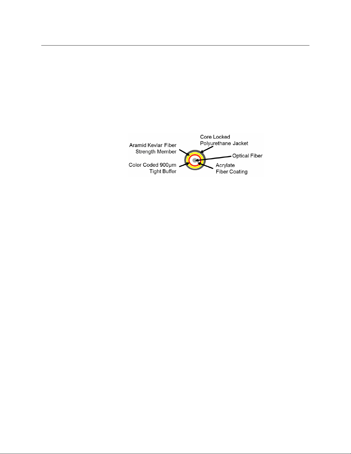
The specific theory and operation of Fiber Optics is beyond the scope of this document, but
you need to be aware of the different types of Fiber Optic Cable and Fiber Optic Cable
Connectors. Most CommLink TR6442i Fiber Optic Intercom Link applications will use Single
Mode Fiber with ST Connectors.
Fig. 2-1: Single Mode Fiber Optic Cable Cross-Section
6
Page 11
Wavelength-Division Multiplexing (WDM)
Fiber optic transmission depends on Wavelength-Division Multiplexing (WDM). With WDM,
a number of optical carrier signals can be carried on a single optical fiber by using different
wavelengths of laser light. The full theory of WDM is beyond the scope of this manual, but it
is important to understand that by using equipment with different WDM factors on either
end of a fiber optic cable, signals can be sent in both directions over that single cable. The
CommLink units use a WDM factor of 1310 nm and a WDM of 1550 nm to provide a
complementary pair.
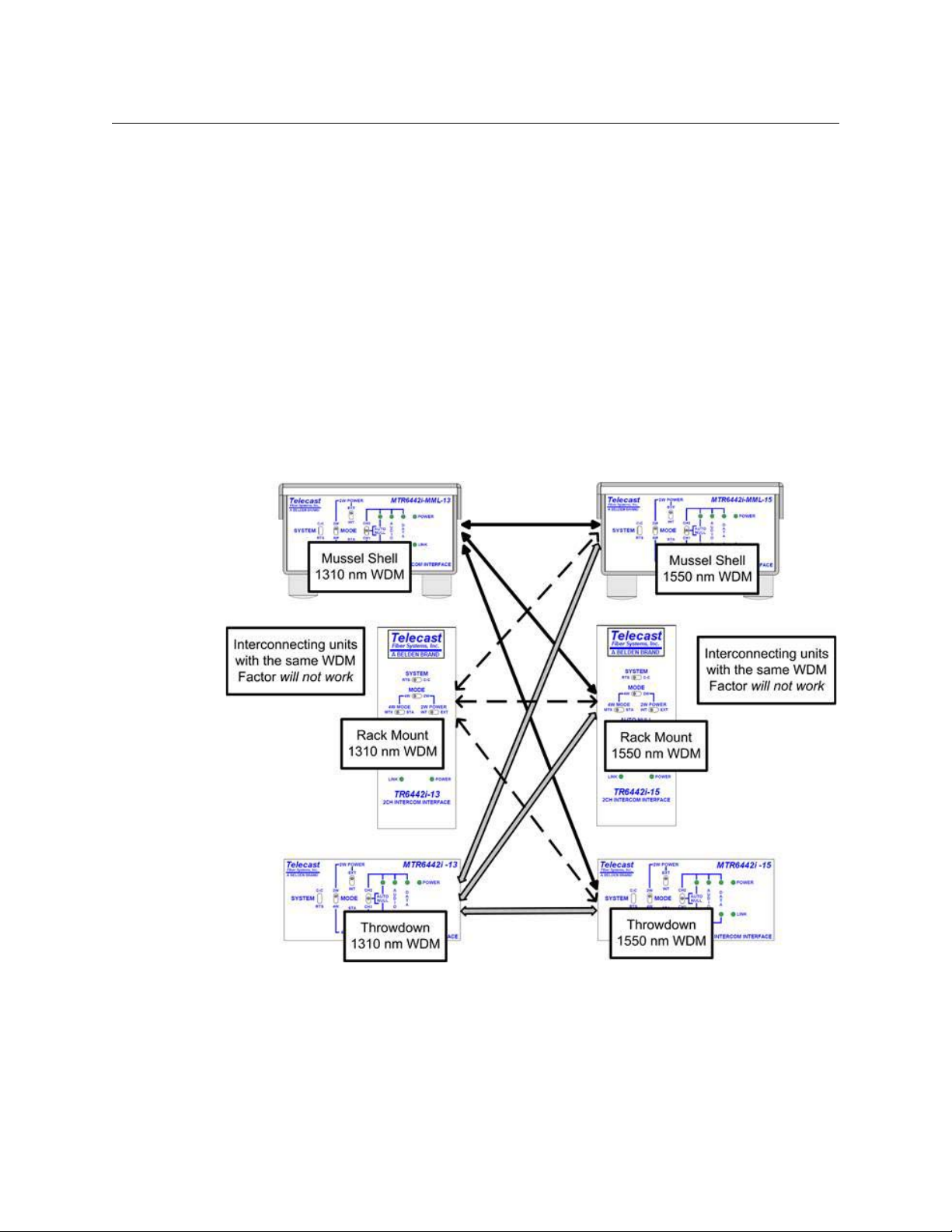
In practice, any CommLink setup requires one unit with a 1310 nm WDM factor and one
unit with a 1550 nm WDM factor. Any 1310 nm unit can be used with any 1550 nm unit
regardless of physical form. Two units with the same WDM factor will not work regardless of
the physical form.
Figure 2-2 displays how any 1310 nm WDM CommLink unit can be paired with any 1550 nm
WDM unit. Select one form factor at 1310 nm and pair the 1310 nm unit with one form
factor at 1550 nm.
CommLink TR6442i
User Guide
Fig. 2-2: Pairing Different WDM Factor CommLink Units
7
Page 12
System Overview
Wavelength-Division Multiplexing (WDM)
Fig. 2-3: CommLink Block Diagram
8
Page 13
CommLink TR6442i
User Guide
CommLink TR6442i Fiber Optic Intercom Link Fiber Optic Intercom Link Components
The three physical types of the CommLink TR6442i Fiber Optic Intercom Link Fiber Optic
Intercom Link work identically. The variations between them lie in their physical
appearance and in how they are powered.
In this section, the "throwdown" version of the CommLink TR6442i Fiber Optic Intercom
Link Fiber Optic Intercom Link is used to illustrate functionality. The variations for the other
two types of CommLink TR6442i Fiber Optic Intercom Link Fiber Optic Intercom Link (Rack
Mount and Mini-Mussel Shell) are explained in later sections. See
TR6442i Fiber Optic Intercom Link in the Viper II Rack on page 39 for information about the
installation of the CommLink TR6442i Fiber Optic Intercom Link rack mount version in the
Viper II rack.
CommLink TR6442i Fiber Optic Intercom Link Fiber Optic Intercom Link Front Panel
Installing the CommLink
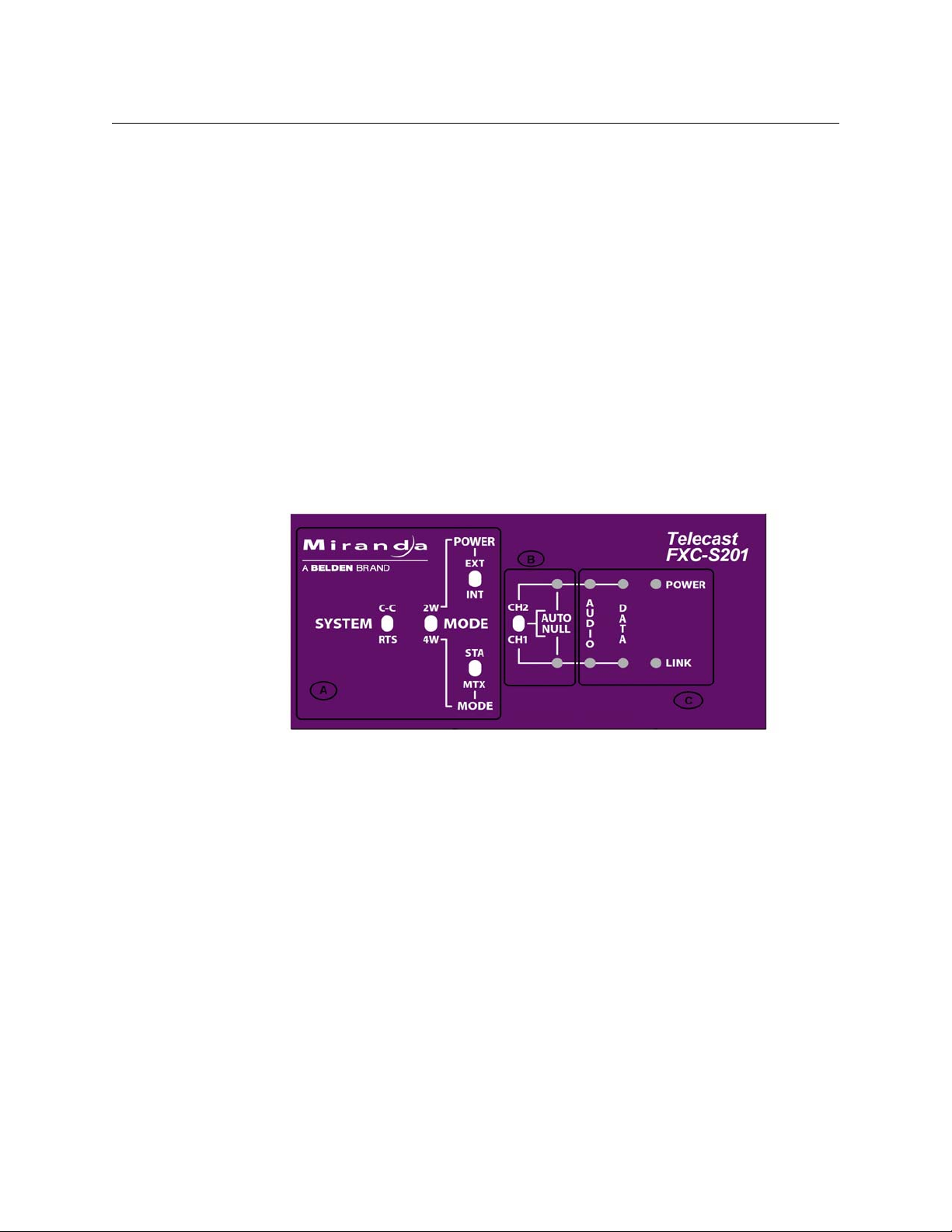
Fig. 2-4: CommLink TR6442i Fiber Optic Intercom Link Throw Down Front Panel
The CommLink TR6442i Fiber Optic Intercom Link has three features:
• Area A: System Configuration Switches
• Area B: Auto Null Control and Indicators
• Area C: System Status Indicators
9
Page 14
System Overview
CommLink TR6442i Fiber Optic Intercom Link Fiber Optic Intercom Link Front Panel
Area A - System Configuration Switches
The four switches in this section allow the configuration of the CommLink TR6442i Fiber
Optic Intercom Link for the particular intercom environment in use. See
CommLink TR6442i Fiber Optic Intercom Link Usage Scenarios on page 22 below on
operation of the CommLink TR6442i Fiber Optic Intercom Link for examples of how these
switches interact.
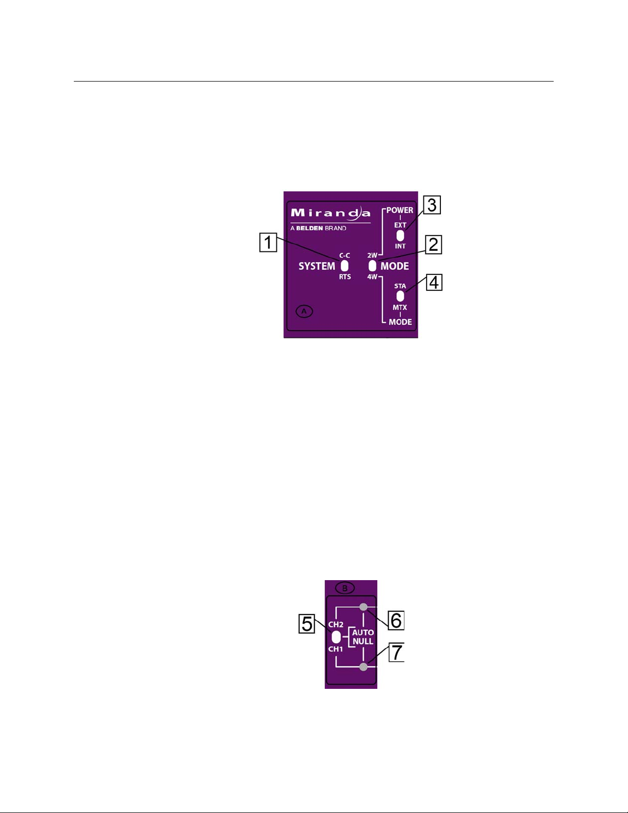
Fig. 2-5: System Configuration switches
Example
• 1: System Switch - sets the CommLink TR6442i Fiber Optic Intercom Link in either RTS
mode or Clear-Com (C-C) mode
• 2: Mode Switch - sets the CommLink TR6442i Fiber Optic Intercom Link in either Two
Wire (2W) or Four Wire (4W) mode
• 3: 2W Power Switch - sets the CommLink TR6442i Fiber Optic Intercom Link power
mode to either externally powered (EXT) or internally powered (INT). This switch is only
operational when the Mode Switch is set to 2W.
• 4: 4W Mode Switch - sets the CommLink TR6442i Fiber Optic Intercom Link to run in
Station (STA) mode or Matrix (MTX) mode. This switch is only operational when the
Mode Switch is in 4W mode.
When connecting two CommLink TR6442i Fiber Optic Intercom Link units via fiber cable
each CommLink TR6442i Fiber Optic Intercom Link unit must be independently set for the
configuration requirements at that CommLink TR6442i Fiber Optic Intercom Link unit.
Area B - Auto Null Operation
10
Fig. 2-6: Auto Null switch and indicator
Please see Using the Auto-Null Function on page 32 below on the Auto Null function.
Page 15
CommLink TR6442i
User Guide
• 5: Auto Null switch: this three-position spring-loaded momentary switch activates the
Auto Null process for either Channel 1 (CH1) or Channel 2 (CH2).
• 6: Channel 1 Auto Null Activity Indicator: blinks Green while the Nulling process
occurs.
• This indicator will be asolid Green to indicate the process is complete and good.
• This indicator will be Red if there was a problem with the null. (see Using the Auto-
Null Function on page 32 on operating the Auto Null feature)
• 7: Channel 2 Auto Null Activity Indicator: behaves the same as the Ch1 Auto Null
activity indicator
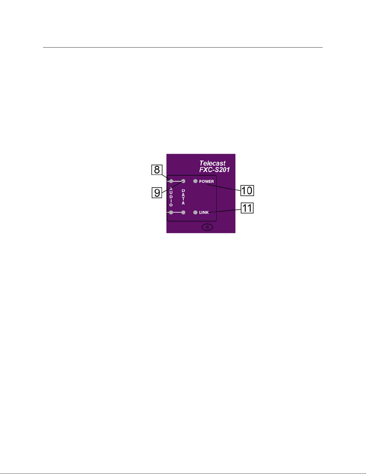
Area C - System Status Indicators
Fig. 2-7: System Status Indicators
• 8: Audio Activity Indicator
• Green when audio activity is below 0 db
• Red when audio activity is above 0 db
•9: Data Activity Indicator
• Green when there is data activity on the particular channel
•10: Power Indicator
• Green indicates power
• 11: Link Status Indicator
• Green indicates link is good
• Red indicates link is bad or non-existent.
11
Page 16
System Overview
CommLink TR6442i Fiber Optic Intercom Link Fiber Optic Intercom Link Back Panel
CommLink TR6442i Fiber Optic Intercom Link Fiber Optic Intercom Link
Back Panel
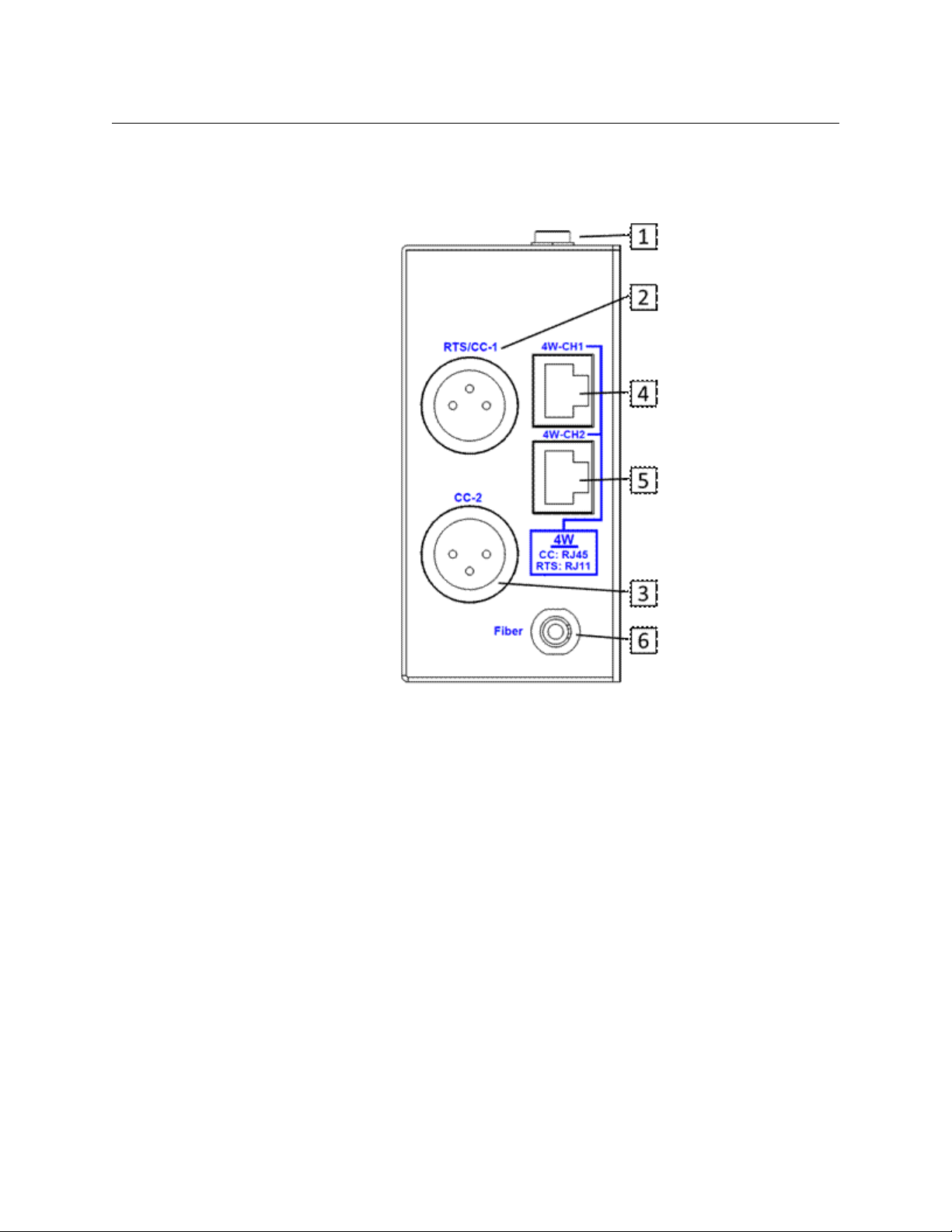
Fig. 2-8: CommLink Throw Down Back Panel
• 1: Power Connector (MTR6442i Throw Down and TR6442i Rack Mount versions only)
This connector takes a 2.5 mm locking power plug. The recommended power unit is
the ADAP-AC-04LC (see
CommLink TR6442i Fiber Optic Intercom Link Power Options
on page 16 for more information regarding CommLink TR6442i Fiber Optic Intercom
Link power options)
• 2: RTS/CC-1 Chassis Mounted XLR Connector - for RTS TW operation or Channel 1 of
Clear-Com two wire operation
• 3: CC-2 Chassis Mounted XLR Connector - for Channel 2 of Clear-Com two wire
operation. Not active when the system is in RTS-TW mode.
Connectors 4 and 5 operate in one of 4 modes, depending on system configuration.
These connectors can be used with RJ45 cables or RJ11 cables. See
CommLink TR6442i
Fiber Optic Intercom Link Matrix and Station Connectors on page 14 for more
information and for wiring information.
• 4: 4W-CH1 Connector - 8 Conductor RJ45/RJ11 connector for Channel 1
• 5: 4W-CH2 Connector - 8 Conductor RJ45/RJ11 connector for Channel 2
• 6: Fiber Connector - ST Connector for Fiber Optic Cable
Read the Using Fiber Optics Guide for information on how to manage and deploy your
fiber optics cabling, safety precautions, tips & tricks, and recommendations for creating
12
Page 17
CommLink TR6442i
User Guide
complex fiber optic networks. You can find a copy of this document on the Support
portal (see
Contact Us on page 37).
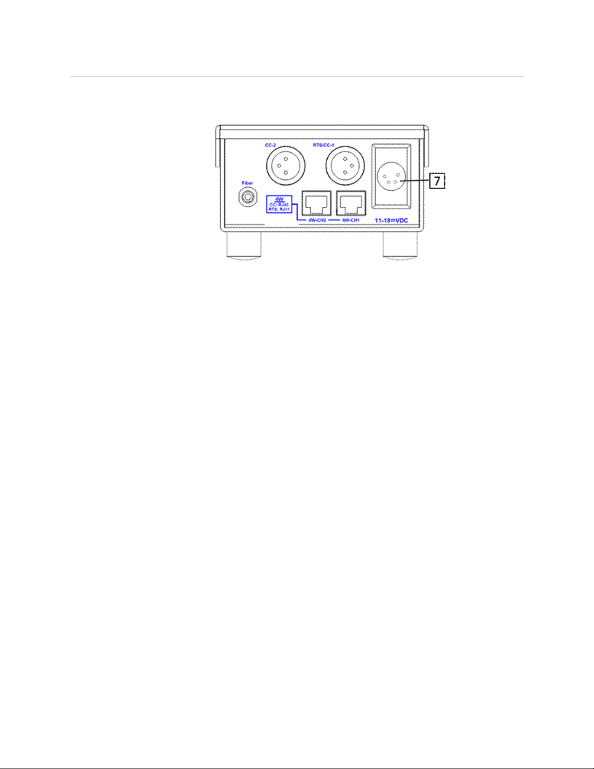
Fig. 2-9: CommLink Mussell Shell Back Panel
• 7: 11-18 VDC Power Connector - for use with the ADAP-AC-04 Power Supply.
This power supply has a 4-pin XLR connector and is used only with the MTR6442i-MML
Mussell Shell configuration of the CommLink TR6442i Fiber Optic Intercom Link. See
CommLink TR6442i Fiber Optic Intercom Link Port State and Power Options on page 17
for wiring information.
13
Page 18
System Overview
CommLink TR6442i Fiber Optic Intercom Link Matrix and Station Connectors
CommLink TR6442i Fiber Optic Intercom Link Matrix and Station
Connectors
Both the RTS and Clear-Com system matrix systems use data wiring to carry intercom audio
and data. Clear-Com systems use an 8-wire "network" cable with RJ45 connectors. RTS
systems use a 6-wire cable with RJ11 connectors similar to standard telephone wiring.
However, telephone wiring will not work as it is only 4-wire.
The CommLink TR6442i Fiber Optic Intercom Link Configuration is shown for each intercom
mode. The switch position is indicated. In all cases, the 4W/2W switch is in the 4W position.
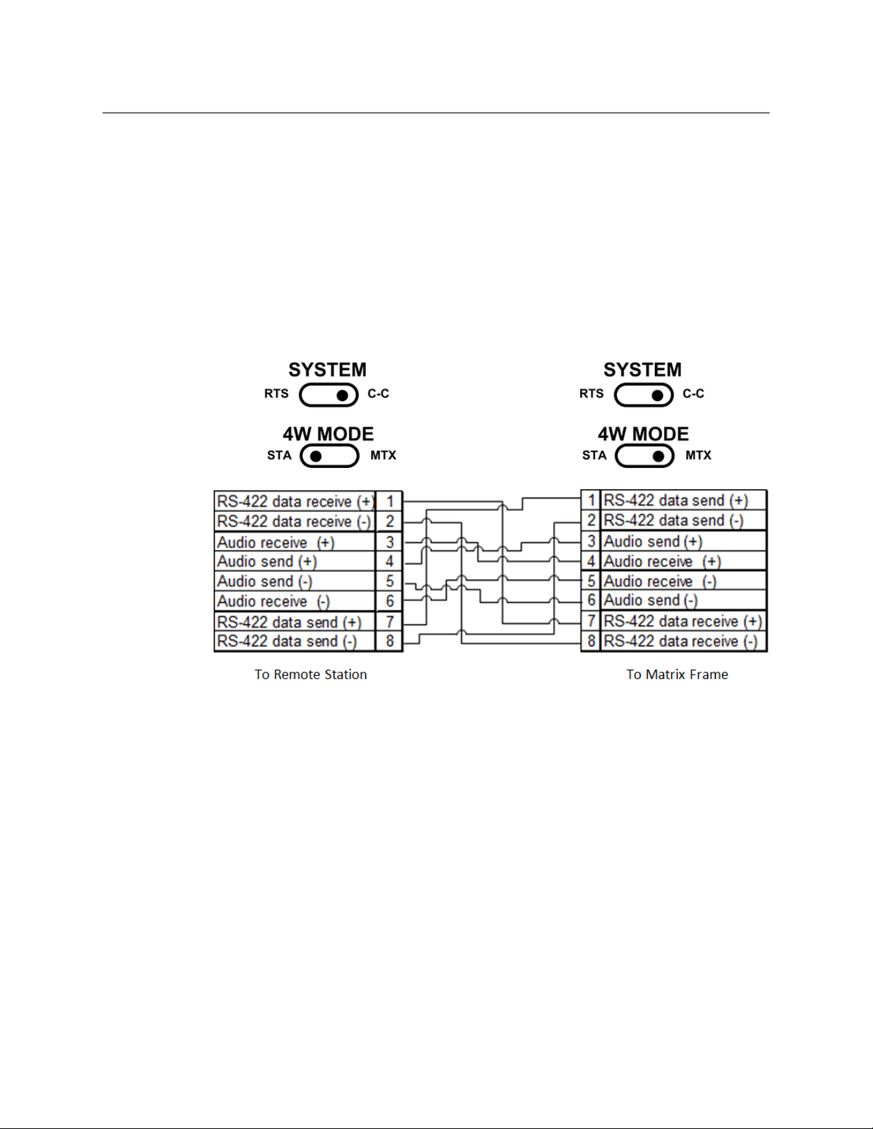
Clear-Com Mode Wiring and Switch Settings
14
Fig. 2-10: Clear-Com Mode Data Cable Wiring
Clear-Com Wiring Pin Outs (RJ45)
•1 to 7
•2 to 8
•3 to 4
•4 to 3
The Clear-Com system utilizes RS422 data.
•5 to 6
•6 to 5
•7 to 1
•8 to 2
Page 19
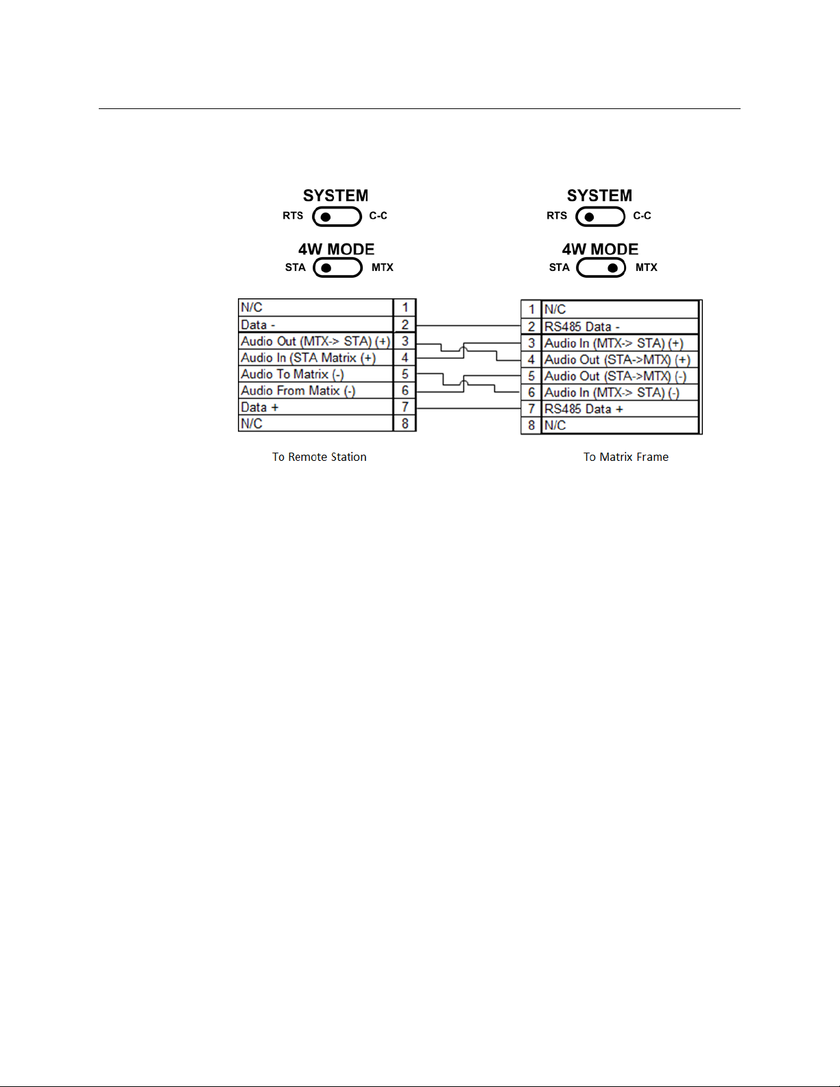
RTS Mode Wiring and Switch Settings
In all cases the 4W/2W switch is in the 4W position.
CommLink TR6442i
User Guide
RTS Wiring Pin Outs RJ11
•1 -- NA
•2 to 2
•3 to 4
•4 to 3
•5 to 6
•6 to 5
•7 to 7
•8 -- NA
Fig. 2-11: RTS Mode Data Cable Wiring
15
Page 20

System Overview
CommLink TR6442i Fiber Optic Intercom Link Power Options
CommLink TR6442i Fiber Optic Intercom Link Power Options
The CommLink TR6442i Fiber Optic Intercom Link Fiber Optic Intercom Link is powered
through an attached external power supply or from power received from the Two-Wire
intercom connection.
The following table shows how each CommLink TR6442i Fiber Optic Intercom Link unit can
be powered:
12 Volt Power
Model Typ e
Supply
MTR6442i-13 or 15 Throw Down ADAP-AC-04LC
with 2.5mm
plug
MTR6442i-MML-13
or 15
TR6442i-13 or 15 Rack Mount in
Mussell Shell ADAP-AC-04
with 4-pin XLR
Powered
Viper II Rack
Unit
through Viper
II frame -
PS5000 power
supply
* 30 Volts is output from the CommLink TR6442i Fiber Optic Intercom Link unit when it has
12V power applied. When no 12V power is applied (2W Power switch is on EXT), the
CommLink TR6442i Fiber Optic Intercom Link unit derives power from the intercom
connection and all Belt-Packs derive power from the Intercom system or from internal
power sources.
When powered by the 12 Volt power supply, the CommLink TR6442i Fiber Optic Intercom
Link will power five intercom belt packs (10 total on the system) or two remote matrix
stations per channel. If the system has self-powered belt packs attached (30V ), and the
external 12 Volt power supply is also attached, the 12 Volt supply takes priority in powering
the CommLink TR6442i Fiber Optic Intercom Link.
30 Volt Power Supply
Can be powered from
Intercom system when
in Two-Wire mode
Can be powered from
Intercom system when
in Two-Wire mode
Can be powered from
Intercom system when
in Two-Wire mode
30 Volt Power Output
to Belt Packs*
30 Volts is provided on
RTS/CC-1 and CC-2
XLR connectors.
30 Volts is provided on
RTS/CC-1 and CC-2
XLR connectors.
30 Volts is provided on
RTS/CC-1 and CC-2
XLR connectors.
16
Page 21

CommLink TR6442i
User Guide
CommLink TR6442i Fiber Optic Intercom Link Port State and Power Options
The CommLink TR6442i Fiber Optic Intercom Link also manages the enabling of ports
depending on the type of power supply and the system mode. The following table shows
the different CommLink TR6442i Fiber Optic Intercom Link states:
Internal 30 Volt
System Mode Power Supply
Supply
Belt Pack Power 4W Ports
2W 30V from Intercom System Disabled Self-powered or from
Intercom System
2W 12 Volt External & Belt-Packs
are powered internally or
from the intercom system
2W 12 Volt External Enabled From CommLink Disabled
4W 12 Volt External Disabled Disabled Enabled
2W to 4W or
4W to 2W
Conversion
12 Volt External Can be used Self-powered or from
Disabled Self-powered or from
Intercom System
Intercom System or
from CommLink
TR6442i Fiber Optic
Intercom Link 30V
supply
Disabled
Disabled
Enabled but
with
RS422/485
data transfer
disabled
Mussel Shell MTR6442i Power Connector - 4 Pin XLR Connector Wiring
Pin Function
1 Ground
2 Unused
3 Unused
4 + Power 12 VDC
This matching connector is from either an ADAP-AC-04 or a customer 12VDC power
supply.
17
Page 22

System Overview
Fiber Part Number ADAP-AC-04
Supplied with 4PIN XLR/A4F connector for
power plug on Mussell Shell unit
Fiber Part Number ADAP-AC-04LC
Supplied with 2.5 MM plug for power jack on
Throw Down unit
Fiber ADAP Power Supplies
Fiber ADAP Power Supplies
18
Fig. 2-12: Power Supplies
Page 23

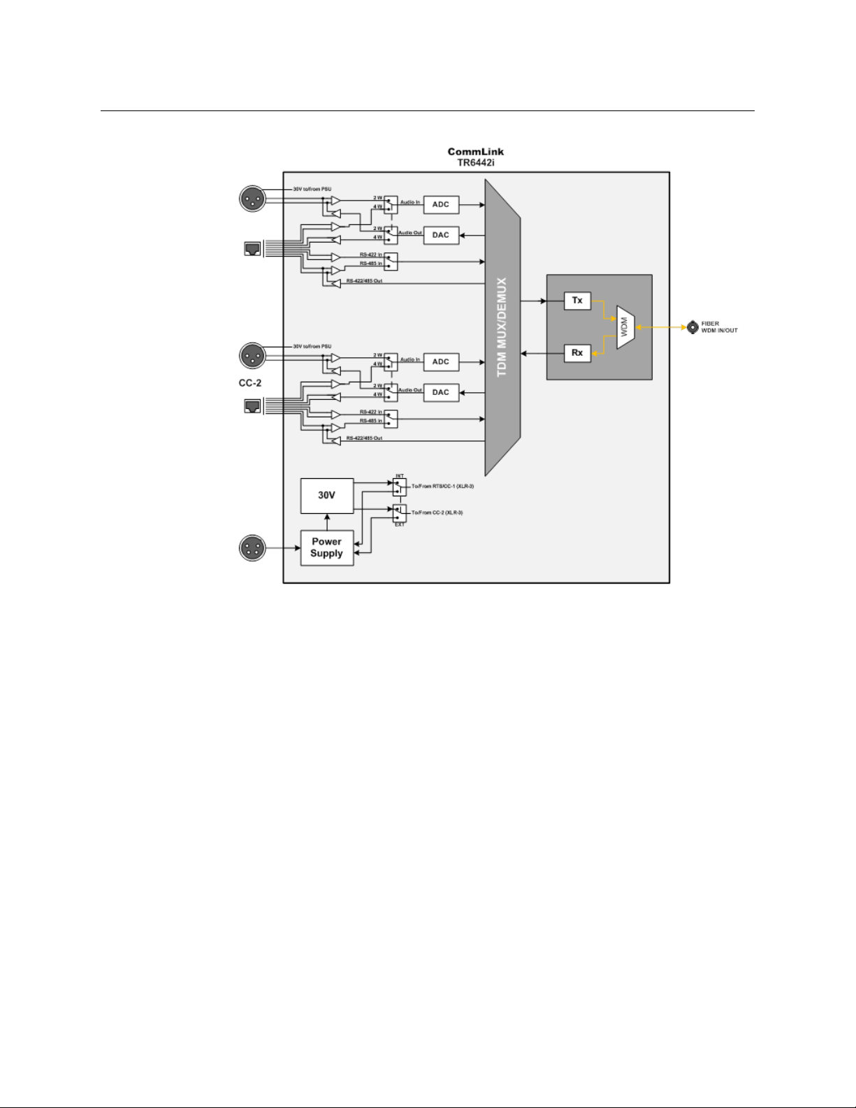
Block Diagram
CommLink TR6442i
User Guide
Fig. 2-13: CommLink TR6442i Functional Block Diagram
19
Page 24

System Overview
Block Diagram
20
Page 25

Setting Up the CommLink TR6442i
This chapter explains how to set up and configure the CommLink TR6442i Fiber Optic
Intercom Link system.
About Setting up the CommLink TR6442i . . . . . . . . . . . . . . . . . . . . . . . . . . . . . . . . . . . . . . . . . . . . . 22
CommLink Physical Configurations . . . . . . . . . . . . . . . . . . . . . . . . . . . . . . . . . . . . . . . . . . . . . . . . . . . 27
CommLink TR6442i Fiber Optic Intercom Link Switch Configuration . . . . . . . . . . . . . . . . . . . 29
21
Page 26

Setting Up the CommLink TR6442i
About Setting up the CommLink TR6442i
About Setting up the CommLink TR6442i
Use of the CommLink TR6442i Fiber Optic Intercom Link system first requires the setup and
connection of the Intercom System and the CommLink TR6442i Fiber Optic Intercom Link
Link units. The second step is the proper configuration or setting of switches on the
CommLink TR6442i Fiber Optic Intercom Link front panel. If two-wire systems are in use, the
Auto Null function should be employed.
Each system setup is based on the appropriate mix of the three physical types of the
CommLink TR6442i Fiber Optic Intercom Link. Depending on your particular operation the
combination of units may be all the same physical type or a mix and match. Whatever the
physical configuration of the units, they must operate in pairs of 1310mm WDM and
1550mm WDM units. It makes no difference where the WDM units are placed in the system.
If the CommLink TR6442i Fiber Optic Intercom Link is being used locally to convert
between intercom system types, either WDM type can be used
Example CommLink TR6442i Fiber Optic Intercom Link Usage Scenarios
Five usage configurations are illustrated:
• Connecting a Two Channel Base System with Remote Belt Packs
• Connecting a Matrix Frame System with Two Remote Matrix Stations
• Connecting a Matrix Frame with Remote Belt Packs
• Connecting Two Matrix Stations System with a Matrix Frame with Video Multiplexed on
to a Multi-Strand Fiber Cable (This is an example of "hybrid" use with the CommLink
TR6442i Fiber Optic Intercom Link)
• Converting a Two Channel System to work with a Matrix Frame
Connecting a Two Channel Base System with Remote Belt Packs
Fig. 3-1: Connecting a Two Channel Base System with Remote Belt Packs
22
Page 27
CommLink TR6442i
User Guide
Connect the Two-Channel Two-Wire Intercom System (1) and CommLink TR6442i Fiber
Optic Intercom Link Unit "A" (2). In this example it is assumed that the CommLink TR6442i
Fiber Optic Intercom Link is powered from the intercom. Run a Single Strand Fiber Cable
(3) between CommLink TR6442i Fiber Optic Intercom Link Unit "B" (4) and power the
CommLink TR6442i Fiber Optic Intercom Link using the appropriate power supply (5).
Connect your intercom Belt Packs in normal daisy chain fashion to the CommLink TR6442i
Fiber Optic Intercom Link. The number of Belt Packs will depend on whether they are selfpowered or are powered by the CommLink TR6442i Fiber Optic Intercom Link. When
powered by the CommLink TR6442i Fiber Optic Intercom Link you can expect 5 units to
work per channel.
Remember that CommLink TR6442i Fiber Optic Intercom Link "A" must have a WDM factor
different from CommLink TR6442i Fiber Optic Intercom Link "B." You must use a WDM
@1550nm unit at one end of the fiber cable and a WDM@1310 at the other end of the fiber
cable.
In this example two Mussel Shell versions of the CommLink TR6442i Fiber Optic Intercom
Link are used. It makes no difference which of the three physical versions is used so long as
the WDM factors are different as described above.
CommLink Unit System Switch Mode Switch 4W Switch 2W Power Switch
#A in drawing Match Intercom 2W NA EXT
#B in drawing Match Intercom 2W NA INT
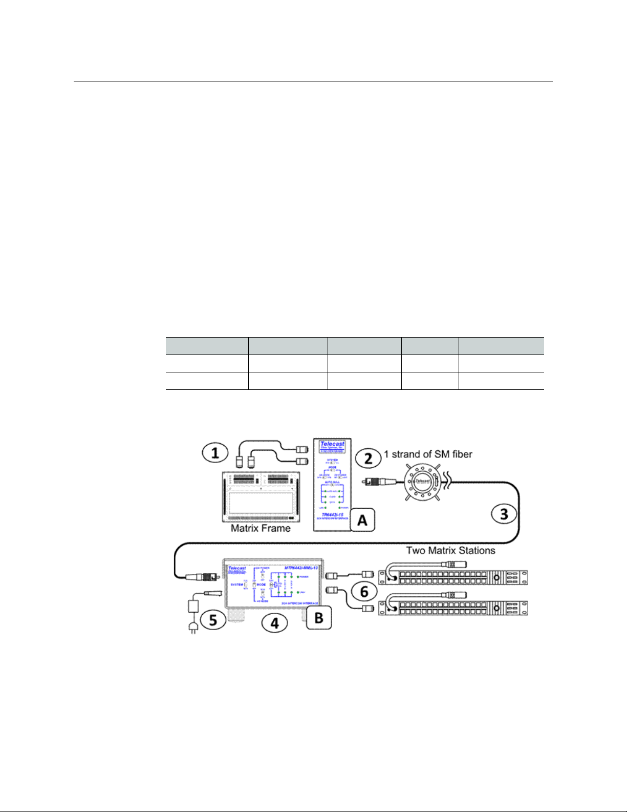
Connecting a Matrix Frame System with Two Remote Matrix Stations
Fig. 3-2: Connecting a Matrix Frame System with Two Remote Matrix Stations
Connect the Intercom Matrix (1) and CommLink TR6442i Fiber Optic Intercom Link Unit "A"
(2) In this case it is assumed the CommLink TR6442i Fiber Optic Intercom Link is a rack
mount unit and is powered from the Viper II frame.* Run a Single Strand Fiber Cable (3)
between CommLink TR6442i Fiber Optic Intercom Link Unit "B" (4) and power the
CommLink TR6442i Fiber Optic Intercom Link using the appropriate power supply (5).
23
Page 28
Setting Up the CommLink TR6442i
Connecting a Matrix Frame with Remote Belt Packs
Connect your two intercom Matrix Stations (6) and provide power locally. Remember that
CommLink TR6442i Fiber Optic Intercom Link "A" must have a WDM factor different from
CommLink TR6442i Fiber Optic Intercom Link "B." You must use a WDM @1550nm unit at
one end of the fiber cable and a WDM@1310 at the other end of the fiber cable.
* If using a Throw Down CommLink TR6442i Fiber Optic Intercom Link it would need to be
powered from the ADAP-AC-04LC power supply unit
CommLink Unit System Switch Mode Switch 4W Switch 2W Power Switch
#A in drawing Match Intercom 4W MTX NA
#B in drawing Match Intercom 4W STA NA
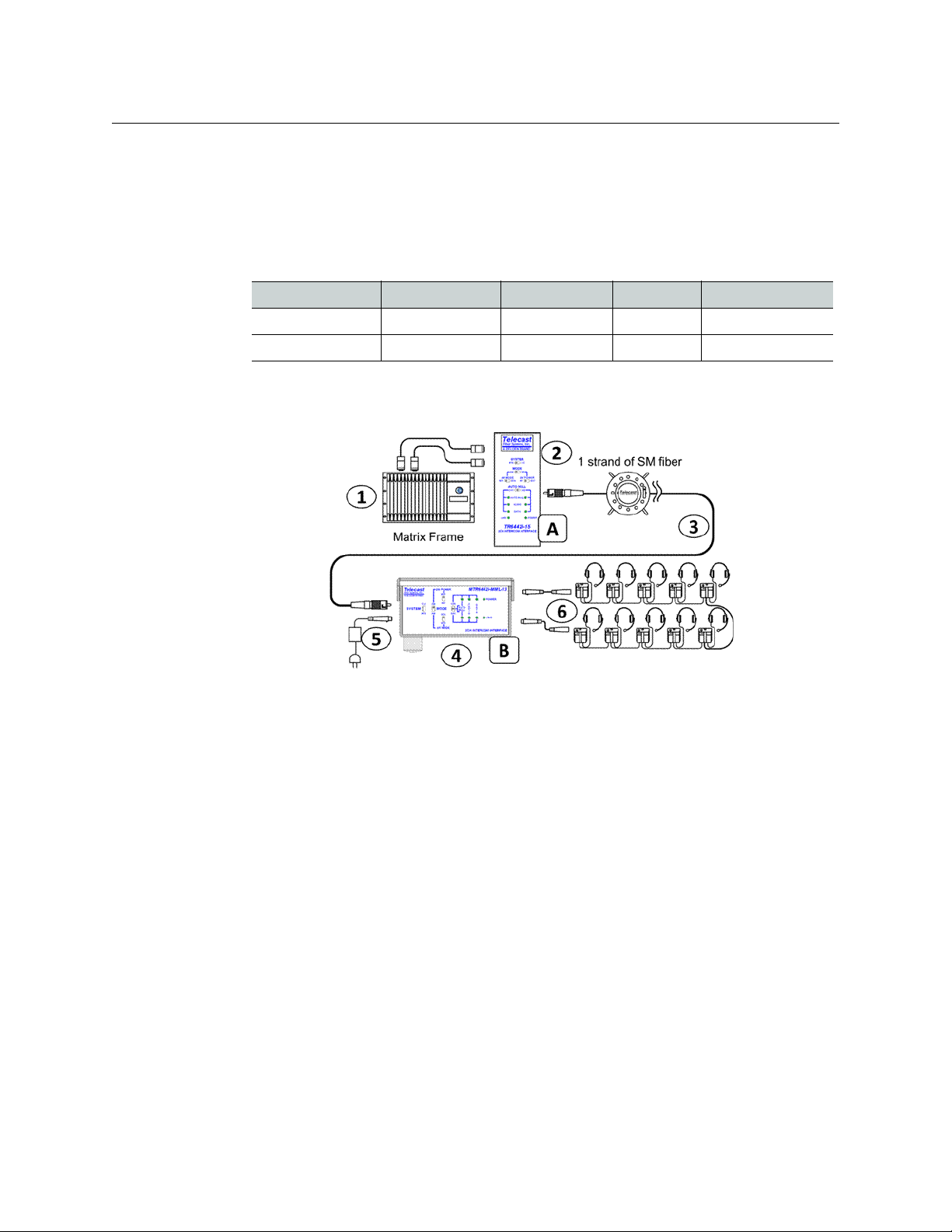
Connecting a Matrix Frame with Remote Belt Packs
Fig. 3-3: Connecting a Matrix Frame with Remote Belt Packs
Connect the Intercom Matrix (1) and CommLink TR6442i Fiber Optic Intercom Link Unit "A"
(2) In this case it is assumed the CommLink TR6442i Fiber Optic Intercom Link is a rack
mount unit and is powered from the Viper II frame.* Run a Single Strand Fiber Cable (3)
between CommLink TR6442i Fiber Optic Intercom Link Unit "B" (4) and power the
CommLink TR6442i Fiber Optic Intercom Link using the appropriate power supply (5).
Connect your intercom Belt Packs in normal daisy chain fashion to the CommLink TR6442i
Fiber Optic Intercom Link. The number of Belt Packs will depend on whether they are selfpowered or are powered by the CommLink TR6442i Fiber Optic Intercom Link. When
powered by the CommLink TR6442i Fiber Optic Intercom Link you can expect 5 units to
work per channel depending on cable runs
Remember that CommLink TR6442i Fiber Optic Intercom Link "A" must have a WDM factor
different from CommLink TR6442i Fiber Optic Intercom Link "B." You must use a WDM
@1550nm unit at one end of the fiber cable and a WDM@1310 at the other end of the fiber
cable.
* If using a Throw Down CommLink TR6442i Fiber Optic Intercom Link it would need to be
powered from the ADAP-AC-04LC power supply unit
24
Page 29

CommLink Unit System Switch Mode Switch 4W Switch 2W Power Switch
#A in drawing Match Intercom 4W MTX NA
#B in drawing Match Intercom 2W NA INT
Connecting a Two Matrix Stations System
CommLink TR6442i
User Guide
Fig. 3-4: Connecting Two Matrix Stations System with a Matrix Frame plus Video Multiplexed on the
Multi-Strand Fiber Cable
This usage scenario demonstrates the flexibility provided by Grass Valley products. In this
case Multi-Strand Fiber Cable with MX Connectors is used in place of Single Strand Fiber
Cable. With the addition of the Break Out cable MXRR-4-08 Fiber optic signals can be sent to
multiple locations. Here a Grass Valley Rattler Mini HD/SDI Transmitter and Receiver are
used to transmit HD video along the same Fiber Cable as the Intercom Link. A wide variety
of set-ups is possible using different components. Please consult your Grass Valley dealer
for more information.
The example calls for you to connect the Matrix Stations (1) and CommLink TR6442i Fiber
Optic Intercom Link Unit "A" (2). In this case it is assumed the CommLink TR6442i Fiber Optic
Intercom Link is a rack mount unit and is powered from the Viper II frame.* Connect the
CommLink TR6442i Fiber Optic Intercom Link Unit to the Break-Out Cable (3) and then
connect the Break-Out cable to the Multi-Strand Fiber Cable (5). Connect the Rattler
Receive Unit RRX 1679 (4) to your HD Video Display and to the Break Out Cable (3).
Connect the Fiber Cable (5) to a Break Out Cable (6) at the other end. The Break Out Cable
then connects to CommLink TR6442i Fiber Optic Intercom Link Unit "B" (8) and to the
Rattler Transmit Unit RTX 1660 (7). The Rattler is connected to your HD Video Source and
CommLink TR6442i Fiber Optic Intercom Link is connected to the Intercom Matrix Frame
(9).
25
Page 30

Setting Up the CommLink TR6442i
Converting a Two Channel System to work with a Matrix Frame
Converting a Two Channel System to work with a Matrix Frame
Fig. 3-5: Converting a Two Channel System to work with a Matrix Frame
Connect the Two-Channel Two-Wire Intercom System (1) and CommLink TR6442i Fiber
Optic Intercom Link Unit (2). In this example a Mussell Shell version is used. Power the
CommLink TR6442i Fiber Optic Intercom Link using the appropriate power supply (3).
Connect the Intercom Matrix (4). The WDM factor of the CommLink TR6442i Fiber Optic
Intercom Link is not relevant in this scenario.
In this example a Mussel Shell version of the CommLink TR6442i Fiber Optic Intercom Link
is used. It makes no difference which of the three physical versions of the CommLink
TR6442i Fiber Optic Intercom Link is used.
The System Switches should be set as follows:
• SYSTEM - Set for your Two Channel System - ClearCom (CC) or RTS
• MODE - Set to 2W
• 2W POWER - Set for your CommLink Unit
26
Page 31

CommLink Physical Configurations
MTR6442i-MML
MiniMussel Shell Enclosure for Harsh Environments
MTR6442i
"Throw Down"
TR6442i
Viper II Rack Mount
The CommLink™ TR6442i Intercom Link comes in three physical configurations each supplied
in a 1310mm unit and a 1550 nm unit. Please see
ordering information.
CommLink TR6442i
User Guide
Ordering Information on page 4 for
Fig. 3-6: CommLink TR6442i Fiber Optic Intercom Link Physical Configurations
All variations of the CommLink™ TR6442i Intercom Link work in the same way. The only
difference is in the method in which they are powered and whether they are a 1310mm or a
1550mm unit.
The system provides flexibility in the types of intercom systems that can be used in that the
system can link one type of party line system to another type of party line system, a matrix
frame to two key panels, or act as a two-wire to four wire hybrid adaptor via fiber or as a
standalone local unit. Each of these operating modes is explained in detail later in this
document.
TWO-WIRE PARTYLINE MODE
Plug two channels of Clear-Com® PL (two XLRs) or RTS® TW (one XLR) into each CommLink
module and connect them with a fiber cable. The system will "translate" between two
systems so that you can have Clear-Com® at one end and RTS® at the other. It also translates
the call lights.
27
Page 32

Setting Up the CommLink TR6442i
CommLink Physical Configurations
ADVANCED DSP AUTO-NULLING
Once the two-party system is connected, a toggle of the AUTO NULL switch provides a digital
system null of the two-wire system, no matter what the load, without the need for manual
adjustments.
BELT PACK POWER
Each CommLink™ module can be powered from the Party line intercom circuit without an
external power supply, like a belt pack. Alternately, with a 12VDC power source, the
CommLink unit can act as a Party line power supply, providing enough 30VDC current to
support approximately ten belt packs.
FOUR-WIRE MATRIX MODE
The system links a MatrixPlus/Eclipse (Clear-Com®) or Adam (RTS®) family matrix frame and
two of the system's key panels over a fiber strand. All of the key panel functionality is
supported, including displays, controls, and communications to the matrix frame.
HYBRID MODE
The CommLink system can be used to connect a matrix frame in a control room or truck with
two party line channels in the venue, without the need for a separate hybrid adaptor.
A single CommLink unit can also act as a standalone digital system interface/system-tosystem adapter, utilizing the digital auto-nulling system. Connect two-wire intercom
systems to legacy fiber systems, two-way radios, satellite links, TV cameras, and other
communications devices with 4-wire circuits.
28
Page 33

CommLink TR6442i
User Guide
CommLink TR6442i Fiber Optic Intercom Link Switch Configuration
The following decision tree traces the setting of the CommLink TR6442i Fiber Optic
Intercom Link configuration switches.
• Set the System mode - Clear-Com (CC) or RTS
• Decide if you are operating in 2W or 4W
• If in 2W set your power to External (EXT) or Internal (INT) - this decides between using
the power from the intercom system or Belt Packs (EXT) or providing internal power
from the CommLink TR6442i Fiber Optic Intercom Link with the 12 Volt power supply
(INT)
• If in 4W set the switch depending on whether you have an Intercom Matrix Station
(STA) or Matrix (MTX) attached to the CommLink TR6442i Fiber Optic Intercom Link
Fig. 3-7: Configuration Switch Decision Tree
29
Page 34

Setting Up the CommLink TR6442i
CommLink TR6442i Fiber Optic Intercom Link Switch Configuration
30
Page 35

CommLink TR6442i Operation
This chapter describes in the operation of CommLink TR6442i Fiber Optic Intercom Link.
Please keep in mind that once the system is properly set up and configured there is very
little to do during normal operation.
Using the Auto-Null Function . . . . . . . . . . . . . . . . . . . . . . . . . . . . . . . . . . . . . . . . . . . . . . . . . . . . . . . . . 32
Best Practices . . . . . . . . . . . . . . . . . . . . . . . . . . . . . . . . . . . . . . . . . . . . . . . . . . . . . . . . . . . . . . . . . . . . . . . . 33
Troubleshooting . . . . . . . . . . . . . . . . . . . . . . . . . . . . . . . . . . . . . . . . . . . . . . . . . . . . . . . . . . . . . . . . . . . . . 33
31
Page 36

CommLink TR6442i Operation
Using the Auto-Null Function
Using the Auto-Null Function
The Auto-Null function is used only with CommLink TR6442i Fiber Optic Intercom Link units
that are connected to Two-Wire system. Auto Null has no purpose with a Four Wire system.
To use the Auto-Null Function
1 Before starting the Auto-Null process, ensure the following:
• A: All headsets are connected
• B: Headsets are not being worn by any operators
• C: Headset microphones are off
2 To Auto Null Channel 1 (CH1), hold the Auto Null switch (A) in the direction of CH1.
The system will generate a tone and the indicator (B) will blink green while the Nulling
process occurs. This should take about 7.5 seconds.
3 Once the Auto Null process is complete, the tone will stop and the indicator will glow
green.
This indicator will be red if there was a problem with the null. This can occur if any of
the items in Step 1 are not followed.
4 Once you troubleshoot the Null problem, perform Steps 1-3 again.
5 For Channel 2 (CH2), hold the Auto Null switch (A) in the direction of CH2. Steps 2 and 3
will then follow with the CH2 indicator being active (C).
6 After completing the Auto-Null process, check that side-tone operation and overall
intercom performance on each intercom channel is correct.
32
Page 37

Best Practices
• Take every precaution to reduce the risk of damaging your eyes when handling the
• Protect the Fiber Optic Cable and the Fiber Optic Connectors. Always keep these
•Read Best Practices on page 33 on planning the Fiber Run.
• Once the system is set up and running, carefully monitor the Link strength indicators at
• If introducing new equipment (intercom units, additional Belt-Packs, etc.) or new
• Be as careful during System tear down as during System setup.
CommLink TR6442i
User Guide
equipment.
capped unless there are being connected.
either of the CommLink TR6442i Fiber Optic Intercom Link units. Because the system is
digital, the Signal Strength either meets or exceeds the operational requirements.
When theSignal Strength is no longer strong enough, the signal stops.
operators, be sure to do a comprehensive, realistic test run. A hands-on approach is the
best way to understand how the system should work will and what to do to ensure
proper operation.
Troubleshooting
Troubleshooting any technical issues with the CommLink TR6442i Fiber Optic Intercom Link
Fiber Optic Intercom Link System is similar to any piece of television production gear, with
the exception of the core Fiber Optic technology.
The following is a list of checks to keep in mind:
• During power-up of the CommLink TR6442i Fiber Optic Intercom Link, the Auto Null
indicators will turn Green, then Red, and then OFF. This indicates that these LEDs are
working properly. These are the only indicators tested on power up.
• The Auto Null indicators will blink RED if any of the CommLink TR6442i Fiber Optic
Intercom Link operating power levels are out of specification. This error condition will
not likely affect operation, but it should be addressed as soon as possible. This error
may require contacting Grass Valley Support (see
• Check all your cables forany broken connections or bad connectors.
• Check that your Power Supplies are working.
• If there is a power problem, check the fuses.
• If you cannot resolve the problem in the field, contact Grass Valley Fiber support (see
Contact Us on page 37)
Contact Us on page 37).
33
Page 38

CommLink TR6442i Operation
Troubleshooting
34
Page 39

Specifications
Intercom
Number or intercom channels................................................................................................. 2
2-Wire (TW/PL)
Interface:...........................................................................................Clear-Com PL: XLR3M x 2
..........................................................................................................................RTS TW: XLR3M x 1
Max Level.......................................................... 2VP-P, @ 1KHz (equiv. to +18dBu in 4W)‡
Dyn. Range...................................................................................>85dB, ref. 2VP-P @ 1KHz ‡
Freq. Response ........................................................+.1/-3dB, 70Hz to 22kHz, ref. 2VP-P ‡
THD+N................................................................................................................. <.1% @ 2VP-P ‡
I/O Impedance (100Hz to 20KHz)......
Termination engaged (internal power) ..................................................... 220? ±10%
Termination dis-engaged (external power)........................................................ ?10K?
Nulling: ................................................................................................................ Automatic DSP
‡properly terminated (internal or external)
4-Wire (4W) Ports
Interface ................................................................ Clear-Com MatrixPlus/Eclipse: RJ45 x 2
..............................................................................................RTS Adam/Cronus/Zeus: RJ11 x 2
Maximum Level (I/O, Unity Gain) ............................................................................+18dBu
Dynamic Range ....................................................................................... >85dB, ref. +18dBu
Frequency Response.................................................... +.1/-3dB, 35Hz-22kHz, ref. 0dBu
THD+N............................................................................................ <.05% @ +17dBu @ 1KHz
Input Impedance. .............................................................................................10k? balanced
Output Impedance.... ........................................................................................30? balanced
Data: . ....................................................................................Clear-Com: RS422, RTS: RS485
Crosstalk: . .......................................................................................................................... >85dB
Electro-Optical
Operating Wavelength, standard .......1310/1550 nm (Wave Division Multiplexed)
Nominal Optical Loss Budget Values
TX Laser output power............................................................................................-7 dBm
RX Sensitivity, HD/SDI............................................................................................-22 dBm
Link/Distance Limit* ............................................................... 15dB optical loss (? 30Km*)
Fiber Compatibility... ............................................................................................ Single Mode
Optical Connector .....................................................................................................................ST
*Maximum cable length varies due to optical cable quality, dirt/dust/contamination on
connectors, and the number of in-line connectors.
35
Page 40

Specifications
Mechanical/Environmental
Dimensions (HxWxL)
Rack Mount....................................................................................................... 5" x 2" x 10"
Throw Down......................................................................................................4" x 2" x 10"
Mini-Mussel (without feet)........................................................................... 2" x 4" x 10"
Weight
Rack Mount/Throwdown......................................................................................1.375 lb
MiniMussel......................................................................................................................2.8 lb
Power Consumption
2W with Local Power ...................................................................... 3 watts@10-18VDC
Powered from 2W System............................................................. 6 watts@10-18VDC
4W System .......................................................................................... 3 watts@10-18VDC
Temperature Range ............................................................................................. -25° to +55°C
Humidity Range .................................................................. 0 to 95% RH, Non-condensing
Compliance
Laser Safety...............................................................................Class 1 Laser 21 CFR 1040.10
EMI/RFI..................................................................................................................IEC/EN 60825-1
RoHS
36
Page 41

Grass Valley Technical Support
For technical assistance, please contact the Grass Valley Technical Support center nearest
you:
Contact Us
Americas
Office hours: 9:00 a.m. – 9:00 p.m. (EST)
Telephone: 1-800-224-7882
Fax: +1 514 335 1614
E-mail: support@miranda.com
Europe, Middle East, Africa, UK
Office hours: 9:00 a.m. – 6:00 p.m. (GMT)
Telephone: +44 118 952 3444
Fax: +44 118 952 3401
E-mail: eurotech@miranda.com
France
Office hours: 9:00 a.m. – 5:00 p.m. (GMT+1)
Telephone: +33 1 55 86 87 88
Fax: +33 1 55 86 00 29
E-mail: eurotech@miranda.com
Corporate Head Office
Asia
Office hours: 9:00 a.m. – 6:00 p.m. (GMT+8)
Telephone: +852 2539 6987
Fax: +852 2539 0804
E-mail: asiatech@miranda.com
China
Office hours: 9:00 a.m. – 6:00 p.m. (GMT+8)
Telephone: +86 10 5873 1814
E-mail: asiatech@miranda.com
Malaysia
Telephone: +60 3 2247 1808
EMERGENCY After Hours (Global)
Toll Free: 1-800-224-7882 (US and Canada)
Telephone: +1 514 333 1772
Grass Valley
3499 Douglas-B.-Floreani
St-Laurent, Quebec H4S 2C6
Canada
Telephone: +1 514 333 1772
Fax: +1 514 333 9828
Web: www.miranda.com
Page 42

CommLink TR6442i Installation Items
This appendix explains how to mount CommLink TR6442i in a rack and how to convert a
Rack Mount Unit for use.
Installing the CommLink TR6442i Fiber Optic Intercom Link in the Viper II Rack . . . . . . . . 39
Converting the TR6442i Viper II Rack Mount Unit . . . . . . . . . . . . . . . . . . . . . . . . . . . . . . . . . . . . . . 40
38
Page 43
Installing the CommLink TR6442i Fiber Optic Intercom Link in the Viper II Rack
Installing the CommLink TR6442i Fiber Optic Intercom Link in the
Viper II Rack
Note: Much of this section is adapted from the Viper II - V2Frame User
Guide which is available at
consult this manual for complete information regarding the use and
operation of the Viper II V2 Frame.
The CommLink TR6442i Fiber Optic Intercom Link 13 or 15 rack mount unit is a standard
Viper II module. When installing or removing modules, takespecial care to ensure that no
damage occurs as a result of an improperly inserted module as the pins are of a very fine
pitch and can easily be bent.
If pins do become bent, contact Grass Valley for an RMA number.Do NOT attempt to repair
bent pins as failure to properly align the backplane will result in additional bent pins.
Carefully align the module in the top and bottom guides and slowly insert it into place. As
the rear end of the module nears the rear of the frame, it will hit a riser-plate that serves to
lift the module so that the power connectors will properly come together and seat.
You should be able to sense the plate as you insert the module and sense the female power
connector on the module make smooth contact with the male power plug in the frame.
Any attempts to force the module into the frame are likely to result in bent pins.
http://www.miranda.com/support. Please
39
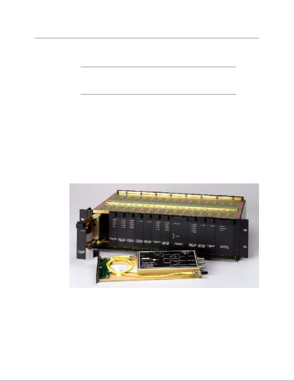
Fig. A-1: Viper II - V2 Frame
The CommLink TR6442i Fiber Optic Intercom Link Rack Mount unit can go into any Viper II
frame slot.
Page 44

Converting the TR6442i Viper II Rack Mount Unit
The CommLink TR6442i Fiber Optic Intercom Link Rack Mount version can be converted to
a MTR 6442i Throw Down version of the CommLink. The Throw Down unit can also be
converted to a Rack Mount kit. The conversion of a Rack Mount unit requires a TDK-TR6442i
kit and the conversion of a Throw Down unit requires an RMK-TR6442i kit. The kit consists of
a replacement front plate and rear plate. Make sure you order the -13 or -15 version of the
kit to match your existing CommLink unit.
Fig. A-2: 2CH Intercom Interfaces
The CommLink TR6442i Fiber Optic Intercom Link Rack Mount Unit can be converted to a
CommLink MTR6442i Throw Down Unit.
CommLink TR6442i
User Guide
Fig. A-3: Side view of the CommLink Units
The conversion can be performed by a qualified end-user who is comfortable working with
delicate multi-pin connectors and can work in a static-free environment. An experienced
Grass Valley technician can accomplish this conversion in about 15 minutes,but if you
decide to perform the conversion yourself, you should budget about an hour to complete
this task.Make sure you have time to fully test the unit prior to using in a production
environment.
You will need the following tools:
• a medium Phillips head screwdriver
• a wrench to loosen and re-install an ST Fiber Barrel
• a container to temporarily hold a number of screws
• a clean static-free work space
The conversion of a Throw Down unit is essentially the same using the RMK-TR6442i kit.
40
Page 45

Converting the TR6442i Viper II Rack Mount Unit
To convert a CommLink Rack Mount Unit to a Throw Down Unit
Please walk through all of the steps prior to beginning the disassembly of the Rack Mount
unit. Be sure totake the time to understand each step and be careful when disconnecting
and reconnecting the multi-pin connectors.
1 Disconnect all cables and power from the unit and place it on your work surface.
Remove three screws from the top of the unit and three screws from the side of the unit
with the power connector. Make sure to retain the screws for re-use later.
2 On the side opposite the power connector, remove the three remaining cover screws
and retain the screws for re-use later. After removing all of the cover screws, lift off the
cover being careful not to pull the power connection.
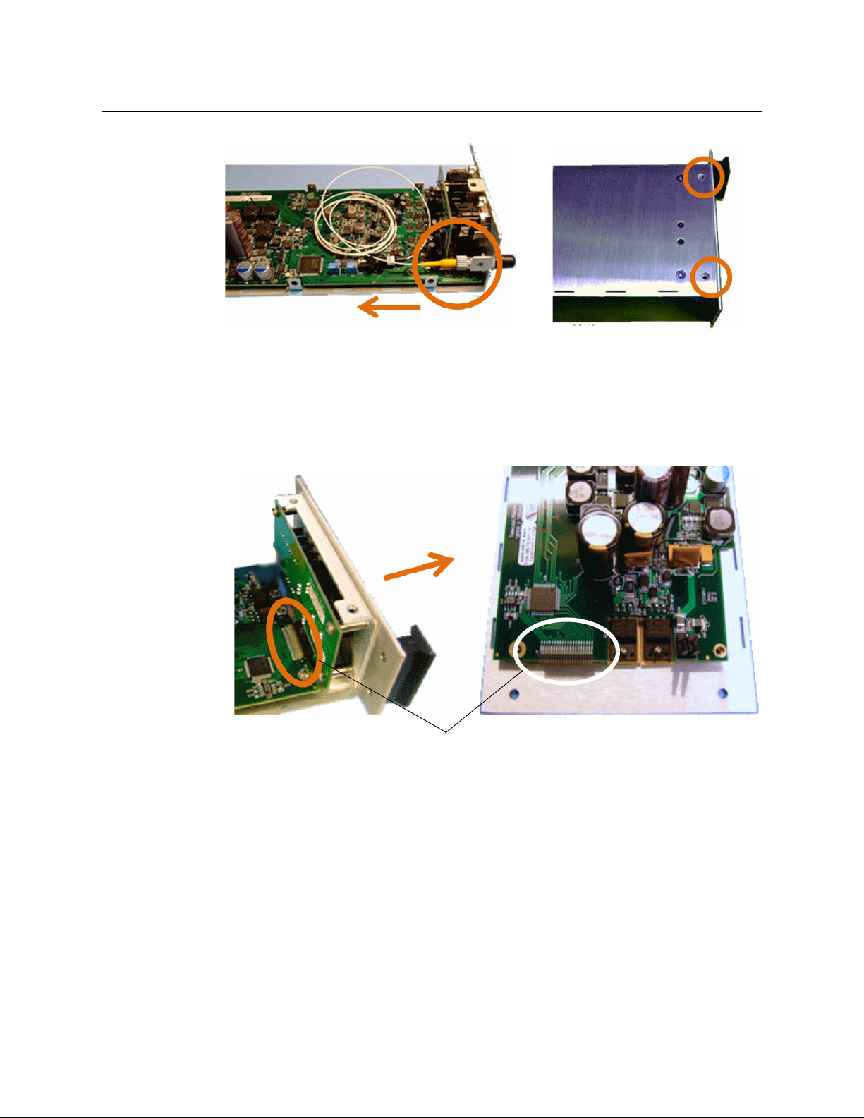
Fig. A-4: Removing cover screws
3 Carefully remove the orange power connector from the main circuit board.
Fig. A-5: Removing orange power connector
You can now set the unit cover aside for re-installation later.
4 Remove the Fiber Cable from the ST Barrel on the rear plate. Remove the connector by
pushing in and turning to the left. Protect the Fiber Cable connector from debris and
dust.
41
Page 46
CommLink TR6442i
Multi-pin connector
User Guide
Fig. A-6: Removing Fiber Cable (left) and the front panel (right)
5 Begin the process of removing the front panel by removing the two screws indicated.
Retain the screws for later re-use. Do not slide off the front panel.
6 Carefully slide the front panel straight out from the unit so as to not bend the
connector pins. This is a multi-pin connector and can be damaged if not handled
carefully.
Fig. A-7: Exposing the multi-pin connector
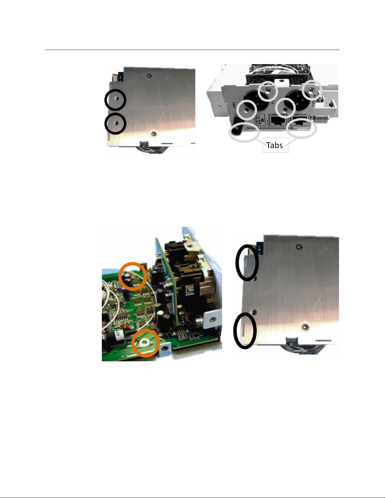
7 At the bottom rear of the unit, remove two screws that hold the back panel in place.
8 Remove the four screws from the back panel. These screws hold the connector board to
the panel. Do not attempt to remove the panel.
42
Page 47
Converting the TR6442i Viper II Rack Mount Unit
Note the two tabs that go into the bottom plate of the unit.
9 Once the screws are removed, pull the connector board up and away from the unit.
Make sure to not bend the ribbon connector. Set aside for re-installation.
10 On the main circuit board, loosen but DO NOT REMOVE the two screws indicated. This
will allow you to raise slightly the board and allows the rear panel to come clear of the
main unit.
Fig. A-8: Removing back panel screws
43
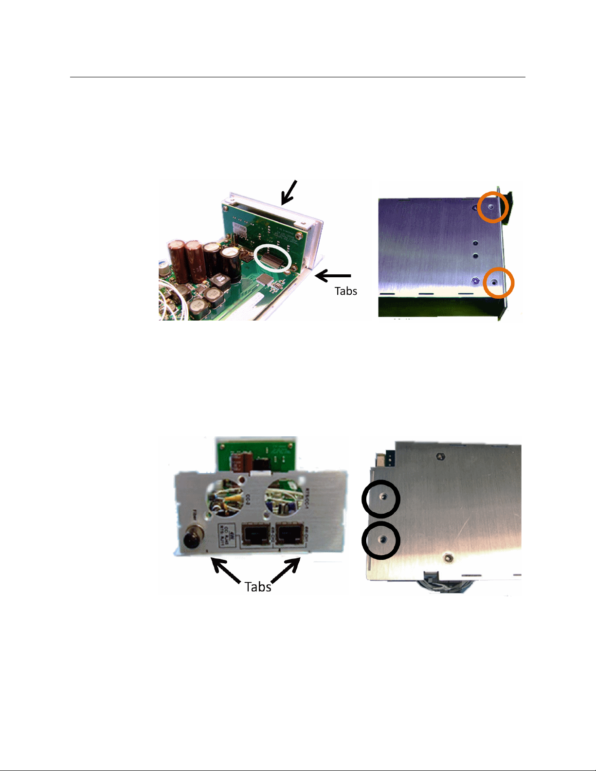
Fig. A-9: Removing the rear panel
Note the tabs/slots on the bottom of the unit. These tabs/slots are what you will be
clearing in order to remove the rear panel.
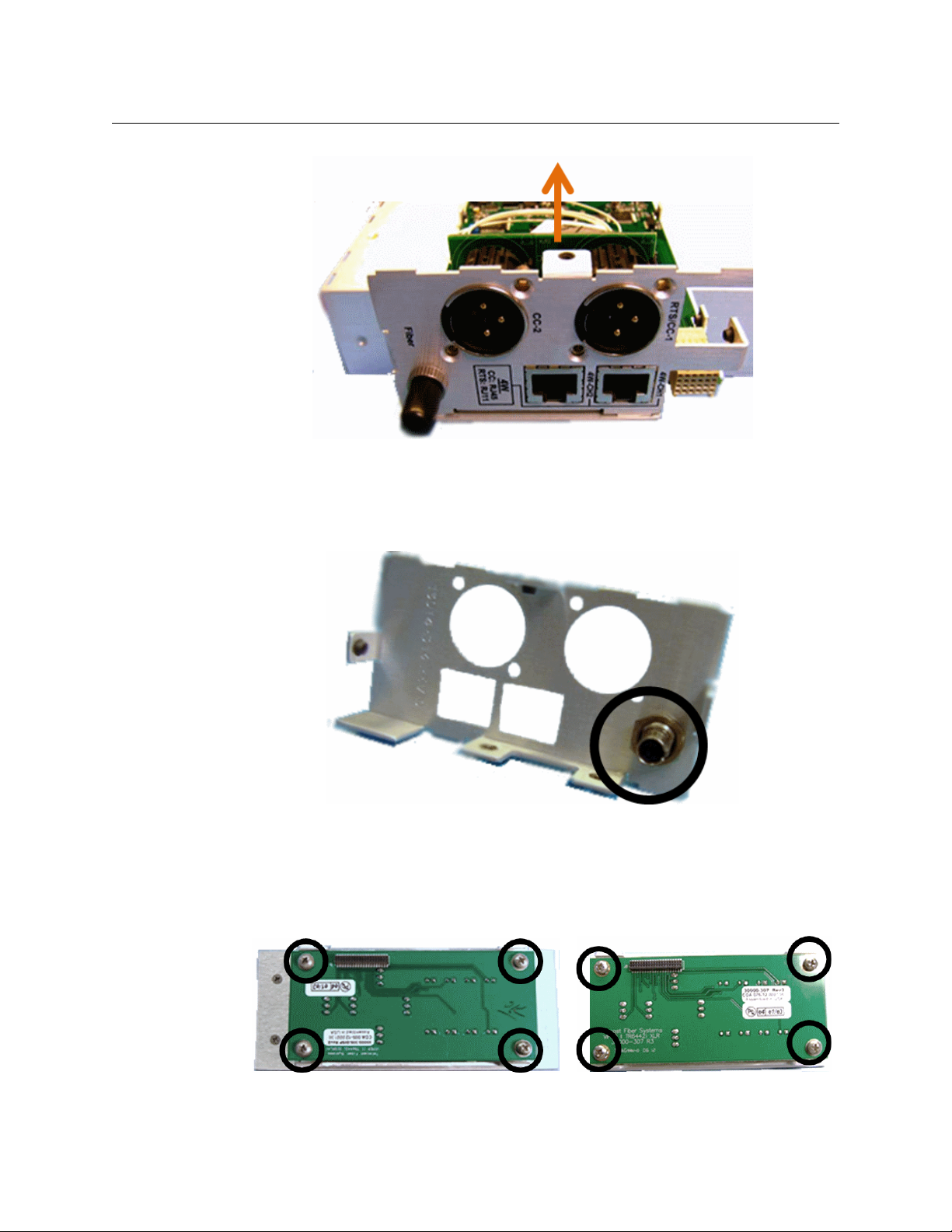
11 Lift the front panel slightly and pull out away from the unit. Make sure to clear the tabs.
The previous step of loosening the circuit board screws should give you the clearance
to remove the rear panel. If it does not feel free, completely remove the screws and
retain them for re-installation.
Page 48
CommLink TR6442i
User Guide
Fig. A-10: Removing the front panel
At this point, the connector panel should be removed from the unit (not shown).
12 Remove the ST Fiber Barrel from the Rack Mount version rear panel. The Barrel will be
used in the next step.
Fig. A-11: Remove the ST Fiber Barrel
13 Install the ST Fiber Barrel on the rear panel. The slotted side of the Barrel should be
installed so that it will face the exterior of the unit.
14 Remove the display circuit board from the Rack Mount version front panel. The board
and the four screws will be used in the next step.
Fig. A-12: The display circuit board screws
44
Page 49
Converting the TR6442i Viper II Rack Mount Unit
15 Install the display circuit board from the previous step to the Throw Down front panel
using the same four screws
16 Install the front plate assembly onto the base of the unit as shown. Carefully align the
connector of the ribbon connector. The pins should go straight in and align.
Once the front plate is properly seated and the tabs inserted into the bottom plate of
the unit, you are ready to secure the plate with the screw previously removed.
Fig. A-13: Securing the front panel
17 Secure the front plate with the two screws as shown in Figure A-13.
18 Install the rear plate on to the unit.
To get the tabs into place on the bottom plate of the unit, you must lift the main circuit
board as you did when removing the Rack Mount rear panel.
You may need to give the panel a small amount of pressure in order to the the 4 Wire
(RJ45 type) connectors in place over the EMI tabs.
Fig. A-14: Securing the back panel
19 Secure the back plate to the unit base by re-installing the two screws removed when
taking off the Rack Mount rear panel
20 Install the connector board onto the base. Be careful not to bend the connector pins.
45
Page 50

CommLink TR6442i
User Guide
Fig. A-15: Installing the connector board
Initially the board won't fit correctly - once the connectors are seated, pull the back
plate forward slightly and the board will fall into place.
21 Re-install the four self-tapping screws removed when the Rack Mount rear panel was
taken off of the main unit.
Fig. A-16: Reinstall the rear panel and tighten the main circuit board
22 Tighten (replace if you removed completely) the two screws holding the main circuit
board in place.
23 Re-install the Fiber Cable on to the ST Barrel. Make sure it locks into place.
24 Re-install the power connector. It is keyed to fit only one way.
46
Page 51

Converting the TR6442i Viper II Rack Mount Unit
Replace the cover on the unit making sure not to pinch the Fiber Cable and the Power
Cable between the cover and the main chassis.
25 Replace all nine screw removed in Steps 1 and 2. Three of the screws are shown here.
Fig. A-17: Re-install the power connector
47
Fig. A-18: Replace the screws and connect the power
26 Reconnect the CommLink unit to your system components and to power. Check that all
of the indicator LEDs and switches on the front panel function properly and that the
system performs as expected.
 Loading...