

Page 1

T-POV Bidirectional Robotic
Camera User Guide
M4017-9900-102
24 July 2014
Page 2

Notices
Copyright & Trademark Notice
Copyright © 2010–2014, Grass Valley. All rights reserved.
Belden, Belden Sending All The Right Signals, and the Belden logo are trademarks or
registered trademarks of Belden Inc. or its affiliated companies in the United States and
other jurisdictions. Grass Valley, T-POV Bidirectional Robotic Camera are trademarks or
registered trademarks of Grass Valley. Belden Inc., Grass Valley, and other parties may also
have trademark rights in other terms used herein.
Terms and Conditions
Please read the following terms and conditions carefully. By using T-POV documentation,
you agree to the following terms and conditions.
Grass Valley, a Belden Brand (“Grass Valley”) hereby grants permission and license to owners
of T-POV to use their product manuals for their own internal business use. Manuals for Grass
Valley products may not be reproduced or transmitted in any form or by any means,
electronic or mechanical, including photocopying and recording, for any purpose unless
specifically authorized in writing by Grass Valley.
A Grass Valley manual may have been revised to reflect changes made to the product
during its manufacturing life. Thus, different versions of a manual may exist for any given
product. Care should be taken to ensure that one obtains the proper manual version for a
specific product serial number.
Information in this document is subject to change without notice and does not represent a
commitment on the part of Grass Valley.
Warranty information is available in the Support section of the Grass Valley Web site
(www.miranda.com).
Title T-POV Bidirectional Robotic Camera User Guide
Part Number M4017-9900-102
Revision 24 July 2014
ii
Page 3

Table of Contents
1 About the T-POV Bidirectional Robotic Camera System . . . 1
T-POV Bidirectional Robotic Camera System concepts . . . . . . . . . . . . . . . . . . . . . . . . . . . . . . 2
Unpacking the T-POV Robotic Camera Link System . . . . . . . . . . . . . . . . . . . . . . . . . . . . . . . . . 3
Product Returns . . . . . . . . . . . . . . . . . . . . . . . . . . . . . . . . . . . . . . . . . . . . . . . . . . . . . . . . . . . . . . . 3
About this User Guide . . . . . . . . . . . . . . . . . . . . . . . . . . . . . . . . . . . . . . . . . . . . . . . . . . . . . . . . . 3
Product Ordering/Model Information . . . . . . . . . . . . . . . . . . . . . . . . . . . . . . . . . . . . . . . . . . . . . . 4
T-POV 301 Variations . . . . . . . . . . . . . . . . . . . . . . . . . . . . . . . . . . . . . . . . . . . . . . . . . . . . . . . . . . 4
T-POV 324 Variations. . . . . . . . . . . . . . . . . . . . . . . . . . . . . . . . . . . . . . . . . . . . . . . . . . . . . . . . . . 5
Safety and Fiber Optic Systems . . . . . . . . . . . . . . . . . . . . . . . . . . . . . . . . . . . . . . . . . . . . . . . . . . . . 6
Optical Fiber Safety. . . . . . . . . . . . . . . . . . . . . . . . . . . . . . . . . . . . . . . . . . . . . . . . . . . . . . . . . . . . 6
Power Fuses. . . . . . . . . . . . . . . . . . . . . . . . . . . . . . . . . . . . . . . . . . . . . . . . . . . . . . . . . . . . . . . . . . . 6
2 System Overview . . . . . . . . . . . . . . . . . . . . . . . . . . . . . . . . . . . . . . . 7
Fiber Cable Concepts . . . . . . . . . . . . . . . . . . . . . . . . . . . . . . . . . . . . . . . . . . . . . . . . . . . . . . . . . . . . . . 8
Fiber Optic Connector Types. . . . . . . . . . . . . . . . . . . . . . . . . . . . . . . . . . . . . . . . . . . . . . . . . . .9
Understanding which Fiber Connector is applicable . . . . . . . . . . . . . . . . . . . . . . . . . . . . 9
T-POV Bidirectional Robotic Camera System Components . . . . . . . . . . . . . . . . . . . . . . . . .10
T-POV Base Station Variables. . . . . . . . . . . . . . . . . . . . . . . . . . . . . . . . . . . . . . . . . . . . . . . . . .10
T-POV Base Station Physical Types . . . . . . . . . . . . . . . . . . . . . . . . . . . . . . . . . . . . . . . . . . . .11
T-POV Camera Unit Physical Types . . . . . . . . . . . . . . . . . . . . . . . . . . . . . . . . . . . . . . . . . . . .13
Signal paths in the T-POV Bidirectional Robotic Camera System . . . . . . . . . . . . . . . . . . . .14
Power options with the T-POV . . . . . . . . . . . . . . . . . . . . . . . . . . . . . . . . . . . . . . . . . . . . . . . . . . . .16
Power Mode and Fiber Connector Compatibility. . . . . . . . . . . . . . . . . . . . . . . . . . . . . . . . . . .17
Base Station Configurations . . . . . . . . . . . . . . . . . . . . . . . . . . . . . . . . . . . . . . . . . . . . . . . . . .17
Camera Unit Configurations . . . . . . . . . . . . . . . . . . . . . . . . . . . . . . . . . . . . . . . . . . . . . . . . . .17
3 T-POV 301 Components. . . . . . . . . . . . . . . . . . . . . . . . . . . . . . . . 19
About the T-POV 301 Components. . . . . . . . . . . . . . . . . . . . . . . . . . . . . . . . . . . . . . . . . . . . . . . .20
T-POV 301 Base Unit . . . . . . . . . . . . . . . . . . . . . . . . . . . . . . . . . . . . . . . . . . . . . . . . . . . . . . . . . . . . . .20
Base Unit Front Panel Detail . . . . . . . . . . . . . . . . . . . . . . . . . . . . . . . . . . . . . . . . . . . . . . . . . .20
Area A - Signal Indicator LEDs . . . . . . . . . . . . . . . . . . . . . . . . . . . . . . . . . . . . . . . . . . . . . . . . 21
Area B - Optical Power Indicator LED. . . . . . . . . . . . . . . . . . . . . . . . . . . . . . . . . . . . . . . . . . 21
Area C - Signal Strength & System Setup Display . . . . . . . . . . . . . . . . . . . . . . . . . . . . . . 22
Area D - Power/Status Indicators and Power Switch . . . . . . . . . . . . . . . . . . . . . . . . . . . 23
T-POV 301 Multiple Unit Detail. . . . . . . . . . . . . . . . . . . . . . . . . . . . . . . . . . . . . . . . . . . . . . . .24
AREA A . . . . . . . . . . . . . . . . . . . . . . . . . . . . . . . . . . . . . . . . . . . . . . . . . . . . . . . . . . . . . . . . . . . . . . 24
AREA B . . . . . . . . . . . . . . . . . . . . . . . . . . . . . . . . . . . . . . . . . . . . . . . . . . . . . . . . . . . . . . . . . . . . . . 24
AREA D . . . . . . . . . . . . . . . . . . . . . . . . . . . . . . . . . . . . . . . . . . . . . . . . . . . . . . . . . . . . . . . . . . . . . . 24
T-POV 301 Powered Unit Detail . . . . . . . . . . . . . . . . . . . . . . . . . . . . . . . . . . . . . . . . . . . . . . .25
Area D. . . . . . . . . . . . . . . . . . . . . . . . . . . . . . . . . . . . . . . . . . . . . . . . . . . . . . . . . . . . . . . . . . . . . . . 25
T-POV 301 Base Unit Rear Panel Detail. . . . . . . . . . . . . . . . . . . . . . . . . . . . . . . . . . . . . . . . .27
1
Page 4

Table of Contents
Area E - Power Section and Fiber Connector(s) . . . . . . . . . . . . . . . . . . . . . . . . . . . . . . . . 27
Area F - Data/GPI-Tally Connectors . . . . . . . . . . . . . . . . . . . . . . . . . . . . . . . . . . . . . . . . . . . 28
Area G - Video Connectors . . . . . . . . . . . . . . . . . . . . . . . . . . . . . . . . . . . . . . . . . . . . . . . . . . . 28
T-POV 301 Camera Unit . . . . . . . . . . . . . . . . . . . . . . . . . . . . . . . . . . . . . . . . . . . . . . . . . . . . . . . . . . .29
T-POV 301 Camera Unit Front Panel Detail - 12 Volt Model . . . . . . . . . . . . . . . . . . . . .30
Area A - Power Section (12 Volt Type). . . . . . . . . . . . . . . . . . . . . . . . . . . . . . . . . . . . . . . . . 30
Area B - Optical Power Strength and Diagnostic Display . . . . . . . . . . . . . . . . . . . . . . . 30
Area C - Signal Indicator LEDs . . . . . . . . . . . . . . . . . . . . . . . . . . . . . . . . . . . . . . . . . . . . . . . . 31
Area D - Fiber Connectors - "Dry" Unpowered Connectors . . . . . . . . . . . . . . . . . . . . . 31
T-POV 301 Camera Unit Front Panel Detail - Powered Model . . . . . . . . . . . . . . . . . . .32
Area E - 12-15 VDC Power Output . . . . . . . . . . . . . . . . . . . . . . . . . . . . . . . . . . . . . . . . . . . . 32
Area F - Fiber Connector . . . . . . . . . . . . . . . . . . . . . . . . . . . . . . . . . . . . . . . . . . . . . . . . . . . . . 32
T-POV 301 Camera Unit Rear Panel Detail . . . . . . . . . . . . . . . . . . . . . . . . . . . . . . . . . . . . .33
Area H - Video Connectors . . . . . . . . . . . . . . . . . . . . . . . . . . . . . . . . . . . . . . . . . . . . . . . . . . . 33
4 T-POV 324 Components. . . . . . . . . . . . . . . . . . . . . . . . . . . . . . . . 35
About the Camera Link System Components . . . . . . . . . . . . . . . . . . . . . . . . . . . . . . . . . . . . . .36
T-POV 324 Base Unit . . . . . . . . . . . . . . . . . . . . . . . . . . . . . . . . . . . . . . . . . . . . . . . . . . . . . . . . . . . . . .36
T-POV 324 Base Unit Front Panel Detail. . . . . . . . . . . . . . . . . . . . . . . . . . . . . . . . . . . . . . . .37
Area A - Signal Indicator LEDs . . . . . . . . . . . . . . . . . . . . . . . . . . . . . . . . . . . . . . . . . . . . . . . . 37
Area B - Signal Strength & System Setup Display . . . . . . . . . . . . . . . . . . . . . . . . . . . . . . 38
Area C - Power/Status Indicators and Power Switch . . . . . . . . . . . . . . . . . . . . . . . . . . . 39
T-POV 324 Multiple Unit Detail. . . . . . . . . . . . . . . . . . . . . . . . . . . . . . . . . . . . . . . . . . . . . . . .40
AREA A . . . . . . . . . . . . . . . . . . . . . . . . . . . . . . . . . . . . . . . . . . . . . . . . . . . . . . . . . . . . . . . . . . . . . . 40
AREA B . . . . . . . . . . . . . . . . . . . . . . . . . . . . . . . . . . . . . . . . . . . . . . . . . . . . . . . . . . . . . . . . . . . . . . 40
T-POV 324 Powered Unit Detail . . . . . . . . . . . . . . . . . . . . . . . . . . . . . . . . . . . . . . . . . . . . . . .41
Area A & B . . . . . . . . . . . . . . . . . . . . . . . . . . . . . . . . . . . . . . . . . . . . . . . . . . . . . . . . . . . . . . . . . . . 41
Area C . . . . . . . . . . . . . . . . . . . . . . . . . . . . . . . . . . . . . . . . . . . . . . . . . . . . . . . . . . . . . . . . . . . . . . . 41
T-POV 324 Base Unit Rear Panel Detail. . . . . . . . . . . . . . . . . . . . . . . . . . . . . . . . . . . . . . . . .43
Area D- Power Section and Fiber Connector(s) . . . . . . . . . . . . . . . . . . . . . . . . . . . . . . . . 43
Area E - Data/GPI-Tally Connectors & Ethernet . . . . . . . . . . . . . . . . . . . . . . . . . . . . . . . . 44
Area F - Audio Multi-Pin Connector . . . . . . . . . . . . . . . . . . . . . . . . . . . . . . . . . . . . . . . . . . . 45
Area G - Video Connectors . . . . . . . . . . . . . . . . . . . . . . . . . . . . . . . . . . . . . . . . . . . . . . . . . . . 45
T-POV 324 Camera Unit . . . . . . . . . . . . . . . . . . . . . . . . . . . . . . . . . . . . . . . . . . . . . . . . . . . . . . . . . . .46
T-POV 324 Camera Unit Front Panel Detail - 12 Volt Model . . . . . . . . . . . . . . . . . . . . .47
Area A - Power Section (12 Volt Type). . . . . . . . . . . . . . . . . . . . . . . . . . . . . . . . . . . . . . . . . 47
Area B - Optical Power Strength and Diagnostic Display . . . . . . . . . . . . . . . . . . . . . . . 47
Area C - Signal Indicator LEDs . . . . . . . . . . . . . . . . . . . . . . . . . . . . . . . . . . . . . . . . . . . . . . . . 48
Area D - Fiber Connectors - "Dry" Unpowered Connectors . . . . . . . . . . . . . . . . . . . . . 49
T-POV 324 Camera Unit Front Panel Detail - Powered Model . . . . . . . . . . . . . . . . . . .49
Area E - 12-15 VDC Power Output . . . . . . . . . . . . . . . . . . . . . . . . . . . . . . . . . . . . . . . . . . . . 49
Area F - Fiber Connector . . . . . . . . . . . . . . . . . . . . . . . . . . . . . . . . . . . . . . . . . . . . . . . . . . . . . 50
T-POV 324 Camera Unit Rear Panel Detail . . . . . . . . . . . . . . . . . . . . . . . . . . . . . . . . . . . . .50
Area G - Data/GPI-Tally Connectors . . . . . . . . . . . . . . . . . . . . . . . . . . . . . . . . . . . . . . . . . . . 51
Area H - Audio Multi-Pin Connector . . . . . . . . . . . . . . . . . . . . . . . . . . . . . . . . . . . . . . . . . . 51
Area I - Video Connectors . . . . . . . . . . . . . . . . . . . . . . . . . . . . . . . . . . . . . . . . . . . . . . . . . . . .51
5 Connecting the T-POV System . . . . . . . . . . . . . . . . . . . . . . . . . . 53
T-POV Usage Scenarios . . . . . . . . . . . . . . . . . . . . . . . . . . . . . . . . . . . . . . . . . . . . . . . . . . . . . . . . . . .54
2
Page 5

T-POV Bidirectional Robotic Camera
Tactical Fiber between the Base Station and Camera Unit . . . . . . . . . . . . . . . . . . . . . .54
Two Link Unit Installation with Tactical Fiber . . . . . . . . . . . . . . . . . . . . . . . . . . . . . . . . . .55
Hybrid Fiber between the Base Station and Camera Unit. . . . . . . . . . . . . . . . . . . . . . .56
Connections to the T-POV Base Station. . . . . . . . . . . . . . . . . . . . . . . . . . . . . . . . . . . . . . . . . . . .57
Connections to the T-POV Camera Unit. . . . . . . . . . . . . . . . . . . . . . . . . . . . . . . . . . . . . . . . . . . .59
6 Operation of the T-POV System. . . . . . . . . . . . . . . . . . . . . . . . . 61
Set Up Of The T-POV Robotic Camera Link System For Operation. . . . . . . . . . . . . . . . . . .62
Powering the System . . . . . . . . . . . . . . . . . . . . . . . . . . . . . . . . . . . . . . . . . . . . . . . . . . . . . . . . . . . . .63
Powering the T-POV Base Station . . . . . . . . . . . . . . . . . . . . . . . . . . . . . . . . . . . . . . . . . . . . .63
Powering the T-POV Camera Unit . . . . . . . . . . . . . . . . . . . . . . . . . . . . . . . . . . . . . . . . . . . . .63
A Brief Guide to Measurement of Fiber Optic Signal Strength . . . . . . . . . . . . . . . . . . . . . .64
The T-POV Base Station Digital Display. . . . . . . . . . . . . . . . . . . . . . . . . . . . . . . . . . . . . . . . . . . .65
Diagnostic Display Modes . . . . . . . . . . . . . . . . . . . . . . . . . . . . . . . . . . . . . . . . . . . . . . . . . . . .65
The T-POV Portable Unit Digital Display . . . . . . . . . . . . . . . . . . . . . . . . . . . . . . . . . . . . . . .68
Best Practices . . . . . . . . . . . . . . . . . . . . . . . . . . . . . . . . . . . . . . . . . . . . . . . . . . . . . . . . . . . . . . . . . . . .71
Shutting Down the System . . . . . . . . . . . . . . . . . . . . . . . . . . . . . . . . . . . . . . . . . . . . . . . . . . . . . . .72
Troubleshooting . . . . . . . . . . . . . . . . . . . . . . . . . . . . . . . . . . . . . . . . . . . . . . . . . . . . . . . . . . . . . . . . .72
User Guide
7 Specifications . . . . . . . . . . . . . . . . . . . . . . . . . . . . . . . . . . . . . . . . . 75
Appendix A: Connector Wiring and Connection . . . . . . . . . . . . 78
Wiring Diagrams . . . . . . . . . . . . . . . . . . . . . . . . . . . . . . . . . . . . . . . . . . . . . . . . . . . . . . . . . . . . . . . . .79
12 Volt DC Power Connection. . . . . . . . . . . . . . . . . . . . . . . . . . . . . . . . . . . . . . . . . . . . . . . . .79
15 Pin Serial Data Connection. . . . . . . . . . . . . . . . . . . . . . . . . . . . . . . . . . . . . . . . . . . . . . . . .79
26 Pin Serial Data Connection. . . . . . . . . . . . . . . . . . . . . . . . . . . . . . . . . . . . . . . . . . . . . . . . .80
25 Pin Audio Connection . . . . . . . . . . . . . . . . . . . . . . . . . . . . . . . . . . . . . . . . . . . . . . . . . . . . .80
Base Station 12VDC Terminal Block Wiring . . . . . . . . . . . . . . . . . . . . . . . . . . . . . . . . . . . .81
Serial Data Configuration . . . . . . . . . . . . . . . . . . . . . . . . . . . . . . . . . . . . . . . . . . . . . . . . . . . . . . . . .81
3
Page 6

Table of Contents
4
Page 7

About the T-POV Bidirectional Robotic
Camera System
This chapter provides a high-level overview of the T-POV Bidirectional Robotic Camera
system including how to order product and any related safety information.
T-POV Bidirectional Robotic Camera System concepts . . . . . . . . . . . . . . . . . . . . . . . . . . . . . . . . . . 2
Unpacking the T-POV Robotic Camera Link System . . . . . . . . . . . . . . . . . . . . . . . . . . . . . . . . . . . . 3
Product Ordering/Model Information . . . . . . . . . . . . . . . . . . . . . . . . . . . . . . . . . . . . . . . . . . . . . . . . . . 4
Safety and Fiber Optic Systems . . . . . . . . . . . . . . . . . . . . . . . . . . . . . . . . . . . . . . . . . . . . . . . . . . . . . . . . 6
1
Page 8
About the T-POV Bidirectional Robotic Camera System
T-POV Bidirectional Robotic Camera System concepts
T-POV Bidirectional Robotic Camera System concepts
The T-POV Bidirectional Robotic Camera is a camera video, audio, and data-multiplexing
system.It connects to a video camera and through a single fiber optic cable link to a Base
Station in a truck, studio, or other video production setup. All video, audio, and data
(usually carried on Triax or multi-core cable) is sent bi-directionally over a single lightweight
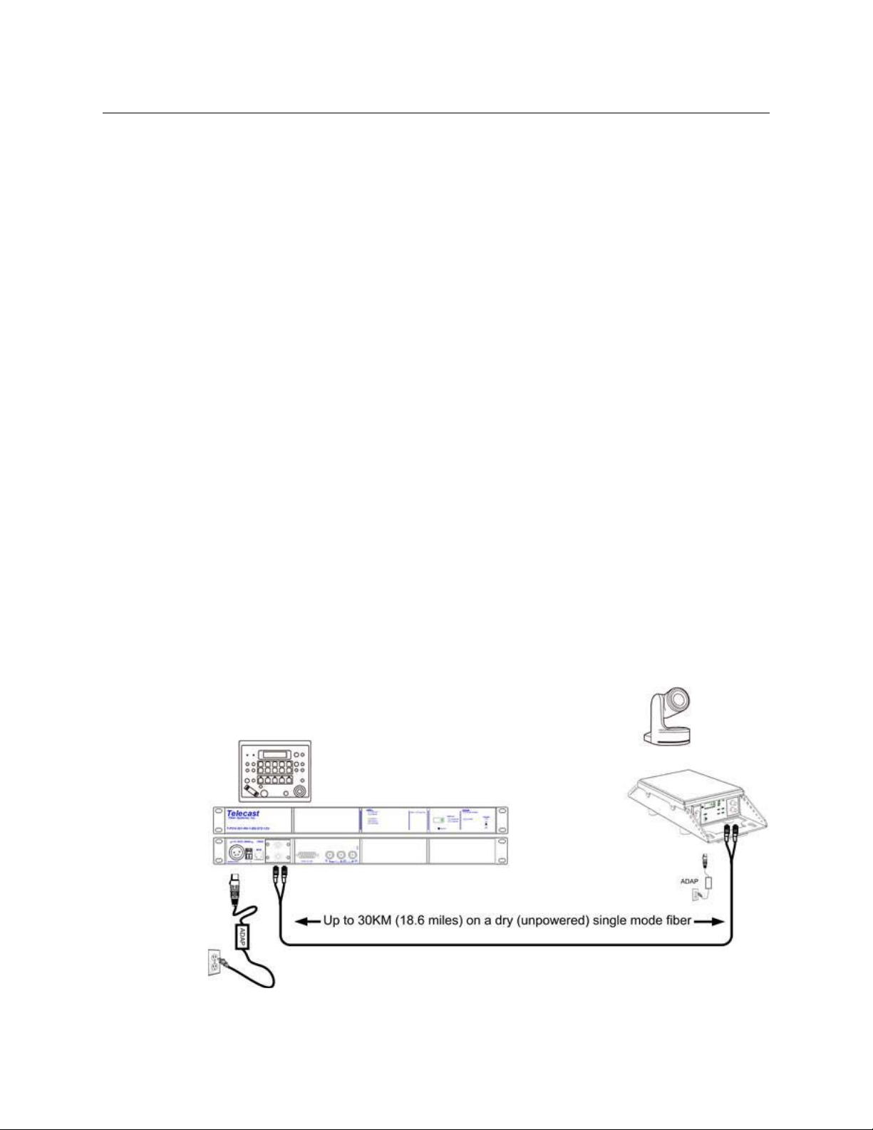
fiber cable over distances as long as 30 km (18.6 miles) or more. Hybrid cable systems can
extend 240 meters (787 feet).
A typical installation controls unmanned robotically-controlled cameras used in stadiums,
concert halls, high-end surveillance environments, traffic camera sites, and permanent
weather/beauty shot locations.
The T-POV comes in two variations each providing a specific complement of signals carried
on the fiber. Each variation can also be specified to provide power on the Fiber Optic Cable
("Wet") or without power carrying only the video, audio and data signals ("Dry").
The T-POV variations are the T-POV 301 and the T-POV 324.
The selection of the T-POV model depends on the particular video, audio, data, camera
control, tally/GPI, and power requirements of each application. Each of the T-POV variations
or models can be delivered in either a Rack Unit configuration or Portable "Mini-Mussel"
Shell configuration.
In summary, the differences between models depend on whether audio is carried on the
Fiber Optic cable and how much and what types of data, control and Tally/GPI information
is carried on the Fiber Optic cable. The two models are described in detail later in this user
guide and the two physical configurations are explained in T-POV Bidirectional Robotic
Camera System Components on page 10.
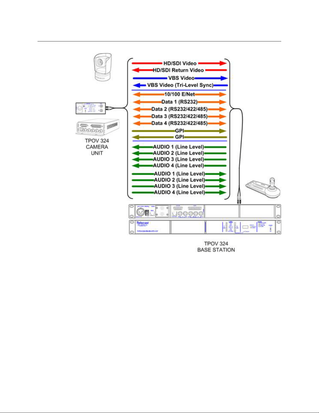
This illustration provides an example of a Base Station unit working with a single Camera
unit. This is one of many possible configurations. Detailed connection information is
provided in Connections to the T-POV Base Station on page 57 and Connections to the T-
POV Camera Unit on page 59.
Fig. 1-1: Example Usage Scenario
2
Page 9

In this usage example, a camera remote unit is attached to the T-POV base unit and controls
a remote camera connected to a T-POV Camera Unit.
The remote camera with controllable pan and tilt unit is connected to the T-POV Camera
Unit, which is connected to the Base Station over a Fiber Optic Cable. The Base Station is
connected to the camera manufacturer's Camera & Pan & Tilt Control unit over a data cable.
Configuration options are determined at the time of product order and the units are
delivered pre-configured.
Unpacking the T-POV Robotic Camera Link System
Please consult your packing slip and purchase order to ensure that you have received all of
the expected Fiber Systems components.
Inspect all components for scratches and other mechanical damage, and inspect the
electrical connectors for bent or damaged pins and latches. Report any missing or
damaged components to Grass Valley (see Product Returns on page 3).
You must use your own video and audio cables to make connections for Video, Audio,
GPI/Tally, Black Burst/Gen Lock, Base Station monitor, and other ancillary signals and data
or control equipment. Suggestions for these cables are discussed in Connector Wiring and
Connection on page 78).
T-POV
User Guide
Leave the protective caps on the optical connectors whenever the fiber is disconnected.
Product Returns
In the unlikely event of damage to your T-POV Robotic Camera Link System during shipping
or delivery,take note of any damage with the delivery or shipping service. If any
component does not work correctly out of the box, contact Grass Valley (see Contact Us on
page 77).
If the problem cannot be remedied through a service telephone call,you will receive an
RMA number (Return of Merchandise Authorization). Please note this RMA number inside
and outside of all shipping boxes and on all documentation provided with the items to be
returned.
About this User Guide
This T-POV Bidirectional Robotic Camera Link System can be delivered in a number of
configurations depending on the physical package selected. This User Guide is designed to
cover each of the various packages, so not every page in this Guide will apply to your
specific system.
3
Page 10
About the T-POV Bidirectional Robotic Camera System
Product Ordering/Model Information
Product Ordering/Model Information
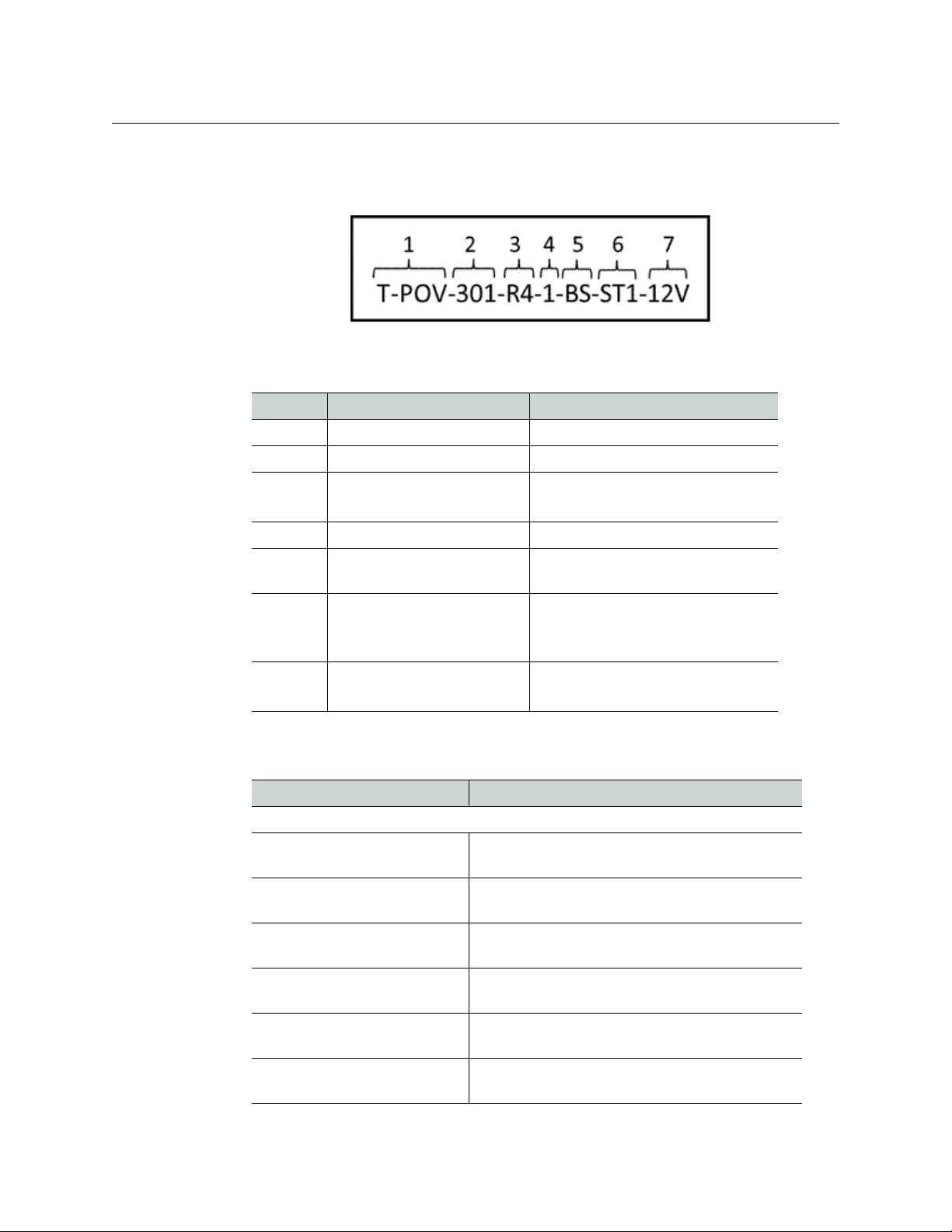
The T-POV part number consists of seven segments:
Fig. 1-2: T-POV part number format
Each segment represents a parameter describing the particular T-POV unit:
Segment Description Example
1Product DesignationT-POV
2 Model # 301 or 324
3 Physical Configuration R4 for Rack Mount
MML or MMH for Mini-Mussel Shell
4 Base Station or Camera Unit BS or CA
5 Unit Number (for Rack Unit
6 Connector Type ST1, ST2, ST4 for ST Fiber Connectors
7 Power Type 12V for external power
T-POV 301 Variations
Part No. Short Description
Base Stations
T-POV-301-R4-1-BS-ST1-12V 301 1 RU Single Base Station Rack Mount external
T-POV-301-R4-1-BS-ST2-12V 301 1 RU Single Base Station Rack Mount external
T-POV-301-R4-2-BS-ST2-12V 301 1 RU Dual Base Station Rack Mount external
T-POV-301-R4-2-BS-ST4-12V 301 1 RU Dual Base Station Rack Mount external
T-POV-301-R4-1-BS-304M-95V 301 1 RU Single Base Station Rack Mount internal
1 or 2
models only)
304M for SMPTE 304M Hybrid Fiber
Connector
95V for internally powered
power with 1 ST connector
power with 2 ST connectors
power with 2 ST connectors
power with 4 ST connectors
power with 304M connector
T-POV-301-MML-BS-ST1-12V 301 Single Base Station Mini-Mussel Shell external
power with 1 ST connector
4
Page 11

User Guide
Part No. Short Description
T-POV-301-MML-BS-ST2-12V 301 Single Base Station Mini-Mussel Shell external
power with 2 ST connectors
Camera Units
T-POV-301-R4-1-CA-ST1-12V 301 1 RU Single Base Station Rack Mount external
power with 1 ST connector
T-POV-301-R4-1-CA-ST2-12V 301 1 RU Single Base Station Rack Mount external
power with 2 ST connectors
T-POV-301-R4-2-CA-ST2-12V 301 1 RU Dual Base Station Rack Mount external
power with 2 ST connectors
T-POV-301-R4-2-CA-ST4-12V 301 1 RU Dual Base Station Rack Mount external
power with 4 ST connectors
T-POV-301-MML-CA-ST1-12V 301 Single Base Station Mini-Mussel Shell external
power with 1 ST connector
T-POV-301-MML-CA-ST2-12V 301 Single Base Station Mini-Mussel Shell external
power with 2 ST connectors
T-POV-301-MMH-CA-304M-95V 301 Single Base Station Mini-Mussel Shell internal
power with 304M connector
T-POV
T-POV 324 Variations
Part No. Short Description
Base Stations
T-POV-324-R4-1-BS-ST1-12V 324 1 RU Single Base Station Rack Mount external
T-POV-324-R4-1-BS-ST2-12V 324 1 RU Single Base Station Rack Mount external
T-POV-324-R4-2-BS-ST2-12V 324 1 RU Dual Base Station Rack Mount external
T-POV-324-R4-2-BS-ST4-12V 324 1 RU Dual Base Station Rack Mount external
T-POV-324-R4-1-BS-304M-95V 324 1 RU Single Base Station Rack Mount internal
T-POV-324-MML-BS-ST1-12V 324 Single Base Station Mini-Mussel Shell external
T-POV-324-MML-BS-ST2-12V 324 Single Base Station Mini-Mussel Shell external
Camera Units
T-POV-324-R4-1-CA-ST1-12V 324 1 RU Single Base Station Rack Mount external
power with 1 ST connector
power with 2 ST connectors
power with 2 ST connectors
power with 4 ST connectors
power with 304M connector
power with 1 ST connector
power with 2 ST connectors
power with 1 ST connector
T-POV-324-R4-1-CA-ST2-12V 324 1 RU Single Base Station Rack Mount external
power with 2 ST connectors
5
Page 12

About the T-POV Bidirectional Robotic Camera System
Safety and Fiber Optic Systems
Part No. Short Description
T-POV-324-R4-2-CA-ST2-12V 324 1 RU Dual Base Station Rack Mount external
T-POV-324-R4-2-CA-ST4-12V 324 1 RU Dual Base Station Rack Mount external
T-POV-324-MML-CA-ST1-12V 324 Single Base Station Mini-Mussel Shell external
T-POV-324-MML-CA-ST2-12V 324 Single Base Station Mini-Mussel Shell external
T-POV-324-MMH-CA-304M-95V 324 Single Base Station Mini-Mussel Shell internal
Safety and Fiber Optic Systems
Optical Fiber Safety
power with 2 ST connectors
power with 4 ST connectors
power with 1 ST connector
power with 2 ST connectors
power with 304M connector
Power Fuses
To prevent damaging your eyes, never look directly into the end of the optic fiber while
either end of the system is operating.
Always use cable connector caps when the Fiber Optic cables are not connected. This
protects the connector from damage and the unlikely event of exposure to an operating
optical link. Keeping the caps in place when the connectors are not in use will prevent dirt
and dust from entering the connector and degrading the performance of the optical link
The T-POV Powered Base Stations are equipped with Dual Cartridge fuses located next to
the AC Power receptacle at the left rear of the unit.
NEVER operate a T-POV Powered Base Station without properly installed and rated fuses.
Severe electrical and heat damage to the equipment could result, as well as personal injury
or death.
6
Page 13

System Overview
This chapter lists the main components and options for the T-POV Bidirectional Robotic
Camera system including an overview of Fiber Cable technology.
Fiber Cable Concepts . . . . . . . . . . . . . . . . . . . . . . . . . . . . . . . . . . . . . . . . . . . . . . . . . . . . . . . . . . . . . . . . . . 8
T-POV Bidirectional Robotic Camera System Components . . . . . . . . . . . . . . . . . . . . . . . . . . . . . 10
Signal paths in the T-POV Bidirectional Robotic Camera System . . . . . . . . . . . . . . . . . . . . . . . 14
Power options with the T-POV . . . . . . . . . . . . . . . . . . . . . . . . . . . . . . . . . . . . . . . . . . . . . . . . . . . . . . . . 16
Power Mode and Fiber Connector Compatibility . . . . . . . . . . . . . . . . . . . . . . . . . . . . . . . . . . . . . . 17
7
Page 14
System Overview
Fiber Cable Concepts
Fiber Cable Concepts
Fiber Optics and Fiber Optic Cable are the core technologies at the heart of the T-POV
Robotic Camera Link System. The T-POV System features the ability to multiplex and demultiplex a variety of video, audio and data signals so that they can be carried over a thin
strand of Fiber Optic cable for long distances. The theory and operation of Fiber Optics is
beyond the scope of this document, but you need to be aware of the different types of
Fiber Optic Cable and Fiber Optic Cable Connectors.
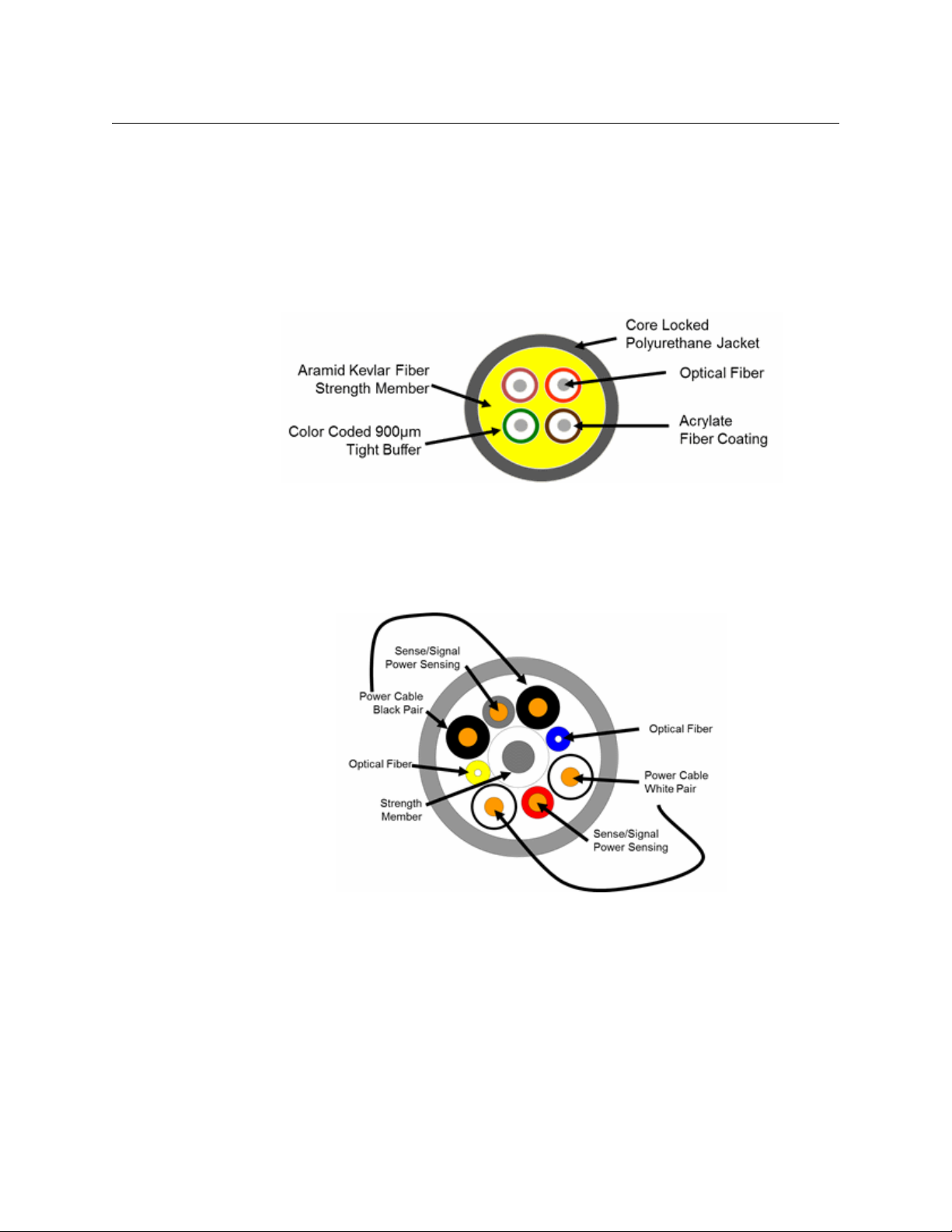
Tactical Fiber cable is heavy duty; Kevlar protected and capable of carrying T-POV signals
extended distances. The cable can generally withstand a variety of environmental hazards
(such as being crushed or run-over). When used on Portable Fiber Reels, Tactical Fiber can
be used in the field in lengths of up to 2000 feet.
Fig. 2-1: Tactical Fiber Optic Cable Cross-section (Illustrative only)
Fig. 2-2: Hybrid Fiber Optic Cable Cross-section (Illustrative only)
Hybrid Fiber Cable has the same Fiber Optic characteristics with the addition of copper
cables, which allows the transmission of power through the cable. This increases weight
and reduces operating distance.
Hybrid Fiber Cable also includes a pair of Sense/Signal wires that allow systems to
determine if there is an open or shorted cable. Hybrid Fiber Cable is also larger in diameter
than Tactical Fiber Cable.
8
Page 15
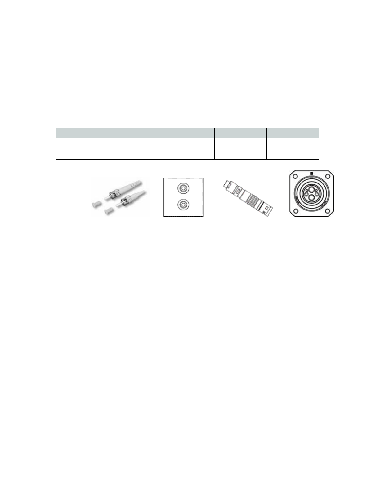
Fiber Optic Connector Types
ST Cable Connectors ST Panel Connectors SMPTE 304M
Cable connector
SMPTE 304M
Panel Connector
The T-POV Robotic Camera Link System is delivered with one of two types of Fiber
Connectors.
• For 12 Volt systems using Tactical Fiber Cable, the system is delivered with ST
Connectors.
• For AC Powered Base Unit systems, the T-POV is delivered with an SMPTE 304M type
hybrid powered fiber connector.
Connector Type Tactical Fiber Use Hybrid Fiber Use Camera Unit Use Base Station Use
Fiber Connectors Yes Not Typically Yes Yes
SMPTE 304M No Yes Yes Yes
T-POV
User Guide
Fig. 2-3: Fiber Optic Connectors
The specific application of Fiber Optic connectors in T-POV systems is covered in
Understanding which Fiber Connector is applicable on page 9
Understanding which Fiber Connector is applicable
The selection of Fiber Connector type in the T-POV system depends on the following:
• Is the system an externally powered 12 Volt system or is the system internally powered
at the Base Station by 120VAC? Note that all AC powered units can be configured for
120VAC or 240VAC operation.
• What is the number of Link units installed in the base station?
The choice of Fiber Connectors applies to both models of the T-POV Robotic Camera
Link System. For a detailed list of Fiber Connector and Power Mode compatibility, see
the following sections:
• For a general discussion of Fiber Connectors, see Fiber Cable Concepts on page 8.
• For a detailed list of Fiber Connector and Power Mode compatibility, see Power
Mode and Fiber Connector Compatibility on page 17.
Powered T-POV Units are delivered with the SMPTE 304M Hybrid Connector. Twelve Volt
models use some variation of ST connectors depending on configuration and whether the
system has one or two link units installed.
9
Page 16

System Overview
T-POV Bidirectional Robotic Camera System Components
T-POV Bidirectional Robotic Camera System Components
The T-POV system is comprised of a Base Station and one or two Camera Units. Any system
must consist of Base Station and Camera Units that are of the same model type (ex.: a T-POV
301 Base Station will only work with a T-POV 301 Camera Unit). The same holds true for
each of the T-POV 324 model: you cannot mix and match a 301 with a 324.
To understand the specific capabilities of the two models, please see the following sections
on Signal Paths in the T-POV and the individual chapters on each model type:
• T-POV 301 Components on page 19
• T-POV 324 Components on page 35
T-POV Base Station Variables
The T-POV Base station variations are summarized in the following table. For additional
information, see Product Ordering/Model Information on page 4 or consult with Grass
Valley (see Contact Us on page 77) or your Fiber Systems dealer.
Note that "12V" and "95V" refer to T-POV model types. Both externally powered and AC
powered versions of the T-POV provide 12 Volts of power. The powered version additionally
provides 95 Watts of 12 Volt power at the Camera Unit for use by the camera and
accessories. The power is delivered through a Hybrid Fiber Optic Cable as described in Fiber
Cable Concepts on page 8.
Number
Housing
Single - Mini-Mussel 1 ST1, ST2, SMPTE
Rack Mount 1 or 2 ST1, ST2, ST4, 12V "dry"
Rack Mount 1 SMPTE 304M
of Units
Fiber Connector Power Option
12V "dry" or 95V "wet" (power type
304M (powered)
(powered)
dictates Fiber Connector choice)
95V "wet"
10
Page 17
T-POV Base Station Physical Types
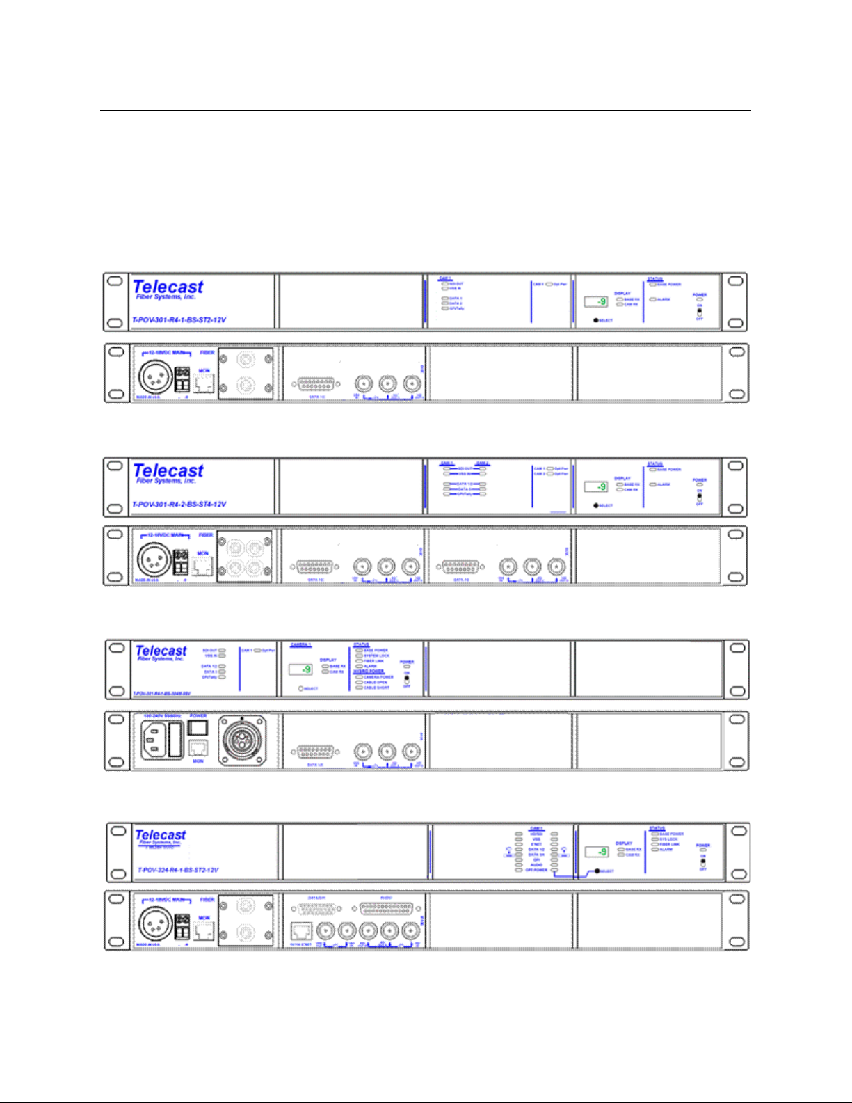
This section illustrates a selection of the more commonly specified T-POV Base Station
physical types. For detailed illustrations of each device, see T-POV 301 Components on
page 19 and T-POV 324 Components on page 35.
See Product Ordering/Model Information on page 4 for a complete list of available T-POV
models.
Fig. 2-4: Externally powered T-POV 301 single rack unit with 2 ST Fiber Connectors
T-POV
User Guide
Fig. 2-5: Externally powered T-POV 301 dual rack unit with 4 ST Fiber Connectors
Fig. 2-6: Internally (AC) powered T-POV 301 rack unit with 1 SMPTE 304M Fiber Connector
Fig. 2-7: Externally powered T-POV 324 rack unit with 2 ST Fiber Connectors
11
Page 18
System Overview
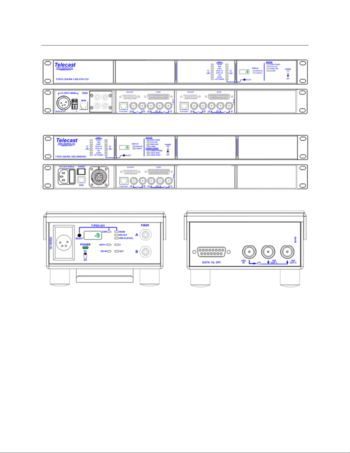
T-POV Base Station Physical Types
Fig. 2-8: Externally powered T-POV 324 dual rack unit with 4 ST Fiber Connectors
Fig. 2-9: Internally (AC) powered T-POV 324 rack unit with 1 SMPTE 304M Fiber Connector
Fig. 2-10: Externally powered T-POV 301 Mini-Mussel unit with 2 ST Fiber Connectors
The T-POV 324 version is similar with additional connectors and LED indicators.
12
Page 19
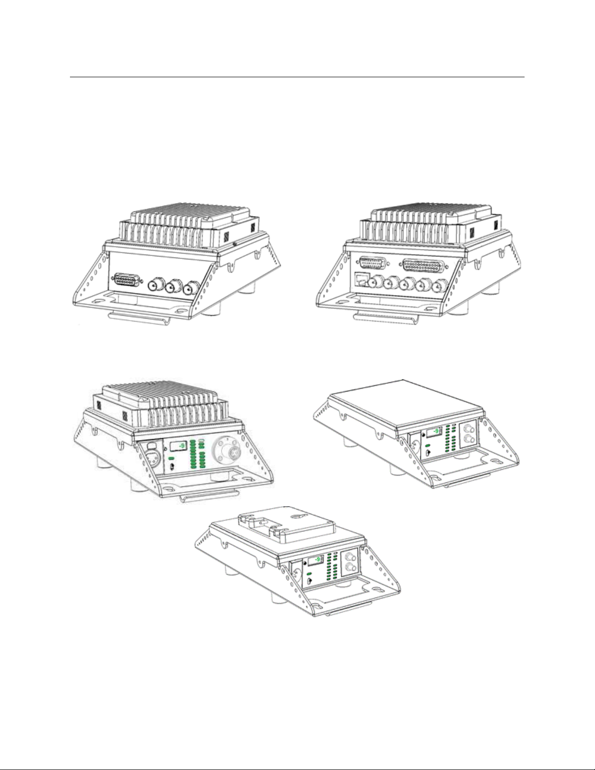
T-POV Camera Unit Physical Types
T-POV 301 Camera Unit -Rear Panel T-POV 324 Camera Unit -Rear Panel
T-POV 324 Camera Unit Front
Panel - Internal Power
(From Hybrid Fiber Optic
Cable)
T-POV 324 Camera Unit
Front Panel - External
Power
T-POV 324 Camera Unit Front
Panel - External Power with
Battery Mount Option
(Anton-Bauer Battery Mount
Shown)
This section illustrates the various Mini-Mussel Shell T-POV Camera Unit physical types.
Rack Mount Camera Units are similar to the Rack Mount Base Station physical
configurations. System labels are not shown in these illustrations for purposes of clarity.
See Product Ordering/Model Information on page 4 for a complete list of available T-POV
models. Note the T-POV 324 is used for illustration of the front panel. The T-POV 301 front
panel differs only in the number of LED indicators.
T-POV
User Guide
Fig. 2-11: Camera Unit Rear Panels
Fig. 2-12: Camera Unit Front Panels
13
Page 20
System Overview
Signal paths in the T-POV Bidirectional Robotic Camera System
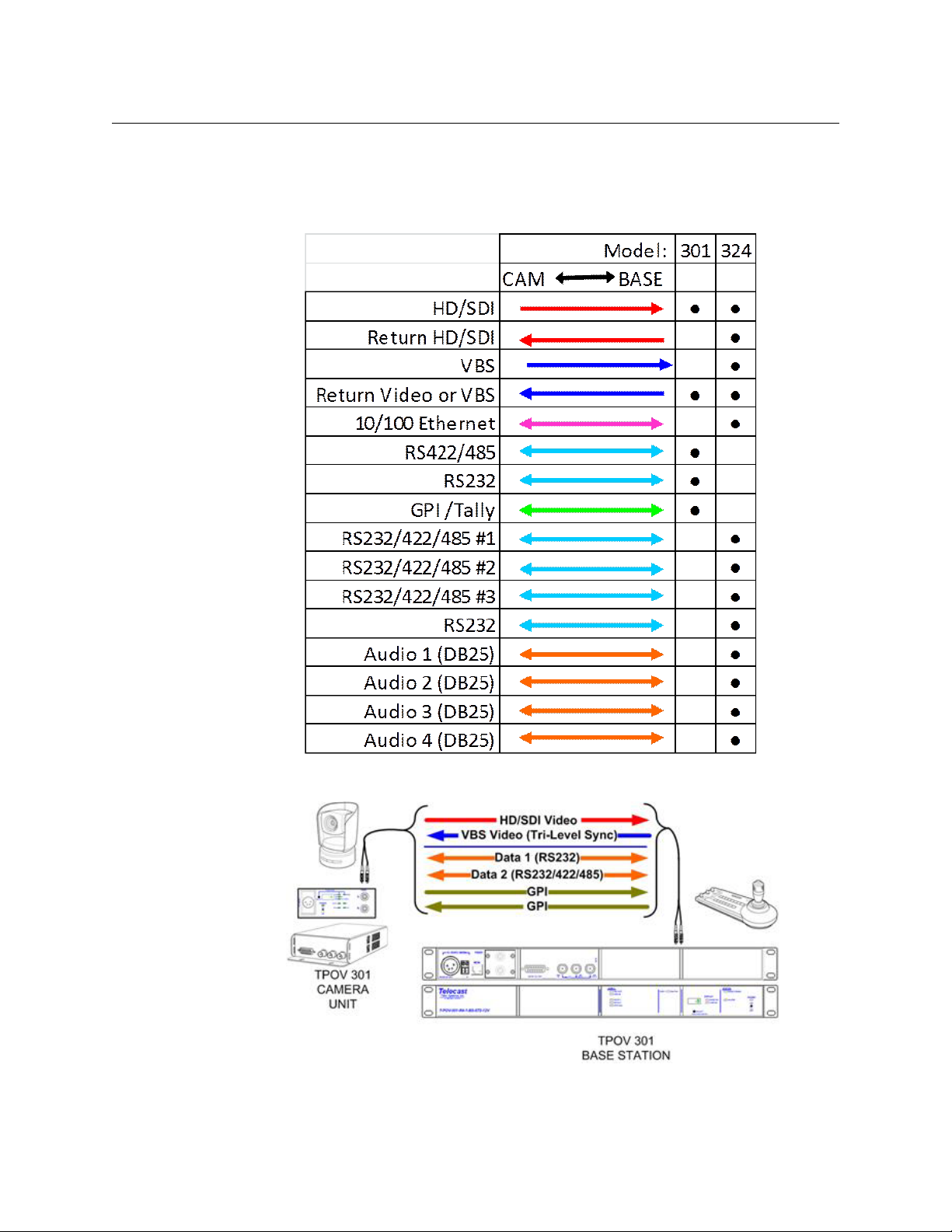
Signal paths in the T-POV Bidirectional Robotic Camera System
All of the Rack Mount and Mini-Mussel Shell variations of a particular model carry the same
signal set whether internally or externally powered.
14
Fig. 2-13: T-POV 301 Camera Link Signal Paths
Fig. 2-14: T-POV 324 Camera Link Signal Paths
Page 21
T-POV
User Guide
Fig. 2-15: T-POV 324 Camera Link Signal Paths
15
Page 22
System Overview
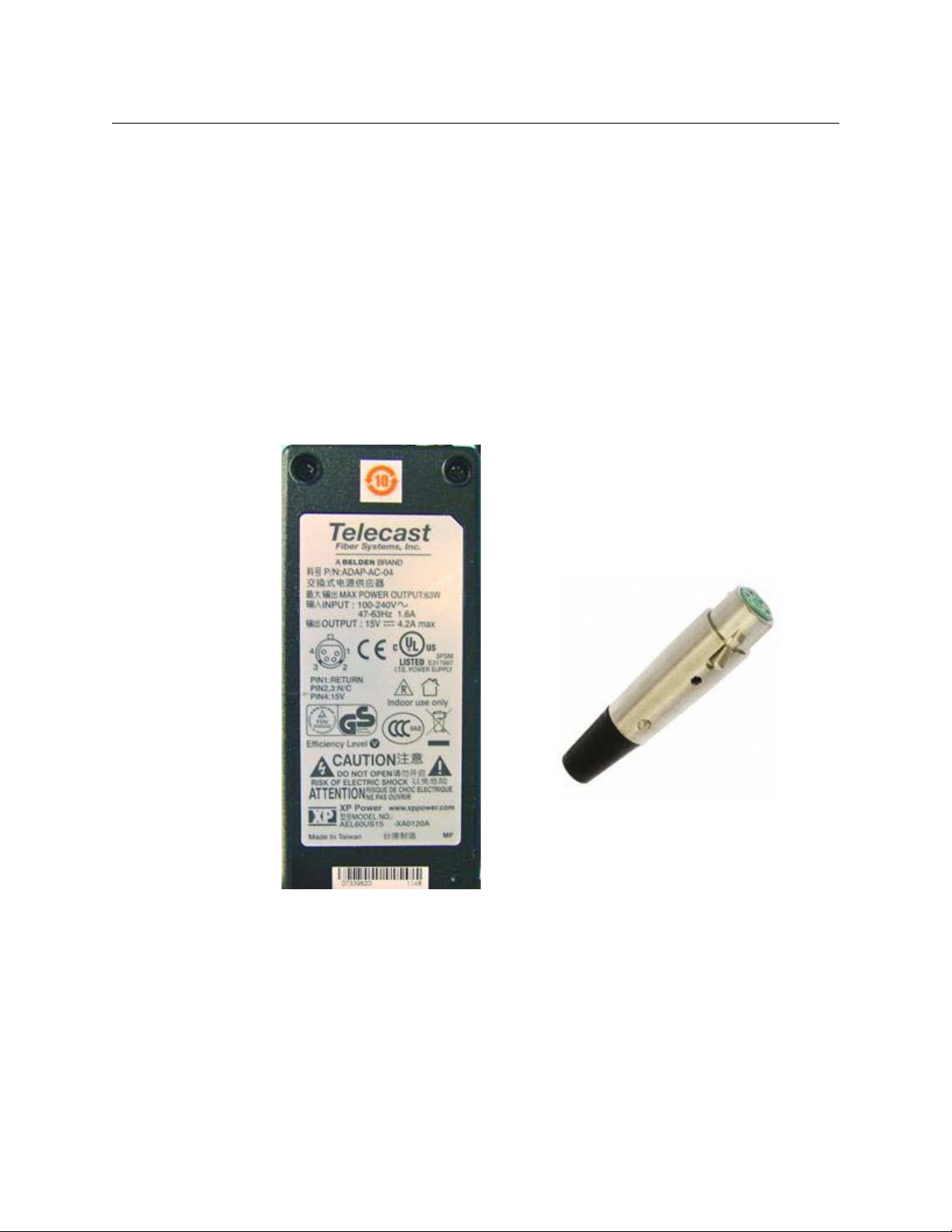
Part Number
ADAP-AC-04
Supplied with 4PIN
XLR/A4F connector
Power options with the T-POV
Power options with the T-POV
The T-POV Robotic Camera Link System has two methods of power for both the Base
Station and the Camera Unit. The Base Station can be powered externally by a 12 Volt
power supply (ADAP-AC-04 is recommended), which will work across a 100-240VAC range.
The Base Station can also be powered with an internal AC power supply. This power supply
provides power to a single Link unit in the Base Station and also provides power down the
Hybrid Fiber Link cable to the Camera Unit.
The externally powered Base Station requires only one power supply regardless of the
number of Camera Link units installed.
The externally powered Camera Unit can be powered by a 12 Volt Power supply, such as the
ADAP-AC-04. The Camera Unit can also be equipped with a 12 Volt battery mount to
provide operation independent of the AC mains or as an on-board power backup. Mounts
for Anton Bauer or V-Mount type batteries are available.
Fig. 2-16: ADAP-AC-04 Power Supply?
16
Page 23

Power Mode and Fiber Connector Compatibility
Base Station Configurations
Chart applies to both models of T-POV
T-POV
User Guide
Power Mode
External 12 Volt 1 2 ST
External 12 Volt 1 1 ST Requires WDM (Wave Division
External 12 Volt 2 4 ST
Internal AC 1 SMPTE 304M
Camera Unit Configurations
Chart applies to both models of T-POV.
Power Mode Fiber Connector Power Mode
External 12 Volt 1 ST (with WDM) Internal AC SMPTE 304M
External 12 Volt 2 ST
The following chapters cover each T-POV model type individually. Please confirm your TPOV model type and proceed to the appropriate chapter.
• T-POV 301 - T-POV 301 Components on page 19
• T-POV 324 - T-POV 324 Components on page 35
Number of
Link Units
Fiber
Connector
Notes
Multiplexing) Unit in order to have
bi-directional signals on signal
fiber
Fiber
Connector
17
Page 24

System Overview
Camera Unit Configurations
18
Page 25

T-POV 301 Components
This chapter describes the components in the 301 model of the T-POV Bidirectional Robotic
Camera system.
About the T-POV 301 Components . . . . . . . . . . . . . . . . . . . . . . . . . . . . . . . . . . . . . . . . . . . . . . . . . . . . 20
T-POV 301 Base Unit . . . . . . . . . . . . . . . . . . . . . . . . . . . . . . . . . . . . . . . . . . . . . . . . . . . . . . . . . . . . . . . . . . 20
T-POV 301 Camera Unit . . . . . . . . . . . . . . . . . . . . . . . . . . . . . . . . . . . . . . . . . . . . . . . . . . . . . . . . . . . . . . 29
19
Page 26
T-POV 301 Components
About the T-POV 301 Components
About the T-POV 301 Components
The T-POV 301 Robotic Camera Link Base Station and Camera Unit come in both portable
and rack mount configurations. In this chapter, the system components are described using
a single unit rack mounted base station with external 12 Volt power and a standard MiniMussel Shell version of the Camera Unit also with external 12 Volt power.
The variations for the internally powered Base Station and the powered version of the
Camera Unit are described following the 12 Volt versions. Characteristics that are unique to
the two link 12 Volt Base Stations are also described. The two link rack mounted Camera
Units operate similarly to the two link unit Base Stations.
• T-POV 301 Base Unit on page 20
• T-POV 301 Camera Unit on page 29
T-POV 301 Base Unit
• Base Unit Front Panel Detail on page 20
• T-POV 301 Multiple Unit Detail on page 24
• T-POV 301 Powered Unit Detail on page 25
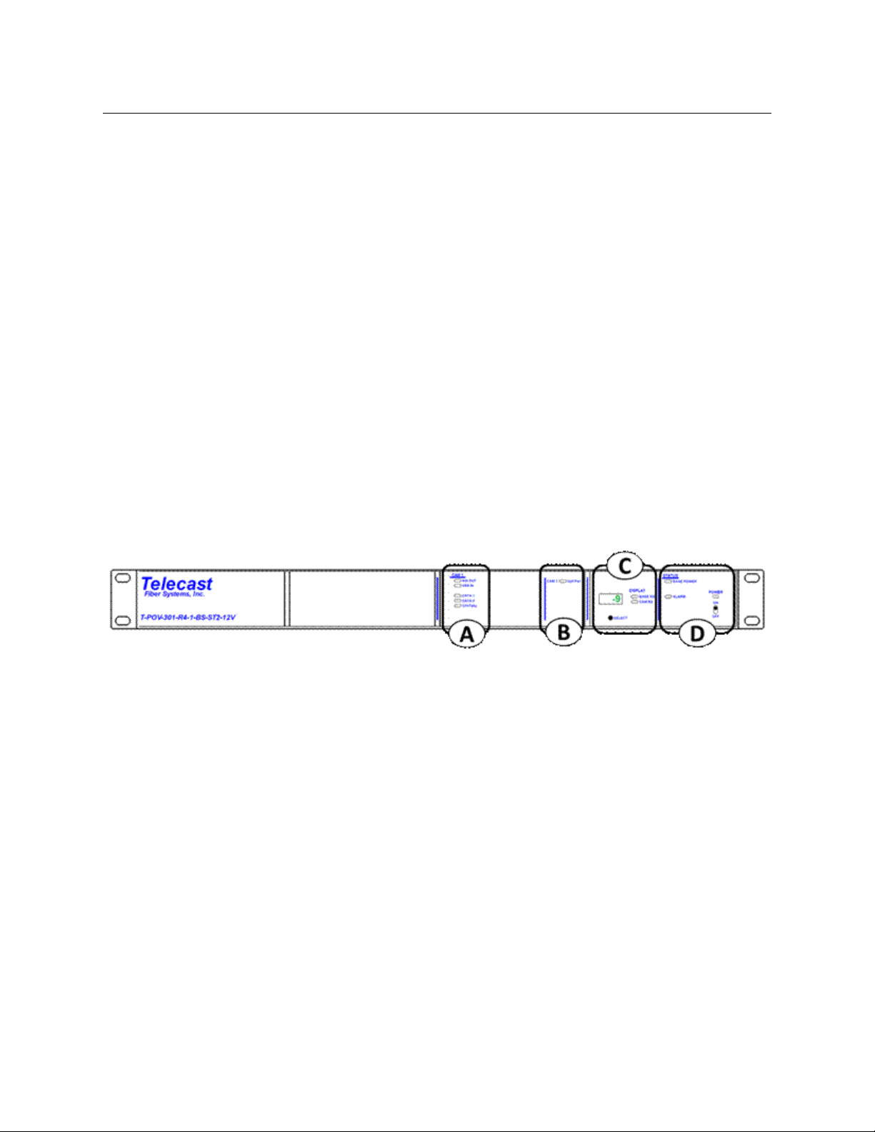
Base Unit Front Panel Detail
The T-POV Base Station Front Panel has four features:
• A: Signal Indicator LEDs (see Area A - Signal Indicator LEDs on page 21)
• B: Optical Power Indicator LED (see Area B - Optical Power Indicator LED on page 21)
• C: Signal Strength & System Setup Display (see Area C - Signal Strength & System
Setup Display on page 22)
• D: Power/Status Indicators and Power Switch (see Area D - Power/Status Indicators
and Power Switch on page 23)
Fig. 3-1: T-POV 301 Base Station Front Panel
20
Page 27
T-POV
User Guide
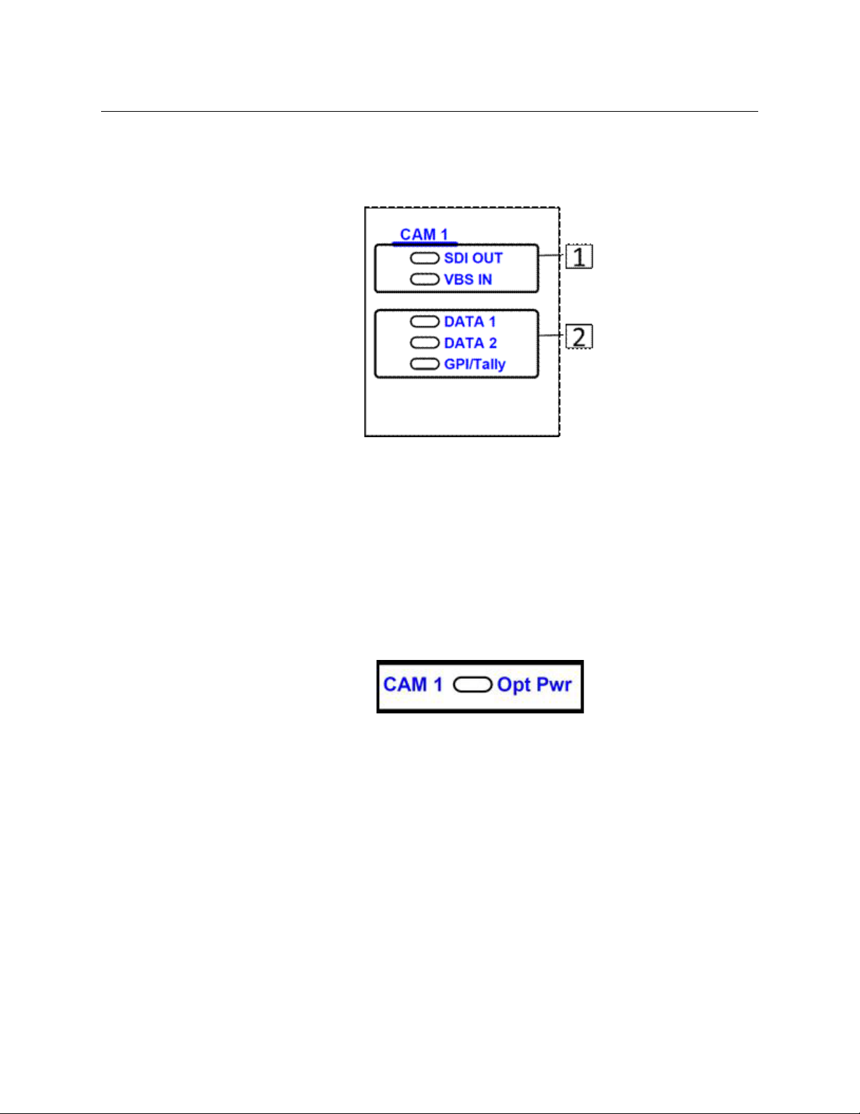
Area A - Signal Indicator LEDs
The five LED indicators in this area monitor the various signals being sent to and from the
Camera Unit. LEDs will glow Green when a signal is present.
Fig. 3-2: Signal Indicator LEDs
• 1: SDI OUT - monitors camera video signal returning from the Camera Unit to the Base
Station
• VBS IN - monitors the black burst/sync signal or return video signal being sent to
the Camera Unit
• 2: DATA 1 - monitors data activity on Data Path 1
• DATA 2 - monitors data activity on Data Path 2
• GPI/Tally - monitors GPI/Tally signal activity
Area B - Optical Power Indicator LED
Fig. 3-3: Optical Power Indicator LED
Opt Pwr - When the LED is lit Green, this indicates that the Optical link between the base
station and the camera unit is locked and functioning.
The LED will turn Red if there is a problem with the Optical Link at the Base Station. The LED
will turn Amber if there is a problem at the Camera Unit.
21
Page 28

T-POV 301 Components
Base Unit Front Panel Detail
Area C - Signal Strength & System Setup Display
• 1: SELECT - selects between three modes of operation. When power is turned on, the
unit defaults to BASE RX display mode.
Note: Pushing and holding the SELECT button will enter diagnostics mode, while a
quick push will return to the Base Station display. Only Base Station diagnostics appear
on the Base Station; you must be at the camera unit for camera unit diagnostics. The
ALARM STATUS LED (see Area D - Power/Status Indicators and Power Switch
will light Amber if there is a problem with the Camera Unit.
Fig. 3-4: Signal Strength & System Setup Display
• BASE RX - indicates display mode is Optical Link signal strength received at Base
Station from Camera Unit
• CAM RX - indicates display mode is Optical Link signal strength received at Camera
from Base Station
• DIAGNOSTIC - displays various alphanumeric readouts
on page 23)
• 2: DISPLAY - indicates which unit Optical Link level is being displayed. Neither LED is lit
when the unit is in diagnostics mode.
• 3: Digital Display - indicates Optical Link signal strength in dBm units. Also diagnostic
information when Base Station is in diagnostics modes.
For additional information on both measuring optical link strength and T-POV
diagnostics, see A Brief Guide to Measurement of Fiber Optic Signal Strength on
page 64 and The T-POV Base Station Digital Display on page 65.
22
Page 29

Area D - Power/Status Indicators and Power Switch
Fig. 3-5: Power/Status Indicators and Power Switch
• 1: POWER - power indicator lights Green when the power switch is toggled on.
Indicates that power supply levels are good.
• 2: STATUS:
• BASE POWER - monitors power levels on all circuit boards within the Base Station.
If any internal power levels are incorrect the LED will light Red.
• ALARM - lights Red if there is a temperature, power, hardware or firmware fault in
the base unit system. The indicator will light Amber if there is a fault at the Camera
Unit.
T-POV
User Guide
23
Page 30

T-POV 301 Components
T-POV 301 Multiple Unit Detail
T-POV 301 Multiple Unit Detail
The T-POV 301 Multiple Unit Base Station differs from the single unit model in that there are
additional LED indicator columns for Camera 2 in Area A and additional Optical Power
indicators in Area B. Component operation differences are noted below.
Fig. 3-6: T-POV 301 Multiple Unit Base Station
AREA A
The indicator AREA A in the two unit Base Station operates identically to that of a single unit
model (see Area A - Signal Indicator LEDs on page 21). The indicator LEDs monitor functions
independently of each other.
AREA B
Fig. 3-7: T-POV 301 Multiple Unit Base Station -- Area B
The Opt Pwr indicators illuminate as the Select button is toggled through the two Camera
Units. The indicators will light Red if there is no optical connection. A blinking Opt Pwr LED
indicates that a camera link optical power level is being displayed on the Digital Display in
Area C.
AREA D
Fig. 3-8: T-POV 301 Multiple Unit Base Station -- Area D
SELECT button chooses between three modes of operation.
24
When the Base Station is powered on, Base Station optical power is displayed. The first push
of the SELECT button will select CAM 1; the second push will select CAM 2.
Pushingand holding the SELECT button will enter the diagnostics mode for the device
currently being displayed.
Page 31

T-POV 301 Powered Unit Detail
The T-POV 301 Powered Unit base station is delivered with one Optical Link unit. The
physical configuration differs from the 12 Volt model in that the Optical Link unit with its
power supply occupies one-half of the rack mount chassis and the Camera 1 unit is placed
on the left side of the chassis. The term Hybrid Power refers to the integration of 95 Watts of
12 Volt power into the fiber optic cable.
Fig. 3-9: T-POV 301 Powered Unit base station
The T-POV Powered Base Station Front Panel has five features:
• A: Signal Indicator LEDs
• B: Optical Power Indicator LED
• C: Signal Strength & System Setup Display
• D: Power/Status Indicators and Power Switch
T-POV
User Guide
Area D
Areas A through C function identically to that of the 12 Volt version of the T-POV Base
Station. The differences are in Area D - the Power/Status Indicators and Power Switch.
Fig. 3-10: T-POV 301 Powered Unit base station -- Area D
• 1: POWER - lights Red when the AC power main switch on the rear of the unit is turned
on and the front power switch is off. The indicator lights Green when the front panel
power switch is toggled on.
With a powered system (power supplied by the Base Station) this switch will control
power to the Camera Unit
For the hybrid system to be powered on, the AC Mains switch on the rear of Base
Station must be in the on position.
•2: HYBRID POWER INDICATORS
• CAMERA POWER - indicates that high voltage is applied to power the camera.
25
Page 32

T-POV 301 Components
T-POV 301 Powered Unit Detail
• CABLE OPEN - indicates that the high voltage cable is open or there is no high
• CABLE SHORT - indicates that the high voltage cable connected is shorted.
• 3: STATUS INDICATORS
• BASE POWER - indicates the status of all power levels in the Base Station
• SYSTEM LOCK - indicates that the Base Station is communicating with the Camera
• FIBER LINK - indicates the optical power status of the Base Station and camera
• ALARM - Indicator will light Red if there is a temperature, power, hardware or
• Green when high voltage is being supplied to the camera.
Off when there is no high voltage applied to the camera
voltage cable connected.
• Green when the cable is properly connected from the Base Station to the
camera.
• Red when there no cable connected to the camera or the cable is connected
but open.
High voltage will not be applied to the camera until the open condition is
corrected.
• Green when all power levels are normal.
• Red when any power level is not normal.
Unit.
• Green when communicating with Camera Unit
• Red when it is not communicating with the Camera Unit
• Green when both the Base Station and camera optical power are within a
normal range.
• Red when both the Base Station and camera optical power are not within a
normal range
• Amber when either the Base Station or camera optical power are not within a
normal range
firmware fault in the base unit system. The indicator will light Amber if there is a
fault at the Camera Unit.
• Red if there is a Base Station error. Refer to the Base Station DIAG for details on
the error.
• Amber if there is a camera error. Refer to CAM DIAG for details for the error.
26
Page 33
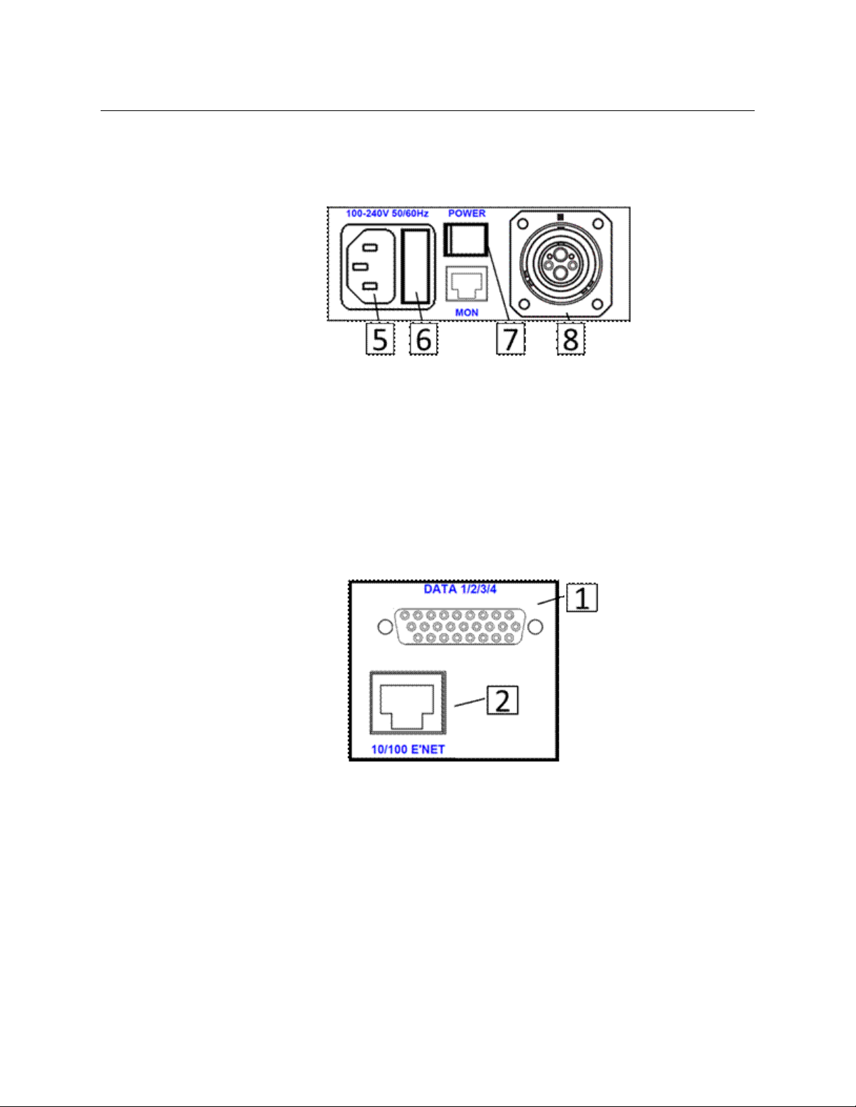
T-POV 301 Base Unit Rear Panel Detail
The Base Unit rear panel Area diagram is repeated for reference. In multi-unit Base Stations
camera one is on the left next to the power and fiber connector section. Camera two is to
the right of camera one and camera three is to the right of camera two (if so equipped).
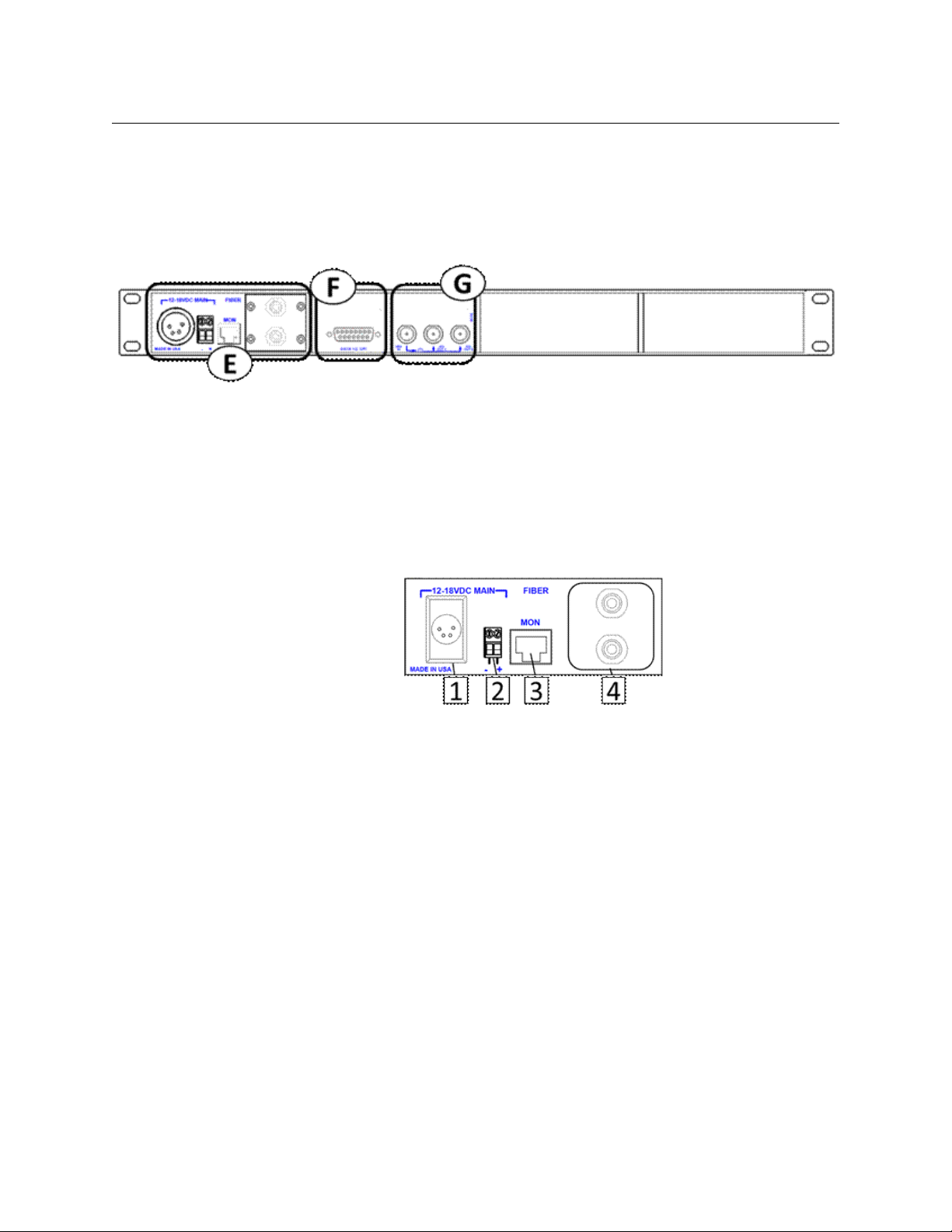
Fig. 3-11: T-POV 301 Base Station Rear/Connector Panel
The T-POV Base Station Connector Panel has four features:
• E: Power Section and Fiber Connector(s)
• F: Data/GPI-Tally Connector
• G: Video Connectors
T-POV
User Guide
Area E - Power Section and Fiber Connector(s)
Fig. 3-12: T-POV 301 Base Station Rear/Connector Panel -- Area E
12 Volt models have a single power supply/fiber connection area regardless of the number
of Optical Link units configured
12 Volt Power Models
• 1: 12V DC External Power Supply input connector (XLR 4 Pin) -
For use with an external power supply such as the ADAP-AC-04
See Connector Wiring and Connection on page 78 for connection details
• 2: 12V DC Input - terminal block
For use in rack mounted installations as an option to an external "brick" type power
supply. See Connector Wiring and Connection on page 78 for connection details
• 3: For Future Use
• 4: ST Connectors
95 Watt Powered Models
• 5: AC Power Receptacle
100-240V 50/60 Hz
27
Page 34
T-POV 301 Components
T-POV 301 Base Unit Rear Panel Detail
• 6: 4 AMP Dual Fuse Assembly
The fuses supplied are standard 4 Ampere fuses - 5 x 20mm. Both fuses are in operation
at all times - both the AC Line Hot and the AC Line Neutral are fused.
• 7: AC Mains Power Switch - this must be turned on in order for the front panel power
switch to work
• 8: SMPTE 304M Fiber Connector (Powered)
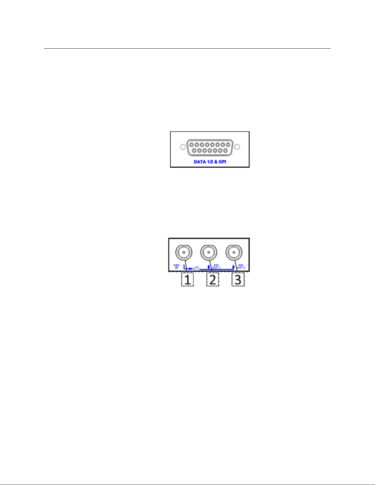
Area F - Data/GPI-Tally Connectors
DATA 1/2 & GPI - Provides up to two bi-directional data feeds and a GPI feed. Available are
RS232, RS422 and RS485 data formats.
For configuration and wiring information on all data & GPI connections please see
Connector Wiring and Connection on page 78.
Fig. 3-13: T-POV 301 Base Station Rear/Connector Panel -- Area F
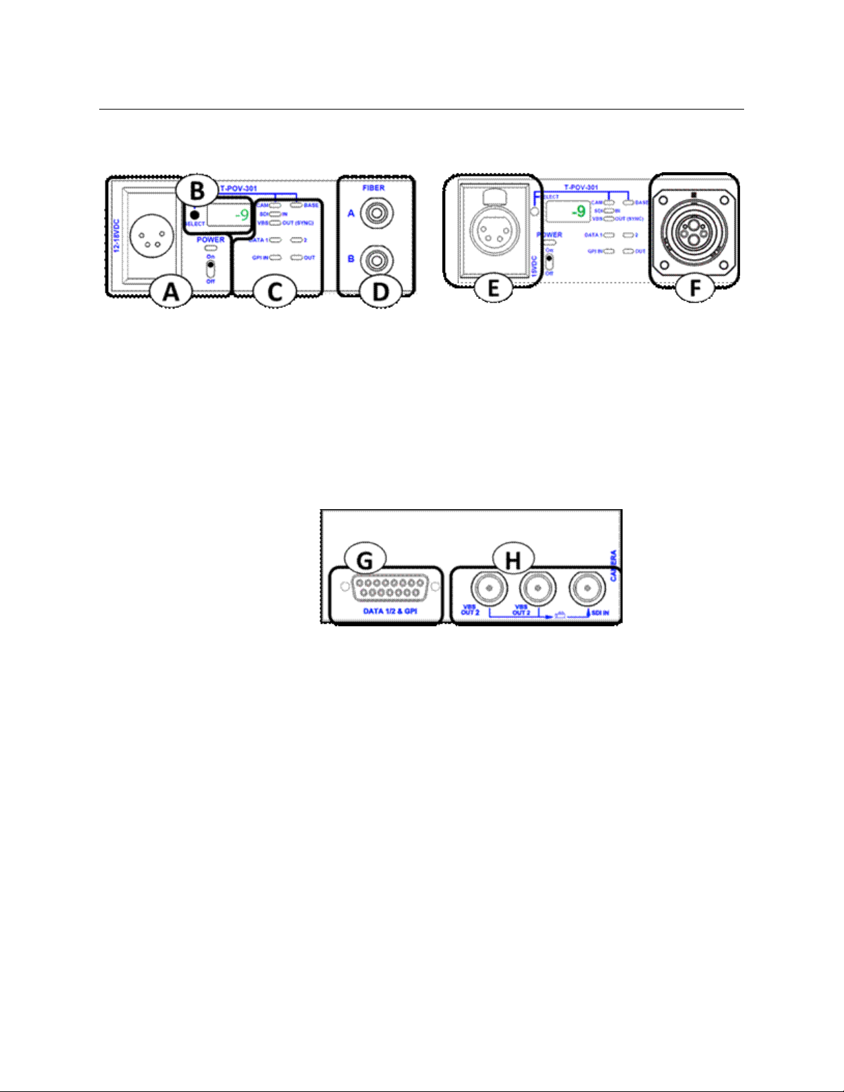
Area G - Video Connectors
Fig. 3-14: T-POV 301 Base Station Rear/Connector Panel -- Area G
• 1: VBS IN - Video black burst/sync or return video to Camera unit
• 2 & 3: SDI OUT 1 & 2 - SDI Video signal coming from Camera Unit
28
Page 35
T-POV 301 Camera Unit
The T-POV 301 Camera Unit Front Panel has six features:
• A: Power Section (12 Volt Type)
• B: Optical Power Strength and Diagnostic Display
• C: Signal Indicator LEDs
• D: ST Fiber Connectors
• E: 12-15 VDC Power Output (AC Powered Version only)
• F: SMPTE 304M Fiber Connector ("Wet" with 95 Watts of 12 Volt power available)
T-POV
User Guide
Fig. 3-15: T-POV 301 Camera Unit Front Panel
Fig. 3-16: T-POV 301 Camera Unit Front Panel
The T-POV 301 Camera Unit Rear Panel has two features:
• G: Data/GPI-Tally Connector
• H: Video Connectors
The T-POV Camera Unit rear panel is identical in the 12 Volt and Powered versions.
29
Page 36
T-POV 301 Components
T-POV 301 Camera Unit Front Panel Detail - 12 Volt Model
T-POV 301 Camera Unit Front Panel Detail - 12 Volt Model
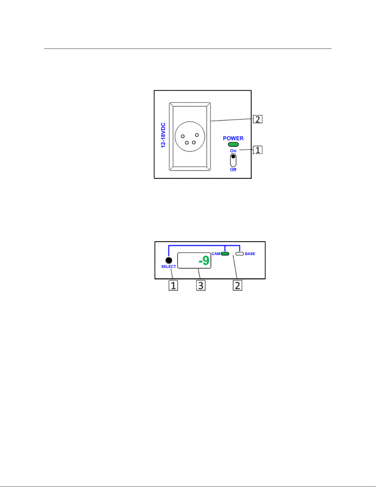
Area A - Power Section (12 Volt Type)
Fig. 3-17: T-POV 301 Camera Unit Front Panel -- Area A
• 1: POWER - lights Green when the power switch is toggled on.
• 2: 12-18 VDC Power Connection - 4-Pin XLR Female chassis connector for use with an
external power supply such as the ADAP-AC-04 or equivalent
Area B - Optical Power Strength and Diagnostic Display
Fig. 3-18: T-POV 301 Camera Unit Front Panel -- Area B
• 1: DISPLAY SELECT - push button chooses between three modes of operation
When power is turned on, the Camera Unit optical power is first displayed. The first
push of the select button will select the Base Station
Pushingand holding the SELECT button will enter diagnostics, otherwise a quick push
will return to the camera unit display.
• 2: CAM/BASE Indicators - LEDs indicate which unit Optical Power is displayed. Neither
LED is on when the display is in diagnostics mode.
• 3: DISPLAY - optical power is displayed in dBm units and diagnostic information is
alphanumeric. Only Camera Unit diagnostics can be viewed at the Camera Unit (Base
Station diagnostics are not available at the Camera Unit)
For more information on measuring optical power and using system diagnostics please see
A Brief Guide to Measurement of Fiber Optic Signal Strength on page 64 and The T-POV
Base Station Digital Display on page 65.
30
Page 37

T-POV
User Guide
Area C - Signal Indicator LEDs
The eight LED indicators in this area monitor the various signals being sent to or from the
Camera Unit. LEDs will light Green when a signal is present.
Note: LEDs labeled "IN" indicate signals coming into the camera unit. LEDs labeled "OUT"
indicate signals coming out of the Base Station. If there is neither "IN" or "OUT" associated
with an LED then activity in either the Camera Unit and Base Station is indicated
Fig. 3-19: T-POV 301 Camera Unit Front Panel -- Area C
• 1: SDI IN - monitors camera video signal to the Base Station
VBS OUT (SYNC) - monitors the black burst/sync signal or return video signal being
sent to the camera
• 2: DATA - monitors the two data channels available with the T-POV.
• 3: GPI - monitors GPI/Tally pulse to and from Camera Unit
Area D - Fiber Connectors - "Dry" Unpowered Connectors
Fig. 3-20: T-POV 301 Camera Unit Front Panel -- Area AD
FIBER CONNECTORS - Shown are 2 ST connectors. Can be any available unpowered Fiber
Connector depending on user requirements and number of camera units installed.
For additional information please see Fiber Cable Concepts on page 8 on Fiber Connectors
and Product Ordering/Model Information on page 4 regarding ordering information.
31
Page 38

T-POV 301 Components
T-POV 301 Camera Unit Front Panel Detail - Powered Model
T-POV 301 Camera Unit Front Panel Detail - Powered Model
The T-POV 301 Powered Camera Unit receives power from the Base Station over the Hybrid
Fiber Cable connection. The 12 Volt and Powered version of the T-POV 301 operate
identically with two exceptions. The powered version provides a 12-15 Volt output for
camera and accessory power and the Fiber Connection must of necessity be a Hybrid Fiber
Cable connection.
Area E - 12-15 VDC Power Output
Fig. 3-21: T-POV 301 Camera Unit Front Panel -- Area E
12-15 VDC Power Output - provides up to 95 Watts of 12 Volt power for the camera or
accessories. Please ensure that the total power drain on this source is no more than 95
Watts.
For connector wiring information, see Connector Wiring and Connection on page 78
Area F - Fiber Connector
Fig. 3-22: T-POV 301 Camera Unit Front Panel -- Area F
Fiber Connector - SMPTE 304M Hybrid power fiber connection carries signals to and from
the Base Station and 95 Watts of12 Volt power from the base station.
32
Page 39
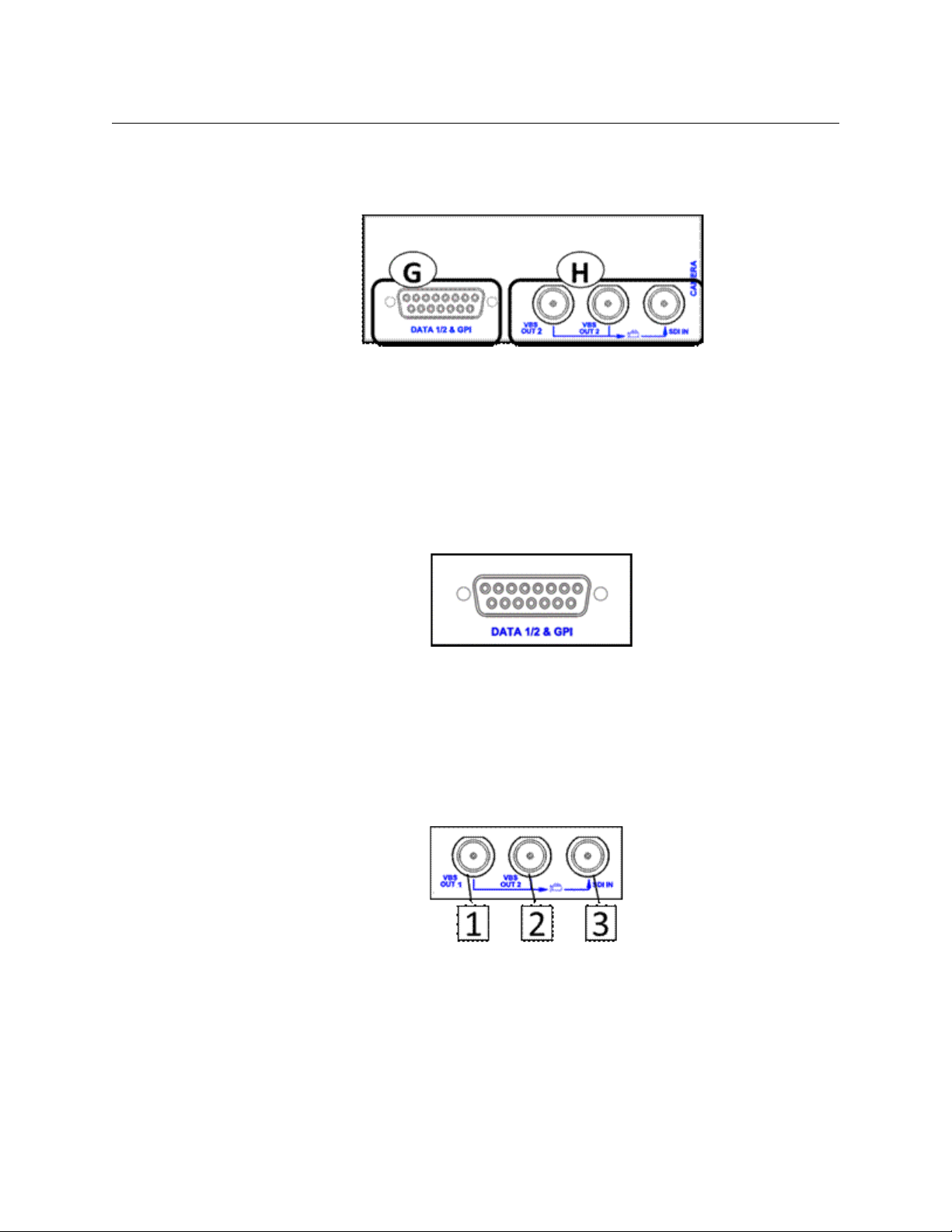
T-POV 301 Camera Unit Rear Panel Detail
The Camera Unit rear panel Area diagram is repeated for reference.
Fig. 3-23: T-POV 301 Camera Unit Rear Panel
The T-POV 301 Camera Unit Rear Panel has three features:
• G: Data/GPI-Tally Connector
• H: Video Connectors
The rear connector panels of all versions of the T-POV 301 Camera Unit are identical in
physical configuration and in function.
Area G - Data/GPI-Tally Connectors
T-POV
User Guide
Fig. 3-24: T-POV 301 Camera Unit Rear Panel -- Area G
DATA 1/2 & GPI - provides up to two bi-directional data feeds and a GPI/Tally connection.
Available data formats are RS232, RS422, and RS485.
For configuration and wiring information on all data & GPI connections please see
Connector Wiring and Connection on page 78.
Area H - Video Connectors
Fig. 3-25: T-POV 301 Camera Unit Rear Panel -- Area H
• 1 & 2 - VBS OUT 1 & 2: video black burst/sync or return video to Camera Unit
• 3 - SDI IN: SDI Video signal coming from Camera Unit
33
Page 40

T-POV 301 Components
T-POV 301 Camera Unit Rear Panel Detail
34
Page 41

T-POV 324 Components
This chapter describes the components in the 324 model of the T-POV Bidirectional Robotic
Camera system.
About the Camera Link System Components . . . . . . . . . . . . . . . . . . . . . . . . . . . . . . . . . . . . . . . . . . 36
T-POV 324 Base Unit . . . . . . . . . . . . . . . . . . . . . . . . . . . . . . . . . . . . . . . . . . . . . . . . . . . . . . . . . . . . . . . . . . 36
T-POV 324 Camera Unit . . . . . . . . . . . . . . . . . . . . . . . . . . . . . . . . . . . . . . . . . . . . . . . . . . . . . . . . . . . . . . 46
35
Page 42

T-POV 324 Components
About the Camera Link System Components
About the Camera Link System Components
The T-POV 324 Robotic Camera Link Base Station and Camera Unit come in both portable
and rack mount configurations. In this chapter, the system components are described using
a single unit rack mounted base station with external 12 Volt power and a standard MiniMussel Shell version of the Camera Unit also with external 12 Volt power.
The variations for the internally powered Base Station and the powered version of the
Camera Unit are described following the 12 Volt versions. Characteristics that are unique to
the two-link 12 Volt Base Stations are also described. The two link rack mounted Camera
Units operate similarly to the two link unit Base Stations.
• T-POV 324 Base Unit on page 36
• T-POV 324 Camera Unit on page 46
T-POV 324 Base Unit
Fig. 4-1: T-POV 324 Base Unit
The T-POV Base Station Front Panel has three features:
• A: Signal Indicator & Optical Power LEDs
• B: Signal Strength & System Setup Display
• C: Power/Status Indicators and Power Switch
Fig. 4-2: T-POV 324 Base Unit
The T-POV Base Station Connector Panel has four features:
• D: Power Section and Fiber Connector(s)
• E: Data/GPI-Tally/Ethernet Connectors
• F: Audio Multi-Pin Connector
• G: Video Connectors
36
Page 43

T-POV 324 Base Unit Front Panel Detail
Icon indicates signal flow
from T-POV Base Station
Unit to Camera Unit
Icon indicates signal flow
from T-POV Camera Unit to
Base Station Unit
Area A - Signal Indicator LEDs
The 16 LED indicators in this area monitor the various signals being sent from the Camera
Unit. LEDs will glow Green when a signal is present.
T-POV
User Guide
Fig. 4-3: Signal Indicator LEDs
• 1: SDI OUT: monitors camera video signal returning from the camera unit
• VBS IN: monitors the black burst/sync signal or return video signal being sent to
the camera
• 2: E'NET: monitors data activity on the Ethernet connection
• DATA 1/2: Monitors data activity on Data Paths 1 and 2
• DATA 3/4: Monitors data activity on Data Path 3
• GPI: Monitors GPI/Tally signal activity
• 3: AUD- monitors audio activity.
All audio is at line level and signals on any of the four
audio channels will activate the LED.
•4: OPT POWER
• Green: indicates that the Optical link between the base station and the camera unit
is locked and functioning.
• Red: indicates there is a problem with the Optical Link at the Base Station.
• Amber: indicates there is a problem at the Camera Unit.
37
Page 44

T-POV 324 Components
T-POV 324 Base Unit Front Panel Detail
Area B - Signal Strength & System Setup Display
• 1: SELECT: selects between three modes of operation. When power is turned on, the
unit defaults to BASE RX display mode
• BASE RX: indicates display mode is Optical Link signal strength received at Base
Station from Camera Unit
• CAM RX: indicates display mode is Optical Link signal strength received at Camera
from Base Station
• DIAGNOSTIC: indicated by Digital Display showing various alphanumeric readouts
(see The T-POV Base Station Digital Display on page 65)
Pushingand holding the SELECT button will enter diagnostics, while a quick push will
return to the base station display. Only base station diagnostics appear on the base
station; you must be at the camera unit for camera unit diagnostics.
The ALARM status (see Area C - Power/Status Indicators and Power Switch on page 39)
will light Amber if there is a problem with the Camera Unit.
• 2: DISPLAY: indicates which unit Optical Link level is being displayed. Neither LED is lit
when the unit is in diagnostics mode.
• 3: Digital Display: indicates Optical Link signal strength in dBm units. Also diagnostic
information when Base Station is in diagnostics modes.
For additional information on both measuring optical link strength and T-POV
diagnostics, see A Brief Guide to Measurement of Fiber Optic Signal Strength on
page 64 and The T-POV Base Station Digital Display on page 65.
Fig. 4-4: Signal Strength & System Setup Display
38
Page 45

Area C - Power/Status Indicators and Power Switch
Fig. 4-5: Power/Status Indicators and Power Switch
• 1: POWER: Power indicator lights Green when the power switch is toggled on.
•2: STATUS
• BASE POWER: indicates the status of all power levels in the Base Station
• Green: all power levels are normal.
• Red: any power level is not normal.
• SYSTEM LOCK: indicates that the Base Station is communicating with the Camera
Unit.
• Green: Base Station is communicating with Camera Unit
• Red: Base Station is not communicating with the Camera Unit
• FIBER LINK: indicates the optical power status of the Base Station and camera
• Green: both the Base Station and camera optical power are within a normal
range.
• Red: both the Base Station and camera optical power are not within a normal
range
• Amber: either the Base Station or camera optical power are not within a
normal range
• ALARM
• Red: there is a temperature, power, hardware or firmware fault in the base unit
system.
• Amber: there is a fault at the Camera Unit.
For more information on these error messages, see The T-POV Base Station Digital
Display on page 65
T-POV
User Guide
39
Page 46

T-POV 324 Components
T-POV 324 Multiple Unit Detail
T-POV 324 Multiple Unit Detail
The T-POV 324 Multiple Unit Base Station differs from the single unit model in that there are
additional LED indicator columns in Area A. Component operation differences are noted
below.
AREA A
The indicator AREA A in the two unit Base Station operates identically to that of a single unit
model (see Area A - Signal Indicator LEDs on page 37). The indicator LEDs monitor their
functions independently of each other.
Fig. 4-6: T-POV 324 Multiple Unit
AREA B
Fig. 4-7: T-POV 324 Multiple Unit Detail -- Area B
SELECT button (1) chooses between three modes of operation and between two or three
camera units, depending on how many camera units are installed in the base station
When the Base Station is powered on, Base Station optical power is displayed.
• The first push of the select button will select CAM 1.
• The second push will select BASE 1.
• The third push will select CAM 2.
• The fourth push will select BASE 2.
• Pushing and holding the SELECT button will enter the diagnostics mode for the device
currently being displayed.
40
Page 47

T-POV 324 Powered Unit Detail
The T-POV 324 Powered Unit base station is delivered with one Optical Link unit. The
physical configuration differs from the 12 Volt model in that the Optical Link unit with its
power supply occupies one-half of the rack mount chassis and the Camera 1 unit is placed
on the left side of the chassis. The term Hybrid Power refers to the integration of 95 Watts of
12 Volt power into the fiber optic cable.
The T-POV Powered Base Station Front Panel has four features:
• A: Signal Indicator LEDs
• B: Signal Strength & System Setup Display
• C: Power/Status Indicators and Power Switch
T-POV
User Guide
Fig. 4-8: T-POV 324 Powered Unit
Area A & B
Areas A and B function identically to that of the 12 Volt version of the T-POV Base Station
(see T-POV 324 Camera Unit Front Panel Detail - 12 Volt Model on page 47). The differences
are in Area C - the Power/Status Indicators and Power Switch.
Area C
Fig. 4-9: T-POV 324 Powered Unit -- Area C
• 1: POWER: lights Red when the AC power main switch on the rear of the unit is turned
on and the front power switch is Off. The indicator lights Green when the front panel
power switch is toggled On.
• With a powered system (power supplied by the Base Station), this switch will
control power to the Camera Unit
• For the hybrid system to be powered on, the AC Mains switch on the rear of Base
Station must be in the on position.
•2: HYBRID POWER INDICATORS
• CAMERA POWER: indicates that high voltage is applied to power the camera.
41
Page 48

T-POV 324 Components
T-POV 324 Powered Unit Detail
• CABLE OPEN: indicates that the high voltage cable is open or there is no high
• CABLE SHORT: indicates that the high voltage cable connected is shorted.
• 3: STATUS INDICATORS
• BASE POWER: indicates the status of all power levels in the Base Station
• SYSTEM LOCK: indicates that the Base Station is communicating with the Camera
• FIBER LINK: indicates the optical power status of the Base Station and camera
• ALARM: indicator will light Red if there is a temperature, power, hardware or
• Green: high voltage is being supplied to the camera.
Off when there is no high voltage applied to the camera
voltage cable connected.
• Green: the cable is properly connected from the Base Station to the camera.
• Red: there no cable connected to the camera, or the cable is connected but
open.
High voltage will not be applied to the camera until the open condition is
corrected.
• Green: all power levels are normal.
• Red: any power level is not normal.
Unit.
• Green: Base Station is communicating with Camera Unit.
• Red: Base Station is not communicating with the Camera Unit.
• Green: both the Base Station and camera optical power are within a normal
range.
• Red: both the Base Station and camera optical power are not within a normal
range
• Amber: either the Base Station or camera optical power are not within a
normal range.
firmware fault in the base unit system. The indicator will light Amber if there is a
fault at the Camera Unit.
• Red: there is a Base Station error. Refer to the Base Station DIAG for details on
the error.
• Amber: there is a camera error. Refer to CAM DIAG for details for the error.
42
Page 49

T-POV 324 Base Unit Rear Panel Detail
The Base Unit rear panel Area diagram is repeated for reference.
Fig. 4-10: T-POV 324 Base Unit Rear Panel
The T-POV Base Station Connector Panel has four features:
• D: Power Section and Fiber Connector(s)
• E: Data/GPI-Tally Connectors & Ethernet
• F: Audio Multi-Pin Connector
• G: Video Connectors
T-POV
User Guide
Area D- Power Section and Fiber Connector(s)
12 Volt models have a single power supply/fiber connection area regardless of the number
of Optical Link units configured.
Fig. 4-11: T-POV 324 Base Unit Rear Panel -- Area D
12 Volt Power Models
• 1: 12V DC External Power Supply input connector (XLR 4 Pin)
For use with an external power supply such as the ADAP-AC-04. See Connector Wiring
and Connection on page 78 for connection details.
• 2: 12V DC Input - terminal block
For use in rack mounted installations as an option to an external "brick" type power
supply. See Connector Wiring and Connection on page 78 for connection details.
• 3: For future use
• 4: ST Connectors
43
Page 50
T-POV 324 Components
T-POV 324 Base Unit Rear Panel Detail
95 Watt Powered Models
Powered models have either one or two AC power/fiber connection areas depending on
the number of optical link units installed.
• 5: AC Power Receptacle: 100-240V 50/60 Hz
• 6: 4 AMP Dual Fuse Assembly: the fuses supplied are standard 4 Ampere fuses - 5 x
20mm. Both fuses are in operation at all times - both the AC Line Hot and the AC Line
Neutral are fused.
• 7: AC Mains Power Switch: this must be turned on for the front panel power switch to
work
• 8: SMPTE 304M Fiber Connector (Powered)
Fig. 4-12: T-POV 324 Base Unit Rear Panel -- 95 Watt Model
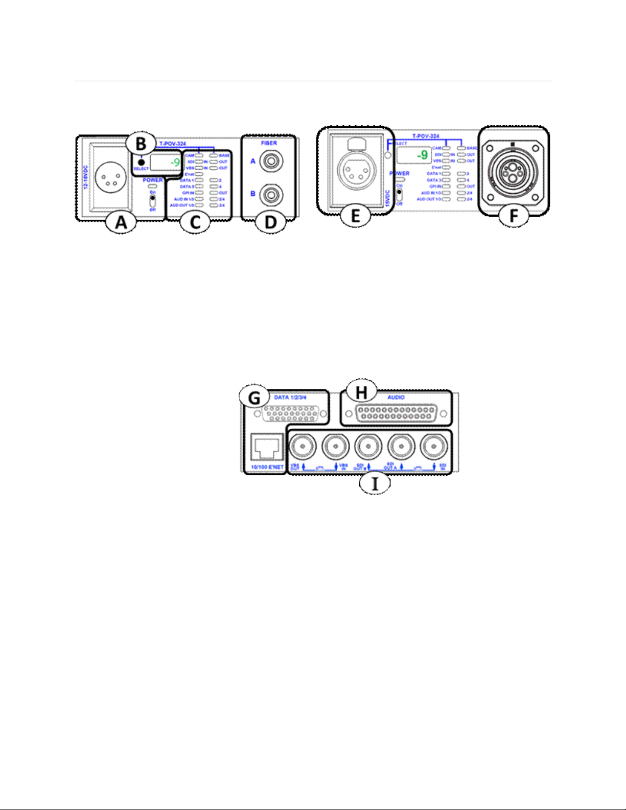
Area E - Data/GPI-Tally Connectors & Ethernet
Fig. 4-13: T-POV 324 Base Unit Rear Panel -- Area E
• 1: DATA 1/2/3/4: provides up to four bi-directional data feeds. Available are Rs232,
RS422 and RS485 data formats.
• 2: 10/100 E'NET: provides an Ethernet connection to the Camera Unit for data or any
network protocol controlled device such as a camera remote control.
Ethernet port is limited to 100BaseT connections. For configuration and wiring
information on all data & GPI connections, see Connector Wiring and Connection on
page 78.
44
Page 51

T-POV
User Guide
Area F - Audio Multi-Pin Connector
Fig. 4-14: T-POV 324 Base Unit Rear Panel -- Area F
AUDIO: multipin connector provides four line level audio signals in to camera unit, and for
four line level audio signals returning from camera unit.
For audio configuration and wiring information connections, see Connector Wiring and
Connection on page 78.
Area G - Video Connectors
Fig. 4-15: T-POV 324 Base Unit Rear Panel -- Area G
• 1: VBS Out: VBS video from Camera Unit
• 2: VBS In: VBS Video feed from Base Station to Camera Unit
• 3 & 4: SDI Out A & B: two SDI outs of Camera video from Camera Unit
• 5: SDI IN: return video feed to Camera Unit from Base Station
45
Page 52
T-POV 324 Components
T-POV 324 Camera Unit
T-POV 324 Camera Unit
The T-POV 324 Camera Unit Front Panel has six features:
• A: Power Section (12 Volt Type)
• B: Optical Power Strength and Diagnostic Display
• C: Signal Indicator LEDs
• D: ST Fiber Connectors
• E: 12-15 VDC Power Output (AC Powered models only)
• F: SMPTE 304M Fiber Connector ("Wet" with 95 Watts of 12 Volt power available)
Fig. 4-16: T-POV 324 Camera Unit Front Panel
46
Fig. 4-17: T-POV 324 Camera Unit Front Panel
The T-POV 324 Camera Unit Rear Panel has three features:
• G: Data & Ethernet Connectors
• H: Audio Multi-Pin Connector
• I: Video Connectors
The T-POV Camera Unit rear panel is identical in the 12 Volt and Powered versions.
Page 53

T-POV 324 Camera Unit Front Panel Detail - 12 Volt Model
Area A - Power Section (12 Volt Type)
Fig. 4-18: T-POV 324 Camera Unit Front Panel -- 12 Volt Model
• 1: POWER: lights Green when the power switch is toggled on.
• 2: 12-18 VDC Power Connection: 4-Pin XLR Female chassis connector for use with an
external power supply (such as the ADAP-AC-04 or equivalent).
Area B - Optical Power Strength and Diagnostic Display
T-POV
User Guide
Fig. 4-19: T-POV 324 Camera Unit Front Panel -- Area B
• 1: DISPLAY SELECT: chooses between three modes of operation.
When power is turned on, the Camera Unit optical power appears first. The first push of
the select button selects the Base Station.
Pushingand holding the SELECT button will enter diagnostics mode, while a quick push
will return to the camera unit display.
• 2: CAM/BASE Indicators: LEDs indicate which unit Optical Power is displayed. Neither
LED is on when the display is in diagnostics mode.
• 3: DISPLAY: optical power is displayed in dBm units and diagnostic information is
alphanumeric. Only Camera Unit diagnostics can be viewed at the Camera Unit (Base
Station diagnostics are not available at the Camera Unit).
For more information on measuring optical power and using system diagnostics, see A
Brief Guide to Measurement of Fiber Optic Signal Strength on page 64 and The T-POV
Base Station Digital Display on page 65.
47
Page 54
T-POV 324 Components
T-POV 324 Camera Unit Front Panel Detail - 12 Volt Model
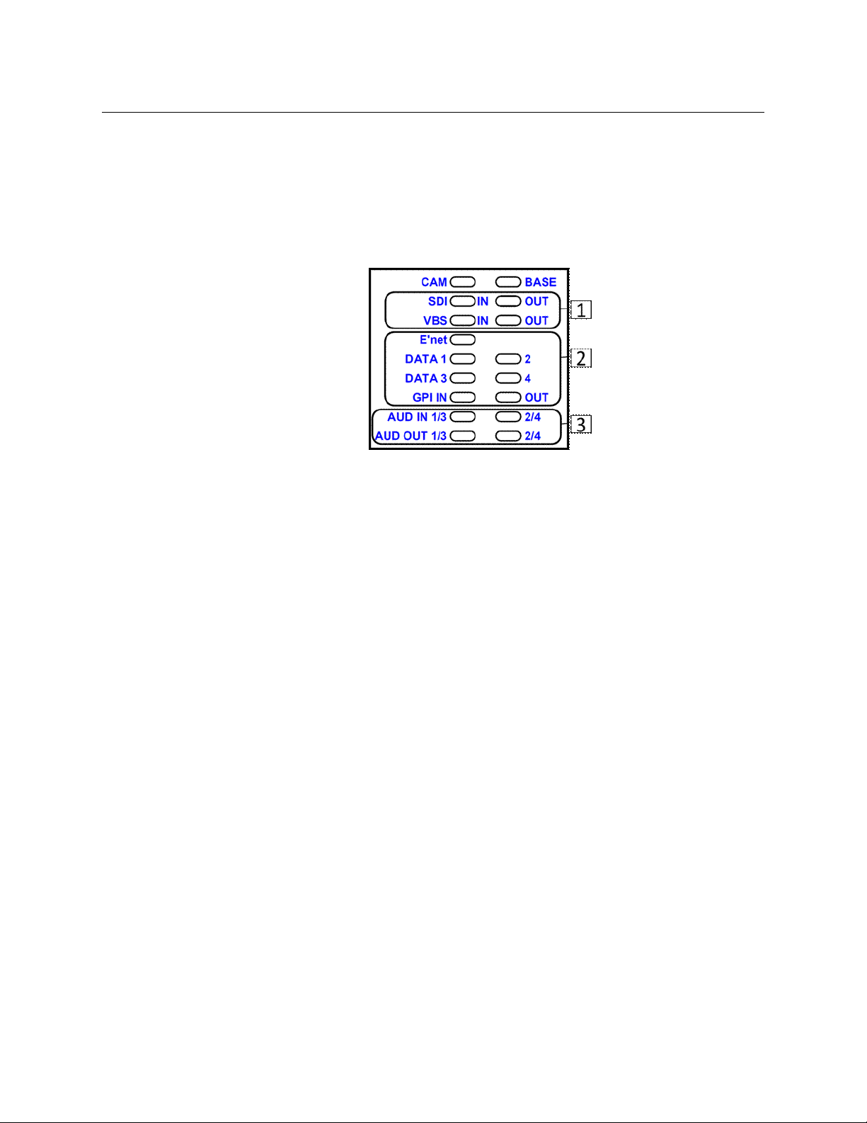
Area C - Signal Indicator LEDs
The 17 LED indicators in this area monitor the various signals being sent to or from the
Camera Unit. LEDs will light Green when a signal is present.
Note: LEDs labeled "IN" indicate signals coming into the camera unit. LEDs labeled "OUT"
indicate signals coming out of the Base Station. If there is neither "IN" or "OUT" associated
with an LED then activity in either the Camera Unit and Base Station is indicated.
Fig. 4-20: T-POV 324 Camera Unit Front Panel -- Area C
• 1: SDI IN & OUT: monitors SDI video signals to and from the Base Station
• VBS IN: monitors the black burst/sync signal or return video signal being sent to
the camera
• VBS OUT: monitors the genlock signal or return video signal being sent to the base
station
• 2: E'NET: monitors data activity on the Ethernet connection
• DATA 1/2: monitors data activity on Data Paths 1 and 2
• DATA 3/4: monitors data activity on Data Path 3
• GPI: Monitors GPI/Tally signal activity
• 3: AUDIO:
• the AUD IN 1/3 and 2/4 LEDs monitor line level audio coming to the Camera Unit
• the AUD OUT 1/3 and 2/4 LEDs monitor line level audio going to the Base Station
48
Page 55

Area D - Fiber Connectors - "Dry" Unpowered Connectors
Fig. 4-21: T-POV 324 Camera Unit Front Panel -- Area D
FIBER CONNECTORS (shown are 2 ST connectors): can be any available unpowered Fiber
Connector depending on user requirements and number of camera units installed. For
additional information, see Fiber Cable Concepts on page 8 and Product Ordering/Model
Information on page 4 regarding ordering information.
T-POV 324 Camera Unit Front Panel Detail - Powered Model
The T-POV 324 Powered Camera Unit receives power from the Base Station over the Hybrid
Fiber Cable connection. The 12 Volt and Powered version of the T-POV 324 operate
identically with two exceptions. The powered version provides a 12-15 Volt output for
camera and accessory power and the Fiber Connection must of necessity be a Hybrid Fiber
Cable connection.
T-POV
User Guide
Area E - 12-15 VDC Power Output
Fig. 4-22: T-POV 324 Camera Unit Front Panel -- Area E
12-15 VDC Power Output: provides up to 95 Watts of 12 Volt power for the camera or
accessories. Please ensure that the total power drain on this source is no more than 95
Watts. For connector wiring information, see Connector Wiring and Connection on page 78.
49
Page 56

T-POV 324 Components
T-POV 324 Camera Unit Rear Panel Detail
Area F - Fiber Connector
Fig. 4-23: T-POV 324 Camera Unit Front Panel -- Area f
Fiber Connector: SMPTE 304M Hybrid power fiber connection carries signals to and from
the Base Station and 95 Watts of12 Volt power from the base station.
T-POV 324 Camera Unit Rear Panel Detail
The Camera Unit rear panel Area diagram is repeated for reference.
Fig. 4-24: T-POV 324 Camera Unit Rear Panel Detail
The T-POV 324 Camera Unit Rear Panel has three features:
• G: Data & Ethernet Connectors
• H: Audio Multi-Pin Connector
• I: Video Connectors
The rear connector panels of all versions of the T-POV 324 Camera Unit are identical in
physical configuration and in function.
50
Page 57

Area G - Data/GPI-Tally Connectors
Fig. 4-25: T-POV 324 Camera Unit Rear Panel Detail -- Area G
• 1: DATA 1/2/3/4: provides up to four bi-directional data feeds. Available are Rs232,
RS422 and RS485 data formats.
• 2: 10/100 E'NET: provides an Ethernet connection to the Base Unit for data or any
network protocol controlled device such as a camera remote control.
Ethernet port is limited to 100BaseT connections. For configuration and wiring
information on all data & GPI connections, see Connector Wiring and Connection on
page 78.
T-POV
User Guide
Area H - Audio Multi-Pin Connector
Fig. 4-26: T-POV 324 Camera Unit Rear Panel Detail -- Area H
AUDIO: multipin connector provides for four line level audio signals in to camera unit and
for four line level audio signals returning from camera unit.
For configuration and wiring information on audio connections, see Connector Wiring and
Connection on page 78.
Area I - Video Connectors
Fig. 4-27: T-POV 324 Camera Unit Rear Panel Detail -- Area I
• 1: VBS Out: VBS video from Camera Unit
• 2: VBS In: VBS Video feed from Base Station to Camera Unit
• 3 & 4: SDI Out A & B: two SDI outs of Camera video from Camera Unit
• 5: SDI IN: return video feed to Camera Unit from Base Station
51
Page 58

T-POV 324 Components
T-POV 324 Camera Unit Rear Panel Detail
52
Page 59

Connecting the T-POV System
Prior to connecting your T-POV Robotic Camera Link System, please ensure that each of the
required cables is available for use.
This includes standard video, audio and data cables as well as custom multi-pin cable sets
required for your particular installation. Please see the Connector Wiring and Connection
on page 78 for information regarding cables and connectors.
T-POV Usage Scenarios . . . . . . . . . . . . . . . . . . . . . . . . . . . . . . . . . . . . . . . . . . . . . . . . . . . . . . . . . . . . . . . 54
Connections to the T-POV Base Station . . . . . . . . . . . . . . . . . . . . . . . . . . . . . . . . . . . . . . . . . . . . . . . 57
Connections to the T-POV Camera Unit . . . . . . . . . . . . . . . . . . . . . . . . . . . . . . . . . . . . . . . . . . . . . . . 59
53
Page 60

Connecting the T-POV System
T-POV Usage Scenarios
T-POV Usage Scenarios
The three scenarios shown represent a small cross-section of the various available
configurations. Please consider these scenarios as samples of how a system might be used
in a real-world application.
The following fiber connection scenarios do not take into account any customized cable
and connector installations you may have at your facility. For assistance regarding more
complex connection situations, contact Grass Valley (see Contact Us on page 77) or your
local authorized dealer.
Tactical Fiber between the Base Station and Camera Unit
54
Fig. 5-1: Tactical Fiber between the Base Station and Camera Unit
Between the Base Station (A) the Camera Unit (B) is a length of Tactical Fiber Cable (C). At
each end of the fiber cable are a set of two ST Connectors.
The Camera Unit and the Base Station are powered by an external 12 Volt power supply (D).
The recommended ADAP-AC-04 is illustrated. The Camera connected to the Camera Unit
must have its own separate power source.
Connected to the Base Station is a Camera Control Unit (CCU) with camera controls and
remote pan and tilt controls (F). Depending on the control unit requirements the
connection to the base station will be either a serial data connection or an Ethernet
connection.
Connected to the Camera Unit is a remote HD Camera (E) mounted on a remotely
controlled pan and tilt unit. Typically the camera will be connected to the T-POV Camera
Unit by an HD-SDI BNC cable and the pan and tilt unit will be connected through either a
serial data connection or an Ethernet Connection.
Page 61

Two Link Unit Installation with Tactical Fiber
T-POV
User Guide
Fig. 5-2: Two Link Unit Installation with Tactical Fiber
This scenario is functionally idential to the first usage scenario with the addition of an
added Camera Unit and CCU/Remote Pan & Tilt unit. One 2-Link Unit Base Station (A) is
connected by Fiber Cable to two separate Camera Units (B). The Camera Unit connections
begin with Unit 1 on the left next to the Power and Fiber Connector module. Unit 2 is to the
right of Unit 1.
The Camera Units in this example use two ST connectors each. The Base Station and each
Camera Unit are powered by an ADAP external 12 Volt power supply (D).
This example shows two identical Cameras (E) connected to the Camera Units. This is
illustrative only and a real-world installation could have two different camera types if
required. This example shows two individual Camera Control: Remote Pan & Tilt units (F). A
common CCU could be used if it provides a separate data connection for each of the
remote cameras.
55
Page 62

Connecting the T-POV System
Hybrid Fiber between the Base Station and Camera Unit
Hybrid Fiber between the Base Station and Camera Unit
Fig. 5-3: Hybrid Fiber between the Base Station and Camera Unit
Between the Base Station (A) the Camera Unit (B) is a length of Hybrid Fiber Cable (C). The
maximum length of this hybrid cable is 240 meters. The cable is deployed from a fiber reel.
At each end of the fiber cable is a "wet" SMPTE 304M Fiber Connector carrying 12 Volts of
power.
The Base Station is powered by an internal AC power supply (D). The Camera Unit is
powered through the Hybrid Fiber Cable. The Camera (E) connected to the Camera Unit can
either be powered from the external power connection on the T-POV Camera Unit or from
its own local power supply. If the camera is powered from the T-POV, the total power
budget must not exceed a total of 95 Watts.
Connected to the Base Station is a Camera Control Unit (CCU) with camera controls and
remote pan and tilt controls (F). Depending on the control unit requirements, the
connection to the base station will be either a serial data connection or an Ethernet
connection (T-POV 324 only).
56
Page 63

Connections to the T-POV Base Station
T-POV 301 Base Station Connectors
T-POV 324 Base Station Connectors
T-POV Powered Base Station Connectors
This section provides details on both the connectors and signal types that can be applied to
the T-POV Base Stations(T-POV 301 and 324 are illustrated). In the list of connections, it is
noted which connections are applicable to the various T-POV models.
T-POV
User Guide
Item Description
1 & 15 Power In
2 12V Terminal Block
3 MON - RJ45 Network Type Connection
4 & 16 Fiber Connector
Fig. 5-4: T-POV Base Station
Connect a standard 12V DC ADAP power source (4 Pin) or a standard 3
conductor AC Cable (IEC Plug) 100-240V 50/60 Hz
Applies to all models depending on power type.
The bare wire connector can be used in place of the ADAP power connection in
installations that have 12V power distributed as part of their infrastructure. Do
not use this at the same time as the ADAP power connection.
Applies only to 12 Volt models - does not apply to AC powered types
For Future Use
Applies to all models
Connect the fiber connector from the Fiber Cable connected to the Camera
Unit. The type of fiber connector depends on whether the system is 12 Volt or
internally powered.
Applies to all models.
Note: Power to the Base Unit (and the Camera Unit) must be turned off when
connecting the Camera Remote Control Panel. Connecting with the power on
can seriously damage your equipment.
57
Page 64

Connecting the T-POV System
Connections to the T-POV Base Station
Item Description
5 Data 1/2 & GPI
DB15: 15 Pin data connector. Used for a variety of serial connections or GPI/Tally
connections. The Camera Control Unit and Pan & Tilt Control is one such data
connection.
Applies to T-POV 301
6 & 11 VBS IN
BNC Connector: typically used to send a Genlock/Black Burst signal or SD return
video to the camera (ex.: monitor out from the Production Switcher).
Applies to all models
7 & 12 SDI Out 1 & 2 or A & B (this carries the HD feed from the camera)
BNC Connectors: two identical video feeds from the camera unit - typically one
may be used for local HD monitoring and one is fed to the Production Switcher
environment.
Applies to all models
8 DATA/GPI
DB26: 26 Pin data connector. Used for a variety of serial connections or GPI/Tally
connections. The Camera Control Unit and Pan & Tilt Control is one such data
connection.
Applies to T-POV 324
9 Ethernet Connector - 10Bt/100Bt capable
Designed to carry IP traffic data between the Base Station and the Camera Unit.
Can be used to control Ethernet based Camera and Pan & Tilt equipment. Also a
laptop PC or other device such as a Wireless Access Point can be connected to
the Production Environment IP network.
Applies to T-POV 324
10 VBS Out
BNC Connector: carries SD Analog video from the Camera Unit to the Base
Station. Typically this will feed a Camera SD menu monitor feed.
Note: An HD signal can be sent through the VBS path but the system will only
pass SD quality.
Applies to T-POV 324
13 SDI In
BNC Connector: typically used to send HD return video to the camera (ex.:
program out from the Production Switcher).
Applies to T-POV 324
14 Audio
DB25: 25 Pin connector. Connector follows the Tascam TDIF standard. Up to
four channels of line level audio in and out can be connected.
Applies to T-POV 324
58
Page 65

Connections to the T-POV Camera Unit
T-POV 301 Camera Unit
T-POV 301 Camera Unit
T-POV 301 Camera Unit
T-POV 301 Camera Unit
This section provides details on both the connectors and signal types that can be applied to
the T-POV Camera Units (T-POV 301 and 324 are illustrated). In the list of connections, it is
noted which connections are applicable to the various T-POV models.
T-POV
User Guide
Item Description
1 Data 1/2 & GPI
DB15: 15 Pin data connector. Used for a variety of serial connections or GPI/Tally
connections.
Applies to T-POV 301
2 & 5 VBS Out
BNC Connector: typically used to send a Genlock/Black Burst signal or SD return
video to the camera (ex.: monitor out from the Production Switcher).
Applies to all models
3 & 8 SDI In
BNC Connectors: HD Video feed from the camera unit to the base station typically this is fed to the Production Switcher or primary monitoring
environment.
Applies to all models
Fig. 5-5: T-POV 301 and 324Camera Unit
59
Page 66

Connecting the T-POV System
Connections to the T-POV Camera Unit
Item Description
4 Ethernet Connector - 10Bt/100Bt capable
Designed to carry IP traffic data between the Base Station and the Camera Unit.
Can be used to control Ethernet based Camera and Pan & Tilt equipment. Also a
laptop PC or other device such as a Wireless Access Point can be connected to
the Production Environment IP network.
Applies to T-POV 324
6 VBS In
BNC Connector: carries SD Analog video from the Camera Unit to the Base
Station. Typically this will feed a Camera SD menu monitor feed.
Applies to T-POV 324
7 SDI Out A & B
BNC Connector: typically used to send HD return video to the camera (ex.:
program or aux bus out from the Production Switcher).
Applies to T-POV 324
9 DATA 1/2/3/4
DB26: 26 Pin data connector. Used for a variety of serial connections or GPI/Tally
connections. The Camera Control Unit and Pan & Tilt Control is one such data
connection.
Applies to T-POV 324
10 Audio
DB25: 25 Pin connector. Connector follows the Tascam TDIF standard. Up to four
channels of line level audio in and out can be connected.
Applies to T-POV 324
11 Power In
Connect a standard 12V DC ADAP power source (4 Pin).
Applies to all models that have external power.
12 & 14 Fiber Connector
Connect the fiber connector from the Fiber Cable connected to the Camera Unit.
The type of fiber connector depends on whether the system is 12 Volt or
internally powered.
Applies to all models
13 Power Out
Provides a standard 12V DC power source (4 Pin). Total power available including
that used by Camera Unit is 95 Watts.
Applies to all models that have external power.
60
Page 67

Operation of the T-POV System
This chapter describes in detail the operation of T-POV Robotic Camera Link System. Keep
in mind that a wide variety of options and variations are available in using this product and
so not every possible operational environment can be described.
Variations in camera type, battery and powering, fiber cable connections allow for an
enormous number of slightly different operational modes.
Set Up Of The T-POV Robotic Camera Link System For Operation . . . . . . . . . . . . . . . . . . . . . . 62
Powering the System . . . . . . . . . . . . . . . . . . . . . . . . . . . . . . . . . . . . . . . . . . . . . . . . . . . . . . . . . . . . . . . . . 63
A Brief Guide to Measurement of Fiber Optic Signal Strength . . . . . . . . . . . . . . . . . . . . . . . . . . 64
The T-POV Base Station Digital Display . . . . . . . . . . . . . . . . . . . . . . . . . . . . . . . . . . . . . . . . . . . . . . . 65
Best Practices . . . . . . . . . . . . . . . . . . . . . . . . . . . . . . . . . . . . . . . . . . . . . . . . . . . . . . . . . . . . . . . . . . . . . . . . 71
Shutting Down the System . . . . . . . . . . . . . . . . . . . . . . . . . . . . . . . . . . . . . . . . . . . . . . . . . . . . . . . . . . . 72
Troubleshooting . . . . . . . . . . . . . . . . . . . . . . . . . . . . . . . . . . . . . . . . . . . . . . . . . . . . . . . . . . . . . . . . . . . . . 72
61
Page 68

Operation of the T-POV System
Set Up Of The T-POV Robotic Camera Link System For Operation
Set Up Of The T-POV Robotic Camera Link System For Operation
This section provides a high-level overview of setup of the T-POV Robotic Camera Link
System for operation. The following sections provide additional detail on each aspect of
setup and operation.
It is important that you do an initial setup and test of your T-POV Robotic Camera Link
System for operation as soon as your receive it to confirm proper operation and to provide
training for you and your team prior to an actual production.
It is highly recommended that you do not attempt to power up the system until all
connections are made, in particular that the Fiber Optic Cable has been connected at both
ends. If you need to power up either the T-POV Robotic Camera Link Base Station or Camera
Unit, make sure that the Fiber Connectors are securely capped. This will protect
theseconnectors from damage or dirt and protect you from damaging your eyes.
The order in which you connect the cables makes no difference. Make sure to connect the
Camera Remote Control cable to the Base Station and Remote Control Panel when the Base
Station power is turned off.
Make sure to connect the Camera Remote Control cable to the Camera Unit and Camera
when the Camera power is turned off.
Once you deploy the Fiber Cable, you are now ready to Power Up the system.
You should read the Using Fiber Optics Guide for information on how to manage and
deploy your fiber optics cabling, safety precautions, tips & tricks, and recommendations for
creating complex fiber optic networks. You can find a copy of this document on the
Support portal (see Contact Us on page 77).
62
Page 69

Powering the System
The T-POV Base Station and the T-POV Camera Unit each have a power up routine which
tests the equipment and performs a system diagnostic.
Powering the T-POV Base Station
To power up the T-POV Base Station
1 Base Station Main Power: for externally powered Base Stations plug in the power
supply.
For internally powered Base Station, connect the unit to the AC Mains and turn on the
Base Station Power Mains Switch located at the rear left (when facing the back of the
Base Station) of the unit. The front panel power light will light Red until the next step.
2 Base Station Power: Turn on the Front Panel Power Switch located at the front right.
For internally (AC) powered units, the power monitor indicator changes from Red to
Green.
3 Four Character Display LED Indicator progression: The 4-character display indicates
TEST and all front panel LEDs change from Red to Greento Amber, and then off.
4 REV display: The LED color test is followed by REV and the revision of the display
microcontroller firmware.
5 Scrolling: The REV indication is followed by "miranda.com" scrolling across the 4-
character display. If there's no scrolling, contact Grass Valley support for assistance (see
Contact Us on page 77).
6 PAU SE : The scroll is followed by about a three second interval used to synchronize all
the microcontrollers in the Base Station
7 Current Status Displayed: After the three second pause, each of the entire front panel
LEDs update with current status. If the Camera Unit is not powered on the camera,
status lights will light Red.
T-POV
User Guide
Powering the T-POV Camera Unit
To power up the T-POV Camera Unit
1 Camera Unit power: turn on the Camera Unit Power Switch
2 Camera Power: turn on the Camera Power and also any peripheral equipment
connected to the camera or the T-POV Camera Unit such as monitors and microphones.
3 Four Character Display LED Indicator progression: onceyou turn on the power, the 4-
character display indicates the current Revision Version (REVA). Your unit will reflect the
current Revision Version. After the revision display, the current Fiber Link strength
appear. A typical display is -8 to -13, which indicates Fiber link strength of from -8 to -13
dBm.
63
Page 70
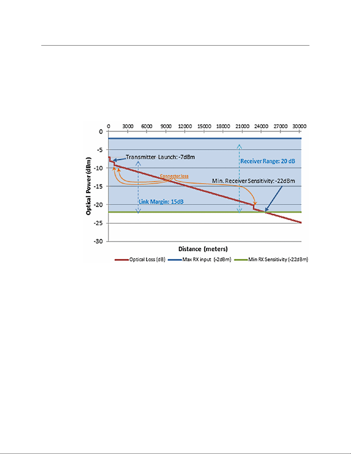
Operation of the T-POV System
A Brief Guide to Measurement of Fiber Optic Signal Strength
A Brief Guide to Measurement of Fiber Optic Signal Strength
The T-POV Optical Link System operates within a defined fiber optic link margin, based on
two factors:
• Output (or "launch") power of the optical transmitter at each end of the link: typically
-7dBm*
• Sensitivity of the optical detector at each end of the link: typically -22 dBm.
The following diagram illustrates the Fiber Link transmission range related to Optical Power
64
Fig. 6-1: T-POV Fiber Optic Link Margin
The overall link margin (or dynamic range) of the T-POV system (the difference between the
transmitter's output power and the receiver's sensitivity) is typically 15dB.
That margin is consumed by two main factors:
• Optical loss over the length of the fiber cable: typically 0.5dB per kilometer
• Optical loss at connection points: typically 1 dB per connector
Therefore, a Tactical Fiber T-POV system can optimally work over 24 kilometers of cable
(spending 12 dB of the link budget), and three connectors (spending 3 dB of the budget).
The T-POV Transceiver System provides direct digital readout of the Fiber Optic Link signal
strength for both the Base-to-Camera link and the Camera-to-Base link.
*The unit "dBm" is an abbreviation for the optical power measured in decibels referenced to
one milliwatt (mW).
Page 71

The T-POV Base Station Digital Display
The digital readouts on both the T-POV Base Station and Camera Unit provide direct signal
strength measurements in dBm. These readouts also provide a wide range of diagnostic
information. The use of the digital readouts is described in this section.
The Base Station digital display has three functions selected by the Display Mode SELECT
button. These functions are indicated by the Display Mode LEDs.
• BASE RX: Base Station Optical Power or Signal Strength that is being received at the
Base Station. Displayed in units of -dBm. The acceptable range for operation is -7dBm
down to -22dBm. *
• CAM RX: Optical Power or Signal Strength being received at the Camera Unit (displayed
in units of -dBm). The acceptable range for operation is -7dBm down to -22dBm. *
• DIAG: one of four diagnostics modes:
• TEMP: displays operating temperature in degrees Centigrade of each circuit board
that reports temperature
• POWR: displays power level from monitored circuit boards
• REV: displays microcontroller firmware version from each circuit board with a
microcontroller
• CAM: displays the error status reported by the Portable Unit
T-POV
User Guide
To select the different display modes, push the SELECT button. The transition from one
mode to another may take a moment, with the transition into the DIAG mode taking
slightly longer. The Selector is cyclicaland rotates through each of the modes. Once in the
DIAG mode, a quick push of the SELECT button cycles through the various diagnostic submodes described above.
Diagnostic Display Modes
The following table describes the sequence, abbreviations, and expected readouts in each
of the display modes.
Display Mode Readout Base Station Digital Display Activity Explanation
(assumes after initial power up: see Powering the System on page 63 for a description of
the Power Up sequence)
BASE RX (Base Station Receive Signal Strength)
BASE RX -9 Indicates tha‘t the Base Station signal strength is -9 dBm
CAM RX (Portable Unit Receive Signal Strength)
CAM RX -9 Indicates that the signal strength from the Portable Unit is -
9 dBm
The display will cycle between "COPT" (Camera Optical) and
"BOPT" (Base Optical) before/after the numerical optical
Power Reading.
DIAGNOSTIC MODE Temperature (TEMP)
65
Page 72

Operation of the T-POV System
Diagnostic Display Modes
Display Mode Readout Base Station Digital Display Activity Explanation
DIAG When first entering the Diagnostic mode the
DIAG/TEMP TEMP Indicates the display is in the TEMP sub-mode
DIAG/TEMP PS The Power Supply (PS) temperature will be displayed
DIAG/TEMP TEMP Repeats that the display is in the TEMP sub-mode
DIAG/TEMP 37C Temperature display in Centigrade for Power Supply circuit
DIAG/TEMP BASE The Base Station main circuit board temperature will be
DIAG/TEMP TEMP Repeats that the display is in the TEMP sub-mode
DIAG/TEMP 47C Temperature display in Centigrade for Base Station circuit
DIAG/TEMP PS The Power Supply (PS) temperature will be again displayed
DIAG/TEMP TEMP Repeats that the display is in the TEMP sub-mode
DIAG/TEMP 36C Temperature display in Centigrade for Power Supply circuit
DISPLAY indicator LED will blink - the first sub-mode
displayed on the digital readout is TEMP (Temperature).
board
displayed
board
board NOTE: that the PS temperature has dropped one
degree
This display cycle repeats until the Display Mode Selector is
pushed
DIAGNOSTIC MODE Power Supply Voltage Status (POWER)
DIAG/POWER A quick push of the Display Mode Selector advances to the
Power (POWR) diagnostic sub-mode.
DIAG/POWER POWR Indicates the display is in the POWER sub-mode
DIAG/POWER BASE Indicates that the Base Station main controller board is
being measured
DIAG/POWER POWER Indicates the display is in the POWER sub-mode
DIAG/POWER OK Indicates that the item is in an OK State
DIAG/POWER DISP Indicates that the LED Display controller board is being
measured
DIAG/POWER POWER Indicates the display is in the POWER sub-mode
DIAG/POWER OK Indicates that the item is in an OK State
DIAG/POWER CHAR Indicates that the Four Character controller board is being
measured
DIAG/POWER POWR Indicates the display is in the POWER sub-mode
DIAG/POWER OK Indicates that the item is in an OK State
DIAG/POWER AUD Indicates that the Audio controller board is being measured
DIAG/POWER POWR Indicates the display is in the POWER sub-mode
DIAG/POWER OK Indicates that the item is in an OK State
66
Page 73

T-POV
User Guide
Display Mode Readout Base Station Digital Display Activity Explanation
DIAG/POWER VBS Indicates that the VBS (analog Video) controller board is
being measured
DIAG/POWER POWR Indicates the display is in the POWER sub-mode
DIAG/POWER OK Indicates that the item is in an OK State
DIAG/POWER Exception
DIAG/POWER ERR Instead of OK, the display will show ERR if a power level is
outside of normal - ERR is followed by a Hexadecimal code.
Please note the error code and contact support (see
Contact Us on page 77).
DIAGNOSTIC MODE Microcontroller Board Revision Version (REV)
DIAG/REV A quick push of the Display Mode Selector advances to the
Power (POWR) diagnostic sub-mode. This sub-mode
displays the microcontroller firmware revision of every
board in the Base Station that has a microcontroller.
DIAG/REV REV Initial display of REV after Display Mode Selector being
advances
DIAG/REV DISP Indicates the Display microcontroller board is revision is
being queried
DIAG/REV REV Indicates that sub-mode is REV
DIAG/REV REVC Indicates that the REV for the DISP board is REVC
DIAG/REV VBS Indicates the VBS microcontroller board is revision is being
queried
DIAG/REV REV Indicates that sub-mode is REV
DIAG/REV REVA Indicates that the REV for the VBS board is REVA
DIAG/REV BASE Indicates the Base Station main microcontroller board is
revision is being queried
DIAG/REV REV Indicates that sub-mode is REV
DIAG/REV REVA Indicates that the REV for the BASE board is REVA
DIAG/REV AUD Indicates the audio microcontroller board is revision is
being queried
DIAG/REV REV Indicates that sub-mode is REV
DIAG/REV REVA Indicates that the REV for the AUD board is REVA measured -
applicable 324 model (Your Revision may differ)
DIAG/REV PS Indicates the power supply microcontroller board is revision
is being queried
DIAG/REV REV Indicates that sub-mode is REV
DIAG/REV REVD Indicates that the REV for the DISP board is REVD (Your
Revision may differ)
This display cycle repeats until the Display Mode Selector is
pushed
67
Page 74

Operation of the T-POV System
The T-POV Portable Unit Digital Display
Display Mode Readout Base Station Digital Display Activity Explanation
DIAGNOSTIC MODE Camera Unit Error Status (CAM)
A quick push of the Display Mode Selector advances to the
Portable Unit (CAM) diagnostic sub-mode. This mode
displays the error status of the Portable Unit. The Digital
Display Characters are Green if Portable Unit shows no error
and Red if the Portable Unit does have an error. This is a
high-level view of the Portable Unit error status.
For further information go to the Portable Unit diagnostic
display.
DIAG/CAM CAM Indicates that the sub-mode is CAM
DIAG/CAM OK Indicates that the Portable Unit is reporting No fault
DIAG/CAM ERR Indicates that the Portable Unit is reporting Some fault
This display cycle repeats until the Display Mode Selector is
pushed
The T-POV Portable Unit Digital Display
The Portable Unit Digital Display has six functions selected by the Display Selector.
• COPT: displays the Camera Unit Optical Power or Signal Strength (Camera OPTical) that
is being generated at the Portable Unit and sent to the Base Station. Displayed in units
of -dBm.
• BOPT: displays the Optical Power (Base OPTical) or Signal Strength generated by the
Base Station as measured at the Portable Unit. Displayed in units of -dBm.
• TEMP: displays operating temperature in degrees Centigrade of each circuit board that
reports temperature
• POWR: displays power level from monitored circuit boards
• REV: displays microcontroller firmware version from each circuit board with a
microcontroller
To select the different display modes push the Display Selector. The transition from one
mode to another may take a moment. The Selector is cyclical rotating through each of the
modes.
The following table describes the sequence, abbreviations, and expected readouts in each
of Portable Unit's alpha-numeric display modes.
Readout Portable Unit Digital Display Activity Explanation
(assumes after initial power up: see Powering the System on page 63 for a description of
the Power Up sequence)
COPT (Portable Unit Optical Signal Strength)
68
COPT Indicates that the Display is showing the optical signal strength at the
Portable Unit
-9 Indicates that the Portable Unit signal strength is -9 dBm
BOPT (Base Station Signal Strength)
Page 75

T-POV
User Guide
Readout Portable Unit Digital Display Activity Explanation
BOPT Sequence starts with BOPT to indicate the optical signal strength at the
Base Station
-9 Indicates that the signal strength being received at the Base Station is -9
dBm
This display cycle repeats until interrupted by the BASE Rx/DIM button. . A
quick push of the BASE Rx/DIM button returns to the COPT mode A longer
push (approximately 5 seconds) advances to DIAG mode.
DIAGNOSTIC MODE Power (POWR)
Holding the SELECT button for approximately five seconds advances to the First
diagnostic mode, which is POWR status. This mode cycles through the following
sequence and may start at any point in the cycle.
LBUS Indicates that the LBUS controller board is being measured
POWR Indicates the display is in the POWER sub-mode
OK Indicates that the item is in an OK State
UBUS Indicates that the UBUS controller board is being measured
POWR Indicates the display is in the POWER sub-mode
OK Indicates that the item is in an OK State
OBOX Indicates that the Audio Interface Box controller board is being measured -
applicable to 324 model
POWR Indicates the display is in the POWER sub-mode
OK Indicates that the item is in an OK State
MAIN Indicates that main Portable Unit controller board is being measured
POWR Indicates the display is in the POWER sub-mode
OK Indicates that the item is in an OK State
DIAGNOSTIC MODE Microcontroller Board Revision Version (REV)
A quick push of the SELECT button from PWR mode advances to the REV mode. This
mode displays the microcontroller firmware revision of every board in the Portable Unit.
This mode cycles through the following sequence and may start at any point in the cycle.
REV Indicates that mode is REV
OBOX Indicates the OBOX microcontroller board is revision is being queried -
applicable to and 324 model
REVD Indicates that the REV for the Audio Interface Box board is Revision "D" -
Your revision may differ
REV Indicates that mode is REV
MAIN Indicates the BASE microcontroller board is revision is being queried
REVD Indicates that the REV for the BASE Portable Unit controller board is
Revision "D" - Your revision may differ
REV Indicates that mode is REV
UBUS Indicates the UBUS microcontroller board is revision is being queried
69
Page 76

Operation of the T-POV System
The T-POV Portable Unit Digital Display
Readout Portable Unit Digital Display Activity Explanation
REVD Indicates that the REV for the UBUS board is Revision "D" - Your revision
DIAGNOSTIC MODE Temperature (TEMP)
A quick push of the SELECT button from REV mode advances to the TEMP mode. This
mode displays the internal temperature (in degrees centigrade) of the Portable Unit.
This mode cycles through the following sequence and may start at any point in the cycle.
TEMP Sequence starts with TEMP to indicate Temperature Display mode
MAIN The Portable Unit MAIN controller board temperature will be displayed
61C Temperature display in Centigrade for Portable Unit main circuit board
may differ
70
Page 77

Best Practices
When using the laser equipment, take special precautions to prevent damaging your eyes.
Protect the Fiber Optic Cable and the Fiber Optic Connectors. Always keep these item
capped until they are being connected.
Once the system is set up and running, payclose attention to the Optical Power Signal
Strength Readouts at either the Camera Unit or the Base Station. While the Alarm functions
of the system are very good, so is the tolerance for optical Signal Strength reduction. By
monitoring -dBm levels, you can take preventative action to stop a signal and possibly an
On-Air or Recording loss. The system is digital, so the Signal Strength either meets or
exceeds requirements.. When it is no longer strong enough, the signal stops.
If introducing new equipment (cameras, switchers, etc.) or new operators, perform a realworld test run as it would be during the actual production. A hands-on experience is the
best way to understand how it works and what to do to ensure proper operation.
Be as careful during System tear down as with System setup.
Read the Using Fiber Optics Guide for information on how to manage and deploy your
fiber optics cabling, safety precautions, tips & tricks, and recommendations for creating
complex fiber optic networks. You can find a copy of this document on the Support portal
(see Contact Us on page 77).
T-POV
User Guide
71
Page 78

Operation of the T-POV System
Shutting Down the System
Shutting Down the System
System shutdown is simple. Take special care whenhandling the Fiber Cable and to the
Camera Remote Control Panel Cable.
Camera Power and Camera Unit Power may be turned off at any time. If your system uses
Hybrid Power, these are same features.
• To prevent looking directly into an active fiber optic port or cable, turn both the
Camera Unit and the Base Station off before disconnecting the fiber from either point.
• To prevent damaging the Camera or Camera Remote Control Panel, turn both the
Camera Unit and the Base Station off before disconnecting the Control Cable from the
Control Panel, the Base Station, the Camera Unit, or the Camera itself.
• Protect all cables from dirt, water entry, and from being dragged across the ground or
other surfaces.
• When re-spooling the cable, avoid cable snags, crimps, or damage to the connectors.
Re-spool evenly across the reel.
• If the Base Station is a permanent or semi-permanent installation, power off and
disconnect and cap the Fiber Cable.
Troubleshooting
Troubleshooting any technical issues with the T-POV Robotic Camera Link System is similar
to any piece of television production gear with the obvious exception of the core Fiber
Optic technology.
• Check all your cables forany broken connections or bad connectors.
• Ensurethat the Power Supplies are working.
• If the Base Station is internally-powered, ensurethat the main switch on the rear
panel turned on.
• Check the fuses. If the system is internally powered, ensure that you are within the
95 Watt limit on power consumption.
• Use the various diagnostic tools provided in the T-POV Robotic Camera Link Base
Station and Camera Unit.
• Ensurethat the Fiber Optic Signal Strength within an acceptable range. The product
specification calls for strength of -22 dBm or greater. but the system will often work
at strengths lower than this,althis is not guaranteed.
Use the Four-Character Digital Displays to monitor signal strength. Remember to
check both local and remote power in case that the Base Station is putting out
good power, but the Camera Unit is not receiving it.
• Observe all of the LED warning and alarm lights on the Base Station and follow up
with the appropriate action.
• If signal strength is degraded from the time of system checkout at a particular
location, walk the Fiber Cable verify that it is in intact and has no damage, no
severe bends, or no kinks.
• If the digital display indicates an error and displays a Hexadecimal error code, you
should contact Grass Valley support to assist in diagnosing the problem (
on page 77
see Contact Us
).
72
Page 79

Note: The exact error code so you can report it to support. The
hexadecimal errors indicate problems with the power supplies and
the internal boards. In general, there is not much you can do as an end
user if one of these rare error messages is displayed.
T-POV
User Guide
73
Page 80

Operation of the T-POV System
Troubleshooting
74
Page 81

Specifications
Video, Digital
Interface ..............................................................................................................SMPTE 259M, 292M
Data Rate...........................................................................................................270 Mb/s or 1.5 Gb/s
Input Level..................................................................................................... 800mV (peak to peak)
Input Impedance .................................................................................................................. 75 Ohms
Output Impedance............................................................................................................... 75 Ohms
Bit-Error Rate (@ -22 dBm) ........................................................................................................10-12
Jitter Measure w/Color Bars ................................................................................................. <0.2 UI
Rise/Fall Times ............................................................................................................ 0.4ns-1.5ns SD
................................................................................................................................................ .<270ps HD
Video Analog
Interface .................................................................................................. RS170, NTSC, PAL, SECAM
Input/Output Level ...................................................................................................... 1V p-p @ 75?
Frequency Response.......................................................................................30Hz-5 MHz±0.2 dB
.........................................................................................................................-3dB point min8.6 MHz
Video Signal to Noise Ratio
Differential Gain ......................................................................................................................<= 2.0%
Differential Phase.....................................................................................................................<= 0.7o
Line Time Distortion .......................................................................................................... <= 0.5 IRE
Chrom-Lum Intermod .........................................................................................................<= 1 IRE
..................................................... ...................................≥67 dB, weighted
Ethernet (T-POV 324 only)
Data Support ......................................................................................................10BaseT/100BaseT
Connector................................................................................................................Twisted Pair RJ45
Cable Compatible ................................................................................. UTP 100-ohm Cat5e Cat6
Input Impedance .................................................................................................... 100? differential
Output Impedance.................................................................................................100? differential
Audio (T-POV 324 only)
Number of Channels..................................................................................4 In/4 Out
Type...................................................................................................................Balanced, line level
Impedance Input/Output ............................................................................................. >10K ?/30 ?
Maximum Input Level .......................................................................................................... +24 dBu
Quantization ................................................................................... 24 bits, 12.8x (oversampled)
Sample Rate. ...........................................................................................................................48KS/sec
Frequency Response..............................................................................±0.1 dB, 20 Hz to 20 KHz
Signal to Noise Ratio...................................................................................< -95dB (A-Weighted)
THD+N ............................................................................................................20Hz-20KHz.<= 0.02%
Interface. .................................................................................... DB25 (Tascam standard pin out)
Data Auxiliary
RS422/RS485...................................................................................................................0 to 1 Mbaud
75
Page 82

Specifications
RS232............................................................................................................................0 to 150 Mbaud
Number of Channels.................................................................................................... 2-6 Channels
Sample ........................................................................................................................................ 80nSec
GPI Contacts ........................................................................................................... NO, Form 1 SPST
Electro-Optical
Operating Wavelengths....................................................................................1300 nm standard
......................................................................................1550 nm, CWDM wavelengths available
TX Laser output power (std./opt)...........................................................................6 dBm/0 dBm
RX Sensitivity, HD/SDI ......................................................................................................... -22 dBm
Fiber Compatibility........................................................................................................Single Mode
Distance Limit ....................................................................................................... *see note below
Tactical Fiber (Local Power at Camera):
Standard laser ................ ................................................ .............. 15db optical loss (? 30 km*)
Optional DFB laser ..................................................................... 19db optical loss (? 38 km*)
SMPTE 311M Hybrid Fiber......................................................... 240m (787 ft): 95W @ 12VDC*
Optical Connector Options
Local Power...................................................................................................................................... ST
Remote Power ........................................................................................................... SMPTE 304M
Mechanical/Environmental
Dimensions (LxWxD):
Rack Mounted Units (w/ears) ............................................................................... 8" x 19" x 1.75"
Mini-Mussel Low Profile.............................................................................. 12.75" x 5.25" x 2.75"
Mini-Mussel High Profile ..................................................................................12.75" x 5.25" x 4"
Weight
Rack Mounted Unit - 12VDC
Single/Dual .....................................................................................................................5.0/5.75/lb.
Rack Mounted Unit .................................................................... AC for SMPTE Power ..6.5 lb.
Mini-Mussel Low Profile................................................................................................................2 lb.
Mini-Mussel High Profile .......................................................................................................... 3.5 lb.
Humidity...........................................................................................0 to 95% RH, Noncondensing
Certifications...................................................................................... FCC Part 15, RoHS, LEED, CE
Temperature Range............................................................................ Operating -25° C to +55°C
* The maximum cable length varies due to optical loss that can depend on cable quality,
dirt/dust/contamination on connectors, and number of fiber interconnects. When using hybrid
cable for power, the size of the hybrid cable, as well as the power draw of the camera, lens, and
pan/tilt head are also factors.
76
Page 83

Grass Valley Technical Support
For technical assistance, please contact the Grass Valley Technical Support center nearest
you:
Contact Us
Americas
Office hours: 9:00 a.m. – 9:00 p.m. (EST)
Telephone: 1-800-224-7882
Fax: +1 514 335 1614
E-mail: support@miranda.com
Europe, Middle East, Africa, UK
Office hours: 9:00 a.m. – 6:00 p.m. (GMT)
Telephone: +44 118 952 3444
Fax: +44 118 952 3401
E-mail: eurotech@miranda.com
France
Office hours: 9:00 a.m. – 5:00 p.m. (GMT+1)
Telephone: +33 1 55 86 87 88
Fax: +33 1 55 86 00 29
E-mail: eurotech@miranda.com
Corporate Head Office
Asia
Office hours: 9:00 a.m. – 6:00 p.m. (GMT+8)
Telephone: +852 2539 6987
Fax: +852 2539 0804
E-mail: asiatech@miranda.com
China
Office hours: 9:00 a.m. – 6:00 p.m. (GMT+8)
Telephone: +86 10 5873 1814
E-mail: asiatech@miranda.com
Malaysia
Telephone: +60 3 2247 1808
EMERGENCY After Hours (Global)
Toll Free: 1-800-224-7882 (US and Canada)
Telephone: +1 514 333 1772
Grass Valley
3499 Douglas-B.-Floreani
St-Laurent, Quebec H4S 2C6
Canada
Telephone: +1 514 333 1772
Fax: +1 514 333 9828
Web: www.miranda.com
Page 84

Connector Wiring and Connection
This appendix provides information on the wiring layout and how the connectors are
configured.
Wiring Diagrams . . . . . . . . . . . . . . . . . . . . . . . . . . . . . . . . . . . . . . . . . . . . . . . . . . . . . . . . . . . . . . . . . . . . . 79
Serial Data Configuration . . . . . . . . . . . . . . . . . . . . . . . . . . . . . . . . . . . . . . . . . . . . . . . . . . . . . . . . . . . . 81
78
Page 85

Wiring Diagrams
Wiring Diagrams
12 Volt DC Power Connection
Component Description
Pin 1: Ground
Pin 2: Unused
Pin 3: Unused
Pin 4: + Power 12 VDC
This matching connector is from either an ADAP-AC-04 or a
customer 12VDC power supply.
15 Pin Serial Data Connection
Component Description
Data 1 Data 2 Format select switch
(1) 232 In 00 = rs422
(5) 232 Out 11 = rs485
Data 2 Tally
(3) +422 In (4) GPI In
(2) -422 In (8) GPI Out A
(7) +422 Out, +485 I/O (15) GPI Out B
(6) +422 Out, -485 I/O (9, 10, 11,12)
Applicable to T-POV 301
For information regarding the Data 2 Format Select Switch, see 26 Pin Serial Data
Connection on page 80.
79
Page 86
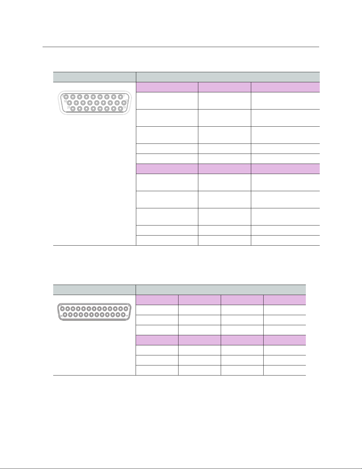
26 Pin Serial Data Connection
Component Description
Data 1 Data 3 Format Pin Orientation
(9) 232 In (6) 232 In, +422 In,
T-POV
User Guide
N/C for rs422
+485 I/O
Applicable to the T-POV 324
25 Pin Audio Connection
(18) 232 Out (15) 232 In, +422 In,
+485 I/O
(14) 232 In, +422 In,
+485 I/O
(4) -422 Out (20, 22, 24) Ground
(23) Data 3 Format (2) Format Bias (12v)
Data 2 Data 4 Tally
(8) 232 In, +422 In, +485
I/O
(17) -422 In, +485 I/O (13) -422 In, +485
(16) 232 Out, +422 Out (12) 232 Out, +422
(7) -422 Out (3) -422 Out
(23) Data 2 Format (21) Data 4 Format
(4) 232 In, +422 In,
+485 I/O
I/O
Out
Tie to Ground for rs232
Tie to Format Bias for
rs485
(11) GPI In
(1) GPI Out A
(10) Out B
Component Description
AUDIO 1 IN AUDIO 2 IN AUDIO 3 IN AUDIO 4 IN
(24) +Input (10) +Input (21) +Input (7) +Input
(12) -Input (23) -Input (9) -Input (20) -Input
(25) Ground (11) Ground (22) Ground (8) Ground
AUDIO 1 OUT AUDIO 2 OUT AUDIO 3 OUT AUDIO 4 OUT
(18) +Output (4) +Output (15) +Output (1) +Output
(6) -Output (17) -Output (3) -Output (14) -Output
(19) Ground (5) Ground (16) Ground (2) Ground
Applicable to T-POV 324
80
Page 87

Base Station 12VDC Terminal Block Wiring
Base Station 12VDC Terminal Block Wiring
Component Description
Pin 1: Minus Voltage Terminal
Pin 2: Plus Voltage Terminal
This cable is end-user supplied.
Serial Data Configuration
For the Serial Data connector on the T-POV 301, the Data 2 channel is configurable. To
select between RS4222 and RS485 serial communication, select the proper settings on a
dual dip-switch contained on the main circuit board inside the unit. The switch is directly
behind the right side of the serial connectors on both the base station and the camera unit.
To configure the Serial Data connector
1 Remove the top of the unit by removing the four screws as shown. A Mini-Mussel Shell
Camera Unit is shown as an example.
81
Fig. A-1: Removing the top of the Camera Unit
2 Flip the dual dip-switch contained on the main circuit board inside the RS422 or R485
unit. For a multi-unit Base Station, you must set each unit separately and units can be
set differently from each other.
• For RS422 serial communications, slide both switches to the back of the unit
(towards the serial connector).
Fig. A-2: Flip switches on an RS422
Page 88
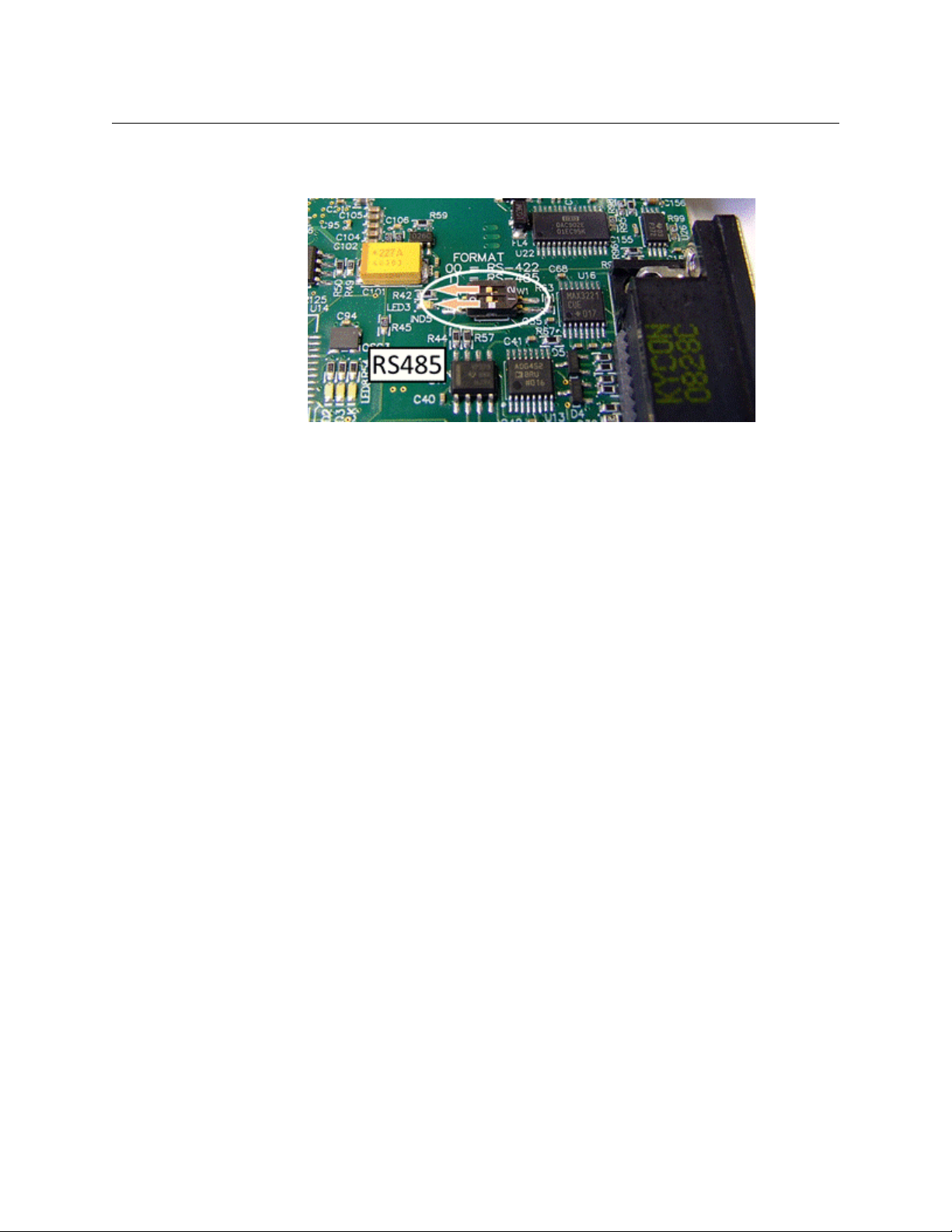
T-POV
User Guide
• For R485 serial communications, slide both switches to the front of the unit (away
from the serial connector).
Fig. A-3: Flip switches on an RS485
82
Page 89

Serial Data Configuration
83
 Loading...