

Page 1

Terrapin FTR-D6 User Guide
M4022-9900-102
24 July 2014
Page 2

Notices
Copyright & Trademark Notice
Copyright © 2014, Grass Valley. All rights reserved.
Belden, Belden Sending All The Right Signals, and the Belden logo are trademarks or
registered trademarks of Belden Inc. or its affiliated companies in the United States and
other jurisdictions. Grass Valley, are trademarks or registered trademarks of Grass Valley.
Belden Inc., Grass Valley, and other parties may also have trademark rights in other terms
used herein.
Terms and Conditions
Please read the following terms and conditions carefully. By using Terrapin FTR-D6
documentation, you agree to the following terms and conditions.
Grass Valley, a Belden Brand (“Grass Valley”) hereby grants permission and license to owners
of Terrapin FTR-D6 to use their product manuals for their own internal business use.
Manuals for Grass Valley products may not be reproduced or transmitted in any form or by
any means, electronic or mechanical, including photocopying and recording, for any
purpose unless specifically authorized in writing by Grass Valley.
A Grass Valley manual may have been revised to reflect changes made to the product
during its manufacturing life. Thus, different versions of a manual may exist for any given
product. Care should be taken to ensure that one obtains the proper manual version for a
specific product serial number.
Information in this document is subject to change without notice and does not represent a
commitment on the part of Grass Valley.
Warranty information is available in the Support section of the Grass Valley Web site
(www.miranda.com).
Title Terrapin FTR-D6 User Guide
Part Number M4022-9900-102
Revision 24 July 2014
ii
Page 3

Table of Contents
1 About Terrapin FTR-D6 . . . . . . . . . . . . . . . . . . . . . . . . . . . . . . . . . 1
About the Terrapin FTR-D6 System. . . . . . . . . . . . . . . . . . . . . . . . . . . . . . . . . . . . . . . . . . . . . . . . .2
Fiber Cable Overview . . . . . . . . . . . . . . . . . . . . . . . . . . . . . . . . . . . . . . . . . . . . . . . . . . . . . . . . . . 3
Block Diagram. . . . . . . . . . . . . . . . . . . . . . . . . . . . . . . . . . . . . . . . . . . . . . . . . . . . . . . . . . . . . . . . . 4
Optical Fiber Safety. . . . . . . . . . . . . . . . . . . . . . . . . . . . . . . . . . . . . . . . . . . . . . . . . . . . . . . . . . . . 4
About this User Guide . . . . . . . . . . . . . . . . . . . . . . . . . . . . . . . . . . . . . . . . . . . . . . . . . . . . . . . . . 4
Unpacking and the Terrapin FTR-D6 Fiber Transceiver . . . . . . . . . . . . . . . . . . . . . . . . . . . . . . 5
Product Returns . . . . . . . . . . . . . . . . . . . . . . . . . . . . . . . . . . . . . . . . . . . . . . . . . . . . . . . . . . . . . . . 5
Ordering Information. . . . . . . . . . . . . . . . . . . . . . . . . . . . . . . . . . . . . . . . . . . . . . . . . . . . . . . . . . 5
2 Components and Operator Modes . . . . . . . . . . . . . . . . . . . . . . 7
Terrapin FTR-D6 Components. . . . . . . . . . . . . . . . . . . . . . . . . . . . . . . . . . . . . . . . . . . . . . . . . . . . . . 8
Mode Select Switch Operation . . . . . . . . . . . . . . . . . . . . . . . . . . . . . . . . . . . . . . . . . . . . . . . . . 9
The Fiber and Power Labels. . . . . . . . . . . . . . . . . . . . . . . . . . . . . . . . . . . . . . . . . . . . . . . . . . . .9
Fiber Input Optical Power Meter . . . . . . . . . . . . . . . . . . . . . . . . . . . . . . . . . . . . . . . . . . . . . .10
The SDI BNC Connector labels . . . . . . . . . . . . . . . . . . . . . . . . . . . . . . . . . . . . . . . . . . . . . . . .11
The LED Mode Indicators . . . . . . . . . . . . . . . . . . . . . . . . . . . . . . . . . . . . . . . . . . . . . . . . . . . . .11
The Fiber I/O and Power panel . . . . . . . . . . . . . . . . . . . . . . . . . . . . . . . . . . . . . . . . . . . . . . . .12
The "Copper" BNC I/O Panel . . . . . . . . . . . . . . . . . . . . . . . . . . . . . . . . . . . . . . . . . . . . . . . . . .13
ADAP Power Supplies . . . . . . . . . . . . . . . . . . . . . . . . . . . . . . . . . . . . . . . . . . . . . . . . . . . . . . . .13
Operator Modes & LED Indicators . . . . . . . . . . . . . . . . . . . . . . . . . . . . . . . . . . . . . . . . . . . . . . . . .14
Terrapin FTR-D6 Input/Out Status Depends on Mode . . . . . . . . . . . . . . . . . . . . . . . . . .15
Mode 1 . . . . . . . . . . . . . . . . . . . . . . . . . . . . . . . . . . . . . . . . . . . . . . . . . . . . . . . . . . . . . . . . . . . . . . 15
Mode 2 . . . . . . . . . . . . . . . . . . . . . . . . . . . . . . . . . . . . . . . . . . . . . . . . . . . . . . . . . . . . . . . . . . . . . . 16
Mode 3 . . . . . . . . . . . . . . . . . . . . . . . . . . . . . . . . . . . . . . . . . . . . . . . . . . . . . . . . . . . . . . . . . . . . . . 16
Mode 4 . . . . . . . . . . . . . . . . . . . . . . . . . . . . . . . . . . . . . . . . . . . . . . . . . . . . . . . . . . . . . . . . . . . . . . 17
Supported Signal Types . . . . . . . . . . . . . . . . . . . . . . . . . . . . . . . . . . . . . . . . . . . . . . . . . . . . . . . . . .17
3 Terrapin FTR-D6 Transceiver Operation . . . . . . . . . . . . . . . . . 19
Best Practices . . . . . . . . . . . . . . . . . . . . . . . . . . . . . . . . . . . . . . . . . . . . . . . . . . . . . . . . . . . . . . . . . . . .20
Troubleshooting . . . . . . . . . . . . . . . . . . . . . . . . . . . . . . . . . . . . . . . . . . . . . . . . . . . . . . . . . . . . . . . . .21
Installing and Using the External Battery Operation. . . . . . . . . . . . . . . . . . . . . . . . . . . . . . . .22
4 Specifications . . . . . . . . . . . . . . . . . . . . . . . . . . . . . . . . . . . . . . . . . 25
iii
Page 4

Table of Contents
iv
Page 5

About Terrapin FTR-D6
This chapter provides an overview of the Terrapin FTR-D6 and includes the safety and
warranty information about it.
About the Terrapin FTR-D6 System . . . . . . . . . . . . . . . . . . . . . . . . . . . . . . . . . . . . . . . . . . . . . . . . . . . . . 2
Unpacking and the Terrapin FTR-D6 Fiber Transceiver . . . . . . . . . . . . . . . . . . . . . . . . . . . . . . . . . . 5
1
Page 6

About Terrapin FTR-D6
About the Terrapin FTR-D6 System
About the Terrapin FTR-D6 System
The Terrapin FTR-D6 provides the features of a fiber optic digital video transmitter, a fiber
optic digital video receiver, plus a six-output digital video distribution amplifier in a single
unit.
The transceiver handles a wide range of digital video rates. Supported formats include:
• 3 Gb/s HD/SDI: SMPTE 424M (reclocked)
• 1.5 Gb/s HD/SDI: SMPTE 292M (reclocked)
• 540 Mb/s: SMPTE 344M
• 270 Mb/s DVB/ASI (reclocked)
• 143 Mb/s: SMPTE 259M
• 19.4 Mb/s ATSC: SMPTE 310M
• AES and MADI Audio
• Non-standard digital signals to 3 Gb/s
The unit is interoperable with industry standard optical HD/SDI signals to/from other
equipment, such as Rattler™, Python™, TelePort™, Telethon™, and Viper™ series frames and
modules, as well as other manufacturers' routers, DAs, etc.
The Terrapin FTR-D6 accepts a 75 ohm coaxial input on a BNC connector or an optical signal
on an ST connector up to 3Gb/s, or both at the same time. The output of the unit can also
be applied to the six BNC connectors or an ST fiber connector, or both at the same time.
The Terrapin FTR-D6 operates in one of four modes. The mode is set by using a single pushbutton that allows the choice of the following:
• Fiber optic transmitter with six BNC outputs of the digital video signal
• Fiber optic repeater with six BNC outputs of the received digital video signal
• Fiber optic receiver with six BNC outputs and Fiber optic transmitter of a separate
digital video signal
• Fiber optic repeater and local digital video D.A.
Colored LEDs on the top of the Terrapin FTR-D6 unit show the current mode with easy-tounderstand arrows indicating signal flow of the copper and optical signals.
The Terrapin FTR-D6 can be used in "throw down" mode with an external AC power supply
or with the optional external battery mounted to the Terrapin FTR-D6 unit. Screw holes are
provided on the unit to allow the Terrapin FTR-D6 to be attached to any suitable surface.
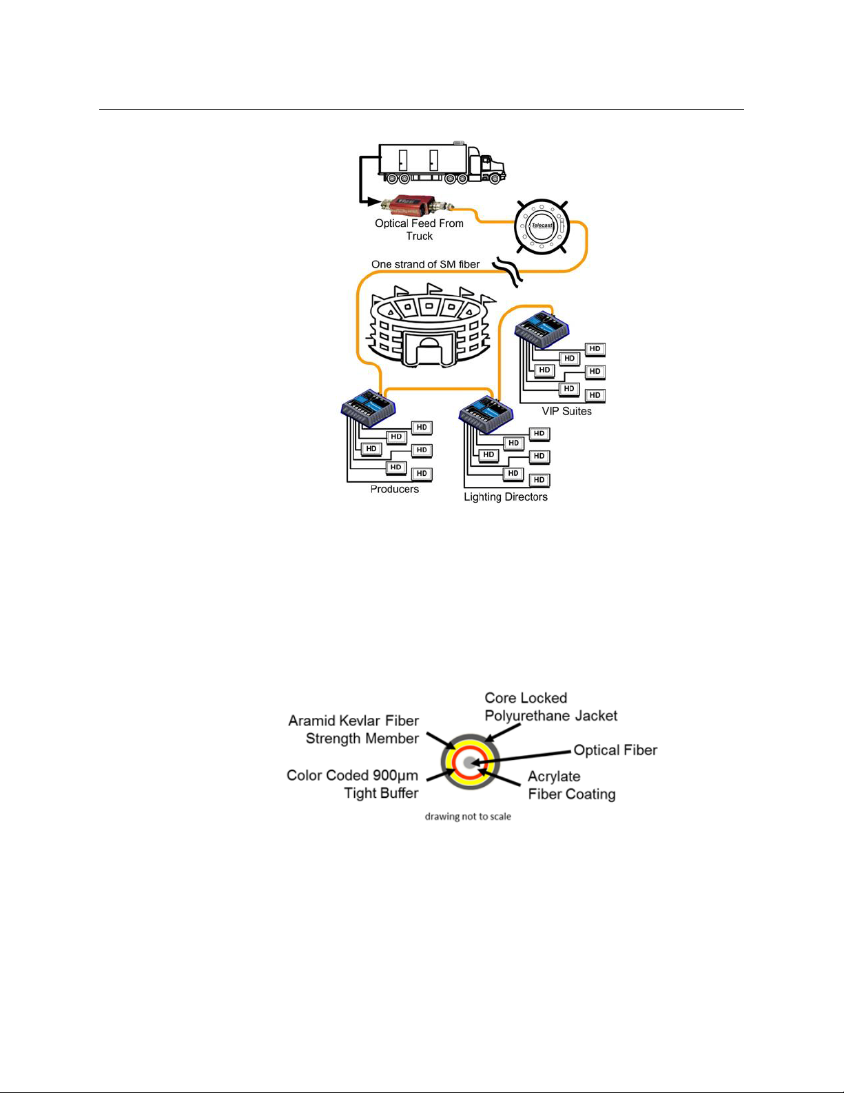
Figure 1-1 is a singlular example of a multitude of possible uses for the Terrapin FTR-D6.
This example shows a remote truck operating at a stadium where a series of Terrapin FTRD6 units are chained together by looping fiber feeds. Each Terrapin FTR-D6 is capable of
providing a BNC signal to six destinations.
2
Page 7
Terrapin FTR-D6
User Guide
Fiber Cable Overview
FiberOpticsandFiberOpticCablearethecoretechnologiesattheheartoftheTerrapin FTR-
D6 Fiber Transceiversystem.Theabilitytomultiplexandde‐multiplexavarietyofvideo,
audioanddatasignalssothattheycanbecarriedoverathinstrandofFiberOpticcablefor
longdistancesenables
isbeyondthescopeofthisdocument.
Fig. 1-1: Terrapin FTR-D6 Usage Example
theTerrapin FTR-D6.ThespecifictheoryandoperationofFiberOptics
Fig. 1-2: Single Mode Fiber Optic Cable Cross-Section (Illustrative Only)
3
Page 8
About Terrapin FTR-D6
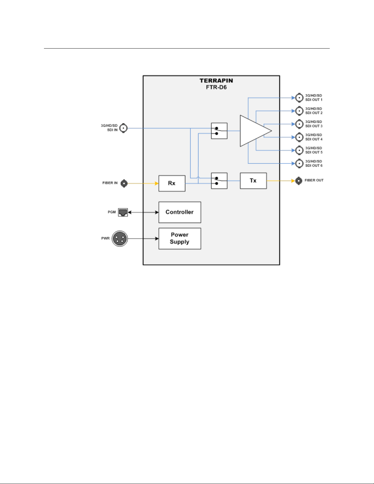
Block Diagram
Block Diagram
Optical Fiber Safety
Never look directly into the end of the optic fiber while either end of the system is
operating.
Always use cable connector caps when the cables are not connected. This protects the
connector from damage and the unlikely event of exposure to an operating optical link.
Keeping the caps in place when the connectors are not in use will prevent dirt and dust
from entering the connector and degrading the performance of the optical link.
About this User Guide
ThisTerrapin FTR-D6 Fiber Transceiverisdeliveredinasinglestandardmodel.Theone
optionistheadditionofanexternalbatterypowercapability.ThisUserGuidecovers
standardoperationaswellastheinstallationanduseoftheexternalbatteryoption.
Fig. 1-3: Terrapin FTR-D6 Block Diagram
4
Page 9

Unpacking and the Terrapin FTR-D6 Fiber Transceiver
Please consult your packing slip and purchase order to ensure that you have received all of
the expected components.
Inspect all components for scratches and other mechanical damage, and inspect the
electrical connectors for bent or damaged pins and latches. Report any missing or
damaged components to Grass Valley, a Belden Brand. (see Product Returns on page 5).
Leave the protective caps on the optical connectors whenever the fiber is disconnected.
Product Returns
In the unlikely event of damage to your Terrapin FTR-D6 Fiber Transceiver during shipping
or delivery,take note the damage with the delivery or shipping service. If any component
does not work correctly out of the box, contact Grass Valley Support (see Contact Us on
page 27).
Iftheproblemcannotberemediedthroughaservicetelephonecall,youwillreceivean
RMAnumber(ReturnofMerchandiseAuthorization).PleasenotethisRMAnumberinside
andoutsideofallshippingboxesandonalldocumentationprovidedwiththeitemstobe
returned.
Terrapin FTR-D6
User Guide
Ordering Information
Part Number Description
FTR-D6 Terrapin FTR-D6 Fiber Optic Transceiver
ADAP-AC-04 120VAC to 12VDC Power adaptor with circular locking connector
TRPN-AB-PLATE Battery mounting plate option for Anton-Bauer type Battery
TRPN-V-PLATE Battery mounting plate option for V-Mount type Battery
(US). Please contact Grass Valley for information regarding other
regions.
5
Page 10

About Terrapin FTR-D6
Ordering Information
6
Page 11

Components and Operator Modes
This chapter lists the components and operator modes for the Terrapin FTR-D6.
Terrapin FTR-D6 Components . . . . . . . . . . . . . . . . . . . . . . . . . . . . . . . . . . . . . . . . . . . . . . . . . . . . . . . . . 8
Operator Modes & LED Indicators . . . . . . . . . . . . . . . . . . . . . . . . . . . . . . . . . . . . . . . . . . . . . . . . . . . . . 14
Supported Signal Types . . . . . . . . . . . . . . . . . . . . . . . . . . . . . . . . . . . . . . . . . . . . . . . . . . . . . . . . . . . . . . 17
7
Page 12

Components and Operator Modes
Terrapin FTR-D6 Components
Terrapin FTR-D6 Components
The Terrapin FTR-D6 has three areas features:
• The top panel - see Figure 2-1
• The Fiber I/O and Power panel - see The Fiber I/O and Power panel on page 12
• The "Copper" BNC I/O panel - see The "Copper" BNC I/O Panel on page 13
Fig. 2-1: Terrapin FTR-D6 Fiber Transceiver Top Panel
The Terrapin FTR-D6 Fiber Transceiver Top Panel has five areas of interest:
• A - Mode Select Switch - see Mode Select Switch Operation on page 9
• B - The Fiber and Power labels - the fiber and power panel is not labeled, so use these
labels as your guide to the connectors - see The Fiber and Power Labels on page 9
• C - Fiber Input Optical Power Meter - see Fiber Input Optical Power Meter on page 10
• D - The SDI BNC Connector labels - the BNC connnector panel is unlabeled. Use these
labels as your guide to the connectors - see The SDI BNC Connector labels on page 11
• E - The LED mode indicators - see The LED Mode Indicators on page 11
8
Page 13

Mode Select Switch Operation
The mode select switch allows the selection of one of the four operating modes available
with the Terrapin FTR-D6.
To select a mode
1 Hold the Mode Select switch down for four seconds.
2 Observe the flashing LED indicators to determine the current operating mode and if
you want to change the mode, push the switch once. The Terrapin FTR-D6 will advance
to the next mode.
Keep pushing the switch until you reach the desired mode. As you cycle through the
modes the LEDs will change to indicate the active signal path.
3 When the desired mode is reached, release the switch and after four seconds, the
Terrapin FTR-D6 is programmed with the selected mode.
Terrapin FTR-D6
User Guide
Fig. 2-2: Mode Select switch
Note: If you pass by the desired mode, you must cycle through the
various modes until you get to the one you want. The Terrapin FTR-D6
will retain the last set mode when powered off.
For more information on the four modes please see Operator Modes &
LED Indicators on page 14.
The Fiber and Power Labels
The Fiber and Power Labels serve two functions. These are the labels for the connectors
directly below the labels on the end panel of the Terrapin FTR-D6. The In and Out labels also
serve as indicators/end points for the LED signal path indicators.
• The LED function is described in The LED Mode Indicators on page 11.
• The physical connectors are described in The Fiber I/O and Power panel on page 12.
Fig. 2-3: Fiber and Power Labels
9
Page 14

Components and Operator Modes
Fiber Input Optical Power Meter
Fiber Input Optical Power Meter
The Fiber Input Optical Power Meter serves two functions.
• The dBm scale indicates the relative strength of any Fiber Optic signal connected to the
Terrapin FTR-D6 unit. The meter covers a range of 0 dBM to -20dBm in 5 dBm
increments. The strongest signal is 0 dBm. The Terrapin FTR-D6 is designed to work
down to a signal strength of -20 dBm.
If these indicators fluctuate during operation, the system will continue to work.
However, if the signal strengthfalls below -20dBm, the Terrapin FTR-D6 may not
continue to pass the Fiber Optic signal.
• The Coax In indicator is a simple On/Off indication that an SDI signal has been
connected to the BNC Input of the Terrapin FTR-D6.
Fig. 2-4: Fiber Input Optical Power Meter
10
Page 15

The SDI BNC Connector labels
The SDI BNC Power Labels serve two functions. These are the labels for the connectors
directly below the labels on the BNC end panel of the Terrapin FTR-D6. The In and Out
labels also serve as indicators/end points for the LED signal path indicators.
The physical connectors are described on The Fiber I/O and Power panel on page 12.
The LED Mode Indicators
The Terrapin FTR-D6 uses a two-color LED system to indicate the various operating modes
of the system. The Fiber input and output and the SDI input each have an endpoint LED
indicator. The six SDI outputs have a single indicator for all six connections.
The operation of the LED indicators is described beginning on The LED Mode Indicators on
page 11.
Terrapin FTR-D6
User Guide
Fig. 2-5: SDI BNC Power Labels
Fig. 2-6: LED Mode Indicators
11
Page 16

Components and Operator Modes
The Fiber I/O and Power panel
The Fiber I/O and Power panel
The Terrapin FTR-D6 Fiber I/O and Power panel has four connectors. Each function
corresponds to the label indicated on the top panel of the unit.
1 The Power Connector is a 4-pin XLR type connector that takes a nominal 12V power
supply. The supplied power supply is the ADAP-AC-04-X, with X being the specific
geographic region covered (see Ordering Information on page 5).
The unit can also be powered by the optional External Battery option, which allows the
use of an Anton-Bauer or "V-Mount" type battery (see Installing and Using the External
Battery Operation on page 22).
2 The Terrapin FTR-D6 is equipped with an RJ45 data connector, which allows for future
firmware changes or upgrades. Currently, this connector has only a maintenance
function.
3 Fiber Optic ST Connector for Single Mode Fiber signal input.
4 Fiber Optic ST Connector for Single Mode Fiber signal output for transmitting the
connected BNC input, or for re-transmitting the Fiber Optic signal received on the Fiber
signal input (connector #3).
Fig. 2-7: Fiber I/O and Power Panel
12
For a list of all supported signal types, see Supported Signal Types on page 17.
Page 17

The "Copper" BNC I/O Panel
The Terrapin FTR-D6 BNC I/O end panel has seven connectors. Each function corresponds
to the label indicated on the top panel of the unit.
1 Input BNC connector: the Terrapin FTR-D6 accepts any digital signal from 19.2 Mb/s to
3 Gb/s, including many non-standard signals. Please see Supported Signal Types on
page 17 for a list of supported signal types.
2 Output BNC connectors: each output delivers an identical copy of the input signal
whether from the BNC Input (connector #1) or from the Fiber Optic input connection depending on the operating mode. Standard 270Mb/s, 1.5Gb/s & 3Gb/s signals are
reclocked.
Terrapin FTR-D6
User Guide
Fig. 2-8: BNC I/O Panel
ADAP Power Supplies
The Terrapin FTR-D6 Fiber Transceiver requires a power supply providing 5-16 volts at 1.5
Amps. The power supply shipped with the unit is the ADAP-AC-04-X (X being the specific
geography required). Any power supply meeting the required specification and providing
power through an XLR-4 Female connector can be used.
Part Number ADAP-AC-04: supplied with 4PIN XLR/A4F connector for the power plug on
the Terrapin FTR-D6 unit
Fig. 2-9: Power Supply
13
Page 18

Components and Operator Modes
Operator Modes & LED Indicators
Operator Modes & LED Indicators
The Terrapin FTR-D6 has four operating modes as follows:
• Fiber optic transmitter with six BNC outputs of the digital video signal
The digital signal input to the BNC is distributed from the six digital signal (BNC)
outputs and is transmitted from the Fiber Optic output.
• Fiber optic repeater with six BNC outputs of the received digital video signal
The Fiber Optic input is re-transmitted out of the Fiber Optic output and is also
distributed from the six digital signal (BNC) outputs.
• Fiber optic receiver with six BNC outputs and Fiber optic transmitter of a separate
digital video signal
The Fiber Optic input is distributed from the six digital signal (BNC) outputs, while a
separate BNC input is sent to the Fiber optic output.
• Fiber optic repeater and local digital video distribution
The Fiber Optic signal is re-transmitted and boosted out of the Fiber Optic Output,
while an input to the Digital signal BNC is distributed to the 6 digital signal outputs.
When the Terrapin FTR-D6 is set in a particular mode, LED indicators on the top panel
display the signal type and direction.
• Blue: Digital signals input to the BNC connector
• Orange: Fiber Optic sourced signals
Fig. 2-10: Signal legend
14
Page 19

Terrapin FTR-D6 Input/Out Status Depends on Mode
Please see the diagrams following for a visual explanation of each Terrapin FTR-D6
operating mode.
Operating Mode Fiber Optic Input Fiber Optic Output BNC Input BNC Output
Mode 1 Inactive Signal 1 Signal 1 Signal 1
Mode 2 Signal 1 Signal 1 Inactive Signal 1
Mode 3 Signal 1 Signal 2 Signal 2 Signal 1
Mode 4 Signal 1 Signal 1 Signal 2 Signal 2
Mode 1
The Fiber Optic Transmitter has six BNC outputs of the Digital Video Signal.
Terrapin FTR-D6
User Guide
Fig. 2-11: Terrapin FTR-D6 Mode 1 diagram
15
Page 20

Components and Operator Modes
Terrapin FTR-D6 Input/Out Status Depends on Mode
Mode 2
The Fiber Optic Repeater uses six BNC Outputs of the Received Digital Video Signal.
Fig. 2-12: Terrapin FTR-D6 Mode 2 diagram
Mode 3
Fiber Optic Receiver uses six BNC Outputs and a Fiber Optic Transmitter of a separate Digital
Video Signal.
16
Fig. 2-13: Terrapin FTR-D6 Mode 3 diagram
Page 21

Mode 4
Fiber Optic Repeater & Local Digital Video DA.
Terrapin FTR-D6
User Guide
Supported Signal Types
The Terrapin FTR-D6 supports the following signal types as of May 15, 2012.
Description Used For Standard
3 Gb/s SMPTE 424M HD/SDI HD/SDI Video SMPTE 424M HD/SDI
1.5 Gbps SMPTE 292M HD/SDI HD/SDI Video SMPTE 292M HD/SDI
19.4 Mbps SMPTE 310M Digital Video SMPTE 310M
143 to 540 Mbps SMPTE 259M/344M Digital Video SMPTE 259M/344M
DVB/ASI 270Mb/s Digital Video DVB/ASI 270Mbps
AES and MADI Audio Digital Audio AES and MADI
Non-standard digital signals to 3 Gb/s Other User must determine if signal
Fig. 2-14: Terrapin FTR-D6 Mode 4 diagram
quality is sufficient.
17
Page 22

Components and Operator Modes
Supported Signal Types
18
Page 23

Terrapin FTR-D6 Transceiver Operation
ThischapterdescribestheoperationoftheTerrapinFTR‐D6.Pleasekeepinmindthat
oncethesystemisproperlysetupandconfigured,thereisverylittletododuringnormal
operation.
Best Practices . . . . . . . . . . . . . . . . . . . . . . . . . . . . . . . . . . . . . . . . . . . . . . . . . . . . . . . . . . . . . . . . . . . . . . . . 20
Troubleshooting . . . . . . . . . . . . . . . . . . . . . . . . . . . . . . . . . . . . . . . . . . . . . . . . . . . . . . . . . . . . . . . . . . . . . 21
Installing and Using the External Battery Operation . . . . . . . . . . . . . . . . . . . . . . . . . . . . . . . . . . . 22
19
Page 24

Terrapin FTR-D6 Transceiver Operation
Best Practices
Best Practices
• Take care when using the laser equipment to prevent eye damage
• Protect the Fiber Optic Cable and the Fiber Optic Connectors. Always keep these
capped unless there are being connected.
• Make sure that the
Mounting the unit to a wall, the floor, or a piece of plywood using the mounting holes
on the unit can ensure safe and continuous operation.
TerrapinFTR‐D6 unit is secure and cannot be inadvertently moved.
Fig. 3-1: Terrapin FTR-D6 Bottom Place with Mounting Holes
• Once the system is set up and running, carefullymonitor the Fiber Input Optical Power
displays on the
TerrapinFTR‐D6. The system is digital, so the Signal Strength must
meet or exceed the requirements. When thesignal is no longer strong enough, the
signal stops.
• Be as careful during System tear down as during System setup.
•Read the Using Fiber Optics Guide for information on how to manage and deploy your
fiber optics cabling, safety precautions, tips & tricks, and recommendations for creating
complex fiber optic networks. You can find a copy of this document on the Support
portal (see Contact Us on page 27).
20
Page 25

Troubleshooting
Troubleshooting any technical issues with the Terrapin FTR-D6 Fiber Transceiver System is
similar to any piece of television production gear with the obvious exception of the core
Fiber Optic technology.
Keep the following in mind:
• Check all your cables for any broken connections or bad connectors.
• Ensure that the Power Supply is working or fully charged (for external battery)? If there
is a power problem, check the fuses.
• Ensurethat the
you need.
TerrapinFTR‐D6 will indicate a fault by blinking LEDs in the Fiber Input Optical
•The
Power section of the top panel. The blinking will occur at one second intervals.
Faults indicated may be due to excessively high operating temperature or possibly frp,
the reclocking function not working correctly. The unit may continue to operate at an
excessively high temperature, but you should take action to lower the temperature. If
the reclocking is not working properly, it will adversely affect the output.
• If you cannot resolve the problem in the field, contact Grass Valley support (see Contact
Us on page 27).
Terrapin FTR-D6
User Guide
TerrapinFTR‐D6 unit is in the correct operating mode for the operation
21
Page 26

Terrapin FTR-D6 Transceiver Operation
Anton-Bauer battery
mounting plate
V-Mount battery
mounting plate
Installing and Using the External Battery Operation
Installing and Using the External Battery Operation
The TerrapinFTR‐D6 can be operated using the optional external battery adaptor plate and
battery mount (see Product Returns on page 5 for ordering information). Contact Grass
Valley Support (see Contact Us on page 27) or your Solutions dealer directly for more
information.
The external power option consists of a replacement bottom plate for the
TerrapinFTR‐D6
and one of two external battery mounting units. When ordering the external battery
option, select one of the following:
• Anton-Bauer battery mounting plate (
Part‐TRPN‐AB‐PLATE)
• V-Mount battery mounting plate (Part–TRPN‐V‐PLATE)
Use of the battery mounting plate requires a user-supplied battery.
22
Fig. 3-2: Anton-Bauer and V-Mount Battery Mounting Plate
Fig. 3-3: External Battery Plate Components
The external battery plate is a field installable option.
Page 27

Terrapin FTR-D6
End of Unit with Power Connection
User Guide
To install an external battery
1 Unscrew the existing blank bottom plate from the
TerrapinFTR‐D6 unit (1). Retain the
mounting screws for re-use in the next step.
2 Mount the Battery Mount (3) to the External Power bottom plate (2) making sure to
pass the connector through the intended aperture and to not pinch the connector
cable between the two pieces.
In most cases, this step will not be necessary as the battery mount will be shipped
already attached to the External Power bottom plate.
Fig. 3-4: Connecting the External Battery Mounting Plate
3 Connect the Battery Mount connector to the BATTERY IN connector (Figure 3-5):
Fig. 3-5: Connecting the External Battery Mounting Plate
4 Carefully position the now-connected bottom plate on to the Terrapin FTR-D6, being
5 Attach the bottom plate to the TerrapinFTR‐D6 unit using the retaining screws set
careful not to pinch the cable between the
aside in Step 1.
TerrapinFTR‐D6 and the bottom plate.
23
Page 28

Terrapin FTR-D6 Transceiver Operation
Installing and Using the External Battery Operation
The External Battery option is now ready for use. Attach a charged battery to the unit and
confirm that the
TerrapinFTR‐D6 can be operated in the following power modes:
The
TerrapinFTR‐D6 operates correctly.
• AC power connected to the XLR.
• External Battery attached to the unit.
• Both AC Power connected and an External Battery attached to the unit. In this mode,
the unit will take power from both sources. Consider this method a way of providing a
backup power source to the unit in critical situations.
• The Optical Power LEDs will blink Red if battery power is too low to adequately operate
the Terrapin FTR-D6.
24
Page 29

Specifications
Transmission
Operating Wavelength......................................................... 1310, or 1270-1610 (CWDM)
Coaxial video connectors in/out.......................................................................................BNC
Optical Connectors (2)..............................................................................................................ST
Optical Source Laser Diod. ..................................................................... (FP or CWDM DFB)
Optical detector. ..................................................................................................PIN-TIA Diode
Transmitter output............................................................................................... -7 to +3 dBm
Receiver sensitivity....................................................................................... -20 dBm @ 3Gb/s
Link Margin/Distance.............................................................................. 15-25 dB/20-50 km
Fiber type.................................................single-mode or multimode (distance limited.)
Video
Transmission method ...................................................................................................... Digital
Input level. ............................................................................................800 mV (peak to peak)
Input Impedance.. ......................................................................................................... 75 ohms
Coax Equalization.............................................................................@ 2.97 Gb/s 100 meters
Output Impedance. ..............................................................................................75 ohms (x6)
-4
Bit-Error Rate. ..................................................................................... 10
Jitter ( color bars) .....................................................................≤ 0.3 UI @ 3G, ≤.2 UI @ 1.5G
Rise/Fall Times. ................................. < 120 ps @ 1.5Gb/s & 3Gb/s, ≈600ps @ 270Mb/s
(-20 dBm @ 3Gb/s)
:
HDX
Power Req..................................................................110-120/220-240 VAC, 50 to 60Hz
Power Consumption................................................................ 250 watts max @120VAC
Safety Interlock .....................................................................................32VAC Pilot, 5VDC
Sense return Main Output (to PowerPlus): ...................................................... 320VDC
Mechanical/Environmental
Dimensions: (LxWxH) .................................................................................... 5.9" x 6.2" x 1.7"
Weight, ................................................................................................................................ 14.4 oz.
Input Voltage .................................................................................................................5-16 VDC
Power connector plug ............................................................................................... XLR-4 pin
Power Consumption (typ.)........................................................................................ 4.4 watts
Indicators........................................................................ Power, Signal, Link, Optical Power
Temperature Range ....................................................................Operating -25° C to +60°C
Humidity Range ....................................................................0 to 95%RH, non-condensing
Certifications ............................................................................. FCC Part 15, RoHS, LEED, CE
25
Page 30

Specifications
26
Page 31

Grass Valley Technical Support
For technical assistance, please contact the Grass Valley Technical Support center nearest
you:
Contact Us
Americas
Office hours: 9:00 a.m. – 9:00 p.m. (EST)
Telephone: 1-800-224-7882
Fax: +1 514 335 1614
E-mail: support@miranda.com
Europe, Middle East, Africa, UK
Office hours: 9:00 a.m. – 6:00 p.m. (GMT)
Telephone: +44 118 952 3444
Fax: +44 118 952 3401
E-mail: eurotech@miranda.com
France
Office hours: 9:00 a.m. – 5:00 p.m. (GMT+1)
Telephone: +33 1 55 86 87 88
Fax: +33 1 55 86 00 29
E-mail: eurotech@miranda.com
Corporate Head Office
Asia
Office hours: 9:00 a.m. – 6:00 p.m. (GMT+8)
Telephone: +852 2539 6987
Fax: +852 2539 0804
E-mail: asiatech@miranda.com
China
Office hours: 9:00 a.m. – 6:00 p.m. (GMT+8)
Telephone: +86 10 5873 1814
E-mail: asiatech@miranda.com
Malaysia
Telephone: +60 3 2247 1808
EMERGENCY After Hours (Global)
Toll Free: 1-800-224-7882 (US and Canada)
Telephone: +1 514 333 1772
Grass Valley
3499 Douglas-B.-Floreani
St-Laurent, Quebec H4S 2C6
Canada
Telephone: +1 514 333 1772
Fax: +1 514 333 9828
Web: www.miranda.com
 Loading...