

Page 1

TelePort 3G User Guide
M4039-9900-102
24 July 2014
Page 2

Notices
Copyright & Trademark Notice
Copyright © 2008–2014, Grass Valley. All rights reserved.
Belden, Belden Sending All The Right Signals, and the Belden logo are trademarks or
registered trademarks of Belden Inc. or its affiliated companies in the United States and
other jurisdictions. Grass Valley, TelePort 3G are trademarks or registered trademarks of
Grass Valley. Belden Inc., Grass Valley, and other parties may also have trademark rights in
other terms used herein.
Terms and Conditions
Please read the following terms and conditions carefully. By using TelePort 3G
documentation, you agree to the following terms and conditions.
Grass Valley, a Belden Brand (“Grass Valley”) hereby grants permission and license to owners
of TelePort 3G to use their product manuals for their own internal business use. Manuals for
Grass Valley products may not be reproduced or transmitted in any form or by any means,
electronic or mechanical, including photocopying and recording, for any purpose unless
specifically authorized in writing by Grass Valley.
A Grass Valley manual may have been revised to reflect changes made to the product
during its manufacturing life. Thus, different versions of a manual may exist for any given
product. Care should be taken to ensure that one obtains the proper manual version for a
specific product serial number.
Information in this document is subject to change without notice and does not represent a
commitment on the part of Grass Valley.
Warranty information is available in the Support section of the Grass Valley Web site
(www.miranda.com).
Title TelePort 3G User Guide
Part Number M4039-9900-102
Revision 24 July 2014
ii
Page 3

Table of Contents
1 About TelePort 3G . . . . . . . . . . . . . . . . . . . . . . . . . . . . . . . . . . . . . . 1
About the TelePort 3G System . . . . . . . . . . . . . . . . . . . . . . . . . . . . . . . . . . . . . . . . . . . . . . . . . . . . .2
Fiber Cable Overview . . . . . . . . . . . . . . . . . . . . . . . . . . . . . . . . . . . . . . . . . . . . . . . . . . . . . . . . . . 3
Safety and Fiber Optic Systems . . . . . . . . . . . . . . . . . . . . . . . . . . . . . . . . . . . . . . . . . . . . . . . . . . . .4
Unpacking the TelePort 3G . . . . . . . . . . . . . . . . . . . . . . . . . . . . . . . . . . . . . . . . . . . . . . . . . . . .4
Optical Fiber Safety. . . . . . . . . . . . . . . . . . . . . . . . . . . . . . . . . . . . . . . . . . . . . . . . . . . . . . . . . . . . 4
FCC Part A Manual Notice. . . . . . . . . . . . . . . . . . . . . . . . . . . . . . . . . . . . . . . . . . . . . . . . . . . . . . 4
Product Returns . . . . . . . . . . . . . . . . . . . . . . . . . . . . . . . . . . . . . . . . . . . . . . . . . . . . . . . . . . . . . . . . . . . 5
2 Hardware and Block Diagrams . . . . . . . . . . . . . . . . . . . . . . . . . . 7
Available Models . . . . . . . . . . . . . . . . . . . . . . . . . . . . . . . . . . . . . . . . . . . . . . . . . . . . . . . . . . . . . . . . . .8
Block Diagrams. . . . . . . . . . . . . . . . . . . . . . . . . . . . . . . . . . . . . . . . . . . . . . . . . . . . . . . . . . . . . . . . . . .10
3 TelePort 3G Components . . . . . . . . . . . . . . . . . . . . . . . . . . . . . . 13
TelePort 3G Front Panel Features. . . . . . . . . . . . . . . . . . . . . . . . . . . . . . . . . . . . . . . . . . . . . . . . . .14
Power and Display Panel . . . . . . . . . . . . . . . . . . . . . . . . . . . . . . . . . . . . . . . . . . . . . . . . . . . . .14
TelePort 3G Transmitter . . . . . . . . . . . . . . . . . . . . . . . . . . . . . . . . . . . . . . . . . . . . . . . . . . . . . .14
Area A – SDI/DATA IN . . . . . . . . . . . . . . . . . . . . . . . . . . . . . . . . . . . . . . . . . . . . . . . . . . . . . . . . 15
TelePort 3G Receiver . . . . . . . . . . . . . . . . . . . . . . . . . . . . . . . . . . . . . . . . . . . . . . . . . . . . . . . . .15
Area A – SDI/DATA OUT . . . . . . . . . . . . . . . . . . . . . . . . . . . . . . . . . . . . . . . . . . . . . . . . . . . . . .15
TelePort 3G Transceiver. . . . . . . . . . . . . . . . . . . . . . . . . . . . . . . . . . . . . . . . . . . . . . . . . . . . . . .16
Area A – SDI/DATA IN . . . . . . . . . . . . . . . . . . . . . . . . . . . . . . . . . . . . . . . . . . . . . . . . . . . . . . . . 16
Area B – SDI/DATA OUT . . . . . . . . . . . . . . . . . . . . . . . . . . . . . . . . . . . . . . . . . . . . . . . . . . . . . .16
TelePort 3G Rear Panel Features. . . . . . . . . . . . . . . . . . . . . . . . . . . . . . . . . . . . . . . . . . . . . . . . . . .17
Area A - Rear Panel Power Connectors . . . . . . . . . . . . . . . . . . . . . . . . . . . . . . . . . . . . . . . .17
Redundant Power Supply Usage . . . . . . . . . . . . . . . . . . . . . . . . . . . . . . . . . . . . . . . . . . . . . 17
Area B – CAN BUS Connector . . . . . . . . . . . . . . . . . . . . . . . . . . . . . . . . . . . . . . . . . . . . . . . . .18
Area C – The ST Fiber Connectors . . . . . . . . . . . . . . . . . . . . . . . . . . . . . . . . . . . . . . . . . . . . .18
Power Connector Wiring. . . . . . . . . . . . . . . . . . . . . . . . . . . . . . . . . . . . . . . . . . . . . . . . . . . . . .18
Fiber ADAP Power Supplies . . . . . . . . . . . . . . . . . . . . . . . . . . . . . . . . . . . . . . . . . . . . . . . . . . . . . . .19
4 TelePort 3G Operation . . . . . . . . . . . . . . . . . . . . . . . . . . . . . . . . . 21
Fiber Optical Channel Monitoring . . . . . . . . . . . . . . . . . . . . . . . . . . . . . . . . . . . . . . . . . . . . . . . . .22
Using the TelePort 3G Optical Measurement Display. . . . . . . . . . . . . . . . . . . . . . . . . . . . . . .23
TelePort 3G Optical Measurement Display. . . . . . . . . . . . . . . . . . . . . . . . . . . . . . . . . . . . .23
System Firmware Display . . . . . . . . . . . . . . . . . . . . . . . . . . . . . . . . . . . . . . . . . . . . . . . . . . . . .24
Technical Information Display . . . . . . . . . . . . . . . . . . . . . . . . . . . . . . . . . . . . . . . . . . . . . . . .24
Best Practices . . . . . . . . . . . . . . . . . . . . . . . . . . . . . . . . . . . . . . . . . . . . . . . . . . . . . . . . . . . . . . . . . . . .25
Troubleshooting . . . . . . . . . . . . . . . . . . . . . . . . . . . . . . . . . . . . . . . . . . . . . . . . . . . . . . . . . . . . . . . . .25
iii
Page 4

Table of Contents
5 TelePort 3G Models and Part Numbers . . . . . . . . . . . . . . . . . . 27
Part Numbers . . . . . . . . . . . . . . . . . . . . . . . . . . . . . . . . . . . . . . . . . . . . . . . . . . . . . . . . . . . . . . . . . . . .28
Part Number Card Options. . . . . . . . . . . . . . . . . . . . . . . . . . . . . . . . . . . . . . . . . . . . . . . . . . . .28
Fiber I/O Cards . . . . . . . . . . . . . . . . . . . . . . . . . . . . . . . . . . . . . . . . . . . . . . . . . . . . . . . . . . . . . . .28
Example TelePort 3G Models. . . . . . . . . . . . . . . . . . . . . . . . . . . . . . . . . . . . . . . . . . . . . . . . . . . . . .29
Model TP3-MNPP-W8W8 . . . . . . . . . . . . . . . . . . . . . . . . . . . . . . . . . . . . . . . . . . . . . . . . . . . . .29
Model TP3-MNQU-W16 . . . . . . . . . . . . . . . . . . . . . . . . . . . . . . . . . . . . . . . . . . . . . . . . . . . . . . .29
Model TP3-PPPP-W16 . . . . . . . . . . . . . . . . . . . . . . . . . . . . . . . . . . . . . . . . . . . . . . . . . . . . . . . .29
6 Specifications . . . . . . . . . . . . . . . . . . . . . . . . . . . . . . . . . . . . . . . . . 31
iv
Page 5

About TelePort 3G
This chapter provides an overview of the TelePort 3G and includes the safety and warranty
information about it.
About the TelePort 3G System . . . . . . . . . . . . . . . . . . . . . . . . . . . . . . . . . . . . . . . . . . . . . . . . . . . . . . . . . 2
Safety and Fiber Optic Systems . . . . . . . . . . . . . . . . . . . . . . . . . . . . . . . . . . . . . . . . . . . . . . . . . . . . . . . . 4
Product Returns . . . . . . . . . . . . . . . . . . . . . . . . . . . . . . . . . . . . . . . . . . . . . . . . . . . . . . . . . . . . . . . . . . . . . . . 5
1
Page 6
About TelePort 3G
About the TelePort 3G System
About the TelePort 3G System
The TelePort is a CWDM multiplexer. It takes in optical signals within the 1200nm to
1670nm optical window, receives those signals, does an optical to electrical conversion retransmits them (electrical to optical) onto the proper wavelengths and then multiplexes
them using a CWDM optical multiplexer onto one fiber. This results in up to 16 signals per
fiber.
The TelePort is available in three versions:
• Version 1: supports 16 channels of transmission over a single fiber and pairs with a 16
channel receiver at the other end of the fiber link.
• Version 2: transmits eight channels and receives eight channels over two fibers (one
fiber for each direction) and pairs with an identical model at the other end.
• Version 3: sends eight signals and receives eight signals, but uses only one fiber and
requires different models for each end of the link.
In all models, singlemode fiber is required.
The optical signal that you supply to the TelePort must be digital and must be 3 Gb/sec or
less. There is no requirement that this optical signal originate from a Grass Valley product.
The TelePort 3G provides LEDs to indicate the presence of a Fiber optic signal at each front
panel ST Fiber Connector. The TelePort 3G features an integrated optical power meter for
monitoring received optical power and other system parameters.
The TelePort 3G also features dual 12-18 VDC power inputs for electrical redundancy.
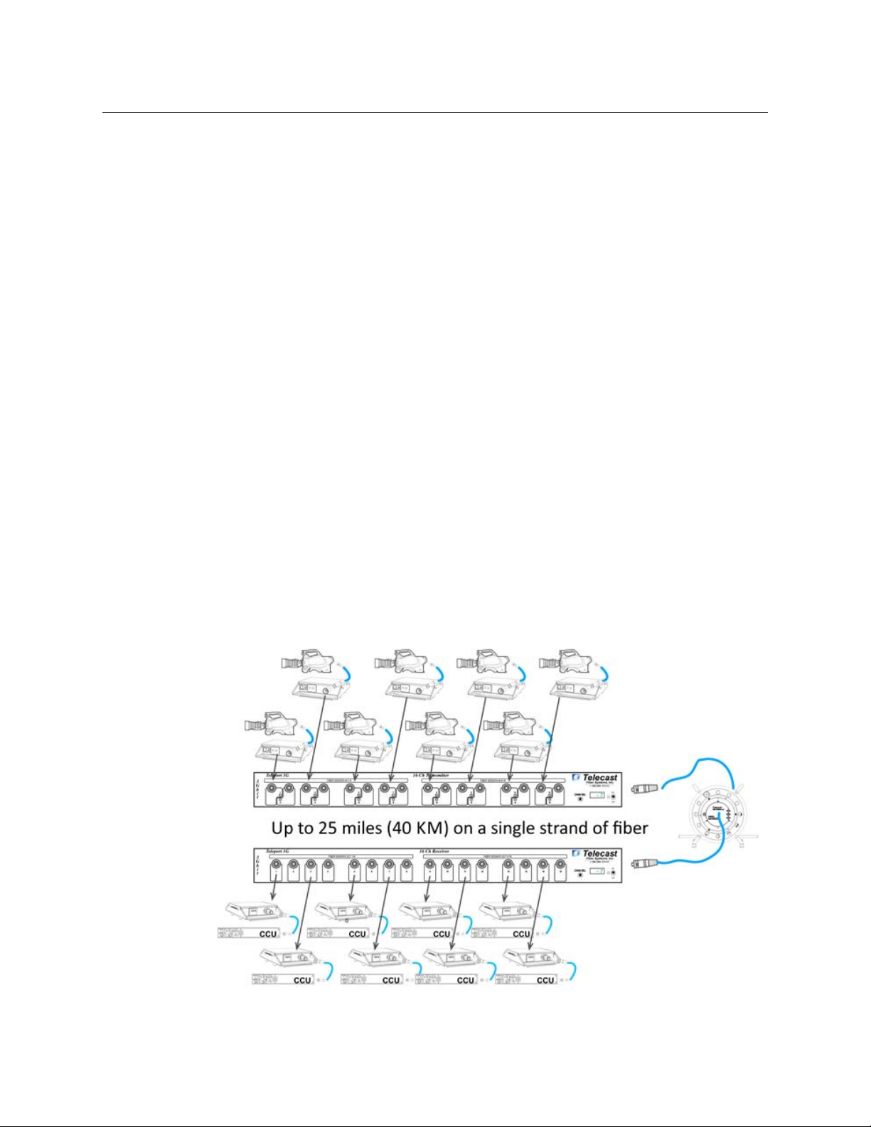
In Figure 1-1, a 16 Channel TelePort 3G Transmitter is connected to a 16 Channel TelePort
3G Receiver. Half of the total capacity connects to a remote set of production cameras to
the central control center. The open eight channels can be used for audio or data feeds, as
well as video monitoring feeds.
Fig. 1-1: Possible uses for the TelePort 3G
2
Page 7

Fiber Cable Overview
Fiber Optics and Fiber Optic Cable are the core technologies at the heart of the TelePort 3G
system. The ability to multiplex and de-multiplex multiple ranges of fiber optic signals
carrying SDI, Audio, and Data is what enables the TelePort 3G. The specific theory and
operation of Fiber Optics is beyond the scope of this document.
TelePort 3G
User Guide
Fig. 1-2: Single Mode Fiber Optic Cable Cross-Section
3
Page 8

About TelePort 3G
Safety and Fiber Optic Systems
Safety and Fiber Optic Systems
Unpacking the TelePort 3G
Please consult your packing slip and purchase order to ensure that you have received all of
the expected components.
Inspect all components for scratches and other mechanical damage, and inspect the
electrical connectors for bent or damaged pins and latches. Report any missing or
damaged components to Grass Valley (see Product Returns on page 5).
Leave the protective caps on the optical connectors whenever the fiber is disconnected.
Optical Fiber Safety
Never look directly into the end of the optic fiber while either end of the system is
operating.
This TelePort 3G contains CDRH Class 1 laser devices. To prevent damaging your eyes,
always avoid looking directly at, or staring into, the laser light located on an optical
connector or on the end of a fiber.
Infrared radiation is produced at the fiber connection port on the rear of the TX units and at
the end of any un-terminated optical fibers that are attached to this port. Avoid any direct
exposure to the light that comes from these sources.
Do not power up the unit when no fiber connector is attached to the fiber port.
There are no manual adjustments to be made inside the TelePort 3G. Do not attemptto
perform any type of service to this instrument other than any as instructed this User Guide.
Refer all servicing to Grass Valley, a Belden Brand.
Always use cable connector caps when the cables are not connected. This protects the
connector from damage and the unlikely event of exposure to an operating optical link.
Keeping the caps in place when the connectors are not in use will prevent dirt and dust
from entering the connector and degrading the performance of the optical link.
FCC Part A Manual Notice
This equipment has been tested and found to comply with the limits for a Class A digital
device, pursuant to part 15 of the FCC rules. These limits are designed to provide
reasonable protection against harmful interference when the equipment is operated in a
commercial environment.
This equipment generates, uses and can radiate radio frequency (RF) energy and, if not
installed and used in accordance with this User Guide, it may cause harmful interference to
radio communications.
4
Page 9

Product Returns
In the unlikely event of damage to your TelePort 3G during shipping or delivery please note
the damage with the delivery or shipping service and document the packaging and
product where you see damage. If any component does not work correctly out of the box
please contact Grass Valley support (see Contact Us on page 33).
If the problem cannot be remedied through a service telephone call,you will receive an
RMA number (Return of Merchandise Authorization). Please note this RMA number inside
and outside of all shipping boxes and on all documentation provided with the items to be
returned.
TelePort 3G
User Guide
5
Page 10

About TelePort 3G
Product Returns
6
Page 11

Hardware and Block Diagrams
This chapter lists the models available with the TelePort 3G and lists the block diagrams of
these models.
Available Models . . . . . . . . . . . . . . . . . . . . . . . . . . . . . . . . . . . . . . . . . . . . . . . . . . . . . . . . . . . . . . . . . . . . . . 8
Block Diagrams . . . . . . . . . . . . . . . . . . . . . . . . . . . . . . . . . . . . . . . . . . . . . . . . . . . . . . . . . . . . . . . . . . . . . . 10
7
Page 12
Hardware and Block Diagrams
Available Models
Available Models
The TelePort 3G is available in a variety of standard models. The following list covers the
models available at the time of publication.
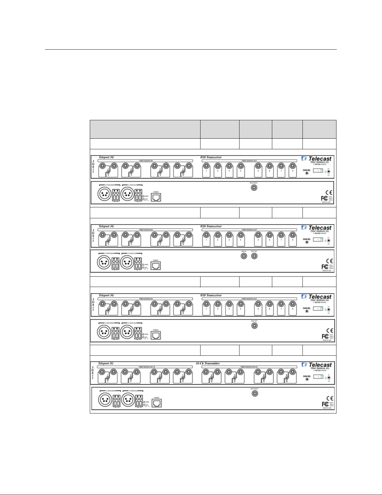
The TelePort 3G comes in five models. The three Transceiver types have identical front
panels and vary only on the rear panel depending on their Fiber Optic I/O configuration.
The Transmitter and Receiver types have their own unique models.
SDI/DATA
Part Number Typ e
TP3-MNPP-W16 Transceiver 8 8 1
TP3-MNPP-W8W8 Transceiver 8 8 2
TP3-QUPP-W16 Transceiver 8 8 1
Tra nsmit
SDI/DATA
Receive
Number of
Fibers
TP3-MNQU-W16 Transmitter 16 X 1
8
Page 13

TelePort 3G
User Guide
SDI/DATA
Part Number Typ e
TP3-PPPP-W16 Receiver X 16 1
Tra nsmit
SDI/DATA
Receive
Number of
Fibers
Typically the TelePort 3G systems are used in pairs as follows:
• The TP3-MNPP-W8W8 is used with another TP3-MNPP-W8W8
• The TP3-MNPP-W16 is used with a TP3-QUPP-W16
• The TP3-MNQU-W16 is used with a TP3-PPPP-W16
For diagrams of these systems,see see Block Diagrams on page 10.
However, it is possible to also use a TelePort 3G on one end and another devic e (such as a
Grass Valley CWDM) and various electrical-optical media, the Telecast-series Python or a
Telethon. Please consult with Grass Valley sales engineering or support for assistance with
such configurations (see Contact Us on page 33).
9
Page 14

Hardware and Block Diagrams
Block Diagrams
Block Diagrams
10
Fig. 2-1: 8x8 Channels TelePort 3G on 2 Fibers Block Diagram
Page 15

TelePort 3G
User Guide
Fig. 2-2: 8x8 Channels TelePort 3G on 1 Fiber Block Diagram
11
Page 16

Hardware and Block Diagrams
Block Diagrams
12
Fig. 2-3: 16 Channel TelePort 3G on 1 Fiber Block Diagram
Page 17

TelePort 3G Components
This chapter describes the main components of the TelePort 3G.
TelePort 3G Front Panel Features . . . . . . . . . . . . . . . . . . . . . . . . . . . . . . . . . . . . . . . . . . . . . . . . . . . . . . 14
TelePort 3G Rear Panel Features . . . . . . . . . . . . . . . . . . . . . . . . . . . . . . . . . . . . . . . . . . . . . . . . . . . . . . 17
Fiber ADAP Power Supplies . . . . . . . . . . . . . . . . . . . . . . . . . . . . . . . . . . . . . . . . . . . . . . . . . . . . . . . . . . . 19
13
Page 18

TelePort 3G Components
TelePort 3G Front Panel Features
TelePort 3G Front Panel Features
The TelePort 3G is used as a set of two units. The inputs to one unit of the pair are received
by the second unit and appear as the corresponding outputs.
Unit One Inputs 1-8 and 9-16 are reflected on Unit Two as Outputs 1-8 and 9-16.
Transceivers work identically in either direction with Inputs 1-8 reflected as Outputs 1-8 on
the opposite unit.
There is no requirement that all connectors be active. For example, fiber Inputs 1 and 3 are
used, while Input 2 is skipped, the output on the opposite unit will be on Output 1 and 3.
The TelePort 3G provides no user accessible adjustments. The unit is a pass-through device
with selectable monitoring capability.
Power and Display Panel
The Power and Display Area has four features:
• CHAN SEL – scrolls the LED display through each of the Fiber Channels
• Digital Display – display optical power levels, unit firmware and operating temperature
• Power Monitor LED – indicates Power Status
• Red: standby (power applied to rear connectors but unit not switched on)
• Green: unit switched on
• On/Off Switch – controls power to the TelePort 3G unit
TelePort 3G Transmitter
The TelePort 3G Transmitter Front Panel has two features:
• A - SDI/Data In - see Area A – SDI/DATA IN on page 15
• B - Power & Display Area - see Power and Display Panel on page 14
Fig. 3-1: Power and Display features
Fig. 3-2: TelePort 3G Transmitter Front Panel
14
Page 19

Area A – SDI/DATA IN
The TelePort 3G Transmitter has 16 Fiber Channel SDI/DATA Input ST connectors on the
front panel. All inputs operate identically and are multiplexed for transmission on the fiber
output of the unit. The Fiber signals are demultiplexed in the receiving unit and appear on
the corresponding ST outputs.
The Fiber connections can carry a digital optical signal of not more than 3 Gb/s.
Each front panel Fiber input has an LED monitor that indicates the following:
• Green: fiber optic connection present with active SDI signal
• Red: no optical connection detected or the active optical signal has fallen to -22 dBm
TelePort 3G Receiver
TelePort 3G
User Guide
Fig. 3-3: SDI/DATA Input ports
Fig. 3-4: TelePort 3G Front Panel
The TelePort 3G Receiver Front Panel has two features:
• A - SDI/Data Out - see Area A – SDI/DATA IN on page 15
• B - Power & Display Area - see Power and Display Panel on page 14
Area A – SDI/DATA OUT
Fig. 3-5: 4 SDI/DATA Output ST Connectors
The TelePort 3G Receiver and Transceiver have 16 Fiber Channel SDI/DATA Output ST
connectors on the front panel. All Outputs operate identically and are demultiplexed from
the signals received from the sending unit.
• The Fiber connections can carry a digital optical signal of not more than 3Gb/s
• The Fiber outputs do not have associated LED indicators
15
Page 20

TelePort 3G Components
TelePort 3G Transceiver
TelePort 3G Transceiver
The TelePort 3G Transceiver Front Panel has three features:
• A - SDI/Data In - see Area A – SDI/DATA IN on page 15
• B - SDI/Data Out - see Area A – SDI/DATA OUT on page 15
• C - Power & Display Area - see Power and Display Panel on page 14
Area A – SDI/DATA IN
Fig. 3-6: TelePort 3G Transceiver Front Panel
Fig. 3-7: 4 SDI/DATA In BNC Connectors
The TelePort 3G Transceiver has eight Fiber Channel SDI/DATA Input ST connectors on the
front panel. All inputs operate identically and are multiplexed for transmission on the fiber
output of the unit. The Fiber signals are demultiplexed in the receiving unit and appear on
the corresponding ST outputs.
The Fiber connections can carry a digital optical signal of not more than 3 Gb/s.
Each front panel Fiber input has an LED monitor that indicates the following:
• Green: fiber optic connection present with active SDI signal
• Red: no optical connection is detected or the active optical signal is below -22 dBm
Area B – SDI/DATA OUT
Fig. 3-8: 4 SDI/DATA Output BNC Connectors
The TelePort 3G Transceiver has eight Fiber Channel SDI/DATA Output ST connectors on the
front panel. All Outputs operate identically and are demultiplexed from the signals received
from the sending unit.
• The Fiber connections can carry a digital optical signal of not more than 3 Gb/s
• The Fiber outputs do not have associated LED indicators
16
Page 21

TelePort 3G Rear Panel Features
The TelePort 3G illustration is repeated for ease of use of this guide. All TelePort 3G units
operate the same: the only difference is in whether the Fiber Optic ST connectors are inputs
or outputs.
Fig. 3-9: TelePort 3G Rear Panel
Area A - Rear Panel Power Connectors
The TelePort 3G provides for the use of redundant 12-18 Volts DC power supplies. A battery
backup option is not provided for the TelePort 3G unit.
Power can be supplied to the unit by either a 4 pin XLR connector from an external power
supply such as a ADAP-AC-04 or with direct wiring from a 12-18 Volt DC power supply
connected to the provided terminal block.
TelePort 3G
User Guide
The main power supply can be of one type (XLR or direct wire) while the Aux power supply
is of the other type.
Fig. 3-10: Rear Panel Power Connectors
• 1 & 2 – Connectors for the Main 12-18 VDC power supply (XLR and Direct wire
terminal block)
• 3 & 4 – Connectors for the Main 12-18 VDC power supply (XLR and Direct wire
terminal block)
• 5 – MAIN/AUX Indicator LEDs – the LED for each power supply will be Green if power is
being applied to the TelePort 3G. If both Main and Aux are connected to a power
source both LEDs will be Green. A lit LED is not an indication of which power source is
being used at the time: only that the power source is good.
Redundant Power Supply Usage
The TelePort 3G power supply contains circuitry to detect which of the power sources (Main
or Aux) is producing the highest voltage and then uses that source to power the unit. If the
power sources are about the same than the TelePort 3G uses power from both.
17
Page 22

TelePort 3G Components
Area B – CAN BUS Connector
Area B – CAN BUS Connector
The CAN BUS connector is inactive in this version of the TelePort 3G. It may be used for
system monitoring in the future.
CAN is(Communication Area Network) is a protocol designed to support the monitoring of
microcontrollers.
Area C – The ST Fiber Connectors
Fig. 3-11: CAN BUS connector
The MUX IN connector receives up to eight or 16 channels depending on whether the unit
is a Tranceiver or Receiver.
Conversely the Transceiver or Transmitter MUX OUT connector sends the up to eight or 16
channels to the opposite TelePort 3G.
Power Connector Wiring
Figure Pin Function
Fig. 3-12: MUX IN and OUT connectors
1Ground
2Unused
3Unused
4
+Power12VDC
This matching connector is from either an ADAP-AC
04 or a customer 12-18 VDC power supply
1 Minus Voltage Terminal
2 Plus Voltage Terminal
18
Page 23

Fiber ADAP Power Supplies
The TelePort 3G requires a power supply providing 12-18 volts at 1.5 Amps. The power
supply recommended for the unit is the ADAP-AC-04-X (X: the specific geography
required). You can use any power supply meeting the required specification and providing
power through an XLR-4 Female connector. Please contact Grass Valley (see Contact Us on
page 33) or your Grass Valley dealer for more information.
You can also use direct wire power connections from a customer provided power source
with the Terminal Block power connections on the back panel.
TelePort 3G
User Guide
Fig. 3-13: Power Supply
Supplied with 4PIN XLR/A4F connector for the power plug on the TelePort 3G unit ( ADAPAC-04).
19
Page 24

TelePort 3G Components
Fiber ADAP Power Supplies
20
Page 25

TelePort 3G Operation
This chapter describes the operation of the TelePort 3G. Please keep in mind that once the
system is properly set up and configured, there is very little to do during normal operation.
Fiber Optical Channel Monitoring . . . . . . . . . . . . . . . . . . . . . . . . . . . . . . . . . . . . . . . . . . . . . . . . . . . . 22
Using the TelePort 3G Optical Measurement Display . . . . . . . . . . . . . . . . . . . . . . . . . . . . . . . . . . 23
Best Practices . . . . . . . . . . . . . . . . . . . . . . . . . . . . . . . . . . . . . . . . . . . . . . . . . . . . . . . . . . . . . . . . . . . . . . . . 25
Troubleshooting . . . . . . . . . . . . . . . . . . . . . . . . . . . . . . . . . . . . . . . . . . . . . . . . . . . . . . . . . . . . . . . . . . . . . 25
21
Page 26

TelePort 3G Operation
Fiber Optical Channel Monitoring
Fiber Optical Channel Monitoring
The TelePort 3G provides direct digital readout of the Fiber Optic Link signal strength for
signals received at the unit. This readout is presented in units of dBm. It is useful to
understand both the dB or decibel and the dBm or decibel referenced to one milliwatt.
The decibel (dB) is a logarithmic unit of measurement that expresses the magnitude of a
physical quantity (usually power or intensity) relative to a specified or implied reference
level. Since it expresses a ratio of two quantities with the same unit, it is a dimensionless,
relative unit. A decibel is one tenth of a bel, a seldom-used unit. Typically dB has been
employed in Audio Measurement and Fiber Optics among many uses.
Proper measurement of signal strength requires an absolute measurement and the dBm
provides this measurement. Since it is referenced to the milliwatt, it is an absolute unit,
used when measuring absolute power. By comparison, the decibel (dB) is used for
quantifying the ratio between two values, such as signal-to-noise ratio.
The TelePort 3G operates within a defined range of Fiber Optic Link signal strength. The
minimum recommended signal strength is -20 dBm or better. Typically the system should
operate at levels between -8 dBm and -20 dBm. The standard laser output strength is
-6 dBm. Cable length affects signal strength as does the number of connections between
the two TelePort 3G units. Any use of repeaters of cable bulkhead connector will produce a
minimal signal loss through each connection.
The optical output from each transmitter is generated by an infrared laser diode that is
coupled to a CWDM and onto the fiber. User connections on the TelePort 3G are made at
the bulkhead ST type connectors on the front and rear panels. Operation is intended for
use on single mode fiber. Since the CWDM output of the Python is the aggregate output of
all 8 or 16 optical transmitters inside the frame, the total optical power output on a single
fiber optic cable will be in the +4 to +8 dBm range. Standard practice of NEVER looking
directly into a fiber should be followed at all times.
The maximum fiber distance is defined by the optical loss margin. The RX signal must be
- 20 dBm or better. Losses on single mode fiber are approximately 0.5 dB/km or less.
CWDM’s account for about 5 dBm of loss per pair and must be considered when computing
your link loss budget.
The integrated optical power meter will show the received optical power for each receiver
but note that this figure is post CWDM.
22
Page 27

Using the TelePort 3G Optical Measurement Display
Flicking the switch
left or right
The optical measurement functionality is similar across all three types of TelePort 3G. A
transceiver, transmitter and receiver work identically with one exception. The system
reports fiber optical strength only for fiber optic signals received at a unit. Transmission
strength is not measured.
TelePort 3G Optical Measurement Display
The TelePort 3G optical signal strength display has characteristics for the TelePort 3G
Transmitter, Receiver, and Transceiver.
The Channel Select switch is a dual function switch:
• Flicking to the right allows scrolling through the individual channels to provide basic
status on the signal.
• Flicking to the left provides additional information about the current channel.
TelePort 3G
User Guide
Fig. 4-1: Flicking the CHAN SEL switch
Scroll through the signal channels by flicking the switch to the right. The system reports on
the installed SDI channels and the installed fiber channels being transmitted by the unit.
In a 8 x8 Transceiver, the CHAN SEL switch will display the eight Transmit channels, first
followed by the eight Receive Channels.
After the last channel, the display will show the current ambient temperature within the
unit chassis in degrees Celsius.
After each flick, the display will indicate the monitored channel such as TPx01 or TPx02. For
each TX channel, you can flick the switch to the left to display Technical Information about
the channel. Receive Channels are not monitored in the TelePort 3G unit.
23
Page 28

TelePort 3G Operation
System Firmware Display
System Firmware Display
The TelePort 3G display will display the current firmware version when the unit is powered
on. This appears in the display as a scrolling series of alphanumeric character four
characters wide.
Technical Information Display
Flicking the CHAN SEL switch to the left provides additional technical information that
identifies the specific physical channel that is being measured. This information is
presented in scrolling format four characters wide.
Fig. 4-2: Firmware display
Fig. 4-3: Technical Information display
24
Page 29

Best Practices
• Takecarearound the laser equpiment to avoid the possibility of eye damage
• Protect the Fiber Optic Cable and the Fiber Optic Connectors. Always keep these
•Read the Using Fiber Optics Guide for information on how to manage and deploy your
• Make sure that the TelePort 3G unit is secure and cannot be inadvertently moved or
• Secure the power supplies and power connections toensure power is continuous.
• Once the system is set up and running, do not ignore the system display monitor on
• The system is digital,so the Signal Strength will either meet or exceed te requirements.
• Be as careful during System tear down as during System setup.
TelePort 3G
User Guide
capped unless there are being connected.
fiber optics cabling, safety precautions, tips & tricks, and recommendations for creating
complex fiber optic networks. You can find a copy of this document on the Support
portal (see Contact Us on page 33).
kicked about. The units may usually be rack-mounted and therefore safe and secure
but in instances where it must be used in “table top” operation ensure that the
connectors on both the front and rear panes cannot be damaged by being
inadvertently struck or pulled.
the TelePort 3G.
When it is no longer strong enough, the signal stops.
Troubleshooting
Troubleshooting any technical issues with the TelePort 3G System is similar to any piece of
television production gear with the obvious exception of the core Fiber Optic technology.
Here is a list of things to look out for:
• Check all your cables for any broken connections or bad connectors.
• Ensure that the Power Supply is working.
• If you cannot resolve the problem in the field,contact Grass Valley Support (see Contact
Us on page 33).
25
Page 30

TelePort 3G Operation
Troubleshooting
26
Page 31

TelePort 3G Models and Part Numbers
This chapter explains how to decode the TelePort 3G Part Number. Sample part numbers
are decoded at the end of this section.
Part Numbers . . . . . . . . . . . . . . . . . . . . . . . . . . . . . . . . . . . . . . . . . . . . . . . . . . . . . . . . . . . . . . . . . . . . . . . . 28
Example TelePort 3G Models . . . . . . . . . . . . . . . . . . . . . . . . . . . . . . . . . . . . . . . . . . . . . . . . . . . . . . . . . . 29
27
Page 32

TelePort 3G Models and Part Numbers
Part Numbers
Part Numbers
The TelePort 3G part number consists of three sections as described below:
• A - The product designation – in this case TP3 stands for TelePort 3G
• B - Channel Card Options – the four letters correspond to the four available slots. If a
position has “0” than the slot is empty. The available card options are listed below.
• C - Fiber I/O Options – the number indicates the number of fiber optic channels. The
I/O options are listed below.
Part Number Card Options
All cards have four channels.
Fig. 5-1: TelePort 3G part number
Code
Letter
Fiber I/O Cards
Desig. Usage Ty pe Wavelength
W8 Receive or Transmit 1 – Fiber I/0 – 8 channels CWDM
W18 Receive or Transmit 1 – Fiber I/0 – 16 channels CWDM
Usage Typ e Wavelen gth
M Transmit CWDM 1310 Low Range:
1271, 1291, 1311, 1331 nm
N Transmit CWDM 1310 High Range:
1351, 1371, 1411, 1431 nm
Q Transmit CWDM 1550 Low Range:
1471, 1491, 1511, 1531 nm
U Transmit CWDM 1550 High Range:
1551, 1571, 1591, 1611 nm
P Receive Demux Leads Only Straight Through Connectors
28
Page 33

TelePort 3G
Example TelePort 3G Models
Model TP3-MNPP-W8W8
Model TP3-MNPP-W8W8
Transceiver with eight Transmit Channels and eight Receive Channels with CWDM and 2 Fibers I/O
Position Item Description
Card Slot #1 M CWDM Multiplexer 1310 nm Low Range
Card Slot #2 N CWDM Multiplexer 1310 nm High Range
Card Slot #3 P Four Straight Through Connectors
Card Slot #4 P Four Straight Through Connectors
I/O #1 W8 8 Channel Fiber I/O Card
I/O #2 W8 8 Channel Fiber I/O Card
Model TP3-MNQU-W16
User Guide
Model TP3-MNQU-W16
Transmitter with 16 Channels equipped with CWDM and single Fiber I/O
Position Item Description
Card Slot #1 M CWDM Multiplexer 1310 nm Low Range
Card Slot #2 N CWDM Multiplexer 1310 nm High Range
Card Slot #3 Q CWDM Multiplexer 1550 nm Low Range
Card Slot #4 U CWDM Multiplexer 1550 nm High Range
I/O #1 W16
I/O #2 NA
16ChannelFiberI/OCard
Model TP3-PPPP-W16
Model TP3-PPPP-W16 – Receiver with 16 Channels equipped with CWDM and single Fiber I/O
Position Item Description
Card Slot #1 P Four Straight Through Connectors
Card Slot #2 P Four Straight Through Connectors
Card Slot #3 P Four Straight Through Connectors
Card Slot #4 P Four Straight Through Connectors
I/O #1 W16 16 Channel Fiber I/O Card
I/O #2 NA
29
Page 34

TelePort 3G Models and Part Numbers
Model TP3-PPPP-W16
30
Page 35

Specifications
Transmitter Inputs
Interface: ............................................................................................................... Digital optical
Input wavelength range: ............................................................................1250 to 1650 nm
Input optical power range: ............................................................................. -2 to -22 dBm
Input optical connector: .........................................................................................................ST
Maximum data rate, per channel: .............................................................................. 3 Gbps
Transmitter Output
Interface: ................................................................................................ Digital optical, CWDM
Output wavelengths:
1300 nm range standard: 1271, 1291, 1311, 1331, 1351, 1371, 1411 and 1431 nm
1500 nm range optional: 1471, 1491, 1511, 1531, 1551, 1571, 1591 and 1611 nm
Output power, per channel, typical: ......................................................-3 dBm (±3 dBm)
Receiver CWDM
Input wavelengths:
1300 nm range standard: 1271, 1291, 1311, 1331, 1351, 1371, 1411 and 1431 nm
1500 nm range optional: 1471, 1491, 1511, 1531, 1551, 1571, 1591 and 1611 nm
Mechanical/Environmental
Dimensions (LxWxH) .........................................................................................8"x17.5"x1.75"
Weight, each end...................................................................................................................5 lbs
Connectors: Optical ...................................................................................................................ST
Input voltage............................................................................................................... 12-18 VDC
Power consumption......................................................................................................... <25 W
Indicators................................................... Power ON, SDI Data Presence, Optical Power
Temperature Range ...............................................................................................-20° to 55 °C
Humidity Range ..........................................................................0 to 95 % non-condensing
Compliance
Laser Safety.............................................................................................................. Class 1 Laser
EMI/RFI....................................................................................Complies with IEC/EN 60825-1
Certifications ..........................................................................................................................RoHS
31
Page 36

Specifications
32
Page 37

Grass Valley Technical Support
For technical assistance, please contact the Grass Valley Technical Support center nearest
you:
Contact Us
Americas
Office hours: 9:00 a.m. – 9:00 p.m. (EST)
Telephone: 1-800-224-7882
Fax: +1 514 335 1614
E-mail: support@miranda.com
Europe, Middle East, Africa, UK
Office hours: 9:00 a.m. – 6:00 p.m. (GMT)
Telephone: +44 118 952 3444
Fax: +44 118 952 3401
E-mail: eurotech@miranda.com
France
Office hours: 9:00 a.m. – 5:00 p.m. (GMT+1)
Telephone: +33 1 55 86 87 88
Fax: +33 1 55 86 00 29
E-mail: eurotech@miranda.com
Corporate Head Office
Asia
Office hours: 9:00 a.m. – 6:00 p.m. (GMT+8)
Telephone: +852 2539 6987
Fax: +852 2539 0804
E-mail: asiatech@miranda.com
China
Office hours: 9:00 a.m. – 6:00 p.m. (GMT+8)
Telephone: +86 10 5873 1814
E-mail: asiatech@miranda.com
Malaysia
Telephone: +60 3 2247 1808
EMERGENCY After Hours (Global)
Toll Free: 1-800-224-7882 (US and Canada)
Telephone: +1 514 333 1772
Grass Valley
3499 Douglas-B.-Floreani
St-Laurent, Quebec H4S 2C6
Canada
Telephone: +1 514 333 1772
Fax: +1 514 333 9828
Web: www.miranda.com
 Loading...