

Page 1

T2 Elite 2/Pro 2/Express 2
T2 Elite/Pro/Express
INTELLIGENT DIGITAL DISK RECORDER
Service Manual
Version 2.3.0
www.grassvalley.com
F2811604051
May 2016
Page 2

Copyright
Copyright 2012 Grass Valley K.K. All rights reserved. Portions of software © 2000 – 2012, Microsoft
Corporation. All rights reserved. This document may not be copied in whole or in part, or otherwise
reproduced except as specifically permitted under U.S. copyright law, without the prior written
consent of Grass Valley, Inc., P.O. Box 59900, Nevada City, California 95959-7900. This product
may be covered by one or more U.S. and foreign patents.
Grass Valley is a trademark of GVBB Holdings S.a.r.l.
Disclaimer Product options and specifications subject to change without notice. The information in this
manual is furnished for informational use only, is subject to change without notice, and should
not be construed as a commitment by Grass Valley, Inc. Grass Valley, Inc. assumes no
responsibility or liability for any errors or inaccuracies that may appear in this publication.
U.S. Government
Restricted Rights
Legend
Trademarks and
Logos
Use, duplication, or disclosure by the United States Government is subject to restrictions as set
forth in subparagraph (c)(1)(ii) of the Rights in Technical Data and Computer Software clause
at DFARS 252.277-7013 or in subparagraph c(1) and (2) of the Commercial Computer
Software Restricted Rights clause at FAR 52.227-19, as applicable. Manufacturer is Grass
Valley, Inc., P.O. Box 59900, Nevada City, California 95959-7900 U.S.A.
Grass Valley is a trademark of GVBB Holdings S.a.r.l. Grass Valley USA, LLC products are covered
by U.S. and foreign patents, issued and pending. Additional information regarding Grass Valley
USA, LLC trademarks and other proprietary rights may be found at www.grassvalley.com.
Other trademarks and logos used in this document are either registered
trademarks or trademarks of the manufacturers or vendors of the associated
products, such as Microsoft
player, Internet Explorer® internet browser, and SQL Server™. QuickTime and
the QuickTime logo are trademarks or registered trademarks of Apple, Inc., used
under license therefrom. Intel, Core i7 are the trademarks or registered
trademarks of Intel Corporation or its subsidiaries in the United States of America and other
countries.
®
Windows® operating system, Windows Media
®
Grass Valley Web Site This public Web site contains all the latest manuals and documentation, and additional support
information. Use the following URL.
http://www.grassvalley.com.
Manual Explanation • If there are any variations between the explanation in this manual and the actual application
method, priority is given to the actual application method.
• This manual is a common manual for T2 Elite 2, T2 Pro 2, T2 Express 2, T2 Elite, T2 Pro and
T2 Express. Screenshots and illustrations in this manual may vary from those of the actual
product.
• The screenshots used as examples in this manual are those of the development stage, so
they may vary from those in the final product.
• This manual is written for users who have a basic knowledge of how to use a computer.
• If there are no special instructions, perform the same operation as a normal computer
operation.
• The contents of this product may modify without prior notice.
T2 Elite 2/Pro 2/Express 2/Elite/Pro/Express Service Manual
Version 2.3.0
Copyright © 2012 - 2016 Grass Valley. All rights reserved.
2 T2 Elite 2/Pro 2/Express 2/Elite/Pro/Express Service Manual May 16, 2016
Page 3

Contents
Safety Summaries.............................................................................................. 7
Finding Information........................................................................................... 11
Chapter 1 Product Description
Overview Description .............................................................................................. 14
System Description ................................................................................................. 15
PC Subsystem.................................................................................................... 16
Codec Subsystem .............................................................................................. 16
Front Subsystem ................................................................................................ 17
XLR board .......................................................................................................... 17
Fuse board ......................................................................................................... 17
T2 orientation .......................................................................................................... 18
FRU locations (T2 Elite/Pro/Express)................................................................. 18
FRU locations (T2 Elite 2/Pro 2/Express 2)........................................................ 19
FRU functional descriptions .................................................................................... 20
Touch screen LCD.............................................................................................. 20
JOG/Shuttle knob ............................................................................................... 20
Button kit............................................................................................................. 20
Front USB group unit.......................................................................................... 20
Recovery UFD (USB Flash Drive) ...................................................................... 20
Fan (Center/Rear) .............................................................................................. 20
Power supply unit ............................................................................................... 20
2.5 inch removable SSD bay .............................................................................. 21
SSD (for the system) .......................................................................................... 21
HDD/SSD (for data)............................................................................................ 21
I/O board unit...................................................................................................... 21
XLR×6 unit.......................................................................................................... 21
SATA card unit ................................................................................................... 21
Memory (RAM) ................................................................................................... 22
Fuse board unit................................................................................................... 22
Front USB 3.0 board........................................................................................... 22
USB 3.0 cable..................................................................................................... 22
PCI-e USB 3.0 card ............................................................................................ 22
Rear USB 3.0 port .............................................................................................. 22
Media Card Reader Assy ................................................................................... 22
Status indicators...................................................................................................... 23
Power LED ......................................................................................................... 23
LAN port indicator codes .................................................................................... 23
Chapter 2 Maintenance Procedures
Cleaning the touch screen LCD .............................................................................. 26
Starting and exiting the maintenance mode ............................................................ 26
Starting the maintenance mode.......................................................................... 27
Exiting the maintenance mode ........................................................................... 28
Using the Maintenance Tools .................................................................................. 30
Launching the Maintenance Tools...................................................................... 30
Closing the Maintenance Tools .......................................................................... 30
Media drive maintenance ................................................................................... 31
Data maintenance .............................................................................................. 34
System related maintenance .............................................................................. 40
Using the Windows desktop .................................................................................... 44
Verifying, building, and rebuilding a RAID volume .................................................. 44
Verifying the RAID volume ................................................................................. 44
Building the RAID volume................................................................................... 47
Rebuilding the RAID volume (for only the T2 Pro 2/Pro).................................... 54
Restoring to the factory default condition ................................................................ 59
May 16, 2016 T2 Elite 2/Pro 2/Express 2/Elite/Pro/Express Service Manual 3
Page 4

Contents
Recovery procedure for T2 Elite/Pro/Express .................................................... 59
Recovery procedure for T2 Elite 2/Pro 2/Express 2 ........................................... 66
T2 Recovery Utility for T2 Elite 2/Pro 2/Express 2 ............................................. 68
Chapter 3 Troubleshooting Problems
Step 1: Check configurations .................................................................................. 74
Step 2: Check connections and external equipment ............................................... 74
Shutdown/restart problems ..................................................................................... 74
Checking external equipment.................................................................................. 75
PC monitor problems.......................................................................................... 75
Keyboard problems ............................................................................................ 75
Mouse problems................................................................................................. 76
Motherboard/BIOS startup ...................................................................................... 76
Windows startup...................................................................................................... 78
T2 system startup.................................................................................................... 78
Thermal problems ................................................................................................... 78
I/O board unit problems........................................................................................... 79
Power supply problems........................................................................................... 80
Front panel problems .............................................................................................. 80
Touch screen LCD and control buttons problems .............................................. 80
Interconnect board problems.............................................................................. 81
2.5 inch removable SSD bay problems................................................................... 82
Media card reader problems ................................................................................... 83
Video problems ....................................................................................................... 83
Audio problems ....................................................................................................... 84
Timecode problems................................................................................................. 84
Operational problems.............................................................................................. 85
System problems .................................................................................................... 85
Storage problems.................................................................................................... 86
Media File System problems .............................................................................. 86
Media disk problems .......................................................................................... 86
Checking the storage system ............................................................................. 88
Chapter 4 Removing and Replacing FRUs
Precautions before operations ................................................................................ 90
Required tools .................................................................................................... 90
Turning off the system and disconnecting the power cord from T2.................... 90
Top cover (front) removal........................................................................................ 92
Top cover (rear) removal......................................................................................... 93
HDD/SSD (for data) removal................................................................................... 94
SSD (for the system) removal ................................................................................. 97
2.5 inch removable SSD bay removal..................................................................... 99
Front USB 3.0 board removal ................................................................................. 102
Media Card Reader Assy removal .......................................................................... 103
Fuse board unit removal ......................................................................................... 105
Front panel removal ................................................................................................ 107
Jog knob removal.................................................................................................... 109
Shuttle knob removal .............................................................................................. 109
Front USB group unit removal................................................................................. 110
Recovery UFD (USB Flash Drive) removal ............................................................. 112
Touch screen LCD removal .................................................................................... 113
Button kit removal ................................................................................................... 116
Memory (RAM) removal .......................................................................................... 119
XLR×6 unit removal................................................................................................. 120
Rear USB 3.0 port removal ..................................................................................... 121
Center fan (92 mm) removal ................................................................................... 123
Center fan (80 mm) removal ................................................................................... 125
4 T2 Elite 2/Pro 2/Express 2/Elite/Pro/Express Service Manual May 16, 2016
Page 5

Rear fan (60 mm) removal ...................................................................................... 126
I/O board unit removal............................................................................................. 128
SATA card unit removal .......................................................................................... 130
PCI-e USB 3.0 card removal ................................................................................... 131
USB 3.0 cable disconnection .................................................................................. 135
Power supply unit removal ...................................................................................... 136
Index ...................................................................................................................... 141
May 16, 2016 T2 Elite 2/Pro 2/Express 2/Elite/Pro/Express Service Manual 5
Page 6

Contents
6 T2 Elite 2/Pro 2/Express 2/Elite/Pro/Express Service Manual May 16, 2016
Page 7

Safety Summaries
General Safety Summary
Review the following safety precautions to avoid injury and prevent damage to this
product or any products connected to it.
While using this product, you may need to access other parts of the system. Read the
General Safety Summary
operating the system.
Injury Precautions
Use Proper Power Cord
To avoid fire hazard, use only the power cord specified for this product.
Ground the Product
This product is grounded through the grounding conductor of the power cord. To avoid
electric shock, the grounding conductor must be connected to earth ground. Before
making connections to the input or output terminals of the product, ensure that the product
is properly grounded.
Do Not Operate Without Covers
in other system manuals for warnings and cautions related to
To avoid electric shock or fire hazard, do not operate this product with covers or panels
removed.
Do Not Operate in Wet/Damp Conditions
To avoid electric shock, do not operate this product in wet or damp conditions.
Do Not Operate in an Explosive Atmosphere
To avoid injury or fire hazard, do not operate this product in an explosive atmosphere.
Avoid Exposed Circuitry
To avoid injury, remove jewelry such as rings, watches, and other metallic objects. Do
not touch exposed connections and components when power is present.
Product Damage Precautions
Use Proper Power Source
Do not operate this product from a power source that applies more than the voltage
specified.
Provide Proper Ventilation
To prevent product overheating, provide proper ventilation.
Do Not Operate With Suspected Failures
If you suspect there is damage to this product, have it inspected by qualified service
personnel.
May 16, 2016 T2 Elite 2/Pro 2/Express 2/Elite/Pro/Express Service Manual 7
Page 8
Safety Summaries
Battery Replacement
To avoid damage, a battery must be replaced once every five years. Please contact Grass
Valley Product Support to replace the battery.
Safety Terms and Symbols
Terms in This Manual
These terms may appear in this manual:
WARNING: Warning statements identify conditions or practices that can result in
!
personal injury or loss of life.
CAUTION: Caution statements identify conditions or practices that may result in
!
damage to equipment or other property, or which may cause equipment crucial to
your business environment to become temporarily non-operational.
Terms on the Product
These terms may appear on the product:
DANGER indicates a personal injury hazard immediately accessible as one reads the
marking.
WARNING indicates a personal injury hazard not immediately accessible as you read the
marking.
CAUTION indicates a hazard to property including the product.
Symbols on the Product
The following symbols may appear on the product:
DANGER high voltage
Protective ground (earth) terminal
ATTENTION – refer to manual
!
8 T2 Elite 2/Pro 2/Express 2/Elite/Pro/Express Service Manual May 16, 2016
Page 9

Service Safety Summary
WARNING: The service instructions in this manual are intended for use by
!
qualified service personnel only. To avoid personal injury, do not perform any
servicing unless you are qualified to do so. Refer to all safety summaries before
performing service.
Do Not Service Alone
Do not perform internal service or adjustment of this product unless another person
capable of rendering first aid and resuscitation is present.
Disconnect Power
To avoid electric shock, disconnect the main power by means of the power cord or, if
provided, the power switch.
Use Care When Servicing With Power On
Dangerous voltages or currents may exist in this product. Disconnect power and
remove battery (if applicable) before removing protective panels, soldering, or
replacing components.
To avoid electric shock, do not touch exposed connections.
Certifications and Compliances
Canadian Certified Power Cords
Products that are relocated to other countries should use nationally certified power
cords and plugs to ensure safe operation of the product.
FCC Emission Control
This equipment has been tested and found to comply with the limits for a Class A digital
device, pursuant to Part 15 of the FCC Rules. These limits are designed to provide
reasonable protection against harmful interference when the equipment is operated in a
commercial environment. This equipment generates, uses, and can radiate radio
frequency energy and, if not installed and used in accordance with the instruction manual,
may cause harmful interference to radio communications. Operation of this equipment in
a residential area is likely to cause harmful interference in which case the user will be
required to correct the interference at his own expense. Changes or modifications not
expressly approved by Grass Valley can affect emission compliance and could void the
user’s authority to operate this equipment.
Canadian EMC Notice of Compliance
This digital apparatus does not exceed the Class A limits for radio noise emissions from
digital apparatus set out in the Radio Interference Regulations of the Canadian
Department of Communications.
This product must not be used in residential areas.
May 16, 2016 T2 Elite 2/Pro 2/Express 2/Elite/Pro/Express Service Manual 9
Page 10
Safety Summaries
EMC Directive
Class A Warning
This product must not be used in residential areas.
FCC Emission Limits
This device complies with Part 15 of the FCC Rules. Operation is subject to the following
two conditions: (1) This device may not cause harmful interference, and (2) this device
must accept any interference received, including interference that may cause undesirable
operation.
Safety Certification
This product has been evaluated and meets the following Safety Certification Standards:
Standard Designed/tested for compliance with:
IEC 60950-1 Information technology equipment - Safety - (2nd:2005)
EN 60950-1 Information technology equipment - Safety - (2006)
J60950 (H22) Electrical Appliance and Material Safety Law
10 T2 Elite 2/Pro 2/Express 2/Elite/Pro/Express Service Manual May 16, 2016
Page 11

Finding Information
This Service Manual provides procedures for assessing and solving technical
problems and performing routine maintenance on your T2.
The T2 has two types of operation: Front Panel Mode and Workstation Mode. Front
panel mode allows you to operate the T2 using the touch screen or a mouse while
looking at the touch screen LCD. Workstation Mode allows you to operate the T2
using a mouse or keyboard while looking at PC monitor connected to the T2.
This service manual mainly documents procedures of the Front Panel Mode using a
mouse unless otherwise documented, procedures for operations with the Workstation
Mode are also the same as for the Front Panel Mode.
How this manual is organized
This Service Manual consists of the following:
Chapter 1, Product Description:
Describes the key features, system components, locations and functions of the Field
Replaceable Units (FRUs), and status indicators of the T2.
Chapter 2, Maintenance Procedures:
Contains procedures for periodic maintenance.
Chapter 3, Troubleshooting Problems:
Contains problem descriptions with steps for diagnosing and correcting the cause of the
problem. Use this information if you are having trouble with your T2.
Chapter 4, Removing and Replacing FRUs:
Contains procedures for removing and replacing the
Field Replaceable Units (FRUs)
.
May 16, 2016 T2 Elite 2/Pro 2/Express 2/Elite/Pro/Express Service Manual 11
Page 12

Finding Information
12 T2 Elite 2/Pro 2/Express 2/Elite/Pro/Express Service Manual May 16, 2016
Page 13

Chapter 1
Product Description
This chapter consists of the following:
• "Overview Description" on page 14
• "System Description" on page 15
• "PC Subsystem" on page 16
• "Codec Subsystem" on page 16
• "Front Subsystem" on page 17
• "XLR board" on page 17
• "Fuse board" on page 17
• "T2 orientation" on page 18
• "FRU locations (T2 Elite/Pro/Express)" on page 18
• "FRU locations (T2 Elite 2/Pro 2/Express 2)" on page 19
• "FRU functional descriptions" on page 20
• "Touch screen LCD" on page 20
• "JOG/Shuttle knob" on page 20
• "Button kit" on page 20
• "Front USB group unit" on page 20
• "Recovery UFD (USB Flash Drive)" on page 20
• "Fan (Center/Rear)" on page 20
• "Power supply unit" on page 20
• "2.5 inch removable SSD bay" on page 21
• "SSD (for the system)" on page 21
• "HDD/SSD (for data)" on page 21
• "I/O board unit" on page 21
• "XLR×6 unit" on page 21
• "SATA card unit" on page 21
• "Memory (RAM)" on page 22
• "Fuse board unit" on page 22
• "Front USB 3.0 board" on page 22
• "USB 3.0 cable" on page 22
• "PCI-e USB 3.0 card" on page 22
• "Rear USB 3.0 port" on page 22
• "Media Card Reader Assy" on page 22
• "Status indicators" on page 23
• "Power LED" on page 23
• "LAN port indicator codes" on page 23
May 16, 2016 T2 Elite 2/Pro 2/Express 2/Elite/Pro/Express Service Manual 13
Page 14

Chapter 1 Product Description
Overview Description
The T2 is a multi-channel video disk recorder that allows simultaneous record and
playback of media stored on internal data drives. The T2 features a single record
channel (R1) and 2 play channels (P1/P2). Hours of storage depends on the video
compression settings selected.
The T2 includes a built in disk recorder application that tasks - record, edit, play, and
create/play Playlists. The front panel includes the touch screen LCD and transport
controls to allow easy operation with minimal external connections.
Refer to the T2 User Manual for other high-level descriptions of features, controls,
and applications.
14 T2 Elite 2/Pro 2/Express 2/Elite/Pro/Express Service Manual May 16, 2016
Page 15
System Description
SATA
SATA
Port #1
Port #2
Port #3
Port #4
SATA
Card
CPU Board
Riser Card
GPIO
Board
XLR
Board
Input
Board
Codec Subsystem
PC Subsystem
Front Subsystem
Output
Board
Output
Board
USB 2.0
USB 2.0
USB 3.0
Card
Interconnect
Board
Media Card
Reader Assy
HDD/SSD
(for the data)
(Partition V:)
HDD
(for the data)
(Partition V:)
SATA #0
SATA #1
SATA #2
SATA #3
SATA #4
Removable
SSD Bay
UFD for recovery
SSD
(for the system)
(Partition C: D:)
PCI Express Bus
Touchscreen,
Button kit,
JOG, Shuttle
From GPIO
Board
Keyboard
Mouse
PC monitor
Frontpanel
Controller
Board
LCD
Interconnect
Board
Power switch,
Power LED,
Headphone jack,
Volume control,
USB 2.0
LAN port
*T2 Pro 2/Pro 2 only
*T2 Elite/Pro/Express only
*T2 Elite 2 only
*T2 Elite 2/Pro 2/Express 2 only
The T2 is a video disk recorder based an a standard Windows computer with extensive
enhancements.
This section explains the major architectural blocks.
System Description
May 16, 2016 T2 Elite 2/Pro 2/Express 2/Elite/Pro/Express Service Manual 15
Page 16

Chapter 1 Product Description
PC Subsystem
The PC subsystem is intended to run application software running on top of a
Windows OS.
This subsystem includes the following components:
• Mechanical Chassis
• Industry micro ATX motherboard
• Core i7 class processor
•
4GB DDR 3 memory
• 2 LAN ports
• 8 rear panel / 2 front panel accessible USB 2.0 ports
• SATA ports (6 on the motherboard, 2 on the SATA card)
• Monitor ports (VGA/DVI-D)
• Power supply unit
• Windows 7 Embedded (64 bit)
• USB 3.0 ports (1 rear panel , 2 front panel) (T2 Elite 2/Pro 2/Express 2 only)
Codec Subsystem
Codec Subsystem is composed of one Input board, two Output boards, and one GPIO
board. It is connected to the motherboard via the riser card. These boards are
interconnected. For example, the Input/Output boards process the command from the
GPIO board, and synchronize the clocks on Output boards.
Codec Subsystem includes the following components:
• Riser card
The riser card just bridges PCI express bus and passes communication signals
between boards.
• Input board
This board provides the video input and is responsible for encoding Grass
Valley HQ.
• Output board
This board provides the video output.
•GPIO board
This board has the GPIO interface, analog audio interface, and reference input.
•RS422
16 T2 Elite 2/Pro 2/Express 2/Elite/Pro/Express Service Manual May 16, 2016
Page 17

Front Subsystem
The front subsystem provides user interfaces such as LCD, touch screen, JOG/Shuttle
switch and control buttons.
This subsystem includes the following components:
• Interconnect board
The interconnect board interconnects power switch, power LED, headphone
jack, volume dial, two USB 2.0 ports.
• Frontpanel Controller board
This board has USB-interface, adjusts LCD backlight/illuminated buttons, and
detects the touch screen/illuminated buttons/rotary encoder.
XLR board
The XLR board provides XLR audio connectors.
Fuse board
It provides power to each module from the power supply unit.
System Description
May 16, 2016 T2 Elite 2/Pro 2/Express 2/Elite/Pro/Express Service Manual 17
Page 18
Chapter 1 Product Description
(1) Top cover (front)
(2) Top cover (rear)
(3) SATA card unit
*Placed under the I/O board unit.
(4) I/O board unit
(5) Center fan (80 mm)
(6) SSD (for the system)
(7) 2.5 inch removable SSD bay
(8) Front USB group unit
(9) Recovery UFD (USB Flash Drive)
*Mounted on the front USB group unit
(10) Rear fan (60 mm)
(11) XLR×6 unit
(12) Power supply unit
(13) Center fan (92 mm)
(14) HDD / SSD (for data)
(15) Front panel
(16) Button kit
(17) Touch screen LCD
(18) JOG knob
(19) Shuttle knob
(20) Memory (RAM)
(21) Fuse board unit
Top view
T2 orientation
FRU locations (T2 Elite/Pro/Express)
The following illustration shows the location of Field Replaceable Units (FRUs) and
other components in the T2.
(1)
(3)
(4)
(5)
(6)
(7)
(8)
(9)
(2)
(10)
(11)
(12)
(13)
(14)
(15)
(16) (18)(19)
(17)
(20)
(21)
18 T2 Elite 2/Pro 2/Express 2/Elite/Pro/Express Service Manual May 16, 2016
Page 19

FRU locations (T2 Elite 2/Pro 2/Express 2)
(1) Top cover (front)
(2) Top cover (rear)
(3) PCI-e USB 3.0 card
*Placed under the I/O board unit.
(4) I/O board unit
(5) Center fan (80 mm)
(6) SSD (for the system)
(7) Front USB 3.0 board
(8) Media Card Reader Assy
(T2 Elite 2 only)
(9) Front USB group unit
(10) Recovery UFD
(USB Flash Drive)
*Mounted on the front USB
group unit.
(11) Rear fan (60 mm)
(12) XLR×6 unit
(13) Power supply unit
(14) Center fan (92 mm)
(15) HDD / SSD (for data)
(16) Front panel
(17) Button kit
(18) Touch screen LCD
(19) JOG knob
(20) Shuttle knob
(21) Memory (RAM)
(22) Fuse board unit
(23) USB 3.0 cable (T2 Elite 2 only)
(24) USB 3.0 cable ×3
(25) Rear USB 3.0 port
Top view
The following illustration shows the location of Field Replaceable Units (FRUs) and
other components in the T2.
T2 orientation
(1)
(3)
(4)
(5)
(6)
(7)
(8)
(9)
(10)
(2)
(11)
(12)
(13)
(14)
(15)
(16)
(17) (19)(20)
(18)
(25)
(21)
(22)
(23)
(24)
May 16, 2016 T2 Elite 2/Pro 2/Express 2/Elite/Pro/Express Service Manual 19
Page 20

Chapter 1 Product Description
FRU functional descriptions
The Field Replaceable Units (FRUs) described in this section are as follows:
For procedures, refer to "Removing and Replacing FRUs" on page 89.
Touch screen LCD
On the touch screen LCD, touch the screen displayed on the LCD to perform
operations in T2.
Refer to "Touch screen LCD removal" on page 113 for procedures.
JOG/Shuttle knob
The multi-function knob provides control for JOG, shuttle and variable speed play.
Refer to "Jog knob removal" on page 109 and "Shuttle knob removal" on page 109 for
procedures.
Button kit
Button kit consists of control buttons and Frontpanel Controller board.
Control buttons are provided for transport controls, edit controls, display controls, and
JOG/shuttle controls and a variable speed play control.
Refer to "Button kit removal" on page 116 for procedures.
Front USB group unit
Front USB unit provides an Interconnect board, a power switch, a power on indicator,
a headphone jack, volume control, two USB 2.0 port.
Refer to "Front USB group unit removal" on page 110 for procedures.
Recovery UFD (USB Flash Drive)
The recovery UFD contains recovery data to be restored to the factory default
condition.
For replacement instructions, refer to "Recovery UFD (USB Flash Drive) removal"
on page 112.
Fan (Center/Rear)
The fan module provides cooling for the T2 chassis.
Refer to "Center fan (92 mm) removal" on page 123, "Center fan (80 mm) removal"
on page 125 and "Rear fan (60 mm) removal" on page 126 for procedures.
Power supply unit
Power supply has a fan with automatic speed control. The power supply unit has
protection for over voltage, over current, over temperature, and short circuits.
Refer to "Power supply unit removal" on page 136 for procedures.
20 T2 Elite 2/Pro 2/Express 2/Elite/Pro/Express Service Manual May 16, 2016
Page 21

2.5 inch removable SSD bay
2.5 inch removable SSD bay is equipped on T2 Elite/Pro/Express.
The SSD is inserted into the 2.5 inch removable SSD bay to input or output video and
audio data.
Refer to"2.5 inch removable SSD bay removal" on page 99 for procedures.
SSD (for the system)
The SSD (for the system) consists of the C: drive with Windows OS and the D: drive
for the database, configuration settings, and logs.
Refer to "SSD (for the system) removal" on page 97 for procedures.
HDD/SSD (for data)
They are independent drives exclusively for media storage. For the T2 Elite 2/
Express 2/Elite/Express, the media is written or "striped" across the drives in a
continuous fashion, which makes the 2 drives a "stripe group". For the T2 Pro 2/Pro,
the media is striped across 4 drives (2 pairs of mirrored drives). These 4 drives are
recognized as one striped set.
The media stripe group appears as the V: drive to the Windows operating system.
FRU functional descriptions
Refer to "HDD/SSD (for data) removal" on page 94 for procedures.
I/O board unit
I/O board unit consists of Input board, Output board, GPIO board, and riser card. It
provides the majority of the T2's media-related input and output connectors on the
rear panel. This board hosts the circuits responsible for encoding/decoding video and
processing audio and timecode. It is connected to the motherboard via the riser card.
The riser card is connected to the touch screen LCD to display images on the touch
screen LCD.
Refer to "I/O board unit removal" on page 128 for procedures.
XLR×6 unit
XLR×6 unit is a primarily an extension of the I/O board unit and consists of an XLR
board and XLR audio connectors.
Refer to "XLR×6 unit removal" on page 120 for procedures.
SATA card unit
SATA card unit is equipped on T2 Elite/Pro/Express.
The 2.5 inch removable SSD bay is connected to the motherboard via the SATA card
unit.
Refer to "SATA card unit removal" on page 130 for procedures.
May 16, 2016 T2 Elite 2/Pro 2/Express 2/Elite/Pro/Express Service Manual 21
Page 22

Chapter 1 Product Description
Memory (RAM)
The T2 has a 4GB DDR 3 memory.
Refer to "Memory (RAM) removal" on page 119 for procedures.
Fuse board unit
It provides power to each module from the power supply unit.
Refer to "Fuse board unit removal" on page 105 for procedures.
Front USB 3.0 board
Front USB 3.0 board is equipped on T2 Elite 2/Pro 2/Express 2.
Front USB 3.0 board includes USB 3.0 port x 2.
For replacement instructions, refer to "Front USB 3.0 board removal" on page 102.
USB 3.0 cable
T2 Elite 2 is equipped with four USB 3.0 cables, and T2 Pro 2/Express 2 is equipped
with three USB 3.0 cables.
For replacement instructions, refer to "USB 3.0 cable disconnection" on page 135.
PCI-e USB 3.0 card
PCI-e USB 3.0 card is equipped on T2 Elite 2/Pro 2/Express 2.
PCI-e USB 3.0 card includes USB 3.0 port x 3 and a power cable.
For replacement instructions, refer to "PCI-e USB 3.0 card removal" on page 131.
Rear USB 3.0 port
Rear USB 3.0 port is equipped on T2 Elite 2/Pro 2/Express 2.
Rear USB 3.0 port includes USB 3.0 port x 1.
For replacement instructions, refer to "Rear USB 3.0 port removal" on page 121.
Media Card Reader Assy
Media Card Reader Assy is equipped on T2 Elite 2.
It is to be used for reading and writing data in an inserted SSD, Compact Flash card,
SD card, or SxS memory card.
For replacement instructions, refer to "Media Card Reader Assy removal" on
page 103.
22 T2 Elite 2/Pro 2/Express 2/Elite/Pro/Express Service Manual May 16, 2016
Page 23
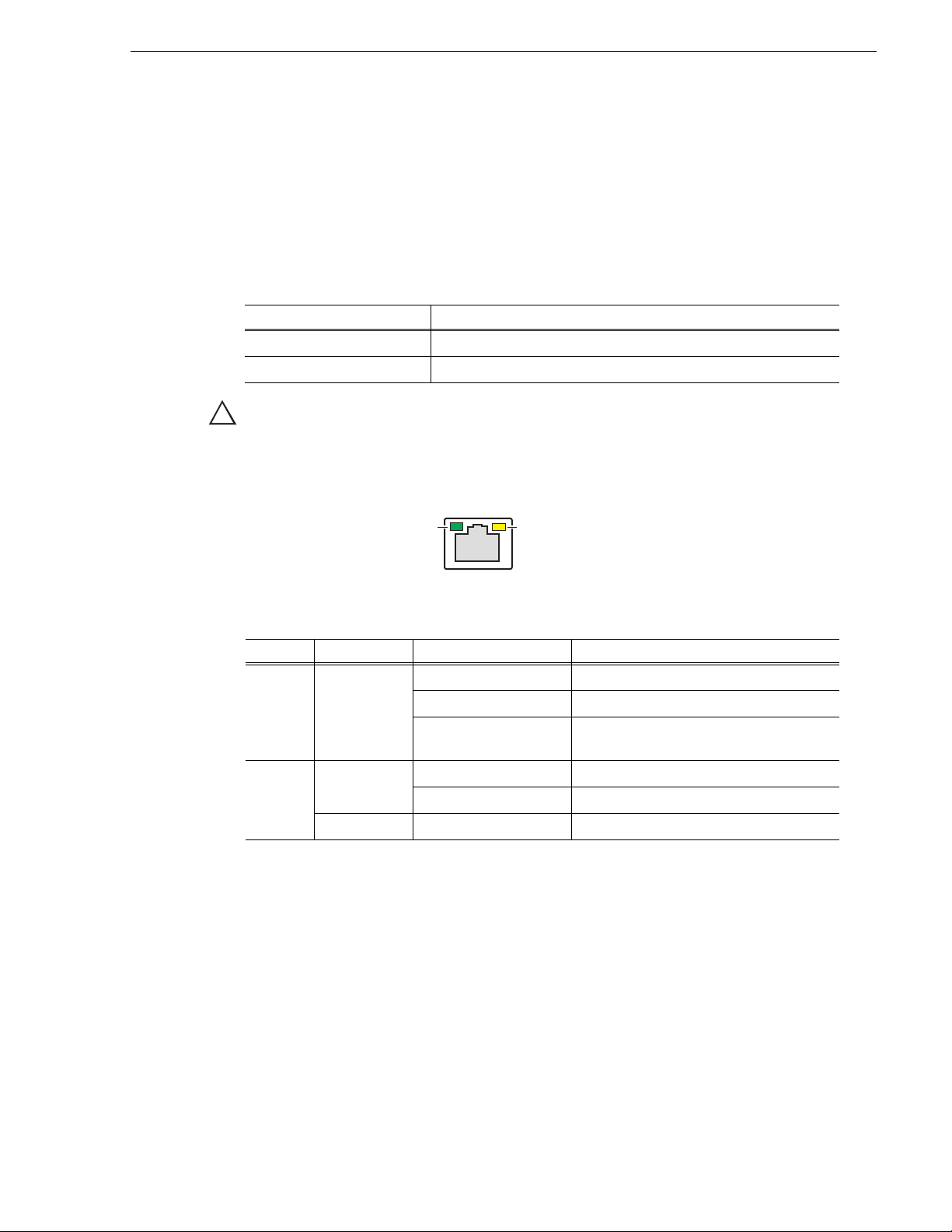
Status indicators
!
Green LED Green/Orange LED
The following sections describe the visual indicators that communicate the current
operating status and system health of the T2.
Power LED
The Power LED indicates status as follows:
LED behavior Status Condition
Off The power is set to Off and the T2 is not operational.
Green steady on The power is set to On and the T2 is operational.
WARNING: The power switch does not turn off power to the system. To turn power
off, the system must be disconnected from the power source.
LAN port indicator codes
The RJ-45 LAN port includes integrated status LEDs. The LEDs oriented as follows:
Status indicators
The meanings of the LED states are described in the following table:
LED Color LED state Status Condition
Left Green Off LAN link is not established.
On LAN link is established.
Flashing The computer is communicating with
another computer on the LAN.
Right Green Off 10 Mbit/sec data rate is selected.
On 100 Mbit/sec data rate is selected.
Orange On 1000 Mbit/sec data rate is selected.
If the LAN is faulty, you must replace the motherboard.
May 16, 2016 T2 Elite 2/Pro 2/Express 2/Elite/Pro/Express Service Manual 23
Page 24

Chapter 1 Product Description
24 T2 Elite 2/Pro 2/Express 2/Elite/Pro/Express Service Manual May 16, 2016
Page 25

Chapter 2
Maintenance Procedures
This chapter consists of the following:
• "Cleaning the touch screen LCD" on page 26
• "Starting and exiting the maintenance mode" on page 26
• "Starting the maintenance mode" on page 27
• "Exiting the maintenance mode" on page 28
• "Using the Maintenance Tools" on page 30
• "Launching the Maintenance Tools" on page 30
• "Closing the Maintenance Tools" on page 30
• "Media drive maintenance" on page 31
• "Data maintenance" on page 34
• "System related maintenance" on page 40
• "Using the Windows desktop" on page 44
• "Verifying, building, and rebuilding a RAID volume" on page 44
• "Verifying the RAID volume" on page 44
• "Building the RAID volume" on page 47
• "Rebuilding the RAID volume (for only the T2 Pro 2/Pro)" on page 54
• "Restoring to the factory default condition" on page 59
• "Recovery procedure for T2 Elite/Pro/Express" on page 59
• "Recovery procedure for T2 Elite 2/Pro 2/Express 2" on page 66
• "T2 Recovery Utility for T2 Elite 2/Pro 2/Express 2" on page 68
May 16, 2016 T2 Elite 2/Pro 2/Express 2/Elite/Pro/Express Service Manual 25
Page 26

Chapter 2 Maintenance Procedures
!
Cleaning the touch screen LCD
Build up of foreign objects such as soil and dust or dirt such as fingerprints on the
touch screen LCD may cause malfunction. Perform cleaning of the touch screen LCD
periodically, noting the following points:
• The surface of the touch screen LCD must be wiped with a clean cloth
dampened with a mild detergent. Do not apply a detergent directly onto the
touch screen LCD.
• Do not use any detergent containing abrasives. Abrasives may scratch the
surface of the display and decrease its visibility.
• Avoid getting water on the surface of the touch screen LCD. Moisture entered
into the system will cause a failure.
Starting and exiting the maintenance mode
The T2 has the following startup modes: normal and maintenance modes. Start up
your system in the appropriate mode depending on the purpose of use.
• Normal mode
The CommandCenter is launched automatically allowing you to perform
operations such as recording, playback, or editing.
• Maintenance mode
The Maintenance Tools is launched automatically allowing you to perform
maintenance operations of the T2. In the maintenance mode, you can also
perform operations such as using the Windows OS (such as configuring the
Date/Time) or building/rebuilding a RAID volume.
CAUTION: The T2 is not a general purpose Windows workstation. The T2 is
designed so that a user can start it up without an administrator privilege to log on
to the system automatically.
Grass Valley. A partial or total system failure may result.
- Do not use the User Accounts on the T2.
- Do not install any third party software not provided by Grass Valley on the T2.
- Do not install any Windows updates on the T2.
Do not modify any system settings unless approved by
26 T2 Elite 2/Pro 2/Express 2/Elite/Pro/Express Service Manual May 16, 2016
Page 27
Starting the maintenance mode
!
Restart the T2 in the maintenance mode from CommandCenter to run the maintenance
mode. This section mainly describes the procedures using the touch screen LCD.
CAUTION: You must finish all of the playback and recording operations to stop the
media access prior to performing operations.
Starting and exiting the maintenance mode
1. Switch to
1ch View, touch Menu
, and then
• When operating in the workstation mode, click System from the menu bar and
then click
Maintenance....
2. Touch the entry field on the password entry screen.
3. Enter "admin", and touch
4. Touch
5. Touch
OK.
Yes when the confirmation message is displayed.
OK.
• The CommandCenter is closed and the system restarts in the maintenance
mode.
• Connect a mouse or keyboard, if necessary.
• After the restart, the Maintenance Tools is launched automatically.
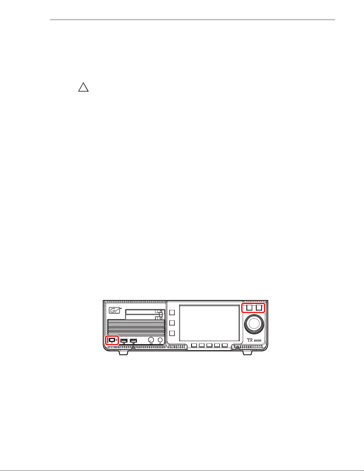
Forcing startup of the maintenance mode
If you cannot start the maintenance mode with procedures above, perform the
following steps.
1. Turn on the power of the T2 while pressing the
the same time.
• Keep pressing the
Shuttle/Jog and VAR buttons until a message "Now
switching to Maintenance mode. The system is rebooting..." is displayed in the
touch screen LCD.
touch
Tools
J
Maintenance
Shuttle/Jog and VAR buttons at
.
• The T2 will start in the maintenance mode.
May 16, 2016 T2 Elite 2/Pro 2/Express 2/Elite/Pro/Express Service Manual 27
Page 28
Chapter 2 Maintenance Procedures
!
Exiting the maintenance mode
CAUTION: You must finish a diagnosis using the Maintenance Tools prior to
exiting the maintenance mode.
Restarting from the maintenance mode to the normal mode
The operation to switch from the maintenance mode to the normal mode is performed
from the Maintenance Tools main screen.
NOTE: You need to launch the Maintenance Tools beforehand. For more
information, refer to "Launching the Maintenance Tools" on page 30.
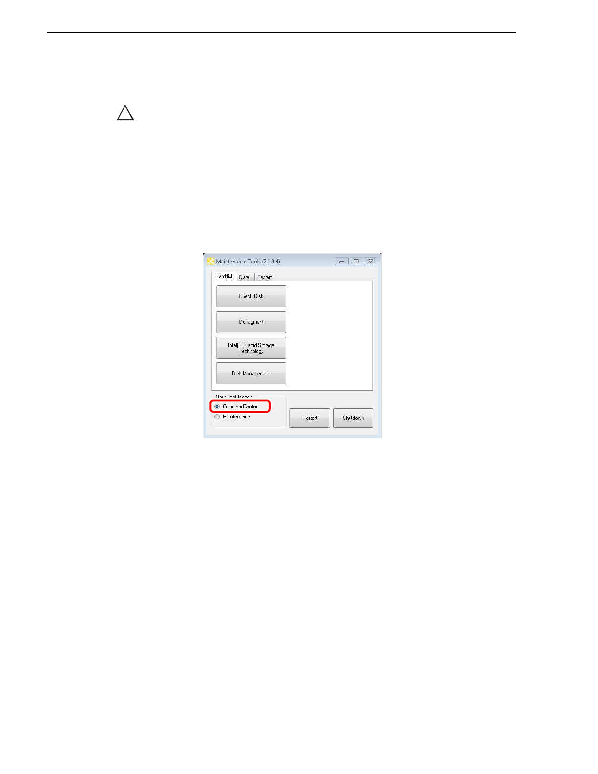
1. In the Maintenance Tools main screen, select CommandCenter under "Next Boot
Mode".
2. Click
Starting up the system without exiting the maintenance mode
This section describes the procedure to restart your system in the maintenance mode
from the Maintenance Tools main screen.
NOTE: If the Maintenance Tools is not running in the maintenance mode,
performing the normal restart operation from the Windows desktop will restart your
system without exiting the maintenance mode.
Restart.
• After the restart, the CommandCenter is launched automatically.
28 T2 Elite 2/Pro 2/Express 2/Elite/Pro/Express Service Manual May 16, 2016
Page 29
Starting and exiting the maintenance mode
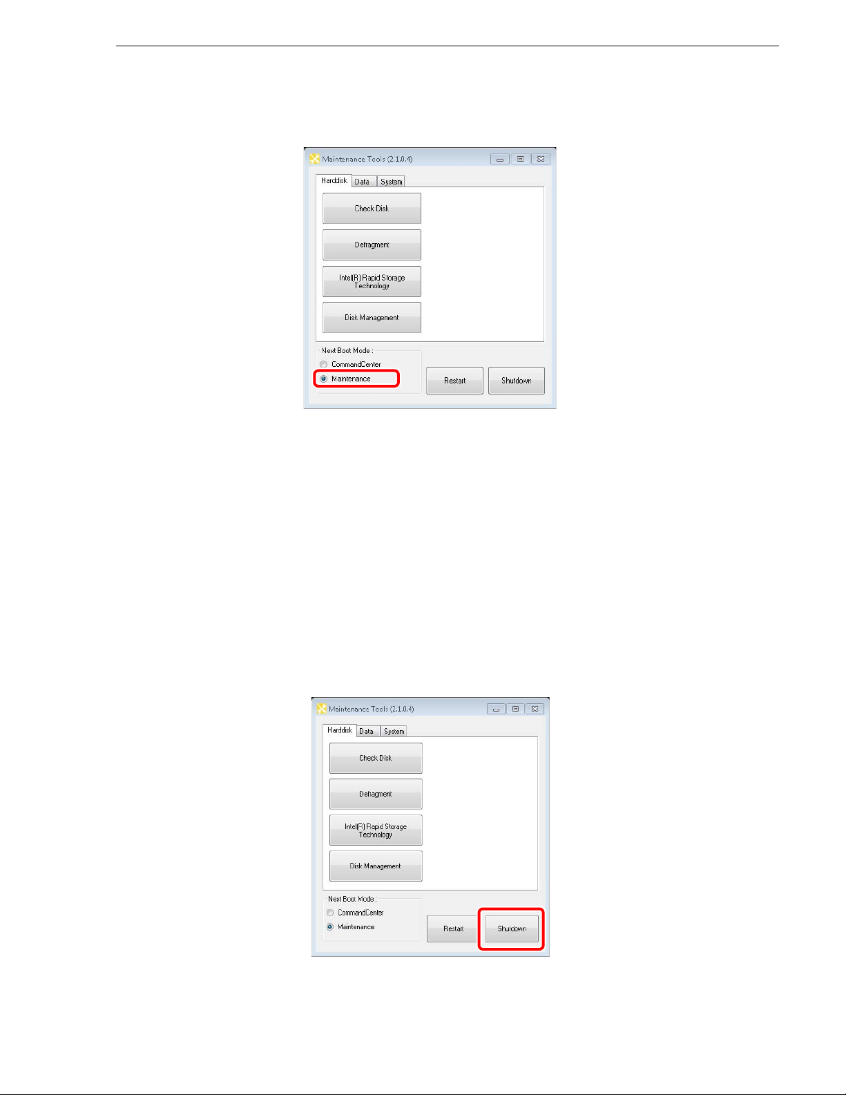
1. In the Maintenance Tools main screen, select Maintenance under "Next Boot
Mode".
2. Click
Restart
.
• After the restart, the Maintenance Tools is launched automatically.
Exiting the maintenance mode to shut down
You can exit the maintenance mode from the Maintenance Tools main screen to shut
down the T2.
NOTE: If the Maintenance Tools is not running in the maintenance mode,
performing the normal shutdown operation from the Windows desktop will shut
down your system. The T2 will restart in the maintenance mode.
1. In the Maintenance Tools main screen, click
• You can select the next boot mode. Select
in the normal mode. Select
Maintenance to startup the T2 in the maintenance
mode.
Shutdown
CommandCenter to startup the T2
.
May 16, 2016 T2 Elite 2/Pro 2/Express 2/Elite/Pro/Express Service Manual 29
Page 30

Chapter 2 Maintenance Procedures
Using the Maintenance Tools
The Maintenance Tools is software for performing maintenance procedures such as
running a failure diagnosis on the T2 or backing up data.
You can perform the following procedures using the Maintenance Tools. Refer to the
specific topics for more information.
• Media drive maintenance
- "Media disk error checks" on page 31
- "Defragmentation of media disk" on page 32
• Data maintenance
- "Checking the data consistency" on page 34
- "Initializing the data" on page 36
- "Backing up the data" on page 37
- "Restoring the data" on page 39
• System related maintenance
- "Acquiring the system information" on page 40
- "Exporting log files" on page 42
- "Date and Time" on page 43
Launching the Maintenance Tools
The Maintenance Tools is launched automatically when you start the maintenance
mode. This section describes the procedure to the launch the Maintenance Tools again
when the Maintenance Tools is closed in the maintenance mode (from the Windows
desktop).
For more information on how to start the maintenance mode, refer to "Starting the
maintenance mode" on page 27.
NOTE: A mouse must be connected to your T2 beforehand.
1. Double-click the Maintenance Tools icon on the Windows desktop.
NOTE: You can also launch the Maintenance Tools by double-clicking C:/Eiger/
Eiger.Mainte.ToolMain.exe.
• The Maintenance Tools is launched.
Closing the Maintenance Tools
This section describes the procedure to close the Maintenance Tools and to display
the Windows desktop.
For more information on how to exit the maintenance mode, refer to "Exiting the
maintenance mode" on page 28.
30 T2 Elite 2/Pro 2/Express 2/Elite/Pro/Express Service Manual May 16, 2016
Page 31

Using the Maintenance Tools
!
CAUTION: You must finish a diagnosis using the Maintenance Tools prior to
closing the Maintenance Tools.
1. In the Maintenance Tools main screen, click
• The Maintenance Tools is closed and the Windows desktop appears.
Media drive maintenance
Media disk error checks
You can scan the media disk to check it for any file system errors and bad sectors,
targeting the data drive (V: drive). If any error is found, the system attempts to fix the
media disk.
X.
1. In the Maintenance Tools main screen, click the
Harddisk tab.
May 16, 2016 T2 Elite 2/Pro 2/Express 2/Elite/Pro/Express Service Manual 31
Page 32

Chapter 2 Maintenance Procedures
!
2. Click Check Disk.
3. Check the items under "Options" as necessary, and then click
Fix file system errors is checked, the system fixes errors automatically
• If
without scanning for bad sectors.
• To abort a check in the middle of performing it, click
4. When you see the completion message, click
• "Check disk for Data Drive" screen is closed.
Defragmentation of media disk
You can defragment the media disk, targeting the data drive (V drive).
Start.
Abort.
Close.
CAUTION: Do not defragment the media disk of the T2 Elite 2/Elite model.
Defragmentation could shorten the life of an SSD.
32 T2 Elite 2/Pro 2/Express 2/Elite/Pro/Express Service Manual May 16, 2016
Page 33

Using the Maintenance Tools
1. In the Maintenance Tools main screen, click the Harddisk tab.
2. Click
Defragment.
3. Click either
Analyze or Defragment.
May 16, 2016 T2 Elite 2/Pro 2/Express 2/Elite/Pro/Express Service Manual 33
Page 34

Chapter 2 Maintenance Procedures
• Clicking Analyze performs only a defragmentation analysis. The analysis
result is displayed on the screen.
• Clicking
Defragment performs defragmentation. The progress of
defragmentation is displayed on the screen.
• To abort a process in the middle of performing it, click
4. When you see the completion message, click
• "Defragment" screen is closed.
Data maintenance
Checking the data consistency
You can check the consistency between the database information and the actual media
files. This allows you to list information or media files that exist in only either of them
and to delete them.
NOTE: Data in the Recycle Bin is not subject to this data consistency check.
1. In the Maintenance Tools main screen, click the
Abort.
Close.
Data tab.
34 T2 Elite 2/Pro 2/Express 2/Elite/Pro/Express Service Manual May 16, 2016
Page 35

2. Click Consistency Check.
Using the Maintenance Tools
3. Click
Check Consistency.
• A data consistency check begins and any inconsistent information is listed on
the screen.
4. Check the inconsistent information you want to delete, and then click
Exec Delete.
• You can select all of the listed information by clicking
• You can deselect all of the listed information by clicking
Select All.
Unselect All
.
5. Click Close.
• "Consistency Check" screen is closed.
May 16, 2016 T2 Elite 2/Pro 2/Express 2/Elite/Pro/Express Service Manual 35
Page 36

Chapter 2 Maintenance Procedures
!
Initializing the data
You can initialize the database, the data drive (V: drive), and the Config settings.
CAUTION: Initializing your data will delete all of the current data. You should
back up your data beforehand as necessary.
1. In the Maintenance Tools main screen, click the
2. Click
Initialize.
Data tab.
3. Check the items you want to initialize under "Target".
36 T2 Elite 2/Pro 2/Express 2/Elite/Pro/Express Service Manual May 16, 2016
Page 37

• Check Database to delete the contents of the database.
Using the Maintenance Tools
• Check
• Check
• Check
of the keyboard shortcuts and mouse customization.
• Check
Schedule Recording function automatically starts capturing operation at a
specified time, and ends it at a specified time in the R1-live mode. For more
information, refer to the T2 User Manual.
• Multiple items can be selected.
4. Click
5. Click
Initialize.
Yes when the confirmation message is displayed.
• The initialization is performed.
6. When you see the completion message, click
7. Click
Close.
• "Data Initialize" screen is closed.
Backing up the data
You can back up the database, the media files in the data drive (V: drive), and the
Config settings.
Media drive to format the data drive and initialize the folder structure.
Configuration to initialize the settings of Config.
Customize Keyboard Shortcuts and Mouse to initialize the settings
Schedule to initialize the settings of Schedule Recording.
OK.
1. In the Maintenance Tools main screen, click the
Data tab.
May 16, 2016 T2 Elite 2/Pro 2/Express 2/Elite/Pro/Express Service Manual 37
Page 38

Chapter 2 Maintenance Procedures
2. Click Backup.
3. Click ... to specify the destination to save your backup data.
4. Check the target item(s) you want to back up under "Backup Targets".
• Checking
• Checking
Database will back up the database.
Media, Thumbnail files will back up the media files including the
thumbnails.
• Checking
• Check
Configuration will back up the Config settings.
Keyboard Shortcuts and Mouse Customize to back up the settings of
the keyboard shortcuts and mouse customization.
• Multiple items can be selected.
5. Click
6. Click
Backup.
Yes when the confirmation message is displayed.
• The backup begins and the progress is displayed.
7. When you see the completion message, click
OK.
• A folder, that stores an XML file containing the backup information and the
backup data, is created in the specified destination. The folder name will be the
saved date (yyyymmdd).
8. Click
Close.
• "Data Backup" screen is closed.
38 T2 Elite 2/Pro 2/Express 2/Elite/Pro/Express Service Manual May 16, 2016
Page 39

Restoring the data
You can restore the data of your backed up database, media files, and Config settings.
CAUTION: Restoring your data will delete all of the current data overwriting it
!
with the source data for the restore.
Using the Maintenance Tools
1. In the Maintenance Tools main screen, click the
2. Click
Restore.
Data tab.
3. Click
Select to specify the XML file created upon the backup.
May 16, 2016 T2 Elite 2/Pro 2/Express 2/Elite/Pro/Express Service Manual 39
Page 40

Chapter 2 Maintenance Procedures
• "Backup timestamp" shows the backup date.
• Among the items under "Restore Targets", any item(s) that exist in the same
folder where the XML file is located will be checked.
4. Make sure that the data you want to restore are checked under "Restore Targets".
• Uncheck any item that does not need to be restored.
5. Click
6. Click
Restore.
Yes when the confirmation message is displayed.
• The restore begins.
7. When you see the completion message, click
8. Click
Close.
• "Data Restore" screen is closed.
System related maintenance
Acquiring the system information
You can acquire the system information of the Windows OS (such as the hardware
information, components, and software environment) and save it in text format.
1. In the Maintenance Tools main screen, click the
OK.
System tab.
40 T2 Elite 2/Pro 2/Express 2/Elite/Pro/Express Service Manual May 16, 2016
Page 41

2. Click System Information.
Using the Maintenance Tools
3. Click
4. Click
... to specify the destination to save the system information and a file name.
Save.
• The progress bar shows the status of the system information acquirement.
5. When you see the completion message, click
OK.
• A text format file containing the system information is created in the specified
destination.
6. Click
Close.
• "System Information" screen is closed.
May 16, 2016 T2 Elite 2/Pro 2/Express 2/Elite/Pro/Express Service Manual 41
Page 42

Chapter 2 Maintenance Procedures
Exporting log files
You can export an operation log, Windows OS internal event log, database log, and
crash dumps message log.
1. In the Maintenance Tools main screen, click the
2. Click
Log Export.
System tab.
3. Check the log(s) you want to export under "Export targets".
• Checking
42 T2 Elite 2/Pro 2/Express 2/Elite/Pro/Express Service Manual May 16, 2016
Application logs will export an operation log.
Page 43

Using the Maintenance Tools
• Checking Event logs will export a Windows OS internal event log.
• Checking
• Checking
• Multiple items can be selected.
4. Click
5. Click
• The progress bar shows the exporting status.
6. When you see the completion message, click
• A ZIP file containing the log files is created in the specified destination.
7. Click
• "Log Export" screen is closed.
NOTE: You can check the operation log while the T2 is running in the workstation
mode. Click
the "Log Viewer" screen appears, select the desired log file to view the operation
log.
Date and Time
You can set the date and time of T2 built-in clock.
SQL Server logs will export a database log.
Crash dumps will export a crash dumps message log.
... to specify the destination to save the log and a file name.
Save.
OK.
Close.
Option from the menu bar, and then click Log J Show Log....Once
1. In the Maintenance Tools main screen, click the
System tab.
May 16, 2016 T2 Elite 2/Pro 2/Express 2/Elite/Pro/Express Service Manual 43
Page 44

Chapter 2 Maintenance Procedures
2. Click Date and Time.
• On the "Date and Time" screen of the Windows OS that appears, change the
date and time, and TimeZone.
3. Click
OK.
• "Date and Time" screen is closed.
Using the Windows desktop
In the maintenance mode, you can use the standard Windows OS functions, using the
Windows desktop.
The Windows desktop will become available when the Maintenance Tools is closed
after starting up the system in the maintenance mode. For more information, refer to
"Starting the maintenance mode" on page 27 and "Closing the Maintenance Tools" on
page 30.
Verifying, building, and rebuilding a RAID volume
The T2 has a function to monitor the RAID volume and monitors it all the time while
the CommandCenter is running. If any problem occurs on the RAID volume, the icon
( ) is displayed at the right of the screen for the Front Panel Mode or on the status
bar of the Workstation Mode to notify that a part of the drive that configures the RAID
volume is not recognized. If multiple drives cannot be recognized and the RAID
volume cannot be configured, the T2 starts up in the maintenance mode even when
starting up in the normal mode. Following the procedure described below, you can
verify the RAID volume to identify any failed drive(s) and build or rebuild the RAID
volume after replacing the failed drive.
Verifying the RAID volume
You can verify the current condition of the RAID volume to identify the failed drive(s).
This section describes an example of the procedure for T2 Pro, which also applies to
other models.
44 T2 Elite 2/Pro 2/Express 2/Elite/Pro/Express Service Manual May 16, 2016
Page 45

Verifying, building, and rebuilding a RAID volume
NOTE: A mouse must be connected to your T2 beforehand.
1. Start up the T2 in the maintenance mode.
• For more information, refer to "Starting the maintenance mode" on page 27.
2. In the Maintenance Tools main screen, click the
Intel(R) Rapid Storage Technology.
• The Intel(R) Rapid Storage Technology is launched.
Harddisk tab, and then click
May 16, 2016 T2 Elite 2/Pro 2/Express 2/Elite/Pro/Express Service Manual 45
Page 46

Chapter 2 Maintenance Procedures
3. Click the device with the "!" mark in "Storage System View" at the right of the
screen.
• The numbers in "Port 1", "Port 2"...etc. are their drive numbers. The drives are
sorted in the order of "SATA 0", "SATA 1" ...
• For a drive running normally, "Normal" is shown for "Status" of "Manage
Disk" at the left of the screen, and for a failed drive, "Missing" is shown. In this
example, the drive 1 (Port 1) is failed.
• If there is any failed drive, shut down the T2 as described in "Exiting the
maintenance mode to shut down" on page 29, then replace the failed drive as
described in "HDD/SSD (for data) removal" on page 94. For the T2 Elite 2/
Express 2/Elite/Express, build the RAID volume after the drive replacement as
described in "Building the RAID volume" on page 47. For the T2 Pro 2/Pro,
rebuild the RAID volume as described in "Rebuilding the RAID volume (for
only the T2 Pro 2/Pro)" on page 54.
46 T2 Elite 2/Pro 2/Express 2/Elite/Pro/Express Service Manual May 16, 2016
Page 47

Building the RAID volume
For the T2 Elite 2/Express 2/Elite/Express, rebuild the RAID volume after the drive
replacement.
This section describes the procedure for the T2 Express as an example, but the
procedure for the T2 Elite 2/Express 2/Elite is the same.
NOTE: A mouse and keyboard must be connected to your T2 beforehand.
1. Start up the T2 in the maintenance mode.
• For more information, refer to"Starting the maintenance mode" on page 27.
Verifying, building, and rebuilding a RAID volume
2. In the Maintenance Tools main screen, click the
Intel(R) Rapid Storage Technology.
• The Intel(R) Rapid Storage Technology is launched.
Harddisk tab, and then click
May 16, 2016 T2 Elite 2/Pro 2/Express 2/Elite/Pro/Express Service Manual 47
Page 48

Chapter 2 Maintenance Procedures
3. Click the device with "Internal disk" in "Storage System View" at the right of the
screen.
• Check whether the replaced drive is recognized.
4. Click the "Data Type: RAID 0" section in "Storage System View" at the right of
the screen.
48 T2 Elite 2/Pro 2/Express 2/Elite/Pro/Express Service Manual May 16, 2016
Page 49

Verifying, building, and rebuilding a RAID volume
5. Click Delete volume in "Manage Volume" at the left of the screen.
6. Click
7. Click
Yes when the confirmation message is displayed.
Create.
May 16, 2016 T2 Elite 2/Pro 2/Express 2/Elite/Pro/Express Service Manual 49
Page 50

Chapter 2 Maintenance Procedures
8. Select Optimized disk performance (RAID 0), and click Next..
• For the T2 Pro 2/Pro, select
(RAID 10)
.
Balanced performance and data protection
9. Enter "DATA" in "Name", and check
two to six disks:", and then click
Next.
Disk on port 0 and Disk on port 1 in "Select
• For the T2 Pro 2/Pro, check
and
Disk on port 3 in "Select two to six disks:".
Disk on port 0, Disk on port 1, Disk on port 2,
50 T2 Elite 2/Pro 2/Express 2/Elite/Pro/Express Service Manual May 16, 2016
Page 51

10. Click Create Volume.
Verifying, building, and rebuilding a RAID volume
11. Click
12. Confirm the RAID is rebuilt.
OK.
• Rebuilding of the RAID is completed. Next, allocate the drive.
May 16, 2016 T2 Elite 2/Pro 2/Express 2/Elite/Pro/Express Service Manual 51
Page 52

Chapter 2 Maintenance Procedures
13. In the Maintenance Tools main screen, click the Harddisk tab, and then click Disk
Management
.
14. Check
Disk 0, and select GPT (GUID Partition Table), and then click OK.
• If the "Initialize Disk" dialog box does not appear, click
from the right-click menu.
Disk
15. Right-click the unallocated space, and click
New Simple Volume....
Disk 0, select Initialize
52 T2 Elite 2/Pro 2/Express 2/Elite/Pro/Express Service Manual May 16, 2016
Page 53

Verifying, building, and rebuilding a RAID volume
16. Click Next.
17. Enter the maximum value of the drive space in "Simple volume size in MB:", and
Next.
enter
18. Select
click
Assign the following drive letter: , and select "V" from the list, and then
Next.
May 16, 2016 T2 Elite 2/Pro 2/Express 2/Elite/Pro/Express Service Manual 53
Page 54

Chapter 2 Maintenance Procedures
!
19. Select Format this volume with the following settings, and set the items as
follows.
• Select "NTFS" from the "File system:" list, and select "Default" from the
"Allocation unit size:" list.
• Enter "DATA" in "Volume label:".
• Check
20. Click
21. Click
Perform a quick format.
Next.
Finish.
• When formatting is finished, the drive allocation is completed.
Rebuilding the RAID volume (for only the T2 Pro 2/Pro)
For the T2 Pro 2/Pro, the drives with drive numbers "0" and "1" and the drives with
drive numbers "2" and "3" are paired respectively, which allows you to rebuild the
RAID volume using another paired drive even if one of the paired drives fails.
This section describes the procedure to rebuild the RAID volume after drive
replacement.
NOTE: A mouse must be connected to your T2 beforehand.
CAUTION: If a failure occurs on both of the drives with drive numbers "0" and
"1" or the drives with drive numbers "2" and "3" at the same time, it is impossible
to repair the RAID volume. You need to build a RAID volume as described in
"Building the RAID volume" on page 47.
54 T2 Elite 2/Pro 2/Express 2/Elite/Pro/Express Service Manual May 16, 2016
Page 55

Verifying, building, and rebuilding a RAID volume
1. Start up the T2 in the maintenance mode.
• For more information, refer to "Starting the maintenance mode" on page 27.
2. In the Maintenance Tools main screen, click the
Intel(R) Rapid Storage Technology.
• The Intel(R) Rapid Storage Technology is launched.
Harddisk tab, and then click
May 16, 2016 T2 Elite 2/Pro 2/Express 2/Elite/Pro/Express Service Manual 55
Page 56

Chapter 2 Maintenance Procedures
3. Click the device with "Internal disk" in "Storage System View" at the right of the
screen.
4. Click
screen.
5. Click
Mark as spare for "Usage: Available" in "Manage Disk" at the left of the
Yes.
56 T2 Elite 2/Pro 2/Express 2/Elite/Pro/Express Service Manual May 16, 2016
Page 57

Verifying, building, and rebuilding a RAID volume
• The rebuild of the RAID drive begins.
• The rebuild of the RAID takes about two hours for replacement of a HDD (500 GB).
6. Click Status.
• The rebuild progress appears.
7. Confirm the rebuild is completed.
• The device where the "!" mark is displayed in "Storage System View"
disappears.
May 16, 2016 T2 Elite 2/Pro 2/Express 2/Elite/Pro/Express Service Manual 57
Page 58

Chapter 2 Maintenance Procedures
8. Click Manage.
9. Click the device of the replaced drive number from "Storage System View" at the
right of the screen.
• Confirm "Status" is "Normal" in "Manage Disk" at the left of the screen.
58 T2 Elite 2/Pro 2/Express 2/Elite/Pro/Express Service Manual May 16, 2016
Page 59

Restoring to the factory default condition
Restoring to the factory default condition
This section describes the procedure to restore (or recover) the T2 to the factory
default condition using the recovery UFD (USB Flash Drive).
The recovery UFD is built in T2.
NOTE: A mouse and keyboard must be connected to your T2 beforehand.
NOTE: A recovery does not initialize the contents of the data drive (V: drive). If you
want to initialize the data drive, refer to "Initializing the data" on page 36.
CAUTION: Do not connect any external storage device via USB, 2.5 inch
!
removable SSD bay, or the media card reader when restoring to the factory default
condition.
CAUTION: A recovery will initialize all of the data below. You should back up your
!
data to an external storage device beforehand as necessary.
- Database
- Config settings
- Logs (the operation log, Windows OS internal event log, database log, and
crash dumps)
The recovery procedure differs depending on the model. For more information, see
the reference.
• "Recovery procedure for T2 Elite/Pro/Express" on page 59
• "Recovery procedure for T2 Elite 2/Pro 2/Express 2" on page 66
Recovery procedure for T2 Elite/Pro/Express
1. Turn the T2 on.
• Turn on the power switch of the front panel.
NOTE: Make sure that no media is inserted in the 2.5 inch removable SSD bay.
NOTE: Make sure that any device other than the keyboard and mouse is not
connected to the USB port.
2. Press the [F7] key on the keyboard a few times when POST screen is displayed.
• The Boot Menu (Please select boot device:) appears.
3. Select the recovery UFD using the [K] or [L] key, and then press the [Enter] key.
May 16, 2016 T2 Elite 2/Pro 2/Express 2/Elite/Pro/Express Service Manual 59
Page 60

Chapter 2 Maintenance Procedures
4. When "About Recover Tool" screen is displayed, click OK.
5. Click
Local, and then click Disk J From Image.
• "Image file name to restore from" screen appears.
60 T2 Elite 2/Pro 2/Express 2/Elite/Pro/Express Service Manual May 16, 2016
Page 61

Restoring to the factory default condition
6. Choose the drive "F: 3.1[: RECOVERY] NTFS drive" that contains the recovery
image.
7. Select a GHO format file located directly under the F: drive, and then click
• "Select local destination drive by clicking on the drive number" screen appears.
Open.
May 16, 2016 T2 Elite 2/Pro 2/Express 2/Elite/Pro/Express Service Manual 61
Page 62

Chapter 2 Maintenance Procedures
!
8. Select the SSD (for the system), and then click OK.
• "Destination Drive Details" screen appears.
CAUTION: Be sure to select SSD (for the system) as the recovery destination as in
the screen above. If a wrong recovery destination is selected, the system may not be
able to be restored.
9. Confirm that the value in the "New Size" for the D: drive is larger than that of the
"Old Size" for the D: drive.
62 T2 Elite 2/Pro 2/Express 2/Elite/Pro/Express Service Manual May 16, 2016
Page 63

Restoring to the factory default condition
10. Confirm that the value in the "New Size" for the E: drive is larger than that of the
"Old Size" for the E: drive.
11. Click
OK.
May 16, 2016 T2 Elite 2/Pro 2/Express 2/Elite/Pro/Express Service Manual 63
Page 64

Chapter 2 Maintenance Procedures
12. Click Yes when the confirmation message is displayed.
• The writing process of the recovery image is performed. This process will take
a while.
64 T2 Elite 2/Pro 2/Express 2/Elite/Pro/Express Service Manual May 16, 2016
Page 65

Restoring to the factory default condition
13. Click Reset Computer.
• The T2 restarts and a batch process for SID generation, the drive letter
assignment, and virtual memory allocation will run.
14. When you see the message "Press any key to continue...", confirm the drive
structure is the following.
15. Press any key on the keyboard and restart the T2.
• The T2 will restart in the maintenance mode.
• If you want to start up the T2 system in the normal mode, switch to the normal
mode after starting up the maintenance mode. For detailed instructions, refer to
"Restarting from the maintenance mode to the normal mode" on page 28.
NOTE: It is recommended to initialize the data after the recovery is completed. For
detailed instructions, refer to "Initializing the data" on page 36.
NOTE: Media files in the data drive (V: drive) cannot be used as they are even after
the recovery is completed. Copy the media files to the external storage device, and
then import them using the CommandCenter. For detailed instructions, refer to the
T2 User Manual.
May 16, 2016 T2 Elite 2/Pro 2/Express 2/Elite/Pro/Express Service Manual 65
Page 66

Chapter 2 Maintenance Procedures
Recovery procedure for T2 Elite 2/Pro 2/Express 2
1. Turn the T2 on.
• Turn on the power switch of the front panel.
NOTE: For T2 Elite 2, make sure that no media is inserted in the media card
reader.
NOTE: Make sure that any device other than the keyboard and mouse is not
connected to the USB port.
2. When the POST screen appears, hold down the [F7] key on the keyboard.
• The Boot Menu (Please select boot device:) appears.
3. Select the recovery UFD using the [K] or [L] key, and then press the [Enter] key.
4. On the "TOP" page, press the [1] key and then press the [Enter] key on the
keyboard.
66 T2 Elite 2/Pro 2/Express 2/Elite/Pro/Express Service Manual May 16, 2016
Page 67

Restoring to the factory default condition
5. When the message "Are you sure you want to restore?" appears, press the [y] key
and then press the [Enter] key on the keyboard.
• The write-back process of the recovery image is performed. This process will
take a while.
• When the write-back process of the recovery image is completed, T2 will be
restarted a few times.
6. When you see the message "Press any key to continue...", confirm the drive
structure is the following.
7. Press any key on the keyboard and restart the T2.
• The T2 will restart in the maintenance mode.
• If you want to start up the T2 system in the normal mode, switch to the normal
mode after starting up the maintenance mode. For detailed instructions, refer to
"Restarting from the maintenance mode to the normal mode" on page 28.
NOTE: It is recommended to initialize the data after the recovery is completed. For
detailed instructions, refer to "Initializing the data" on page 36.
NOTE: Media files in the data drive (V: drive) cannot be used as they are even after
the recovery is completed. Copy the media files to the external storage device, and
then import them using the CommandCenter. For detailed instructions, refer to the
T2 User Manual.
May 16, 2016 T2 Elite 2/Pro 2/Express 2/Elite/Pro/Express Service Manual 67
Page 68

Chapter 2 Maintenance Procedures
T2 Recovery Utility for T2 Elite 2/Pro 2/Express 2
T2 Recovery Utility is included in the recovery UFD for T2 Elite 2/Pro 2/Express 2.
The following operations can be performed with T2 Recovery Utility. For more
information, see the reference.
• Automatic recovery ( page 66)
• Manual recovery ( page 69)
• Command prompt execution ( page 70)
• Disk formatting ( page 71)
Starting up T2 Recovery Utility
1. Turn the T2 on.
• Turn on the power switch of the front panel.
NOTE: For T2 Elite 2, make sure that no media is inserted in the media card
reader.
NOTE: Make sure that any device other than the keyboard and mouse is not
connected to the USB port.
2. When the POST screen appears, hold down the [F7] key on the keyboard.
• The Boot Menu (Please select boot device:) appears.
3. Select the recovery UFD using the [K] or [L] key, and then press the [Enter] key.
• The "TOP" page of the "T2 Recovery Utility" screen appears.
68 T2 Elite 2/Pro 2/Express 2/Elite/Pro/Express Service Manual May 16, 2016
Page 69

Exiting T2 Recovery Utility
1. On the "TOP" page of the "T2 Recovery Utility" screen, press the [3] key and then
press the [Enter] key on the keyboard.
2. When the message "Please press any key to exit." appears, press any key on the
keyboard.
• T2 will shut down automatically.
Restoring to the factory default condition
Manual recovery
You can select the recovery image and recovery destination manually to restore the
factory default condition.
Normally, follow the procedure "Recovery procedure for T2 Elite 2/Pro 2/Express 2"
on page 66 to restore the factory default condition.
1. Start up T2 Recovery Utility.
• For more information, see "Starting up T2 Recovery Utility" on page 68.
2. On the "TOP" page, press the [2] key and then press the [Enter] key on the
keyboard.
May 16, 2016 T2 Elite 2/Pro 2/Express 2/Elite/Pro/Express Service Manual 69
Page 70

Chapter 2 Maintenance Procedures
!
3. On the "Advanced" page, press the [1] key and then press the [Enter] key on the
keyboard.
• Press the [4] key on the "Advanced" page to go back to the "TOP" page.
4. Perform steps 4 and later in "Recovery procedure for T2 Elite/Pro/Express" on
page 59.
CAUTION: If recovery has been performed on the SSD/HDD for data by accident,
try reformatting of the data disk. For more information, see "Disk formatting" on
page 71.
Executing command prompt
1. Start up T2 Recovery Utility.
• For more information, see "Starting up T2 Recovery Utility" on page 68.
2. On the "TOP" page, press the [2] key and then press the [Enter] key on the
keyboard.
70 T2 Elite 2/Pro 2/Express 2/Elite/Pro/Express Service Manual May 16, 2016
Page 71

3. On the "Advanced" page, press the [3] key and then press the [Enter] key on the
keyboard.
• A new window appears to allow various Windows command prompt
• To go back to the "Advanced" page, execute the "exit" command.
• Press the [4] key on the "Advanced" page to go back to the "TOP" page.
Disk formatting
Restoring to the factory default condition
operations.
1. Start up T2 Recovery Utility.
• For more information, see "Starting up T2 Recovery Utility" on page 68.
2. On the "TOP" page, press the [2] key and then press the [Enter] key on the
keyboard.
May 16, 2016 T2 Elite 2/Pro 2/Express 2/Elite/Pro/Express Service Manual 71
Page 72

Chapter 2 Maintenance Procedures
3. On the "Advanced" page, press the [2] key and then press the [Enter] key on the
keyboard.
• Press the [4] key on the "Advanced" page to go back to the "TOP" page.
4. On the "Drive Utility" page, press one of the [1] to [3] keys and then press the
[Enter] key on the keyboard.
• The operations executed by the [1] to [3] keys are as follows.
-[1]: Displays the list of the disks of T2. You can see the status, size, volume
letter and label of each disk.
-[2]: Executes quick formatting of the system drive (Disk 1).
-[3]: Executes quick formatting of the data drive (Disk 0) in the GPT format.
• Press the [4] key on the "Drive Utility" page to go back to the "Advanced"
page. Press the [5] key to go back to the "TOP" page.
72 T2 Elite 2/Pro 2/Express 2/Elite/Pro/Express Service Manual May 16, 2016
Page 73

Chapter 3
Troubleshooting Problems
If you think there is something wrong (broken) with your T2, go through the
following preliminary steps:
• "Step 1: Check configurations" on page 74
• "Step 2: Check connections and external equipment" on page 74
Then use the following topics to troubleshoot specific problem areas:
• "Shutdown/restart problems" on page 74
• "Checking external equipment" on page 75
• "PC monitor problems" on page 75
• "Keyboard problems" on page 75
• "Mouse problems" on page 76
• "Motherboard/BIOS startup" on page 76
• "Windows startup" on page 78
• "T2 system startup" on page 78
• "Thermal problems" on page 78
• "I/O board unit problems" on page 79
• "Power supply problems" on page 80
• "Front panel problems" on page 80
• "Touch screen LCD and control buttons problems" on page 80
• "Interconnect board problems" on page 81
• "2.5 inch removable SSD bay problems" on page 82
• "Media card reader problems" on page 83
• "Video problems" on page 83
• "Audio problems" on page 84
• "Timecode problems" on page 84
• "Operational problems" on page 85
• "System problems" on page 85
• "Storage problems" on page 86
• "Media File System problems" on page 86
• "Media disk problems" on page 86
• "Checking the storage system" on page 88
May 16, 2016 T2 Elite 2/Pro 2/Express 2/Elite/Pro/Express Service Manual 73
Page 74

Chapter 3 Troubleshooting Problems
Step 1: Check configurations
Many times what appears to be a T2 fault is actually an easy-to-fix configuration
problem. Refer to the T2 User Manual for operator tips that help you verify basic
configuration and correct common record/play problems.
Step 2: Check connections and external equipment
Loose or improperly connected cables are the most likely source of problems for the
system, monitor, or other external equipment. A quick check of all the cable
connections can easily solve these problems. Refer to the T2 User Manual for help
with making connections. Refer to the troubleshooting topic "Checking external
equipment" on page 75 if you suspect a failure in a device connected to the T2.
Shutdown/restart problems
If the T2 is inoperable due to a software error it can effect the operation of the power
switch. If pressing the power switch does not shut down the T2, press and hold the
switch for 10 seconds. This forces the T2 to execute a hard power down. If that does
not work, turn off the main power switch on the rear panel and disconnect the power
cord.
74 T2 Elite 2/Pro 2/Express 2/Elite/Pro/Express Service Manual May 16, 2016
Page 75

Checking external equipment
This section provides troubleshooting procedures for external devices that connect to
the T2.
PC monitor problems
The BIOS startup screen is displayed with VGA resolution.
Problem Possible Causes Corrective Actions
Screen turns on, but
nothing from the T2 is
displayed.
The dual monitor cannot
be used.
The monitor ports (VGA/
DVI-D) are faulty, or the
cable is broken.
BIOS settings have been
tampered with.
The T2 system settings
have been tampered with.
The monitor ports (VGA/
DVI-D) cannot be
connected simultaneously.
(Exclusive use only)
Checking external equipment
Replace the PC monitor cable. Make sure, the PC
monitor can display at least SXGA resolution.
Enter the BIOS setting menu. And run "Load
Setup Default".
Restore default settings using the recovery UFD.
Refer to "Restoring to the factory default
condition" on page 59.
―
Keyboard problems
The keyboard is detected during BIOS startup. The USB keyboard is detected with
plug-and-play.
Problem Possible Causes Corrective Actions
The T2 does not respond
correctly when one or
more of the keys on the
keyboard are pressed.
• The keyboard is faulty.
• The motherboard level
problem.
The T2 system settings
have been tampered with.
1. Try another USB port.
2. If the problem persists, proceed with the next
step.
3. If the problem persists, the motherboard is
faulty.
Restore default settings using the recovery UFD.
Refer to "Restoring to the factory default
condition" on page 59.
May 16, 2016 T2 Elite 2/Pro 2/Express 2/Elite/Pro/Express Service Manual 75
Page 76

Chapter 3 Troubleshooting Problems
Mouse problems
The mouse is detected during BIOS startup. The USB mouse is detected with
plug-and-play.
Problem Possible Causes Corrective Actions
The T2 does not respond
correctly when one or
more of the buttons on
the mouse are clicked.
Motherboard/BIOS startup
A few seconds after startup, on the PC monitor a black screen is displayed with system
information messages. This is the BIOS Power On Self Test (POST). Press the [F2]
key on the keyboard during this time to enter the BIOS settings pages. When the BIOS
POST completes, the Grass Valley Logo appeared on the screen. At that point the
Windows operating system begins to load.
• The mouse is faulty.
• The motherboard level
problem.
The T2 system settings
have been tampered with.
1. Try another USB port.
2. If the problem persists, replace a mouse.
3. If the problem persists, the motherboard is
faulty.
Restore default settings using the recovery UFD.
Refer to "Restoring to the factory default
condition" on page 59.
If during the BIOS POST time a message appears that requires your input or if the T2
does not progress to Windows startup, it indicates a problem at the BIOS settings, the
SSD (for the system) or the motherboard level. To correct problems of this nature,
please try the followings.
Problem Possible Causes Corrective Actions
After the Grass Valley
logo is displayed second
time during T2 startup,
"_" is displayed at the
left of the screen and the
system stops.
After the Grass Valley
logo is displayed during
T2 startup, a message
"Reboot and Select
proper Boot device or
Insert Boot Media in
selected Boot device
and press a key" is
displayed and the
system stops.
The startup priority of the
SSD (for the system) and
the HDD/SSD (for the
data) is in reverse order.
Use the following procedures to change the BIOS
settings.
1. Press the [F2] key on the keyboard to display
the BIOS screen.
2. Press the [F9] key on the keyboard.
The "Load Optimized Defaults" screen appears.
3. Select [Yes] using the [←] or [→] key on the
keyboard, and then press the [Enter] key.
4. Move to the "Boot" tab using the [←] or [→]
key on the keyboard.
76 T2 Elite 2/Pro 2/Express 2/Elite/Pro/Express Service Manual May 16, 2016
Page 77

Problem Possible Causes Corrective Actions
5. Select "Hard Drive BBS Priorities" using the
[↑] or [↓] key on the keyboard, and then press
the [Enter] key.
6. Select "Boot Option #1" using the [↑] or [↓]
key on the keyboard, and then press the [Enter]
key.
Motherboard/BIOS startup
7. Select the SSD (for the system) using the [↑] or
[↓] key on the keyboard, and then press the
[Enter] key.
8. Select "Boot Option #2" using the [↑] or [↓]
key on the keyboard, and then press the [Enter]
key.
9. Select the recovery UFD using the [↑] or [↓]
key on the keyboard, and then press the [Enter]
key.
10.Make sure that "Boot Option #3" is set to
"Disabled". If "Disabled" is not set, set it to
"Disabled".
11.Press the [F10] key on the keyboard.
The "Save & reset" screen appears.
12.Select [Yes] using the [←] or [→] key on the
keyboard, and then press [Enter] key.
The T2 restarts.
When the names of HDD or SSD (for data) are displayed in POST screen after restart,
check the RAID status. Refer to "Verifying, building, and rebuilding a RAID volume"
on page 44. Replace a HDD/SSD, or build/rebuild a RAID volume, if necessary.
When the names of HDD or SSD (for data) are not displayed in POST screen, check
a status. Refer to "Media disk problems" on page 86.
May 16, 2016 T2 Elite 2/Pro 2/Express 2/Elite/Pro/Express Service Manual 77
Page 78

Chapter 3 Troubleshooting Problems
!
Windows startup
After the motherboard startup processes complete the Windows operating system
starts up. Normally the Windows operating system completes its processes
automatically without the need to press keys or respond to messages. The T2 is set to
automatically log on without any input.
If the Windows startup screen does not proceed automatically or if a message appears
that requires your input, it indicates a problem at the operating system level. If the
problem cannot be corrected with a supported procedure (such as networking), the
Windows operating system is not operating as it should. To correct problems of this
nature, restore your system software. Refer to "Restoring to the factory default
condition" on page 59.
T2 system startup
After the Windows operating system startup processes complete, the T2 system
startup processes begin. After the T2 logo appears, CommandCenter is launched in
the case of normal mode.
These startup processes will take about 50 seconds.
If the system does not startup correctly, restore default settings using the recovery
UFD. Refer to "Restoring to the factory default condition" on page 59.
Thermal problems
WARNING: Be sure to turn off the system and disconnect the power plug prior to
checking the cabling and connections inside the T2, or removing/replacing any
parts of the T2. Otherwise, electric shock or product failure may result.
Problem Possible Causes Corrective Actions
The fans are noisy or
otherwise run
erratically. The T2
overheats.
Airflow is blocked. Ensure adequate airflow around the T2.
The fan module is not
operating correctly.
Inspect the fan module and its connections for
proper operation. The fan gets its power from the
motherboard, the riser card, or the power supply
unit, so make sure they are not faulty as well. If the
fans are not operating correctly, replace the fan
module as explained in "Center fan (92 mm)
removal" on page 123, "Center fan (80 mm)
removal" on page 125 and "Rear fan (60 mm)
removal" on page 126.
78 T2 Elite 2/Pro 2/Express 2/Elite/Pro/Express Service Manual May 16, 2016
Page 79

I/O board unit problems
!
To test the I/O board unit, do the following:
1. Configure an output (P1/P2 channel) and input (R1 channel) to the same video and
audio type.
2. Load a correct clip to P1 or P2 channel.
3. Start the loop play of this clip.
4. Connect (loop) the configured output channel of the loop play directly to the
configured input.
• So this for both video and audio. This provides a verified good signal to the
inputs.
5. Record a short clip.
6. Verify the I/O board unit’s recording functionality as follows:
(1) Check the thumbnail of the recording clip.
(2) Listen to the clip’s audio with headphones from the front panel headphone output.
7. Using the other play channel, play back the clip.
I/O board unit problems
8. Verify the I/O board unit’s play out functionality as follows:
(1) Check the video on a verified good output device.
(2) Listen to the audio output.
9. Repeat this procedure for each video and audio type.
If you get the expected results, the I/O board unit is good and any problems you are
experiencing are due to some other cause.
If you get faulty results it indicates a problem with the I/O board unit. Investigate the
problem further as described in the following table.
WARNING: Be sure to turn off the system and disconnect the power plug prior to
checking the cabling and connections inside the T2, or removing/replacing any
parts of the T2. Otherwise, electric shock or product failure may result.
Problem Possible Causes Corrective Actions
A message "Board not
found" appears in the
preview area.
The I/O board unit and/or
riser card are not
connected properly or are
faulty.
The device driver is not
working properly.
Visually inspect the I/O board unit and cables.
Make sure they are connected properly and there
is no sign of physical damage. Restart the T2. If
the problem persists, replace the I/O board unit.
Refer to "I/O board unit removal" on page 128.
Restore default settings using the recovery UFD.
Refer to "Restoring to the factory default
condition" on page 59.
May 16, 2016 T2 Elite 2/Pro 2/Express 2/Elite/Pro/Express Service Manual 79
Page 80

Chapter 3 Troubleshooting Problems
!
Power supply problems
Problem Possible Causes Corrective Actions
The T2 will not power
on or power fails while
the T2 is in operation.
The power source is
faulty.
The power cord is faulty. Try another power cord.
Make sure your power source is reliable.
The T2 is too hot. The
built-in overtemperature
protection can shut down
the power supply.
The power supply unit is
faulty. This is indicated if
the touch screen LCD and
Power LED does not come
on.
Cool the T2. Refer to "Thermal problems" on
page 78.
Replace the power supply unit. Refer to "Power
supply unit removal" on page 136.
If the power source and the power cord are OK, replace the power supply unit. Refer
to "Power supply unit removal" on page 136.
Front panel problems
WARNING: Be sure to turn off the system and disconnect the power plug prior to
checking the cabling and connections inside the T2, or removing/replacing any
parts of the T2. Otherwise, electric shock or product failure may result.
Touch screen LCD and control buttons problems
Problem Possible Causes Corrective Actions
Nothing is displayed on
the touch screen LCD.
• The power cable to the
button kit is
disconnected or
broken.
• The fuse on the fuse
board is cut.
• The touch screen LCD
is broken.
1. Inspect power cable and connection to the
button kit and fuse board. Try another power
socket of the fuse board.
2. If the problem persists, replace the fuse board.
Refer to "Fuse board unit removal" on
page 105.
3. If the problem persists, replace the touch
screen LCD. Refer to "Touch screen LCD
removal" on page 113.
80 T2 Elite 2/Pro 2/Express 2/Elite/Pro/Express Service Manual May 16, 2016
Page 81

Problem Possible Causes Corrective Actions
The touch screen LCD
image is faulty.
No response against
touch control.
The JOG/Shuttle knob
operates poorly or not at
all.
• There is a connection
failure between the
touch screen LCD and
the motherboard.
• The software or
operating system on
the T2 has a fault.
• The touch screen LCD
itself is faulty.
The JOG/Shuttle knob is
bent or broken.
1. Make sure CommandCenter is up and running.
2. When the touch screen LCD is faulty with the
CommandCenter launched, remove the top
cover and front panel and, check the button kit
cable connections. Refer to "Button kit
removal" on page 116. If the problem persists,
replace the button kit.
3. If the problem persists, connect a mouse,
keyboard, and PC monitor to the T2 and test
functionality. Compare this functionality to
that of the touch screen LCD. If everything
works fine with the PC monitor but not the
front panel, there could be a software problem
on the touch screen LCD. Restore the T2
system. Refer to "Restoring to the factory
default condition" on page 59.
4. If after system install the touch screen LCD
still does not operate, replace the touch screen
LCD. Refer to "Touch screen LCD removal"
on page 113.
Inspect the JOG/Shuttle knob to confirm that there
is a mechanical problem with the knob. If so,
replace the JOG/Shuttle knob. Refer to "Jog knob
removal" on page 109 or "Shuttle knob removal"
on page 109.
Front panel problems
The control buttons
operates not at all.
• The control buttons or
front board are broken.
• The software or
operating system on
the T2 has a fault.
Interconnect board problems
Problem Possible Causes Corrective Actions
The front headphone
jack or volume control
does not operate
properly.
The cable to the I/O board
unit is disconnected or
faulty.
The interconnect board is
faulty.
1. Make sure CommandCenter is up and running.
2. When the control buttons do not operate with
CommandCenter launched, make sure the
button kit device is present. Enter the
maintenance mode. Open the device manager.
And confirm "HID-compliant game
controller" is present under the "Human
Interface Devices" category.
If not present, inspect the cable and
connections. If the problem persists, replace
the button kit. Refer to "Button kit removal" on
page 116.
3. Restore default settings using the recovery
UFD. Refer to "Restoring to the factory default
condition" on page 59.
Make sure that the I/O board unit and cables are
connected properly and there is no sign of
physical damage. Restart the T2. If the problem
persists, replace the I/O board unit. Refer to "I/O
board unit removal" on page 128.
Replace the front USB group unit. Refer to "Front
USB group unit removal" on page 110.
May 16, 2016 T2 Elite 2/Pro 2/Express 2/Elite/Pro/Express Service Manual 81
Page 82

Chapter 3 Troubleshooting Problems
!
Problem Possible Causes Corrective Actions
The power switch and/
or power indicator LED
are not functioning.
The cable to the
motherboard is
disconnected or faulty.
The power supply unit is
faulty.
Make sure that the motherboard and cables are
connected properly and there is no sign of
physical damage. Restart the T2. If the problem
persists, refer to "Motherboard/BIOS startup" on
page 76.
Refer to "Power supply problems" on page 80.
The front USB port does
not connect properly.
The interconnect board is
faulty.
The cable to the
motherboard is
disconnected or faulty.
The interconnect board is
faulty.
The front USB 3.0 board
of T2 Elite 2/T2 Pro 2/T2
Express 2 is faulty.
Replace the front USB group unit. Refer to "Front
USB group unit removal" on page 110.
Make sure that the motherboard and cables are
connected properly and there is no sign of
physical damage. Restart the T2. If the problem
persists, refer to "Motherboard/BIOS startup" on
page 76.
Replace the front USB group unit. Refer to "Front
USB group unit removal" on page 110.
Refer to "Front USB 3.0 board removal" on
page 102 to replace the front USB 3.0 board.
2.5 inch removable SSD bay problems
The descriptions in this section only apply to T2 Elite/T2 Pro/T2 Express.
WARNING: Be sure to turn off the system and disconnect the power plug prior to
checking the cabling and connections inside the T2, or removing/replacing any
parts of the T2. Otherwise, electric shock or product failure may result.
Problem Possible Causes Corrective Actions
There is no access to a
drive in the removable
SSD bay. This can be
accompanied by an error
message from the
Windows operating
system.
There is a problem with
the SSD currently
inserted in the drive, or
the drive bay itself is
faulty.
1. Unlock the lock switch and remove the SSD.
Insert it again and lock the lock switch. Watch
the drive lights turned on.
2. Try another SSD and watch the drive lights
turned on.
3. If the problem persists, inspect the power cable
and SATA cables and those connections.
4. If the problem persists, replace the 2.5 inch
removable SSD bay as explained in "2.5 inch
removable SSD bay removal" on page 99.
82 T2 Elite 2/Pro 2/Express 2/Elite/Pro/Express Service Manual May 16, 2016
Page 83

Media card reader problems
!
The descriptions in this section only apply to T2 Elite 2.
WARNING: Be sure to turn off the system and disconnect the power plug prior to
checking the cabling and connections inside the T2, or removing/replacing any
parts of the T2. Otherwise, electric shock or product failure may result.
Problem Possible Causes Corrective Actions
There is no access to a
drive in the media card
reader. This can be
accompanied by an
error message from the
Windows operating
system.
There is a problem with
the media currently
inserted in the media
card reader, or the card
reader itself is faulty.
Video problems
Media card reader problems
1.Insert media and watch the access light on
the left of the card turned on.
2. Try another media and watch the access light
turned on.
3. If the problem persists, inspect the power
cable and USB 3.0 cable and those
connections.
4. If the problem persists, replace the Media
Card Reader Assy as explained in "Media
Card Reader Assy removal" on page 103.
For the corrective actions in this section, refer to the T2 User Manual for detailed
instructions.
Problem Possible Causes Corrective Actions
A channel displays
black at the end of the
clip.
P1/P2 channels have a
dissimilar video display
when no clip is playing.
The picture level
modulates at a particular
frequency.
The channel is in E to E
mode and there is no
video signal present at the
input.
One channel is in E to E
and the other channel is
not.
There is excessive hum
riding on the video input
signal. The automatic
gain control (AGC)
circuits will tend to
modulate the picture level
at that frequency in an
attempt to compensate for
the problem.
Verify that you have a valid input signal.
If similar display is required, configure P1/P2
channels the same.
Check the video input signal for excessive hum.
May 16, 2016 T2 Elite 2/Pro 2/Express 2/Elite/Pro/Express Service Manual 83
Page 84

Chapter 3 Troubleshooting Problems
Audio problems
For the corrective actions in this section, refer to the T2 User Manual for detailed
instructions.
Problem Possible Causes Corrective Actions
No audio. Wrong audio input set. Set the correct audio input.
Both E to E and
playback audio output
are distorted.
Analog audio level is
too low.
Audio level is too low. Audio level needs to be
Audio level meters do
not display the correct
reference level used in
my system.
R1 audio via the
MONITOR port or the
headphone jack has
periodic noise.
Audio input signal
clipping caused by
excessive audio input
level.
Audio level needs to be
adjusted.
adjusted.
Incorrect audio reference
level.
Video input signal is out
of sync with the audio
clock.
Timecode problems
For the corrective actions in this section, refer to the T2 User Manual for detailed
instructions.
Check for input audio clipping. Adjust the audio
input trim. Adjust the P1/P2 channel audio level.
Reduce the source audio input level.
Adjust the audio input trim. Adjust the P1/P2
channel or R1 channel audio level. Increase the
source audio input level.
Adjust the P1/P2 channel or R1 channel audio
level. Increase the source audio input level in the
workstation mode.
Select the correct audio reference level.
Check the current setting of R1 channel for video
standard. Verify that the video input signal is the
correct standard.
Problem Possible Causes Corrective Actions
Recorded timecode
reads --:--:--;--.
A clip shows no
mark-in/mark-out
timecode, the current
timecode display shows
--:--:--;--, or the last
valid timecode is
displayed.
No timecode source for
the channel.
The selected timecode
source was missing or
intermittent during
recording.
Set the timecode source.
Check that you have the right R1 channel
timecode source selected, verify that timecode is
present in the source, and record the clip again.
You can also stripe the timecode on an existing
clip.
84 T2 Elite 2/Pro 2/Express 2/Elite/Pro/Express Service Manual May 16, 2016
Page 85

Operational problems
For the corrective actions in this section, refer to the T2 User Manual for detailed
instructions.
Problem Possible Causes Corrective Actions
A clip does not play,
even though similar
clips play on the same
channel.
A clip can not be edited. The clip is locked. Unlock the clip.
Cannot load and play a
list.
Cannot control a
channel from the local
T2. Controls are
disabled.
The clip does not match
current channel settings
or the clip is corrupt.
The playlist does not
match current channel
settings or the playlist is
corrupt.
The channel and the
channel’s control mode is
set to Remote.
Operational problems
If the clip appears grayed-out it means it does not
match current channel settings. Check the clip’s
properties and verify they are correct for the video
standard, and other current settings. Compare
properties with those of a clip that plays correctly.
If properties are correct the clip is corrupt. Delete
and re-record the clip.
If the playlist appears grayed-out it means it does
not match current channel settings. Check the
video standard in the property of the source clip
for each event in the playlist. Compare properties
with those of a playlist that plays correctly. If
properties are correct the playlist is corrupt.
Delete and re-make the playlist.
Turn off the Remote mode. Or alternatively,
enable local operations while being remote
controlled.
System problems
For the corrective actions in this section, refer to the T2 User Manual for detailed
instructions.
Problem Possible Causes Corrective Actions
R1 channels does not
record.
R1 channel is configured
for incorrect video
standard.
Check the current setting of R1 channel for video
standard. Verify that the video input signal is the
correct standard.
May 16, 2016 T2 Elite 2/Pro 2/Express 2/Elite/Pro/Express Service Manual 85
Page 86

Chapter 3 Troubleshooting Problems
!
Storage problems
Use the following sections if you suspect problems with your T2's storage system.
Media File System problems
Problem Possible Causes Corrective Actions
One or more clips do not
play or record correctly.
Media disk problems
The media database is out
of sync with the media
files or there is a corrupt
media file. Also see
"Checking the storage
system" on page 88 for
causes related to certain
usage patterns.
1. If the problem is only associated with a
specific clip or clips, delete the problem clips.
2. If the problem persists, run the Maintenance
Tools and check disk error. Refer to "Media
disk error checks" on page 31. If the problem
persists, run the database consistency check.
Refer to "Checking the data consistency" on
page 34.
3. If the problem persists, check the RAID status.
Refer to "Verifying, building, and rebuilding a
RAID volume" on page 44.
To check the SATA drives quickly, open My Computer from the Start menu, and
check C:, D:, and V: drives. The C: and D: drives are in the SSD (for the system)
above the 2.5 inch removable SSD bay. The V: drive is striped back of the touch
screen LCD.
WARNING: Be sure to turn off the system and disconnect the power plug prior to
checking the cabling and connections inside the T2, or removing/replacing any
parts of the T2. Otherwise, electric shock or product failure may result.
Problem Possible Causes Corrective Actions
On startup the VGA startup sequence stalls
at the black screen with a "Operating
System not found" message.
There is a problem with
SSD (for the system).
This is the system boot
disk.
Check the power cable and
SATA cable of the SSD (for
the system). If connections are
OK, the SSD (for the system)
is faulty. When the SSD (for
the system) fails, the database,
Config settings, and logs are
lost. Replace the SSD (for the
system). Refer to "SSD (for the
system) removal" on page 97.
If you want to use the media
files of the data drive (V: drive)
with the CommandCenter after
replacement, copy the media
files into the external storage
device and then import them
into V: drive. For detailed
instructions, refer to the T2
User Manual.
86 T2 Elite 2/Pro 2/Express 2/Elite/Pro/Express Service Manual May 16, 2016
Page 87

Storage problems
Problem Possible Causes Corrective Actions
The message "Media disks getting full..."
appears.
"Rebuild" appears in "Status" on the BIOS
screen during T2 startup.
Playback/Record stops. The performance is
low.
The icon ( ) is displayed at the
right of the screen for the Front Panel Mode
or on the status bar of the Workstation
Mode.
"Degraded" or "Failed" appears in "Status"
on the BIOS screen during T2 startup.
The media disks are
reaching maximum
capacity.
Running RAID
re-building.
The RAID rebuild
function is automatically
executed if the T2 comes
to an abnormal end (such
as if the main power fails
or if you hold down the
power switch to terminate
the T2 forcefully) when
used the T2 last time.
RAID system has some
problem.
Delete unused clips and empty
the Recycled Bin to make
space on the media drives.
Wait until the RAID rebuild
completes (until 100% appears
on the screen).
Verify the RAID system,
replace faulty storage unit, and
build/rebuild a RAID volume.
Refer to "Verifying, building,
and rebuilding a RAID
volume" on page 44.
The icon ( ) appears at the right of
the screen for the Front Panel Mode or on
the status bar of the Workstation Mode.
The T2 starts up in the maintenance mode
even when starting up in the normal mode.
May 16, 2016 T2 Elite 2/Pro 2/Express 2/Elite/Pro/Express Service Manual 87
Page 88

Chapter 3 Troubleshooting Problems
Checking the storage system
The following section provides guideline for investigating problem areas related to
the storage system. Use this section if you have problems with media input and/or
output that are intermittent or seem to be related to certain usage patterns.
Problem Possible Causes Corrective Actions
Symptoms can include
the video recording stop
or black video at
playout, frozen video,
slow performance, or
inconsistent media
access.
The following causes can occur on
their own or in combination to
produce the problem:
• Disk oversubscription - This occurs
when requests to the media disk
exceed the disk’s bandwidth
capabilities. This generally occur in
extreme cases when a combination
of high-bandwidth operations are
taking place, such as JOG/shuttle,
record/play on multiple channels.
• High CPU activity in Windows This occurs when activities on the
Windows operating system
over-tax the capabilities of the
motherboard processor. This
commonly happens when
unsupported software has been
installed that competes with the T2
applications. Virus scanners and
screen savers can cause this type of
problem, since they can start
automatically and consume system
resources.
• Disk faults - This occurs when a
media disk is severely fragmented
or has a bad blocks that interfere
with some, but not all, media
operations. For example, a
particular clip can be written on a
bad block, so the problem occurs
only on that clip.
1. When you install the unsupported
application software, uninstall
them.
2. If the problem persists, try to
re-create the problem. Identify all
the interactions that affected the
system and run all the same
operations as when the error
occurred. Investigate the functions
that seem to push the system into
the error state. If you determine
that certain simultaneous
operations cause the problem,
re-order your workflow to avoid
those situations. If you determine
that the problem is only on certain
clips, investigate disk faults.
88 T2 Elite 2/Pro 2/Express 2/Elite/Pro/Express Service Manual May 16, 2016
Page 89

Chapter 4
Removing and Replacing FRUs
This chapter consists of the following:
• "Precautions before operations" on page 90
• "Required tools" on page 90
• "Turning off the system and disconnecting the power cord from T2" on page 90
• "Top cover (front) removal" on page 92
• "Top cover (rear) removal" on page 93
• "HDD/SSD (for data) removal" on page 94
• "SSD (for the system) removal" on page 97
• "2.5 inch removable SSD bay removal" on page 99
• "Front USB 3.0 board removal" on page 102
• "Media Card Reader Assy removal" on page 103
• "Fuse board unit removal" on page 105
• "Front panel removal" on page 107
• "Jog knob removal" on page 109
• "Shuttle knob removal" on page 109
• "Front USB group unit removal" on page 110
• "Recovery UFD (USB Flash Drive) removal" on page 112
• "Touch screen LCD removal" on page 113
• "Button kit removal" on page 116
• "Memory (RAM) removal" on page 119
• "XLR×6 unit removal" on page 120
• "Rear USB 3.0 port removal" on page 121
• "Center fan (92 mm) removal" on page 123
• "Center fan (80 mm) removal" on page 125
• "Rear fan (60 mm) removal" on page 126
• "I/O board unit removal" on page 128
• "SATA card unit removal" on page 130
• "PCI-e USB 3.0 card removal" on page 131
• "USB 3.0 cable disconnection" on page 135
• "Power supply unit removal" on page 136
May 16, 2016 T2 Elite 2/Pro 2/Express 2/Elite/Pro/Express Service Manual 89
Page 90

Chapter 4 Removing and Replacing FRUs
!!!
!
Precautions before operations
FRUs (Field Replaceable Units) are components or parts that can be replaced while
making repairs. If a partial failure occurs in your T2 and the failed part is included in
any FRU, you can repair it by replacing the FRU without disturbing other components
in the system.
This chapter mainly describes removal procedures of FRUs. Unless otherwise
documented, installation procedures will be in reverse order of removals. If any
installation instructions are documented, be sure to follow them.
The procedures described in this chapter are examples for T2 Pro, which also applies
to other models unless otherwise mentioned.
For the list of replaceable FRUs and locations of each FRU, see "FRU functional
descriptions" on page 20, "FRU locations (T2 Elite/Pro/Express)" on page 18 and
"FRU locations (T2 Elite 2/Pro 2/Express 2)" on page 19.
NOTE: Only Grass Valley products and components are supported. Do not install
any non-Grass Valley parts.
NOTE: Do not discard any parts such as screws, metal supports, or frames.
WARNING: Be sure to turn off the system and disconnect the power cord from the
T2 prior to removing or replacing any parts. Otherwise, electric shock or product
failure may result.
WARNING: When you replace the parts of the T2, be sure to use exactly the same
screws as were originally used on the parts.
CAUTION: A part of the T2 may be damaged by electrostatic discharge or physical
impacts. When you work on your system, be sure to wear a wrist strap for preventing
electrostatic discharge (ESD) and provide grounding.
Required tools
Phillips screwdriver #1 or #2, precision screwdriver
Turning off the system and disconnecting the power cord from T2
You must always turn off your T2 system and disconnect the power cord from the T2
prior to removing or replacing FRUs (Field Replaceable Units).
CAUTION: Be sure to shut down the T2 with a proper procedure prior to turning
off the system. For instructions on how to shut down the system from the
maintenance mode, see "Exiting the maintenance mode to shut down" on page 29.
To shut down the system from the normal mode, refer to the T2 User Manual.
90 T2 Elite 2/Pro 2/Express 2/Elite/Pro/Express Service Manual May 16, 2016
Page 91

1. Turn off the system with the main power switch.
!
(1)
(2)
Precautions before operations
2. Remove the power cord cover.
(1) Remove two screws (with springs and small washers).
(2) Remove the power cord cover.
CAUTION: When removing the power cord cover, do not loosen any screws of the
power supply unit fan by mistake.
May 16, 2016 T2 Elite 2/Pro 2/Express 2/Elite/Pro/Express Service Manual 91
Page 92

Chapter 4 Removing and Replacing FRUs
!
!
(1)
(2)
3. Disconnect the power cord.
Top cover (front) removal
WARNING: Be sure to turn off the system and disconnect the power cord from the
T2 prior to removing or replacing any parts. For detailed instructions, see
"Turning off the system and disconnecting the power cord from T2" on page 90.
CAUTION: Be sure to read "Precautions before operations" on page 90 prior to
removing or replacing any T2 parts.
1. Remove the top cover (front).
(1) Remove the flat screw (black).
NOTE: Ensure that the screw type is correct when you install the flat screw (black).
(2) Slide the top cover (front side) in the direction of the arrow.
92 T2 Elite 2/Pro 2/Express 2/Elite/Pro/Express Service Manual May 16, 2016
Page 93

(3) Hold the slit and open the cover in the direction of the arrow.
(2)
(1)
Top cover (rear) removal
Top cover (rear) removal
1. Remove the top cover (front).
• For more information, see "Top cover (front) removal" on page 92.
2. Remove the top cover (rear).
(1) Remove four screws (with springs and large washers) on the rear side.
(2) Remove the top cover (rear).
May 16, 2016 T2 Elite 2/Pro 2/Express 2/Elite/Pro/Express Service Manual 93
Page 94

Chapter 4 Removing and Replacing FRUs
HDD/SSD (for data) removal
This section describes the procedure to remove the HDD or SSD (for data). The T2
Elite 2/Elite has two SSDs, the T2 Pro 2/Pro has four HDDs, and the T2 Express 2/
Express has two HDDs.
1. Remove the top cover (front).
• For more information, see "Top cover (front) removal" on page 92.
2. Remove two HDD unit fixing screws.
94 T2 Elite 2/Pro 2/Express 2/Elite/Pro/Express Service Manual May 16, 2016
Page 95

HDD/SSD (for data) removal
a
b
c
3. Lift the HDD (or SSD) unit, place it onto the (a) part in the illustration, and insert
it to the (b) part.
NOTE: When you install the HDD (or SSD) unit onto the T2, insert the rubber foot
on the bottom of the HDD (or SSD) unit into the (c) part of the T2 body, and then
insert it into the (b) part in the illustration of step 3.
May 16, 2016 T2 Elite 2/Pro 2/Express 2/Elite/Pro/Express Service Manual 95
Page 96

Chapter 4 Removing and Replacing FRUs
(2)
(1)
(2)
(1)
4. Remove the HDD (or SSD) from the HDD (or SSD) unit.
(1) Check the drive number of the HDD (or SSD) and remove two screws (with
springs and large washers).
• Drive numbers for the T2 Pro 2/Pro are “1”, “2”, “3”, and “4” from the top. (For
the T2 Elite 2/Elite and the T2 Express 2/Express, “1” and “2” from the top.)
The following illustration describes the procedure of the HDD in the drive
number “1”. The procedure for removing other drives is the same.
(2) Remove the HDD (or SSD) from the HDD (or SSD) unit.
5. Remove the HDD (or SSD) from the storage mount frame.
(1) Remove four round screws.
(2) Remove the HDD (or SSD) from the storage mount frame.
96 T2 Elite 2/Pro 2/Express 2/Elite/Pro/Express Service Manual May 16, 2016
Page 97

SSD (for the system) removal
(1)
(2)
1. Remove the top cover (front).
• For more information, see "Top cover (front) removal" on page 92.
2. Remove two cable clips.
SSD (for the system) removal
3. Disconnect the cables.
(1) Disconnect the power cable while holding the latch.
(2) Disconnect the SATA cable while holding the latch.
• The cable is labeled as “SYSTEM”.
May 16, 2016 T2 Elite 2/Pro 2/Express 2/Elite/Pro/Express Service Manual 97
Page 98

Chapter 4 Removing and Replacing FRUs
(1)
(2)
(1)
(2)
4. Remove the SSD (for the system) from the T2.
(1) Remove two screws (with springs and small washers).
(2) Remove the system SSD support frame in the direction of the arrow.
5. Remove the SSD (for the system) from the support frame.
(1) Remove four screws (with springs and large washers).
(2) Remove the SSD (for the system) from the support frame.
98 T2 Elite 2/Pro 2/Express 2/Elite/Pro/Express Service Manual May 16, 2016
Page 99

2.5 inch removable SSD bay removal
(1)
(2)
(3)
2.5 inch removable SSD bay removal
2.5 inch removable SSD bay is equipped on T2 Elite/Pro/Express.
1. Perform the procedure in "SSD (for the system) removal" on page 97 up to step 4.
2. Disconnect the cables.
(1) Disconnect the power cable while holding the latch.
(2) Disconnect the SATA cable while holding the latch.
• The cable is labeled as “SATA0”.
(3) Disconnect the SATA cable while holding the latch.
• The cable is labeled as “SATA1”.
May 16, 2016 T2 Elite 2/Pro 2/Express 2/Elite/Pro/Express Service Manual 99
Page 100

Chapter 4 Removing and Replacing FRUs
(2)
(1)
3. Remove the 2.5 inch removable SSD bay from the T2.
(1) Remove two screws (with springs and small washers).
(2) Remove the 2.5 inch removable SSD bay in the direction of the arrow.
100 T2 Elite 2/Pro 2/Express 2/Elite/Pro/Express Service Manual May 16, 2016
 Loading...