

Page 1

SSP-3801
HD/SD Solid State Playout Card
User Guide
M931-9900-130
18 November 2014
Page 2

Notices
Copyright and Trademark Notice
Copyright © 2014, Miranda Technologies Partnership. All rights reserved.
Copyright © 2014, Grass Valley. All rights reserved.
Belden, Belden Sending All The Right Signals, and the Belden logo are trademarks or
registered trademarks of Belden Inc. or its affiliated companies in the United States and
other jurisdictions. Miranda, Grass Valley, SSP-3801, Densité, GV STRATUS Playout are
trademarks or registered trademarks of Grass Valley. Belden Inc., Grass Valley, and other
parties may also have trademark rights in other terms used herein.
Terms and Conditions
Please read the following terms and conditions carefully. By using SSP-3801
documentation, you agree to the following terms and conditions.
Grass Valley hereby grants permission and license to owners of SSP-3801 and GV STRATUS
Playout to use their product manuals for their own internal business use. Manuals for Grass
Valley products may not be reproduced or transmitted in any form or by any means,
electronic or mechanical, including photocopying and recording, for any purpose unless
specifically authorized in writing by Grass Valley.
A Grass Valley manual may have been revised to reflect changes made to the product
during its manufacturing life. Thus, different versions of a manual may exist for any given
product. Care should be taken to ensure that one obtains the proper manual version for a
specific product serial number.
Information in this document is subject to change without notice and does not represent a
commitment on the part of Grass Valley.
Warranty information is available in the Support section of the Grass Valley Web site
(www.miranda.com).
Title SSP-3801 User Guide
Part Number M931-9900-130
Revision 18 November 2014
ii
Page 3

Table of Contents
1 Overview of the SSP-3801 . . . . . . . . . . . . . . . . . . . . . . . . . . . . . . . 1
Overview of the SSP-3801 package. . . . . . . . . . . . . . . . . . . . . . . . . . . . . . . . . . . . . . . . . . . . . . . . .2
About the SSP-3801 card . . . . . . . . . . . . . . . . . . . . . . . . . . . . . . . . . . . . . . . . . . . . . . . . . . . . . . 2
About the web interface . . . . . . . . . . . . . . . . . . . . . . . . . . . . . . . . . . . . . . . . . . . . . . . . . . . . . . . 2
About the SSP-3801 documentation . . . . . . . . . . . . . . . . . . . . . . . . . . . . . . . . . . . . . . . . . . . 3
Opening the web interface . . . . . . . . . . . . . . . . . . . . . . . . . . . . . . . . . . . . . . . . . . . . . . . . . . . . . . . . 3
2 Configuring the Channel Options . . . . . . . . . . . . . . . . . . . . . . . . 5
Configuring the off-air behavior. . . . . . . . . . . . . . . . . . . . . . . . . . . . . . . . . . . . . . . . . . . . . . . . . . . . 6
About Evergreen content . . . . . . . . . . . . . . . . . . . . . . . . . . . . . . . . . . . . . . . . . . . . . . . . . . . . . . 8
Defining media locations and credentials . . . . . . . . . . . . . . . . . . . . . . . . . . . . . . . . . . . . . . . . . . 8
Editing media locations. . . . . . . . . . . . . . . . . . . . . . . . . . . . . . . . . . . . . . . . . . . . . . . . . . . . . . . . 9
Deleting media locations . . . . . . . . . . . . . . . . . . . . . . . . . . . . . . . . . . . . . . . . . . . . . . . . . . . . .10
Editing media credentials. . . . . . . . . . . . . . . . . . . . . . . . . . . . . . . . . . . . . . . . . . . . . . . . . . . . .10
Deleting media credentials . . . . . . . . . . . . . . . . . . . . . . . . . . . . . . . . . . . . . . . . . . . . . . . . . . .10
Managing the media downloads to the cache . . . . . . . . . . . . . . . . . . . . . . . . . . . . . . . . . . . . .11
Manually uploading media files into the cache via FTP. . . . . . . . . . . . . . . . . . . . . . . . .12
About the supported characters for asset IDs, paths, and mnemonics . . . . . . . . . . . . . .13
Setting the SCTE-104 access level . . . . . . . . . . . . . . . . . . . . . . . . . . . . . . . . . . . . . . . . . . . . . . . . .15
Configuring the General Purpose Input/Output (GPIO) triggers . . . . . . . . . . . . . . . . . . . .17
3 Testing and Troubleshooting the Playout . . . . . . . . . . . . . . . 19
About the Playlist page . . . . . . . . . . . . . . . . . . . . . . . . . . . . . . . . . . . . . . . . . . . . . . . . . . . . . . . . . . .20
Changing how event types appear in the timeline . . . . . . . . . . . . . . . . . . . . . . . . . . . . .22
Troubleshooting failures in the playout . . . . . . . . . . . . . . . . . . . . . . . . . . . . . . . . . . . . . . . . . . .23
Controlling the playout of events . . . . . . . . . . . . . . . . . . . . . . . . . . . . . . . . . . . . . . . . . . . . . . . . .24
Manually breaking away to a live event. . . . . . . . . . . . . . . . . . . . . . . . . . . . . . . . . . . . . . . . . . . .26
Manually enabling or disabling secondary events in the playout . . . . . . . . . . . . . . . . . . .28
Configuring the transitions for the Live and Manual Controls. . . . . . . . . . . . . . . . . . . . . . .29
Creating a test playlist . . . . . . . . . . . . . . . . . . . . . . . . . . . . . . . . . . . . . . . . . . . . . . . . . . . . . . . . . . . .32
About Primary Events . . . . . . . . . . . . . . . . . . . . . . . . . . . . . . . . . . . . . . . . . . . . . . . . . . . . . . . .33
About Secondary Events. . . . . . . . . . . . . . . . . . . . . . . . . . . . . . . . . . . . . . . . . . . . . . . . . . . . . .34
About the behavior of automatic and fixed primary events . . . . . . . . . . . . . . . . . . . .36
Adding a primary event to the playlist. . . . . . . . . . . . . . . . . . . . . . . . . . . . . . . . . . . . . . . . .36
Adding a secondary event to the timeline . . . . . . . . . . . . . . . . . . . . . . . . . . . . . . . . . . . . .40
Deleting an event from the playlist. . . . . . . . . . . . . . . . . . . . . . . . . . . . . . . . . . . . . . . . . . . . . . . .42
Deleting all the events from the playlist . . . . . . . . . . . . . . . . . . . . . . . . . . . . . . . . . . . . . . . . . . .43
iii
Page 4

Table of Contents
4 Monitoring the SSP-3801 Card’s Status . . . . . . . . . . . . . . . . . 45
Monitoring the card’s status . . . . . . . . . . . . . . . . . . . . . . . . . . . . . . . . . . . . . . . . . . . . . . . . . . . . . .46
Monitoring the System status. . . . . . . . . . . . . . . . . . . . . . . . . . . . . . . . . . . . . . . . . . . . . . . . .46
Monitoring the Input Status . . . . . . . . . . . . . . . . . . . . . . . . . . . . . . . . . . . . . . . . . . . . . . . . . .47
Monitoring the Output Status. . . . . . . . . . . . . . . . . . . . . . . . . . . . . . . . . . . . . . . . . . . . . . . . .47
Monitoring the GPIO Status. . . . . . . . . . . . . . . . . . . . . . . . . . . . . . . . . . . . . . . . . . . . . . . . . . .48
Monitoring the Health Status . . . . . . . . . . . . . . . . . . . . . . . . . . . . . . . . . . . . . . . . . . . . . . . . .48
Measuring audio levels . . . . . . . . . . . . . . . . . . . . . . . . . . . . . . . . . . . . . . . . . . . . . . . . . . . . . . . . . . .48
Managing card alarms . . . . . . . . . . . . . . . . . . . . . . . . . . . . . . . . . . . . . . . . . . . . . . . . . . . . . . . . . . . .49
Configuring the alarm levels . . . . . . . . . . . . . . . . . . . . . . . . . . . . . . . . . . . . . . . . . . . . . . . . . . . . . .50
About System Alarms. . . . . . . . . . . . . . . . . . . . . . . . . . . . . . . . . . . . . . . . . . . . . . . . . . . . . . . . .51
About Input Alarms . . . . . . . . . . . . . . . . . . . . . . . . . . . . . . . . . . . . . . . . . . . . . . . . . . . . . . . . . .54
Monitoring the media caching process . . . . . . . . . . . . . . . . . . . . . . . . . . . . . . . . . . . . . . . . . . . .54
Previewing the broadcast. . . . . . . . . . . . . . . . . . . . . . . . . . . . . . . . . . . . . . . . . . . . . . . . . . . . . . . . .55
5 Analysis and Maintenance . . . . . . . . . . . . . . . . . . . . . . . . . . . . . 57
Downloading the Diagnostic Archives. . . . . . . . . . . . . . . . . . . . . . . . . . . . . . . . . . . . . . . . . . . . .58
Downloading the Diagnostics Archive . . . . . . . . . . . . . . . . . . . . . . . . . . . . . . . . . . . . . . . .58
Downloading the Core Dump Archive. . . . . . . . . . . . . . . . . . . . . . . . . . . . . . . . . . . . . . . . .58
Deleting the Core Dump Files. . . . . . . . . . . . . . . . . . . . . . . . . . . . . . . . . . . . . . . . . . . . . . . . .58
Running System Health Checks . . . . . . . . . . . . . . . . . . . . . . . . . . . . . . . . . . . . . . . . . . . . . . . . . . .58
Performing a DNS lookup . . . . . . . . . . . . . . . . . . . . . . . . . . . . . . . . . . . . . . . . . . . . . . . . . . . . . . . . .59
Testing a server address . . . . . . . . . . . . . . . . . . . . . . . . . . . . . . . . . . . . . . . . . . . . . . . . . . . . . . . . . .60
Locating the SSP-3801 card in the Densité frame . . . . . . . . . . . . . . . . . . . . . . . . . . . . . . . . . .60
Switching SSP-3801 cards in a Densité frame (Hot Swap). . . . . . . . . . . . . . . . . . . . . . . . . . .60
Performing a Card Hot Swap. . . . . . . . . . . . . . . . . . . . . . . . . . . . . . . . . . . . . . . . . . . . . . . . . .61
Performing a Software Upgrade. . . . . . . . . . . . . . . . . . . . . . . . . . . . . . . . . . . . . . . . . . . . . . . . . . .62
Scheduling a Software Upgrade. . . . . . . . . . . . . . . . . . . . . . . . . . . . . . . . . . . . . . . . . . . . . . .62
Viewing the log . . . . . . . . . . . . . . . . . . . . . . . . . . . . . . . . . . . . . . . . . . . . . . . . . . . . . . . . . . . . . . . . . .63
Adjusting the logging depth. . . . . . . . . . . . . . . . . . . . . . . . . . . . . . . . . . . . . . . . . . . . . . . . . .64
Debugging the status probes . . . . . . . . . . . . . . . . . . . . . . . . . . . . . . . . . . . . . . . . . . . . . . . . . . . . .65
Restarting or shutting down the system . . . . . . . . . . . . . . . . . . . . . . . . . . . . . . . . . . . . . . . . . . .65
Enabling or disabling a license option . . . . . . . . . . . . . . . . . . . . . . . . . . . . . . . . . . . . . . . . . . . . .65
Controlling the failover role and mode . . . . . . . . . . . . . . . . . . . . . . . . . . . . . . . . . . . . . . . . . . . .66
Synchronizing with the GV STRATUS Playout service. . . . . . . . . . . . . . . . . . . . . . . . . . . . . . .68
Appendix A VANC Packet Creation Tool. . . . . . . . . . . . . . . . . . . . 69
Creating a VANC packet . . . . . . . . . . . . . . . . . . . . . . . . . . . . . . . . . . . . . . . . . . . . . . . . . . . . . . . . . .70
iv
Page 5

Overview of the SSP-3801
This chapter presents an overview of the Solid State Playout 3801 card (SSP-3801),
including the web-based interface that allows you to configure the card, monitor the card,
and perform playout tests on the card.
This chapter contains the following sections:
Overview of the SSP-3801 package . . . . . . . . . . . . . . . . . . . . . . . . . . . . . . . . . . . . . . . . . . . . . . . . . . . . 2
Opening the web interface . . . . . . . . . . . . . . . . . . . . . . . . . . . . . . . . . . . . . . . . . . . . . . . . . . . . . . . . . . . . 3
1
Page 6

Overview of the SSP-3801
Overview of the SSP-3801 package
Overview of the SSP-3801 package
The SSP-3801 is a playout server on a card that plays video and audio clips in a variety of
playout applications. In addition to playing out program content, the branding capabilities
can insert pre-rendered graphics thanks to its built-in clip player, graphics stores, and
external fill & key input.
The SSP-3801 package includes the following components and features:
• The HD/SD Solid State Playout card (SSP-3801) and SSP-3801 rear connector panel (see
About the SSP-3801 card on page 2).
• The web interface that allows you to access the features on the SSP-3801 card (see
About the web interface on page 2).
• A complete suite of User Documentation (see About the SSP-3801 documentation on
page 3).
About the SSP-3801 card
The SSP-3801 is a playout server on a card that plays video and audio clips in a variety of
playout applications. It is used for playing out channel content provided by GV STRATUS
Playout, cloud-based automation and scheduling solution by Grass Valley, A Belden Brand.
The card pulls a copy of the playlist from GV STRATUS Playout, caches the required media
and then plays the media events to air according to the scheduled times or manual control
commands.
In most cases you will interact with the GV STRATUS Playout's interface rather than the card
itself. In fact, you should not have to interact directly with the card except to monitor its
performance, run tests or diagnostics when necessary. For instance, if playout issues arise,
you can access the card directly to run tests or diagnostics to determine the source of the
issue.
Note: A full description of the card’s hardware and functional specifications
are provided in the SSP-3801 Installation and Configuration Guide.
About the web interface
Since the card resides in a Densité 3 frame and may be in a remote location, you will likely
perform most of the tasks by connecting to the card's web interface (see
interface on page 3). Once you supply a username and password, the web interface allows
you to monitor the card independently of any other system.
Once the SSP-3801 card is properly installed and configured, you should not have to
interact directly with the card except to monitor the card's performance, run tests or
diagnostics when necessary.
The interface is divided in three main sections:
• Status header: displays the current status of the card, who is logged into it, the system
time, and allows you to log out of the card. If a connection alarm is triggered for the GV
STRATUS Playout service or the HCO device, its associated tab highlights in red to bring
immediate attention to the situation.
• Menu: contains the card features that allow you to view the media, the card status, and
perform other maintenance tasks.
Opening the web
2
Page 7
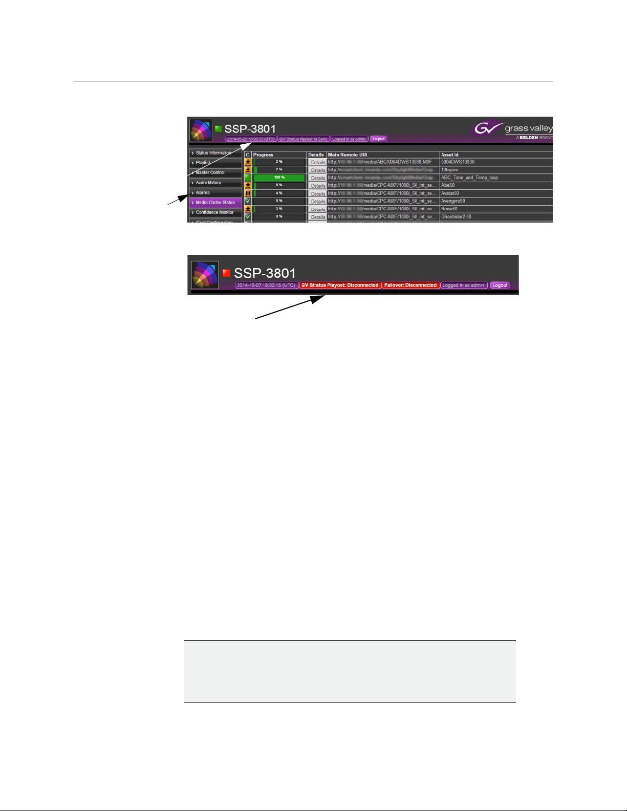
• Page: displays the content for the currently selected Menu item.
Status
header
Menu
Connection
alarms
Fig. 1-1: SSP-3801 Web Interface
Fig. 1-2: Connection alarms displayed in status header
SSP-3801
User Guide
About the SSP-3801 documentation
Your package comes complete with the following documents:
• SSP-3801 Installation and Configuration Guide (PDF: M931-9905-110)
This Guide provides detailed instructions on how to install the SSP-3801 card in a
Densité 3 frame and configure the system parameters using its web interface.
• SSP-3801 User Guide (PDF: M931-9900-110)
This Guide provides detailed instructions on how to access the SSP-3801 web interface,
configure the system preferences, monitor the audio and video output, and use the
timeline to test the playout performance on the card.
While we do our best to ensure that the information is accurate, changes to the software or
hardware can be introduced that don’t always get included in the documentation. If you
notice any errors in the documentation, please contact us at
Opening the web interface
To be able to test, monitor, and diagnose a specific SSP-3801 card, you need to access the
card directly. To do this, you need to access the card on your network using its IP address
and login to it.
IMPORTANT
To access the SSP-3801 web interface, we recommend that you use a
display with a minimum screen resolution of 1920 x 1080 pixels and the
latest version of Google Chrome at 100% zoom in full-screen (F11) mode.
support@miranda.com.
3
Page 8
Overview of the SSP-3801
Login
name
Opening the web interface
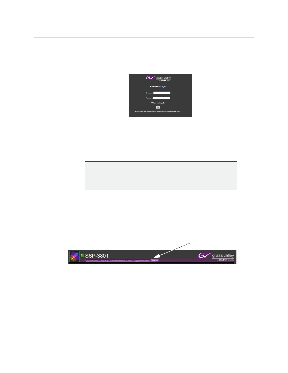
To login to the SSP-3801 card:
1 In a web browser, enter the IP address for the card and press Enter.
For more information on how to assign an IP address for the SSP-3801 card on your
network, see the Installation and Configuration Guide. The SSP-3801 Login page opens.
2 Enter your username and password in their respective fields and click OK.
If this is the first time you are logging into the SSP-3801, you should log in as follows:
Fig. 1-3: SSP-3801 login page
• Username: admin
• Password: P1ayout (the second character is the number 1)
IMPORTANT
If you are configuring the SSP-3801 card for the first time, we recommend
that you change password for the “admin” account.
For more information, see the Installation and Configuration Guide.
If you do not know what your username and password are, contact your System
Administrator.
The System Status information for the SSP-3801 card is displayed in the Status header of
the web interface. It displays the information about the service such as the system time, the
name and status of GV STRATUS Playout, the HCO status (if enabled), and the username of
the person who is currently logged in.
Fig. 1-4: Login name displayed in the header
4
Page 9

Configuring the Channel Options
This chapter explains how to define the Channel Configuration options on the SSP-3801
card, including the locations of the media files, how to manage incoming system
commands, and what actions to take when the media files are not available.
This chapter contains the following sections:
Configuring the off-air behavior . . . . . . . . . . . . . . . . . . . . . . . . . . . . . . . . . . . . . . . . . . . . . . . . . . . . . . . 6
Defining media locations and credentials . . . . . . . . . . . . . . . . . . . . . . . . . . . . . . . . . . . . . . . . . . . . . . 8
Managing the media downloads to the cache . . . . . . . . . . . . . . . . . . . . . . . . . . . . . . . . . . . . . . . . 11
Setting the SCTE-104 access level . . . . . . . . . . . . . . . . . . . . . . . . . . . . . . . . . . . . . . . . . . . . . . . . . . . . . 15
Configuring the General Purpose Input/Output (GPIO) triggers . . . . . . . . . . . . . . . . . . . . . . . . 17
5
Page 10

Configuring the Channel Options
Configuring the off-air behavior
Configuring the off-air behavior
The Off Air Behavior settings define what the card will do if you force the broadcast off air or
something goes wrong during the broadcast such as a loss of media, an empty playlist, a
missing asset, or a hardware or software crash, for example. Whenever you do not have a
primary event on air, it is considered an off-air situation.
IMPORTANT:
When the SSP-3801 card is registered with GV STRATUS Playout, then GV
STRATUS Playout overwrites any Channel Configuration changes made
through the card’s web interface any time it updates the card with its own
changes.
When the card encounters an off-air situation, one of the following occurs:
• If the card was forced off air and no primary events are available in the playlist, the
configured Off Air Action is triggered immediately.
• If no primary event is on air but primary events are available in the playlist, there is a 3
second delay before the configured Off Air Action is triggered. During the first 2
seconds of the delay, the last frame of the last played clip remains on air. This allows
time for the card to resume the playout, if possible. If the card is unable to resume
playout after 2 seconds, it switches to a black screen for 1 second before triggering the
configured Off Air Action.
The Off Air Action can be configured to output a black screen, output a live feed, or output
a full-screen slide that announces that the broadcast is off-air. The Off Air Action can
activate even in the event of a complete hardware or software crash.
If the off-air situation is still not resolved 30 seconds after the Off Air Action was triggered,
the action selected in the Off Air Recovery list is applied. If a primary event is pending such
as a failed event is being restarted, the card will delay triggering the Off Air Recovery for up
to 30 seconds to allow the possibility of a successful resumption of the playout. Once the
Off Air Recovery is triggered, the Off Air Recovery event continues until valid on-air
programming resumes.
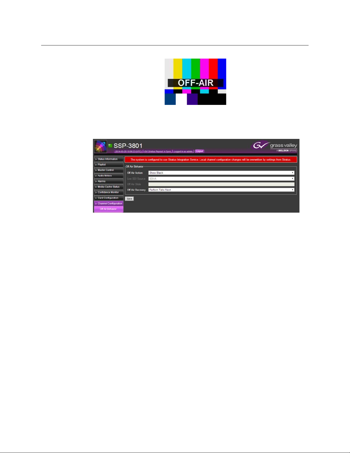
The screen graphic used as the off-air slide should be full-screen, in the required video
standard for the channel, and be in OXT format. The SSP-3801 card contains some samples
of off-air slides in various video standards in the FTP location /mediacache/push, which can
be accessed by using local:// in the path. To use a sample slide, choose the slide with the
appropriate video standard for your channel and type one of the following paths in the Off
Air Slide field:
• local://ApologySlide1080.oxt
• local://ApologySlide720.oxt
• local://ApologySlideNTSC.oxt
• local://ApologySlidePAL.oxt
6
Page 11
SSP-3801
User Guide
Fig. 2-1: Sample of an off-air slide
To configure what action to take when playout is off-air:
1 Select Channel Configuration > Off Air Behavior. The Off Air Behavior page opens.
Fig. 2-2: Off Air Behavior page
2From the Off Air Action list, select one of the following actions to occur after the initial
three seconds has expired and the off-air situation is not resolved:
• Show Black: displays a black screen with no graphics.
• Show Off Air Slide: displays the full-screen graphic specified in the Off Air Slide
field.
• Show Live: displays the live feed from the source selected in the Live SDI Source
list.
3In the Live SDI Source list, select the source for the live feed to be broadcast if an off-air
situation occurs and the Show Live option is selected.
4In the Off Air Slide field, type the URI location for the screen graphic to be broadcast if
an off-air situation occurs and the Show Off Air Slide option is selected. The screen
graphic should be full-screen, in the required video standard for the channel, and be in
OXT format.
5In the Off Air Recovery list, select one of the following actions to occur 30 seconds after
the Off Air Action if the off-air situation is not resolved:
• Stay Off Air: continues the action selected in the Off Air Action list.
• Perform Take Next: places the next scheduled event on-air.
• Play Evergreen Content: places the Evergreen schedule on-air. For more
information about Evergreen, see
About Evergreen content on page 8.
• Play Evergreen Content Unless Playlist is Empty: places the Evergreen schedule
on-air unless the playlist is empty. If the playlist is empty, it defaults to playing the
action selected in the Off Air Action list instead.
6Click Save when done.
7
Page 12
Configuring the Channel Options
About Evergreen content
About Evergreen content
Evergreen content is material that is always relevant. In this case, the Evergreen content is a
library of videos that can be broadcast in place of a previously scheduled event that for
some reason cannot be played. The Evergreen media and schedules are managed by GV
STRATUS Playout; however, the media and schedule are cached on the SSP-3801 card.
The card plays the Evergreen content according to two schedule modes depending on the
situation in the playlist:
• Indefinite Media Scheduling mode: plays a continuous cycle of Evergreen videos
scheduled in the order of the least-played to the most-played. If multiple videos have
the same playout count, those videos will each be selected in a random order until all
with the same playout count are played before continuing to the video with the next
least-played count. This mode is launched when there is an indefinite period to fill with
content such as when the playlist is empty.
• Timed Media Scheduling mode: plays Evergreen videos prioritized by how well the
video fits within the off-air period and its playout count. An off-air situation may occur
when an event in an otherwise valid playlist fails to play. This results in an off-air
situation of a definite duration before another valid primary event is scheduled to play.
To fill the time slot, precedence is given to a single event that fits within the given
period with priority given to events that have not been played in the longest time. If a
match is not found, the off-air period is divided in half and attempts are made to fill the
new time slots. The process repeats until the time slots are less than an hour and no
matches are found. If this occurs, then it reverts to a cycle of videos scheduled in the
order of the least-played to the most-played until the off-air period is filled or exceeded
to ensure continuity of the playout. This mode is launched when there is a gap in the
playlist between valid events.
If the channel is configured to play Evergreen content during an off-air situation, it will
access the local cache and play the Evergreen content as required by the situation.
Defining media locations and credentials
For the SSP-3801 card to access the locations where the media files are stored, you must
specify which servers contain the media. Since these servers are likely to have security, you
must also provide the login information so that the card can access the media files.
IMPORTANT:
When the SSP-3801 card is registered with GV STRATUS Playout, then GV
STRATUS Playout overwrites any Channel Configuration changes made
through the card’s web interface any time it updates the card with its own
changes.
To define the media locations and server credentials:
1 Select Channel Configuration > Media Locations.
8
Page 13
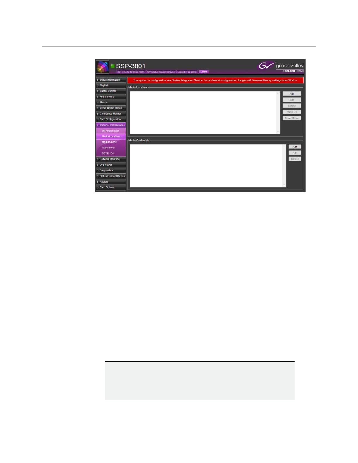
Fig. 2-3: Media Locations/Media Credentials page
SSP-3801
User Guide
2In the Media Locations section, click Add to add new locations where media files are
stored.
3In the Location Details dialog box, type the URI for the media file and click OK. The
format of the URI should be http://[URI], https://[URI], smb://[URI], or ftp://[URI].
4 Define the sequence that the card should follow to download the media. In the Media
Locations section, select the URI and use the Move Up and Move Down buttons to
change its position. Order the media locations closest to the card’s location at the top
of the list and the furthest to the bottom.
5In the Media Credentials section, click Add to add the login credentials for a media
server.
6In the Credential Details dialog box, type the required information in the following
fields to enable access to the server that contains the media files:
• URI: type the http path where the media files reside.
• Domain: type the name of the domain that stores the media files.
• Username: type the login name for the specified Domain.
• Password: type the password assigned to this Username.
Editing media locations
IMPORTANT:
When the SSP-3801 card is registered with GV STRATUS Playout, then GV
STRATUS Playout overwrites any Channel Configuration changes made
through the card’s web interface any time it updates the card with its own
changes.
9
Page 14
Configuring the Channel Options
Deleting media locations
To edit a m edi a loca t i on:
1 Select Channel Configuration > Media Locations.
2In the Media Locations section, select the location and click Edit.
3In the Location Details dialog box, change the URI address.
4Click OK.
Deleting media locations
IMPORTANT:
When the SSP-3801 card is registered with GV STRATUS Playout, then GV
STRATUS Playout overwrites any Channel Configuration changes made
through the card’s web interface any time it updates the card with its own
changes.
To delete a media location:
1 Select Channel Configuration > Media Locations.
2In the Media Locations section, select the location that you want to delete.
3Click Delete. The media location is removed from the list; however, this does not delete
the media file itself from its location.
Editing media credentials
IMPORTANT:
When the SSP-3801 card is registered with GV STRATUS Playout, then GV
STRATUS Playout overwrites any Channel Configuration changes made
through the card’s web interface any time it updates the card with its own
changes.
To edit a media credential:
1 Select Channel Configuration > Media Locations.
2In the Media Credentials section, select the credential and click Edit.
3In the Credential Details dialog box, change the credential settings.
4Click OK.
Deleting media credentials
IMPORTANT:
When the SSP-3801 card is registered with GV STRATUS Playout, then GV
STRATUS Playout overwrites any Channel Configuration changes made
through the card’s web interface any time it updates the card with its own
changes.
10
To delete a media credential:
1 Select Channel Configuration > Media Locations.
2In the Media Credentials section, select the credential you want to delete.
Page 15
3Click Delete.
Managing the media downloads to the cache
The SSP-3801 card features onboard storage space that allows you to store and preload
media content locally so that it can be retrieved and broadcast smoothly and quickly. You
can define how the card manages the media cache and what action it should take if the
server times out and the media cannot be accessed.
IMPORTANT:
When the SSP-3801 card is registered with GV STRATUS Playout, then GV
STRATUS Playout overwrites any Channel Configuration changes made
through the card’s web interface any time it updates the card with its own
changes.
To configure how the media cache is managed:
1 Select Channel Configuration > Media Cache. The Media Cache page opens.
SSP-3801
User Guide
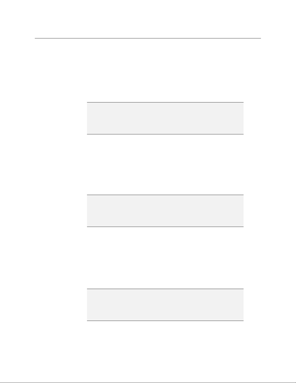
Fig. 2-4: Media Cache page
2In the Channel Media section, define when the indicated pre-broadcast alarms are
triggered (in HH:MM format).
• Missing Media time window: type the amount of time before broadcast to trigger
the Missing Media alarm if the media file cannot be found.
• Inaccessible Media time window: type the amount of time before broadcast to
trigger the Inaccessible Media alarm if the media file was found, but cannot be
downloaded to the SSP-3801’s storage space.
3In the Transfer Speed Alarm section, define
• Minimal Download Speed: type the minimum acceptable download speed (from 1
to 100MB/s) for the media. An alarm is triggered if the download speed falls below
the specified threshold.
• Speed Test Period: type the number of seconds (from 1 to 120) defining the length
of the test period used to verify the actual download speed. The download speeds
are tested throughout the specified duration and are averaged. The resulting value
is compared to the Minimal Download Speed threshold to verify its performance.
4In the Max segments per download field, type the maximum number of blocks (up to
10) you can download per server at a time.
11
Page 16

Configuring the Channel Options
Manually uploading media files into the cache via FTP
5The Parallel Download Configuration section defines the maximum boundaries for
downloads performed in parallel. Set the following values:
• Max (overall) parallel downloads: type the maximum number of downloads (up to
10) that can take place simultaneously.
• Max SMB parallel downloads: type the maximum number of downloads (up to 4)
that use the Server Message Block (SMB) protocol.
• Max HTTP/HTTPS/FTP parallel downloads: type the maximum number of
downloads (up to 10) that can take place simultaneously using the HTTP, HTTPS or
FTP protocol.
6Click Save when done.
Manually uploading media files into the cache via FTP
Media files are transferred to the card in two ways: automatically from GV STRATUS Playout
or manually using FTP. The storage space is shared between the two methods, but it is not
managed in the same way. The media downloaded from GV STRATUS Playout is managed
by the card so that the media scheduled closest to air is cached first and media files not
immediately required may be deleted to make room for those that are. The media files that
were manually uploaded on the card are not managed by the card and remain until
manually deleted, which can be useful for more ‘permanent’ media such as station logos.
Be judicious about the amount of media that you manually upload on the card. Since both
methods share the storage space, the more media manually uploaded on the card, the less
room remains for GV STRATUS Playout’s cache of media.
The manually uploaded media files are also only available on the card and are not made
available to other cards. Unlike the media downloaded from GV STRATUS Playout, the
manually uploaded media files are not managed through the GV STRATUS Playout service
and therefore will not be restored automatically after a card hot swap.
Media files that are manually downloaded to the cache can be accessed by using local:// in
the path. For example, if you downloaded a file called TestSlide.oxt into the
/mediacache/push folder, you would type local://TestSlide.oxt to select the file.
To download media to the cache:
1 Configure the FTP access in the card:
•In the left pane, click Card Configuration > Security.
•In the FTP Password field, type a password for the FTP server.
•In the Device Access Settings section, select Enabled for FTP Access.
•Click Save.
2 Open an FTP connection with the card using “ftp” as the username and the password
that you set in Card Configuration > Security.
3 Add the media files to the mediacache/push folder.
12
Page 17

About the supported characters for asset IDs, paths, and mnemonics
The SSP-3801 card only supports ASCII 7-bit printable characters for router source and
destination mnemonics, the asset IDs for the media files, and the components of the path
to the media files. The list of supported characters:
Symbol Hexadecimal Description
20 space
! 21 exclamation mark
" 22 double quote
# 23 number sign
$ 24 dollar sign
% 25 percent
& 26 ampersand
' 27 single quote
( 28 left or opening parenthesis
SSP-3801
User Guide
) 29 right or closing parenthesis
* 2A asterisk
+ 2B plus
, 2C comma
- 2D minus or dash
. 2E dot or period
/ 2F forward slash
0 30 zero
1 31 one
2 32 two
3 33 three
4 34 four
5 35 five
6 36 six
7 37 seven
8 38 eight
9 39 nine
: 3A colon
; 3B semi-colon
< 3C less than
= 3D equal sign
13
Page 18

Configuring the Channel Options
About the supported characters for asset IDs, paths, and mnemonics
Symbol Hexadecimal Description
> 3E greater than
? 3F question mark
@ 40 at symbol
A 41 uppercase A
B 42 uppercase B
C 43 uppercase C
D 44 uppercase D
E 45 uppercase E
F 46 uppercase F
G 47 uppercase G
H 48 uppercase H
I 49 uppercase I
J 4A uppercase J
K 4B uppercase K
L 4C uppercase L
M 4D uppercase M
N 4E uppercase N
O 4F uppercase O
P 50 uppercase P
Q 51 uppercase Q
R 52 uppercase R
S 53 uppercase S
T 54 uppercase T
U 55 uppercase U
V 56 uppercase V
W 57 uppercase W
X 58 uppercase X
Y 59 uppercase Y
Z 5A uppercase Z
[ 5B left or opening bracket
\ 5C backslash
] 5D right or closing bracket
^ 5E caret or circumflex
_ 5F underscore
14
` 60 grave accent
Page 19

Symbol Hexadecimal Description
a 61 lowercase a
b 62 lowercase b
c 63 lowercase c
d 64 lowercase d
e 65 lowercase e
f 66 lowercase f
g 67 lowercase g
h 68 lowercase h
i 69 lowercase i
j 6A lowercase j
k 6B lowercase k
l 6C lowercase l
m 6D lowercase m
n 6E lowercase n
o 6F lowercase o
SSP-3801
User Guide
p 70 lowercase p
q 71 lowercase q
r 72 lowercase r
s 73 lowercase s
t 74 lowercase t
u 75 lowercase u
v 76 lowercase v
w 77 lowercase w
x 78 lowercase x
y 79 lowercase y
z 7A lowercase z
{ 7B left or opening brace
| 7C vertical bar or pipe
} 7D right or closing brace
~ 7E equivalency sign or tilde
Setting the SCTE-104 access level
The SCTE-104 standard allows you to receive trigger messages from the audio or video
feed, which can be used to flag the start and end points for commercial breaks, for example.
It allows you to receive trigger messages in the SDI (Serial Digital Interface) signal that you
can use to control the playlist.
15
Page 20
Configuring the Channel Options
Setting the SCTE-104 access level
The SSP-3801 card supports SCTE-104 splice requests with the following
splice_insert_types:
• spliceStart_normal: determines the pre-roll period in milliseconds, which defines the
delay between receiving the message and putting the event on air.
• splice_cancel: cancels a scheduled Take Next initiated by a spliceStart_normal
command.
• spliceStart_immediate: attempts to take the next event to air as quickly as possible
(non-deterministic).
In all cases, the event that is to be taken to air should already be on hold in a cued or
commit state. Typically, the schedule should contain an SCTE-104 triggerable manual event
that will hold at the on-air threshold until one of the SCTE-104 splice request is received. For
more information on SCTE-104, refer to the “SCTE 104 2014 Automation System to
Compression System Communications Applications Program Interface (API)” available from
http://www.scte.org.
IMPORTANT:
When the SSP-3801 card is registered with GV STRATUS Playout, then GV
STRATUS Playout overwrites any Channel Configuration changes made
through the card’s web interface any time it updates the card with its own
changes.
To configure how the SSP-3801 card will treat SCTE-104 messages:
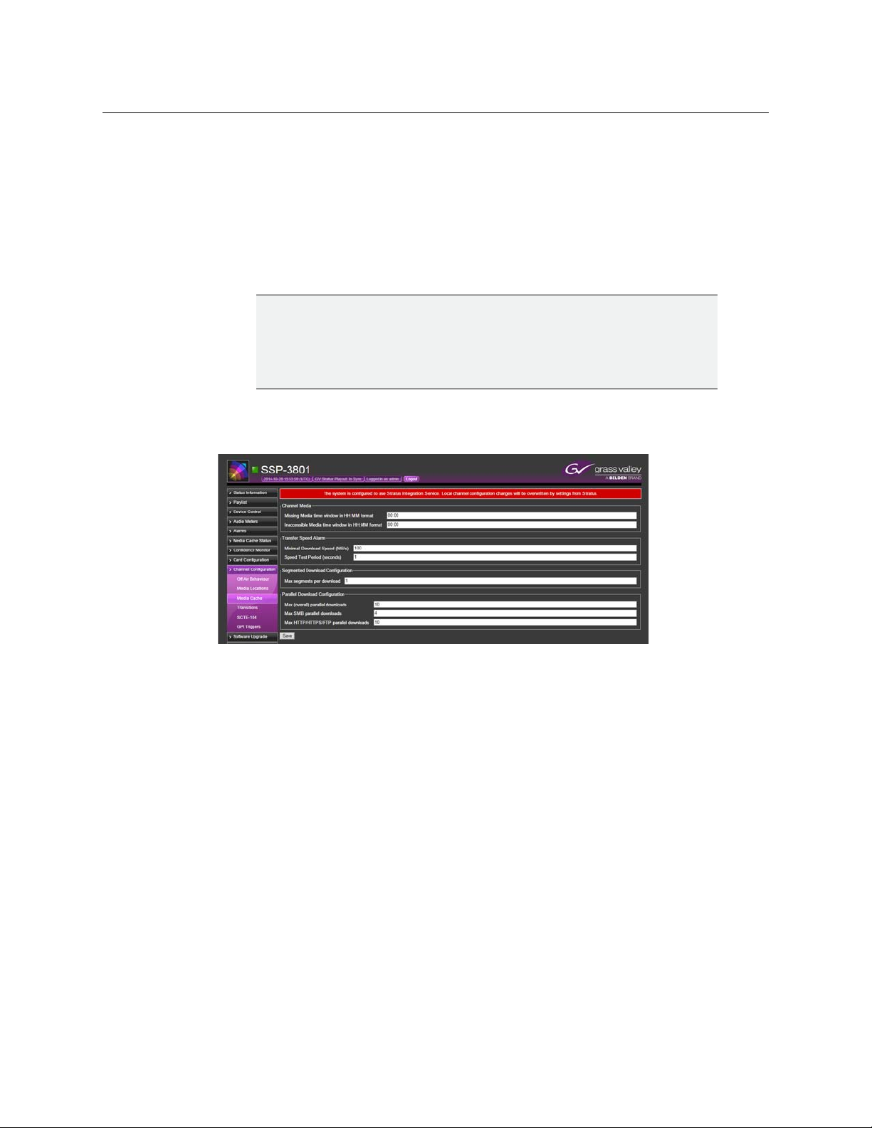
1 Select Channel Configuration > SCTE-104. The SCTE-104 Access page opens.
Fig. 2-5: SCTE-104 page
2 Select the Act upon SCTE-104 splice request triggers checkbox to execute and log
received SCTE-104 splice messages. Clear the checkbox to ignore and not log the splice
messages.
3 Select the Block all SCTE-104 messages from being passed-through checkbox to
prevent all SCTE-104 messages from reaching the card and from being logged. Clear
the checkbox to allow SCTE-104 messages to reach the card.
4Click Save when done.
16
Page 21
SSP-3801
User Guide
Configuring the General Purpose Input/Output (GPIO) triggers
The SSP-3801 card has two General Purpose Input/Output (GPIO) connectors offering up to
four opto-isolated, open collector GPIOs. The pinouts are 1|G|2 and 3|G|4. The GPIO pins
function both as inputs and outputs. As inputs they can be used to trigger internal preprogrammed actions and as outputs they can be used to trigger downstream external
hardware. It is not recommended to use the GPIO pins as both inputs and outputs
simultaneously.
When used as an output, the GPIO operates as follows:
• ON: the GPIO pin is internally driven to ground by an opto-isolated, open collector
transistor (active low is represented by 1V or less) and can sink up to 20mA.
• OFF: the GPIO pin is internally pulled weakly high.
When used as an input, the GPIO input is activated as follows:
• ON: the GPIO pin is connected to 0V.
• OFF: the GPIO pin is not connected (the GPIO signal pin is pulled high).
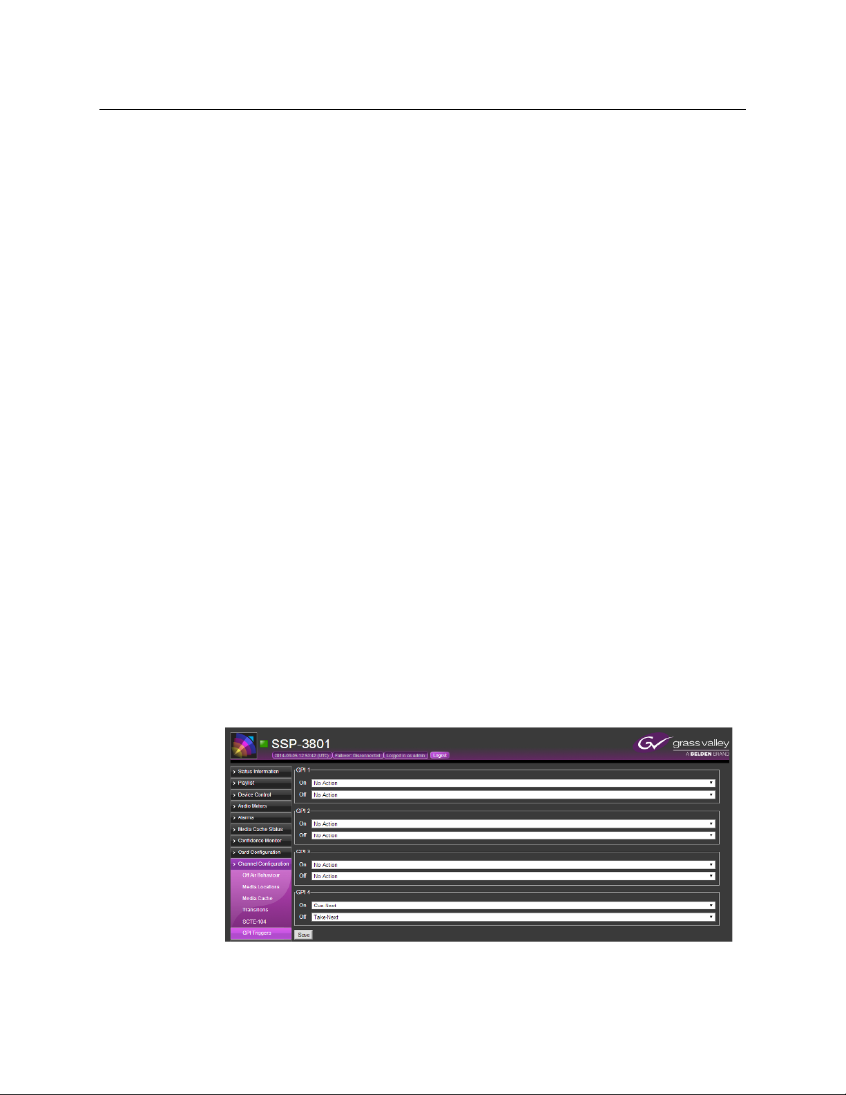
A change from one state to another when the pin is used as an input can be configured to
trigger an action in the playlist. On the GPI Triggers page, you can configure the SSP-3801
card to perform one of the following actions when an input changes to an On or Off state:
• No Action: a change to the state is not acted upon.
• Take Next: a change to the state triggers a Take Next action, which places the next
event in the playlist on air.
• Cue Next: a change to the state triggers a Cue Next action, which cues the next primary
event, its related secondary events, and any subsequent automatic events so they are
ready to go on air safely when a Take Next action is performed.
• Hold Next: a change to the state triggers a Hold Next action, which prevents the next
events from going on-air.
• Drop Next: a change to the state triggers a Drop Next action, which removes the next
event in the playlist.
To configure the GPI triggers:
1 Select Channel Configuration > GPI Triggers. The GPI Triggers page opens.
Fig. 2-6: GPI Triggers page
17
Page 22

Configuring the Channel Options
Configuring the General Purpose Input/Output (GPIO) triggers
2 In each GPI section, specify the action for each state. Each GPI section represents one
input.
18
Page 23

Testing and Troubleshooting the Playout
This chapter explains how to use the Playlist page to test or troubleshoot the playout from
the card. The Playlist page is not intended to be used to create or edit schedules. Schedules
are created, edited, and added to playlists in GV STRATUS Playout and then the playlist is
downloaded to the SSP-3801 card.
Instead, the Playlist page is used to diagnose whether an issue is caused by GV STRATUS
Playout or the card, to administer the playout during the loss of connectivity with GV
STRATUS Playout, or to test or troubleshoot the configuration of the card.
This chapter contains the following sections:
About the Playlist page . . . . . . . . . . . . . . . . . . . . . . . . . . . . . . . . . . . . . . . . . . . . . . . . . . . . . . . . . . . . . . . 20
Troubleshooting failures in the playout . . . . . . . . . . . . . . . . . . . . . . . . . . . . . . . . . . . . . . . . . . . . . . . 23
Controlling the playout of events . . . . . . . . . . . . . . . . . . . . . . . . . . . . . . . . . . . . . . . . . . . . . . . . . . . . . 24
Manually breaking away to a live event . . . . . . . . . . . . . . . . . . . . . . . . . . . . . . . . . . . . . . . . . . . . . . . 26
Manually enabling or disabling secondary events in the playout . . . . . . . . . . . . . . . . . . . . . . 28
Configuring the transitions for the Live and Manual Controls . . . . . . . . . . . . . . . . . . . . . . . . . . 29
Creating a test playlist . . . . . . . . . . . . . . . . . . . . . . . . . . . . . . . . . . . . . . . . . . . . . . . . . . . . . . . . . . . . . . . . 32
Deleting an event from the playlist . . . . . . . . . . . . . . . . . . . . . . . . . . . . . . . . . . . . . . . . . . . . . . . . . . . 42
Deleting all the events from the playlist . . . . . . . . . . . . . . . . . . . . . . . . . . . . . . . . . . . . . . . . . . . . . . . 43
19
Page 24
Testing and Troubleshooting the Playout
Timeline
Boundary
On-air
Cued
About the Playlist page
About the Playlist page
The SSP-3801 web interface features a timeline that displays the status of the events as the
playlist is played out. Since the playlist is created and managed by GV STRATUS Playout and
then downloaded into the SSP-3801 card, GV STRATUS Playout overwrites any playlist
changes made in the Playlist page any time it updates the card with its own changes.
Fig. 3-1: Playlist page
A timeline appears at the top of the Playlist page. It is a visual display of the playlist as it is
broadcast. It contains three threshold markers:
• Cued (orange, far-right): indicates that the media event is ready to be played. The time
between the Cued and On-air markers is 15 seconds.
• On-air (red, middle): indicates that the media event is currently being played. The time
between the On-air and Timeline boundary markers is 10 seconds.
• Timeline boundary (grey, far-left): indicates the boundary of the timeline view. Once
an event moves fully past the boundary, it disappears from the timeline.
Events become off-air as soon as the entirety of the event rectangle has moved past the Onair threshold (red line). The event remains visible in the timeline until it moves past the
Timeline boundary (grey line).
Fig. 3-2: Playlist timeline
You can move left and right through the timeline to view the entire playlist by clicking in
the timeline and dragging your cursor left or right. To increase or decrease the period
visible in the timeline, click in the timeline and use your scroll button to zoom in or out of
the timeline.
As an event moves through the timeline from right to left, it changes color to indicate its
status. As the events playout, their status is displayed in the timeline, in the channel grid at
the bottom of the page, and in the buttons on the Manual Controls toolbar.
20
Page 25

Status color Description
Red
Dark Orange
The event cannot be broadcast for reasons such as the event is not yet
available from the cache or the event was not found. It can also mean that
the event ended earlier than its allocated duration.
The event is cueing up.
SSP-3801
User Guide
Orange
Purple
Dark green
Green
White/Grey
The event is cued up and ready to be played.
The event is not on-air due to a Breakaway event, is unable to resume playing
after the breakaway event ends, or has been manually disabled from the
playout.
The event is about to go on air.
The event is being broadcast.
The event is not active.
The Playlist page also includes various toolbars you can use to make changes in the playlist:
• Playlist Controls: located on the bottom left of the timeline, it contains controls such as
Hold Next and Take Next, for example. The controls allow you to manually change
when events are placed on-air.
• Live Controls: located on the bottom right of the timeline, it contains controls such as
Breakaway-A, for example. The controls allow you to manually interrupt the playlist to
broadcast a live event.
• Manual Controls: located under the Playlist Controls and Live Controls toolbars, it
contains controls that allow you to enable or disable secondary events in the playout.
• Playlist Editing Controls toolbar: located under the Manual Controls toolbar, it contains
controls that allow you to manually append events to the playlist or sync with GV
STRATUS Playout. This toolbar is hidden by default.
Between the Cued and On-air threshold markers is a 15-second period referred to as the
pre-roll window in which the event is prepared to go on air. During the pre-roll, you can
edit, insert, replace, drop, undrop, and delete events, but events cannot be uncued using
the Uncue Last button. All properties of the event can be edited, except the event’s Time
mode and Date/Time. Be prudent when making changes at this stage. When an event is
changed in the pre-roll window, it must go through the process of being prepared to go on
air again so this action should not be performed too close to the On-air threshold or
unwanted consequences may occur.
At the very bottom of the Playlist page is the channel grid. It provides details about the
events in the playlist and displays the status of the events as they move through the
timeline:
Status Description
Accessible The media file is accessible, but has not been cached.
Breakaway The event is being interrupted by a live feed.
Caching The caching process has started, but a progress report is not available yet.
Caching (%) The caching process is in progress and is reporting a percent (%) value of
completion.
21
Page 26

Testing and Troubleshooting the Playout
Changing how event types appear in the timeline
Status Description
Commit The event is committed to playout (occurs just before playout begins).
Cued The event has been cued.
Cueing The event is being cued.
Done The event successfully played out for its entire duration. Its on air time may
differ from the scheduled duration if an action such as Take Next or Join in
Progress (see “JIP” in GV STRATUS Playout Operator Guide) was used;
however, it is marked Done since the event played for the entirety of its
reported on air time.
Dropped The event is set as dropped from the playlist. It no longer appears in the
timeline, but remains visible in the channel grid.
Evergreen The event was unable to play and is being replaced by Evergreen content.
Failed The event failed to play.
Inaccessible The location for the media file is not accessible.
Manual off The secondary event was manually disabled from the playout. This occurs
when a secondary event is taken off air by clicking a Manual Control on the
Playlist page.
Missing The media file is missing from the defined location.
Not Ready The event is not ready for playout.
Off Air The event is not playing.
On Air The event is on air.
Partial The event only played out a portion of its duration. It may not have played
out entirely due to a user requested breakaway, a bad or truncated piece of
media, system misconfiguration or a fault in the playback system.
Ready The event is ready for playout.
Skipped The event was skipped in the playout. An event can become skipped when a
dropped event enters the pre-roll window or when a playlist is appended
with events that are in the past. Skipped events do not appear in the
timeline, but remain visible in the channel grid.
Standby The primary media file was unable to play and has been replaced by the
configured standby media file.
Suppressed The event is suppressed from playing in the playout.
Un-dropped The event was dropped, but has been un-dropped from the playlist.
Waiting The media file is in an initial state waiting for checks to be performed.
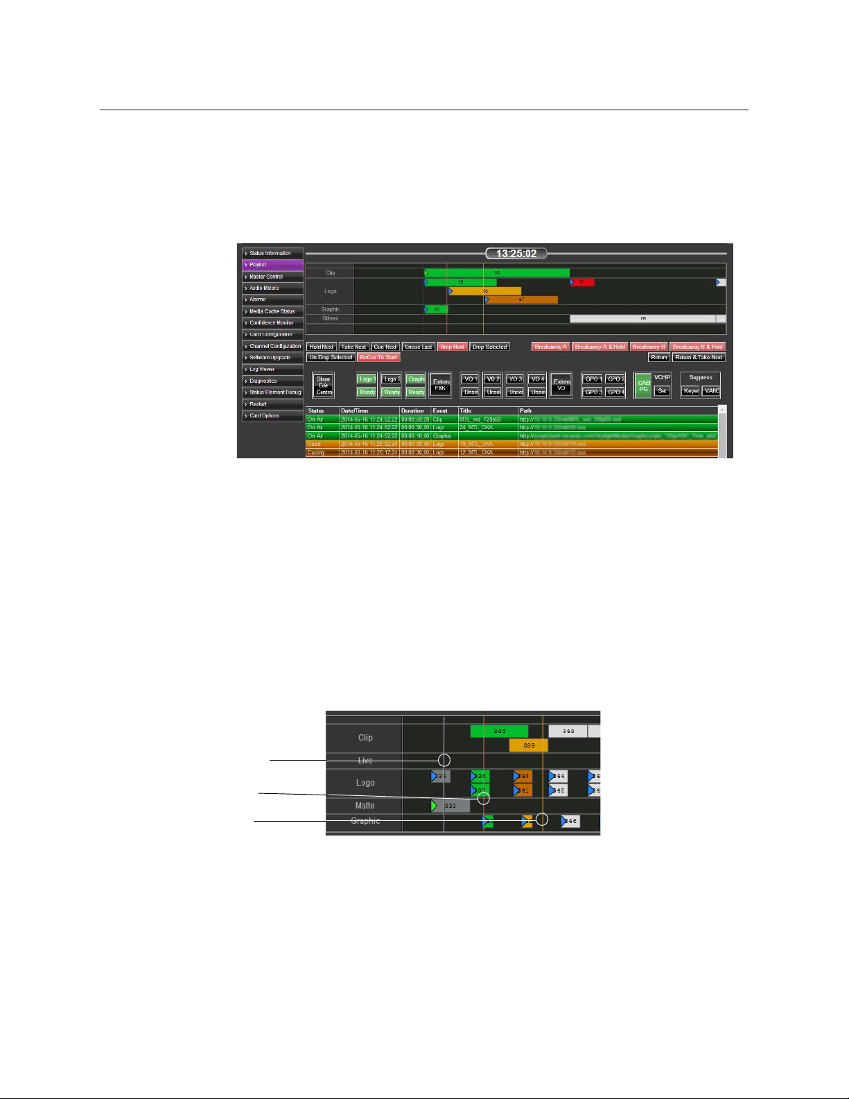
Changing how event types appear in the timeline
When events appear on the timeline, they are divided into rows according to their type. You
can choose which types appear as timeline elements. If the playlist contains types that you
have chosen not to display, they are regrouped into a row labeled Others.
22
Page 27

SSP-3801
User Guide
Fig. 3-3: Example of elements in the timeline
To choose the timeline elements:
1 Select Card Configuration > Playlist Elements. The Playlist Timeline Elements page
opens.
Fig. 3-4: The Playlist Timeline Elements page
2 To add an element, click Add, select the element in the Type list, and click OK.
3 To delete an element from the list, select the element and click Delete.
4 To change order in which the elements are displayed in the list, select the element and
click Move Up to move it higher in the list or Move Down to move it lower.
5 To reset the order of the playlist elements, click Reset. The display is restored to its
factory settings.
Troubleshooting failures in the playout
The main causes of a playout failure are the result of an issue with a media file, a frame rate
mismatch, or a system or software fault.
Issues with media files can sometimes be identified before playout. When a playlist is added
to a channel, the card performs some basic checks on the scheduled events. As the events
are verified, their status should change to Ready. If the status changes to Missing or
Inaccessible, the media file associated to the event cannot be found. This can be caused by
an invalid path to the media file or an asset not being registered with the GV STRATUS
Playout service.
Under normal circumstances, a clip should cue in less than a few seconds, but may take up
to 15 seconds depending on its file size, structure (indexing), and bit rate. If it takes longer,
then there may be a problem with the media file.
23
Page 28

Testing and Troubleshooting the Playout
Controlling the playout of events
The following are some common playout failures detected by the card and their causes:
Failure Symptom Causes
Clip content runs out Playout stops and does not
Clip stops prematurely Playout stops and does not
Playout momentarily
stops and restarts
recover
recover
Playout stops momentarily
and then joins in progress (off
air behavior may be expected)
• The event is longer than the clip
duration
• The clip is corrupted
• The clip is in the process of being
ca ch ed as i t g oes o n a ir, but is not
downloading fast enough to be
played out
• The MPEG essence inside the
MXF file is corrupt
• The frame rate for the clip does
not match the frame rate for the
output standard
• The frame rate for the clip does
not match the frame rate for the
output standard
• A fault occurs in the MXF
demuxer as a result of an oddity
or corruption in the file
• A unexpected software fault
occurs that prevents the MPEG
decoders from obtaining the
data
Playout completely stops
(unrecoverable)
Playout stops, does not
recover and becomes
unresponsive to future events
In these situations, the configured off-air behavior is triggered when the playout stops. In
some cases, the card may be able to recover on its own. Depending on the cause, you can
do one of the following to resolve the issue:
• Verify and adjust the duration of the event in the schedule
• Verify the frame rate of the clip and the channel
• Replace the damaged media file
• Modify the media file so its file size, structure, or bit rate are optimized for playout
• Generate a diagnostics archive and reboot the card if it becomes unresponsive
Controlling the playout of events
The playlist is normally created and managed from GV STRATUS Playout. However, the
Playlist page contains a toolbar of controls, called Playlist Controls, that allows you to make
changes in the playlist.
IMPORTANT: During the playout, some buttons may turn red. Red
buttons indicate controls that should be used with caution as they
may adversely affect the playout if not used correctly.
• A system fault has occurred
24
To control the playout:
1 From the menu, click Playlist. The Playlist page opens.
Page 29

SSP-3801
User Guide
2 Use the following Playlist Controls as required:
Control Description Next Actions
Hold Next Prevents the next events from going on-air.
The event currently on-air continues to play past its
duration. Depending on the type of event on-air,
the timeline reflects the increased duration of the
event or the playlist falls into an off-air situation
Take N e x t
until the
Note: If a fixed event follows the event on hold, the
fixed event and its related events will still go on air at
the fixed time and thus canceling the hold. For more
information on fixed events, see
of automatic and fixed primary events on page 36.
Places the next event on-air immediately.
The event must be in a Cued state before you can
place it on-air.
Take N ext button is clicked.
About the behavior
Cue Next Cues one or more events to allow the next
primary event, its related secondary events, and
any subsequent automatic events to go on air
safely when Take N ex t is clicked.
For more information on automatic events, see
About the behavior of automatic and fixed primary
events on page 36.
Uncue Last
Drop Next
Drop Selected
Places the last event cued back into a ready state.
Uncueing the event allows it to be edited. If the
event has reached the pre-roll window, it cannot be
uncued. The pre-roll window is a 15-second period
before the On-air threshold marker in which the
event is prepared to go on air.
Removes the next event in the schedule.
If the event remains dropped at the moment is was
to go on-air, it appears as skipped in the channel
grid to confirm it was not played.
Removes the event selected in the channel grid at
the bottom of the page from the playlist.
The event is removed from the timeline, but still
appears in the channel grid labeled as dropped. If
the event remains dropped at the moment is was to
go on-air, it appears as skipped in the channel grid
to confirm it was not played.
Cue Next
Tak e Next
Cue Next
Tak e Next
none
none
none
25
Page 30

Testing and Troubleshooting the Playout
Manually breaking away to a live event
Control Description Next Actions
Un-Drop Selected
Recue
Replaces the dropped event back into its place in
the playlist.
This control can be used when you have a choice of
several events for a time slot, but are unsure which
should be placed in the playlist. The events can be
left in a dropped state until decision is made and
the chosen event can be un-dropped.
Takes the event off-air and places it on hold at the
On-air threshold. The previous event is replaced on
air in progress until the Take Next button is clicked.
This is usually only used in the case that an event
was accidentally placed on-air too early.
Manually breaking away to a live event
The playlist is normally created and managed from GV STRATUS Playout. However, the
Playlist page contains a toolbar of controls, called Live Controls, that allows you to interrupt
the playlist with a live event.
IMPORTANT: During the playout, some buttons may turn red. Red
buttons indicate controls that should be used with caution as they
may adversely affect the playout if not used correctly.
none
Tak e Next
To interrupt the playlist with a live feed:
1 From the menu, click Playlist. The Playlist page opens.
2 Use the following Live Controls as required:
Control Description Next action
Breakaway-A
Switches the playout from the playlist to the live
feed incoming from the SDI A port. The scheduled
event continues to play off-screen while the live
feed is broadcast.
To stop broadcasting the live feed, you can click
Return or
Return & Take Next
Return or Return & Take Next.
Breakaway-A &
Hold
Switches the playout from the playlist to the live
feed incoming from the SDI A port and places the
on-air event on hold.
To stop broadcasting the live feed, you must click
Return & Take Next
Return & Take Next.
Note: If you click Return, the screen will go black. If
the next event has not been placed on air after two
seconds, the off-air behavior is triggered.
26
Page 31

Control Description Next action
SSP-3801
User Guide
Breakaway-B
Breakaway-B &
Hold
Breakaway
Source
Breakaway
Switches the playout from the playlist to the live
feed incoming from the SDI B port. The scheduled
event continues to play off-screen while the live
feed is broadcast.
To stop broadcasting the live feed, you can click
Return or Return & Take Next.
Switches the playout from the playlist to the live
feed incoming from the SDI B port and places the
on-air event on hold.
To stop broadcasting the live feed, you must click
Return & Take Next.
Note: If you click Return, the screen will go black. If
the next event has not been placed on air after two
seconds, the off-air behavior is triggered.
Determines the router source from which to stream
the live feed when the breakaway event is triggered.
To select the router source:
1Click the Breakaway Source button.
2Click Refresh to obtain a list of the available
router sources.
3 Click the desired router source and click
Select. To filter the list, type the name of the
router source in the Search field. To order the
list, click the arrows in the column headers.
Note: If the page is reloaded, the Breakaway
Source will revert to its default, which is set in
Channel Configuration > Transitions.
This feature is displayed only when an external
router is configured. For more information, see
Configuring an external router for switching
between live events on page 40 in the SSP-3801
Installation and Configuration Guide.
Switches the playout from the playlist to the
specified router source to stream the live feed
supplied via a router connected to both the SDI A
and SDI B inputs on the card's rear panel. The
scheduled event continues to play off-screen while
the live feed is broadcast. This feature is displayed
only when an external router is configured.
To stop broadcasting the live feed, you can click
Return or Return & Take Next.
Return or
Return & Take Next
Return & Take Next
Breakaway or
Breakaway & Hold
Return or
Return & Take Next
27
Page 32

Testing and Troubleshooting the Playout
Manually enabling or disabling secondary events in the playout
Control Description Next action
Breakaway &
Hold
Switches the playout from the playlist to the
specified router source to stream the live feed
supplied via a router connected to both the SDI A
and SDI B inputs on the card's rear panel and places
the on-air event on hold. This feature is displayed
only when an external router is configured.
To stop broadcasting the live feed, you must click
Return & Take Next
Return & Take Next.
Return
Return & Take
Next
Resumes the playout of the playlist at the point it
would have been if the live feed had not interrupted
the playout.
Starts the playout of the event from the moment it
was stopped to stream the live feed. It plays as if the
event was paused while the live feed was broadcast.
none
none
Manually enabling or disabling secondary events in the playout
The playlist is normally created and managed from GV STRATUS Playout. However, the
Playlist page contains a toolbar of controls, called Manual Controls, that allows you to
manually enable or disable secondary events in the playout. These manual events do not
appear in the timeline view or in the channel grid on the Playlist page when they are
triggered. They are user-driven events that operate in parallel with playlist events.
Control Description
Logo
Graphic
Voiceover ( VO)
External F&K The External F&K (Fill&Key) and External VO buttons place the media
GPO The GPO buttons trigger the external hardware downstream connected to
VCHIP
The Logo, Graphic, and Voiceover (VO) buttons are each paired with a status
button which switches between Unset and Ready depending on its
availability. The event associated to the control must be available, and
therefore in a Ready state, before it can be placed on air. When the Logo,
Graphic or VO button is green, it is present in the playout.
available from their respective ports on air when enabled. When their
buttons are green, their corresponding events are present in the playout.
the GPIO connectors when enabled. When their buttons are green, they are
being triggered.
The VCHIP section contains two buttons. The Set button is used to select
the content advisory setting. The other button displays the currently set
rating system and rating. When the rating button is green, the rating is
present in the playout.
28
Page 33

SSP-3801
User Guide
Control Description
Keyers The Keyers button in the Suppress section is used to hide the Graphic, Logo,
and Fill&Key events from the playout. When the button is green, the event is
hidden.
VAN C The VANC button in the Suppress section is used to control whether or not
the Vertical Ancillary Data Space (VANC) files are being embedded in the
playout. When the button is green, the VANC files such as SCTE-104 triggers
are disabled.
To manually control the secondary events:
1 From the menu, click Playlist. The Playlist page opens.
2 Use the Manual Controls as required:
• If the button is green, click to disable it.
• If the button is grey, click to enable it.
To select a media event for a button in an Unset state:
1 Click the control’s corresponding Unset button.
2In the Search for field, choose Asset to view the media events downloaded from GV
STRATUS Playout that are still present in the cache or File to view the media events
stored on the card.
3In the Filter field, type part of the media file that you are searching for to display only
the files containing those characters in their filename.
Note: The card only supports ASCII 7-bit printable characters for
mnemonics, the asset IDs, and paths. For more information, see
About
the supported characters for asset IDs, paths, and mnemonics on
page 13.
4 Select the media event.
5Click Choose.
Configuring the transitions for the Live and Manual Controls
The settings on the Transitions page determine how a logo, graphic, voiceover, or
breakaway event transitions on or off screen when they are manually controlled using the
buttons on the Live Controls or Manual Controls toolbars.
To configure the transitions:
1 Select Channel Configuration > Transitions. The Trans itions page opens.
29
Page 34

Testing and Troubleshooting the Playout
Configuring the transitions for the Live and Manual Controls
Fig. 3-5: Transitions page
2In the Breakaway Transition section, configure how the Breakaway events (initiated
using the breakaway buttons on the Playlist page) are handled:
Field Description
Breakaway
Tra nsitio n
Select the type of scene change affect to apply to the beginning of this
event. You have the following choices:
• Cut: it switches from one event to another instantly
• Mix: creates a cross-fade between the two events where the
incoming event merges and replaces the outgoing event
• Cut and Fade: the outgoing event switches to black and the
incoming event fades in.
• Fade and Cut: the outgoing event fades to black and the incoming
event appears instantly.
• Fade and Fade: the outgoing event fades to black and the
incoming event fades in (V-Fade).
30
Page 35

Field Description
Duration
Type the total amount of time allocated for the transition to complete.
Note: Illegal drop-frame timecodes are automatically rounded up to the
nearest drop-frame timecode value; for example, 00:01:00;00 would be
round up to 00:01:00;02.
SSP-3801
User Guide
Default
Router Source
Select the default router source used to stream the live feed supplied via
a router connected to the card when a breakaway event is initiated.
To select the router source:
1Click the Select button.
2Click Refresh to obtain a list of the available router sources.
3 Click the desired router source and click Select. To filter the list,
type the name of the router source in the Search field. To order
the list, click the arrows in the column headers.
This feature is available only when an external router is configured. For
more information, see
between live events on page 40 in the SSP-3801 Installation and
Configuration Guide.
Configuring an external router for switching
4In the Manual Voiceover Transition section, configure how the manually controlled
voiceover events (VO 1, VO 2, VO 3, VO 4, and External VO buttons) are handled:
Field Description
Fade in
Fade out
Duck
Type the time period over which the volume of the voiceover event is
raised to 100% when the event is activated.
Type the time period over which the volume of the voiceover event is
lowered to 0% when the event is deactivated.
Type how much to reduce the level of the background audio (in
decibels).
Preset
Type how much to increase the level of the foreground audio (in
decibels).
5In the Manual Graphic Transition, configure how the manually controlled graphic
events (Graphic and External F&K buttons) are handled:
Field Description
Fade in
Fade out
Duck
Preset
Opacity (%)
Type the time period over which the graphic appears on screen when
the event is activated.
Type the time period over which the graphic disappears from screen
when the event is deactivated.
Type how much to reduce the level of the background audio (in
decibels).
Type how much to increase the level of the foreground audio (in
decibels).
Type the percentage of opacity between 0% (fully transparent) to 100%
(fully opaque).
31
Page 36

Testing and Troubleshooting the Playout
Creating a test playlist
6In the Manual Logo Transition, configure how the manually controlled logo events
(Logo 1 and Logo 2 buttons) are handled:
Field Description
Fade in
Fade out
Type the time period over which the logo appears on screen when the
event is activated.
Type the time period over which logo disappears from screen when the
event is deactivated.
Opacity (%)
7Click Save.
IMPORTANT:
When the SSP-3801 card is registered with GV STRATUS Playout, then GV
STRATUS Playout overwrites any Channel Configuration changes made
through the card’s web interface any time it updates the card with its own
changes.
Creating a test playlist
If you need to test the playout, you can create a playlist on the fly using the controls on the
Playlist Editing Controls toolbar. Normally, these tools are hidden by default since the
playlist will be obtained from GV STRATUS Playout once the card is synced with it.
Note: GV STRATUS Playout will override any changes to the playlist
made through the card. To disconnect the card from GV STRATUS
Playout temporarily, you can use
You can have two types of events: primary events which are the main focus of the
broadcast and secondary events which play with the primary event and provide ancillary
information such network logos, graphics, or voiceovers. To create a playlist, you add at
least one primary event to the playlist and then add other primary or secondary events as
desired.
Type the percentage of opacity between 0% (fully transparent) to 100%
(fully opaque).
Sync Disabled.
32
To create a playlist:
1 From the menu, click Playlist. The Playlist page opens.
2 To show the Playlist Editing Controls toolbar, click the Show Edit Controls button.
3 To add a Primary Event to the playlist, click the type of event you want to add from the
Primary Events section. For more information, see
Adding a primary event to the
playlist on page 36.
4 To add a Secondary Event to the playlist, click the type of event you want to add from
the Secondary Events section. For more information, see
Adding a secondary event to
the timeline on page 40.
5 To delete an event from the playlist, click the event in the channel grid at the bottom of
the screen and click Delete.
6 To clear all the events from the playlist, click Delete All.
Page 37

About Primary Events
Primary Events are main events that are scheduled and added to a playlist. They usually
occupy the entire playout screen and command the bulk of the attention on screen. A
primary event can be one of the following:
• Clip: is a digital video MXF file that may be sourced from a remote URI. These MXF files
should be in an XDCAM HD or Sony IMX profile. If the MXF file contains regular
partitions with indexes, its media can play out as it is being downloaded.
• Live: streams a live feed that is supplied via the SDI A or SDI B ports on the card’s rear
panel. The Live feed content is supplied for as long as the event lasts, but it cannot be
paused or restarted.
• Source: switches to the specified router source to stream the live feed supplied via a
router connected to both the SDI A and SDI B inputs on the card's rear panel. The
Source event is only available when a router is configured.
• Matte: produces a single color effect on the PGM output for the entire length of the
event. You can add a transition effect that reveals the Matte. For example, you can use a
Matte event to fade a video image to black. A Matte event is always full screen (same
size as the output resolution) and opaque. You would use a Matte for testing purposes
or to generate a black-screen event.
• Still: displays a static image on the PGM output for the entire length of the event. The
stills are pre-loaded into one of the hardware-based stores before being output to the
PGM. You can add a transition effect that reveals the Still image. For example, you can
use a Still event to display a Technical Difficulties message. Still images should always
be large enough to match the output resolution, must be opaque, and be in OXT
format.
SSP-3801
User Guide
Note: When stills are used in the playlist, only Logo 1 will be available since
stills require the use of a hardware-based store in order to function.
Fig. 3-6: Example of a Still event
33
Page 38

Testing and Troubleshooting the Playout
About Secondary Events
About Secondary Events
Secondary events either play at the same time as primary events or appear super-imposed
over existing video events. For example, you can add a logo graphic over a video event and
you can add a voiceover that plays at the same time as a video or still image. Primary events
always take priority over secondary events so if a conflict occurs between the resources the
primary event takes precedence. For this reason, times set for secondary events are always
relative to the times set for their parent primary event; therefore, any edits effecting the
time of a primary event also affects its associated secondary events.
Fig. 3-7: Example of a Graphic and a Logo appearing with a Live event
These secondary events include:
• Voiceover (VO): plays an audio-only event (WAV format) stored in the media cache
either as a foreground or background layer while a primary event occurs. You can
adjust its volume to determine its layering presence in the timeline.
• External Voiceover (External VO): plays an audio-only media feed in AES format (110
or 75 ohm) sourced from the AES inputs rather than a media file from the media cache.
• Graphic: displays a animated image (GMJ format) over the primary event. The J2Kbased graphic is decoded by an ADV212 chip and streamed from the SSD. Graphics are
designed to load instantly, can be of any size, and can use transparency, but must be
full-screen as the ADV212 does not support rasters sized smaller than the screen.
• External Fill&Key (F&K): applies a graphic overlay over the primary event. The Fill
graphic can hide portions of the primary event. A key signal can be used to control the
transparency of the overlay. The External Fill&Key event is sourced from the SDI In Fill &
Key port.
• Logo: displays a logo graphic on top of your primary event; for example, a small graphic
that appears in a corner or a side of the display area. A logo is an uncompressed cel
animation or still (in OXT or OXA format) less than 252MB in size created using the
Media Conversion Suite. Since a logo must be pre-loaded into one of the two available
hardware-based stores before it can be played, only two logo events are supported in
the playlist at a time.
34
Note: When stills are used in the playlist, only Logo 1 will be available since
stills also require the use of a hardware-based store in order to function.
Page 39

SSP-3801
“As a hush fell over the
crowd, the leader singer
reached for his guitar,
smiled, and began to sing.”
+ +
User Guide
• Suppress Keyers: temporarily hides Graphic, Logo, or Fill&Key events from the playout.
• Suppress VANC: temporarily prevents Vertical Ancillary Data Space (VANC) files from
being embedded in the playout.
• VAN C: adds a Vertical Ancillary Data Space (VANC) file that embeds data in a video
event, which is not displayed within the screen’s viewing area.
• Upgrade: schedules an SSP-3801 software upgrade (see Performing a Software
Upgrade on page 62).
• GPO: allows access to the GPIO pins to trigger external hardware downstream.
Fig. 3-8: Example of a Voiceover played with a Clip
Fig. 3-9: Example of a Fill&Key event over a video event
35
Page 40

Testing and Troubleshooting the Playout
About the behavior of automatic and fixed primary events
About the behavior of automatic and fixed primary events
Primary events can be configured as automatic or fixed depending on the Time Mode
selection when they were added to the playlist. The Time Mode contains four options, two
of which are automatic and two are fixed:
• Fixed: the event is inserted at a specified date and time and starts to play at that
defined time.
• Auto: the event is placed immediately after the last added primary event in the playlist
and starts to play when it reaches the On Air threshold marker.
• Manual (auto): the event is placed immediately after the last added primary event in
the playlist and is placed on hold.
• Manual (fixed): the event is inserted at a specified date and time and placed on hold.
The automatic primary events, meaning those configured with the Auto or Manual (auto)
options, do not have a date and time set for when they should play. An automatic event
follows the primary event immediately before it in the playlist. As a result, its start time
automatically adjusts according to any changes to the previous primary event’s time or
duration. If no primary event already exists in the playlist, its start time is converted to a
fixed start time and is added a preset amount of time before the Cued threshold marker.
Fixed primary events, meaning those configured with the Fixed or Manual (fixed) options,
have a scheduled time to go on air. They play at their configured date and time regardless
of whether the previous primary event in the playlist has changed its time or duration.
Therefore, an automatic event acts as if it is grouped with the previous primary event and
they behave as a unit while fixed events act independently of the previous events.
These options also affect how a primary event behaves when controls from the Playlist
Controls toolbar are used. When a control is clicked, the behavior of the events in the
playlist is determined by whether the affected event and those following it are automatic or
fixed. For example, if Hold Next is clicked to hold an automatic primary event, it is put on
hold as well as all the following automatic primary events. If a fixed primary event exists in
the playlist, it will play at its designated time regardless of what is or is not on hold in the
playlist and effectively cancel the hold. The fixed event will play as well as any following
events as if Hold Next had not been clicked at all.
Adding a primary event to the playlist
Primary events (clip, live feed, source, matte, or still) are full-screen media events scheduled
to playout on the SSP-3801 card. When you add a Primary event to the playlist, you can
select when it is broadcast. You can choose to append it after the last event, or append it a
certain amount of time before the Cued threshold marker, or you can select a fixed time for
it to start playing.
For the Fixed time modes, Fixed and Manual (fixed), you must enter the date and time. The
time you enter in the Time field must correspond to the current time on the card as listed in
the Status header. For example, if the current time is 17:15:00, you would need to enter a
value that occurs later than 17:15:00 to be able to see the event on the timeline; for
example, 17:20:00.
36
To add a primary event:
1 From the menu, click Playlist. The Playlist Timeline opens.
Page 41

SSP-3801
User Guide
2Click the Show Edit Controls button if the toolbar is not displayed.
3 If you want to add the primary event in between existing scheduled events, click an
event in the channel grid relative to what you want to do. You will have the choice of
replacing the selected event, inserting the new event after the selected event, or
appending the event to the end of the playlist.
4 Click one of the following:
• Clip: plays a digital video clip (XDCAM HD or Sony IMX format).
• Live: streams a live feed.
• Source: streams a live feed supplied by a router (only available when a router is
configured).
• Matte: displays a single color effect for the entire length of the event.
• Stills: displays a static image for the entire length of the event.
Note: When stills are used in the playlist, only Logo 1 will be available since
stills require the use of a hardware-based store in order to function.
5 Define how the event is added to the timeline. The type of event you chose determines
which options are available. Depending on the event type, configure the following as
required:
Field Description
Time mode
Date/Time
Duration
Select when the event appears in the timeline:
• Fixed: the event is inserted at the date and time specified in the
Date/Time fields and plays at the specified time.
• Auto: the event is placed immediately after the last added primary
event in the playlist and its start time depends on the previous primary
event’s time and duration.
• Manual (auto): the event is placed immediately after the last added
primary event in the playlist and is placed on hold.
• Manual (fixed): the event is inserted at the date and time specified in
the Date/Time fields and placed on hold.
For more information on automatic and fixed primary events, see About
the behavior of automatic and fixed primary events on page 36.
Type or select the date and time when the event should be added in the
timeline.
Note: Illegal drop-frame timecodes are automatically rounded up to the
nearest drop-frame timecode value; for example, 00:01:00;00 would be
round up to 00:01:00;02.
Type the total amount of time allocated for the event to play.
Note: Illegal drop-frame timecodes are automatically rounded up to the
nearest drop-frame timecode value; for example, 00:01:00;00 would be
round up to 00:01:00;02.
37
Page 42

Testing and Troubleshooting the Playout
Adding a primary event to the playlist
Field Description
Asset URI
Type the URI for the media file using one of the following protocols:
HTTP, HTTPS, FTP, local, or SMB, or click
Note: The card attempts to authenticate with the credentials specified in
Channel Configuration > Media Locations. For more information, see
Defining media locations and credentials on page 8.
Find to select a file.
To select a file:
1Click the Find button.
2In the Search for field, choose Asset to view the media events
downloaded from GV STRATUS Playout that are still present in
the cache or File to view the media events stored on the card.
3In the Filter field, type part of the media file that you are
searching for to display only the files containing those characters
in their filename.
4 Select the media event.
5Click Choose.
In Transition
Tra nsitio n
Duration
Title
Primary Media
Select the type of scene change affect to apply to the beginning of this
event. You have the following choices:
• Cut: the event switches from one event to another instantly
• Mix: creates a cross-fade between the two events where the
outgoing event merges and replaces the outgoing event
• Cut and Fade: the outgoing event switches to black and the
incoming event fades in.
• Fade and Cut: the outgoing event fades to black and the incoming
event appears instantly.
• Fade and Fade: the outgoing event fades to black and the
incoming event fades in (V-Fade).
Note: Since two stills cannot play at the same time, you cannot use
Mix as a transition between two stills in the playlist.
Type the total amount of time allocated for the transition to complete.
Note: Illegal drop-frame timecodes are automatically rounded up to the
nearest drop-frame timecode value; for example, 00:01:00;00 would be
round up to 00:01:00;02.
Type the title of the event. This title is displayed in the channel grid on
the Playlist page and in other connected services such as iControl.
Define the media file being added to the playlist.
38
Standby
Media
Define the backup media file in case the file defined on the Primary
media tab fails. The standby media file will replace the primary media file
on air if the primary media file is not present or is not fully cached unless
it is in the AS-03 file format. Media files in the AS-03 file format can play
out while caching.
Page 43

Field Description
In Point
Out Point
Physical Input
Type the timecode for the first frame of the video that should be seen on
screen relative to the clip start timecode. The Start of Media (SOM) is the
first frame of the media and the clip start timecode is the timecode label
associated with that first frame. The clip start timecode may not
necessarily start at 00:00:00;00 since many clips may have an offset start
timecode; for example, when a show is split into multiple one-hour
segments, the second segment may have a clip start timecode of
01:00:00;00.
Often the In Point value is the same as SOM; however, some media files
may contain unwanted content at the start of the file that should not be
displayed. In those cases the In Point timecode can be used to specify
that playout should start after that unwanted content.
If the In Point and Out Point times are both 00:00:00, the entire media file
plays.
Note: Illegal drop-frame timecodes are automatically rounded up to the
nearest drop-frame timecode; for example, 00:01:00;00 would be round
up to 00:01:00;02.
Type the timecode for the last frame of the video that should be
displayed on screen relative to the clip start timecode. The End of Media
(EOM) is the last frame of video in the media relative to the clip start
timecode.
Often the Out Point and EOM are the same; however, if the media ends
with content that should not be displayed such as black, the Out Point
point can be set to ensure the clip ends before the unwanted content is
displayed.
If the In Point and Out Point times are both 00:00:00, the entire media file
plays.
Note: Illegal drop-frame timecodes are automatically rounded up to the
nearest drop-frame timecode value; for example, 00:01:00;00 would be
round up to 00:01:00;02.
Select the cable port that will provide the live feed (SDI A or SDI B).
SSP-3801
User Guide
Red
Green
In each field type a value between 0 and 255 to determine the color mix
to create the matte color.
Blue
Router Source
Select the router source that will provide the live feed.
To select the router source:
1Click the Select button.
2Click Refresh to obtain a list of the available router sources.
3 Click the desired router source and click Select. To filter the list, type
the name of the router source in the
click the arrows in the column headers.
Search field. To order the list,
6 Click one of the following depending on how you want to add the event to the playlist.
The options offered depend on if you selected an event in the channel grid (as per
step 3) or not.
39
Page 44

Testing and Troubleshooting the Playout
Adding a secondary event to the timeline
• Replace selected: to remove the event selected in the channel grid and replace it
with the new event.
• Insert after selected: to add the new event after the event selected in the channel
grid.
• Append: to add the event after the last primary event in the timeline.
Adding a secondary event to the timeline
Secondary events such as voiceovers, graphics, and logos either play at the same time or
super-imposed over a primary event.
Note: When stills are used in the playlist, only Logo 1 will be available since
stills require the use of a hardware-based store in order to function.
To add a Secondary event to the timeline:
1 From the menu, click Playlist. The Playlist Timeline opens.
2Click the Show Edit Controls button if the toolbar is not displayed.
3 In the channel grid, click an event relative to what you want to do:
• If you intend to replace a secondary event, click the event you want to replace.
• If you intend to add a secondary event to a primary event, click the primary event.
• If you intend to add a secondary event to the last primary event in the playlist, you
can skip to the next step.
4 Click one of the following:
• VO: plays an audio-only event (WAV format)
• External VO: plays an audio-only media feed in AES format (110 or 75 ohm).
• Graphic: displays a animated image (GMJ format).
• F&K: displays a Fill&Key graphic overlay.
• Logo: displays an uncompressed cel animation or still in OXT or OXA format less
than 252MB in size.
• Suppress Keyers: temporarily hides Graphic, Logo, or Fill&Key events.
• Suppress VANC: temporarily prevents Vertical Ancillary Data Space (VANC) files
from being embedded into the output.
• VAN C: embeds a Vertical Ancillary Data Space (VANC) file into the output.
• Upgrade: schedules an SSP-3801 software upgrade. For more information, see
Performing a Software Upgrade on page 62.
• GPO: allows access to the GPIO pins to trigger external hardware downstream.
5 Define how the secondary event is added to the timeline. The type of event you chose
determines which options are available. Depending on the type, configure the
following as required:
40
Page 45

Field Description
Time mode
Determine how the secondary event is offset from the primary event.
Select one of the following:
• Start plus: the secondary event starts after the start of the
primary event offset by the amount of time specified in the Time
offset field.
• Start minus: the secondary event starts before the start of the
primary event by the amount of time specified in the Time offset
field.
• End plus: the start of the secondary event is automatically
calculated so it ends by the amount of time specified in the Time
offset field after the end of primary event.
• End minus: the start of the secondary event is automatically
calculated so it ends by the amount of time specified in the Time
offset field before the end of primary event.
• Automatic: the duration of the secondary event is calculated
automatically so it starts after the start of the primary event by
the amount of time specified in the Time offset field and ends by
the amount of time specified in the Time offset field before the
end of primary event.
SSP-3801
User Guide
Time offset
Duration
Asset URI
Type the amount of time used to determine the start or end of the
secondary event as determined by the selected Time mode.
Note: Illegal drop-frame timecodes are automatically rounded up to the
nearest drop-frame timecode value; for example, 00:01:00;00 would be
round up to 00:01:00;02.
Type the total amount of time allocated for the secondary event to play.
Note: Illegal drop-frame timecodes are automatically rounded up to the
nearest drop-frame timecode value; for example, 00:01:00;00 would be
round up to 00:01:00;02.
Type the URI for the media file using one of the following protocols:
HTTP, HTTPS, FTP, local, or SMB, or click
Note: The card attempts to authenticate with the credentials specified in
Channel Configuration > Media Locations. For more information, see
Defining media locations and credentials on page 8.
Find to select a file.
To select a file:
1Click the Find button.
2In the Search for field, choose Asset to view the media events
downloaded from GV STRATUS Playout that are still present in
the cache or File to view the media events stored on the card.
3In the Filter field, type part of the media file that you are
searching for to display only the files containing those characters
in their filename.
4 Select the media event.
5Click Choose.
41
Page 46

Testing and Troubleshooting the Playout
Deleting an event from the playlist
Field Description
Title
Fade in
Fade out
Type the title of the event. This title is displayed in the channel grid on
the Playlist page and in other connected services such as iControl.
Type the time period over which the secondary event comes into full
effect as the event begins; for example, the amount of time for:
• the volume to raise to 100%
• an image to fully appear
Type the time period over which the secondary event disappears as the
event ends; for example, the amount of time for:
• the volume to lower to 0%
• an image to fully disappear
Duck
Preset
Voiceover
Output Pairs
Layer
Opacity (%)
Logo
Index
Type how much to reduce the level of the background audio (in
decibels).
Type how much to increase the level of the foreground audio (in
decibels).
Select the index number for the voiceover event that you want to use (0
to 3).
Type the channel pair to output. Use a comma as the separator. To
include all stereo pairs, leave the field empty.
Type the number that determines the placement of the event in relation
to other overlapping events. Lower numbers push the event further into
the background. Higher numbers bring it more into the foreground.
Type the percentage of opacity between 0% (fully transparent) to 100%
(fully opaque).
Select the number identifying which of the two logos stores on the SSP3801 card to output.
Select the number identifying the GPIO pin to trigger.
6 Click one of the following depending on how you want to add the event to the playlist.
The options offered depend on if you selected an event in the channel grid (as per
step 3) or not.
• Replace selected: to replace the selected secondary event with the new one.
• Add to selected: to add the secondary event to the selected primary event.
• Add to Last to add the secondary event to the last primary event in the timeline.
Deleting an event from the playlist
Since the playlist is created and managed by GV STRATUS Playout and then downloaded
into the SSP-3801 card, events deleted from the Playlist page are not deleted from the
playlist in GV STRATUS Playout.
If the Delete button is clicked after the selected event has reached the Cued threshold
marker on the Playlist page, the event is not deleted from the playlist but is set as dropped
instead. The event will not go to air, but will remain in the channel grid with dropped status
and appear in the log.
42
Page 47

To delete an event:
1 From the menu, click Playlist. The Playlist page opens.
2Click the Show Edit Controls button if the toolbar is not displayed.
3 In the channel grid at the bottom of the screen, click the event that you want to delete.
4Click Delete.
Deleting all the events from the playlist
Since the playlist is created and managed by GV STRATUS Playout and then downloaded
into the SSP-3801 card, events deleted from the Playlist page are not deleted from the
playlist in GV STRATUS Playout.
To delete all events:
1 From the menu, click Playlist. The Playlist Timeline opens.
2Click the Show Edit Controls button if the toolbar is not displayed.
3Click Delete All. All the events, including those on air, are deleted.
SSP-3801
User Guide
43
Page 48

Testing and Troubleshooting the Playout
Deleting all the events from the playlist
44
Page 49

Monitoring the SSP-3801 Card’s Status
This chapter explains how to monitor the status of the SSP-3801 card by tracking the
hardware, by verifying the media being played in the playlist, and by configuring alarms to
alert the user to any potential issues.
This chapter contains the following sections:
Monitoring the card’s status . . . . . . . . . . . . . . . . . . . . . . . . . . . . . . . . . . . . . . . . . . . . . . . . . . . . . . . . . . 46
Measuring audio levels . . . . . . . . . . . . . . . . . . . . . . . . . . . . . . . . . . . . . . . . . . . . . . . . . . . . . . . . . . . . . . . 48
Managing card alarms . . . . . . . . . . . . . . . . . . . . . . . . . . . . . . . . . . . . . . . . . . . . . . . . . . . . . . . . . . . . . . . 49
Configuring the alarm levels . . . . . . . . . . . . . . . . . . . . . . . . . . . . . . . . . . . . . . . . . . . . . . . . . . . . . . . . . . 50
Monitoring the media caching process . . . . . . . . . . . . . . . . . . . . . . . . . . . . . . . . . . . . . . . . . . . . . . . 54
Previewing the broadcast . . . . . . . . . . . . . . . . . . . . . . . . . . . . . . . . . . . . . . . . . . . . . . . . . . . . . . . . . . . . 55
45
Page 50

Monitoring the SSP-3801 Card’s Status
Monitoring the card’s status
Monitoring the card’s status
The monitoring features on the web interface provide you with pages that display current
and accurate information about the SSP-3801 card. You can use these monitoring features
to verify aspects such as internal temperature, Input/Output port status, storage disk and
memory use, firmware or software versions in use, and so on.
Monitoring the System status
The System page displays the technical specifications about your SSP-3801 card and the
latest status information about the hardware and network features.
IMPORTANT
If you find any errors on the tabs, contact your System Administrator.
To monitor the system status:
1 Select Status Information > System. The System page opens.
Fig. 4-1: System page
2Click the General tab to display the software version and identification information
about the SSP-3801 card, including which slot the card currently occupies in the
Densité frame. You can the update the software version using the Software Upgrade
menu command (see
3Click the Timing tab to display the current timecode settings, including the time and
date and how long the card has been running.
If there is a difference between the timing on the card and GV STRATUS Playout, this
may result in the video and audio becoming unlocked and de-synchronized. This may
also trigger Input or Time alarms (see
4Click the Network tab to display the current Network settings for the SSP-3801 card, as
defined in Card Configuration > System Identity.
5Click the Serial Ports tab to display the technical specifications about the
communications ports on the SSP-3801 card.
6Click the Partitions tab to display information about how the SSD storage disk has
been sectioned.
7Click the Disks tab to display the storage capacity of the primary and secondary disks, if
available, on the SSP-3801 card.
8Click the Memory tab to display information about memory usage and size.
Performing a Software Upgrade on page 62).
Managing card alarms on page 49).
46
Page 51

9Click the Board/FPGA tab to display the revision number for the board and the build
numbers for the field-programmable gate arrays (FPGA) on the SSP-3801 card.
Monitoring the Input Status
The Input Status page allows you to monitor the quality of video and audio input feeds for
the SSP-3801 card. The video and audio inputs are compared with a reference input to
ensure that they match. If they do not match, this may trigger alarms (see
alarms on page 49).
To monitor the Input Status:
1 Select Status Information > Input Status. The Input Status page opens.
SSP-3801
User Guide
Managing card
2Click the Reference tab to display the status of the timing between the reference signal
and the SDI input signals.
3 Select the Video Inputs tab to display the status of the video input feeds, the Fill and
Key inputs, and if the overall timing alarms have been triggered.
4 Select the Embedded Audio tab to display the status of the embedded audio for the A,
B, and Fill inputs.
5 Select the AES Audio tab to display the type and status of the AES audio for channels 1
and 2.
Monitoring the Output Status
The Video Outputs tab displays the current video standard being output from the SSP3801 card. This video standard is defined in Card Configuration > Input/Output menu, in
the Video Standard field.
To monitor the Output Status:
1 Select Status Information > Output Status.
Fig. 4-2: Input Status page
Fig. 4-3: Output Status page
2The Video Output tab displays the current video output standard.
47
Page 52

Monitoring the SSP-3801 Card’s Status
Monitoring the GPIO Status
Monitoring the GPIO Status
The GPIO Information tab displays the status of the two GPIO connectors which offer up to
four GPIOs that can be configured as general purpose outputs.
To monitor the GPIO Status:
1 Select Status Information > GPIO Status.
2The GPIO Information tab displays the state of the GPIO outputs.
Fig. 4-4: GPIO Information page
Monitoring the Health Status
The Health Information tab displays the current temperature and power outputs on the
components, the fan speed, and the minimum and maximum temperature and power
values reached since the card has been running.
To view the system’s temperature and power status:
1 Select Status Information > Health Status. The Health Information page opens.
2The Health Information tab displays the health status for the field-programmable gate
array (FPGA), the central processing unit (CPU), and the SSP-3801main board (Board).
Fig. 4-5: Health Status page
Measuring audio levels
The Audio Levels feature allows you to monitor the volume levels of the audio currently
being played.
48
Page 53

To monitor the audio levels:
1 From the menu, select Audio Meters. The Audio Meters page opens.
SSP-3801
User Guide
2 Click the type of audio measurement you wish to see:
• Peak: measures the Left/Right audio levels.
• Loudness: measures the average loudness of the audio signal level.
• VU: displays the Left/Right Volume Units (VU), which measures the perceived
loudness of the audio signal level.
• Phase: displays the relative phase of two channels to indicate if they are
compatible with single-channel (mono) playout.
Managing card alarms
The SSP-3801 card features a series of alarms that can alert you to the occurrence of an
event, a change of status, or of a specific parameter value. The Alarms page contains the
entire list of available alarms of which some can be configured with different alarm levels
according to your requirements. The alarms are divided into two main categories: system
alarms and input alarms. For a description of the system alarms, see
on page 51. For input alarms, see About Input Alarms on page 54.
Alarms are color coded to quickly display the status of a given alarm. Alarms in green
indicate normal status. When triggered, the alarm changes color depending on its
configured level:
• Blinking red indicates a critical alarm
• Red indicates a major alarm
• Yellow indicates a minor alarm.
Fig. 4-6: Audio meters page
About System Alarms
You can also open the Alarms page by clicking the Alarm status icon in the top-left of the
web page. It automatically displays the first active alarm. If a connection alarm is triggered
49
Page 54

Monitoring the SSP-3801 Card’s Status
Alarm status icon
connection status alarms
Configuring the alarm levels
for the GV STRATUS Playout service or the HCO device, its associated tab highlights in red to
bring immediate attention to the situation.
Fig. 4-7: Connection alarms displayed in status header
Configuring the alarm levels
Administrators can change the default alarm levels to meet custom requirements. In
particular, you may want to adjust the alarm levels for Security Settings if you changed the
defaults for any of the Device Access Settings in Card Configuration > Security. The alarm
indications are displayed in the Alarms page, the top of the web interface, and on the SSP3801 card LEDs. The error levels are broadcast via the General Status Manager (GSM) to
iControl and GV STRATUS Playout.
To configure the alarm levels:
1 From the menu, select Alarms. The Alarms page opens.
2 Click the plus (+) or minus (-) icons to show or hide the alarms. Navigate to the alarm
that you want to configure.
3 Set the GSM Error Level for the alarm as desired:
• Normal: No alarm (green). Setting the level to Normal means that the alarm is not
triggered regardless of the alarm condition’s status. It indicates that no action is
required.
• Minor: Minor alarm (yellow). Setting the level to Minor means that when the alarm
condition is met, the indicators for a minor alarm are triggered. It indicates that a
low priority alarm is occurring and action may be needed to resolve the situation.
• Major: Major alarm (red). Setting the level to Major means that when the alarm
condition is met, the indicators for a major alarm are triggered. It indicates that a
high priority alarm is occurring and action is required to resolve the situation.
• Critical: Critical alarm (blinking red). Setting the level to Critical means that when
the alarm condition is met, the indicators for a critical alarm are triggered. It
indicates that a high priority alarm is occurring and immediate action is required to
resolve the situation.
Note: The alarm indications also display on the LEDs on the card itself.
4For the Type Mismatch alarms, select the type of Expected Value. Choose:
• Audio: if the alarm relates to quality of the audio output only.
• Data: if the alarm relates to the digital transmission of data only.
50
Page 55

About System Alarms
Alarm Type Alarm Conditions
Media Cache
Network
Rear Panel Status
SSP-3801
User Guide
• Missing Media: Displays the status of the media. The alarm triggers if
the media file is missing from the SSP-3801 card’s media cache and
the event is within the configured search window.
• Inaccessible Media: Displays the accessibility of the media. The alarm
triggers when the source media file has been specified, but does not
exist at the specified location(s).
• Download Speed: Displays the status of the media download speed.
The alarm triggers if the download speed is slower than the defined
Minimal Download Speed.
• ETH1: Displays the status of the network that is plugged into the
frame using the ETH1 port. The alarm triggers if the network
interface is down or a cable is not plugged in.
• ETH2: Displays the status of the network that is plugged into the
frame using the ETH2 port. The alarm triggers if the network
interface is down or a cable is not plugged in.
Displays the type of rear panel currently in use (SSP3801_3PRP,
SSP3801_3QRP). The alarm triggers if the panel is not connected or
recognized by SSP-3801; also the message NOT PRESENT appears on
the front panel or in iControl.
Off Air
Failover
Security Settings
Displays the off-air status of the playout (true/false). The alarm triggers
if the SSP-3801 card has entered an off-air state.
• Failover Connection Status: Displays the status of the HCO device
connected to the SSP-3801 card. The alarm triggers if the status falls
into the Disconnected state.
• Disabled: Indicates that either the OPT HCO license is not
enabled or HCO Control is not configured.
• Disconnected: Indicates that the OPT HCO license is enabled,
HCO Control is configured, but the HCO device is not
communicating with the SSP-3801 card.
• Connected: Indicates that the OPT HCO license is enabled, HCO
Control is configured, and the HCO device is communicating with
the SSP-3801 card.
Represents the security status depending on the values configured in
the Card Configuration > Security page. The SSP-3801 card is
configured with a firewall enabled by default that only accepts calls
using HTTPS and denies access to all other protocols. If the firewall is
configured to grant access to other protocols, a security alarm is
triggered.
51
Page 56

Monitoring the SSP-3801 Card’s Status
About System Alarms
Alarm Type Alarm Conditions
GV STRATUS Playout
Router
• Synchronization Status: Displays the synchronization status between
the SSP-3801 card and the
triggers if the SSP-3801 card is no longer in sync with
GV STRATUS Playout service. The alarm
GV STRATUS
Playout.
• Time Difference Status: Displays the time difference (in milliseconds)
between
alarm triggers if the time difference between the two is greater than
30 seconds (30,000 milliseconds).
• Router Connection Failure: Displays the connection status for the
router. The alarm triggers when the communication between the
SSP-3801 card and the configured external video router is failing.
GV STRATUS Playout time and the card’s internal time. The
Hot Swap Settings
Out of Date
Temperature Failure
System Failure
SSD
Displays the status of the restore point to identify if the Identity
settings have changed (true/false). The alarm triggers if the status
is True, which indicates that a new restore point must be created.
Displays the status of the card’s internal temperature. The alarm
triggers when the
SSP-3801 card has detected that the internal
temperature has exceeded the following ranges:
• FPGA Temperature is above 85 oC or below 10 oC
• CPU Temperature is above 85 oC or below 10 oC
• Board Temperature is above 65 oC or below 10 oC
The alarm generates an error message to describe the issue.
Displays the system status. The alarm triggers if one of the following
occurs:
• CPU or FPGA fan failure (the fan stalls)
• Board power usage is above 45 Watts or below 25 Watts
• FPGA VCC_INT is above 1.05 Volts or below 0.95 Volts
• FPGA VCC_AUX is above 2.625 Volts or below 2.375 Volts
The alarm generates an error message to describe the issue.
• Wear Level (Primary Disk): Displays the physical condition of the
primary solid state disk (SSD). As the disks continue to be written
upon, over time parts of the disks become worn and unusable. The
alarm triggers when the wear level is over 90%.
• Wear Level (Secondary Disk): Displays the physical condition of the
secondary solid state disks (SSD). The alarm triggers when the wear
level is over 90%.
• Usage: Displays the amount of the media storage is currently in use.
The alarm triggers when the usage is over 90%.
52
Logging Rate
Displays the rate (in kilobytes per second) that the card processes log
messages. The alarm triggers if the value is higher than 50 kilobytes
per second.
Page 57

Alarm Type Alarm Conditions
Time
Processes
• Video Time Status: Displays whether or not the internal time matches
time source (for example, VITC, LTC, NTP). The alarm triggers if the
internal time is UNLOCKED meaning that it does not match the time
source.
• NTP Locked: Displays the status of the NTP time source. It displays a
status of True if at least one NTP server is configured and it is
providing a valid date to the card. The alarm triggers if:
• The card is not configured to use an NTP time source.
• The card cannot contact any of the configured NTP servers.
• The difference between the system clock and the NTP server’s
time (drift) is greater than 43 seconds.
• NTP Connectivity: Displays the communication status of the
configured NTP servers. It displays as True if all the configured NTP
servers are in communication with the card. The alarm triggers if the
card is unable to connect with one or more of the configured NTP
servers.
• Video Time in UTC: Displays if the internal time is using the Universal
Time Coordinated format (UTC). The alarm triggers if the internal
time is set to local time instead.
Displays the state of the individual software services critical to the SSP3801 card’s operation. The alarm triggers if a process is unresponsive
for a length of time (length depends on the process).
SSP-3801
User Guide
53
Page 58

Monitoring the SSP-3801 Card’s Status
About Input Alarms
About Input Alarms
Alarm Type Description
Reference
• URS Input Type: Displays the status of the Universal Reference Signal
(25Hz, 29.97Hz, FREE RUN) if the URS is present. If it is not present, the
message Not Present appears. The alarm triggers if there is a
standard mismatch with the output standard.
• GenLock Status: Displays the status of the selected reference use to
determine if the video input and output match. If the reference
matches, the status will display as Locked. If the reference does not
match, the alarm triggers and one of the following messages
appears:
• Reference Standard Mismatch
• Reference Unlocked
• Reference Not Present
• External Reference Standard Mismatch: Displays the type of external
reference currently in use. This reference standard is used to lock the
video output standard. The alarm triggers if the two standards do not
match.
Video Input
(A Input, B input, Fill
and Key)
AES
Embedded Audio
• Overall Video Timing Out of Range: Indicates if the timing of the
video playout is no longer in sync with the input and output. The
alarm triggers if input timing is not in range with any of the input
video signals (A, B, FILL, KEY).
• Standard Mismatch: Triggers an alarm if the video standard of the
output does not match the input.
• Input Timing: Triggers an alarm if the vertical timing offset is greater
than zero.
• Status: Triggers an alarm if the input timing is not stable with respect
to the reference (Unlocked).
• AES 1 CH1/2 Status: Displays if the AES input is locked or unlocked.
The alarm triggers when the AES signal cannot be detected.
• AES 1 CH1/2 Type Mismatch: Displays the type of mismatch that is
causing the AES Input to be unlocked. The alarm triggers if the
configured AES type (audio or data) is different than the actual AES
type.
• Audio Loss CH#: Displays if the embedded audio input or fill is locked
or unlocked. The alarm triggers when the embedded audio in the
input signal cannot be detected.
• Audio Type Mismatch CH#: Displays the type of mismatch that is
causing the embedded audio or audio fill to be unlocked. The alarm
triggers when the configured expected audio type (audio or data) is
different from the actual embedded audio type.
Monitoring the media caching process
The Media Cache Status page opened from the menu displays the progress of media being
transferred to the SSP-3801 card. It does not display the current contents of the media
cache on the card.
54
Page 59

Fig. 4-8: Media Cache Status page
The columns contain the following:
• C: indicates the current status of the media files:
Icon Description
Available for download
Available for playout
Downloading
Download paused
SSP-3801
User Guide
Download failed
• Progress: the percentage of the asset that has been successfully transferred.
• Details: provides information about the media files. Click to open the Asset Details
dialog box, which provides the local path where the media file is cached and the
remote URIs for alternate download locations.
• Main Remote URI: where the media file is sourced.
• Asset ID: the file name for the media file.
You can see what is currently loaded on the card’s cache by connecting to the SSP-3801
card via FTP by using the card’s IP address, entering the username and password for the
card, and navigating to the mediacache/pull/assets directory.
Previewing the broadcast
You can monitor the feed that is being currently broadcast via the card using the
Confidence Monitor feature. The tools used in the preview pane affect only the preview
leaving the broadcast unchanged. This Confidence Monitor feature requires that you
enable RTSP Access (see Card Configuration > Security) and is only available with a PROXY
license.
55
Page 60

Monitoring the SSP-3801 Card’s Status
Previewing the broadcast
To preview the broadcast stream:
1 From the menu, select Confidence Monitor. The preview page opens and displays the
media that is currently being broadcast, if any.
2 To change the source of the media stream, enter the IP address in the Stream IP
address field and click Change stream IP.
3 Use the following tools as desired to examine the preview.
• Freeze stream: Pauses the preview. Click to pause or resume the preview.
• Fullscreen: Maximizes the preview. Click to maximize or restore the preview.
• Toggle mute: Mutes the audio in the preview. Click to mute or unmute the sound.
• De-interlaced mode: De-interlaces the video stream in the preview. Click to select
the active mode to apply:
• disabled: the video is not de-interlaced, which displays both fields per frame.
• blend: overlays one field over another.
• bob: each interlaced frame is divided into two frames and played out at 50 fps,
but the height of the video is reduced.
• discard: skips every second line (which reduces the height of the picture) and
then resizes the video to its original height.
• linear: uses bob with linear interpolation
• mean: averages the information from two fields into one blended frame.
• yadif/x: re-creates missing fields by using the pixels from the previous, current,
and next frames and outputs at 25 fps.
• yadif2x: re-creates missing fields by using the pixels from the previous, current,
and next frames and outputs at 50 fps.
Fig. 4-9: Confidence Monitor page
56
Page 61

Analysis and Maintenance
This chapter explains how to maintain your SSP-3801 card, how to use the diagnostic tools
provided with the SSP-3801 card to analyze the system data, and how to swap SSP-3801
cards in a Densité frame.
This chapter contains the following sections:
Downloading the Diagnostic Archives . . . . . . . . . . . . . . . . . . . . . . . . . . . . . . . . . . . . . . . . . . . . . . . . 58
Running System Health Checks . . . . . . . . . . . . . . . . . . . . . . . . . . . . . . . . . . . . . . . . . . . . . . . . . . . . . . . 58
Performing a DNS lookup . . . . . . . . . . . . . . . . . . . . . . . . . . . . . . . . . . . . . . . . . . . . . . . . . . . . . . . . . . . . 59
Testing a server address . . . . . . . . . . . . . . . . . . . . . . . . . . . . . . . . . . . . . . . . . . . . . . . . . . . . . . . . . . . . . . 60
Locating the SSP-3801 card in the Densité frame . . . . . . . . . . . . . . . . . . . . . . . . . . . . . . . . . . . . . . 60
Switching SSP-3801 cards in a Densité frame (Hot Swap) . . . . . . . . . . . . . . . . . . . . . . . . . . . . . . 60
Performing a Software Upgrade . . . . . . . . . . . . . . . . . . . . . . . . . . . . . . . . . . . . . . . . . . . . . . . . . . . . . . 62
Viewing the log . . . . . . . . . . . . . . . . . . . . . . . . . . . . . . . . . . . . . . . . . . . . . . . . . . . . . . . . . . . . . . . . . . . . . . 63
Debugging the status probes . . . . . . . . . . . . . . . . . . . . . . . . . . . . . . . . . . . . . . . . . . . . . . . . . . . . . . . . . 65
Restarting or shutting down the system . . . . . . . . . . . . . . . . . . . . . . . . . . . . . . . . . . . . . . . . . . . . . . . 65
Enabling or disabling a license option . . . . . . . . . . . . . . . . . . . . . . . . . . . . . . . . . . . . . . . . . . . . . . . . 65
Controlling the failover role and mode . . . . . . . . . . . . . . . . . . . . . . . . . . . . . . . . . . . . . . . . . . . . . . . . 66
Synchronizing with the GV STRATUS Playout service . . . . . . . . . . . . . . . . . . . . . . . . . . . . . . . . . . 68
57
Page 62

Analysis and Maintenance
Downloading the Diagnostic Archives
Downloading the Diagnostic Archives
You can generate and download diagnostic files from the SSP-3801 card which contain
detailed technical information about your card, its processes, and about the Densité frame
itself. These files are generated on-demand and contain the latest information available
upon generation. You can generate two kinds of diagnostic files:
• Diagnostic Archive: contains comprehensive information about the card’s system
processes.
• Core Dump Archive: contains technical details of any crashes that may have occurred.
Downloading the Diagnostics Archive
To download a Diagnostics Archive:
1Click Diagnostics in the menu. The Diagnostics page opens.
2Click Download a Diagnostics Archive. The diagnostics.zip file will be saved to the
default folder for downloaded files. If diagnostics.zip file already exists in the
destination folder, the new file will be renamed as diagnostics (#).zip.
3Send the diagnostics.zip to a technical support representative. This can be the support
representative you are in contact with or you can email it to
support@miranda.com.
Downloading the Core Dump Archive
IMPORTANT: You should only delete the Core Dump Archive from the
card when advised to do so by a technical support representative.
To download a Core Dump Archive:
1Click Diagnostics in the menu. The Diagnostics page opens.
2Click Download a Core Dump Archive. The coredumps.zip file will be saved to the
default folder for downloaded files. If coredumps.zip file already exists in the
destination folder, the new file will be renamed as coredumps (#).zip.
3Send the coredumps.zip to a technical support representative. This can be the support
representative you are in contact with or you can email it to
Deleting the Core Dump Files
The core dump files are stored in a separate partition on the card and do not affect the disk
space available for media. You should not alter or delete the coredump files unless
specifically asked to do so by a technical support representative.
IMPORTANT: You should only delete the Core Dump Files from the
card when advised to do so by a technical support representative.
support@miranda.com.
Running System Health Checks
System health checks are a series of tests to detect and report any fundamental problems
with the card.
58
Page 63

To run a system health check:
1Click Diagnostics in the menu. The Diagnostic options page opens.
2Click Run System Health Checks. The System Health Checks dialog box opens.
Fig. 5-1: System Health Check dialog box
SSP-3801
User Guide
The System Health Checks displays the following status reports:
• Network Settings: checks that the connection to the network is active and valid.
• Time Settings: checks that the card is connected to the NTP server and is in sync.
• System Alarms: checks that there are no triggered alarms.
• System Disk(s): checks that the system disks are responding and functional.
• Security Settings: checks if only HTTPS is enabled in the Card Configuration >
Security > Device Access Settings section. Warnings appear if any other protocols
are enabled.
• Video Settings: checks that the video output settings are correct.
• Router Settings: checks if the connected external video router is online and
configured correctly when the OPT RTR license is enabled and the router type in
Card Configuration > Router Control is set to an option other than None. Warnings
appear if the router is offline or if a destination remains set as undefined.
• Core Dumps: checks if core dumps have been performed and stored on the card.
• System Processes: checks that the system processes are running correctly.
• Log Masks: checks that the logging feature is working correctly.
If there are any issues to be reported, the report name appears in red and lists the issue.
Warnings appear in yellow. If there are no issues, the report name appears in green.
3Click Close when done.
Performing a DNS lookup
The DNS lookup tool determines if the Search Domains and the DNS servers (Name Server 1
and 2) configured on the Card Configuration > System Identity page are set correctly. This
can be useful when media files fail to cache from a specific server. You can use the tool to
attempt to resolve a server name to its IP address. If it cannot, then it indicates that the
Name Server and Search Domain settings may need to be corrected.
59
Page 64

Analysis and Maintenance
Testing a server address
To perform a DNS lookup:
1 From the menu, click Diagnostics. The Diagnostics page opens.
2In the Perform DNS lookup using nslookup tool field, type a DNS location and click
Lookup. The DNS lookup dialog box opens and displays what the nslookup retrieved.
3Click Close when done.
Testing a server address
The Location Access Test uses the information configured on the Channel Configuration >
Media Locations page to determine if the media files can be accessed from the configured
locations. This can be useful when used in conjunction with the DNS lookup tool to
diagnose why media files are failing to cache from a server. If the server name can be
resolved using the DNS lookup tool, then it may indicate that the credentials used to access
the server are incorrect.
To test a server address:
1 From the menu, click Diagnostics. The Diagnostics page opens.
2In the Perform location access test field, type a server address and click Te st . The
Location Access Test dialog box opens.
• If the server address is valid, the following message appears in green text:
Test succeeded.
• If the server address is invalid, the following message appears in red text:
Test failed. Couldn't access given location.
3Click Close when done.
Locating the SSP-3801 card in the Densité frame
If you need to locate the SSP-3801 card in the Densité frame that corresponds to the web
interface you are using, you can enable the Unit Identify Alarm. When the Unit Identify
Alarm is activated, the Status LED on the card flashes rapidly red and green allowing you to
find the specific card amongst the others in the rack.
To activate the Unit Identify Alarm:
1 From the menu, click Diagnostics. The Diagnostics page opens.
2Click the Enable Unit Identify Alarm button.
3 Once you have located the card, disable the alarm by pressing the Select button on the
card or by clicking the Disable Unit Identify Alarm button on the web interface.
Switching SSP-3801 cards in a Densité frame (Hot Swap)
A Hot Swap is when you switch one SSP-3801 card for another in a Densité frame without
powering-down the system. If you need to replace an existing card with a new card with
the same configuration as the original, the new card must be able to obtain the previous
card’s identity and configuration.
When you registered the original card as a device with the GV STRATUS Playout service, it
obtained a security certificate which enabled it to authenticate itself with GV STRATUS
60
Page 65

SSP-3801
User Guide
Playout. Once the device was configured in the service, a copy of its configuration was
stored in GV STRATUS Playout. After you configured the SSP-3801 card itself, you stored a
copy of its identity settings in the Densité frame’s memory by creating a restore point. For
instructions on how to register a card and create a restore point, see the SSP-3801
Installation and Configuration Guide.
Before your backup SSP-3801 card can be used for a Hot Swap, it must be able to obtain the
original card’s identity settings from a current restore point and it must already be
registered as a device with the service so it can use its security certificate to authenticate
itself with the GV STRATUS Playout service to obtain a copy of the original card’s
configuration.
IMPORTANT: If changes are made to the System Identity settings, you
must create a new restore point otherwise old settings will be applied
to the card upon insertion of a new card or during a system restart.
When you perform a card hot swap:
• The playout is interrupted for several minutes.
• The new card obtains the previous card’s IP address and GV STRATUS Playout’s
registration number from the Densité frame’s memory.
• The new card uses the security certificate, IP address and registration number when it
connects to GV STRATUS Playout to request the previous card’s stored configuration
information.
Performing a Card Hot Swap
If your existing card is failing due to a hardware or software problem, you can replace the
existing card with a new card with the same configuration as the original as long as you
have an up-to-date restore point created and your backup card has been pre-registered
with GV STRATUS Playout so it has the required security certificate.
To swap the card, follow these steps:
1 Open the front panel of the frame.
2 Pull the SSP-3801 card out of the slot.
3 Slide the new, pre-registered SSP-3801 card into the slot and push on the handle to
seat the connectors. The card reboots, which may take several minutes.
IMPORTANT: If the Densité frame is configured so the default action for
the card inserted is set to Update card settings, it will automatically
provide the card with the IP address and integration registration code
stored in its memory. It then automatically connects to GV STRATUS
Playout and obtains its configuration. If the Densité frame is configured
to Keep card settings, then you must manually load the card settings to
the new card using the Densité interface.
4 Upload any media files that were manually uploaded to the SSP-3801 card using FTP
since they are not managed by the card. Other media files will be automatically
downloaded from the GV STRATUS Playout service as required by the playlist.
61
Page 66

Analysis and Maintenance
Performing a Software Upgrade
Performing a Software Upgrade
To update the software on your SSP-3801 card, you only need to upload the upgrade file
that you received from Technical Support. This file can exist on your local computer or from
a remote server. Before the upgrade is performed, the SSP-3801 card verifies the integrity of
the software upgrade installer. If it is determined that the installer is invalid, the upgrade is
canceled. If the installer is valid, the upgrade is performed, which may take about 30
seconds, and a status bar tracks its progress. When the upgrade process is completed the
card will reboot itself and briefly interrupt the playout.
To upgrade the SSP-3801 software:
1 From the menu, click Software Upgrade.
2Click Choose File to select the upgrade file. Navigate to directory where you placed the
latest software release file you received (a file with a CGZ extension) and click Open.
IMPORTANT:
Make sure the Perform factory re-initialization checkbox is cleared unless
you want to completely erase all the existing data.
To erase all the data and reset the configuration on the SSP-3801 card, select
the
Perform factory re-initialization checkbox. All the data will be erased
when the software is upgraded.
3Click Upgrade. A status bar tracks the progress of the upgrade process and the SSP-
3801card will automatically be restarted once the software upgrade is complete.
Scheduling a Software Upgrade
In addition to manually upgrading the software, you can automate the software upgrade
process by adding it as an event in the playlist. Once the upgrade event goes on-air, the
upgrade file listed in the Asset URI field will be uploaded to the SSP-3801 card. Before the
upgrade is performed, the SSP-3801 card verifies the integrity of the software upgrade
installer. If it is determined that the installer is invalid, the upgrade is canceled. If the
installer is valid, the upgrade is performed. Once the upgrade process is completed, the
card will reboot itself and briefly interrupt the playout.
Figure 5-2. Software Upgrade page
62
To schedule a software upgrade event to the timeline:
1 From the menu, click Playlist. The Playlist Timeline opens.
2Click Upgrade. The Create Upgrade dialog box opens.
Page 67

3The Time offset field, type the amount of time used to determine the start of the
software upgrade. The software upgrade starts after the start of the primary event at
the time specified in the Time offset field.
4In the Duration field displays the total amount of time allocated for the software
upgrade, which is set at a fixed period of 10 minutes.
5In the Asset URI field, type the path where the software upgrade file resides or click
Find to locate the file.
6In the Title field, type the title of the event. This title is displayed in the channel grid on
the Playlist page and in other connected services such as iControl.
7In the Version field, type the version number of the software upgrade. The upgrade will
only proceed if the currently installed software is a different version that the one
specified.
8Click Add to Last or Add to selected to add the clip to the playlist.
Viewing the log
The SSP-3801 card can record events that occur during its operation, saving these events in
a log. These log entries can provide you with detailed information about the various
processes that take place on the card. You can also view these logs using the GV STRATUS
Playout. When viewing the log, you can select to filter the information that is being
displayed so you only see what you need.
SSP-3801
User Guide
To view t he l o g:
1 From the menu, select Log Viewer. The Log Viewer page opens.
Fig. 5-3: The Log Viewer page
2 To pause the display of the log entries, click Pause display.
3 Select the types of log entries you wish to display in this log viewer from the Log Mask
list. You have the following choices:
• Fatal: displays issues that have occurred that will result in system failure.
• Error: displays issues that have occurred that were unexpected, but are recoverable
(output behavior was undefined).
• Warn: displays issues that may indicate a problem (output behavior may be
unexpected).
• Info: displays additional information to aid in resolving issues.
63
Page 68

Analysis and Maintenance
Adjusting the logging depth
• Debug 1 and 2: displays the first and second levels of debugging messages.
• Tra ce: displays debugging information that describes the execution of a process.
4 Select which processes to display in this log viewer from the Processes list.
5 Select which logs to display in this log viewer from the Loggers list.
6 You can select how much information is included in the entries by toggling the
following buttons. When the button is green, the corresponding information is
displayed. When the button is red, the corresponding information is hidden.
• Date: displays the calendar date when the entry occurred.
• Time: displays the time when the entry occurred.
• Process: displays the name of the process that is implicated in the entry.
• Severity: displays the priority level for each entry.
• Logger: displays the log type that is recording the entry.
• File: displays the file name associated with the process for each entry.
• Function: displays the command that is associated with the entry.
• Line: displays the line number that identifies the entry.
Adjusting the logging depth
When system events occur on the SSP-3801 card, they are recorded in system logs. The card
offers a number of different types of logs. The detail in the logs can be changed by
adjusting the logging depth.
To adjust the log depth:
1 Select Card Configuration > Logging. The Logging page opens.
64
Fig. 5-4: Logging page
2 From the list of log types on the left, click one you want to adjust. The classes for the
selected log appear in the center pane.
3 You can change how the classes appear in the pane by toggling the View classes/View
groups button:
Page 69

SSP-3801
User Guide
• View classes: displays the log classes for the selected log in alphabetical order.
• View groups: displays the log classes for the selected log by logical group.
4 Select the logging class you wish to adjust.
5 Under the Log Mask, select types of log entries you want to record for the selected
class:
• Fatal: records issues that have occurred that will result in system failure.
• Error: records issues that have occurred that were unexpected, but are recoverable
(output behavior was undefined).
• Warn: records issues that may be indicative of a problem (output behavior may be
unexpected).
• Info: records additional information to aid in resolving issues.
• Debug 1 and 2: records the first and second levels of debugging messages.
• Tra ce: records debugging information that describes the execution of a process.
IMPORTANT
Excessive logging will slow down the system (or cause failure in some
extreme cases). GSM alarms will be triggered if the log depth is too high.
6Click Set when done or click Revert to revert to the default log level.
7 To reset the logging depth for all the classes, click Reset All Masks. The logging mask
levels for all the classes will revert to Fatal, Error, Warn, and Info.
8 To save these logs to a remote server (not on the SSP-3801 card), type the server URI in
the Remote Syslog Server field and click Save.
Debugging the status probes
The Status Element Debug feature contains detailed system and operation information. It is
used for debugging built-in status probes. This feature is intended for use by or under the
guidance of a technical support representative.
Restarting or shutting down the system
To restart the system:
1 In the menu, select Restart.
2 Click the button of the type of restart or shutdown that you need to do:
• Software Restart: Restarts only the SSP-3801 card’s software.
• Network Restart: Restarts the network interfaces.
• System Restart: Performs a soft restart of the software and hardware.
• Safe Shutdown: Prepares the system to be powered down.
Enabling or disabling a license option
The features made available to you depend on the license options that you have purchased
and enabled on the card. The following licenses are available:
65
Page 70

Analysis and Maintenance
Controlling the failover role and mode
• OPT HCO: allows the card to drive a downstream HCO device
• OPT 2SSD: allows the use of a second SSD
• OPT CLIP: allows you to play video clips in the events
• OPT PROXY: allows the use of a second confidence monitor
• OPT BR: allows you to display graphics in the events
• OPT RTR: allows you to configure an external video router
To view the licenses that are currently enabled on the SSP-3801 card, select Card Options
from the menu.
To enable a license:
1 In the menu, select Card Options.
2 In the list of available licenses, click the license you have purchased and want to enable.
3In the Enter Key field, type the key that you obtained from your account representative.
4Click Enable Option.
To disable a license:
1 In the menu, select Card Options.
2 In the list of available licenses, click the license you want to disable.
3Click Disable Option.
Controlling the failover role and mode
An HCO device can be used to perform a failover to a second, redundant card in the case of
a failure on the main card. After the HCO device is installed and configured, you must
enable the OPT HCO license and HCO Control in both the main and the backup cards. Once
HCO Control is licensed and enabled in the card, the Failover section is visible on the Device
Control page. For more information, see
and see Configuring HCO Control to support card redundancy in the SSP-3801 Installation
and Configuration Guide.
When the HCO device connects with a card, it sends the initial states for the role and
failover mode to the cards. When the card receives the states from the HCO device, its role
(Main or Backup) and its Failover Mode (Auto or Manual) appears in the card’s Status
header, on the Device Control page, and also in the GV STRATUS Playout service.
If the Failover Mode is set as Manual, you must manually perform the switch from Main to
Backup when a failure is detected on the main card. In Auto mode, the HCO device will
automatically perform the switch.
Note: If you intend to configure the HCO device to automatically perform
the failover to the backup card in the event of a failure on the main card, the
Switch Mode on the HCO device must be set to the Toggle option.
The Toggle option enables the HCO device to automatically switch from one
input to the other when alarm conditions trigger the switch. It will stay on
that input until you manually perform a switch back to the original input or
alarm conditions on the input trigger a switch back to the original input. For
more information on configuring the HCO device, see the HCO
documentation.
Enabling or disabling a license option on page 65
66
Page 71

SSP-3801
User Guide
Regardless of the initial states set in the HCO device, you can manually change the role or
failover mode from the card, the GV STRATUS Playout client, or the HCO device and its new
state will be reflected in all the interfaces.
Note: Only the first and second inputs are supported on HCO devices that
offer three inputs. If the HCO device switches to an input other than the
supported inputs (by using iControl or the front panel menu), both SSP-3801
cards will report their roles as Backup and could potentially cause an off-air
situation.
To manually change the states:
1 From the menu, click Device Control. The Device Control page opens.
Fig. 5-5: Device Control page
2In the Failover section, do one of the following if you want to switch the roles on the
card:
•If the Main button is green, it indicates that the card is set with the role of Main. To
switch the playout to the backup card, click Backup. The current card is now
configured with the role of Backup and the HCO device switches the backup card
to the role of Main.
•If the Backup button is green, it indicates that the card is set with the role of
Backup. To switch the playout from the main card to the current card, click Main.
The current card is now configured with the role of Main and the HCO device
switches the main card to the role of Backup.
3 If you want to change the Failover Mode, do one of the following:
•If the Auto button is green, it indicates that the card is set automatic mode. To
change the setting so that you manually perform the switch from Main to Backup
when a failure is detected on the Main, click Manual.
•If the Manual button is green, it indicates that the card is set manual mode. To have
the HCO device control the switch the Main and Backup roles automatically when a
failure is detected on the Main, click Auto.
67
Page 72

Analysis and Maintenance
Synchronizing with the GV STRATUS Playout service
Synchronizing with the GV STRATUS Playout service
The Playlist Sync buttons reflect the current state of the playlist synchronization between
the SSP-3801 card and the GV STRATUS Playout service when the card is registered as a
device with the service. When the button is green, it indicates the active state. For example,
if the Enable button is green, the playlist in the card is running in sync with the one
managed by the GV STRATUS Playout service. The status is also displayed in the Status
header on the card’s web interface.
To enable or disable synchronization:
1 From the menu, click Device Control.
2In the GV STRATUS Playout section, click:
• Enable: to synchronize the card’s playlist with the one in GV STRATUS Playout.
• Disable: to stop synchronizing the playlist with GV STRATUS Playout.
• Force Reconnection: to quickly interrupt the sync between the card’s playlist with
the one in GV STRATUS Playout so the card can resynchronize its playlist with GV
STRATUS Playout.
Note: Playout may be disrupted when you resynchronize with GV
STRATUS Playout using any of these features.
68
Page 73

VANC Packet Creation Tool
This Appendix contains the instructions for using the Windows-based VANC create
(csvanccreate.exe) command line tool.
Creating a VANC packet . . . . . . . . . . . . . . . . . . . . . . . . . . . . . . . . . . . . . . . . . . . . . . . . . . . . . . . . . . . . . . 70
69
Page 74

Creating a VANC packet
Creating a VANC packet
The VANC create tool (csvanccreate.exe) is a command line tool which you can use to create
a custom ancillary data packet from a list of comma-separated values, a binary file
containing
containing
the playlist as a secondary event.
List of available arguments:
Argument Description
-h --help Displays help information. Examples:
-d --did=VALUE Specifies the Data Identifier (DID) as a hexadecimal value. The
-s --sdid=VALUE Specifies the Secondary Data Identifier (SDID) as a
-l --line=VALUE Specifies the line number as decimal value into which the
-p --payload=VALUE Specifies the data as a comma-separated set of hexadecimal
a frame of VANC payload, or a folder containing a sequence of binary files each
a frame of VANC payload. The packet generated by the tool can then be added to
--dump
--filename=VALUE
csvanccreate.exe -h
csvanccreate.exe --help
Displays the contents of the specified packet. Examples:
csvanccreate.exe --dump -f testAnc.vanc
csvanccreate.exe --dump --filename=testAnc.vanc
DID indicates the
type of the ancillary data to which the
packet corresponds. Examples:
csvanccreate.exe -d 0x41
csvanccreate.exe -d=0x41
csvanccreate.exe --did=0x41
hexadecimal value. The SDID is used in conjunction with the
DID to indicate the type. It is only required if the DID is less
than 0x80. Examples:
csvanccreate.exe -s 0x2
csvanccreate.exe -s=0x2
csvanccreate.exe --sdid=0x2
packet is inserted. Example:
csvanccreate.exe -l 21
csvanccreate.exe -l=21
csvanccreate.exe --line=21
or decimal values. For per frame data, use the vertical bar (|) as
a separator and enclose the value in quotes. Examples:
csvanccreate.exe -p 1,2,3,4
csvanccreate.exe -p “1,2,3,4|5,6”
csvanccreate.exe -p=1,2,3,4
csvanccreate.exe --payload=“1,2,3,4|5,6”
70
Page 75

SSP-3801
User Guide
Argument Description
-e --externalpayload=PATH Specifies the path to the binary file containing a frame of
payload. If the filename or path contains spaces, enclose the
value in quotes.
Examples:
csvanccreate.exe -e payloads/frame1.dat
csvanccreate.exe -e=”C:/payloads/frame 1.dat”
csvanccreate.exe
--externalpayload=payloads/frame1.dat
--directory=VALUE Specifies the path to a folder containing a sequence of binary
files with each binary file containing a frame of payload. If the
filename or path contains spaces, enclose the value in quotes.
Examples:
csvanccreate.exe
--directory /payloads/binarysequences
csvanccreate.exe --directory “C:/Users/jdoe/My
Binary Files/binarysequences”
csvanccreate.exe
--directory=/payloads/binarysequences
-f --filename=VALUE Specifies the name of the file for the created VANC packet. If
the filename contains spaces, enclose the value in quotes.
Examples:
csvanccreate.exe -f testAnc.vanc
csvanccreate.exe -f “my test Anc.vanc”
csvanccreate.exe -f=testAnc.vanc
csvanccreate.exe --filename=testAnc.vanc
--endianness=VALUE Defines the endianness of the external file.
0: big endian
1: little endian (default)
Must be specified when creating VBI line packets from an
external binary file as the payload is a series of 2 byte values.
Examples:
csvanccreate.exe --endianness 0
csvanccreate.exe --endianness=0
csvanccreate.exe --endianness 1
csvanccreate.exe --endianness=1
--holdlastframe Persists the last frame of VANC data to the end of the event.
Example:
csvanccreate.exe --holdlastframe
--loop Specifies the number of times the VANC data or sequence is
repeated during the event. Examples:
csvanccreate.exe --loop 2
csvanccreate.exe --loop=2
71
Page 76

Creating a VANC packet
Argument Description
-a --ancpacket Specifies to create an ancillary packet (series of 1 byte values).
-v --vbiline Specifies to create a VBI line packet (series of 2 byte values).
Examples:
To create an ANC packet called testAnc that contains data "1,2,3,4" on frame 0 and data
"5,6" on frame 1 with DID=0x41 and SDID=0x2 on line 21, type:
csvanccreate.exe -d 0x41 -s 0x2 -f testAnc.vanc -l 21 -a -p "1,2,3,4|5,6”
To create a VBI line packet called testVBI that contains data "1,2,3,4" on frame 0 and data
"5,6" on frame 1 with DID=0x41 and SDID=0x2 on line 21, type:
csvanccreate.exe -d 0x41 -s 0x2 -f testVBI.vanc -l 21 -v -p "1,2,3,4|5,6"
To create an ANC packet called testAnc that contains data "1,2,3,4" on frame 0 and data
"5,6" on frame 1 with DID=0x41 and SDID=0x2 on line 21 with hold last frame enabled and
a loop value of 2, type:
csvanccreate.exe --did=0x41 --sdid=0x2 --filename=testAnc.vanc --line=21
--ancpacket --holdlastframe --loop 2 --payload="1,2,3,4|5,6”
To create an ANC packet called testAnc with DID=0x41 and SDID=0x2 on line 21 using a
binary file as an input:
csvanccreate.exe -d 0x41 -s 0x2 -f testAnc.vanc -l 21 -a -e
payloads/frame1.dat
To create an ANC packet called testAnc with DID=0x41 and SDID=0x2 on line 21 using a
sequence of binary files as an input, type
csvanccreate.exe -d 0x41 -s 0x2 -f testAnc.vanc -l 21 -a --directory
/payloads/binarysequences
Examples:
csvanccreate.exe -a
csvanccreate.exe --ancpacket
Examples:
csvanccreate.exe -v
csvanccreate.exe --vbiline
72
To see the content of a vanc packet, type
csvanccreate.exe --dump -f testAnc.vanc
To use the vanccreate tool:
1 Download and install the VANC create tool (windowstools/csvanccreate.exe) from the
Support Portal in the same location as the SSP-3801 card software.
2 If you are using binary files to carry the VANC payload, create the required files.
3 Open a command line prompt.
4 Navigate to the location where csvanccreate.exe is installed.
5 Type the arguments as required to generate the desired VANC packet.
6 Once the VANC packet is created, it can be added as an event to the playlist.
• If you want to use it with GV STRATUS Playout, upload the VANC packet using the
Media Import Application and then add a VANC secondary event to the playlist. For
more information, see the GV STRATUS Playout documentation.
Page 77

SSP-3801
User Guide
• If you want to use it in a test playlist directly in the card, upload the VANC packet to
the media cache using FTP (see
Manually uploading media files into the cache via
FTP on page 12) and then add a VANC secondary event to the playlist (see Adding a
secondary event to the timeline on page 40.)
73
Page 78

Creating a VANC packet
74
Page 79

Grass Valley Technical Support
For technical assistance, please contact the Grass Valley Technical Support center nearest
you:
Contact Us
Americas
Office hours: 9:00 a.m. – 9:00 p.m. (EST)
Telephone: 1-800-547-8949
Fax: +1 514 335 1614
E-mail: support@grassvalley.com
Europe, Middle East, Africa, UK
Office hours: 9:00 a.m. – 6:00 p.m. (GMT)
Telephone: +44 118 952 3444
Fax: +44 118 952 3401
E-mail: eurotech@grassvalley.com
France
Office hours: 9:00 a.m. – 5:00 p.m. (GMT+1)
Telephone: +33 1 55 86 87 88
Fax: +33 1 55 86 00 29
E-mail: eurotech@grassvalley.com
Corporate Head Office
Asia
Office hours: 9:30 a.m. – 6:00 p.m. (GMT+8)
Telephone: +852 2539 6987
Fax: +852 2539 0804
E-mail: asiatech@grassvalley.com
China
Office hours: 9:30 a.m. – 6:00 p.m. (GMT+8)
Telephone: +86 10 5873 1814
E-mail: asiatech@grassvalley.com
Malaysia
Telephone: +60 3 2247 1808
E-mail: asiatech@grassvalley.com
EMERGENCY After Hours (Global)
Toll Free: 1-800-547-8949 (US and Canada)
Telephone: +1 514 333 1772
Grass Valley
3499 Douglas-B.-Floreani
St-Laurent, Quebec H4S 2C6
Canada
Telephone: +1 514 333 1772
Fax: +1 514 333 9828
Web: www.grassvalley.com
 Loading...