

Page 1

SSP-3801
HD/SD Solid State Playout Card
Installation and Configuration Guide
M931-9905-130
18 November 2014
Page 2

Notices
Copyright and Trademark Notice
Copyright © 2014, Grass Valley. All rights reserved.
Belden, Belden Sending All The Right Signals, and the Belden logo are trademarks or
registered trademarks of Belden Inc. or its affiliated companies in the United States and
other jurisdictions. Miranda, Grass Valley, SSP-3801, Densité, GV STRATUS Playout are
trademarks or registered trademarks of Grass Valley. Belden Inc., Grass Valley, and other
parties may also have trademark rights in other terms used herein.
Terms and Conditions
Please read the following terms and conditions carefully. By using SSP-3801
documentation, you agree to the following terms and conditions.
Grass Valley hereby grants permission and license to owners of SSP-3801 and GV STRATUS
Playout to use their product manuals for their own internal business use. Manuals for Grass
Valley products may not be reproduced or transmitted in any form or by any means,
electronic or mechanical, including photocopying and recording, for any purpose unless
specifically authorized in writing by Grass Valley.
A Grass Valley manual may have been revised to reflect changes made to the product
during its manufacturing life. Thus, different versions of a manual may exist for any given
product. Care should be taken to ensure that one obtains the proper manual version for a
specific product serial number.
Information in this document is subject to change without notice and does not represent a
commitment on the part of Grass Valley.
Warranty information is available in the Support section of the Grass Valley Web site
(www.miranda.com).
Title SSP-3801 Installation and Configuration Guide
Part Number M931-9905-130
Revision 18 November 2014
ii
Page 3

Table of Contents
1 Introduction . . . . . . . . . . . . . . . . . . . . . . . . . . . . . . . . . . . . . . . . . . . 1
Product overview. . . . . . . . . . . . . . . . . . . . . . . . . . . . . . . . . . . . . . . . . . . . . . . . . . . . . . . . . . . . . . . . . . 2
Key Hardware Features . . . . . . . . . . . . . . . . . . . . . . . . . . . . . . . . . . . . . . . . . . . . . . . . . . . . . . . . 2
Key Software Features . . . . . . . . . . . . . . . . . . . . . . . . . . . . . . . . . . . . . . . . . . . . . . . . . . . . . . . . . 3
Key Operational Features . . . . . . . . . . . . . . . . . . . . . . . . . . . . . . . . . . . . . . . . . . . . . . . . . . . . . . 3
Carriage of ancillary data in clips . . . . . . . . . . . . . . . . . . . . . . . . . . . . . . . . . . . . . . . . . . . . . . .4
Supported media file formats . . . . . . . . . . . . . . . . . . . . . . . . . . . . . . . . . . . . . . . . . . . . . . . . . . . . . . 4
What’s included with your product. . . . . . . . . . . . . . . . . . . . . . . . . . . . . . . . . . . . . . . . . . . . . . . . . 6
2 Overview of the SSP-3801 card . . . . . . . . . . . . . . . . . . . . . . . . . . 7
About the SSP-3801 card . . . . . . . . . . . . . . . . . . . . . . . . . . . . . . . . . . . . . . . . . . . . . . . . . . . . . . . . . . 8
SSP-3801 front card-edge components. . . . . . . . . . . . . . . . . . . . . . . . . . . . . . . . . . . . . . . .10
SSP-3801 rear connector panel. . . . . . . . . . . . . . . . . . . . . . . . . . . . . . . . . . . . . . . . . . . . . . . .11
Densité 3 frame’s local control panel . . . . . . . . . . . . . . . . . . . . . . . . . . . . . . . . . . . . . . . . . . . . . .13
SSP-3801 web interface. . . . . . . . . . . . . . . . . . . . . . . . . . . . . . . . . . . . . . . . . . . . . . . . . . . . . . . . . . .14
3 Installing the SSP-3801 card. . . . . . . . . . . . . . . . . . . . . . . . . . . . 17
Installing the rear connector panel . . . . . . . . . . . . . . . . . . . . . . . . . . . . . . . . . . . . . . . . . . . . . . . .18
Installing the SSP-3801 card . . . . . . . . . . . . . . . . . . . . . . . . . . . . . . . . . . . . . . . . . . . . . . . . . . . . . .18
Cabling the SSP-3801 card . . . . . . . . . . . . . . . . . . . . . . . . . . . . . . . . . . . . . . . . . . . . . . . . . . . .20
Starting the SSP-3801 card. . . . . . . . . . . . . . . . . . . . . . . . . . . . . . . . . . . . . . . . . . . . . . . . . . . . . . . .20
Installing a second on-board solid state storage drive. . . . . . . . . . . . . . . . . . . . . . . . . . . . . .21
Connecting a 110 ohm LTC signal to the card. . . . . . . . . . . . . . . . . . . . . . . . . . . . . . . . . . . . . .23
4 Configuring the SSP-3801 card . . . . . . . . . . . . . . . . . . . . . . . . . 25
About the configuration process . . . . . . . . . . . . . . . . . . . . . . . . . . . . . . . . . . . . . . . . . . . . . . . . . .26
Setting and verifying the SSP-3801 default settings. . . . . . . . . . . . . . . . . . . . . . . . . . . . . . . .26
Logging into the SSP-3801 card’s web interface . . . . . . . . . . . . . . . . . . . . . . . . . . . . . . . . . . .26
Running the Setup wizard . . . . . . . . . . . . . . . . . . . . . . . . . . . . . . . . . . . . . . . . . . . . . . . . . . . . . . . .27
Configure the System Identity settings . . . . . . . . . . . . . . . . . . . . . . . . . . . . . . . . . . . . . . . . . . . .28
Registering the card with GV STRATUS Playout service. . . . . . . . . . . . . . . . . . . . . . . . .30
Configure the Time settings . . . . . . . . . . . . . . . . . . . . . . . . . . . . . . . . . . . . . . . . . . . . . . . . . . . . . .31
Configure the Reference settings . . . . . . . . . . . . . . . . . . . . . . . . . . . . . . . . . . . . . . . . . . . . . . . . .33
Configure the Input / Output settings . . . . . . . . . . . . . . . . . . . . . . . . . . . . . . . . . . . . . . . . . . . . .34
Creating a restore point for Hot Swap . . . . . . . . . . . . . . . . . . . . . . . . . . . . . . . . . . . . . . . . . . . . .35
Managing the user profiles . . . . . . . . . . . . . . . . . . . . . . . . . . . . . . . . . . . . . . . . . . . . . . . . . . . . . . .36
Managing the Device Access security settings . . . . . . . . . . . . . . . . . . . . . . . . . . . . . . . . . . . . .37
Configuring HCO Control to support card redundancy . . . . . . . . . . . . . . . . . . . . . . . . . . . . .38
Configuring an external router for switching between live events . . . . . . . . . . . . . . . . . .40
1
Page 4

Table of Contents
Resetting the configuration settings to factory defaults . . . . . . . . . . . . . . . . . . . . . . . . . . . .44
Recovering from a card failure . . . . . . . . . . . . . . . . . . . . . . . . . . . . . . . . . . . . . . . . . . . . . . . . . . . .45
Verifying the accuracy of the SSP-3801 card’s settings . . . . . . . . . . . . . . . . . . . . . . . . . . . . .45
A Densité 3 Control Panel Menus . . . . . . . . . . . . . . . . . . . . . . . . . 47
About the Densité 3 frame’s local control panel . . . . . . . . . . . . . . . . . . . . . . . . . . . . . . . . . . .48
Status menu . . . . . . . . . . . . . . . . . . . . . . . . . . . . . . . . . . . . . . . . . . . . . . . . . . . . . . . . . . . . . . . . .48
Reference SRC menu . . . . . . . . . . . . . . . . . . . . . . . . . . . . . . . . . . . . . . . . . . . . . . . . . . . . . . . . .50
Ethernet Options menu. . . . . . . . . . . . . . . . . . . . . . . . . . . . . . . . . . . . . . . . . . . . . . . . . . . . . . .50
Version menu . . . . . . . . . . . . . . . . . . . . . . . . . . . . . . . . . . . . . . . . . . . . . . . . . . . . . . . . . . . . . . . .51
Options menu. . . . . . . . . . . . . . . . . . . . . . . . . . . . . . . . . . . . . . . . . . . . . . . . . . . . . . . . . . . . . . . .51
Serial Ports menu. . . . . . . . . . . . . . . . . . . . . . . . . . . . . . . . . . . . . . . . . . . . . . . . . . . . . . . . . . . . .52
Test Pattern menu. . . . . . . . . . . . . . . . . . . . . . . . . . . . . . . . . . . . . . . . . . . . . . . . . . . . . . . . . . . .52
Setup menu. . . . . . . . . . . . . . . . . . . . . . . . . . . . . . . . . . . . . . . . . . . . . . . . . . . . . . . . . . . . . . . . . .52
2
Page 5

Introduction
This chapter provides an overview of what is included in your SSP-3801 package and as well
as an overview of the features of the SSP-3801 card.
This chapter contains the following sections:
Product overview . . . . . . . . . . . . . . . . . . . . . . . . . . . . . . . . . . . . . . . . . . . . . . . . . . . . . . . . . . . . . . . . . . . . . . 2
Supported media file formats . . . . . . . . . . . . . . . . . . . . . . . . . . . . . . . . . . . . . . . . . . . . . . . . . . . . . . . . . . 4
What’s included with your product . . . . . . . . . . . . . . . . . . . . . . . . . . . . . . . . . . . . . . . . . . . . . . . . . . . . 6
1
Page 6
Introduction
Product overview
Product overview
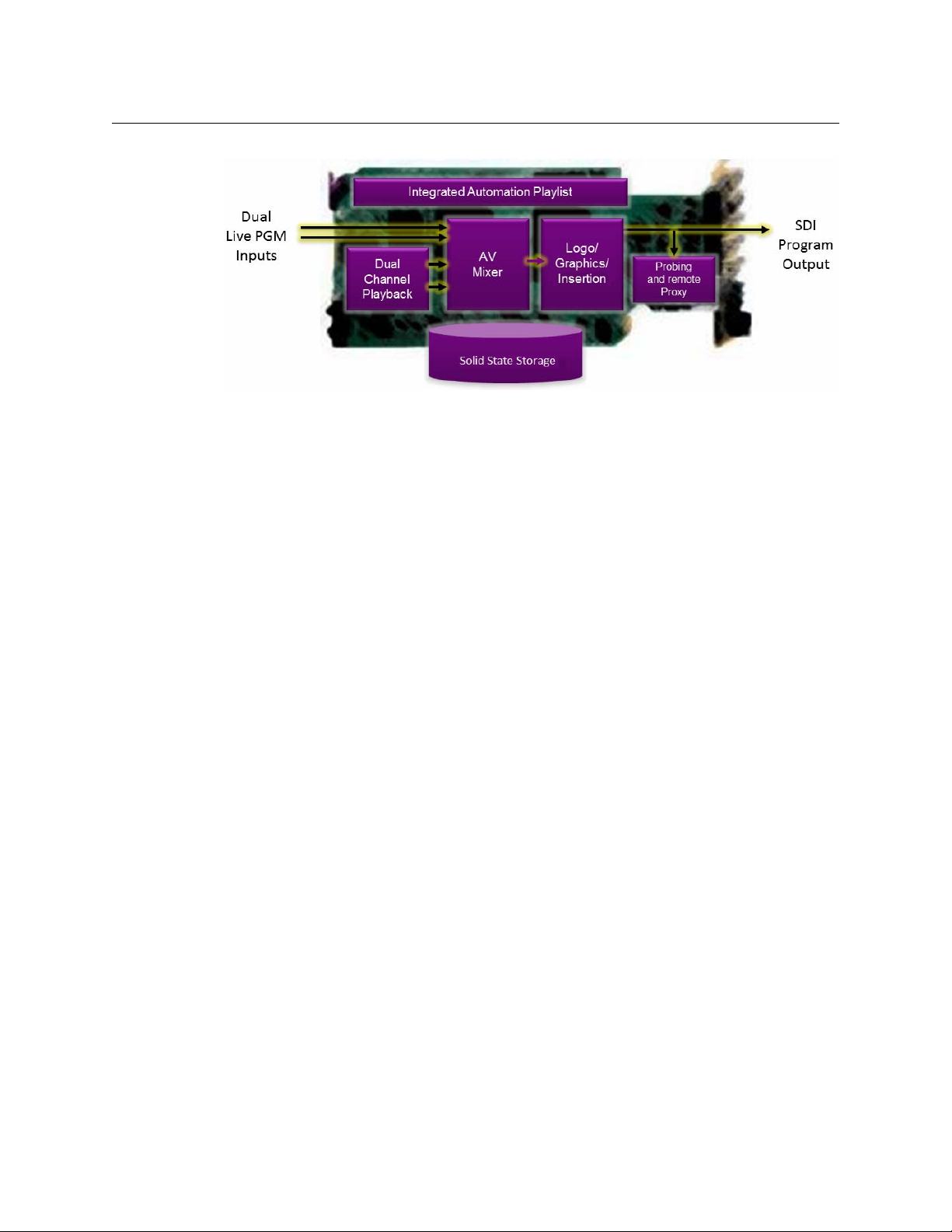
The Densité SSP-3801is a single card, solid state HD/SD playout server that is housed in the
Densité 3RU frame. It is fully integrated with the GV STRATUS Playout cloud-based
automation and schedule management service and is equally suitable for deployment at a
regional site or within a network operation center. The SSP-3801 card uses solid state
storage and broadcast hardware technology, with no reliance on external databases,
resulting in low cost of ownership, rock solid reliability, total frame accuracy, simple
installation and very low power consumption.
In addition to clip playback, the SSP-3801 card can display still and animated logos, highquality, pre-rendered graphical sequences and incorporate the output of external graphics
devices using a fill and key input.
The card features media storage that uses a unified file format (MXF Op1A) which is
compatible with an XDCAM HD or Sony IMX profile, and supports a bit rate of up to 100
Mbit/sec.
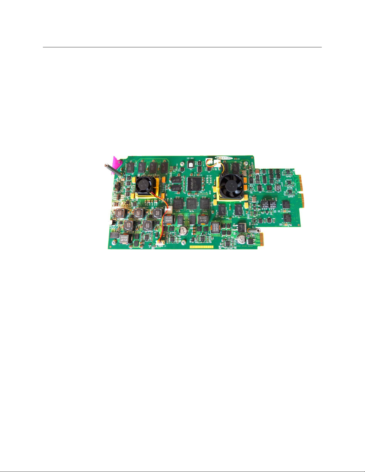
Key Hardware Features
The SSP-3801 is a “broadcast ready” playout solution, it has been designed to include all the
functionality to create a rich featured broadcast channel within in single package.
Fig. 1-1: HD/SD Solid-State Playout card (SSP-3801)
2
Page 7
SSP-3801
Installation and Configuration Guide
T
Fig. 1-2: Component layout of the SSP-3801 card
Its key hardware features include:
• All inputs and outputs support HD and SD (625, 525, 1080i and 720p at 50 and 59.94
frame rates)
• Frame accurate playback of clip media including video, multichannel audio and
ancillary data
• Fully configurable over a network interface and supports backup of configuration data
to Densité controller for hot swap functionality
• Solid State disks provide high performance, high reliability storage of HD material and
are available in three sizes: 375 GB, 775 GB and 1550 GB
• With its advanced embedded operating system allows the device will boot and can be
ready to take to air within 45 seconds
Key Software Features
The SSP-3801 card is designed to function as a part of the larger GV STRATUS Playout
solution and can be deployed in a number of configurations. Its key software features are:
• Full integration with GV STRATUS Playout using secure, open-standard web service
protocols to provide playlist input, status updates, thumbnails and alerts
• Provides full web interface for local control
• Supports live events including transitions and pass-through of video, audio and
ancillary data
• J2K graphics support
• Built-in voice-over playback support
• Seamless integration with supporting Grass Valley products such as Densité HCO
change-over card for main and backup playout applications, plus iControl
Key Operational Features
One of the design goals of this device was to lower operational costs and allow it to be
deployed in remote sites where local support is at a premium. To achieve this goal the
following features are available:
• All configuration and management can be provided by the network
3
Page 8

Introduction
Carriage of ancillary data in clips
• Configuring a new device can be as simple as inserting it into the Densité chassis with
all setup information being loaded based on the device location, which can be useful
for both new channels and replacing defective ones
• Provisioning and repair operations can be easily be performed with staff without
broadcast specific training
• Device will robustly continue to operate during temporary loss of connection to GV
STRATUS Playout using previously downloaded playlists or “evergreen” material
• SSP-3801 cards can pull broadcast media from a number of configured locations for
maximum resilience and flexibility
Carriage of ancillary data in clips
The SSP-3801 card can insert vertical ancillary (VANC) data from clips so that data such as
closed captions can be played out in sync with the video. VANC data can be carried in clips
in one of three ways:
• As a SMPTE 436M data track within the MXF
• As VBI lines encoded in the MPEG2 data (SD only - all Sony IMX files carry 16 lines of VBI)
• As ATSC A/53 closed captions within the MPEG2 elementary stream
The card operates with an “outside-in” model for handling vertical ancillary data. All SD
clips must be in the Sony IMX format and will therefore insert the first 16 lines of the MPEG
picture into the VBI space on the output. If ATSC A/53 closed captions are present in the
MPEG2 elementary stream, these will override 608 closed captions carried in the VBI lines in
the MPEG2 picture. If VBI lines are present in SMPTE 436M, this will overwrite the entire line
on the output and will consequently override both the MPEG A/53 closed captions and the
VBI lines in the MPEG2 Picture.
Supported media file formats
The SSP-3801 card supports the following formats. If the media files that you want to use
are not in a supported format, you can use the GV STRATUS Playout File Processing Node to
convert the files and the GV STRATUS Playout Media Import Application to register the
media files as assets in the GV STRATUS Playout service. For more information, see the
“Managing Assets” chapter of the GV STRATUS Playout Operator Guide.
Type Extension Description
Off Air slide OXT Oxtel Still format
Still OXT Oxtel Still format
Voice-over WAV 48kHz multi-channel WAV file (8, 16, 24 or 32 bit)
Graphic GMJ Transcoded by the
Logo • OXT
•OXA
Note: Floating point PCM data is not supported.
GV STRATUS Playout File
Processing Node
• Oxtel Still format
• Oxtel Animation format
4
Page 9

SSP-3801
Installation and Configuration Guide
Type Extension Description
Clip MXF Op1A XDCAM HD or Sony IMX
VANC VANC Created by csvanccreate.exe tool. For more
information, see VANC Packet Creation Tool in the SSP-
3801 User Guide.
Clip formats
XDCAM HD and Sony IMX are the only officially supported clip formats. Formats outside of
these profiles may function correctly; however, it is recommended that you validate the
media you wish to use. The following are the encoding parameters supported by the SSP3801 card.
Clip wrapper format
•OP1a MXF wrapper
Essence types
• Video - MPEG2
• Any bit rate up to 100Mbits/sec
• Long GOP or I-Frame only
• Full frame (SD or HD)
• Full frame plus 16 lines VBI (as per Sony IMX), SD only
• Frame coded only (field coded essence is not supported)
• A/53 MPEG closed captions
• Audio - PCM
• Up to 16 channels of audio
• Audio can be presented as any number of multi-channel tracks (1 track of 16
channels, 16 tracks of 1 channel, 8 tracks of 2 channels, and so on)
• 8-, 16-, 24-, or 32-bit PCM (big endian and little endian supported)
• Floating point PCM data is not supported
• Ancillary - SMPTE-436M
•8-bit VBI lines
•In luma plane (HD)
•In chroma plane (HD)
• Across both luma and chroma (SD)
• 1-bit and 10-bit VBI lines are not supported
• 8-bit ancillary packets
•In luma plane (HD)
•In chroma plane (HD)
• Across both luma and chroma (SD)
• 10-bit ancillary packets are not supported
5
Page 10
Introduction
What’s included with your product
Supported clip frame sizes
Video
Standard
625 720 576 25 SD/Interlaced, no VBI in picture
625 720 608 25 SD/Interlaced, VBI encoded in first 16 lines
525 720 480 29.97 SD/Interlaced, no VBI in picture
525 720 512 29.97 SD/Interlaced, VBI encoded in first 16 lines
1080i/50 1920 1080 25 HD/Interlaced
1080i/59.94 1920 1080 29.97 HD/Interlaced
720p/50 1280 720 50 HD/Progressive
720p/59.94 1280 720 59.94 HD/Progressive
Frame
Width
Frame
Height
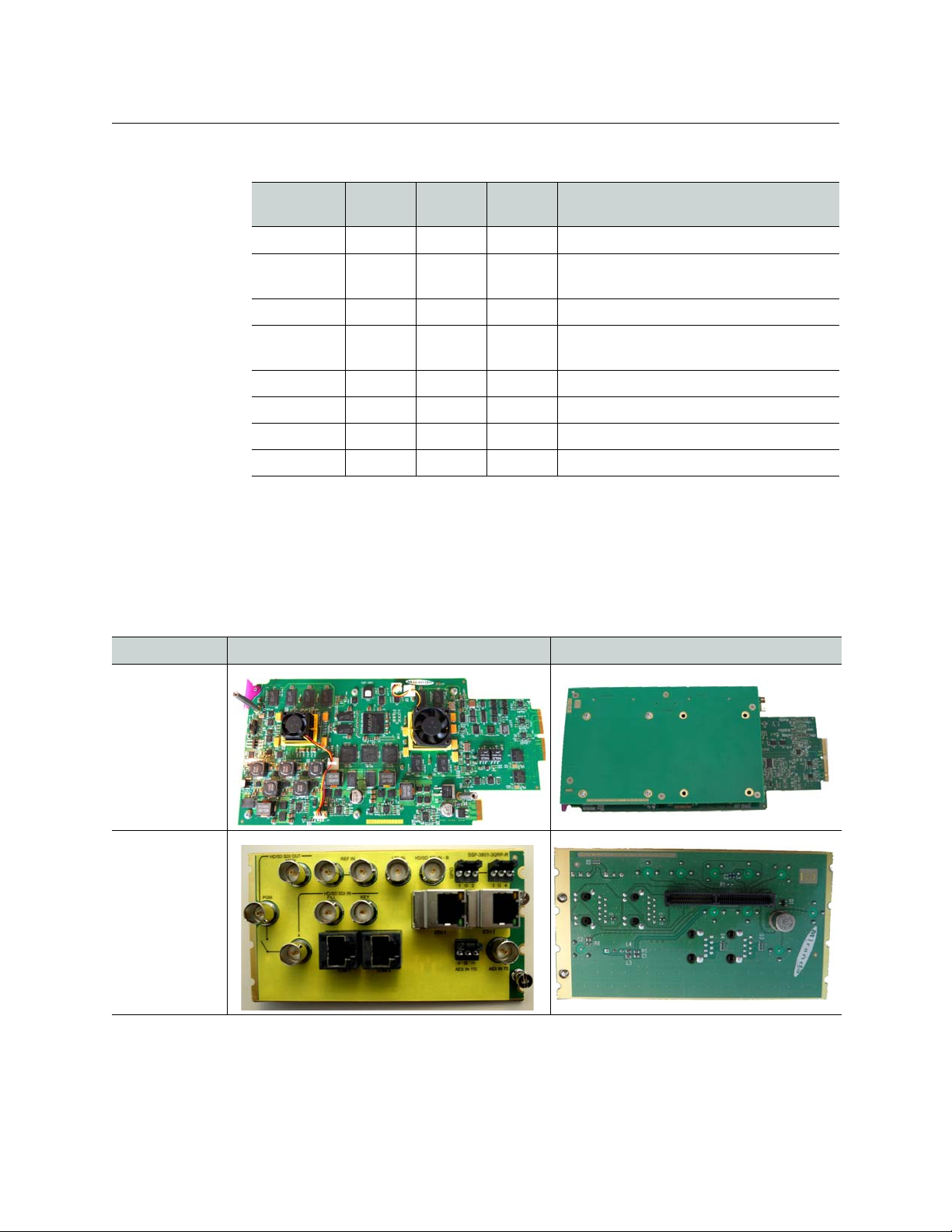
What’s included with your product
Each SSP-3801 package consists of two separate hardware components:
• One HD/SD SSP-3801 card
• One SSP-3801 rear connector panel
Frame
Rate
Notes
of picture (per field)
of picture (per field)
Component Front Rear
HD/SD SolidState Playout
card
SSP-3801 rear
connector panel
You can also access and download the complete SSP-3801 documentation by entering SSP3801 in the Search support files field on the Support Portal:
http://www.miranda.com/support/software/index
6
Page 11

Overview of the SSP-3801 card
This chapter provides an overview to the SSP-3801 hardware and software components,
including functional descriptions.
This chapter contains the following sections:
About the SSP-3801 card . . . . . . . . . . . . . . . . . . . . . . . . . . . . . . . . . . . . . . . . . . . . . . . . . . . . . . . . . . . . . . 8
Densité 3 frame’s local control panel . . . . . . . . . . . . . . . . . . . . . . . . . . . . . . . . . . . . . . . . . . . . . . . . . . 13
SSP-3801 web interface . . . . . . . . . . . . . . . . . . . . . . . . . . . . . . . . . . . . . . . . . . . . . . . . . . . . . . . . . . . . . . . 14
7
Page 12

Overview of the SSP-3801 card
Main board
Carrier board
Input/Output
connectors
Power & Densité 3
communication connector
About the SSP-3801 card
About the SSP-3801 card
The SSP-3801 is a playout server card that consists of two circuit boards assembled
together:
• The main board carries the bulk of the electronics with connectors that interface with
the SSP-3801 rear connector and Densité 3 frame mid-plane.
• The second board is a solid state drive (SSD) carrier board, which features up to two
SSDs for application and media storage.
Figure 2-1. The SSP-3801 card consists of two circuit boards
The SSP-3801 card has a connector which plugs into a mid-frame motherboard for
distribution of power and for connection to the controller card, with a second connector
which plugs directly into the rear connector panel for input and output.
Figure 2-2. SSP-3801 card connectors
8
Page 13
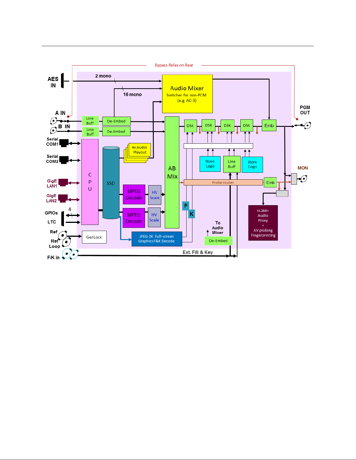
SSP-3801
Installation and Configuration Guide
Figure 2-3. Functional block diagram of the SSP-3801
9
Page 14
Overview of the SSP-3801 card
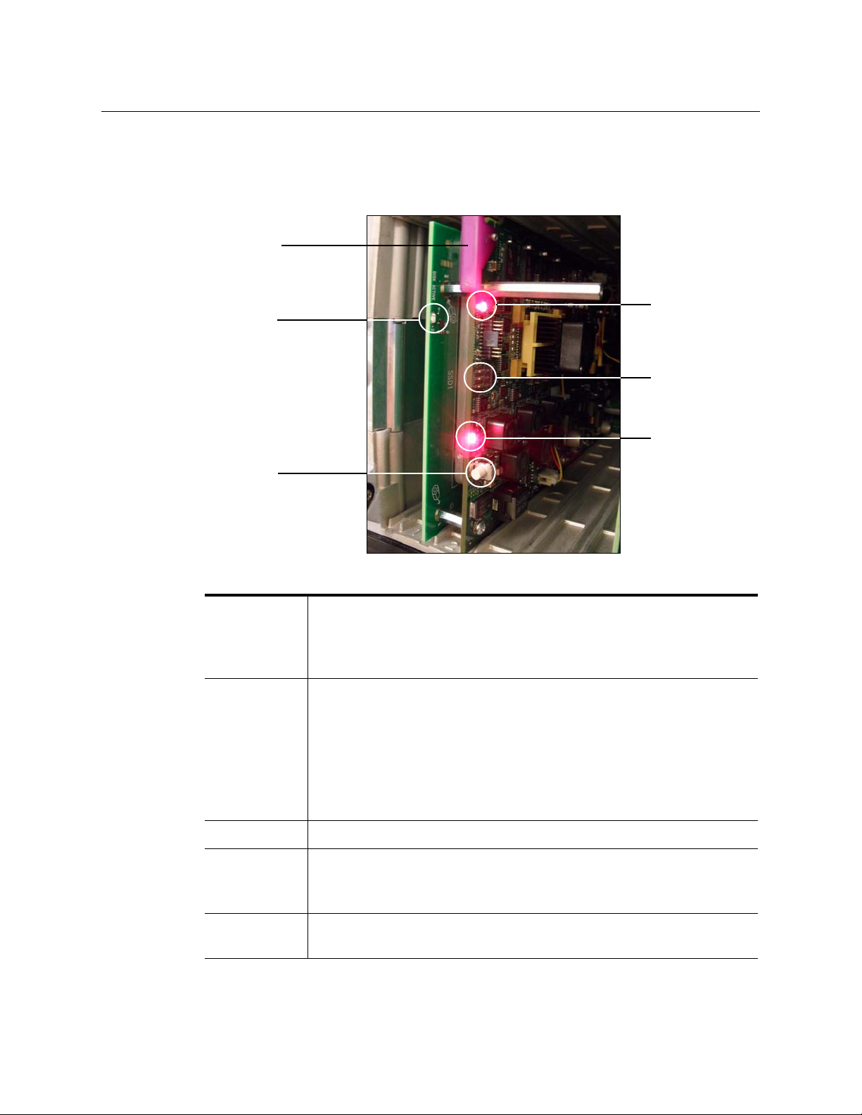
SSD LED
Select
button
Genlock LED
Console
Connector
Status LED
Ejector
SSP-3801 front card-edge components
SSP-3801 front card-edge components
The front card-edge features a series of LEDs that indicate card status and operations, as
well as provides an interface for testing and button to launch the control panel.
Figure 2-4. SSP-3801 card’s front edge components
Select button Pushing this button enables or disables the Densité 3 frame’s local control
panel to control the SSP-3801 card.
When the local control panel has control of the card, the Status LED flashes
yellow. See page 13 for more information.
Status LED This multi-color LED indicates the status of the SSP-3801 by color, and by
flashing or steady illumination.
• Green indicates no errors are occurring.
• Steady red indicates a major error.
• Flashing red indicates a critical error.
• Steady yellow indicates a minor error.
• Flashing yellow indicates that the card is selected for local control using
the
Densité 3 frame’s control panel.
SSD LED This blue LED indicates SSD activity.
Genlock LED This two-state LED indicates one of two states:
• Green indicates the SSP-3801 has locked to its configured reference.
• Red indicates that the reference could not be locked.
Console
Connector
Features a three-pin connector reserved for testing.
10
Page 15
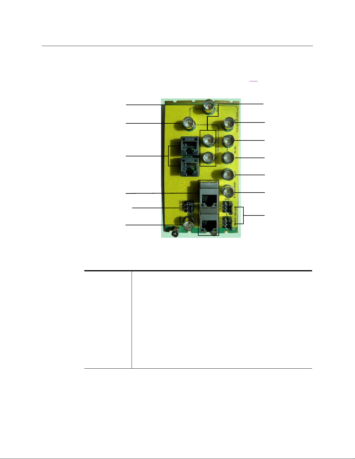
SSP-3801 rear connector panel
HD/SD SDI Out
HD/SD SDI In A
Serial Ports
COM1 & COM2
GigE Ethernet
ETH1 & ETH2
HD/SD SDI IN Fill
& Key
HD/SD SDI Out
Mon
Ref In
AES IN 110 ohms
AES IN 75 ohms
Ref Loop
LTC In
HD/SD SDI In B
GPIO
Like other Densité 3 cards, the SSP-3801 card interfaces with a separate rear connector
panel that must be fixed to the rear of the Densité 3 frame. Figure 2-5
input/output connectors featured on the rear connector panel.
SSP-3801
Installation and Configuration Guide
lists the required
Figure 2-5. SSP-3801 rear connector panel
The following table provides a brief description of each input/output socket on the rear
connector panel:
SDI Video I/O Three video inputs:
• HD/SD SDI In A (main program input)
•HD/SD SDI In B
• HD/SD SDI In - Fill & Key
Two video outputs:
• HD/SD SDI Out (PGM)
• HD/SD SDI Out - Mon (video monitoring & configurable as clean feed)
Note: The SSP-3801 is equipped with a mechanical bypass relay, which
sends the SDI IN A signal directly to the SDI Out (PGM) in cases of power
loss, card failure or a manual bypass command. The relay is not timed to
the same reference as the card and, therefore, it may not be a clean
switch. The timing of the switch and the time it takes to complete are not
guaranteed, which may cause some disturbance on the PGM output.
11
Page 16
Overview of the SSP-3801 card
Ω
Ω
SSP-3801 rear connector panel
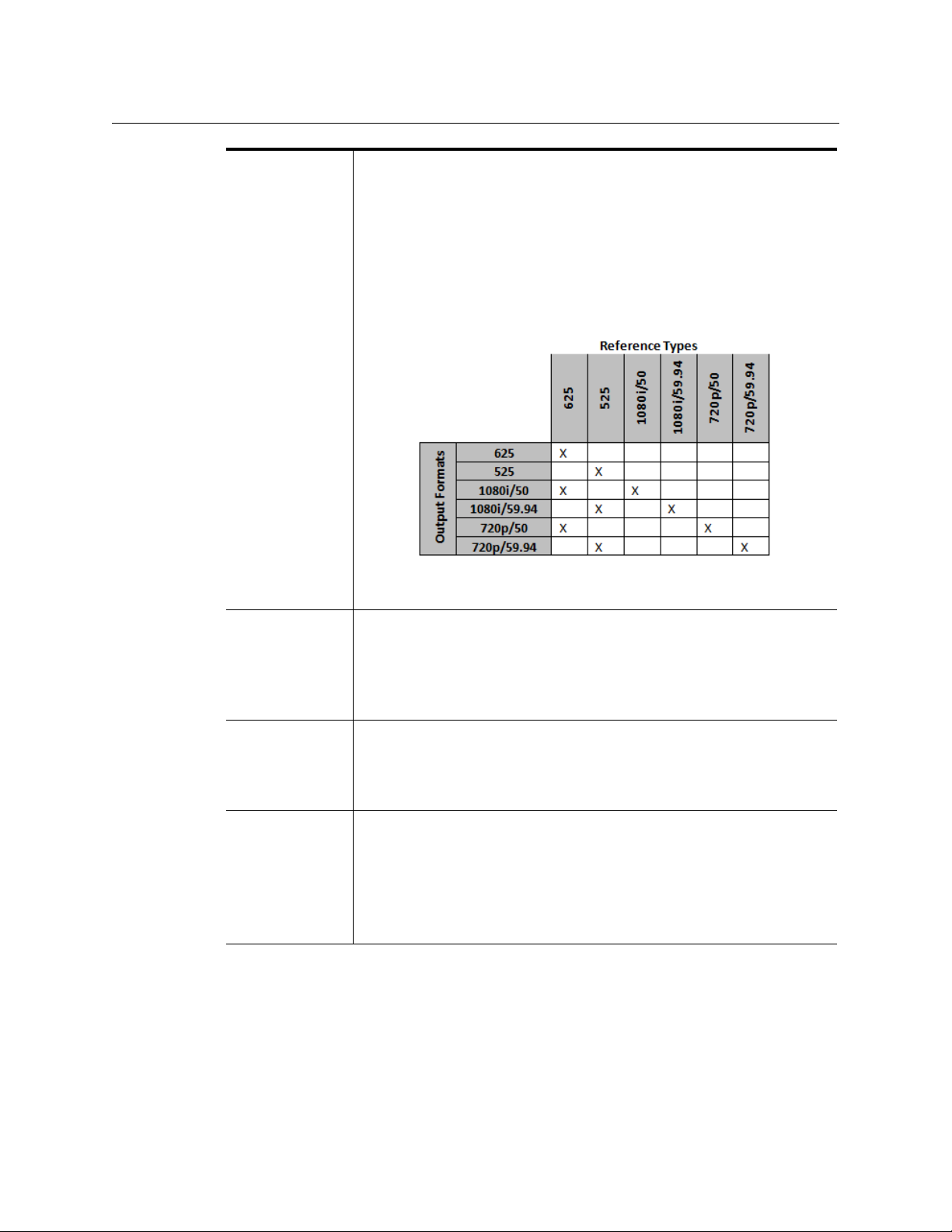
Reference Contains two reference connectors: Ref In and Ref Loop.
The analog reference input can be a black burst or tri-level sync (in both
50Hz and 59.94Hz formats) signal.
Note that the SSP-3801 also supports the internal
Densité 3 digital
reference (URS) provided by the REF-1801 card located in slot 10.
The SSP-3801 can also be configured to lock to the SDI A input signal.
The following chart identifies which reference format can be used with
which video format:
The Reference should be connected to Ref In, while Ref Loop should be
terminated if unused.
Audio I/O One discrete AES input available through two connectors:
• AES 110 - balanced
• AES 75 - unbalanced
The AES inputs are switchable and are mostly used for external audio or
voice-over applications.
Ethernet Ports Two 10/100/1000BASE-T Ethernet ports, which may be bonded to
support network redundancy or used in a dual homed configuration:
• ETH 1
• ETH 2
Serial COM Ports Two serial COM ports in the form of RJ-45 connectors:
• COM 1
• COM 2
These serial ports can be configured as RS-232 or RS-422. Each port’s
parameters can be set from the
Densité 3 frame local control panel.
Note: Not in use.
12
Page 17
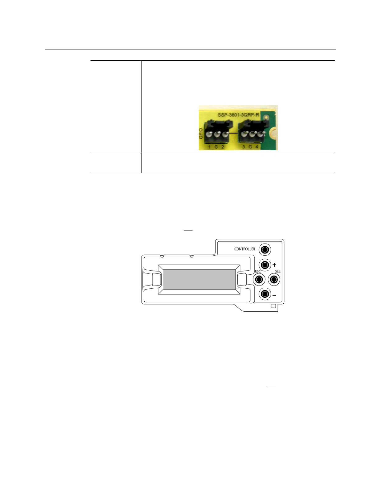
GPIO Two GPIO connectors offering up to four GPIOs, which can be
configured as general purpose inputs or outputs.
The pinouts are 1|G|2
the General Purpose Input/Output (GPIO) triggers in the SSP-3801 User
Guide.
LTC One Linear Timecode (LTC I n) connector to support time
synchronization.
Densité 3 frame’s local control panel
Like all other cards installed in a Densité 3 frame, the SSP-3801 is connected to the frame’s
controller card, which handles all interaction between the cards and the outside world. The
controller also supports remote operation via its Ethernet ports, and local operation using
its integrated control panel (figure 2-6
).
SSP-3801
Installation and Configuration Guide
and 3|G|4. For more information, see Configuring
Figure 2-6. The Densité 3 frame local control panel
With no operating controls located on the SSP-3801 card itself, you can use the Densité 3
frame’s local control panel to perform basic SSP-3801 configuration and control tasks. The
local control panel and its push-buttons provide you with a menu of parameters and allows
you to adjust parameter values. See Densité 3 Control Panel Menus on page 47 for a listing
of all the available parameters.
To gain control of the SSP-3801 card and browse the available parameters:
1Push the
Select button on the SSP-3801 card edge (see figure 2-4) to assign the local
control panel to operate the SSP-3801.
The SSP-3801 card’s
Status LED flashes yellow to indicated that it is the card currently
being controlled by the frame’s local control panel.
2 Use the following control panel buttons to navigate through the menu, as well as to
configure and adjust the SSP-3801 parameters and settings:
13
Page 18

Overview of the SSP-3801 card
SSP-3801 web interface
[+] [–] Used for menu navigation and value modification.
[SELECT] Gives access to the next menu level. When a parameter value
[ESC] Cancels the effect of parameter value changes that have not been
[CONTROLLER] Pushing the Controller button on the control panel selects the
SSP-3801 web interface
The SSP-3801 provides its own web-based user interface, which allows you to remotely
perform configuration, maintenance and control tasks, as well as monitor the state and
health of the card.
appears, pushing this button once enables modification of the
value using the [+] and [–] buttons; a second push confirms the
new value.
confirmed; pushing [ESC] causes the parameter to revert to its
former value.
Pushing [ESC] moves the user back up to the previous menu level.
At the main menu, [ESC] does not exit the menu system. To exit,
re-push the [SELECT] button for the card being controlled.
Controller card itself.
Some of the specific tasks that you may perform using the SSP-3801 web interface are:
• Device configuration
•Software upgrades
• Status monitoring
• Playlist view / emergency controls
• Advanced diagnostics / logging for in-field support
• H264 Confidence Monitor and audio meters
14
Page 19

SSP-3801
Installation and Configuration Guide
Fig. 2-7: The SSP-3801 web interface
For more information on configuring the SSP-3801 card, see Configuring the SSP-3801 card
on page 25.
15
Page 20

Overview of the SSP-3801 card
SSP-3801 web interface
16
Page 21

Installing the SSP-3801 card
This chapter explains how to install the SSP-3801 card in a Densité 3 frame, as well as how
to attach the cables. It also explains how to start the card and read its start-up status LEDs.
This chapter has the following sections:
Installing the rear connector panel . . . . . . . . . . . . . . . . . . . . . . . . . . . . . . . . . . . . . . . . . . . . . . . . . . . 18
Installing the SSP-3801 card . . . . . . . . . . . . . . . . . . . . . . . . . . . . . . . . . . . . . . . . . . . . . . . . . . . . . . . . . . 18
Starting the SSP-3801 card . . . . . . . . . . . . . . . . . . . . . . . . . . . . . . . . . . . . . . . . . . . . . . . . . . . . . . . . . . . 20
Installing a second on-board solid state storage drive . . . . . . . . . . . . . . . . . . . . . . . . . . . . . . . . . 21
Connecting a 110 ohm LTC signal to the card . . . . . . . . . . . . . . . . . . . . . . . . . . . . . . . . . . . . . . . . . 23
17
Page 22

Installing the SSP-3801 card
Installing the rear connector panel
Installing the rear connector panel
The SSP-3801 rear connector panel must be installed in the Densité 3 frame before the card
can be inserted.
Note: All Densité 3 cards and rear panels can be installed with the
frame power on. As a safety precaution however, we
recommend turning off power to the
the installation of the rear connector panel.
To install the rear connector panel:
1 If a card is installed in the slot whose rear panel is being changed, remove it or slide it
over by releasing the captive screw(s) at the bottom and then moving or removing the
card.
2 Position the SSP-3801 rear connector panel with the connectors facing outwards and
the captive screws at the bottom.
3 Secure the rear connector panel in place by tightening the captive screws at the
bottom.
Densité 3 frame during
Figure 3-1. SSP-3801 rear connector panels installed in a Densité 3 frame
Installing the SSP-3801 card
Once a matching rear connector panel has been installed, you can install the SSP-3801 card.
18
Page 23

Installation and Configuration Guide
Input/Output slots
Power and Densité 3
communication slot
Ejector handle
To install the SSP-3801 card, follow these steps:
1 Open the front panel of the frame.
2 Slide the SSP-3801 card into the slot and push gently on the
connectors (figure 3-2
).
Ejector handle to seat the
The card should be inserted into the far left slot associated with the SSP-3801’s 4-slot
rear panel. If you insert the card into the wrong slot, the on-card status LED will flash
red to indicate that there is no connection to the rear panel.
Ensure that the card is in the correct slot to prevent damage to itself or other hardware
in the frame.
SSP-3801
3 Close the front panel of the frame.
Figure 3-2. Inserting the SSP-3801 card into the Densité 3 frame
Note: To remove an existing SSP-3801 card from the slot, tilt up the
swivel handle on the front of the card to lever the connectors
apart, then use the handle to pull the card straight out of the
slot.
19
Page 24

Installing the SSP-3801 card
PGM SDI
Output
A SDI Input
(optional)
Ethernet
Port ETH1
REF IN
(optional)
Cabling the SSP-3801 card
Cabling the SSP-3801 card
Cabling the SSP-3801 depends upon your intended use. Note that the scope of this
document is limited to setting up the SSP-3801 card for basic start-up functionality. As
such, you should ensure that the following connections are made to the rear connector
panel of the SSP-3801 card.
• Connect a network Ethernet cable to the ETH1 Ethernet port. Note that the default
configuration is to provide redundant bonded networking with ETH1 as primary and
ETH2 for redundancy.
•Connect the
or a router input, for example.
• Optional - Connect an external reference source to
• Optional - Connect HD/SD SDI source input to A (SDI IN A)
Information about the remaining input-output connections are provided on page 11.
PGM (SDI Output) to downstream equipment such as a broadcast monitor
REF IN
Figure 3-3. Basic SSP-3801cabling connections
Starting the SSP-3801 card
Once the SSP-3801 rear connector panel and card have been installed, power up the
Densité 3 frame and ensure that the card is running properly.
20
Page 25

SSP-3801
Genlock LED
Status LED
Select
button
Installation and Configuration Guide
To start the SSP-3801 card:
1 If it is not already done, power up the Densité 3 frame with the SSP-3801 card properly
inserted.
The card will run its start up procedure.
2 Once the card’s start-up procedure is complete, ensure that the card’s Status and
Genlock LEDs are illuminated.
3 Press the SSP-3801’s
Select button on the card’s front-edge. Ensure that the Densité 3
frame’s local control panel properly displays SSP-3801 and the slot number, followed
Status menu item.
by its
Installing a second on-board solid state storage drive
If you require additional storage space for media, you can order and install a second solid
state storage drive (SSD) on the card.
21
Page 26

Installing the SSP-3801 card
First SSD
Location to install
the second SSD
Installing a second on-board solid state storage drive
Figure 3-4. positions of the SSDs
To install the second SSD:
1 Log into the card’s web interface. For more information see Logging into the SSP-3801
card’s web interface on page 26.
2 Obtain and enable the OPT 2SSD license. For information about how to enable a
license, see “Enabling or disabling a license option” in the User Guide.
3 From the menu, select Restart and click Safe Shutdown.
4 Once shutdown is complete, remove the SSP-3801 card from the Densité 3 frame.
5 Install the second SSD:
• Locate the first SSD in between the front and rear of the card. The second SSD is
installed next to the first SSD.
• Hold the SSD so that the SATA connectors are in the correct position to align with
the connectors on the rear of the card.
• Carefully insert the second SSD into position beside the first SSD and slide it into
the connectors ensuring that the connection is well made.
• Screw the SSD into place with the screws provided.
6 Replace the SSP-3801 card into the Densité 3 frame.
7 When the card has rebooted, verify that the SSD was installed correctly. To verify:
• Open and log into the SSP-3801 card’s web interface (see page 26).
• From the menu, select Status Information > System and click Partitions. In the
Media Cache Partition section, the size should include the combined amounts of
22
Page 27

the two SSDs. If it does not, verify that the license was enabled correctly and the
SSD is well seated in the connectors.
Connecting a 110 ohm LTC signal to the card
A Linear Timecode (LTC) signal is an audio signal encoded with SMPTE timecode data with a
preferred range 1 to 2V used to support time synchronization between devices. The SSP3801 card provides one unbalanced input with a 75 ohm linear timecode BNC connector
LTC In ) which can be connected to an LTC generator to provide the card with a time code
(
source.
If your LTC generator generates a 110 ohm LTC signal, you must use a balun that converts a
110 ohm XLR connector to a 75 ohm BNC connector to connect your LTC generator to the
card.
SSP-3801
Installation and Configuration Guide
23
Page 28

Installing the SSP-3801 card
Connecting a 110 ohm LTC signal to the card
24
Page 29

Configuring the SSP-3801 card
This chapter provides you with instructions for performing the initial configuration tasks
required to get the SSP-3801 running so that you can verify for proper installation, as well as
perform basic playout operations.
This chapter contains the following sections:
About the configuration process . . . . . . . . . . . . . . . . . . . . . . . . . . . . . . . . . . . . . . . . . . . . . . . . . . . . . . 26
Setting and verifying the SSP-3801 default settings . . . . . . . . . . . . . . . . . . . . . . . . . . . . . . . . . . . 26
Logging into the SSP-3801 card’s web interface . . . . . . . . . . . . . . . . . . . . . . . . . . . . . . . . . . . . . . . 26
Running the Setup wizard . . . . . . . . . . . . . . . . . . . . . . . . . . . . . . . . . . . . . . . . . . . . . . . . . . . . . . . . . . . . 27
Configure the System Identity settings . . . . . . . . . . . . . . . . . . . . . . . . . . . . . . . . . . . . . . . . . . . . . . . . 28
Configure the Time settings . . . . . . . . . . . . . . . . . . . . . . . . . . . . . . . . . . . . . . . . . . . . . . . . . . . . . . . . . . . 31
Configure the Reference settings . . . . . . . . . . . . . . . . . . . . . . . . . . . . . . . . . . . . . . . . . . . . . . . . . . . . . . 33
Configure the Input / Output settings . . . . . . . . . . . . . . . . . . . . . . . . . . . . . . . . . . . . . . . . . . . . . . . . . 34
Creating a restore point for Hot Swap . . . . . . . . . . . . . . . . . . . . . . . . . . . . . . . . . . . . . . . . . . . . . . . . . 35
Managing the user profiles . . . . . . . . . . . . . . . . . . . . . . . . . . . . . . . . . . . . . . . . . . . . . . . . . . . . . . . . . . . 36
Managing the Device Access security settings . . . . . . . . . . . . . . . . . . . . . . . . . . . . . . . . . . . . . . . . . 37
Configuring HCO Control to support card redundancy . . . . . . . . . . . . . . . . . . . . . . . . . . . . . . . . 38
Configuring an external router for switching between live events . . . . . . . . . . . . . . . . . . . . . . 40
Resetting the configuration settings to factory defaults . . . . . . . . . . . . . . . . . . . . . . . . . . . . . . . 44
Recovering from a card failure . . . . . . . . . . . . . . . . . . . . . . . . . . . . . . . . . . . . . . . . . . . . . . . . . . . . . . . . 45
Verifying the accuracy of the SSP-3801 card’s settings . . . . . . . . . . . . . . . . . . . . . . . . . . . . . . . . . 45
25
Page 30

Configuring the SSP-3801 card
About the configuration process
About the configuration process
The following summarizes the tasks that you must perform to configure a brand new,
factory-configured SSP-3801 card.
1 Verify and set the SSP-3801 default settings.
2 Log into the SSP-3801 card’s web interface.
3 Configure the System Identity settings.
4 Configure the Timing settings.
5 Configure the Reference settings.
6 Configure the Input / Output settings.
7 Manage the list of Users.
8 Verify the accuracy of the SSP-3801 card’s settings.
9 Optional - Upgrading the SSP-3801 card’s software.
Setting and verifying the SSP-3801 default settings
In preparation for other configuration tasks, we recommend that you verify and ensure
some of the SSP-3801 settings are set to their default values, as well as taking note of the
SSP-3801 card’s current IP address.
To verify and set the default settings, follow these steps:
1 Press the SSP-3801’s Select button on the card’s front-edge.
2 Ensure that the Densité frame’s local control panel properly displays SSP-3801 and the
slot number, followed by its Status menu item.
3Using the Select button on the local control panel, navigate to Status > Network
Status > IP Status > ETH1 > DHCP Enable and set it to Enable.
4Press the Escape button once, then the [ - ] button to display the current IP Address
assigned to the SSP-3801 card.
5 Take note of the IP address, which you will need to provide in a later step of the
configuration procedure.
6 If you connected two Ethernet cables with the intention to have them bonded for
redundancy, navigate back up to Status > Network Status > Bonded Enable and verify
that it is set to Enabled.
Logging into the SSP-3801 card’s web interface
The SSP-3801 web interface provides you with remote access to all of the parameters and
settings specific to a particular card. The following instructions demonstrate how to log
into the SSP-3801 web interface from any client computer that is on the same network as
the SSP-3801 card.
26
Page 31

Installation and Configuration Guide
IMPORTANT
To access the Solid State Playout-3801 web interface, we recommend
that you use a display with a minimum screen resolution of 1920 x 1080
pixels and the latest version of Google Chrome at 100% zoom in fullscreen (F11) mode.
To log into an SSP-3801 card’s web interface:
1 Type the IP address of the SSP-3801 card into the address bar of a web browser. By
default cards are factory-configured and shipped with DHCP enabled. You can obtain
the card’s initial IP address using the Densité local control panel (see page 26).
IMPORTANT
Later in the initial configuration procedure we recommend that you
disable the card’s DHCP setting and that you assign the card an
appropriate static IP address on your local network (see Configure the
System Identity settings on page 28).
SSP-3801
2 Specify a valid username and password and click OK.
If this is the first time you are logging into the SSP-3801, you should log in as follows:
• Username:
admin
• Password: P1ayout (the second character is the number 1)
IMPORTANT
If you are configuring the SSP-3801 card for the first time, we recommend
that you change password for the “admin” account. You cannot delete the
admin account. For more information, see Managing the user profiles on
page 36.
The SSP-3801 web interface opens. All of the card’s parameters and settings are
available within the thematic menus on the left of the page.
Running the Setup wizard
The Setup Wizard makes configuring the SSP-3801 card easy and efficient. When you
launch the Setup Wizard, it will prompt you with a series of dialog boxes to provide the
information required.
Figure 4-1. SSP-3801 Login page
27
Page 32

Configuring the SSP-3801 card
Configure the System Identity settings
The following are the types of information requested, followed by the menu command
where you can manually view or edit the information in the Card Configuration menu:
• Network Settings (System Identity, see Configure the System Identity settings on
page 28)
• Integration service settings (System Identity, see Configure the System Identity
settings on page 28)
• HTTP proxy server (System Identity, see Configure the System Identity settings on
page 28)
• Time sync settings (Time, see Configure the Time settings on page 31)
• NTP servers (Time, see Configure the Time settings on page 31)
• Time sync mode settings (Time, see Configure the Time settings on page 31)
• Reference settings (Reference, see Configure the Reference settings on page 33)
• Video standard settings (Input/Output, see Configure the Input / Output settings on
page 34)
Once you finish the Setup Wizard, you can run a system check to verify that the settings you
selected function with the SSP-3801 card.
To launch the Setup Wizard:
1 From the menu, select Card Configuration > Setup Wizard. The Setup sequence
begins.
2 Complete the fields as required and click Next to continue.
If you wish to go back and change your values, click Previous to move back and click
Next to move forward.
3Click Finish. The settings you selected will be applied immediately.
4The System Health Checks prompts you to check the settings you have selected are
functional. You have two choices:
• Run Checks: runs a system check to ensure that there are no conflicts. All valid
connections are listed, as well as any conflicts or failures.
• Close: closes the dialog box.
Configure the System Identity settings
Use the System Identity page to configure the SSP-3801 card’s identity, network, GV
STRATUS Playout service and HTTP settings. When a card is configured and a restore point is
created, its identity settings are stored in the Densité frame’s memory. If changes are made
to the System Identity settings, you must create a new restore point otherwise old settings
will be applied to the card upon insertion of a new card or a system restart.
When the card registers with the GV STRATUS Playout service, it stores a copy of its
configuration on the service and obtains the security certificate required for authentication.
You would only need to re-register the SSP-3801 card if:
• it was moved between deployments of the GV STRATUS Playout service
• it was deleted from the service
• it was disconnected for more than 6 months
28
Page 33

SSP-3801
Installation and Configuration Guide
As long as the card is connected to the service at least once every six months, the card will
manage the security certificate renewals itself.
IMPORTANT
Take special care when configuring the System Identity and the Time
settings. If there are inconsistencies in these parameters, the SSP-3801
card and the Playlist may not function properly.
To configure the system’s identity:
1 Open and log into the SSP-3801 card’s web interface (see Logging into the SSP-3801
card’s web interface on page 26).
2 From the menu, select Card Configuration > System Identity.
Figure 4-2. SSP-3801 web interface’s System Identity page
3In the General Networking Configuration section, complete the following settings:
• Host Name: Specify the network host name.
• Search Domains: Specify space-separated list of domains to search.
• Name Server 1 and Name Server 2: Specify the IP address or hostname of the
Domain Name System Server for each.
• Bonded Enable: If you connected two Ethernet cables with the intention to have
them bonded, select Enable. To disable Ethernet bonding, select Disable.
4In the Network Interface ETH sections, disable DHCP and assign static IP addresses:
• DHCP Enable: Select Disable.
• Specify the static IP Address, Netmask Address, and Gateway Address.
5In the Proxy Server field, type the HTTP Proxy server to use. If there is no proxy server
used, leave this field empty.
6Enable HTTPS certificate validation as required.
29
Page 34

Configuring the SSP-3801 card
Registering the card with GV STRATUS Playout service
IMPORTANT
If you have made any changes to the network settings, the system will
prompt you to restart the card. If you changed the IP address, you may
need to update the SSP-3801 web interface’s URL address before
proceeding with registering with the GV STRATUS Playout service.
7In the GV STRATUS Playout Integration section, configure the following:
•In the Deployment field, click the name of the deployment to which the SSP-3801
card will be registered. The URL of the selected deployment appears in the URL
field. If you selected Use custom URL, type the URL address for your GV STRATUS
Playout service in URL field.
• The deployment setting must be saved before the remaining settings can be
configured. Click Save.
•In the Data Centers field, click the name of the data center serving your GV
STRATUS Playout service.
•In the Registration Code field, type the key provided by the GV STRATUS Playout
service and click Register.
8Click Save to apply all changes on the page.
IMPORTANT
Once you have finished configuring all the settings on the card, make
sure you create a restore point otherwise old settings will be applied
upon insertion of a new card or a system restart.
Registering the card with GV STRATUS Playout service
If you did not register the card with the GV STRATUS Playout service when you configured
the System Identity, you can do so separately. Once the card is registered to a device in the
service, the Playlist and the Channel Configuration are managed by the service. The service
will overwrite any changes in those pages as long as the card remains synced with it.
When the card registers with the service, it stores a copy of its configuration on the service
and obtains the security certificate required for authentication. If you have already created
a Densité Restore Point, you must create a new restore point after registering the card or
old settings will be applied upon insertion of a new card or a system restart.
To register the card:
1 Open and log into the SSP-3801 card’s web interface (see page 26).
2 From the menu, select Card Configuration > System Identity.
3In the GV STRATUS Playout Integration section, configure the following:
•In the Deployment field, click the name of the deployment to which the SSP-3801
card will be registered. The URL of the selected deployment appears in the URL
field. If you selected Use custom URL, type the URL address for your GV STRATUS
Playout service in URL field.
• The deployment setting must be saved before the remaining settings can be
configured. Click Save.
30
Page 35

•In the Data Centers field, click the name of the data center serving your GV
STRATUS Playout service.
•In the Registration Code field, type the key provided by the GV STRATUS Playout
service and click Register.
4Click Save.
IMPORTANT
Once you have finished configuring the System Identity settings on the
card, make sure you create a restore point otherwise old settings will be
applied upon insertion of a new card or a system restart.
Configure the Time settings
Use the SSP-3801 web interface’s Time page to configure the SSP-3801 card’s time settings.
The card uses and displays time in UTC. It obtains its time from the source selected as the
Time Source:
• VITC: the time code is carried as part of the reference signal configured in Card
Configuration > Reference.
• LTC: the card obtains its time from the LTC generator connected to the LTC In connector.
• URS: time is provided to the card by a reference card installed in the Densité frame.
• ATC_LTC, ATC_VITC1, ATC_VITC2: time is obtained from the embedded time code in the
ancillary data coming from the SDI input.
• NTP: The card obtains its time from the NTP server listed in the NTP section.
SSP-3801
Installation and Configuration Guide
As a best practice, you should choose a time source other than NTP since NTP is not
accurate and tends to drift, which means time synchronization needs to be continuously
performed to keep the NTP and the video clock in sync. Other time code sources are more
accurate and stable sources of time. If there is no valid signal from the time source,
however, the card will fail to set the time and will eventually free run. It will not default to
using the NTP servers as a time source.
When the selected Time Source is in UTC, you do not need to configure the Time Zone or
Daylight Saving sections. If the Time Source is Local, then you need to configure the Time
Zone or Daylight Saving sections so the card can internally convert the time to UTC.
The card obtains the date from the NTP servers listed in the NTP section. The date and time
provided by the NTP server must always be in UTC since it can also be used as a reference
time to verify if the video time is in UTC. In addition to providing the NTP servers as the
source for the date, it is important to configure the Densité frame with a valid date and time
since it serves as a backup source for the date.
IMPORTANT
Take special care when configuring the System Identity and the Time
settings. If there are inconsistencies in these parameters, the SSP-3801
card and the Playlist may not function properly.
To configure the Time settings:
1 Open and log into the SSP-3801 card’s web interface (see page 26).
31
Page 36

Configuring the SSP-3801 card
Configure the Time settings
2 From the menu, select Card Configuration > Time.
Figure 4-3. SSP-3801 web interface’s Time page
3In the Time Source list, select the time source from which the SSP-3801 card obtains its
local time. If present, select
NTP.
VITC, LTC, URS or one of the ATC options, otherwise select
IMPORTANT
It is recommended that you use one of the other time sources instead of NTP
since they are more stable. NTP is not accurate and is likely to drift from the
video clock, which means it will likely require continuous time
synchronization to keep the NTP and video clock in sync.
4 Set the Time Source Type setting to either
UTC or Local to reflect which time zone the
selected Time Source is using.
5 If you selected Local as the Time Source Type, you must set the UTC Offsets so the card
can internally convert the time to UTC. In the Time Zone section, set the UTC Offset
sign, UTC Offset Hours, and UTC Offset Minutes to specify the difference between
Local and UTC time when Daylight Saving Time is not in effect.
6 If you selected Local as the Time Source Type, you must also set the Daylight Savings
settings so the card can make the appropriate adjustments when the time changes. In
the Daylight Saving section, specify the daylight saving time settings for the local time
zone:
•Click Enable.
• To configure when Daylight Saving Time begins, click the week of the month in the
Daylight Start Day list, click the day of the week in the Week Day list, click the
month in the Month list, and specify the time when the clocks move forward by
typing the hour in the HH field and the minutes in the MM field.
• To configure when Daylight Saving Time ends, click the week of the month in the
Daylight Stop Day list, click the day of the week in the Week Day list, click the
32
Page 37

SSP-3801
Installation and Configuration Guide
month in the Month list, and specify the time when the clocks move backward by
typing the hour in the HH field and the minutes in the MM field.
• To specify the difference between local and UTC time when Daylight Saving Time is
in effect, select the plus or minus sign in the Daylight Saving Bias sign list and type
the number of minutes in the MM field. The Daylight Saving Bias is the offset value
when a clock is set to automatically change according to Daylight Saving Time,
which means it is normally -60 (minus sixty minutes) in areas that practice Daylight
Saving Time and 0 (zero) in areas that do not.
7In the NTP section, specify the IP address or hostname in the NTP Server 1 and NTP
Server 2 fields for the two network time servers that will be used for obtaining the date.
The NTP date must be always in UTC.
8In the Time Synchronisation Settings section, set the Sync Mode to determine how
the SSP-3801 will synchronize its time to the time source:
• Continuously: Time adjustments are made continuously.
• At Specified Time: Time adjustments are scheduled for specific times. Type the
hours in the HH field and minutes in the MM field.
• Never: Time adjustments are never applied.
The Jam Sync button can be used at anytime to manually force the time
synchronization.
9Click Save to apply all changes.
Configure the Reference settings
Use the SSP-3801 web interface’s Reference page to configure the card’s reference signal
settings. The Input Timing section displays the current state of the timing between the
reference signal and the SDI input signals. One of the following states is displayed for each
input:
• Locked: a valid SDI input signal is present and locked to the selected reference signal.
• Absent: an SDI input signal is not detected. This may indicate that no signal is present
or a problem with the cable is occurring.
• Mismatch: the SDI input standard does not match the configured output standard of
the card.
• Unlocked: the SDI input and the reference signal are not matching in frequency and
phase causing a vertical drift (the SDI input is free-running).
If the state is anything other than Locked, use the features in the Output Timing Config
section to synchronize the signals.
To configure the card’s reference settings:
1 Open and log into the SSP-3801 card’s web interface (see page 26).
2 From the menu, select Card Configuration > Reference.
33
Page 38

Configuring the SSP-3801 card
Configure the Input / Output settings
3 Specify the source of the reference signal in the Reference field. You have the following
choices:
• External Ref: Select if the source of the reference signal is an analog reference
input such as a black burst or tri-level sync signal.
• SDI PGM In: Select if you want the source of the reference signal configured to lock
to the HD/SD SDI In A input signal.
• URS: Select if the source of the reference signal is from an internal Densité digital
reference (URS) provided by the REF-1801 card located in slot 10.
4In the Output Timing Config section, you can manually set the output timing in lines
and microseconds using the two up/down boxes, or you can use the following buttons
to set the values based on input timings:
• Auto Set Minimum Latency: automatically calculates the minimum propagated
delay.
• Auto Set Maximum Input Tolerance: automatically calculates the maximum
tolerance for input timing or jitter changes.
As you adjust the output timing, the value in the Overall Status field changes. For the
card to function adequately, it is recommended that Overall Status show as “Overall
Timing is OK” and the GenLock Status to display “Reference Locked”.
5Click Save to apply all changes.
Fig. 4-4: SSP-3801 web interface’s Reference page
Configure the Input / Output settings
Use the SSP-3801 web interface’s Input/Output page to configure the card’s input/output
settings and then optionally test the card’s playout to ensure proper operation.
To configure the SSP-3801 card’s input/output settings:
1 Open and log into the SSP-3801 card’s web interface (see page 26).
2 From the menu, select Card Configuration > Input/Output.
34
Page 39

SSP-3801
Installation and Configuration Guide
Fig. 4-5: Input/Output page
3In the Video Standard list, select the video standard that the card will output.
4In the Monitor Output Source list, select the source to be sent to MON, which can be
used as a troubleshooting aid, for sending a clean feed, or previewing a source event
about to go to air when router control is enabled.
5 Optional: If you have cabled the card to a downstream broadcast monitor, you can
verify if the card is operating properly by selecting the Test Pattern Enabled checkbox.
Once you have saved the changes, a test pattern from the SSP-3801 card will playout to
the broadcast monitor. When you can confirm that the test pattern plays out, clear the
Test Pattern Enabled checkbox, and click Save again.
6 If you selected an SD standard, you can choose whether line 23 in PAL (625 Line) or lines
20 and 21 in NTSC (525 Line) contain video or carry closed captioning or widescreen
signaling (WSS). To carry closed captioning or widescreen signaling, select the Pass
Closed Captions/WSS checkbox.
7In the AES Input Source list, select which type of AES cable is connected to the card.
8Click Save to apply the changes.
Creating a restore point for Hot Swap
Before a Hot Swap can be performed, a restore point must be created. A restore point is a
copy of the SSP-3801 card's identity settings stored in the Densité frame’s memory. The
restore point includes all the settings configured on the Card Configuration > System
Identity page, except for the Data Centers value.
If changes are made to the System Identity settings, you must create a new restore point
otherwise old settings will be applied to the card during a system restart or upon insertion
of a new card such as when you switch a card in a Densité frame without powering-down
the system, which is known as a Hot Swap. For more information on Hot Swap, see
"Switching SSP-3801 cards in a Densité frame (Hot Swap)" in the SSP-3801 User Guide.
A restore point can be created by using one of these methods:
• If the Densité controller and the SSP-3801 card are on the same network, you can
generate the restore point from the SSP-3801 web interface.
• You can save the SSP-3801 card’s identity via the Densité controller’s web interface.
35
Page 40

Configuring the SSP-3801 card
Managing the user profiles
• You can save the SSP-3801 card’s identity using the front panel of the Densité
controller.
To create a restore point from the SSP-3801 card’s web interface:
1 Open and log into the SSP-3801 card’s web interface (see page 26).
2 From the menu, select Card Configuration > Hot Swap.
3In the Controller IP Address field, type the IP address of the Densité frame hosting the
card.
4Click Save Identity.
Fig. 4-6: Hot Swap page
Managing the user profiles
To access the web interface for the SSP-3801 card, you need to login using a User Profile.
Every SSP-3801 card had a default admin account, but you can create other user profiles for
the other types of access. You can create two types of User Profiles:
• Standard User: has access to the following features:
• Status Information
•Playlist
•Audio Meters
• Alarms (view only)
•Media Cache Status
• Confidence Monitor
•Log Viewer
•Diagnostics
•Restart
•Card Options
• Administrator: has everything that a Standard User would have, plus
• Card Configuration
• Channel Configuration
•Software Upgrade
• Status Element Debug
36
Page 41

SSP-3801
Installation and Configuration Guide
IMPORTANT
If you are configuring the SSP-3801 card for the first time, we recommend
that you change password for the “admin” account. Although you can
change its password, you cannot rename or delete the admin account.
To manage the User Profiles:
1 Open and log into the SSP-3801 card’s web interface (see page 26).
2 From the menu, select Card Configuration > Security. The Users section contains the
current list of user profiles.
3 To create a user profile, click Add. The User Details dialog box appears.
:
Fig. 4-7: User Details dialog box
4 Enter the following information about the new user profile:
• Name: enter the name to use when logging into the system (this field is casesensitive).
• Password: enter the password for this user profile. The password is case-sensitive
and should be a combination of letters and numbers.
• Level: select the level of access for this user. You have two choices:
• Standard User: restricted access to manage media and add events to the
Timeline
• Administrator: full access to all the SSP-3801 features
5Click OK.
To edit or delete a user profile:
1In the Users section, select the user profile you want to modify.
2 Click one of the following:
• Edit: opens the User Details dialog box. Change the user profile fields and click OK.
• Delete: the user profile is removed from the list of profiles. This user will no longer
be able to log into the system.
Managing the Device Access security settings
The SSP-3801 card is configured with the firewall enabled by default that only accepts
connections using HTTPS and denies access to all other protocols. You can configure the
firewall to grant access from other protocols; however, a security alarm will be triggered if
access is enabled. You can change the severity of the alarm by changing its GSM Error Level
to Normal (see "Managing card alarms" in the SSP-3801 User Guide).
37
Page 42

Configuring the SSP-3801 card
Configuring HCO Control to support card redundancy
To manage the security settings:
1 Open and log into the SSP-3801 card’s web interface (see page 26).
2 From the menu, select Card Configuration > Security.
3In the Device Access Settings section, you can select Enable to grant access to specific
protocols or select Disable to deny access. If the protocols disabled by default are
enabled, an alarm is raised.
• FTP Access: Allows incoming FTP connections. Default: disabled.
• SSH Access: Allows incoming SSH connections (secure shell). This protocol is
usually only used by technical support. Default: disabled.
• HTTP Access: Allows incoming HTTP connections. No alarm is raised if it is enabled
in conjunction with HTTPS Redirection otherwise an alarm is raised. Default:
enabled.
• RSTP Access: Allows incoming RSTP connections in order to use the H.264
confidence monitor. IMPORTANT: When RTSP Access is enabled, all ports between
6970 and 65535 are opened for UDP access; therefore, this should only be done if
the card is located on a secure network. Default: disabled.
• HTTPS Redirection: Redirects the user to use HTTPS (secure) when connections are
made using HTTP. It must be enabled if HTTP Access is enabled otherwise an alarm
is raised.
4 If you enabled FTP Access, type the password for the account in the FTP Password field.
5Click Save.
Configuring HCO Control to support card redundancy
An HCO device can be used to set up automatic failover between two SSP-3801 cards. The
HCO device can be installed in the same Densité frame as the cards or accessible on the
network. The HCO Control page only appears when an HCO is available in the system and
the OPT HCO license is enabled.
Note: If you intend to configure the HCO device to automatically perform
the failover to the backup card in the event of a failure on the main card, the
Switch Mode on the HCO device must be set to the Toggle option.
The Toggle option enables the HCO device to automatically switch from one
input to the other when alarm conditions trigger the switch. It will stay on
that input until you manually perform a switch back to the original input or
alarm conditions on the input trigger a switch back to the original input. For
more information on configuring the HCO device, see the HCO
documentation.
To configure the HCO:
1 Open and log into the SSP-3801 card’s web interface (see page 26).
2 From the menu, select Card Configuration > HCO Control.
38
Page 43

SSP-3801
Failover header
Installation and Configuration Guide
Fig. 4-8: HCO Control page
3For HCO Control Enable, select Enable to allow the HCO device to automatically
perform a failover to the backup card in the case of a failure on the main card. If you
want to disable HCO Control, select Disable.
4In the Communication Interface list, click the location of the HCO device:
• Network: select if the HCO device is installed in a Densité frame elsewhere in the
network.
• Densité Control: select if the HCO device is installed in the same Densité frame as
the SSP-3801 cards are installed.
5In the SSP Output To list, click the HCO input to which the card is wired.
Note: Only the first and second inputs are supported on HCO devices that
offer three inputs. If the HCO device switches to an input other than the
supported inputs (by using iControl or the front panel menu), both SSP-3801
cards will report their roles as Backup and could potentially cause an off-air
situation.
6In the HCO Slot list, click the slot number in the Densité frame where the HCO device is
installed.
7 If Network was selected, enter the IP address and port where the HCO device is
installed:
•In the Densité Controller IP field, type the Densité Controller’s IP address.
•In the Densité Controller Port field, type the port number used by the Densité
Controller to communicate with the cards.
8Click Save.
To verify if you have selected the correct input, the correct Role should appear in the
header when the input you selected matches the physical HCO input connected to the
card.
Fig. 4-9: Failover header
39
Page 44

Configuring the SSP-3801 card
Configuring an external router for switching between live events
Configuring an external router for switching between live events
To be able to switch between multiple live feeds, you must connect and configure an
external video router. The router is connected to both the card’s SDI A and SDI B inputs.
Once router control is configured, the card manages which router source on which input is
sent to PGM (SDI Out) output.
A router system is usually comprised of two components: the router controller and the
router frame. The router frame connects the video sources to destinations, which is called
making a crosspoint. The router controller controls when the router frame makes the
crosspoint and to which destination the video source is sent.
The card communicates with the router controller through a network control connection to
signal when to switch crosspoints. The switching between the sources can be made by
source events in the playlist.
The expected flow of events between the card and the router is:
• The card sends a crosspoint (XPT) request to the router controller.
• The router controller receives the request from the card, triggers the router frame to
make the crosspoint, and then checks that the router frame has made the crosspoint.
• The router controller sends a message to the card confirming that the crosspoint has
been made.
In reality many router controllers send the crosspoint complete confirmation message
before it checks if the crosspoint has been made or even before the router frame has
actually made the crosspoint. To prevent unwanted effects in the playout, you can
configure the Post Router Tally Delay to accommodate for the time between the
confirmation message and the actual crosspoint being made by the router frame. It is
important to determine the correct value to configure as the Post Router Tally Delay which
is specific to your system.
As the card manages the selection of the SDI inputs, it biases the routing so the primary live
feed is on the SDI A input. This enables the live feed from the router source to be
automatically passed from the SDI A input to the PGM (SDI Out) output via the mechanical
bypass relay in case of power loss or card failure, therefore ensuring that playout continues
uninterrupted. It also prevents an operator from having to figure out which input is in use if
the wrong source or a bad source is on the PGM output. By biasing the routing to the SDI A
input, the operator can be sure that changing the source on the SDI A input will correct the
feed on the PGM output.
To understand how the switch between inputs occurs, consider this example. Source event
LIVE1 is on air and routed to input A. A second source event, LIVE2, enters the pre-roll
window. LIVE2 is routed to input B and goes on air when LIVE1 is done. The card then sends
a request to the router controller to also route LIVE2 to input A so both inputs are receiving
the same feed. Once the card receives the confirmation message from the router controller
and the Post Router Tally Delay has expired, the card switches its PGM output from SDI B to
SDI A and the transition on air should be seamless. If the Post Router Tally Delay value is too
short, a flash of LIVE1 may be seen on air when the switch is performed as the router will
not have completed its route. For a seamless transition, the Post Router Tally Delay value
must be correct.
40
Page 45

Installation and Configuration Guide
Note: The card only supports ASCII 7-bit printable characters for
mnemonics, the asset IDs, and paths. For more information, see "About the
supported characters for asset IDs, paths, and mnemonics" in the SSP-3801
User Guide.
To configure the router:
1 Open and log into the SSP-3801 card’s web interface (see page 26).
2 From the menu, select Card Configuration > Router Control.
SSP-3801
Fig. 4-10: Router Control page
3In the Type list, select the type of router connected to the card. Click:
• None: to disable Router Control.
• Virtual Router: to enable a virtual test router. The virtual router does not perform
video switches, but allows the card to act as though an actual router is connected
so it can be used to test the behavior. For example, a Source primary event added
to the playlist will act as though it played out and the Log Viewer will be updated,
but no actual video switching is performed.
• CQX Compact Router: to enable control of an NVision Compact CQX router.
• NV9000 Router Controller: to enable control of an
NV9000 router control system.
4 Depending on the type of device selected, the options on the page will differ.
Configure the following as required by the selected type:
41
Page 46

Configuring the SSP-3801 card
Configuring an external router for switching between live events
Type Configuration
None No configuration is required.
Virtual Router To configure the virtual router:
1 In the
destinations (between 0 and 8,000) that you want available for the
test. For example, if you type 64, the virtual router will support 64
sources and 64 destinations.
2 In the
(between 0 to 2000 ms) representing the delay between when the
message is received from the router controller confirming that the
switch has been made and when the actual switch is performed by
the router frame. Since the virtual router does not actually
Router Size field, type the number of sources and
Post Router Tally Delay field, type the value in milliseconds
video switches, any value can be used.
3 The router settings must be saved and the router must be online
before the router destinations can be configured. Click
4 In the
inputs on the card. For each input:
Destinations section, define the router destinations for the
• Click the Select button.
• Click Refresh to obtain a list of the available router sources.
• Click the desired router source and click Select. To filter the list,
type the name of the router source in the Search field. To order
the list, click the arrows in the column headers.
perform
Save.
42
Page 47

Type Configuration
CQX Compact
Router
To configure the CQX Compact router:
1 In the
format of the NVision Compact CQX router.
2 In the
with the NVision Compact CQX router over the UDP protocol.
Normally, the port number should be 5194 unless it was configured
differently on the router itself. The card will automatically open the
defined port in the SSP-3801’s firewall.
3 In the
Compact CQX router. Normally, the user ID should be 61441 unless it
was configured differently on the router itself.
4 In the
(between 0 to 2000 ms) representing the delay between when the
message is received from the router controller confirming that the
switch has been made and when the actual switch is performed by
the router frame.
5 The router settings must be saved and the router must be online
before the router destinations can be configured. Click
6 In the
inputs on the card. For each input:
IP Address field, type the IPv4 address in dotted quad
Port field, type the port number used for communication
User ID field, type the user ID configured in the NVision
Post Router Tally Delay field, type the value in milliseconds
Destinations section, define the router destinations for the
• Click the Select button.
• Click Refresh to obtain a list of the available router sources.
• Click the desired router source and click Select. To filter the list,
type the name of the router source in the Search field. To order
the list, click the arrows in the column headers.
SSP-3801
Installation and Configuration Guide
Save.
43
Page 48

Configuring the SSP-3801 card
Resetting the configuration settings to factory defaults
Type Configuration
NV9000 Router
Controller
To configure the NV9000 router control system:
1 In the
format of the NV9000 router control system.
2 In the
with the NV9000 router control system using a TCP network
connection. Normally, the port number should be 9193 unless it was
configured differently on the
3 In the
• To generate a default user ID, select Automatic.
• To specify the user ID configured in the NV9000 router control
system, select Manual and type the user ID in the field. A
manually entered user ID is required when a specific user ID is
configured in the NV9000 router control system using the SE
Utilities tool for use with its access controls. In this case, the
same user ID must be used by the SSP-3801 card. For more
information, please refer to NV9000 router control system’s
documentation.
4 In the Post Router Tally Delay field, type the value in milliseconds
(between 0 to 2000 ms) representing the delay between when the
message is received from the router controller confirming that the
switch has been made and when the actual switch is performed by
the router frame.
5 The router settings must be saved and the router must be online
before the router destinations can be configured. Click
6 In the
inputs on the card. For each input:
• Click the Select button.
• Click Refresh to obtain a list of the available router sources.
• Click the desired router source and click Select. To filter the list,
type the name of the router source in the Search field. To order
the list, click the arrows in the column headers.
IP Address field, type the IPv4 address in dotted quad
Port field, type the port number used for communication
NV9000 router control system itself.
User ID field, choose one of the following:
Save.
Destinations section, define the router destinations for the
5Click Save to save the changes and activate router control.
Resetting the configuration settings to factory defaults
If changes to the SSP-3801 card have resulted in a broken configuration or you wish to
apply a factory defaults configuration, you can use the Reset Configuration button on the
Software Upgrade page to reset all the configuration settings, except the following, to their
default values:
• Card Configuration > System Identity settings
• Card Configuration > Security > Users entries
•Card Options
44
Page 49

Once the reset is performed, the SSP-3801 card is restored to its factory defaults
configuration while retaining the settings from the items listed above.
To reset the configuration settings:
1 Open and log into the SSP-3801 card’s web interface (see page 26).
2 From the menu, click Software Upgrade.
3Click Reset Configuration.
Recovering from a card failure
To recover from an SSP-3801 card that has fallen into an unresponsive state:
1 Remove the affected card from the Densité frame.
2 Reinsert the card into the Densité frame, while at the same time holding down the
card’s Select button until the card is acknowledged on the local control panel’s display.
3 Take note of the new IP address that has been assigned to the card and is now
displayed on the local control panel’s display.
4 On a client computer on the same network as the SSP-3801 card, enter the card’s new IP
address in a web browser. This launches the card’s DFU mode user interface, which
allows you to perform a software upgrade or a factory install of the SSP-3801
software.
SSP-3801
Installation and Configuration Guide
Verifying the accuracy of the SSP-3801 card’s settings
Once you have completed the configuration procedure, we recommend that you verify the
summary of the card’s settings.
To view the SSP-3801 card’s current settings:
1 Open and log into the card’s web interface (see page 26).
2 From the menu, click Status Information
Each submenu provides the current status of the various SSP-3801 card’s settings.
Figure 4-11. System > General page
3 Browse through the settings listed to ensure they are correct. If you discover any
erroneous settings, return to the appropriate page in the web interface to make the
correction.
and browse through its submenus.
45
Page 50

Configuring the SSP-3801 card
Verifying the accuracy of the SSP-3801 card’s settings
46
Page 51

Densité 3 Control Panel Menus
This Appendix lists the menus and sub-menus on the Densité 3 frame’s local control panel.
47
Page 52

About the Densité 3 frame’s local control panel
About the Densité 3 frame’s local control panel
The following table identifies the menu items, parameters and settings that are displayed
on the Densité 3 frame’s local control panel when the SSP-3801 is selected.
Instructions for how to use the local control panel’s buttons are provided on page 13.
To select the commands on the card’s control panel:
1Press the Select button for the card you wish to modify. The name of the card and its
slot number appear in the controller panel.
2Press the +/- buttons to select the menu you wish to view and press SEL. The submenu
appears in the panel. Press ESC to go back one menu.
3Press the +/- buttons to select the submenu/command you wish to use and press SEL.
Press ESC to go back one menu.
Status menu
You have the following menus, submenus, and commands to choose from:
• Status menu (see Status menu on page 48)
• Reference menu (see Reference SRC menu on page 50)
• Ethernet Options menu (see Ethernet Options menu on page 50)
• Versi on menu (see Version menu on page 51)
• Options menu (see Options menu on page 51)
• Serial Ports menu (see Serial Ports menu on page 52)
• Test Pattern menu (see Test Pattern menu on page 52)
• Setup menu (see Setup menu on page 52)
The Status menu displays the following options:
Submenus
Ref Status Ref Source Free Run
URS Mode Not Present
Ext Reference • Ext Ref Status > Unlocked | Locked
•Ext Standard
48
Page 53

Submenus
Network Status IP Status ETH1
• DHCP Enable > Disable | Enable
• IP address
•Net Mask
• Gateway
• MAC Address
ETH2
• DHCP Enable > Disable | Enable
• IP address
•Net Mask
• Gateway
• MAC Address
Bonded Enable Disable | Enable
Hostname Displays the domain name for the card.
Link Status ETH1
• Link Status> Status Up | Down
• Link Duplex> Full Duplex | Half
• Link Speed > 10 | 100 | 1000 MBPS
ETH2
• Link Status> Status Up | Down
• Link Duplex> Full Duplex | Half
• Link Speed > 10 | 100 | 1000 MBPS
Serial Status COM 1 Port Counters
•RX:0
•TX:0
•FE:0
•PE:0
•BRK:0
•OE:0
COM2 Port Counters
•RX:0
•TX:0
•FE:0
•PE:0
•BRK:0
•OE:0
SSP-3801
Installation and Configuration Guide
49
Page 54

Reference SRC menu
Submenus
Video Inputs A Input • Video Standard
• Video Mismatch > False | True
• Video Status > Unlocked | Locked
B Input • Video Standard
• Video Mismatch > False | True
• Video Status > Unlocked | Locked
Fill-1 Input • Video Standard
• Video Mismatch > False | True
• Video Status > Unlocked | Locked
Key-1 Input • Video Standard
• Video Mismatch > False | True
• Video Status > Unlocked | Locked
AES • Pair 1 CH1 > Error Unlocked | Locked
• Pair 1 CH2 > Error Unlocked | Locked
Timecode VITC • BAD INT | GOOD INT
• +00:00:00 ND
LTC • BAD INT | GOOD INT
• +19:19:19 ND
URS • BAD INT | GOOD INT
• +00:00:00 ND
Serial Number Displays the unique serial number for this card.
Rear Panel Type SSP-3801 3QRP
Reference SRC menu
The Reference SRC menu displays the following options:
Submenus
Reference SRC External Ref
Ethernet Options menu
The Ethernet Options menu displays the following options:
ATC_TLC • BAD INT | GOOD INT
• +00:00:00 ND
ATC_VITC1 • BAD INT | GOOD INT
• +00:00:00 ND
ATC_VITC2 • BAD INT | GOOD INT
• +00:00:00 ND
SDI PGM IN
URS
50
Page 55

Submenus
Ethernet
Options
SSP-3801
Installation and Configuration Guide
Bonded Mode • Enable
•Disable
Nameserver 1 > 000.000.000.000
Nameserver 2 > 000.000.000.000
Eth1 DHCP Status
IP Address
Network Address
Gateway Address
Eth2 DHCP Status
IP Address
Network Address
Gateway Address
Restart Network
Version menu
The Version menu displays the current version of the control panel software.
For example: 1.3.0-0123
Options menu
The Options menu displays the active licenses on the card. The following lists the available
licenses:
• OPT HCO: allows the card to drive a downstream HCO card
• OPT 2SSD: allows the use of a second SSD card
• OPT CLIP: allows you to play video clips in the events
• OPT PROXY: allows the use of a second confidence monitor
• OPT BR: allows you to display graphics in the events
• OPT RTR: allows you to configure an external video router
51
Page 56

Serial Ports menu
Serial Ports menu
The Serial Ports menu displays the following options:
Submenus
COM 1 Baud Rate • 1200 BPS
COM 2 Baud Rate • 1200 BPS
• 1800 BPS
• 2400 BPS
• 4800 BPS
• 9600 BPS
• 19200 BPS
• 38400 BPS
• 57600 BPS
• 115200 BPS
Standard • RS422
•RS232
• 1800 BPS
• 2400 BPS
• 4800 BPS
• 9600 BPS
• 19200 BPS
• 38400 BPS
• 57600 BPS
• 115200 BPS
Test Pattern menu
The Test Pattern menu displays the following options:
•Enable
•Disable
Setup menu
The Setup menu displays the following options:
Submenus
Video Standard • 625 Line
Standard • RS422
•RS232
•525 Line
• 1080I/59.94
• 1080I/50
• 720P/59.94
• 720P/50
52
Page 57

Grass Valley Technical Support
For technical assistance, please contact the Grass Valley Technical Support center nearest
you:
Contact Us
Americas
Office hours: 9:00 a.m. – 9:00 p.m. (EST)
Telephone: 1-800-547-8949
Fax: +1 514 335 1614
E-mail: support@grassvalley.com
Europe, Middle East, Africa, UK
Office hours: 9:00 a.m. – 6:00 p.m. (GMT)
Telephone: +44 118 952 3444
Fax: +44 118 952 3401
E-mail: eurotech@grassvalley.com
France
Office hours: 9:00 a.m. – 5:00 p.m. (GMT+1)
Telephone: +33 1 55 86 87 88
Fax: +33 1 55 86 00 29
E-mail: eurotech@grassvalley.com
Corporate Head Office
Asia
Office hours: 9:30 a.m. – 6:00 p.m. (GMT+8)
Telephone: +852 2539 6987
Fax: +852 2539 0804
E-mail: asiatech@grassvalley.com
China
Office hours: 9:30 a.m. – 6:00 p.m. (GMT+8)
Telephone: +86 10 5873 1814
E-mail: asiatech@grassvalley.com
Malaysia
Telephone: +60 3 2247 1808
E-mail: asiatech@grassvalley.com
EMERGENCY After Hours (Global)
Toll Free: 1-800-547-8949 (US and Canada)
Telephone: +1 514 333 1772
Grass Valley
3499 Douglas-B.-Floreani
St-Laurent, Quebec H4S 2C6
Canada
Telephone: +1 514 333 1772
Fax: +1 514 333 9828
Web: www.grassvalley.com
 Loading...