

Page 1

Instruction Manual
TP3473-01
FIRST PRINTNG: AUGUST 1995
REVISED PRINTNG: DECEMBER1997
SMS 8301A
COMPONENT ANALOG VIDEO TO SERIAL DIGITAL CONVERTER
Page 2

Contacting Grass Valley Group
Region Voice Fax Address Web Site
North America (800) 547-8949
Pacific Operations +852-2585-6688
U.K., Europe, Asia,
Middle East
France +33 1 45 29 73 00
Germany +49 221 1791 234 +49 221 1791 235
530-478-4148
Support: 852-2585-6579
+44 1753 218 777 +44 1753 218 757
Copyright © Grass Valley Group. All rights reserved.
This document may not be copied, in whole or in part, or otherwise reproduced,
except as specifically permitted under U.S. copyright law, without the prior written
consent of Grass Valley Group, P.O. Box 599000, Nevada City, CA 95959-7900 USA.
GRASS VALLEY GROUP is a registered trademark and Grass Valley is a trademark of
Grass Valley Group. All registered trademarks and trademarks are property of their
respective holders. Grass Valley Group products are covered by U.S. and foreign patents, issued and pending. Product options and specifications subject to change without
notice. The information in this manual is furnished for informational use only, is subject to change without notice, and should not be construed as a commitment by Grass
Valley Group. Grass Valley Group assumes no responsibility or liability for any errors
or inaccuracies that may appear in this publication.
(530) 478-3347 Grass Valley Group
+852-2802-2996
P.O. Box 599000
Nevada City, CA 95959-7900 USA
www.grassvalleygroup.com
Page 3

Contents
Important Safeguards and Notices
Symbols and Their Meanings in This Manual . . . . . . . . . . . . . . . . . . . . . . vii
Warnings . . . . . . . . . . . . . . . . . . . . . . . . . . . . . . . . . . . . . . . . . . . . . . . . . . . . . ix
Cautions . . . . . . . . . . . . . . . . . . . . . . . . . . . . . . . . . . . . . . . . . . . . . . . . . . . . . . x
Power Supply Cords . . . . . . . . . . . . . . . . . . . . . . . . . . . . . . . . . . . . . . . . . . . xi
North American Power Supply Cord . . . . . . . . . . . . . . . . . . . . . . . . . . xi
International Power Supply Cord . . . . . . . . . . . . . . . . . . . . . . . . . . . . . xi
EMC Regulatory Notices . . . . . . . . . . . . . . . . . . . . . . . . . . . . . . . . . . . . . . . . xii
Federal Communications Commission
(FCC) Part 15 Information . . . . . . . . . . . . . . . . . . . . . . . . . . . . . . . . . . . xii
89/336/EEC EMC Directive . . . . . . . . . . . . . . . . . . . . . . . . . . . . . . . . . xii
SMS 8301A Component Analog Video to Serial Component Digital Converter
Introduction . . . . . . . . . . . . . . . . . . . . . . . . . . . . . . . . . . . . . . . . . . . . . . . . . . . . 1
Function . . . . . . . . . . . . . . . . . . . . . . . . . . . . . . . . . . . . . . . . . . . . . . . . . . . . . . . 2
Signal Processing . . . . . . . . . . . . . . . . . . . . . . . . . . . . . . . . . . . . . . . . . . . . 4
Timing and Control . . . . . . . . . . . . . . . . . . . . . . . . . . . . . . . . . . . . . . . . . . 5
Specifications . . . . . . . . . . . . . . . . . . . . . . . . . . . . . . . . . . . . . . . . . . . . . . . . . . . 6
Installation . . . . . . . . . . . . . . . . . . . . . . . . . . . . . . . . . . . . . . . . . . . . . . . . . . . . . 8
Module Configuration . . . . . . . . . . . . . . . . . . . . . . . . . . . . . . . . . . . . . . . 8
Vertical Blanking Width Selection . . . . . . . . . . . . . . . . . . . . . . . . . . 9
8/10 Bit Output Selection . . . . . . . . . . . . . . . . . . . . . . . . . . . . . . . . 10
MII/BETA Format Configuration . . . . . . . . . . . . . . . . . . . . . . . . . 11
GBR Format Internal/External Sync Selection . . . . . . . . . . . . . . 12
Chroma Filter Selection . . . . . . . . . . . . . . . . . . . . . . . . . . . . . . . . . . 13
External Sync Source . . . . . . . . . . . . . . . . . . . . . . . . . . . . . . . . . . . . 14
Module Installation . . . . . . . . . . . . . . . . . . . . . . . . . . . . . . . . . . . . . . . . . 15
Rear Connectors . . . . . . . . . . . . . . . . . . . . . . . . . . . . . . . . . . . . . . . . . . . . 16
Inputs/Outputs . . . . . . . . . . . . . . . . . . . . . . . . . . . . . . . . . . . . . . . . 16
Remote . . . . . . . . . . . . . . . . . . . . . . . . . . . . . . . . . . . . . . . . . . . . . . . . 16
iii
Page 4

Contents
Index
Front Panel Controls/Displays . . . . . . . . . . . . . . . . . . . . . . . . . . . . . . 17
Front Panel . . . . . . . . . . . . . . . . . . . . . . . . . . . . . . . . . . . . . . . . . . . . 18
Input Format . . . . . . . . . . . . . . . . . . . . . . . . . . . . . . . . . . . . . . . . . . 18
Y Black Level Control . . . . . . . . . . . . . . . . . . . . . . . . . . . . . . . . . . . 19
Gain Controls . . . . . . . . . . . . . . . . . . . . . . . . . . . . . . . . . . . . . . . . . 20
Ref Present LED . . . . . . . . . . . . . . . . . . . . . . . . . . . . . . . . . . . . . . . 22
Module Alignment . . . . . . . . . . . . . . . . . . . . . . . . . . . . . . . . . . . . . . . . . . . . 23
Alignment Equipment . . . . . . . . . . . . . . . . . . . . . . . . . . . . . . . . . . . . . . 23
Free Run Frequency Adjustment . . . . . . . . . . . . . . . . . . . . . . . . . . . . . 24
Frequency Response Adjustment . . . . . . . . . . . . . . . . . . . . . . . . . . . . 25
Y/G Ref H Phase Adjustment . . . . . . . . . . . . . . . . . . . . . . . . . . . . . . . 26
Service . . . . . . . . . . . . . . . . . . . . . . . . . . . . . . . . . . . . . . . . . . . . . . . . . . . . . . . 27
. . . . . . . . . . . . . . . . . . . . . . . . . . . . . . . . . . . . . . . . . . . . . . . . . . . . . . . . . . . . Index-1
iv
Page 5

Contents
List of Illustrations
Figure 1. 8301A Block Diagram . . . . . . . . . . . . . . . . . . . . . . . . . . . . . . . . . . . 2
Figure 2. JP1 Jumper Settings . . . . . . . . . . . . . . . . . . . . . . . . . . . . . . . . . . . . . 9
Figure 3. JP101 Jumper Settings . . . . . . . . . . . . . . . . . . . . . . . . . . . . . . . . . . 10
Figure 4. JP102 Jumper Settings . . . . . . . . . . . . . . . . . . . . . . . . . . . . . . . . . . 11
Figure 5. JP103 Jumper Settings . . . . . . . . . . . . . . . . . . . . . . . . . . . . . . . . . . 12
Figure 6. JP600 Jumper Settings . . . . . . . . . . . . . . . . . . . . . . . . . . . . . . . . . . 13
Figure 7. JP900 Jumper Settings . . . . . . . . . . . . . . . . . . . . . . . . . . . . . . . . . . 14
Figure 8. 8301A Rear Connector Overlay . . . . . . . . . . . . . . . . . . . . . . . . . . 16
Figure 9. 8301A Front Panel . . . . . . . . . . . . . . . . . . . . . . . . . . . . . . . . . . . . . 18
Figure 10. 8301A Calibration Waveform . . . . . . . . . . . . . . . . . . . . . . . . . . . . 22
Figure 11. JP103 Jumper Settings . . . . . . . . . . . . . . . . . . . . . . . . . . . . . . . . . . 24
Figure 12. JP103 and JP200 Shorting Jumpers . . . . . . . . . . . . . . . . . . . . . . . 26
v
Page 6

Contents
List of Tables
Table 1. Format Selection . . . . . . . . . . . . . . . . . . . . . . . . . . . . . . . . 18
Table 2. Signal Levels . . . . . . . . . . . . . . . . . . . . . . . . . . . . . . . . . . . 19
vi
Page 7
Important Safeguards and Notices
Information on the following pages provides important safety
guidelines for both Operator and Service Personnel. Specific
warnings and cautions will be found throughout the manual
where they apply, but may not appear here. Please read and
follow the important safety information, noting especially those
instructions related to risk of fire, electric shock or injury to
persons.
WARNING
Any instructions in this manual that require opening the equipment
cover or enclosure are for use by qualified service personnel only.
To reduce the risk of electric shock, do not perform any servicing
other than that contained in the operating instructions unless you
are qualified to do so
.
Symbols and Their Meanings in This Manual
The lightning flash with arrowhead symbol, within an equilateral
triangle, alerts the user to the presence of “dangerous voltage”
within the product’s enclosure that may be of sufficient
magnitude to constitute a risk of electric shock to persons.
The exclamation point within an equilateral triangle alerts the
user to the presence of important operating and maintenance
(servicing) instructions in the literature accompanying the
equipment.
vii
Page 8
Section — Important Safeguards and Notices
This symbol represents a protective grounding terminal. Such a
terminal must be connected to earth ground prior to making any
other connections to the equipment.
The fuse symbol indicates that the fuse referenced in text must be
replaced with one having the ratings indicated.
viii
Page 9

Warnings
Warnings
Heed all warnings on the unit and in the operating
■
instructions.
Do not use this product in or near water.
■
■
Disconnect AC power before installing any options.
■
This product is grounded through the grounding conductor
of the power cord. To avoid electrical shock, plug the power
cord into a properly wired receptacle before connecting the
product inputs or outputs.
■
Route power cords and other cables so that they are not likely
to be damaged.
■
Disconnect power before cleaning. Do not use liquid or
aerosol cleaners; use only a damp cloth.
Dangerous voltages exist at several points in this product. To
■
avoid personal injury, do not touch exposed connections and
components while power is on.
Do not wear hand jewelry or watches when troubleshooting
■
high current circuits, such as the power supplies.
During installation, do not use the door handles or front
■
panels to lift the equipment as they may open abruptly and
injure you.
To avoid fire hazard, use only the replacement parts with
■
specified correct type, voltage and current rating as
referenced in the appropriate parts list for this product.
Always refer fuse replacement to qualified service personnel.
To avoid explosion, do not operate this product in an
■
explosive atmosphere unless it has been specifically certified
for such operation.
■
Have qualified personnel perform safety checks after any
completed service.
If equipped with redundant power, this unit has two power
■
cords. To reduce the risk of electric shock, disconnect both
power supply cords before servicing.
ix
Page 10

Section — Important Safeguards and Notices
Cautions
To prevent damage to equipment when replacing fuses, locate
■
and correct the trouble that caused the fuse to blow before
applying power.
Verify that all power supply lights are off before removing
■
power supply or servicing equipment.
Use only specified replacement parts.
■
■
Follow static precautions at all times when handling this
equipment.
■
Leave the back of the frame clear for air exhaust cooling and
to allow room for cabling. Slots and openings in the cabinet
are provided for ventilation. Do not block them.
■
The front door is part of the fire enclosure and should be kept
closed during normal operation.
■
This product should be powered only as described in the
manual. To prevent equipment damage select the proper line
voltage at the AC input connector as described in the
installation documentation.
■
Ensure that the two power supply cords are each plugged into
a separate branch circuit in case one circuit should fail.
■
Circuit boards in this product are densely populated with
surface mount and ASIC components. Special tools and
techniques are required to safely and effectively troubleshoot
and repair modules that use SMT or ASIC components. For
this reason, service and repair of Tektronix-GVP products
incorporating surface mount technology are supported only
on a module exchange basis. Customers should not attempt to
troubleshoot or repair modules that contain SMT or ASIC
components. Tektronix-GVP assumes no liability for damage
caused by unauthorized repairs. This applies to both in- and
out-of-warranty products.
x
Page 11

Power Supply Cords
There are two types of power supply cords available for the
SMS 8000 Series. Refer to one of the following, depending on the
location where the equipment will be used.
North American Power Supply Cord
This equipment is supplied with a molded grounding plug
(NEMA 5-15P) at one end and a molded grounding receptacle
(IEC 320-C13) at the other end. Conductors are color coded white
(neutral), black (line) and green or green/yellow (ground).
Operation of this equipment at voltages exceeding 130 VAC will
require power supply cords which comply with NEMA
configurations.
International Power Supply Cord
Power Supply Cords
This equipment is supplied with a molded grounding receptacle
(IEC 320-C13) at one end and stripped conductor (50/5 mm) at the
other end. Conductors are CEE color coded, light blue (neutral),
brown (line) and green/yellow (ground). Other IEC 320 C-13 type
power supply cords can be used if they comply with the safety
regulations of the country in which they are installed.
xi
Page 12

Section — Important Safeguards and Notices
EMC Regulatory Notices
Federal Communications Commission (FCC) Part 15 Information
This device complies with Part 15 of the FCC Rules. Operation is
subject to the following two conditions:
(1) This device may not cause harmful interference.
(2) This device must accept any interference received including
interference that may cause undesirable operations.
89/336/EEC EMC Directive
EN500081-1
EN55022
WARNING
xii
This is a Class A product. In a domestic environment this product
may cause radio interference, in which case the user may be
required to take adequate measures.
Page 13

SMS 8301A Component Analog Video to Serial Component Digital Converter
Introduction
The SMS 8000 product line consists of a 1RU frame which holds
up to 4 modules. The modules provide such functions as video
delay and format conversion. Modules are selected by the user to
suit their particular requirements.
The SMS 8301A CAV to Serial Component Digital Converter
Module accepts a component analog video (CAV) input (525 or
625 line) and converts it to an 8 or 10 bit 270 Mb/s serial
component digital signal per SMPTE 259M/EBU Tech 3267
standard.
8301A features are:
Automatically selects between 525 and 625 lines
■
■
Selectable Chroma Channel Bandwidth
■
Gain Calibration Display
■
Ten Bit A/D Conversion
Selectable Ten Bit Output or Dynamic Rounding to 8 Bits
■
■
Oversampling A/D Conversion
■
Input selectable MII, BETA, EBU N10, or GBR
Digital Filtering
■
■
Digital Clamping
■
525/625 Vertical Blanking Width (Narrow or Wide)
Selectable Internal or External Reference in GBR Mode
■
Remote Chroma Off Input
■
■
525/625 Line Standard Sense Output
1
Page 14
SMS 8301A Component Analog Video to Serial Component Digital Converter
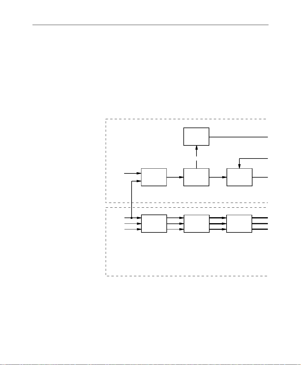
Function
This description is divided into two sections:
■
Signal Processing
■
Timing and Control
Refer to block diagram Figure 1 while reading the pages that
follow.
Reference
Vertical
Detector
Sync
External
Reference
Input
Amplifiers
and
Reference
Selector
Ref
Video
Timing and Control
Y/G
B-Y/B
R-Y/R
Analog
Processing
and Filtering
Y/G
B-Y/B
R-Y/R
Signal Processing
Figure 1. 8301A Block Diagram
Sync
Separator
A/D Converter
and
Digital Filter
Ref
Horiz
Y/G
B-Y/B
R-Y/R
Lock Phase
Error
Detector
Digital Matrix
with
Bypass
2
Page 15

Local Horizontal Timing
Ref Sync
Presence
Detector
Ref Vertical
Free Run
Control
Format
Select
Switch
Remote
Monochrome
Control
System Control
Micro
Controller
System
Control
Outputs
Function
Freq
Control
27 MHz and 13.5 MHz
Y
B-Y
Lowpass Filter
R-Y
27MHz VCXO
and
Divider
Clocks
Y
Channel
Delay
Chroma
Channel
13.5 MHz
Y
B-Y
R-Y
Horizontal
Timing
Generator
Horiz Timing
Signals
Calibration
Display
Generator
Blanking Gate
Limiter and
Rounder
2H Clock
Y
Chroma
Vert Timing
Generator
and Auto
Standard Logic
525/625
Control
CCIR 601
Encoder
Calibration
Display
Test Point
CCIR
601
Vertical
Timing Signals
Scrambler
and
Serializer
Serial
Digital
Outputs
3
Page 16

SMS 8301A Component Analog Video to Serial Component Digital Converter
Signal Processing
The three video input channels (Y/G, B-Y/B, R-Y/R) are passed
through Analog Processing and Filtering circuitry then applied to
the Analog–to–Digital Converter and Digital Filter block.
Three A/D converters sample the video at 27MHz and converts it
to 10–bit data.
In GBR input mode, the Digital Matrix combines the input
channels to produce color difference signals required by
downstream circuitry. If the input is already color difference, the
combining circuitry is bypassed. Out of the matrix, the B–Y and
R–Y channels are applied to the Chroma Channel Lowpass Filters;
the Y channel is applied to a delay circuit.
The digital filters lowpass filter the B–Y and R–Y channels. Two
filters alternately drive a common bus to create a multiplexed
chroma channel data stream.
The Y Channel Delay delays the Y signal to compensate for the
delay introduced into the B–Y and R–Y channels by the Chroma
Channel Lowpass Filters.
The Calibration Display Generator uses the delayed Y channel
and the multiplexed B–Y and R–Y channels to produce a signal
which can be observed on an oscilloscope connected at the
module front panel. The resulting display contains all three
channels and calibration markers for each.
The Blanking Gate, Limiter and Rounder receives delayed Y data
and the multiplexed B–Y, R–Y channel data. It rounds 11-bit input
data to 10 or 8 bits as required and adds digital blanking level data
as required.
The CCIR601 Encoder receives the Y and Chroma outputs of the
Blanking Gate, Limiter and Rounder and creates a SMPTE 125M/
CCIR601 format, parallel data output.
The Scrambler and Serializer receives the multiplexed CCIR601
(SMPTE 125M) data stream from the CCIR601 Encoder and
produces serial outputs conforming to the proposed SMPTE
259M/ EBU Tech 3267 standard.
4
Page 17

Timing and Control
Function
The Microcontroller interfaces between front panel controls and
the crosspoints and registers of the Digital Matrix and Blanking
Gate Limiter and Rounder circuits. The controller also configures
the chroma channel low pass filter ASICs and feeds registers
which determine the mix coefficients for the Digital Matrix.
The external and internal (G/Y) reference inputs are amplified
and then fed to a selector. The selected reference is low pass
filtered to remove burst (if the reference was color black) and fed
to a Sync Separator.
The Sync Separator extracts sync from the selected reference. A
Lock Phase Error Detector compares Local Horizontal Timing
with separated sync to create a phase error voltage.
Separated reference sync (Sync) also feeds a Reference Vertical
Detector which generates a reference vertical pulse (Ref Vertical)
to the Ref Sync Presence Detector and the Vert(ical) Timing
Generator and Auto Standard Logic circuit blocks.
The 27MHz VCXO generates the master clock for the video A/D
converters. The Horizontal Timing Generator generates a
horizontal rate square wave which drives the previously
mentioned Lock Phase Error Detector to create a phase error
voltage (Freq Control) which controls the 27MHz VCXO. The
resulting phase-locked-loop locks the Horizontal Timing
Generator outputs and the clocks to the reference video
horizontal.
The Vertical Timing Generator receives a 2H clock and uses it to
create vertical frequency outputs. The Ref Vertical input is used to
set the phase of internal counters to phase the vertical blanking
and field outputs to the vertical reference. The circuit also
provides automatic 525/625 standard selection by comparing Ref
Vertical and internally generated timing pulses.
5
Page 18

SMS 8301A Component Analog Video to Serial Component Digital Converter
Specifications
Specifications are subject to change without prior notice.
Component Analog Video Input
Input Connectors 3 BNC terminating
Input Impedance 75 Ω nominal
Input Return Loss >40 dB to 5.5 MHz
Input Formats MII, BETA, SMPTE, EBU N10, GBR
External Reference Input
External Reference
Selections Available
Input Signal Type Color Black
Return Loss >40dB to 5.0MHz
Level 300mV sync ±6dB
Timing Within ±2µS of video input
Selection between US or Japan MII/BETA
(Selectable in GBR mode only)
Selection of frame reference or individual
module reference (75Ω terminating)
Output
Signal Type Serial component digital conforming to proposed
SMPTE 259M
/EBU Tech 3267 standard
Connectors Two (2) 75Ω BNCs
Impedance 75
Return Loss >15 dB (5MHz to 270MHz)
Output DC Zero volts (ac coupled)
Ω
Performance
A to D Conversion Oversampled (27MHz) 10 bits
Output Data Bits Switchable between 10 or rounded to 8
Vernier Analog Gain
Control
6
Provides compensation for analog inputs of
±1dB with respect to selected format nominal
Page 19

Specifications
Performance
(Continued)
Frequency Response (Y) ±0.1dB to 6MHz ref 100 kHz
(C
B/CR) ±0.1 dB to 2.55 MHz ref 100KHz
Group Delay Error (Y) 10 Hz to 5.2 MHz, <5nS p-p
(C
B/CR) 10Hz to 2.5 MHz, <5nS p-p
Relative Timing Error Y to CB/CR, <5nS
C
B/CR, <5nS
Video Input Differential
>30dB at 50/60Hz
Hum Rejection
Internal Sync (Y/G Input)
Timing
Digital video output H position error
<25nS with respect to input sync
External Sync Timing Coarse control ±8 steps of 296 nS,
±2µS total range
Fine control range 400 nS
Vertical Blanking (525) selectable 9 lines (Narrow) or 19 lines
(Wide)
(625) selectable 9 lines (Narrow) or 25lines
(Wide)
Electrical Length 5.05µS
Standards Selection Automatic 525/625
Black Level Accuracy Maintained to full 10 bit by drift free digital
clamps. Y channel black level trim adjustment
provides ±20mV correction for input video setup
errors on input formats with setup
Analog Gain and Y Black
Calibration
Test point provided to allow observation of input
video Y channel peak white and black levels as
will as C
B/CR channel peak levels with digital
level references
Environmental/Power
Operating Temperature 0 to 50 degrees C
Humidity 95% non-condensing maximum
Power <17 watts from frame power supply
EMI Complies with FCC and VDE requirements
7
Page 20

SMS 8301A Component Analog Video to Serial Component Digital Converter
Installation
This section contains:
■ Module Configuration
■ Module Installation
■ Rear Connector
■ Front Panel Controls/Displays
Module Configuration
When installing the 8301A module, six jumpers must be checked
and/or set:
■ Vertical Blanking Width Selection Jumper, JP1
■ 8/10 bit Output Selection Jumper, JP101
■ MII/BETA Format Configuration Jumper, JP102
■ GBR Format Internal/External Sync Selection Jumper, JP103
■ Chroma Filter Selection Jumper, JP600
■ External Sync Source Jumper, JP900
8
Page 21

Installation
Vertical Blanking Width Selection
JP1 selects between Narrow or Wide vertical blanking width
when operating in the 525 or 625 line standard. See Figure 2 below
for the location and settings of JP1.
JP1
NARROW WIDE NARROW WIDE
Figure 2. JP1 Jumper Settings
JP1
OR
9
Page 22

SMS 8301A Component Analog Video to Serial Component Digital Converter
8/10 Bit Output Selection
JP101 selects between 10 bit or rounded to 8 bit serial data outputs.
Figure 3 illustrates the location and settings for JP101.
JP101
BITS
BITS
8
10
Figure 3. JP101 Jumper Settings
OR
BITS
8
JP101
BITS
10
10
Page 23

Installation
MII/BETA Format Configuration
JP102 alters the parameters associated with the BETA and MII
input selector switch on the front panel. It provides selection of US
(setup 7.5 IRE present) or JAPAN (no setup 0 IRE) versions of the
525 line BETA and MII CAV formats.
Figure 4 illustrates the location and settings for JP102.
JP102
US
JAPAN
Figure 4. JP102 Jumper Settings
OR
US
JP102
JAPAN
11
Page 24

SMS 8301A Component Analog Video to Serial Component Digital Converter
GBR Format Internal/External Sync Selection
JP103 selects a synchronizing pulse source for the GBR input CAV
format, it does not affect the sync source for other CAV input
formats. For all other CAV formats, the input Y channel sync is
used as a reference regardless of the position of JP103.
If the GBR source has sync on the green channel, JP103 should be
placed in the G INPUT position. If the GBR source does not have
sync present on the green channel, an external reference input is
required and JP103 must be placed in the EXT REF position.
NOTE: The external reference input can be used even though the G
input has sync present, if desired.
Figure 5 illustrates the location and settings for JP103.
12
JP103
INPUT
REF
G
EXT
Figure 5. JP103 Jumper Settings
OR
JP103
INPUT
G
REF
EXT
Page 25

Installation
Chroma Filter Selection
JP600 selects digital chroma channel low pass filter responses. In
the NORMAL position, the chroma channel filter response is very
flat and has a rapid roll off at the high frequency cutoff. The fast
cutoff of the NORMAL filter can result in some overshoots and
ringing on fast waveform edges but provides the best frequency
response if the same video must be filtered multiple times.
In the SLOW position, the roll is gradual which results in less
ringing and waveform distortion of fast waveform edges. This
gradual roll off will result in deteriorating high frequency
response if the same video must be filtered multiple times.
Because of the increased attenuation of the SLOW filter at the
Nyquist frequency (3.375 MHz), this filter response may be
preferred if large amounts of energy are present in the video
signal near this frequency to reduce beats in the chroma channels.
Figure 6 illustrates the location and settings for JP600.
SLOW
FILTER SELECT
JP600
NORM
Figure 6. JP600 Jumper Settings
OR
SLOW
JP600
NORM
FILTER SELECT
13
Page 26

SMS 8301A Component Analog Video to Serial Component Digital Converter
External Sync Source
JP900 selects an external sync source. Position A selects the loop
through frame reference. Position B selects a terminating
reference input used for this module only.
NOTE: JP900 does not have to be set unless GBR Format Internal/
External Sync Selection (JP103) is in the External Ref position.
If a common reference can be used for all modules in the frame
which require a reference, JP900 should be placed in Position A.
Alternately, if a separate reference is required, JP900 should be
placed in Position B. For example, if modules needing 525 and 625
line standard references are both present in a single frame,
position B should be used on module needing the alternate sync
source.
Figure 7 illustrates the location and settings of JP900.
14
BAEXT REF
JP900
Figure 7. JP900 Jumper Settings
OR
BAEXT REF
JP900
Page 27

Module Installation
Installation
Follow the steps listed below to install a module into the SMS 8000
Frame.
1. Insert the module into the frame so that the left and right
edges of the module slide inward between the card guides.
2. Press the front-panel retaining/ejecting tab in to lock the
module in place.
3. Additional information concerning the frame and power
supply installation is located in the SMS 8000 Frame and Power
Supply Manual, part number TP3465.
15
Page 28

SMS 8301A Component Analog Video to Serial Component Digital Converter
Rear Connectors
Inputs/Outputs
The frame rear panel for each module consists of six BNCs, and
one 9-pin D connector. Each module uses a unique overlay which
labels the connector set appropriately for the function of that
module.
For the 8301A, three BNCs are component inputs and two BNCs
are serial digital outputs. The sixth BNC is an reference input. The
9-pin D connector provides Remote interface.
Ensure that the rear connector overlay, on the rear of the frame, is
in the correct location. Figure 8 illustrates the 8301A rear
connector overlay.
8301
REF
IN
270Mb
OUT
G/Y
IN
B/B-Y
IN
R/R-Y
IN
Figure 8. 8301A Rear Connector Overlay
Remote
9 pin D connector J7 provides a remote input at pin 5 (which if
pulled to ground will force the 8301A modules chroma channels
off to create a monochrome output). An output at pin 8 will
indicate if the module is operating in 525 or 625 line standard. The
output will be +5 volts in the 525 mode or 0 volts in the 625 mode.
Pins 1 and 9 provide frame ground connections.
8301
16
Page 29

Front Panel Controls/Displays
The 8301A Front Panel Controls and Displays are discussed in the
six categories listed below:
■ Front Panel
■ Input Format
■ Y Black Level Control
■ Gain Controls
■ H Timing Controls
■ Ref Present LED
Installation
17
Page 30

SMS 8301A Component Analog Video to Serial Component Digital Converter
Front Panel
The 8301A Front Panel consists of five trim pots, a five position
rotary switch, a sixteen position rotary switch, a reference present
LED, and 6 test points (2 GND, GAIN CAL, TRIGGER, +5V and
-5V). The front panel is illustrated in Figure 9.
GND
GAIN CAL
GAIN
1=MII
2=BETA
REF
3=EBU NI0
PRESENT
4=SMPTE
5=GBR
R/R-YB/B-YY/G
GND
+5V
INPUT
FORMAT
5
4
3
2
1
0
6
7
Y BLACK
LEVEL
-5V
H ø COARSE
EXT
REF
H
A
B
9
8
7
6
5
4
3
2
1
0
ø
C
D
E
F
FINE
COMPONENT
A D
TRIGGER
Figure 9. 8301A Front Panel
Input Format
Input format select switch S100 must be set to conform to the CAV
input signal format being used. Table 1 lists the format selections.
Table 1. Format Selection
Input Format Select Switch Positions
1 = MII (525 line only)
2 = BETA (525 line only)
3 = EBU N10 (used for 625 line MII and BETA)
SMS 8301
18
4 = SMPTE
5 = GBR
Page 31

Installation
Table 2 lists the nominal signal levels for the video formats with
100% saturated color bar signal and 100% luminance.
Table 2. Signal Levels
Format Y Channel Level
MII (US 525) 647.5mV video
plus 52.5 mV setup
MII (Japan 525) 700mV 700mV
BETA (US 525) 660.4mV video
plus 53.6mV setup
BETA (Japan 525) 714mV 1009mV
EBU N10 700mV 700mV
SMPTE 700mV 700mV
GBR G, B, and R channels, all 700mV
Peak to Peak
Chroma Level
647.5 mV
933.3mV
Y Black Level Control
If the US version of the MII or BETA formats is used, the Y black
level control will be operational. This control compensates for
possible incorrect setup level on the Y video input. The output Y
channel black level will be held fixed by a digital clamp when
using other formats and the control will not function.
19
Page 32

SMS 8301A Component Analog Video to Serial Component Digital Converter
Gain Controls
The three gain controls can be adjusted via two methods, both of
which require a known CAV input level. One method requires the
use of a calibrated digital waveform monitor to observe the serial
digital output. An alternate method requires the use of an
oscilloscope to observe a calibration adjustment waveform
generated by the module.
NOTE: Using the internally generated calibration waveform method to
adjust gains has the advantage that calibrated external equipment is not
required.
When adjusting the gain controls with a calibrated waveform
monitor, a known standard CAV input level (such as 100%
saturated color bars with 100% Y level) should be applied to the
SMS 8301A inputs.
The three gain controls (and Y black level control for MII/BETA
US) are then adjusted to produce correct levels for all channels as
observed on the waveform monitor. Each input gain control
operates independently.
20
If the GBR format is used, the gain controls will interact. The B and
R gain controls should be adjusted to place the positive peaks of
the output CB and CR waveforms at the correct levels. The G gain
control should be adjusted so the Y channel level is correct and the
CB/CR channel waveforms are at zero (mid scale) during the
white bar. The resulting chroma channel and Y levels will be
correct.
The calibration waveform created by the module contains
digitally generated reference levels which make accurate gain
calibration of the oscilloscope unimportant. A 100% level color bar
input is required. The rising edge of the waveform at TRIGGER
test point TP1 can be used as an oscilloscope trigger source. The
waveform at GAIN CAL test point TP24 should be observed on
the oscilloscope at a sweep speed of 20uS/div and a gain of
500mV/div.
Page 33

Installation
The calibration waveform consists of a four-video-line sequence
within an eight line sequence. It starts with a line which contains
the upper 1/4 of the 10-bit Y channel dynamic range and a Y
channel 100% peak reference level. The next two lines are the
upper or lower 1/8 of the CB then CR channel 10-bit dynamic
ranges and 100% peak positive or negative reference levels. The
fourth line contains the lower 1/4 of the Y channel 10-bit dynamic
range and a Y black reference level.
NOTE: This fourth line does not need to be observed unless the MII or
BETA (US versions) are being used in which case the Y black level must
be adjusted.
The four line sequence repeats with no changes in the Y channel
lines but with the opposite end (upper or lower) of the chroma
channels being displayed. See figure 11 for typical example of
calibration display with 100% full field color bar input and last bar
at black level. The waveform presents a magnified view of peak
digital video levels as compared to digital reference levels. The
module video gain controls can be adjusted to make the video
peak levels match the appropriate reference level as closely as
possible.
When adjusting B-Y and R-Y gains, offset errors, lack of waveform
symmetry, and/or A/D converter linearity errors may make it
impossible to make both waveform peaks match the reference
levels at the same time. The method of adjustment previously
mentioned can be used for GBR inputs while observing the
calibration display.
Figure 10 illustrates the 8301A Calibration Waveform.
21
Page 34

SMS 8301A Component Analog Video to Serial Component Digital Converter
Full Scale Limit
Waveforms Shown for 100% Y and 100% Saturated Color Bar Input
Level Varies as
Gain is Adjusted
Fixed
Ref
Reference
Level
Reference
Level Varies
as Gain is
Adjusted
Level Varies
as Gain is
Adjusted
Level
Upper and Lower
Portions Present
on Alternate
Repeats of 4
Line Sequence
Reference
Level
Upper and Lower
Portions Present
on Alternate
Repeats of 4
Line Sequence
Reference
Level
Level Varies
as Gain is
Adjusted
Level Varies
as Gain is
Adjusted
Reference
Level
Reference
Level
Level Varies
as Y Black
Level is Adjusted
Ref
22
Y Gain Cal
1 Line
Lower Limit of
Cal WFM Range
B-Y Gain Cal
1 Line
R-Y Gain Cal
1 Line
Y Black Cal
1 Line
Figure 10. 8301A Calibration Waveform
H Timing Controls
If GBR format is being used with external reference sync, the
external reference coarse and fine H timing controls will be
functional. These controls must be adjusted to correctly position
the output picture with respect to the digital timing information
added by the module. The picture position can be observed either
with a digital waveform monitor or with a serial digital to analog
converter feeding a picture monitor.
Ref Present LED
An LED is provided to indicate when a reference signal is present.
Page 35

Module Alignment
Alignment Equipment
Module Alignment
This Section contains:
■ Alignment Equipment
■ Free Run Frequency Adjustment
■ Frequency Response Adjustment
■ Y/G Ref H Phase Adjustment
The 8301A is fully aligned at the factory and normally requires no
adjustments in the field. If adjustments are necessary, they should
be attempted only by qualified technicians using, at a minimum,
the following equipment (or equivalents):
■ Tektronix GVP Deserializer M9103
■ Tektronix 2465B Oscilloscope
■ HP 5384A Frequency Counter
■ Test signal generator Tektronix TSG-300
■ Digital signal analyzer Viewtronics LTD, DIGIVIEW
NOTE: SMS 8000 Series extender module, assembly 160007, may be
used to position a module outside the frame during adjustments.
23
Page 36

SMS 8301A Component Analog Video to Serial Component Digital Converter
Free Run Frequency Adjustment
To adjust the Free Fun Frequency, follow the steps listed below.
1. Place the module on an extender board. (Allow 5 minutes to
reach operating temperature.)
2. Remove Y/G video input signal.
3. Set Jumper JP103 in the G INPUT position (if it is not already
in that position). Refer to Figure 11 below for jumper location.
4. Observe frequency at test connector P500, pin 12, (end pin
near TP18) with frequency counter.
5. Adjust R960 for a frequency of 13.5MHz, ±25Hz.
6. When calibration is complete, set JP103 in the previous
position, if it was moved.
24
JP103
INPUT
REF
G
EXT
Figure 11. JP103 Jumper Settings
OR
JP103
INPUT
G
REF
EXT
Page 37

Frequency Response Adjustment
This adjustment sets the analog video frequency response from
the module input to each A/D converter input. Follow the steps
listed below.
1. Connect GBR format 100% line sweep to module video
inputs.
2. Select GBR input format.
3. Observe response with oscilloscope at TP7 and adjust Y/G
Response C240 to obtain flat response to 5.5MHz.
4. Observe response at TP12 and adjust B/B-Y Response C340 to
obtain flat response to 5.5MHz.
5. Observe response at TP16 and adjust R/R-Y Response C401 to
obtain flat response to 5.5Mhz.
NOTE: If a source of line sweep flat to 6MHz is available response
adjustments should be made to provide flat response to this frequency.
Module Alignment
25
Page 38

SMS 8301A Component Analog Video to Serial Component Digital Converter
Y/G Ref H Phase Adjustment
This adjustment sets the timing of the modules EAV/SAV digital
timing reference output and digital H blanking. Follow the steps
listed below:
1. Remove shorting jumper on JP103 and short all three pins
together using a small piece of wire. Refer to Figure 12 for
jumper location.
2. Force the Y/G channel digital clamp to operate at mid-scale
by shorting all six pins of JP200 together with a short length of
wire. Refer to Figure 12 for jumper location.
3. Change input format switch to position 3 to enable a test
mode which inhibits digital blanking.
4. Observe digital output with digital signal analyzer. Adjust
R929 to place analog sync leading edge 50% point at Y sample
736 for 525 line standard, or 732 for 625 line standard.
26
5. Remove wires used to short JP103 and JP200.
6. Replace the shorting jumper on JP103 that was previously
removed.
JP103
INPUT
G
REF
EXT
JP200
Figure 12. JP103 and JP200 Shorting Jumpers
Page 39

Service
Service
The 8301A CAV to Serial Component Digital Converter module
makes extensive use of surface mount technology and
programmable parts to achieve compact size and adherence to
demanding technical specifications. Circuit modules should not
be serviced in the field.
If your module is not operating correctly, proceed as follows.
■ Check input signals
■ Check cables and connections
■ Check switch positions on front panel
■ Verify source equipment is operating correctly
■ Check output connections
If the module is still not operating correctly, replace it with a
known-good spare and return the faulty module to a designated
Tektronix Grass Valley Products repair depot. Call your Tektronix
Grass Valley Products representative for depot location.
For jumper settings or adjustments, refer to the Module
Configuration and Module Alignment sections of this manual.
27
Page 40

SMS 8301A Component Analog Video to Serial Component Digital Converter
28
Page 41

Index
Numerics
8/10 Bit Output Selection 10
8301A Calibration Waveform
Illustration 22
8301A Features 1
8301A Front Panel
Illustration 18
8301A Rear Connector Overlay
Illustration 16
A
Alignment Equipment 23
B
BETA 19, 20
BETA Input 11
Blanking Gate Limiter 5
Block Diagram
Illustration 2
C
Calibrated Waveform Monitor 20
Calibration Display Generator 4
CCIR601 Encoder 4
Chroma Channel Lowpass Filters 4
Chroma Filter 13
Component
Inputs 16
Component Analog Video
Specifications 6
D
Digital Matrix 5
E
Environmental/Power
Specifications 7
External Reference Input 6
External Sync Source 14
F
FCC
Part 68 xiv
Format
Inputs 18
Format Selection
Table 18
Free Run Frequency Adjustment 24
Frequency Response Adjustment 25
Front Panel 18
Front Panel Controls/Displays 17
G
Gain Controls 20
GBR 12, 20
H
H Timing Controls 22
Index-1
Page 42

Index
I
Illustration
8301A Calibration Waveform 22
8301A Front Panel 18
8301A Rear Connector 16
Block Diagram 2
JP1 Jumper Settings 9
JP101 Jumper Settings 10
JP102 Jumper Settings 11
JP103 and JP200 Shorting Jumpers 26
JP103 Jumper Settings 12, 24
JP600 Jumper Settings 13
JP900 Jumper Settings 14
Inputs 16
Component 16
Format 18
Reference 16
Installation 8
J - K
J7 16
JP1 9
JP1 Jumper Settings
Illustration 9
JP101 10
JP101 Jumper Settings
Illustration 10
JP102 11
JP102 Jumper Settings
Illustration 11
JP103 12, 24, 26
JP103 and JP200 Shorting Jumpers
Illustration 26
JP103 Jumper Settings
Illustration 12, 24
JP200 26
JP600 13
JP600 Jumper Settings
Illustration 13
JP900 14
JP900 Jumper Settings
Illustration 14
L
Local Horizontal Timing 5
Lock Phase Error Detector 5
M - N
MII 19, 20
MII Input 11
MII/BETA Format Configuration 11
Module Alignment 23
Module Configuration 8
Module Installation 15
O
Output
Specifications 6
Outputs 16
Serial Digital 16
P - Q
Part 68 xiv
Performance
Specifications 6
R
Rear Connectors 16
Ref Present LED 22
Reference
Inputs 16
Reference Sync 22
Reference Vertical Detector 5
Remote 16
Rounder 5
Index-2
Page 43

Index
S
S100 Switch 18
Scrambler 4
Serial Digital
Outputs 16
Serializer 4
Service 27
Signal Levels
Table 19
Signal Processing 4
Specifications
Component Analog Video Input 6
Environmental/Power 7
Output 6
Performance 6
Switch S100 18
Sync Selection 12
Sync Separator 5
T - U
Table
Format Selection 18
Signal Levels 19
Timing and Control 5
Timing Generator 5
TP1 20
TP24 20
V - W - X
Vertical Blanking Width Selection 9
Y - Z
Y Black Level Control 19
Y Channel Delay 4
Y/G Ref H Phase Adjustment 26
Index-3
Page 44

Index
Index-4
 Loading...