

Page 1

Instruction Manual
Grass Valley Series 6000
Compact Signal Management System
TP3529-02 A1
First Printing: November 1996
Page 2

Telephone Numbers
North America
(800) 547-8949
Fax: (530) 478-3181
Elsewhere
Distributor or sales office from
which equipment was purchased.
Web Addresses
Grass Valley Email Support
GVGSERVICE@tek.com
Grass Valley W eb Page
http://www.tek.com/Grass_V alle y
Tektr onix Web Site
http://www.tek.com
Customer Support
Tektronix Grass Valley Products is committed to providing the most
responsive and professional product support available. We have a fully
staffed, highly trained support team ready to respond to anything from a
simple question to an emergency repair . Support is available via telephone
or email. For new and updated customer support documents, as well as
new product information, check the Tektronix web site and Grass Valley’s
web page.
Postal Addresses
Mail
Tektronix Grass Valley Products
P.O. Box 1114
Grass Valley, CA 95945
Shipping
Tektronix Grass Valley Products
400 Providence Mine Rd.,
Nevada City, CA 95959
Copyright © Tektronix, Inc. All rights reserved. Printed in U.S.A.
Tektronix products are covered by U.S. and foreign patents, issued and pending. Information in this publication supersedes that in all previously published material. Specifications
and price change privileges reserved. TEKTRONIX, TEK, Grass Valley Group, Borderline,
E-MEM, TEN-X, Wavelink, and are registered trademarks, and Air Link, Auto Match,
Doubletake, E-Disk, Eagle V, Emphasys, EZ-Link, 409, Grass Valley, Horizon, Jogger, Kadenza, Kaleidoscope, K-Mask, Key-Layer, Key-Link, Krystal, MASTER System, Master 21,
MAX, Omni-Key, Performer, Programmed Motion, Silhouette, Softset, SqueezeBack,
Streamline, Super Edit, TEN-20, 20-TEN, Trace, TrailBlazer, VideoDesktop, Flex-Time, and
XEDL are trademarks of Tektronix, Inc. P.O. Box 1000 Wilsonville, OR 97070-1000 U.S.A.
The information in this manual is furnished for informational use only, is subject to change
without notice, and should not be construed as a commitment by Tektronix, Inc. Tektronix
assumes no responsibility or liability for any errors or inaccuracies that may appear in this
publication.
Tektronix, Inc., Video and Networking Division, P.O. Box 1114 Grass Valley, California
95945 U.S.A.
Page 3
Page 4
Page 5

Page 6

Contents
Important Safeguards and Regulatory Notices
Symbols and Their Meanings . . . . . . . . . . . . . . . . . . . . . . . . . . . . . . . . . . . . . . . . . . xv
Danger . . . . . . . . . . . . . . . . . . . . . . . . . . . . . . . . . . . . . . . . . . . . . . . . . . . . . . . . . . . . . xvi
Warnings . . . . . . . . . . . . . . . . . . . . . . . . . . . . . . . . . . . . . . . . . . . . . . . . . . . . . . . . . . . xvi
Cautions . . . . . . . . . . . . . . . . . . . . . . . . . . . . . . . . . . . . . . . . . . . . . . . . . . . . . . . . . . . xvii
Power Cord Notices . . . . . . . . . . . . . . . . . . . . . . . . . . . . . . . . . . . . . . . . . . . . . . . . . xviii
North American Power Supply Cords . . . . . . . . . . . . . . . . . . . . . . . . . . . . . . xviii
International Power Supply Cord . . . . . . . . . . . . . . . . . . . . . . . . . . . . . . . . . . xviii
Section 1 — Introduction
Description . . . . . . . . . . . . . . . . . . . . . . . . . . . . . . . . . . . . . . . . . . . . . . . . . . . . . . . . . . 1-1
The System . . . . . . . . . . . . . . . . . . . . . . . . . . . . . . . . . . . . . . . . . . . . . . . . . . . . . . . . . . 1-2
The Frame . . . . . . . . . . . . . . . . . . . . . . . . . . . . . . . . . . . . . . . . . . . . . . . . . . . . . . . . . . 1-2
Analog Video Routing . . . . . . . . . . . . . . . . . . . . . . . . . . . . . . . . . . . . . . . . . . . . . 1-2
Signal Path . . . . . . . . . . . . . . . . . . . . . . . . . . . . . . . . . . . . . . . . . . . . . . . . . . . . . . . 1-3
Inputs . . . . . . . . . . . . . . . . . . . . . . . . . . . . . . . . . . . . . . . . . . . . . . . . . . . . . . . . . . . 1-3
Crosspoints . . . . . . . . . . . . . . . . . . . . . . . . . . . . . . . . . . . . . . . . . . . . . . . . . . . . . . 1-3
Outputs . . . . . . . . . . . . . . . . . . . . . . . . . . . . . . . . . . . . . . . . . . . . . . . . . . . . . . . . . 1-3
Serial Digital Video Routing . . . . . . . . . . . . . . . . . . . . . . . . . . . . . . . . . . . . . . . . . . . 1-4
Signal Path . . . . . . . . . . . . . . . . . . . . . . . . . . . . . . . . . . . . . . . . . . . . . . . . . . . . . . . 1-4
Inputs . . . . . . . . . . . . . . . . . . . . . . . . . . . . . . . . . . . . . . . . . . . . . . . . . . . . . . . . . . . 1-4
Crosspoints . . . . . . . . . . . . . . . . . . . . . . . . . . . . . . . . . . . . . . . . . . . . . . . . . . . . . . 1-4
Outputs . . . . . . . . . . . . . . . . . . . . . . . . . . . . . . . . . . . . . . . . . . . . . . . . . . . . . . . . . 1-4
Analog Audio Routing . . . . . . . . . . . . . . . . . . . . . . . . . . . . . . . . . . . . . . . . . . . . . . . . 1-5
Inputs . . . . . . . . . . . . . . . . . . . . . . . . . . . . . . . . . . . . . . . . . . . . . . . . . . . . . . . . . . . 1-5
Crosspoints . . . . . . . . . . . . . . . . . . . . . . . . . . . . . . . . . . . . . . . . . . . . . . . . . . . . . . 1-5
Outputs . . . . . . . . . . . . . . . . . . . . . . . . . . . . . . . . . . . . . . . . . . . . . . . . . . . . . . . . . 1-5
AES/EBU Digital Audio Routing . . . . . . . . . . . . . . . . . . . . . . . . . . . . . . . . . . . . . . 1-6
Inputs . . . . . . . . . . . . . . . . . . . . . . . . . . . . . . . . . . . . . . . . . . . . . . . . . . . . . . . . . . . 1-6
Crosspoints . . . . . . . . . . . . . . . . . . . . . . . . . . . . . . . . . . . . . . . . . . . . . . . . . . . . . . 1-6
Outputs . . . . . . . . . . . . . . . . . . . . . . . . . . . . . . . . . . . . . . . . . . . . . . . . . . . . . . . . . 1-6
Data Routing . . . . . . . . . . . . . . . . . . . . . . . . . . . . . . . . . . . . . . . . . . . . . . . . . . . . . . . . 1-7
Inputs . . . . . . . . . . . . . . . . . . . . . . . . . . . . . . . . . . . . . . . . . . . . . . . . . . . . . . . . . . . 1-7
Crosspoints . . . . . . . . . . . . . . . . . . . . . . . . . . . . . . . . . . . . . . . . . . . . . . . . . . . . . . 1-7
Outputs . . . . . . . . . . . . . . . . . . . . . . . . . . . . . . . . . . . . . . . . . . . . . . . . . . . . . . . . . 1-7
vii
Page 7

Contents
Section 1—Introduction (continued)
Control System . . . . . . . . . . . . . . . . . . . . . . . . . . . . . . . . . . . . . . . . . . . . . . . . . . . . . . 1-8
Configuration Switches . . . . . . . . . . . . . . . . . . . . . . . . . . . . . . . . . . . . . . . . . . . . 1-8
Address Switch . . . . . . . . . . . . . . . . . . . . . . . . . . . . . . . . . . . . . . . . . . . . . . . 1-8
DIP Switches . . . . . . . . . . . . . . . . . . . . . . . . . . . . . . . . . . . . . . . . . . . . . . . . . . 1-9
Control Bus Quick-Link . . . . . . . . . . . . . . . . . . . . . . . . . . . . . . . . . . . . . . . . . . . 1-9
Computer Ports . . . . . . . . . . . . . . . . . . . . . . . . . . . . . . . . . . . . . . . . . . . . . . . . . 1-10
Serial Interface SMS–CSI . . . . . . . . . . . . . . . . . . . . . . . . . . . . . . . . . . . . . . . . . . . . . 1-10
Installation . . . . . . . . . . . . . . . . . . . . . . . . . . . . . . . . . . . . . . . . . . . . . . . . . . . . . . 1-10
Installation in Matrix Frames . . . . . . . . . . . . . . . . . . . . . . . . . . . . . . . . . . . 1-10
Setup . . . . . . . . . . . . . . . . . . . . . . . . . . . . . . . . . . . . . . . . . . . . . . . . . . . . . . . . . . . 1-11
RS422 or RS232 Mode . . . . . . . . . . . . . . . . . . . . . . . . . . . . . . . . . . . . . . . . . 1-11
Baud Rate and Data Format . . . . . . . . . . . . . . . . . . . . . . . . . . . . . . . . . . . . 1-12
External Connections . . . . . . . . . . . . . . . . . . . . . . . . . . . . . . . . . . . . . . . . . . . . . 1-12
The RS232 Interface Cable . . . . . . . . . . . . . . . . . . . . . . . . . . . . . . . . . . . . . 1-12
Local Control Panel SMS–CMXY-LP . . . . . . . . . . . . . . . . . . . . . . . . . . . . . . . . . . . 1-14
Power System . . . . . . . . . . . . . . . . . . . . . . . . . . . . . . . . . . . . . . . . . . . . . . . . . . . . . . 1-15
Cooling Fan - 1RU frame . . . . . . . . . . . . . . . . . . . . . . . . . . . . . . . . . . . . . . . . . . 1-15
Cooling Fan - 3RU frame . . . . . . . . . . . . . . . . . . . . . . . . . . . . . . . . . . . . . . . . . . 1-15
Ground and Power Fail Alarms . . . . . . . . . . . . . . . . . . . . . . . . . . . . . . . . . . . . 1-16
Remote Control Panels . . . . . . . . . . . . . . . . . . . . . . . . . . . . . . . . . . . . . . . . . . . . . . . 1-17
General Points . . . . . . . . . . . . . . . . . . . . . . . . . . . . . . . . . . . . . . . . . . . . . . . . . . . 1-17
Specifications . . . . . . . . . . . . . . . . . . . . . . . . . . . . . . . . . . . . . . . . . . . . . . . . . . . . . . . 1-18
Section 2 — Installation
Introduction . . . . . . . . . . . . . . . . . . . . . . . . . . . . . . . . . . . . . . . . . . . . . . . . . . . . . . . . . 2-1
Unpacking . . . . . . . . . . . . . . . . . . . . . . . . . . . . . . . . . . . . . . . . . . . . . . . . . . . . . . . . . . 2-1
Physical Installation . . . . . . . . . . . . . . . . . . . . . . . . . . . . . . . . . . . . . . . . . . . . . . . . . . 2-2
Remote Panels . . . . . . . . . . . . . . . . . . . . . . . . . . . . . . . . . . . . . . . . . . . . . . . . . . . . 2-2
Equipment Frames . . . . . . . . . . . . . . . . . . . . . . . . . . . . . . . . . . . . . . . . . . . . . . . . 2-2
Cooling . . . . . . . . . . . . . . . . . . . . . . . . . . . . . . . . . . . . . . . . . . . . . . . . . . . . . . 2-2
Electrical Connections . . . . . . . . . . . . . . . . . . . . . . . . . . . . . . . . . . . . . . . . . . . . . . . . 2-3
Video Inputs and Outputs . . . . . . . . . . . . . . . . . . . . . . . . . . . . . . . . . . . . . . . . . 2-3
Video Reference . . . . . . . . . . . . . . . . . . . . . . . . . . . . . . . . . . . . . . . . . . . . . . . . . . 2-3
Audio Inputs and Outputs . . . . . . . . . . . . . . . . . . . . . . . . . . . . . . . . . . . . . . . . . 2-4
Data Matrix . . . . . . . . . . . . . . . . . . . . . . . . . . . . . . . . . . . . . . . . . . . . . . . . . . . . . . 2-7
Control — Quick-Link . . . . . . . . . . . . . . . . . . . . . . . . . . . . . . . . . . . . . . . . . . . . . 2-7
Remote Control . . . . . . . . . . . . . . . . . . . . . . . . . . . . . . . . . . . . . . . . . . . . . . . . . . . 2-8
RS232/422 Computer Port . . . . . . . . . . . . . . . . . . . . . . . . . . . . . . . . . . . . . . 2-8
Joystick Override . . . . . . . . . . . . . . . . . . . . . . . . . . . . . . . . . . . . . . . . . . . . . . 2-8
Power . . . . . . . . . . . . . . . . . . . . . . . . . . . . . . . . . . . . . . . . . . . . . . . . . . . . . . . . 2-9
Setting the Power Line Voltage in the Frames . . . . . . . . . . . . . . . . . . . . . . . . 2-10
Setting the Power Line Voltage in the Panels . . . . . . . . . . . . . . . . . . . . . . . . 2-11
Frame and Parallel I/F Rear Views . . . . . . . . . . . . . . . . . . . . . . . . . . . . . . . . . 2-12
viii
Page 8

Configuring the Frame . . . . . . . . . . . . . . . . . . . . . . . . . . . . . . . . . . . . . . . . . . . . . . . 2-14
Analog Video Matrix Module . . . . . . . . . . . . . . . . . . . . . . . . . . . . . . . . . . . . . 2-14
Input Coupling Mode . . . . . . . . . . . . . . . . . . . . . . . . . . . . . . . . . . . . . . . . . 2-14
Serial Digital Video Matrix Module . . . . . . . . . . . . . . . . . . . . . . . . . . . . . . . . 2-15
Input Standards . . . . . . . . . . . . . . . . . . . . . . . . . . . . . . . . . . . . . . . . . . . . . . 2-15
TV Line Switching . . . . . . . . . . . . . . . . . . . . . . . . . . . . . . . . . . . . . . . . . . . . 2-15
Frame Priority . . . . . . . . . . . . . . . . . . . . . . . . . . . . . . . . . . . . . . . . . . . . . . . . . . . 2-16
Address Switch . . . . . . . . . . . . . . . . . . . . . . . . . . . . . . . . . . . . . . . . . . . . . . . . . . 2-16
Buzzer . . . . . . . . . . . . . . . . . . . . . . . . . . . . . . . . . . . . . . . . . . . . . . . . . . . . . . . . . 2-16
Configuring Remote Control Panels . . . . . . . . . . . . . . . . . . . . . . . . . . . . . . . . . . . 2-17
Panel Address . . . . . . . . . . . . . . . . . . . . . . . . . . . . . . . . . . . . . . . . . . . . . . . . . . . 2-17
Buzzer . . . . . . . . . . . . . . . . . . . . . . . . . . . . . . . . . . . . . . . . . . . . . . . . . . . . . . . . . 2-17
Control Panel Front Views . . . . . . . . . . . . . . . . . . . . . . . . . . . . . . . . . . . . . . . . 2-18
Section 3 — SMS-6000 Configuration Editor
Installation . . . . . . . . . . . . . . . . . . . . . . . . . . . . . . . . . . . . . . . . . . . . . . . . . . . . . . . . . . 3-2
Configuring the SMS-6000 Router . . . . . . . . . . . . . . . . . . . . . . . . . . . . . . . . . . . . . . 3-3
Create a New Configuration, or Open and/or Copy an Existing One . . . . 3-3
Create (or Change, if Desired) the Configuration Items . . . . . . . . . . . . . . . . 3-4
Pre-Configuration Information . . . . . . . . . . . . . . . . . . . . . . . . . . . . . . . . . . 3-4
Simple Frames, Virtual Matrices, Levels, Sources, and Destinations . . 3-5
Partial Frame and Custom Multi-Xpt: Frames, Virtual Matrices, and Lev-
els . . . . . . . . . . . . . . . . . . . . . . . . . . . . . . . . . . . . . . . . . . . . . . . . . . . . . . . . . . . 3-9
Sources and Destinations . . . . . . . . . . . . . . . . . . . . . . . . . . . . . . . . . . . . . . 3-12
Panel Configuration . . . . . . . . . . . . . . . . . . . . . . . . . . . . . . . . . . . . . . . . . . 3-15
Save the Configuration . . . . . . . . . . . . . . . . . . . . . . . . . . . . . . . . . . . . . . . . . . . 3-23
Download the Configuration to Your SMS-6000 Router . . . . . . . . . . . . . . . 3-24
Miscellaneous . . . . . . . . . . . . . . . . . . . . . . . . . . . . . . . . . . . . . . . . . . . . . . . . . . . . . . 3-26
Welcome . . . . . . . . . . . . . . . . . . . . . . . . . . . . . . . . . . . . . . . . . . . . . . . . . . . . . . . 3-26
File Menu . . . . . . . . . . . . . . . . . . . . . . . . . . . . . . . . . . . . . . . . . . . . . . . . . . . . . . . 3-26
Actions Windows Buttons . . . . . . . . . . . . . . . . . . . . . . . . . . . . . . . . . . . . . . . . 3-26
Delete Confirmation Window . . . . . . . . . . . . . . . . . . . . . . . . . . . . . . . . . . . . . 3-27
Exit . . . . . . . . . . . . . . . . . . . . . . . . . . . . . . . . . . . . . . . . . . . . . . . . . . . . . . . . . . . . 3-27
Options Menu . . . . . . . . . . . . . . . . . . . . . . . . . . . . . . . . . . . . . . . . . . . . . . . . . . . 3-27
Comm Parameters . . . . . . . . . . . . . . . . . . . . . . . . . . . . . . . . . . . . . . . . . . . . 3-27
Button Colors . . . . . . . . . . . . . . . . . . . . . . . . . . . . . . . . . . . . . . . . . . . . . . . . 3-27
Help Location . . . . . . . . . . . . . . . . . . . . . . . . . . . . . . . . . . . . . . . . . . . . . . . . 3-28
Help Menu . . . . . . . . . . . . . . . . . . . . . . . . . . . . . . . . . . . . . . . . . . . . . . . . . . . . . 3-29
About . . . . . . . . . . . . . . . . . . . . . . . . . . . . . . . . . . . . . . . . . . . . . . . . . . . . . . . 3-29
Help . . . . . . . . . . . . . . . . . . . . . . . . . . . . . . . . . . . . . . . . . . . . . . . . . . . . . . . . 3-29
Contents
ix
Page 9

Contents
Section 4 — Control Panels
Introduction . . . . . . . . . . . . . . . . . . . . . . . . . . . . . . . . . . . . . . . . . . . . . . . . . . . . . . . . . 4-1
SMS–CMXY Control Panel . . . . . . . . . . . . . . . . . . . . . . . . . . . . . . . . . . . . . . . . . . . . 4-2
Description . . . . . . . . . . . . . . . . . . . . . . . . . . . . . . . . . . . . . . . . . . . . . . . . . . . . . . 4-2
Designation Strip . . . . . . . . . . . . . . . . . . . . . . . . . . . . . . . . . . . . . . . . . . . . . . 4-2
Computer Port . . . . . . . . . . . . . . . . . . . . . . . . . . . . . . . . . . . . . . . . . . . . . . . . 4-2
Operation . . . . . . . . . . . . . . . . . . . . . . . . . . . . . . . . . . . . . . . . . . . . . . . . . . . . . . . . 4-2
Destinations . . . . . . . . . . . . . . . . . . . . . . . . . . . . . . . . . . . . . . . . . . . . . . . . . . 4-3
Sources . . . . . . . . . . . . . . . . . . . . . . . . . . . . . . . . . . . . . . . . . . . . . . . . . . . . . . 4-3
Breakaways . . . . . . . . . . . . . . . . . . . . . . . . . . . . . . . . . . . . . . . . . . . . . . . . . . . 4-3
Lock . . . . . . . . . . . . . . . . . . . . . . . . . . . . . . . . . . . . . . . . . . . . . . . . . . . . . . . . . 4-4
Trace . . . . . . . . . . . . . . . . . . . . . . . . . . . . . . . . . . . . . . . . . . . . . . . . . . . . . . . . 4-4
Chop . . . . . . . . . . . . . . . . . . . . . . . . . . . . . . . . . . . . . . . . . . . . . . . . . . . . . . . . 4-4
Joystick or Microswitch Override . . . . . . . . . . . . . . . . . . . . . . . . . . . . . . . . 4-5
SMS–C16BPS Control Panel . . . . . . . . . . . . . . . . . . . . . . . . . . . . . . . . . . . . . . . . . . . 4-6
Description . . . . . . . . . . . . . . . . . . . . . . . . . . . . . . . . . . . . . . . . . . . . . . . . . . . . . . 4-6
Designation Strip . . . . . . . . . . . . . . . . . . . . . . . . . . . . . . . . . . . . . . . . . . . . . . 4-6
Operation . . . . . . . . . . . . . . . . . . . . . . . . . . . . . . . . . . . . . . . . . . . . . . . . . . . . . . . . 4-6
Sources . . . . . . . . . . . . . . . . . . . . . . . . . . . . . . . . . . . . . . . . . . . . . . . . . . . . . . 4-6
Chop . . . . . . . . . . . . . . . . . . . . . . . . . . . . . . . . . . . . . . . . . . . . . . . . . . . . . . . . 4-6
Joystick or Microswitch Override . . . . . . . . . . . . . . . . . . . . . . . . . . . . . . . . 4-7
SMS-CXY Control Panel . . . . . . . . . . . . . . . . . . . . . . . . . . . . . . . . . . . . . . . . . . . . . . 4-8
Description . . . . . . . . . . . . . . . . . . . . . . . . . . . . . . . . . . . . . . . . . . . . . . . . . . . . . . 4-8
Operation . . . . . . . . . . . . . . . . . . . . . . . . . . . . . . . . . . . . . . . . . . . . . . . . . . . . . . . . 4-8
Keypad . . . . . . . . . . . . . . . . . . . . . . . . . . . . . . . . . . . . . . . . . . . . . . . . . . . . . . 4-8
Clear . . . . . . . . . . . . . . . . . . . . . . . . . . . . . . . . . . . . . . . . . . . . . . . . . . . . . . . . . 4-9
Destinations . . . . . . . . . . . . . . . . . . . . . . . . . . . . . . . . . . . . . . . . . . . . . . . . . . 4-9
Sources . . . . . . . . . . . . . . . . . . . . . . . . . . . . . . . . . . . . . . . . . . . . . . . . . . . . . . 4-9
Take Button . . . . . . . . . . . . . . . . . . . . . . . . . . . . . . . . . . . . . . . . . . . . . . . . . . . 4-9
Breakaways . . . . . . . . . . . . . . . . . . . . . . . . . . . . . . . . . . . . . . . . . . . . . . . . . . . 4-9
Lock . . . . . . . . . . . . . . . . . . . . . . . . . . . . . . . . . . . . . . . . . . . . . . . . . . . . . . . . . 4-9
Chop . . . . . . . . . . . . . . . . . . . . . . . . . . . . . . . . . . . . . . . . . . . . . . . . . . . . . . . 4-10
Sleep Mode . . . . . . . . . . . . . . . . . . . . . . . . . . . . . . . . . . . . . . . . . . . . . . . . . . 4-10
Joystick or Microswitch Override . . . . . . . . . . . . . . . . . . . . . . . . . . . . . . . 4-10
SMS-C32BPS Panel . . . . . . . . . . . . . . . . . . . . . . . . . . . . . . . . . . . . . . . . . . . . . . . . . . 4-11
Description . . . . . . . . . . . . . . . . . . . . . . . . . . . . . . . . . . . . . . . . . . . . . . . . . . . . . 4-11
Operation . . . . . . . . . . . . . . . . . . . . . . . . . . . . . . . . . . . . . . . . . . . . . . . . . . . . . . . 4-11
Destinations . . . . . . . . . . . . . . . . . . . . . . . . . . . . . . . . . . . . . . . . . . . . . . . . . 4-11
Sources . . . . . . . . . . . . . . . . . . . . . . . . . . . . . . . . . . . . . . . . . . . . . . . . . . . . . 4-11
Breakaways . . . . . . . . . . . . . . . . . . . . . . . . . . . . . . . . . . . . . . . . . . . . . . . . . . 4-12
Lock . . . . . . . . . . . . . . . . . . . . . . . . . . . . . . . . . . . . . . . . . . . . . . . . . . . . . . . . 4-12
Joystick or Microswitch Override . . . . . . . . . . . . . . . . . . . . . . . . . . . . . . . 4-12
x
Page 10

Section 5 — Maintenance
Module Removal and Replacement . . . . . . . . . . . . . . . . . . . . . . . . . . . . . . . . . . . . . 5-1
Faults . . . . . . . . . . . . . . . . . . . . . . . . . . . . . . . . . . . . . . . . . . . . . . . . . . . . . . . . . . . . . . 5-2
Finding Faults . . . . . . . . . . . . . . . . . . . . . . . . . . . . . . . . . . . . . . . . . . . . . . . . . . . . 5-2
Initial Checks . . . . . . . . . . . . . . . . . . . . . . . . . . . . . . . . . . . . . . . . . . . . . . . . . 5-2
Fuses . . . . . . . . . . . . . . . . . . . . . . . . . . . . . . . . . . . . . . . . . . . . . . . . . . . . . . . . 5-2
Reset Microprocessor . . . . . . . . . . . . . . . . . . . . . . . . . . . . . . . . . . . . . . . . . . 5-2
Visual Inspection . . . . . . . . . . . . . . . . . . . . . . . . . . . . . . . . . . . . . . . . . . . . . . 5-2
Edge Connector Contacts . . . . . . . . . . . . . . . . . . . . . . . . . . . . . . . . . . . . . . . 5-3
Configuration . . . . . . . . . . . . . . . . . . . . . . . . . . . . . . . . . . . . . . . . . . . . . . . . . 5-3
Common Faults . . . . . . . . . . . . . . . . . . . . . . . . . . . . . . . . . . . . . . . . . . . . . . . . . . 5-3
Frame . . . . . . . . . . . . . . . . . . . . . . . . . . . . . . . . . . . . . . . . . . . . . . . . . . . . . . . . 5-3
Remote Control panel . . . . . . . . . . . . . . . . . . . . . . . . . . . . . . . . . . . . . . . . . . 5-3
Further Fault Finding . . . . . . . . . . . . . . . . . . . . . . . . . . . . . . . . . . . . . . . . . . . . . 5-3
Alignment . . . . . . . . . . . . . . . . . . . . . . . . . . . . . . . . . . . . . . . . . . . . . . . . . . . . . . . . . . 5-4
Analog Video Matrix . . . . . . . . . . . . . . . . . . . . . . . . . . . . . . . . . . . . . . . . . . . . . . 5-5
Equipment . . . . . . . . . . . . . . . . . . . . . . . . . . . . . . . . . . . . . . . . . . . . . . . . . . . 5-5
Insertion Gain . . . . . . . . . . . . . . . . . . . . . . . . . . . . . . . . . . . . . . . . . . . . . . . . . 5-5
Frequency Response . . . . . . . . . . . . . . . . . . . . . . . . . . . . . . . . . . . . . . . . . . . 5-6
Audio Matrix . . . . . . . . . . . . . . . . . . . . . . . . . . . . . . . . . . . . . . . . . . . . . . . . . . . . 5-7
Equipment . . . . . . . . . . . . . . . . . . . . . . . . . . . . . . . . . . . . . . . . . . . . . . . . . . . 5-7
Insertion Gain . . . . . . . . . . . . . . . . . . . . . . . . . . . . . . . . . . . . . . . . . . . . . . . . . 5-7
Serial Digital Video Matrix . . . . . . . . . . . . . . . . . . . . . . . . . . . . . . . . . . . . . . . . . 5-7
Equipment . . . . . . . . . . . . . . . . . . . . . . . . . . . . . . . . . . . . . . . . . . . . . . . . . . . 5-7
Input Standard Phase-Locked Loops . . . . . . . . . . . . . . . . . . . . . . . . . . . . . 5-8
Cooling Fans . . . . . . . . . . . . . . . . . . . . . . . . . . . . . . . . . . . . . . . . . . . . . . . . . . . . . 5-8
3RU Frame . . . . . . . . . . . . . . . . . . . . . . . . . . . . . . . . . . . . . . . . . . . . . . . . . . . . . . . 5-9
Cleaning the Filter . . . . . . . . . . . . . . . . . . . . . . . . . . . . . . . . . . . . . . . . . . . . . 5-9
Replacing the Fan . . . . . . . . . . . . . . . . . . . . . . . . . . . . . . . . . . . . . . . . . . . . . 5-9
1RU Frame . . . . . . . . . . . . . . . . . . . . . . . . . . . . . . . . . . . . . . . . . . . . . . . . . . . . . . 5-10
Replacing the Fan . . . . . . . . . . . . . . . . . . . . . . . . . . . . . . . . . . . . . . . . . . . . 5-10
Replacing Parts . . . . . . . . . . . . . . . . . . . . . . . . . . . . . . . . . . . . . . . . . . . . . . . . . . . . . 5-11
Contents
Appendix — Remote Control Protocol
Introduction . . . . . . . . . . . . . . . . . . . . . . . . . . . . . . . . . . . . . . . . . . . . . . . . . . . . . . . . A-1
System Setup . . . . . . . . . . . . . . . . . . . . . . . . . . . . . . . . . . . . . . . . . . . . . . . . . . . . . . . A-2
Commands . . . . . . . . . . . . . . . . . . . . . . . . . . . . . . . . . . . . . . . . . . . . . . . . . . . . . . . . . A-4
Set crosspoint Message . . . . . . . . . . . . . . . . . . . . . . . . . . . . . . . . . . . . . . . . . . . A-4
Free (Unlock) System, Level, Or Destination . . . . . . . . . . . . . . . . . . . . . . . . . A-6
Interrogate Crosspoint Setting . . . . . . . . . . . . . . . . . . . . . . . . . . . . . . . . . . . . . A-6
Crosspoint Settings . . . . . . . . . . . . . . . . . . . . . . . . . . . . . . . . . . . . . . . . . . . . . . A-7
Special Commands . . . . . . . . . . . . . . . . . . . . . . . . . . . . . . . . . . . . . . . . . . . . . . . A-8
Responses . . . . . . . . . . . . . . . . . . . . . . . . . . . . . . . . . . . . . . . . . . . . . . . . . . . . . . . . . . A-9
Acknowledge . . . . . . . . . . . . . . . . . . . . . . . . . . . . . . . . . . . . . . . . . . . . . . . . . . . A-9
Errors . . . . . . . . . . . . . . . . . . . . . . . . . . . . . . . . . . . . . . . . . . . . . . . . . . . . . . . . . . A-9
Power Up . . . . . . . . . . . . . . . . . . . . . . . . . . . . . . . . . . . . . . . . . . . . . . . . . . . . . . . A-9
Update . . . . . . . . . . . . . . . . . . . . . . . . . . . . . . . . . . . . . . . . . . . . . . . . . . . . . . . . . A-9
Examples . . . . . . . . . . . . . . . . . . . . . . . . . . . . . . . . . . . . . . . . . . . . . . . . . . . . . . . . . A-10
xi
Page 11

Contents
List of Illustrations
Figure 1-1. Series 6000 Compact Signal Management System . . . . . . . . . . . . . . . . . . 1-1
Figure 1-2. Serial Interface Jumper Setiings . . . . . . . . . . . . . . . . . . . . . . . . . . . . . . . . . 1-11
Figure 2-1. 16x4 and 16x16 Video Frame . . . . . . . . . . . . . . . . . . . . . . . . . . . . . . . . . . . 2-12
Figure 2-2. 32x32 Analog Video Frame . . . . . . . . . . . . . . . . . . . . . . . . . . . . . . . . . . . . 2-12
Figure 2-3. Data Matrix Frame . . . . . . . . . . . . . . . . . . . . . . . . . . . . . . . . . . . . . . . . . . . . 2-12
Figure 2-4. 32x32 Serial Frame . . . . . . . . . . . . . . . . . . . . . . . . . . . . . . . . . . . . . . . . . . . . 2-13
Figure 2-5. 16x4 and 16x16 Audio Frame . . . . . . . . . . . . . . . . . . . . . . . . . . . . . . . . . . . 2-13
Figure 2-6. 32x32 Audio Frame . . . . . . . . . . . . . . . . . . . . . . . . . . . . . . . . . . . . . . . . . . . 2-13
Figure 2-7. C16 Button Per–Source Control Panel . . . . . . . . . . . . . . . . . . . . . . . . . . . 2-18
Figure 2-8. C32 Button Per-Source Control Panel . . . . . . . . . . . . . . . . . . . . . . . . . . . . 2-18
Figure 2-9. CMXY Control Panel . . . . . . . . . . . . . . . . . . . . . . . . . . . . . . . . . . . . . . . . . . 2-18
Figure 2-10. CXY Control Panel . . . . . . . . . . . . . . . . . . . . . . . . . . . . . . . . . . . . . . . . . . . . 2-18
Figure 3-1. Acrobat Reader Tool Bar . . . . . . . . . . . . . . . . . . . . . . . . . . . . . . . . . . . . . . . 3-1
Figure 3-2. File, Open, and Save As Windows . . . . . . . . . . . . . . . . . . . . . . . . . . . . . . . 3-3
Figure 3-3. Creating a New Serial Video or Data Matrix Frame . . . . . . . . . . . . . . . . 3-6
Figure 3-4. Virtual Matrix Actions Window . . . . . . . . . . . . . . . . . . . . . . . . . . . . . . . . . 3-7
Figure 3-5. Level Actions Window . . . . . . . . . . . . . . . . . . . . . . . . . . . . . . . . . . . . . . . . 3-7
Figure 3-6. Source and Destination Actions Windows . . . . . . . . . . . . . . . . . . . . . . . . 3-8
Figure 3-7. Partial Frames and Custom Multi-Xpts Frames Windows . . . . . . . . . . 3-10
Figure 3-8. Partial Frame and Multi-Xpt Frames Virtual Matrices Windows . . . . 3-11
Figure 3-9. Partial Frame and Custom Multi-Xpt Levels Windows . . . . . . . . . . . . 3-12
Figure 3-10. Partial Frame and Custom Multi-Xpt Sources and
Figure 3-11. Panel Windows . . . . . . . . . . . . . . . . . . . . . . . . . . . . . . . . . . . . . . . . . . . . . . 3-15
Figure 3-12. 16BPSPanel . . . . . . . . . . . . . . . . . . . . . . . . . . . . . . . . . . . . . . . . . . . . . . . . . . 3-16
Figure 3-13. 32BPS Panel Windows . . . . . . . . . . . . . . . . . . . . . . . . . . . . . . . . . . . . . . . . 3-18
Figure 3-14. Mini XY Panel Window . . . . . . . . . . . . . . . . . . . . . . . . . . . . . . . . . . . . . . . 3-19
Figure 3-15. XY Keypad Panel Windows . . . . . . . . . . . . . . . . . . . . . . . . . . . . . . . . . . . . 3-21
Figure 3-16. Joy Stick Override Window . . . . . . . . . . . . . . . . . . . . . . . . . . . . . . . . . . . . 3-22
Figure 3-17. Save Configuration Windows . . . . . . . . . . . . . . . . . . . . . . . . . . . . . . . . . . 3-23
Figure 3-18. Rotary, Dip, and Reset Switches . . . . . . . . . . . . . . . . . . . . . . . . . . . . . . . . 3-25
Figure 3-19. Download Status and Error Windows . . . . . . . . . . . . . . . . . . . . . . . . . . . 3-25
Figure 3-20. Welcome Window . . . . . . . . . . . . . . . . . . . . . . . . . . . . . . . . . . . . . . . . . . . . 3-26
Figure 3-21. File Menu . . . . . . . . . . . . . . . . . . . . . . . . . . . . . . . . . . . . . . . . . . . . . . . . . . . 3-26
Figure 3-22. Action Windows Buttons . . . . . . . . . . . . . . . . . . . . . . . . . . . . . . . . . . . . . . 3-26
Figure 3-23. Delete Confirmation Window . . . . . . . . . . . . . . . . . . . . . . . . . . . . . . . . . . 3-27
Figure 3-24. Exit Confirmation Window . . . . . . . . . . . . . . . . . . . . . . . . . . . . . . . . . . . . 3-27
Figure 3-25. Comm Parameters and Button Colors Windows . . . . . . . . . . . . . . . . . . 3-28
Figure 3-26. Help Information Window . . . . . . . . . . . . . . . . . . . . . . . . . . . . . . . . . . . . . 3-28
Figure 3-27. About Window . . . . . . . . . . . . . . . . . . . . . . . . . . . . . . . . . . . . . . . . . . . . . . 3-29
Figure 3-28. Open Window for On-Line Documentation . . . . . . . . . . . . . . . . . . . . . . 3-29
Destinations Windows . . . . . . . . . . . . . . . . . . . . . . . . . . . . . . . . . . . . . . . . 3-14
xii
Figure 4-1. SMS–CMXY Control Panel . . . . . . . . . . . . . . . . . . . . . . . . . . . . . . . . . . . . . . 4-2
Figure 4-2. SMS–C16BPS Control Panel . . . . . . . . . . . . . . . . . . . . . . . . . . . . . . . . . . . . . 4-6
Figure 4-3. SMS-CXY Control Panel . . . . . . . . . . . . . . . . . . . . . . . . . . . . . . . . . . . . . . . . 4-8
Figure 4-4. SMS-C32BPS Control Panel . . . . . . . . . . . . . . . . . . . . . . . . . . . . . . . . . . . . 4-11
Page 12

Contents
List of Tables
Table 1-1. Dip Switch Settings . . . . . . . . . . . . . . . . . . . . . . . . . . . . . . . . . . . . . . . . . . . . 1-9
Table 1-2. RS232 Cable Connections . . . . . . . . . . . . . . . . . . . . . . . . . . . . . . . . . . . . . . 1-12
Table 1-3. RS232 and RS422 Cable Connections . . . . . . . . . . . . . . . . . . . . . . . . . . . . 1-13
Table 1-4. Personal Computer Cable Connections . . . . . . . . . . . . . . . . . . . . . . . . . . 1-13
Table 1-5. Analog Video Specifications . . . . . . . . . . . . . . . . . . . . . . . . . . . . . . . . . . . 1-18
Table 1-6. Analog Audio Specifications . . . . . . . . . . . . . . . . . . . . . . . . . . . . . . . . . . . 1-21
Table 1-7. Serial Digital Video Specifications . . . . . . . . . . . . . . . . . . . . . . . . . . . . . . 1-23
Table 1-8. AES/EBU Digital Audio Specifications . . . . . . . . . . . . . . . . . . . . . . . . . . 1-25
Table 1-9. RS422 Control Level Specifications . . . . . . . . . . . . . . . . . . . . . . . . . . . . . . 1-27
Table 2-1. Audio Input Pinouts . . . . . . . . . . . . . . . . . . . . . . . . . . . . . . . . . . . . . . . . . . . 2-5
Table 2-2. Audio Outputs Pinouts . . . . . . . . . . . . . . . . . . . . . . . . . . . . . . . . . . . . . . . . . 2-6
Table 2-3. Data Matrix Pinouts . . . . . . . . . . . . . . . . . . . . . . . . . . . . . . . . . . . . . . . . . . . 2-7
Table 2-4. Joystick Override Pinouts . . . . . . . . . . . . . . . . . . . . . . . . . . . . . . . . . . . . . . . 2-8
Table 2-5. Dip Switch Settings . . . . . . . . . . . . . . . . . . . . . . . . . . . . . . . . . . . . . . . . . . . 2-16
Table A-1. Dip Switch Settings . . . . . . . . . . . . . . . . . . . . . . . . . . . . . . . . . . . . . . . . . . . A-2
Table A-2. RS232 and RS422 Cable Connections . . . . . . . . . . . . . . . . . . . . . . . . . . . . A-2
Table A-3. Personal Computer Cable Connections . . . . . . . . . . . . . . . . . . . . . . . . . . A-3
Table A-4. Sample Commands . . . . . . . . . . . . . . . . . . . . . . . . . . . . . . . . . . . . . . . . . . . A-4
Table A-5. Sample Replies . . . . . . . . . . . . . . . . . . . . . . . . . . . . . . . . . . . . . . . . . . . . . . . A-5
Table A-6. Multi-level Command Examples . . . . . . . . . . . . . . . . . . . . . . . . . . . . . . . A-5
Table A-7. Sample Reply — Multi-level . . . . . . . . . . . . . . . . . . . . . . . . . . . . . . . . . . . A-5
Table A-8. Unlock Commands & Replies . . . . . . . . . . . . . . . . . . . . . . . . . . . . . . . . . . A-6
Table A-9. Special Command Listing . . . . . . . . . . . . . . . . . . . . . . . . . . . . . . . . . . . . . A-8
Table A-10. Examples of Various Commands/Replies . . . . . . . . . . . . . . . . . . . . . . . A-10
xiii
Page 13

Contents
xiv
Page 14
Important Safeguards and
Regulatory Notices
Information on the following pages provides important safety guidelines
for both Operator and Service Personnel. Specific warnings and cautions
will be found throughout the manual where they apply, but may not
appear here. Please read and follow the important safety information,
noting especially those instructions related to risk of fire, electric shock or
injury to persons.
WARNING
Any instructions in this manual that require opening the equipment cover or
enclosure are for use by qualified service personnel only . To reduce the risk
of electric shock, do not perform any servicing other than that contained in
the operating instructions unless you are qualified to do so.
Symbols and Their Meanings
The lightning flash with arrowhead symbol, within an equilateral triangle,
alerts the user to the presence of “dangerous voltage” within the
equipment’s enclosure that may be of sufficient magnitude to constitute a
risk of electric shock to persons.
The exclamation point within an equilateral triangle alerts the user to the
presence of important operating and maintenance (servicing) instructions
in the literature accompanying the equipment.
The fuse symbol indicates that the fuse referenced in the text must be
replaced with one having the ratings indicated.
This symbol represents an internal protective grounding terminal. Such a
terminal must be connected to earth ground prior to making any other
connections to the equipment.
xv
Page 15

Safeguards and Notices
Danger
This symbol represents an external protective grounding terminal. Such a
terminal may be connected to earth ground as a supplement to an internal
grounding terminal.
CAUTION
This equipment contains static sensitive components. Use anti-static grounding
equipment whenever handling or servicing modules and components. When circuit
modules are removed from the frame, place them on a flat static-controlled
surface. Failure to follow this precaution can result in component damage due to
electrostatic discharge.
Warnings
Electrical potential is still applied to some internal components even
■
when the power switch/breaker is in the off position. To prevent
electrical shock when working on this equipment, disconnect the AC
line cord from the AC source before working on any internal
components.
A residual voltage may be present immediately after unplugging the
■
system due to slow discharge of large power supply capacitors. Wait 30
seconds to allow capacitors to discharge before working on the system
■
<Specify any other dangerous conditions that apply to this equipment
here.>
■
Heed all warnings on the unit and in the operating instructions.
Do not use this equipment in or near water.
■
Disconnect ac power before installing any options.
■
■
The attachment plug receptacles in the vicinity of the equipment are all
to be of a grounding type, and the equipment grounding conductors
serving these are to be connected to earth ground at the service
equipment.
xvi
This equipment is grounded through the grounding conductor of the
■
power cord. To avoid electrical shock, connect the power cord to the
equipment and plug it into a properly wired receptacle before
connecting the equipment inputs and outputs.
■
Route power cords and other cables so that they are not likely to be
damaged.
Disconnect power before cleaning. Do not use liquid or aerosol
■
cleaners; use only a damp cloth.
Page 16

Safeguards and Notices
■
Dangerous voltages exist at several points in this equipment. To avoid
personal injury, refer all servicing to qualified personnel.
■
Do not wear hand jewelry or watches when troubleshooting high
current circuits, such as the power supplies.
■
During installation, do not use the door handles or front panels to lift
the equipment as they may open abruptly and injure you.
To avoid fire hazard, use only components of the the specified type,
■
voltage and current rating as referenced in the appropriate parts list.
Always refer fuse replacement to qualified service personnel.
To avoid explosion, do not operate this equipment in an explosive
■
atmosphere unless it has been specifically certified for such operation.
■
Have qualified personnel perform safety checks after any completed
service.
■
To reduce the risk of electric shock, ensure that the two power supply
cords are each plugged into a separate branch circuit.
Cautions
■
If equipped with redundant power, this unit has two power cords. To
reduce the risk of electric shock disconnect both power supply cords
before servicing.
To prevent damage to equipment when replacing fuses, locate and
■
correct the trouble that caused the fuse to blow before applying power.
Verify that all power supply lights are off before removing the power
■
supply or servicing equipment.
Use only specified replacement parts.
■
Follow static precautions at all times when handling this equipment.
■
Leave the back of the frame clear for air exhaust cooling and to allow
■
room for cabling. Slots and openings in the cabinet are provided for
ventilation. Do not block them.
■
The front door is part of the fire enclosure and should be kept closed
during normal operation.
■
To prevent damage to this equipment read the instructions in this
document for proper input voltage range selection.
■
Circuit boards in this equipment are populated with surface mount and
ASIC components. Special tools and techniques are required to safely
and effectively troubleshoot and repair modules that use SMT or ASIC
components. For this reason, service and repair of Grass Valley
products incorporating surface mount technology are supported only
on a module exchange basis. Customers should not attempt to
troubleshoot or repair modules that contain SMT components.
Teltrpmox assumes no liability for damage caused by unauthorized
repairs. This applies to both in- and out-of-warranty products.
xvii
Page 17

Safeguards and Notices
Power Cord Notices
North American Power Supply Cords
This equipment is supplied with a molded grounding plug (
at one end and a molded grounding receptacle (IEC 320-C13) at the other
end. Conductors are color coded white (neutral), black (line) and green or
green/yellow (ground).
Operation of this equipment at voltages exceeding 130 Vac will require
power supply cords which comply with NEMA configurations.
International Power Supply Cord
This equipment is supplied with a molded grounding receptacle (IEC 320-
C13) at one end and stripped conductors (50/5 mm) at the other end.
Conductors are CEE color coded—light blue (neutral), brown (line) and
green/yellow (ground). Other IEC 320 C-13 type power supply cords can
be used if they comply with the safety regulations of the country in which
they are installed.
Black
White
Green or Green
with Yellow stripe
Line
Neutral
Ground
(Earth)
NEMA 5-15P
NOTE: The
illustrated U.S. cord
is for 110/125 Vac
only.
For 220 Vac, the line
cord has two hot
lines and no neutral.
)
xviii
Brown
Blue
Green with
Yellow stripe
Line
Neutral
Ground
(Earth)
NOTE: This
international cord is
for both 110 and 220
Vac.
Europe uses singleor 3-phase 230 Vac,
with one hot line and
one neutral.
Page 18
1
Description
Introduction
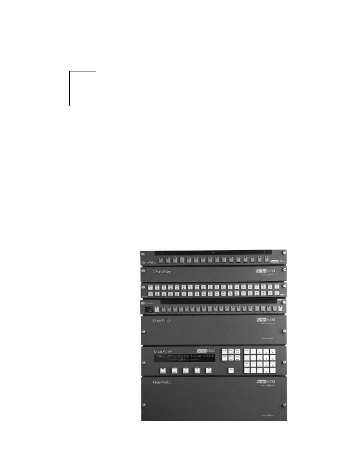
The Series 6000 Compact Signal Management System has been designed
with the smaller routing switcher applications in mind. In sizes of 1RU,
2RU, or 3RU, it accommodates matrices from 16 x 4 to 32 x 32.
With the Series 6000, you can mix serial composite and component digital
video in the same frame. And you can combine routing matrices of
different formats to build a multiformat system that meets your exact
needs.
This section describes the features of the Series 6000 and how to apply them
in your own particular application. A Series 6000 system is illustrated in
Figure 1-1.
3529-00
Figure 1-1. Series 6000 Compact Signal Management System
1-1
Page 19

Section 1 — Introduction
The System
The Series 6000 system comprises video, audio and control level (RS422)
routers, all based on the standard block size of 16 inputs to 16 outputs.
Video and audio matrices are housed in separate rack-mount frames
complete with power supply and microprocessor control.
Units are stacked together to provide multiple levels. For example, a
system could be provided with serial digital, composite video, three levels
of component video, four levels of audio, time code and RS422.
Remote control panels are usually supplied as part of a system and these
are connected back to the frames by a single coax
each of the frames and remote control panels in the system.
Quick-Link Bus through
The Frame
The frames are of solid construction and house plug-in modules. The main
router modules — video, audio or control level — are located on the left-
hand side and the power supply module(s) on the right.
The plug-in modules are positively locked in place to prevent them from
coming loose when installed in a mobile vehicle. Yet they can be easily
removed from the front of the frame by removing the front panel/local
control panel and releasing the modules held in place by special quick
release handles. The modules may be removed while the unit is under
power.
Analog Video Routing
The Series 6000 analog video matrix is suitable for wideband applications.
There are two 1RU frames, 16x4 and 16x16. The 3RU 32x32 matrix is built
from four 16x16 modules. These are organized in pairs so that each pair
provides 32x16 (32 inputs to 16 outputs). The pair of modules is bolted
together with connectors between them, and slides into the frame as a pair.
The upper module of the pair is fully loaded but the lower module contains
only the input and crosspoint stages. The upper module of the pair routes
inputs 1–16 and the lower module inputs 17–32.
1-2
Two of these 32x16 pairs of modules are used to build up a 32x32 matrix.
The upper pair of modules routes outputs 1–16 and the lower pair outputs
17–32.
In a single frame, there is no redundant power supply available. Dual
power supplies can be installed in the 3RU frame.
Page 20

Signal Path
Inputs
The Frame
The signal path has been designed to be as short as possible which reduces
the variations in path length between channels and maintains the overall
transparency through the router so important in broadcast applications
where multiple passes through equipment are required.
The video inputs are terminated in 75 Ω .
The main video module contains input buffers which have a high input
impedance to aid the return loss performance and an output capable of
driving the bank of crosspoint switches. The buffers can operate in two
modes: DC restored for use with composite signals or component signals
with sync present.
Crosspoints
Outputs
Alternatively the buffers can be set to operate in a DC coupled mode for
use with RGB or color difference signals which have no sync component.
The mode is selected by the user for each input by jumper links on the main
plug-in video module. This means that a single video matrix can handle a
mixture of composite and component inputs.
The DC restorer is a feedback sync tip restorer which prevents any
crushing of the sync signal.
The video crosspoint matrix consists of an array of 16x1 surface mount
assemblies. Sixteen of these assemblies are required to provide a matrix of
16x16 on each matrix module.
The video modules have output amplifiers built on thick film hybrid
circuits. They incorporate adjustment controls for gain and high frequency
response which are factory set.
1-3
Page 21

Section 1 — Introduction
Serial Digital Video Routing
The serial digital video matrix is capable of handling signals in the
following formats:
■
143Mb/s D2 NTSC composite
177Mb/s D2 PAL composite
■
270Mb/s D1 component
■
■
360Mb/s D1 component
Signal Path
The signal path is differential throughout to optimize waveform symmetry
and reduce crosstalk, which is important for transmission down long
cables.
Inputs
Crosspoints
The video inputs are terminated in 75 Ω .
The serial video signal passes through an input receiver circuit built onto a
plug-in SIMM socket so that extra channels can be added in the field. These
circuits provide equalization for losses, mainly at high frequencies, to serial
video signals which have travelled down long cables. This equalization is
varied automatically to suit the length and type of video cable used.
The circuit then locks an oscillator to re-clock the signal so that the correct
pulse widths and timings are regenerated. The circuit can be set to any of
the standards mentioned above, each input being programmed into the
setup of the system, either at the factory or from a PC using the SMS-6000
Configuration Editor. The phase-locked loop is designed to minimize the
jitter on the signal.
A single crosspoint chip selects the 16 inputs to the 16 outputs. It is rated to
operate to over 1Gb/s ensuring minimum degradation of edge speeds and
symmetry.
Outputs
1-4
The output amplifiers are designed to drive 75 Ω video cables.
Page 22

Analog Audio Routing
In the 1RU frame, the main analog audio matrix module provides a dual
channel 16x16 matrix. The 16x4 stereo audio is also a 1RU frame. This
matrix fits in a 1RU frame, which supports only a single power supply.
In the 2RU frame, two 16x16 matrix modules are used to make a 32x16
matrix. The main (lower) audio router module routes inputs 1–16 and the
submodule inputs 17–32. The output stages and their gain adjustments are
installed on the (upper) submodule for accessibility. Two 32x16 pairs of
modules are used to build up a 32x32 mono audio matrix. Dual power
supplies can be installed in this frame. Two frames are used for stereo.
Inputs
The inputs are electronically balanced. This provides a high common mode
rejection ratio over a wide frequency range. Also, the balance is maintained
even if the source is floating. Some designs of electronically balanced
inputs cause the input lines to become unbalanced which can cause an
increase in crosstalk if the input cables are unscreened and run together
over long distances.
Analog Audio Routing
Crosspoints
Outputs
The input and output connectors are 50-pin D connectors.
The signals are filtered to reduce out-of-band high frequency signals and
re-balanced for internal use. The use of balanced circuitry throughout is of
immense value to the overall quality of performance. It improves virtually
every measured parameter by at least a factor of 2 compared to a similar
unbalanced design.
The matrix uses balanced 4x4 crosspoint chips. These exhibit excellent
signal path performance together with minimal crosstalk and switching
noise.
The only adjustment in the audio path is the output gain control. It offers a
±2dB gain control and is mainly provided to allow the gain to be adjusted
up slightly if the outputs are terminated in 600Ω. As this is now an unusual
practice, the insertion gain is factory set for unity into a load of 10kΩ.
1-5
Page 23

Section 1 — Introduction
AES/EBU Digital Audio Routing
The AES/EBU digital audio matrix is capable of handling signals in the
following formats:
■ 32KHz broadcast standard; NICAM
■ 44.1KHz compact disk
■ 48KHz AES/EBU standard
It can be supplied equipped for 16x16 or 32x32.
Inputs
The audio inputs are transformer-coupled and normally terminated in
110Ω.
The audio signal passes through an input receiver circuit which locks an
oscillator to re-clock the signal so that the correct pulse widths and timings
are regenerated. The circuit automatically sets to any of the standards
mentioned above. The phase-locked loop is designed to minimize the jitter
on the signal.
Crosspoints
Outputs
Inputs 1–16 are installed on the main matrix module and Inputs 17–32 on
a submodule.
A single crosspoint chip has the capacity to switch 32 inputs to the 32
outputs.
The output drivers are normally arranged to drive 110Ω lines.
The module has the capability of 32 outputs, but for systems with 16
outputs it is installed with only 16 output stages.
1-6
Page 24

Data Routing
Inputs
Crosspoints
Data Routing
A solid state router is used mainly for machine control, such as to assign
VTRs to an edit controller. RS422 uses four wires with one pair used for the
transmit signal and the other pair for the receive, so the router handles both
a forward and a reverse signal path through the matrix. It can be supplied
equipped for 8x8 or 16x16.
The RS422 inputs are terminated in 110Ω. Inputs 1–8 are installed on the
main matrix module and Inputs 9–16 on a submodule.
Outputs
A single crosspoint chip has the capacity to switch 16 inputs to the 16
outputs.
The output drivers are designed to drive 110Ω lines.
The module has the capability of 16 outputs, but for systems with 8 outputs
it is installed with only 8 output stages.
1-7
Page 25

Section 1 — Introduction
Control System
The microprocessor-based control system activities are:
■ Read buttons and update displays on both local and remote control
■ Respond to data received through the computer port
■ Update the router crosspoint switches
■ Handle the communications between different switching levels such as
The system is shipped with a “basic” configuration. A customer may
change this configuration to fit their specific requirements using the
configuration software. This configuration is normally stored in an
NVRAM inside the Master unit (see below).
The control system maintains its status in a battery-backed memory so that
when the unit is powered down the router remembers its current settings
and on powering up again it switches the unit to those settings. The non-
volatile RAM which stores this information is located inside the Master
unit of the system (see below).
panels
audio and video frames
Configuration Switches
There are a number of switches provided which are used to configure the
system to suit your own requirements. They are briefly described below,
but for more details and a procedure for how to set them up, refer to
Section 2: Installation.
Address Switch
A rotary “hex” switch in each frame and panel determines its unique
address in the system. This ensures that each frame and each panel has a
different code allowing the communications down the coaxial Quick-Link
to distinguish different units. A frame and a panel can share the same code.
The firmware can tell from permanent links on the boards which ones are
panels and which ones are frames.
1-8
Page 26

Control System
DIP Switches
There are four positions available on the DIP switch at the front of the
crosspoint modules. They operate in the same way for video and audio
crosspoint modules. Refer toTable 1-1 for the correct settings of the DIP
switch for either a master frame or a slave frame.
Table 1-1. Dip Switch Settings
DIP Switch Position Master Frame Slave Frame
1 UP UP
2DOWNUP
3DOWN UP
4UPUP
Control Bus Quick-Link
The Quick-Link used to interconnect the panels and frames uses a single
coaxial cable.
The Quick-Link is daisy-chained from one panel to the next and between
the frames. Messages are sent by injecting signal currents onto the link, to
be received by all the other panels or frames on the line. The link is
terminated with 75Ω at both ends.
A hex switch in each frame and panel sets the identity of each so that they
are correctly addressed by the control system. Up to 16 panels and 16
frames can be supported. Local control panels can be optionally mounted
on any 1RU frame (except 32 x 32 AES/EBU 1RU frame) to increase total
panel count to 32.
Two BNC sockets are provided on the frames fed from a single driver/
receiver. Thus short lengths of coax cable can be used to interconnect the
frames in a multi-frame system by looping through the frames. The panels
use one BNC connector and a T-piece to tap off the Quick-Link into the
panels. In this way a panel can be removed from service without the Quick-
Link being interrupted, even momentarily.
A total run of 500 meters (1641 ft.) of video cable can be used between
panels and the frames.
As part of the fault diagnosis system, detectors are provided in the frame
and panels to identify faults. If either one or both terminations has been
omitted or if the cable is too loose and risks communication errors then
these are highlighted by the control system with LEDs on the front of the
router module. These features are very useful at installation as it enables
the cable and its terminations to be verified.
1-9
Page 27

Section 1 — Introduction
Computer Ports
The computer port is used to connect to dumb terminals or to computers.
An IBM 80486, or higher, is recommended. At a minimum the users should
have the following:
■ IBM PC, PS/2 or 100% compatible
■ MS–Dos 3.3 or higher
■ 4MB RAM
■ 1 MB hard disk required
■ RS232 Serial Port
■ MS or compatible mouse
NOTE:
Run setup from DOS or there may not be sufficient memory to use the text
editor.
Serial Interface SMS–CSI
The Serial Interface can be used to enable a computer to be used with the
SMS-6000 Configuration Editor, or for remote control applications. It is an
option which is installed in the master frame.
Normally this option is installed at the factory prior to shipment. The
instructions below are for use if the option is supplied after shipment of the
main unit.
Installation
Remove the serial interface submodule from its packing. Check that its
pins are straight and undamaged. Set the jumpers on the Serial Interface
module. Follow the steps listed below.
Installation in Matrix Frames
1-10
1. Unplug the power.
2. Unscrew the front panel retaining screws. The blank panel can then be
removed. If a local control panel is mounted on the frame, disconnect
the ribbon cables from the front of the matrix module. Release the
retaining latches to withdraw the ribbon cable plugs and remove the
panel.
3. Use the release catches at the sides of the matrix module to release the
locks which hold the module in place. Then pull the catches outwards
to eject the module from its edge connectors.
Page 28
Serial Interface SMS–CSI
4. Remove the module and carefully place it on an anti-static surface.
5. Position the serial interface submodule over the matrix module using
the hole as a guide.
CAUTION
If the module is positioned incorrectly, damage may result to both assemblies.
6. Line the pins over the sockets and push the submodule down gently
and evenly so that all pins enter the sockets at the same time. Push
firmly to completely seat the submodule.
7. Reinstall the matrix module in the frame. Press the module in firmly to
seat it in its connector.
8. Reconnect the power.
Setup
RS422 or RS232 Mode
This is the hardware standard supported by the Computer Port. Set it to
suit the computer or terminal to be used by moving jumper links on the
Serial Interface module. Position the module so that the large chip is top
left.
Depending on which Serial Interface module you have the jumper settings
are as follows:
Set jumpers LK1-5 toward the front of the frame for RS422
toward the rear of the frame for RS232
or
Set the single jumper to the left for RS232 or to the right for RS422 as
indicated on the module
162106-00
• • •
232 422
• • • • •
• • • • •
• • • • •
162180-00
RS422
Figure 1-2. Serial Interface Jumper Setiings
RS232
1-11
Page 29

Section 1 — Introduction
Baud Rate and Data Format
The emulation mode used by the computer interface is set to VT100 or
compatible at the factory. The baud rate is set to 9600 with 8 data bits, 1 stop
bit, and no parity.
External Connections
The wiring of the connectors is different for RS232 and RS422.
The frame has been built to minimize RF emissions. It is important you use
tin and dimple D type connectors with metallized shells connected to the
shield of external cables in order to achieve low RF emissions from this
equipment. The shells are fixed with screwlocks with 4–40 UNC threads.
The RS232 Interface Cable
The interface connector on the router is a 9-pin D socket. The cable between
the PC and the router only needs to use TX, RX, and GND as shown in
Table 1-2.
Table 1-2. RS232 Cable Connections
Computer
9-Pin D
Socket
2 (RXD) 7 (TXD) 3 (RXD) 7 (TXD)
3 (TXD) 3 (RXD) 2 (TXD) TX–3 (RXD)
5 (GND) 6 (GND) 7 (GND) 6 (GND)
NOTES:
The SMS-6000 Configuration Editor requires an RS232 Connection.
Router
9-Pin D Plug
Computer
25-Pin D
Socket
Router
9-Pin D Plug
Remote control can be performed with either the RS232 or the RS422 format.
1-12
Page 30

Serial Interface SMS–CSI
The interface connector on the router is a D9 socket using Table 1-3 pinouts.
Table 1-3. RS232 and RS422 Cable Connections
RS232 RS422
Pin # Signal Pin # Signal
1 GND 1 GND
2 RTS 2 TX–
3 TXD 3 RX+
4 0V 4 RX 0V
5 24V High 5 24V High
6 0V 6 TX 0V
7 TXD 7 TX+
8 CTS 8 RX–
9 not used 9 not used
Table 1-4 pinout is normally used on personal computers, but check your
own computer's documentation.
Table 1-4. Personal Computer Cable Connections
9-Pin D Connector 25-Pin D Connector
Pin # Signal Pin # Signal
1 DCD 2 TXD
2 RXD 3 RXD
3 TXD 4 RTS
4 DTR 5 CTS
5 GND 6 DSR
6 DSR 7 GND
7 RTS 8 DCD
8 CTS 20 DTR
9RI 22RI
1-13
Page 31

Section 1 — Introduction
Local Control Panel SMS–CMXY-LP
This panel is available only on 1RU frames, (except the 32 x 32 AES/EBU
1RU frame). The design of the panel is similar to that of the SMS–CMXY
remote panel.
The SMS–CMXY-LP panel can be installed to the front of the frame. This
saves an extra rack unit when a panel is required adjacent to the rack,
perhaps for engineering use and, because it shares the electronics
hardware in the main unit, it is of lower cost than the SMS–CMXY remote
panel.
This panel has the capability to control all 16 inputs, 16 outputs and four
signal levels, and has a lock feature to protect established routes. Refer to
Section 4: Control Panels and Operation for details of how it is used.
1-14
Page 32

Power System
Power System
1RU frame, can have only a single power supply, whereas 2 or 3RU frames
have the option of dual supplies to protect against the failure of one of the
supplies or, the loss of incoming AC power on one power bus. There are
two AC power connectors so that a backup supply can be fed from a
completely separate power lead, thereby offering maximum protection
against loss of power. The AC connectors are located on the rear panel and
incorporate a fuse and adjacent voltage selector for convenience during
installation.
A traditional transformer system in the rear of the matrix frame is used to
step down the mains voltage to around 20 volts AC. On the plug-in power
module the AC voltages are rectified and smoothed to produce raw DC
rails of 20–30 volts. Low voltage switching techniques are then used to
convert the raw DC into the smooth DC voltages used on the router
modules. This method has the benefit of low heat generation without the
high stress of mains voltages on the components found in traditional
switch-mode designs. These features both contribute to high reliability.
CAUTION
Different modules need different power rails and these rails are selected by jumper
links on the power module. If the incorrect module is plugged into a frame, then
permanent damage may be caused to the main module. Some modules are
installed with a linearly regulated third (+12V) rail to drive a cooling fan.
A standby switch at the front of each Power Supply (PS) module enables
the DC power to be switched off but does not disconnect the mains power.
Cooling Fan - 1RU frame
On some frames a cooling fan installed on the right-hand side of the frame
draws cool air from the side and expels it through the vents along the lefthand side of the frame. The Power Supply module provides the 12V DC
supply for this purpose, which is not switched by the standby switch on the
PS module so the fan will always run when the power cord is plugged in.
Cooling Fan - 3RU frame
The cooling fan installed in the rear of the frame draws cool air from the
rear and expels it through the vents along the left-hand side of the frame.
It is powered from both power modules, so that if either fails then it
continues to run. The Power module provides the 12V DC supply for this
purpose, which is not switched by the standby switch on the PS module so
the fan will always run when the power cord is plugged in.
1-15
Page 33

Section 1 — Introduction
Ground and Power Fail Alarms
A terminal strip is provided on some units to select how the system is
grounded.
Separate connections are provided on the rear of audio frames for:
■ TECH 0V Internal technical 0V
■ GND To ground pin of power connector and to the
■ O/P SCREENS The 16 shield pins on the two Output connectors are
■ I/P SCREENS Connection to the shield pins of the two Input
CAUTION
The TECH 0V must be connected to an earth ground in order to operate the
equipment safely.
external metalwork
connected together and to this pin
connectors
The equipment is shipped from the factory with the TECH 0V and GND
linked together to ensure that the electronics hardware is properly
grounded.
The input and output shields terminals are provided to avoid the problems
of ground loops caused by differences in the ground potentials on the
shields (screens) of the input cables and the output cables. It is common to
connect the O/P SCREENS to GND at the driving end, but some installers
prefer to connect I/P SCREENS to GND instead. However it is inadvisable
to connect both sets of shields to GND.
On the 3RU video frame the terminal strip has the following connections:
■ TECH 0V Internal technical 0V
■ GND To ground pin of power connector and to the
external metalwork
■ POWER FAIL Pair of contacts held closed, so long as both power
supplies are installed, switched on and working
CAUTION
The TECH 0V must be connected to an earth in order to operate the equipment
safely.
1-16
The equipment is shipped from the factory with the TECH 0V and GND
linked together to ensure that the electronics hardware is properly
grounded.
Page 34

Remote Control Panels
Refer to Section 4: Control Panels for details of the control panels and their
operation. The following points apply to most panels.
General Points
Remote panels are used to indicate current crosspoint connections and to
make new selections at various locations to suit the user. Most panels are
connected to the frame via the Quick-Link coaxial link. The identity of each
panel is determined by the unique setting of a rotary hex switch in each
panel.
Each panel is set up to operate in a particular way by the system
configuration located in the master frame of the system. This determines, for
instance, which destinations can be controlled from each panel. The rotary
hex switch mentioned above serves to route the correct setup to each panel.
Remote Control Panels
Panels are powered from a local 115V/230V mains supply.
1-17
Page 35

Section 1 — Introduction
Specifications
Specifications are subject to change without prior notice.
Video Inputs
Nominal Signal Level
Maximum Signal Level
Impedance 75Ω terminating
Table 1-5. Analog Video Specifications
Video signal
Sync pulses
Subcarrier
DC restored inputs video signal
DC restored inputs sync pulses
DC coupled inputs video or Subcarrier
1V p-p
2V p-p
1V p-p
+6dB
2.5V p-p
±–0.7V
Return loss to 5.5 MHz 40dB
DC on input (DC restored) ±3V
Video Outputs
Impedance 75Ω
Return loss to 5.5 MHz 35dB
DC on output
†
±50mV
Insertion Gain
Insertion gain ±0.1dB
Gain spread between inputs ±0.05dB
Adjustment range ±0.5dB
Linear Distortion
HF response 15KHz to 5.5MHz
5.5 to 10MHz
10MHz to 30MHz
above 30MHz
±0.1dB
±0.2dB
+0.5, –1.0dB
smooth roll off
1-18
HF adjustment at subcarrier ±0.5dB
LF response, tilt at 50/60 Hz ±0.5%
2T pulse 0.25%K
2T pulse/bar ratio 0.25%K
Page 36

Table 1-5. Analog Video Specifications - (continued)
Linear Distortion (continued)
2T bar slope 0.25%K
Y-C gain inequality ±0.5%
Y-C delay inequality ±5ns
Non-Linear Distortion
Differential gain (10–90% APL) 0.15%
Specifications
Differential phase (10–90%APL) 0.15
Luminance non-linearity 0.2%
C-Y intermodulation 0.5%
Dynamic gain (Y, C, syncs) 0.5%
Transient gain (Y, C, syncs) 1%
o
Propagation Delay
Path length 13ns typical
Timing spread at 4.43MHz
one output
all outputs
±1°
±2°
Crosstalk/Noise
Crosstalk, to 5.5MHz worst case 60dB, 30MHz version
Noise to 5.5MHz –70dB rms
Video spikes at switching ±20mV
Switching Reference
Signal level 1V p-p ±3dB
1–4V pulses
Impedance 75Ω looping
DC on input ±1V
Switching occurs on lines 7/320 to 11/324, field or frame rate,
jumper selectable
1-19
Page 37

Section 1 — Introduction
Power
Table 1-5. Analog Video Specifications - (continued)
Rear panel voltage selector 90–132V 50/60Hz
Power consumption (1RI) 25 watts
Power consumption (3RU) 90 watts
Connector (1RU) IEC with retaining latch
Connector (3RU) IEC with retaining latch, backup optional
Power fail alarm output
Both Power Supplies good
One Power Supply failed or absent
Technical & chassis ground (3RU only) screw terminals
180–264V 50/60Hz
screw terminals
closing relay contact, rated at 250mA, 50V
open relay contact
Control
Quick-Link to remote panels 75Ω video cable
Computer port RS232/RS422 D9 socket
500M (1641 ft) max length
Mechanical
Height 1RU, 1.75 in (44mm)
Width 19 in rack mount
Depth 19.75 in (500mm)
Weight 1RU, 13.5 lb (6Kg)
3RU, 3.5 in (133mm)
2RU, 26.5 lb (12Kg)
Environmental
Ambient T emper ature
Operating and storage
Specification maintained
Humidity 10–90% non-condensing
† In the DC coupled mode the DC on the output is specified with the input terminated in 75Ω. In
the DC restored mode the specification refers to the black level when the sync amplitude is
300mV.
0–40°C
20–30°C
1-20
Page 38

Specifications
Table 1-6. Analog Audio Specifications
Audio Inputs
Signal level 0dBu nominal, +24dBu maximum
Impedance 20KΩ
Common Mode Rejection
20Hz to 3KHz
3KHz to 20KHz
Common Mode Level +30dBu maximum with no signal
Audio Outputs
Impedance 40Ω balanced
DC on output ±50mV
–80dB, –100dB typical
–60dB, –70dB typical
Signal Path
Impedance ±0.1dB
Frequency Response 20Hz to 20KHz
to 150KHz
Relative delay between two routes 1 µs
Total harmonic distortion
–10dBu to +20dBu, 20Hz to 20KHz 0.02%, 0.01% typical
Crosstalk 20Hz to 20KHz –90dB worst case, –105dB typical
Noise 20Hz to 20KHz –85dBu rms unweighted, –90dBu typical
±0.25dB
3dB
Power
Rear panel voltage selector 90–132V 50/60H
Power consumption 1RU, 25 watts
Connector 1RU, IEC with retaining latch
180–264V 50/60Hz
2RU, 50 watts
2RU, IEC with retaining latch, backup
optional
Power fail alarm output
Both Power Supplies good
Power Supply failed or absent
Technical and chassis ground,
cable shields
screw terminals
closing relay contact, rated at 250mA, 50V
open relay contact
screw terminals
1-21
Page 39

Section 1 — Introduction
Control
Table 1-6. Analog Audio Specifications - (continued)
Quick-Link to remote panels 75Ω video cable
Computer port RS232/RS422 D9 socket
500M (1641 ft) max length
Mechanical
Height 1RU, 1.75 in (44mm)
Width 19 in rack mount
Depth 19.75 in (500mm)
Audio Connectors 50-pin D connector
Weight 1RU, 13.5 lb (6Kg)
2RU, 3.5 in (88mm)
2RU, 22.25 lb (10Kg)
Environmental
Ambient T emper ature
Operating and storage
Specification maintained
0–40°C
20–30°C
Humidity 10–90% non-condensing
1-22
Page 40

Table 1-7. Serial Digital Video Specifications
Video Input
Signal level 800mV p-p, nominal
Impedance 75Ω terminating
Return loss, 5 to 270 MHz 15dB, 16dB typical
DC on input ±3V
Specifications
Cable equalization at 270Mb/s 250M (820.25 ft), 300M (984.5 ft) typical
Belden 8281, PSF 1/2
150M (492.25 ft), 200M (656.25) typical
PSF 1/3
Video Outputs
Signal level 800mV ±–10%
Impedance 75Ω
Return loss, 5 to 270MHz 15dB
DC offset ±0.5V
Rise/fall time into 75Ω resistive load,
20 to 80%
Jitter 500ps p-p max
0.6 to 0.9ns
Switching Reference
Signal level 1V p-p ±–3dB or 1–4V pulses
Impedance 75Ω looping
DC on input ±1V
Switching occurs on lines 7/320 to 11/324, field or frame rate, link
selectable
1-23
Page 41

Section 1 — Introduction
Power
Table 1-7. Serial Digital Video Specifications - (continued)
Rear panel voltage selector 90–132V 50/60H
Power consumption 1RU, 30 watts
Connector 1RU, IEC with retaining latch
Power fail alarm output
Both power supplies good
One power supply failed or absent
Technical and chassis ground screw terminals
180–264V 50/60Hz
3RU, 60 watts
2RU, IEC with retaining latch, backup
optional
screw terminals
closing relay contact, rated at 250mA, 50V
open relay contact
Control
Quick-Link to remote panels 75Ω video cable
Computer port RS232/RS422 D9 socket
500M (1641 ft) max length
Mechanical
Height 1RU, 1.75 in (44mm)
3RU, 3.5 in (133mm)
Width 19 in rack mount
Depth 19.75 in (500mm)
Weight 1RU, 13.5 lb (6Kg)
3RU, 22.25 lb (10Kg)
Environmental
Ambient T emper ature
Operating and storage
Specification maintained
Fan-cooled by drawing cool air from right-hand side (1RU) or rear (3RU) of frame and
exhausting the warm air from the left-hand side.
Humidity 10–90% non-condensing
0–40°C
10–30°C
1-24
Page 42

Specifications
Table 1-8. AES/EBU Digital Audio Specifications
VAES/EBU Input
Sample rates 32, 44.1, 48KHz
Impedance 10Ω ±20% transformer coupled
Signal level 0.2–7V p-p
DC on input ±50V
AES/EBU Outputs
Rise/fall times into 110Ω resistive load 5–30ns
Jitter <20ns
Signal Level 2–7V p-p
Impedance 110Ω transformer coupled
DC isolation ±50V
Power
Rear panel voltage selector 90–132V 50/60Hz
Power consumption 15 watts
Connector (1RU frame) IEC with retaining latch
Connector (2RU frame only) IEC with retaining latch, backup optional
Power fail alarm output (2RU frame only)
Both power supplies good
One power supply failed or absent
Technical and chassis ground, cable
shields(screens)
180–264V 50/60Hz
screw terminals
closing relay contact, rated at 250mA, 50V
open relay contact
screw terminals
1-25
Page 43

Section 1 — Introduction
Control
Table 1-8. AES/EBU Digital Audio Specifications - (continued)
Quick-Link to remote panels 75Ω video cable
Computer port RS232/RS422 D9 socket
500M (1641 ft) max length
Mechanical
Height 1RU, 1.75 in (44mm)
Width 19 in rack mount
Depth 19.75 in (500mm)
Weight 13.5 lb (6Kg)
Audio Connectors 50-pin D connector
Environmental
Ambient T emper ature
Operating and storage
Specification maintained
Humidity 10–90% non-condensing
0–40°C
10–30°C
1-26
Page 44

Table 1-9. RS422 Control Level Specifications
RS422 Signal Input
Impedance 10Ω
Maximum baud rate 1Mbaud
RS422 Signal Outputs
Signal Level 2–7V p-p
Impedance 110Ω
Rise/fall times into 110Ω resistive load 5–30ns
Power
Specifications
Rear panel voltage selector 90–132V 50/60H
Power consumption 15 watts
Connector IEC with retaining latch
180–264V 50/60Hz
Control
Quick-Link to remote panels 75Ω video cable
Computer port RS232/RS422 D9 socket
500M (1641 ft) max length
Mechanical
Height 2RU, 3.5 in (88mm)
Width 19 in rack mount
Depth 19.75 in (500mm)
Weight 22.25 lb (10Kg)
Environmental
Ambient T emper ature
Operating and storage
Specification maintained
Humidity 10–90% non-condensing
0–40°C
20–30°C
1-27
Page 45

Section 1 — Introduction
1-28
Page 46

2
Introduction
Unpacking
Installation
This section describes how to install your Series 6000. The system has been
designed with the aim of being quick and simple to install.
Remove the equipment carefully from the boxes and check against the
Packing List supplied with each unit. This shows what items have been
shipped against your order and includes all options. Any error should be
reported immediately. After you have unpacked the equipment, please
save all the packing material as this could be useful in the future if the unit
needs to be returned for maintenance.
Check each item supplied for transit damage. Any damage should be
reported in detail. You must state the serial number of the unit (to be found
on the rear, side or base of each unit).
Locate the power cords suitable for your country and verify that the
equipment has been set to the correct mains (line) voltage.
NOTE:
Instructions are to be found later in this section on how to change the
voltage.
Remote panels are mains powered and must also be checked.
2-1
Page 47

Section 2 — Installation
Physical Installation
Remote Panels
Remote control panels are designed to fit into standard 19 inch equipment
racks. Panels can be mounted at any angle.
Panels are designed to fit into horizontal desks with a minimum of depth
to allow for knee room. Refer to Section 4: Control Panels for the depth of
the panels.
Equipment Frames
All frames are designed to be mounted in standard 19 inch equipment
racks. Standard panels are 5.15 in (130mm) deep plus connectors.
When preparing for installation keep in mind that the modules are
plugged in from the front and extra space is required for the modules to
mount on an extender module. Allow at least 31.5 in. (800mm) clearance at
the front for maintenance.
The depth of the frame is 19 in. (485mm) plus connectors from the front of
the equipment rack. In addition allowance must be made for the numbers
of cables to be installed at the rear of the frame.
Cooling
Power dissipation in most frames is relatively low and cooling is achieved
by natural convection through the sides of the frame. However the 1RU
Serial Digital Video Router is fan cooled, drawing cool air in from the righthand side of the frame and expelling it at the left-hand side of the frame.
It is important that the ventilation slots in the lid of the this unit are not
obstructed; it is perfectly acceptable to install a control panel or another
shallow unit immediately above the unit but not another frame.
In the interests of long term reliability it is advisable, where possible, to
leave a 1RU gap or to fit a unit with a depth of less than .78 in (200 mm)
above every fourth frame.
The 3RU Video Router and 3RU Serial Digital Video Router are also fan
cooled, drawing cool air in from the rear of the frame and expelling it at the
left-hand side of the frame.
In all cases it is important to keep the apertures clear of obstructions eg
cables.
2-2
If a 1RU frame is fitted into a mobile vehicle, it is strongly recommended
that some type of rear support should b e used to prevent bending. The
support bar should be designed to fitthe depth of the equipment racks.
Page 48

Electrical Connections
Refer toFigure 2-1 through Figure 2-6 on page 12 and page 13 for the rear
view of the frames when making the electrical connections to each frame.
Video Inputs and Outputs
These connections are made using standard 75Ω video coaxial cable. A
high quality cable such as Belden 8281, PSF1/2 or PSF1/3 or equivalents
should be used for optimum performance. It is both important and good
practice that cables are properly supported and not hanging on the
connectors as this can put unnecessary stress on the connectors and
possibly reduce their working life.
The video inputs are terminated in 75Ω within the equipment. The video
outputs are single 75Ω outputs.
Electrical Connections
Video Reference
The Ref input is a looping input. Any video signal with standard syncs may
be used as a reference signal to determine when crosspoints are switched
during vertical (picture) blanking. While a burst is not required the use of
color black is the most commonly available signal and is preferred. This
can be looped through into a video input of the unit.
Mixed sync pulses of 2V amplitude may also be used. 4V pulses can be
used but a modification is required to the main video router module and
involves the addition of a single 4.7K 5% resistor, labeled R126.
If no reference signal is connected then the unit will switch at random
intervals at a rate of about 40Hz.
NOTE:
plug must be fitted on the unused connector, otherwise the level on the line will be
twice that expected and may cause incorrect operation of equipment attached to
this line.
If one of the looping input connectors is not used then a 75Ω terminator
2-3
Page 49

Section 2 — Installation
Audio Inputs and Outputs
The connections of the audio signals to the equipment are made using
50-pin connectors. One connector is used for each 16 inputs and another for
each 16 outputs. The same type or polarity of connector is used for inputs
and outputs.
The 16x4 and 16x16 stereo audio routers are 1RU high. One pair of
connectors is for the Channel I inputs and outputs (that is, mono operation)
and a second pair for the Channel II inputs and outputs for the second
(stereo) audio level.
The 32x32 mono audio analog matrix is a 2RU frame. Two frames are used
for stereo. One pair of connectors is provided for Inputs 1–16 and 17–32
and a second pair labeled “Outputs 1–16 B” and “Outputs 17–32 B” for
Outputs 1–16 and 17–32. The connectors labeled “Outputs 1–16 A” and
“Outputs 17–32 A” are reserved for special applications.
The 32x32 AES/EBU digital audio frame outputs are assigned to rear
connectors as follows:
Outputs 1-16: “Outputs 1-16A”
Outputs 17-32: “Outputs 1-16B”
The mating halves of these connectors are plug types and available as
options. They are not supplied as standard because many customers wish
to buy their connectors in bulk and prepare the cables in advance of the
equipment being shipped.
Each connector has three pins for each signal: signal hot (+), signal cold
(–) and shield (screen). The same pattern of wiring is used on all four
connectors, (Input 1 is wired the same as Output 1). All the connectors on
the rear of the frames are sockets. Table 2-1 on page 5 and Table 2-1 on
page 6 list the connector pinouts for these cables.
The input and output cable screen (shield) pins are wired together inside
the frame and to a pair of screw terminals on the rear of the frame. This
enables the installer to choose whether the input and/or output signal
cable shields are grounded or not. It is sound audio practice not to ground
the shields at both ends, as sometimes hum can be introduced due to
ground potential differences.
2-4
Page 50

Electrical Connections
For the correct audio input pinouts, refer to Table 2-1.
Table 2-1. Audio Input Pinouts
Pin Signal Pin Signal Pin Signal
1 Gnd 34 Src 1+
2 Src 2+ 18 Src 1– 35 Gnd
3 Gnd 19 Src 2– 36 Src 3+
4 Src 4+ 20 Src 3– 37 Gnd
5 Gnd 21 Src 4– 38 Src 5+
6 Src 6+ 22 Src 5– 39 Gnd
7 Gnd 23 Src 6– 40 Src 7+
8 Src 8+ 24 Src 7– 41 Gnd
9 Gnd 25 Src 8– 42 Src 9+
10 Src 10+ 26 Src 9– 43 Gnd
11 Gnd 27 Src 10– 44 Src 11+
12 Src 12+ 28 Src 11– 45 Gnd
13 Gnd 29 Src 12– 46 Src 13+
14 Src 14+ 30 Src 13– 47 Gnd
15 Gnd 31 Src 14– 48 Src 15+
16 Src 16+ 32 Src 15– 49 Gnd
17 Gnd 33 Src 16– 50 Gnd
2-5
Page 51

Section 2 — Installation
For the correct audio output pinouts, refer to Table 2-2.
Table 2-2. Audio Outputs Pinouts
Pin Signal Pin Signal Pin Signal
1 Gnd 34 Dst 1+
2 Dst 2+ 18 Dst 1– 35 Gnd
3 Gnd 19 Dst 2– 36 Dst 3+
4 Dst 4+ 20 Dst 3– 37 Gnd
5 Gnd 21 Dst 4– 38 Dst 5+
6 Dst 6+ 22 Dst 5– 39 Gnd
7 Gnd 23 Dst 6– 40 Dst 7+
8 Dst 8+ 24 Dst 7– 41 Gnd
9 Gnd 25 Dst 8– 42 Dst 9+
10 Dst 10+ 26 Dst 9– 43 Gnd
11 Gnd 27 Dst 10– 44 Dst 11+
12 Dst 12+ 28 Dst 11– 45 Gnd
13 Gnd 29 Dst 12– 46 Dst 13+
14 Dst 14+ 30 Dst 13– 47 Gnd
15 Gnd 31 Dst 14– 48 Dst 15+
16 Dst 16+ 32 Dst 15– 49 Gnd
17 Gnd 33 Dst 16– 50 Gnd
2-6
Page 52

Data Matrix
Electrical Connections
For the correct pinouts for the Data Matrix refer to Table 2-3. Wiring of the
signal conforms to RS422 standard. Mating connectors are available as
options, (SMS-CDRC). Ensure that the cable screen is grounded to
minimize RFI emissions.
Table 2-3. Data Matrix Pinouts
Input Pins Signal Output Pins Signal
1 GND 1 GND
2 TXA 2 RXA
3 RXB 3 TXB
4 RX 0V 4 TX 0V
Control — Quick-Link
All the frames and remote control panels are connected by a single coaxial
link called Quick-Link. This link uses standard 75Ω coaxial cable daisychained from frame to frame and panel to panel. Each end of the link must
be terminated in 75Ω. A pair of connectors is fitted to the frames and the
link looped through them; but just one connector is fitted on the panels and
a T-connector is needed to tap off the Quick-Link. In this way a panel can
be removed from service and replaced without disrupting the link, even
temporarily.
This daisy chain method ensures the best transmission quality of the
control signals down the cable. Short cuts which might save cable, such as
running stubs to some panels are not recommended as this may under
certain circumstances cause data errors. The maximum cable stub length is
19.75 in (500mm). The maximum cable length is shown in the Specification
in Section 1: Introduction of this manual
5 Not Used 5 Not Used
6 TX 0V 6 RX 0V
7 TXB 7 RXB
8 RXA 8 TXA
9 GND 9 GND
The system can support up to 16 panels and 16 frames. Each unit connected
to the Quick-Link has its own ident switch which is set up as part of the
system setup. The extra Quick-Link connectors on the 3RU Video frame are
not currently supported.
2-7
Page 53

Section 2 — Installation
Remote Control
RS232/422 Computer Port
The connectors (9-pin D-type sockets) for the computer ports are fitted on
the rear of each frame. some Most units have just one connector, but the
3RU video and serial frames have four connectors of which only one, Serial
4 port, is supported at present.
Joystick Override
Joystick or camera microswitch override is provided as a standard feature
on most control panels and is accessed on the PARALLEL port. For the
correct pinouts for the Joystick Override refer to Table 2-4.
NOTE:
The mating connector is a 9-pin D-type socket, use a tin and dimple type
with a grounded metal shell to prevent RFI emission from the equipment.
Table 2-4. Joystick Override Pinouts
Input Pins Signal
1 Camera 1
2 Camera 2
3 Camera 3
4 Camera 4
5 Camera 5
6 Camera 6
7 Camera 7
8 Camera 8
2-8
9 GND
By default the eight cameras are assigned to be the first eight inputs of the
matrix, but it is possible for them to be mapped to any input using the SMS6000 Configuration Editor.
Page 54

Electrical Connections
Power
CAUTION
IEC connectors are used to supply power to frames and panels alike. The ground
pin of each connector must be connected to a solid ground to ensure proper
grounding of the metalwork.
Equipment is often supplied with a power cord suitable for wiring into a
plug of the user's choice. Please wire the plug using the color code below:
■ Brown Live (Line or Phase)
■ Blue Neutral (Return)
■ Green/Yellow Earth (Ground)
WARNING
Some of the frames are fitted with screw terminals so that the CHASSIS and
TECHNICAL ground can be wired to different ground points. The equipment
is shipped with a wire link fitted between these terminals. If the link is
disconnected then it is imperative for personal safety that a proper ground
connection is established.
2-9
Page 55

Section 2 — Installation
Setting the Power Line Voltage in the Frames
The voltage must be checked and if necessary set prior to inserting the
power cord.
The 220V (or 230V) setting is suitable for both 220V and 240V countries.
The 110V (or 115V) setting is suitable for 100V and 120V countries. Refer to
the technical specifications in Section 1: Introduction for the voltage
ranges permitted.
1. Remove the power cord(s).
2. Use a small screwdriver to loosen the voltage selector/fuse holder by
prying from above.
3. Pull out the fuse drawer. The main fuse is clearly visible, (there may
also be a spare).
4. Some equipment uses a voltage selector in which a single voltage is
visible through a small window, in which case follow step 4a below.
Other equipment uses a voltage selector in which two voltages are
visible, in which case follow step 4b below.
a. Remove the voltage selector insert from the main fuseholder and
select the required voltage setting. Replace it in the fuseholder. Fit
the correct fuse and replace the fuseholder, pushing until it snaps
into place.
b. Rotate the drawer so that the correct power line voltage can be read
(and the incorrect is upside down). Fit the correct fuse and replace
the fuseholder, pushing until it snaps into place.
2-10
5. Plug the power cord into the equipment.
6. Repeat the procedure if there is a backup supply.
Page 56

Setting the Power Line Voltage in the Panels
Some panels are fitted with power connectors equipped with voltage
selectors, labeled 115V/230V; if so follow the procedure above for the
frames. If not follow the procedure below.
WARNING
Check that the factory voltage setting are suitable for your country prior to
inserting the power cord. The top cover must be removed and a soldering
iron used in order to alter the power line voltage setting if necessary. As it
affects personal safety this should be performed b y qualified personnel only .
1. Remove the power cord(s).
2. Remove the top cover from the unit by removing the screws.
3. Pull off the shroud and inspect the transformer for the correct wiring:
Electrical Connections
a. For 110V–120V, the two 110V windings should be connected in
parallel.
b. For 220V–240V, the 110V and 130V winding should be
connected in series.
4. If not correct, unsolder the wires from the transformer primary
terminals and solder them as indicated in step 3.
5. Replace the top cover.
6. Use a small screwdriver to loosen the fuse holder by prying from
above. Pull out the fuse drawer. The fuse is clearly visible with a spare,
inside the drawer. Fit the correct fuse to suit the power line voltage in
your country. Replace the drawer.
7. Plug the power cord into the equipment.
2-11
Page 57
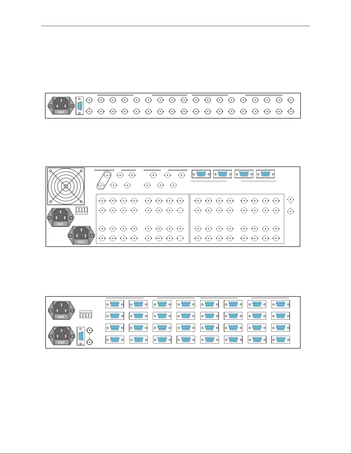
Section 2 — Installation
Frame and Parallel I/F Rear Views
Figure 2-1 through Figure 2-6 illustrate the rear view of the frames and
control panels.
POWER 2
COMPUTER
TECH
GND
OV
POWER 1
15 13 11 9 7 5 3 1 15 13 11 9 7 5 3 1
Q-LINK
16 14 12 10 8 6 4 2 16 14 12 10 8 6 4 2
VIDEO OUTPUTS
VIDEO INPUTS
Figure 2-1. 16x4 and 16x16 Video Frame
POWER
ALARM
MAIN
Q-LINK
1
3
4
2
121416 46810 2
111315 35791
VIDEO OUTPUTS
26283032 18202224
2531 29 27 23 21 19 17
UTILITY
3
5
6
4
1
2
43
SERIAL PORTS
121416 46810 2
111315 35791
VIDEO INPUTS
26283032 18202224
2531 29 27 23 21 19 17
Figure 2-2. 32x32 Analog Video Frame
21
REF
INPUT
REF
INPUT
3529-05
3529-09
2-12
POWER 2
POWER 1
COMPUTER
ALARM
POWER
Q-LINK
OUTPUTS INPUTS
913 15
13
1014 26
1115 37
1216 48
Figure 2-3. Data Matrix Frame
9
1014 26
1115 37
1216 48
15
3529-07
Page 58
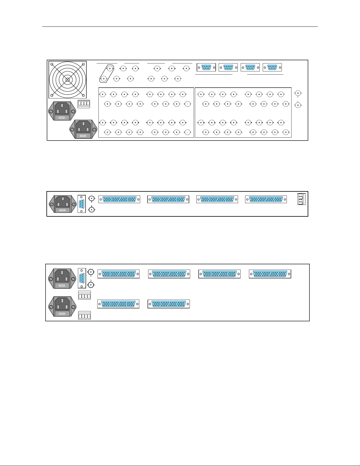
Electrical Connections
POWER 2
TECH
GND
OV
POWER 1
COMPUTER
POWER
ALARM
Q-LINK
MAIN
Q-LINK
1
3
4
2
121416 46810 2
111315 35791
VIDEO OUTPUTS
26283032 18202224
2531 29 27 23 21 19 17
UTILITY
3
5
6
4
1
2
Figure 2-4. 32x32 Serial Frame
OUTPUTS
CHANNEL I
OUTPUTS
CHANNEL II
Figure 2-5. 16x4 and 16x16 Audio Frame
43
INPUTS
CHANNEL I
SERIAL PORTS
121416 46810 2
111315 35791
VIDEO INPUTS
26283032 18202224
2531 29 27 23 21 19 17
21
INPUTS
CHANNEL II
TECH
OV
GND
O/P
SCREENS
I/P
SCREENS
3529-10
REF
INPUT
3529-06
POWER 2
POWER 1
COMPUTER
O/P
TECH
SCNS
0V
GND
Q-LINK
SCNS
ALARM
POWER
OUTPUTS 1-16 A OUTPUTS 1-16 B INPUTS 1-16 INPUTS 17-32
I/P
3529-08
OUTPUTS 17-32 A OUTPUTS 17-32 B
Figure 2-6. 32x32 Audio Frame
2-13
Page 59

Section 2 — Installation
Configuring the Frame
The system comes factory-configured but can be changed to suit your own
particular requirements. This sub–section describes how to do this for the
video and audio frames. The next sub –section covers the same processes
for the remote control panels.
NOTE:
The rotary hex and DIP switches are read only at power up or following a
RESET. If you make any changes you must press the RESET button so that the
new settings are acted upon.
Analog Video Matrix Module
Input Coupling Mode
Normally there are DC restorers on each video input. They restore the sync
tips (the lowest part of the signal) to a voltage of –300mV so that
irrespective of the DC or average picture level of the incoming signal the
DC of the black level on the output will be constant.
This is fine for composite video signals, but for component video signals,
Pr (V) and Pb (U) have the potential for signal content both above and
below black level. A DC restorer is not suitable for such signals and the
signal is DC coupled through the matrix. Each of the restorers can be
jumpered in or out of circuit. The jumpers are located near the edge
connector by the input capacitors and hybrids. For each input there are two
links.
With the module placed with the extractors levers nearest you and the edge
connectors furthest away:
2-14
Set the jumpers vertical for composite signals and horizontal for
component signals. A diagram on the module is located near to the
jumpers to clarify.
• •
• •
VERTICAL HORIZONTAL
• •
• •
Sometimes it is important to change the TV line in the vertical blanking
interval during which the routing switcher makes its crosspoint switches.
The analog video module provide this feature. Any line from 7/320 to 11/
324 may be selected using the three jumper links LK6, 7, 8. The diagram on
the circuit board shows the positions of the jumper links.
It is also possible to choose whether to permit switching on every TV field
or just on the first field of each picture. This can be important in certain
editing applications.
The factory settings for NTSC are line 10/273 and every field. For Pal they
are line 7/320 and every field.
Page 60

Serial Digital Video Matrix Module
Input Standards
The router is capable of handling up to four different input standards
(143Mbs, 177Mbs, 270Mbs, and 360Mbs) depending on which SIMMs are
installed. Current SIMMs (Quartz PCB) are capable of 270Mbs operation
only. Multi-standard SIMMs are under development. Each input can be set
to any of these standards which are programmed into the setup of the
system, either at the factory or from a PC using the configuration program.
TV Line Switching
Sometimes it is important to change the TV line in the vertical blanking
interval during which the routing switcher makes its crosspoint switches.
Any line from 7/320 to 11/324 may be selected using the three jumper links
LK6, 7, 8. The diagram on the circuit board shows the positions of the
jumper links.
Configuring the Frame
It is also possible to choose whether to permit switching on every TV field
or only on the first field of each picture. This can be important in certain
editing applications.
The factory settings for NTSC are line 10/273 and every field. For Pal they
are line 7/320 and every field.
2-15
Page 61

Section 2 — Installation
Frame Priority
One crosspoint matrix module in the system must be set as master and the
others as slaves. This is very important as there will not be proper
communications unless this rule is followed. The master frame contains
the configuration NVRAM and the non-volatile RAM to store the complete
matrix status.
The master and slave DIP switch settings are as follows:
Table 2-5. Dip Switch Settings
DIP Switch Position Master Frame Slave Frame
1 UP UP
2DOWNUP
3DOWN UP
4UPUP
Address Switch
Buzzer
Press the RESET button to initiate the new settings.
The rotary hex switch just to the left of the ribbon cable is used to set the
unique address of the matrix module in the frame. The purpose of the
switch setting is to ensure that each matrix module in a frame has a
different code. This is necessary so that in a multi-frame system each frame
is updated with the correct crosspoint information.
A small screwdriver is needed to fit the slot and make the selection. Rotate
the switch which has 16 positions from 0 through 9, then A through F
(hexadecimal notation).
1. Rotate the switch to the desired position.
2. Press the RESET button to initiate the new setting.
2-16
The buzzer fitted on most matrix modules is used to provide warnings
when certain buttons are pressed on an optional locally-mounted control
panel. This can be enabled or disabled by moving a jumper link adjacent to
the buzzer.
Page 62

Configuring Remote Control Panels
The main software configuration determines how each panel functions.
However there are a few functions set on the panels by the user. This
section describes how to alter them.
Refer to Figure 2-7 through Figure 2-10 on page 18 for the front view of the
control panels.
Configuring Remote Control Panels
Panel Address
Buzzer
NOTE:
RESET. If you make any changes you must press the RESET button so that the
new settings are acted upon.
Panels connected directly to the Quick-Link are fitted with a rotary hex
switch to set the unique address of the panel.
The user must configure these addresses before operating the system.
If you have more than one panel in your system then you must set each
panel to have a different code. If this is not done then the panel
communications down the coaxial Quick-Link cannot function properly.
Also the master unit will not be able to download a configuration for the
panels. Normally equipment is shipped with these addresses set
sequentially to match the number of panels in the system.
The rotary hex and DIP switches are read only at power up or following a
Most panels are fitted with a buzzer to provide warnings when certain
buttons are pressed on an optional locally-mounted control panel. This can
be enabled or disabled by moving a jumper link adjacent to the buzzer.
2-17
Page 63
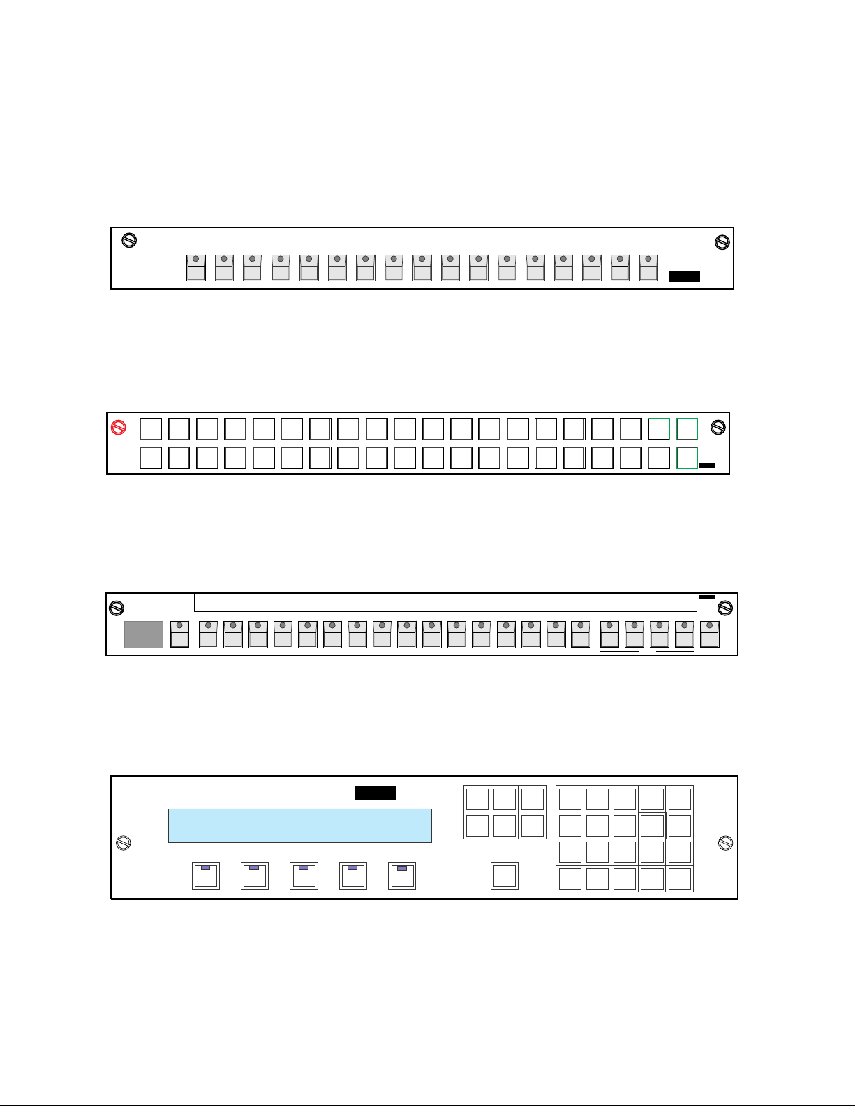
Section 2 — Installation
Control Panel Front Views
Figure 2-7 through Figure 2-10 illustrate the front view of the control
panels.
3529-01
Grass Valley
SRC
1
SRC
17
Grass Valley
Grass Valley
88
SRC
2
SRC
18
SRC
SRC
19
Series6000
Figure 2-7. C16 Button Per–Source Control Panel
SRC
4
3
SRC
20
5
SRC
21
SRC
22
6
7
SRC
23
SRC
24
8
SRC
25
10
9
SRC
26
11
SRC
27
SRC
12
SRC
28
SRC
13
SRC
29
SRC
14
SRC
30
SRC
15
SRC
31
SRC
16
SRC
32
DST
DST
DST
1
2
DST
5
6
SRC
SRC
SRC
SRC
SRC
SRC
SRC
DST
DST
DST
4
3
DST
8
7
Series6000
3529-02
Figure 2-8. C32 Button Per-Source Control Panel
Series6000
3529-03
12345678910111213141516 LEVEL LOCKDESTINATION
2-18
Grass Valley
-
0
RT
V
1
-
2
0
RT
V
DEST
C
A-M01 1VTR-2
---
-
-----
-
VIDEO
AUD-1
Figure 2-9. CMXY Control Panel
CLEAR NEXT
DEST
LOCK PREV
DEST
TAKE
-
AMCV0
T
4
AUD-2
Series6000
-
1R
-
VTR 21
2
---------
T- -CODE
Figure 2-10. CXY Control Panel
NEXT
SRCE
PREV
SRCE
DST
SRC
7
4
1
89
56
32
0
3529-04
Page 64

SMS-6000 Configuration
3
Editor
On-Line Documentation
Overview
This section is available on-line using the
Configuration Editor window. The document uses Acrobat Reader to
display the section and to allow hyperlinks within the document. Acrobat
Reader has an on-line help file available for people unfamiliar with the
tools and commands used by Acrobat.
The Table of Contents is hyperlinked. Additional hyperlinks within the
document are shown by blue underlined text. For best viewing adjust the
magnification to fit your screen for size and readability, recommended
magnification is 100%.
Select these tools to adjust magnification.
Select this tool to access the hyperlinked Table of Contents
Figure 3-1. Acrobat Reader Tool Bar
HELP
button on the SMS-6000
159364-00 SW Ver1.0
The SMS-6000 Configuration Editor allows the creation of configuration
files on a Windows PC platform for the SMS-6000 Signal Management
System. These configuration files can be downloaded to the router and/or
saved to disk.
SMS CFGSW Configuration Software 170234-000
System Software Version 1.0 159398-00
Acrobat Reader Version 2.0 159366-00
Copyright © Tektronix, Inc., Grass Valley Products
3-1
Page 65

Section 3 — SMS-6000 Configuration Editor
Installation
After completing the installation process, Windows will be restarted.
Please close all open applications before beginning the installation.
1. Place the Series 6000 System Software disk (159398-00) in the A: disk
drive.
2. From the Program Manager in Windows chose
RUN
under the
FILE
menu.
3. Type
A:\INSTALL in the Command Line box.
Follow the directions on the screen to install the SMS-6000
Configuration Editor and the on-line documentation. The installation
program will make a directory on the hard disk drive (C:\sms6ce).
NOTES:
If you have Acrobat Reader 2.0 or higher already installed on your
computer it is not necessary to install this version.
HELP
In order to access the on-line documentation using the
buttons in the SMS6000 Configuration Editor, Acrobat Reader needs to be in a directory named
C:\acroread.
4. Put the Acrobat Reader disk (159366-00) in the A:disk drive.
5. From the Program Manager in Windows chose
RUN
under the
FILE
menu.
6. Type
A:\SETUP in the Command Line box.
This will install Acrobat Reader in a directory on the hard disk drive
(C:\acroread).
3-2
Total disk space required is approximately 3.5 megabytes.
NOTE:
After the configuration process is completed the SMS-6000 Configuration
Editor may be removed from the PC’s drive by deleting the C:\sms6ce directory.
Acrobat Reader may be removed by deleting the C:\acroread directory.
Copyright © Tektronix, Inc., Grass Valley Products
159398-00 Software Ver1.0
Page 66

Configuring the SMS-6000 Router
To configure or reconfigure your SMS6000 Router, you will:
Configuring the SMS-6000 Router
1. Create a new configuration, or open and/or copy an existing one
page 3-3).
2. Create (or change, if desired) the configuration items
(see page 3-4) in
this order:
Frames
Virtual Matrices
Levels
Sources and Destinations
Panels
3. Save the configuration
4. Download the configuration to your SMS6000 Router
(see page 3-23) to disk, if desired.
(see page 3-24).
Examples
The configuration for every system is unique to that system; therefore,
your configuration will be unique. To aid in configuring a system, we will
use examples of possible configurations.
Create a New Configuration, or Open and/or Copy an Existing One
(see
■
To create a new configuration, click on
To Open an existing configuration, click on
■
To Copy an existing configuration (without destroying the original),
■
open the configuration, then click on
FILE
FILE
, then
, then
FILE
, then
SAVE AS
NEW
.
OPEN
, and give it a
.
new name.
Figure 3-2. File, Open, and Save As Windows
159398-00 Software Ver1.0
Copyright © Tektronix, Inc., Grass Valley Products
3-3
Page 67

Section 3 — SMS-6000 Configuration Editor
Create (or Change, if Desired) the Configuration Items
The configuration hierarchy is as follows:
Control Panels are configured to Take Sources to Destinations , which
have inputs and outputs on one or more
of one or more
crosspoints in a
Virtual Matrices , each of which contains some or all of the
Frame .
Therefore, the configuration should be done in the proper sequence
beginning with the
Frames , then Virtual Matrices , Levels , Sources and
Destinations , and finally the Control Panels .
Pre-Configuration Information
In order to make configuration proceed as smoothly as possible, make a
written list of the names and addresses of the components of your system:
Frames, Virtual Matrices, Levels, Sources, Destinations, and Control
Panels. This list will help you design your system to make the best use of
your existing equipment.
Levels , each of which is made up
Names
Frames, Sources, Destinations, Control Panels and other components of the
SMS-6000 Configuration Editor all have Names. Names are essential to the
configuration and operation of the SMS-6000.
Please observe the following SMS-6000 Naming Convention
■
Names must be six or fewer characters in length.
■
Names are case sensitive. For example, the system will interpret CAM1
as a different name from Cam1.
Spaces in names are discouraged. If you want to use a space in a name,
■
use an underscore or a hyphen.
Levels
There are 3 types of Level:
Simple —This Level encompasses an entire Frame and a Take on this
level will only change a single crosspoint (or the Left and Right
crosspoints on a Stereo Audio Frame).
The vast majority of Levels will be Simple.
Partial Frame —This Level is one of two or more in the same Frame.
3-4
Custom Multi-Xpt —A Take on this Level can change two or more
crosspoints; the Level may span multiple Frames.
Levels can be both Partial Frame and Custom Multi-Xpt; for example; a
1
2
⁄
Component Analog Video level could take up 1
frames for its R, G & B
virtual matrices.
Copyright © Tektronix, Inc., Grass Valley Products
159398-00 Software Ver1.0
Page 68

Configuring the SMS-6000 Router
Virtual Matrices
The Virtual Matrix is a software construct created to allow you to:
■
Split a single Frame into more than one Level; each block of crosspoints
will form one Virtual Matrix.
Set up any Frame in such a way that a Take on a given Level will
■
change more than one crosspoint (for example, the R, G and B
crosspoints on a Component Analog Video Level; the R, G and B blocks
of crosspoints will form 3 Virtual Matrices).
The configuration of most Frames, will only require one Virtual Matrix.
Simple Frames, Virtual Matrices, Levels, Sources, and Destinations
1. Select
2. Configure your Simple
a. Select
b. Select
NEW
to create a configuration file.
(see page 3-4) Frames:
FRAME
to access the Frame Actions window.
NEW
to access the New Frame window.
c. Select the appropriate Frame Type.
d. Default Frame Name and Address will appear (you can change the
Address and Frame Name if desired).
e. Select
NOTES:
OK
to return to Frame Actions window.
Stereo Analog Audio Frames should be configured as Simple Frames.
Serial Video Frames can contain GVG PCB Input Simms, Quartz PCB Input
Simms, or both types of Simms on a single frame (newer frames contain only GVG
PCB Input Simms). If your frame has mixed Simms; click on
SET MIXED TYPES
;
then check all Inputs that contain Quartz Simms.
Data matrix frames allow the frame's “disconnect” behavior to be configured.
Normally, if you select a source that lacks the Data Matrix level, and Take it to a
destination that has the Data Matrix level, the Take will not affect the status on the
Data Matrix level of the destination. If the
DISCONNECT IF SOURCE LACKS INPUT
checkbox is checked, this same Take will cause a disconnect on the Data Matrix
level of the destination (even though the disconnect occurred, the “taken” source
will still appear as status on this level of the destination).
159398-00 Software Ver1.0
3. When configuring more than one Frame of the same type:
a. Highlight an existing Frame entry in the Frame Actions window.
b. Select
COPY
. The Frame Name, Address, and Type will appear with
defaults.
c. Select
EDIT
to change the default information for a copied Frame, if
desired.
Copyright © Tektronix, Inc., Grass Valley Products
3-5
Page 69

Section 3 — SMS-6000 Configuration Editor
4. Repeat steps 2 and 3 until all Simple Frames have been entered.
CLOSE
5. Select
to return to SMS-6000 Configuration Editor window.
Data Matrix
Frame and
Checkbox
3-6
Figure 3-3. Creating a New Serial Video or Data Matrix Frame
6. Select
7. Select
VMTX
to access the Virtual Matrix Actions window.
DEFAULT NEW
to create Virtual Matrices (see page 3-5) for the
configured Frames.
NOTES:
A Serial Video Frame will need to have its Virtual Matrix edited for
signal type.
A Stereo Analog Audio Frame is configured as a single Virtual Matrix.
8. Select
CLOSE
to return to the SMS-6000 Configuration Editor window.
Copyright © Tektronix, Inc., Grass Valley Products
159398-00 Software Ver1.0
Page 70

Configuring the SMS-6000 Router
Figure 3-4. Virtual Matrix Actions Window
9. Select
10. Select
LEVEL
to access the Level Actions window.
DEFAULT NEW
to create Levels (see page 3-4) for the newly
configured Virtual Matrices.
CLOSE
11. Select
to return to the SMS-6000 Configuration Editor window.
159398-00 Software Ver1.0
Figure 3-5. Level Actions Window
Copyright © Tektronix, Inc., Grass Valley Products
3-7
Page 71

Section 3 — SMS-6000 Configuration Editor
If you want Sources and Destinations to contain all of your Simple Levels
(see page 3-4) but no Partial Frame or Custom Multi-Xpt ones (if any):
12. Select
13. Select
14. Select
15. Select
16. Select
17. Select
SOURCE
DEFAULT NEW
CLOSE
DEST
DEFAULT NEW
CLOSE
to access the Source Actions window.
to create Sources.
to return to the SMS-6000 Configuration Editor window.
to access the Destination Actions window.
to create Destinations.
to return to the SMS-6000 Configuration Editor window.
3-8
Figure 3-6. Source and Destination Actions Windows
Copyright © Tektronix, Inc., Grass Valley Products
159398-00 Software Ver1.0
Page 72

Configuring the SMS-6000 Router
Partial Frame and Custom Multi-Xpt: Frames, Virtual Matrices, and Levels
1. Configure your Partial Frame (see page 3-4) and Custom Multi-Xpt (see
FRAME
page 3-4) Frames by selecting
NEW
window, then
to access the New Frame window.
2. Select the appropriate Frame Type.
Default Frame Name and Address will appear (you can change the
Address and Frame Name if desired).
to access the Frame Actions
NOTES:
Stereo Analog Audio Frames should be configured as Simple Frames.
Serial Video Frames can contain GVG PCB Input Simms, Quartz PCB Input
Simms, or both types of Simms on a single frame (newer frames contain only GVG
PCB Input Simms). If your frame has mixed Simms; click on
SET MIXED TYPES
;
then check all Inputs that contain Quartz Simms.
Data matrix frames allow the frame's “disconnect” behavior to be configured.
Normally, if you select a source that lacks the Data Matrix level, and Take it to a
destination that has the Data Matrix level, the Take will not affect the status on the
Data Matrix level of the destination. If the
DISCONNECT IF SOURCE LACKS INPUT
checkbox is checked, this same Take will cause a disconnect on the Data Matrix
level of the destination (even though the disconnect occurred, the “taken” source
will still appear as status on this level of the destination).
3. Select
OK
to return to Frame Actions window.
When configuring more than one Frame of the same type:
a. Highlight Frame entry in the Frame Actions window.
COPY
b. Select
. The Frame Name, Address, and Type will appear with
defaults.
EDIT
c. Select
to change the default information for a copied Frame, if
desired.
159398-00 Software Ver1.0
4. Repeat steps 2, 3, and 4 until all Partial Frame and Custom Multi-Xpt
Frames have been entered.
CLOSE
5. Select
Copyright © Tektronix, Inc., Grass Valley Products
to return to SMS-6000 Configuration Editor window.
3-9
Page 73
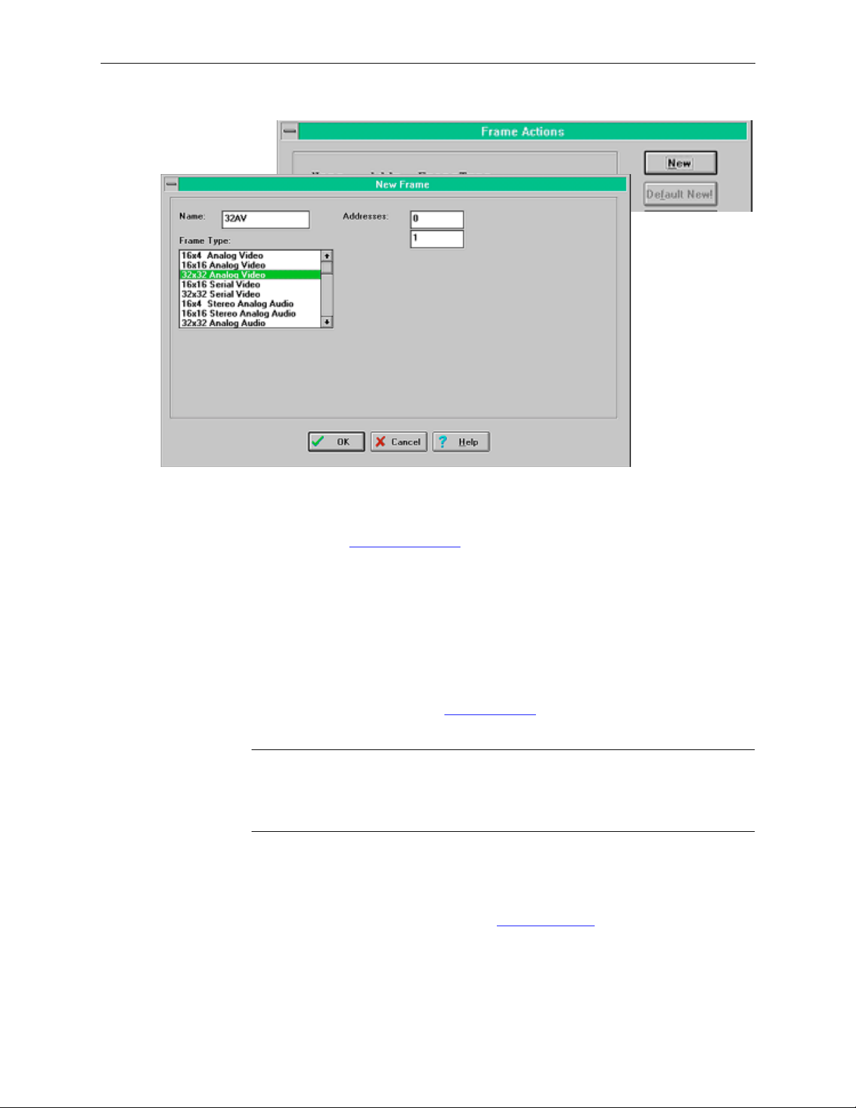
Section 3 — SMS-6000 Configuration Editor
Figure 3-7. Partial Frames and Custom Multi-Xpts Frames Windows
6. Select
7. Configure Virtual Matrices
VMTX
to access the Virtual Matrix Actions window.
[see page 3-5 (blocks of crosspoints within
a Frame)] for all Frames that are either Partial Frame (contain more
than one Level) or Custom Multi-Xpt [contain more than one block of
crosspoints expected to switch on the same Level (e.g., R and G might
be in a single Frame)].
NEW
a. Select
b. Select
to access New Virtual Matrix window.
FRAME
.
c. Enter Name.
d. If selected frame is a Partial Frame
FRAME?
NOTES:
You will need to assign Inputs and Outputs in the fields.
A Serial Video Frame will need to have its Virtual Matrix edited for
(see page 3-4) click on
signal type.
A Stereo Analog Audio Frame is configured as a single Virtual Matrix.
e. If selected Frame is a Serial Digital Frame you will need to select
Signal Type.
f. Select
OK
to return to Virtual Matrix Actions window.
SPLIT
8. Select
DEFAULT NEW
to create one Virtual Matrix (see page 3-5) for each
Frame that still does not have a Virtual Matrix.
CLOSE
9. Select
3-10 Copyright © Tektronix, Inc., Grass Valley Products 159398-00 Software Ver1.0
to return to the SMS-6000 Configuration Editor window.
Page 74
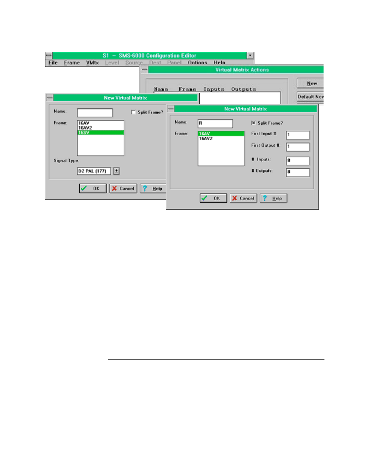
Configuring the SMS-6000 Router
Figure 3-8. Partial Frame and Multi-Xpt Frames Virtual Matrices Windows
10. Select
LEVEL
to access the Level Actions window to configure any
complex levels.
NEW
11. Select
to Access the New Level window.
12. Select one or more Virtual Matrices that will belong to this level.
13. Enter Level Name.
OK
14. Select
to return to Level Actions window.
15. Repeat until all Levels are configured.
CLOSE
16. Select
NOTE:
You can select a block of contiguous items by holding down the mouse
to return to SMS-6000 Configuration Editor window.
button and dragging or select non-contiguous items by clicking on them.
159398-00 Software Ver1.0 Copyright © Tektronix, Inc., Grass Valley Products 3-11
Page 75

Section 3 — SMS-6000 Configuration Editor
Figure 3-9. Partial Frame and Custom Multi-Xpt Levels Windows
Sources and Destinations
The configuration process is the same for both Sources and Destinations. The only
variation is that Inputs are assigned to Sources and Outputs are assigned to
Destinations.
1. Select
SOURCE
window.
For each group of Sources or Destinations:
2. Select
NEW
3. Create one Source or Destination, named xxx1, where xxx is the name of the
group.
Remember the 6 character limit
Sources or Destinations in the group, the group name should be 4 characters or
less.
4. Select the Level/s you want for this Source or Destination.
5. To assign Inputs or Outputs:
a. Select
b. Enter the physical connector number(s).
or
DEST
to access the Source Actions or Destination Actions
.
SET/VIEW INPUTS
or
(see page 3-4)—if you will have 10 or more
SET/VIEW OUTPUTS.
3-12 Copyright © Tektronix, Inc., Grass Valley Products 159398-00 Software Ver1.0
Page 76

Configuring the SMS-6000 Router
NOTE:
The first free Input or Output is assigned as a default if you choose to skip
this step.
You can create up to 80 Sources and 80 Destinations.
Data Matrix Frames require that the 80th source be unconfigured. This 80th
Source will become the IDLE Source. This does not affect the configuration of the
other 79 Sources.
6. Click on
7. Click on
OK
to return to the New/Edit window.
OK
to create this Source or Destination and return to the
Actions window.
COPY
8. Click on
to increment the inputs/outputs for creating the next
source/destination of this group.
9. Repeat steps 3 to 9 until the group is complete.
10. Repeat steps 2 to 9 for the next group.
If you used Default New to create your Sources/Destinations and only want to change
the name of a group:
11. Highlight all the default entries of the group except for the first entry.
12. Select
DELETE
to remove the entries.
13. Highlight the remaining Source/Destination of the group in the
Actions window.
14. Select
EDIT
.
15. Change the Name.
16. Click on
17. Click on
OK
to return to Actions window.
COPY
to increment the inputs/outputs for creating the next
source/destination of this group.
CLOSE
18. Click on
to return to SMS-6000 Configuration Editor window,
when finished configuring all Sources/Destinations.
IMPORTANT!
It is very important that the configuration of all
Levels, Sources
Control Panels
, and
Destinations
are configured
(including all names) is completed before
Frames, Virtual Matrices
,
159398-00 Software Ver1.0 Copyright © Tektronix, Inc., Grass Valley Products 3-13
Page 77
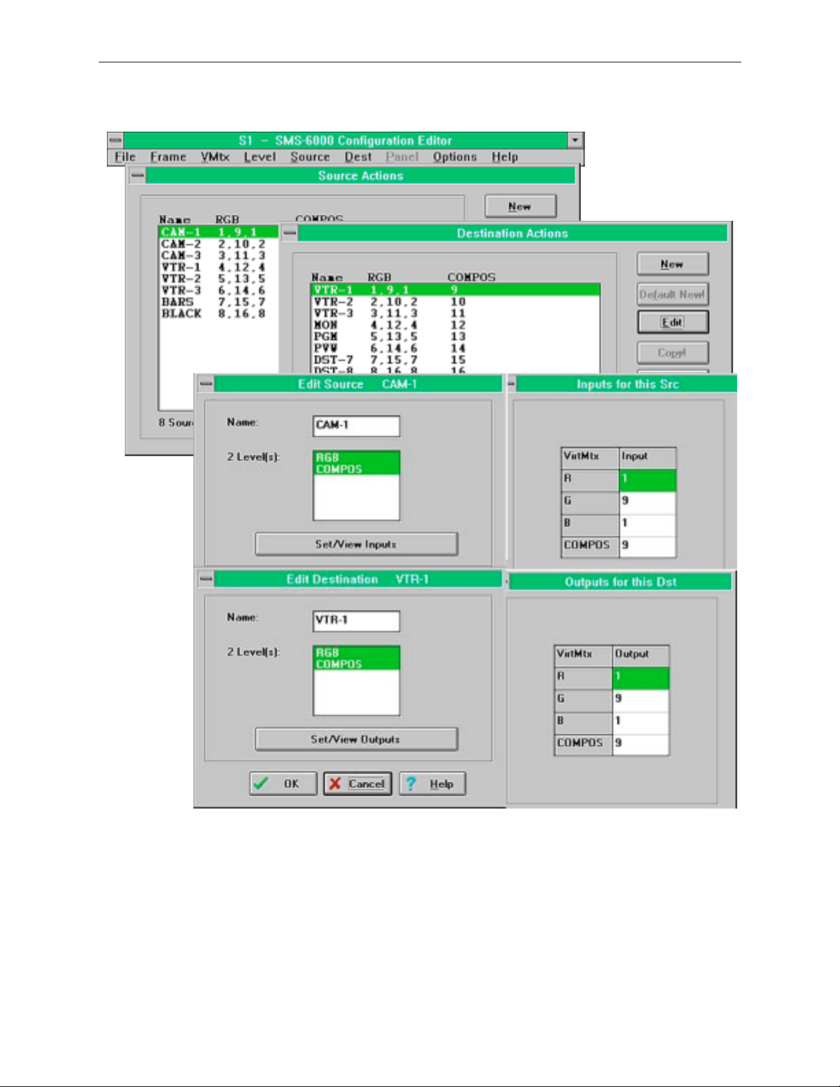
Section 3 — SMS-6000 Configuration Editor
.
Figure 3-10. Partial Frame and Custom Multi-Xpt Sources and Destinations Windows
3-14 Copyright © Tektronix, Inc., Grass Valley Products 159398-00 Software Ver1.0
Page 78
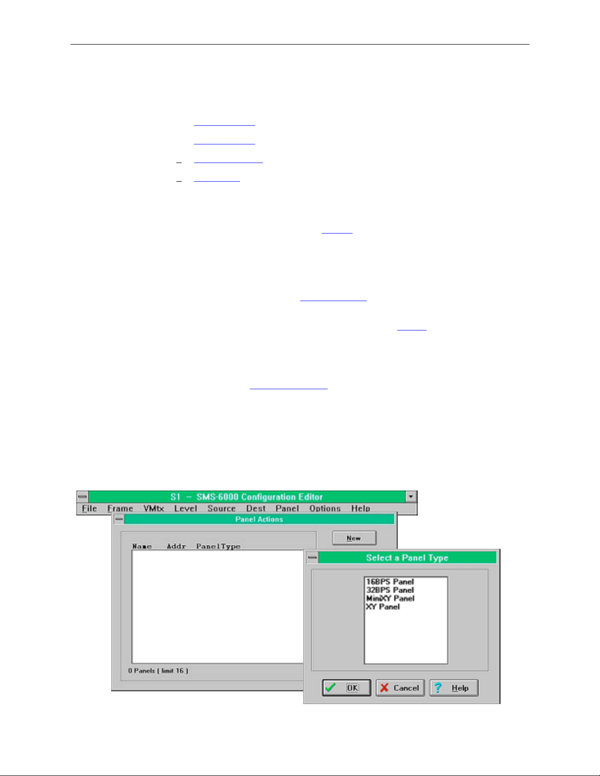
Configuring the SMS-6000 Router
Panel Configuration
The SMS-6000 offers a choice of control panels:
■ 16BPS Panel (see page 3-16)—16 button-per-source
■ 32BPS Panel (see page 3-17)—32 button-per-source
■ MiniXY Panel (see page 3-19)
■ XY Panel (see page 3-20)
The maximum number of panels on the SMS-6000 is 16.
All Panel Types
Source, Destination and Level names (see page 3-4) on the buttons are
abbreviated to 3 characters in the SMS-6000 Configuration Editor; to view
the full name, click on the button.
The color of a button indicates its type (i.e., Source Button, Destination
Button, or Level Button.) The default color: button type relationship can be
changed in the Options-> Button Colors
from the SMS-6000 Configuration Editor window.
You can only change the type of a button in the 32BPS
If you have more than one panel of the same type, that you want to
configure similarly, create and configure the first one, then click on
automatically create and configure the second.
Remember the 6 character limit
(see page 3-4)—if you will have 10 or more
panels of the same type the first name should be 5 characters or less.
(see page 3-27) window accessed
panel (see page 3-17).
COPY
to
1. Select
2. Select
PANEL
to access the Panel Actions window.
NEW
.
3. Select Panel Type.
4. Click on
OK
.
Figure 3-11. Panel Windows
159398-00 Software Ver1.0 Copyright © Tektronix, Inc., Grass Valley Products 3-15
Page 79
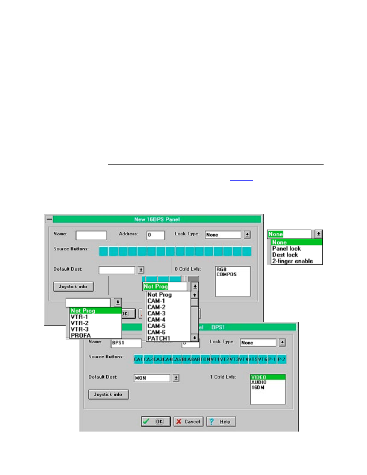
Section 3 — SMS-6000 Configuration Editor
16BPS Panel
The BPS 16 Panel is configured to take any 16 sources to a single destination
on a given level or set of levels.
1. Enter Panel name if desired.
2. Default address appears, change if desired.
3. Select a Source button to access drop-down combobox of available
Sources and assign sources.
4. Use drop-down combobox to assign Default Destination.
5. Select Level.
6. Use drop-down combobox to assign Lock Type
NOTE:
Joystick Information can be entered at this point. The Joystick window is
the same for several panels. Please refer to the Joystick
this document.
OK
or
Select
CANCEL
to continue.
(see page 3-23).
(see page 3-22) section of
Figure 3-12. 16BPSPanel
3-16 Copyright © Tektronix, Inc., Grass Valley Products 159398-00 Software Ver1.0
Page 80

Configuring the SMS-6000 Router
32BPS Panel
32BPS is so named because it can be set up to control 32 Sources & 8
Destinations, but it need not be--could have 20 Sources & 20 Destinations,
or 32 Sources 6 Destinations & 2 Levels, or whatever adds up to 40 buttons.
This panel uses buttons that can be re-labelled to reflect changes in your
system and LED status indicators for easy reading.
When you create a new 32BPS panel, the “Set button types” window
appears, allowing you to change the default button types if desired. To
bring up this window later, go to the lower right section of the 32BPS
dialog box and click on the button type you want to change.
1. Select either Source, Destination, Level, or Lock in the Set Type to:
subpanel. The selected button type will appear in “Click on button to
change its type to:”
2. Select any button in the panel and it will change to your selected button
type.
3. Select
CANCEL
to return to New/Edit 32BPS window.
OK
or
4. Enter Panel name if desired.
5. Default address appears, change if desired.
6. Select a Source button to access drop-down combobox of available
Sources and assign sources.
7. Select a Destination button to access drop-down combobox of available
Destinations and assign destinations.
8. Use drop-down combobox to assign Default Destination.
9. Select Levels.
10. If Lock was assigned to a button, use drop-down combobox to assign
Lock Type
NOTE:
Joystick Information can be entered at this point. The Joystick window is
the same for several panels. Please refer to the Joystick
(see page 3-23).
(see page 3-22) section of
this document.
OK
or
Select
159398-00 Software Ver1.0 Copyright © Tektronix, Inc., Grass Valley Products 3-17
CANCEL
to continue.
Page 81

Section 3 — SMS-6000 Configuration Editor
Figure 3-13. 32BPS Panel Windows
3-18 Copyright © Tektronix, Inc., Grass Valley Products 159398-00 Software Ver1.0
Page 82
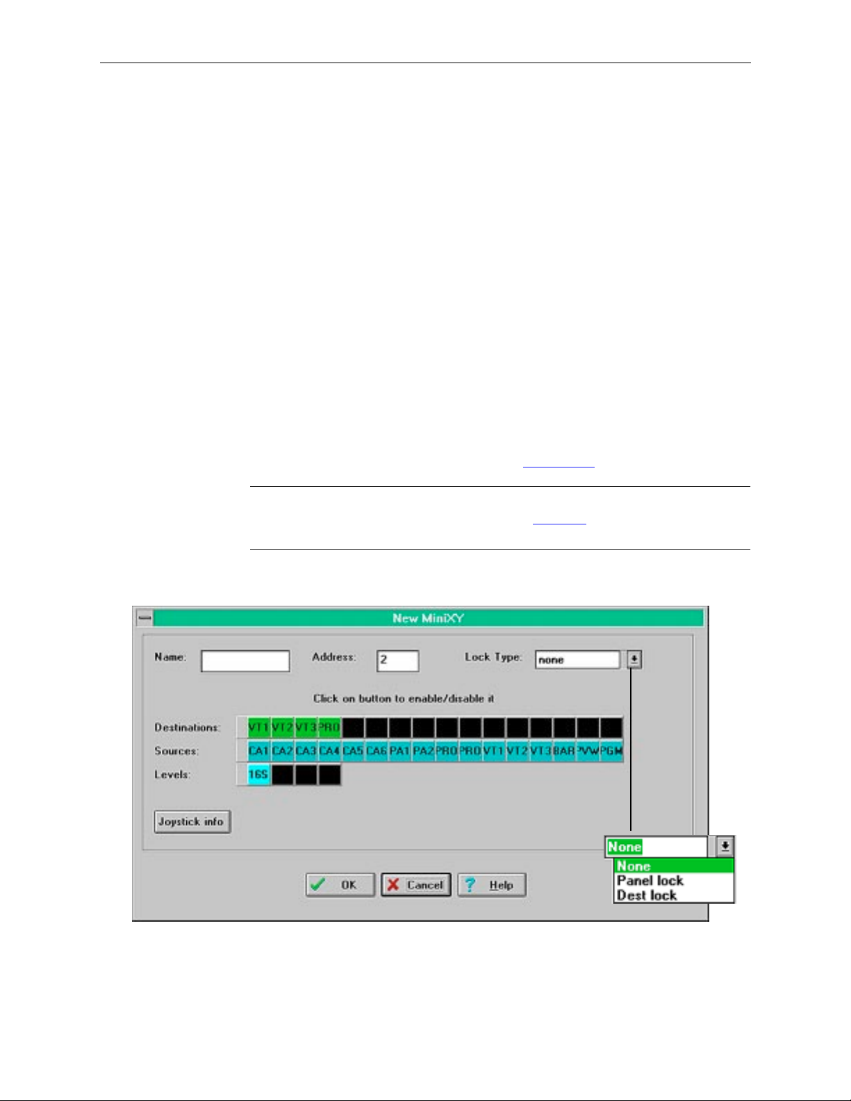
Configuring the SMS-6000 Router
MiniXY Panel
The Mini XY Panel has 16 SELECT buttons to choose from the 16 sources
(inputs) and 16 destinations (outputs). They are shared between source
and destination selection. Here the appearance of the panel has been
modified for the SMS-6000 Configuration Editor to show two separate sets
of 16 buttons each, for sources and destinations.
The MiniXY Panel has limited functionality; it can only control the first 16
sources, the first 16 destinations, and the first 4 levels. To toggle control of
any of these items, click on the button representing it.
1. Enter Panel name if desired.
2. Default address appears, change if desired.
3. Click on Destinations or Sources to enable/disable for a total of 16
Destinations and Sources.
Destinations, Sources, and Levels are set by the configuration done in
the Level, Source, and Dest menus.
4. Use drop-down combobox to assign Lock Type
NOTE:
Joystick Information can be entered at this point. The Joystick window is
the same for several panels. Please refer to the Joystick
this document.
5. Select
OK
or
CANCEL
to Continue.
(see page 3-23).
(see page 3-22) section of
Figure 3-14. Mini XY Panel Window
159398-00 Software Ver1.0 Copyright © Tektronix, Inc., Grass Valley Products 3-19
Page 83

Section 3 — SMS-6000 Configuration Editor
XY Panel
The keypads of the XY Keypad Panel can be configured in the arrangement
most convenient for you. The two Suffix arrangements are Calculator or
Telephone (with or without the characters A-F). Calculator is the more
common choice.
1. Enter Panel name if desired.
2. Default address appears, change if desired.
3. Use drop-down comboboxs for Default Destination and Lock Type
(see
page 3-23). Levels are set by the configuration done in the Level menu.
4. Select a keypad button to assign a prefix to a key. In the text window
enter the desired prefix.
5. Select
6. Select
NOTE:
REMOVE CHOP KEY
MOVE/SET CHOP KEY
Joystick Information can be entered at this point. The Joystick window is
the same for several panels. Please refer to the Joystick
to remove the Chop from the panel.
to move or add the Chop.
(see page 3-22) section of
this document.
7. Select
OK
or
CANCEL
to Continue.
3-20 Copyright © Tektronix, Inc., Grass Valley Products 159398-00 Software Ver1.0
Page 84

Configuring the SMS-6000 Router
Figure 3-15. XY Keypad Panel Windows
159398-00 Software Ver1.0 Copyright © Tektronix, Inc., Grass Valley Products 3-21
Page 85

Section 3 — SMS-6000 Configuration Editor
Joystick
The Joystick Override is used for remote source selection, for example, in
order to match the color balance of several cameras. When the Joystick is
pressed, the associated source is switched to the destination specified in the
Joystick Override window. When the Joystick is released, the panel will
revert to the previous selection made by the control panel.
1. Select
MiniXY
JOYSTICK INFO
(see page 3-19), or XY Panel (see page 3-20) to access the Joy
on the 16BPS (see page 3-16), 32BPS (see page 3-17),
Stick Override window.
2. Select a Source button to access drop-down combobox of available
Sources and assign sources to Pins.
3. Use drop-down combobox to assign Destination.
4. Select Level.
5. Select
CANCEL
to Continue.
OK
or
Figure 3-16. Joy Stick Override Window
3-22 Copyright © Tektronix, Inc., Grass Valley Products 159398-00 Software Ver1.0
Page 86

Configuring the SMS-6000 Router
Lock Types
MiniXY and XY Panels have: None, PanelLock, and DestLock
16BPS and 32BPS Panels have: None, PanelLock, DestLock, and 2-Finger
Enable
■ DestLock—This lock is active only for a particular Destination. To
select it:
a. The
b. The
Now, attempting to select any button on the originating panel (other
than the
and have no effect. The operator has the choice of making any or all
Destinations locked on the originating panel. All other panels on the Qlink are unaffected.
■ PanelLock—This locks the panel originating the lock for all
destinations. Attempting to select any button on the panel (except
LOCK
unaffected.
■ 2-Finger Enable—To do a Take, hold down the
finger & press the
Save the Configuration
1. Select
2. Select
3. Enter File name (if needed for a new file).
DESTINATION
LOCK
button is pushed.
LOCK
to be locked is made active
button or
DESTINATION
select button) will result in a beep
) results in a beep and no effect. All other panels on the Q-link are
LOCK
button with 1
SOURCE
FILE
.
SAVE
(for a edited file) or
button with another.
SAVE AS
(for a new file).
4. Verify that Directory/Drive is the one where you want to save the file.
5. Verify that Save File as Type says Config files.
6. Click on
159398-00 Software Ver1.0 Copyright © Tektronix, Inc., Grass Valley Products 3-23
OK
.
Figure 3-17. Save Configuration Windows
Page 87

Section 3 — SMS-6000 Configuration Editor
Download the Configuration to Your SMS-6000 Router
1. Verify that there is a RS232 serial connection between one of the PC's
serial (COM) ports and the Master Frame's serial port.
NOTES:
Section 2 Installation, sub-section Configuring the Frame in the Series
6000 Compact Signal Management System manual, covers the Installation and
set-up of the frames.
Serial I/F links must be set for RS232.
2. From the SMS-6000 Configuration Editor, verify the Comm Parameters
(see page 3-27).
a. Select
b. Select
OPTIONS
COMM PARAMETERS
.
.
c. Settings should be:
Com Port: is the Com Port actually connected
Com Speed: 9600 baud
Parity: none
Data Bits: 8+1
3. The configured addresses for Frames and Panels match their actual
rotary hex switch setting.
If you change this setting, press the Reset button on the Frame or Panel.
NOTE:
Compare the Frame and Panel rotary hex addresses to their configured
addresses by checking the Frame Actions and Panel Actions windows
4. One and only one control board, on one and only one frame, is set to be
the Master.
The dip switch settings on the Master are Switch 1-up, Switch 2-down,
Switch 3-down, and Switch 4-up. On Slave boards all dip switches are
set in the up position.
Reset frame after changing dip switch settings.
3-24 Copyright © Tektronix, Inc., Grass Valley Products 159398-00 Software Ver1.0
Page 88

Configuring the SMS-6000 Router
Reset Switch
9
8
A
7
B
|
|
|
|
6
|
|
5
4
3
C
|
|
|
|
D
|
|
E
|
|
|
|
2
F
1
0
ON EPG
312 4
Figure 3-18. Rotary, Dip, and Reset Switches
5. Open a configuration if there is no configuration currently open.
a. From the SMS-6000 Configuration Editor, select
b. Select
OPEN
.
c. Select desired configuration file from directory.
d. Click on
OK
.
LED Indicator
Dip Switches
3rd from left is down for Master, Up for Slave
Rotary Hex Switch to set address.
FILE
.
6. Download the configuration.
a. From the SMS-6000 Configuration Editor, select
b. Select
DOWNLOAD
.
FILE
.
c. A window showing download status appears. The download takes
roughly a minute or two, depending on file size.
After the download is complete, the SMS6000 Router will come up with the
new configuration.
If you can't connect to the router, double-check the conditions in step 1, or
try connecting to a different serial port on the master frame.
Figure 3-19. Download Status and Error Windows
159398-00 Software Ver1.0 Copyright © Tektronix, Inc., Grass Valley Products 3-25
Page 89

Section 3 — SMS-6000 Configuration Editor
Miscellaneous
Welcome
Figure 3-20. Welcome Window
The Welcome window will appear when the
SMS-6000 Configuration Editor is loaded.
File Menu
. The File menu has the following unique features:
■
DOWNLOAD TO FILE
■
ERROR CHECK CONFIG
this selection is for future use.
does a thorough error check of the entire
configuration. It is recommended that you use this feature if
you have any doubts about the consistency of the configuration.
■
SAVE BUTTON LABELS TO FILE
is used to create a text file of the
Button Labels. This text file can be used in an application such
as Excel to create custom button labels.
■
Figure 3-21. File Menu
Actions Windows Buttons
All Actions windows have the following buttons:
■
NEW
to add a new item.
■
DEFAULT NEW
■
EDIT
to modify an existing item.
■
COPY
to copy an existing item.
to add default entries.
■
UNDO
to undo the last entry.
■
CLOSE
to close the Action window.
■
HELP
to access the on-line documentation.
NOTE:
Whenever a button appears gray on the screen that function is not
available.
Figure 3-22. Action Windows Buttons
3-26 Copyright © Tektronix, Inc., Grass Valley Products 159398-00 Software Ver1.0
Page 90
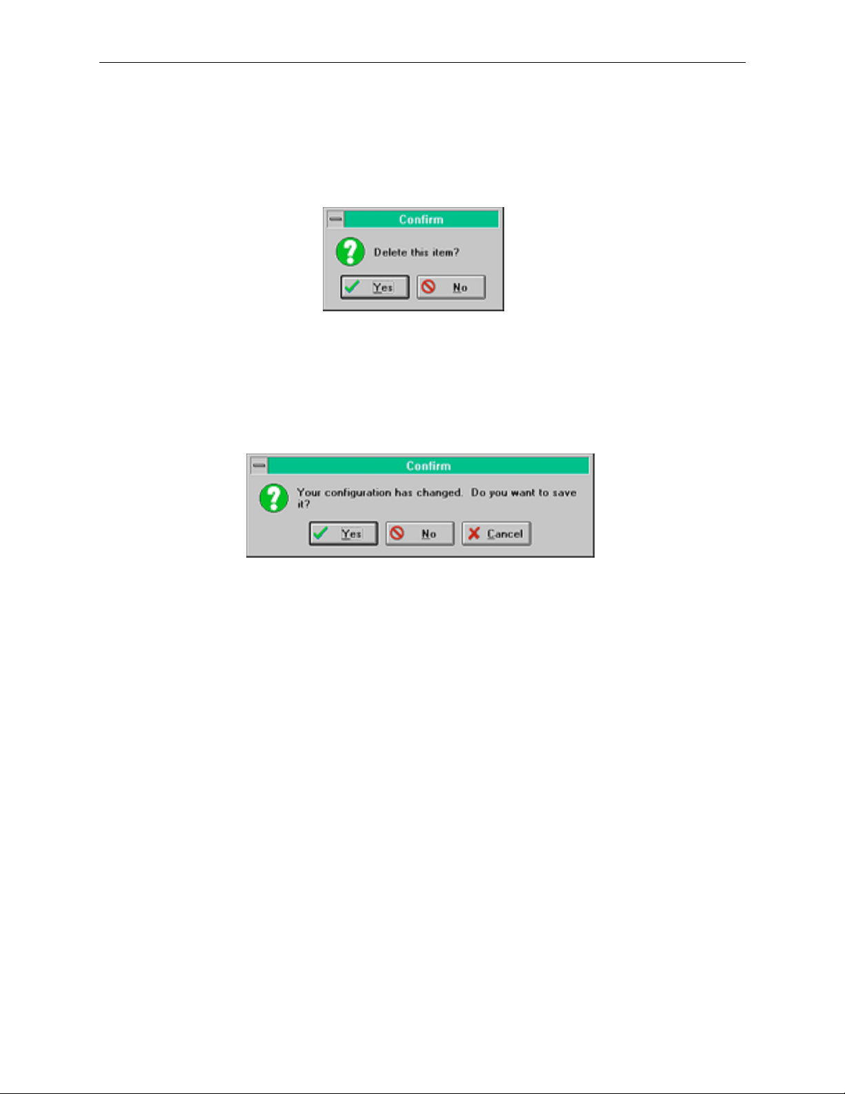
Delete Confirmation Window
Miscellaneous
Exit
When you choose
automatically appear. You will be asked to confirm your decision to delete
the current item.
Figure 3-23. Delete Confirmation Window
EXIT
will close the SMS-6000 Configuration Editor. If you try to exit the
SMS-6000 Configuration Editor after creating a new file or making changes
to an existing file the following confirmation window will appear:
DELETE
, the Delete Confirmation window will
Options Menu
Figure 3-24. Exit Confirmation Window
Comm Parameters
The Comm Parameters window shows the system default. You may
change these parameters.
Button Colors
You may change the colors of the Source, Destination, Level, Lock, Chop,
or Prefix Buttons using buttons colors window.
1. Select which button you want to change color.
2. Select the new color from the Basic Colors or Custom Colors in the
Color window.
3. Select button and click to assign colors as desired.
4. Select
OK
or
CANCEL
to continue.
159398-00 Software Ver1.0 Copyright © Tektronix, Inc., Grass Valley Products 3-27
Page 91

Section 3 — SMS-6000 Configuration Editor
Figure 3-25. Comm Parameters and Button Colors Windows
Help Location
The Help Information window displays the file names and path used to
access the on-line documentation.
Figure 3-26. Help Information Window
3-28 Copyright © Tektronix, Inc., Grass Valley Products 159398-00 Software Ver1.0
Page 92

Help Menu
Miscellaneous
About
The About window displays the current version of software for the SMS6000 Configuration Editor you are using.
Figure 3-27. About Window
Help
The
HELP
button loads Acrobat Reader. In the Open Window select
SMS6CEH.PDF. After loading the on-line documentation you may
minimize the help window and return to the SMS-6000 Configuration
Editor.
Figure 3-28. Open Window for On-Line Documentation
159398-00 Software Ver1.0 Copyright © Tektronix, Inc., Grass Valley Products 3-29
Page 93

4
Introduction
Control Panels
Once the system has been fully installed you can start to use it. This section
describes the Series 6000 control panels and their operation.
4-1
Page 94
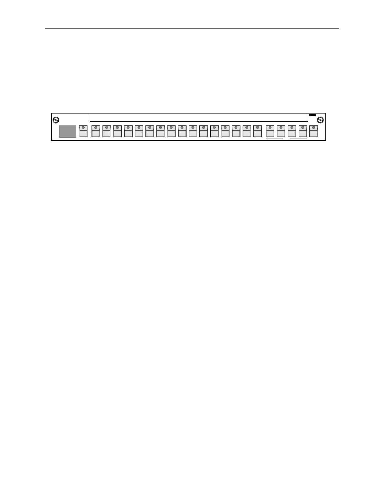
Section 4 — Control Panels
SMS–CMXY Control Panel
The SMS–CMXY (Mini-XY) panel can be supplied as a remote control
panel or as a local control panel (SMS CMXY-LP) which fits the front of a
1RU matrix frame. The SMS–CMXY Control Panel is illustrated in Figure
4-1.
Grass Valley
88
Description
12345678910111213141516 LEVEL LOCKDESTINATION
Figure 4-1. SMS–CMXY Control Panel
Series6000
3529-03
Operation
This panel has 16 SELECT buttons to choose the 16 sources (inputs) and 16
destinations (outputs). They are shared between source and destination
selection using a further switch to engage the destination select mode. A
dual seven segment LED display is used to show the destination which is
currently being controlled.
Designation Strip
A slide-in designation strip may be used to label both sources and
destinations by easy-to-remember names above the SELECT buttons. It can
also be used to show the names of the breakaway levels in use.
Computer Port
The computer port is not available with the current version of firmware.
All of the buttons can be configured to operate in different ways, so the
description that follows is for the factory default configuration. However,
users may alter the configuration to their specific requirements.
4-2
Page 95

SMS–CMXY Control Panel
Destinations
Press the DESTINATION button to engage the destination select mode. The
LED in this button lights and the LEDs in the SELECT buttons light to show
which destinations can be selected; so if destinations 5, 6, 7 and 8 are
allowed to be selected from the panel then all these four LEDs will light up.
This menu acts as a warning to show that the panel is in an unusual mode,
otherwise the operator might be confused as to whether the panel is in
source or destination mode.
Press one of the lit SELECT buttons to choose a new destination. The
number corresponding to the button pressed is transferred to the numeric
display to show the current destination, and the source currently selected
to that destination is shown by one of the LEDs in the select buttons.
Sources
When the destination has been selected, pressing a source button initiates
the take or cut of that source.
Breakaways
Four buttons are provided to enable breakaway selections of signal levels
such as video, audio 1, audio 2, and time code. These buttons can be labeled
to suit each application using the designation strip. The system
configuration determines which buttons are active, i.e., which breakaways
are allowed. For example, in a video only system the left hand LED only
would be lit, and in a video and single level (mono) audio system a
breakaway may be required, in which case the left two buttons would be
used.
If the breakaways are allowed, then when a new destination is selected, all
the level buttons light up denoting the married mode in which all switching
levels are switched simultaneously. This is the normal condition. If a
breakaway selection is required then press the buttons to deselect the levels
which are not required to switch. Then press a SELECT button to choose a
new source on the breakaway level.
If a breakaway is selected then source LEDs flash to denote that a
breakaway condition exists. If all four levels are selected to different source
signals then three of the LEDs flash while the fourth is steady. To find out
which source LED corresponds to a particular signal level, select the
desired level (by deselecting the other levels) and the steady LED is the
source selected on that level of the matrix.
Note that if more than one level is lit then the steady LED corresponds to
the left-most lit level button.
4-3
Page 96

Section 4 — Control Panels
Lock
This button allows you to protect a source/destination selection. The
LOCK button locks the panel or other panels from making further
selections. The lock mode can function in several ways; it is possible to lock
your own panel, or all other panels or even all panels; further, when you
press the LOCK button it can lock just the current destination or it can lock
all destinations. The choice of lock modes is set in the software
configuration.
1. Press the button once to lock the selection/panel. The LED lights to
show that the panel is locked.
2. Press the button again to unlock the selection/panel.
3. The panel remembers the lock status so that when a destination is
locked and this destination is reselected then the lock button will light
to show that this destination is locked.
Trace
Sometimes you may want to take a signal source out of service, but you are
not sure if it is being used anywhere. The Trace feature allows you to check
quickly to which destinations a particular source is being sent.
1. Select the lock mode.
2. Press and hold the SELECT button for the source you wish to trace.
Note that the LED does not light up.
3. After about half a second the SELECT buttons will light to show you all
the destinations to which the source is currently being routed.
4. Release the button when you have finished and the panel will revert to
its normal mode, although you must exit the lock mode before you can
make new crosspoint selections.
Chop
This feature is useful for engineering checks and system alignment of gains
and phasing. In this mode the output switches rapidly between two inputs.
Note that you can select chop mode only when a single breakaway is
selected. The output remains in chop mode until any button on the panel
is pressed, or until a source is changed on the current destination by
another control panel or by an external computer.
4-4
Page 97

SMS–CMXY Control Panel
Joystick or Microswitch Override
This feature is used for matching the color balance of several cameras.
Microswitches in the joysticks of camera control units are pressed by the
engineer conducting the line-up to select the camera in use onto the line-up
monitor. It overrides the current selection made on a remote panel. When
the microswitch contact is released the override selection reverts to the
previous selection made on the conventional panel.
Each control panel can support up to eight cameras. The user indicates in
the software configuration which inputs of the matrix are selected by the
joystick contacts. Normally video only is selected by the joystick, but there
is no limitation placed by the system and any level may be selected.
1. Press and hold the joystick to make an override selection.
2. Release the joystick to return to the previous selection made by the
panel.
3. If two or more joystick buttons are pressed, they queue or stack with
the last press taking priority.
4-5
Page 98

Section 4 — Control Panels
SMS–C16BPS Control Panel
The SMS–C16 Button-Per -Source Control Panel is illustrated in Figure 4-2.
3529-01
Grass Valley
Description
Operation
Series6000
Figure 4-2. SMS–C16BPS Control Panel
This panel has 17 buttons, 16 are used to select the sources (inputs) and one
button is used as a Lock/Enable function. There are no breakaways on this
panel. Refer to Section 3: Configuration Editor of this manual for details
of how to set up the Lock and Enable modes.
Designation Strip
A slide-in designation strip may be used to label sources with
easy-to-remember names above the buttons.
4-6
The destination and the levels controlled by this panel are determined by
the setup of the system and can be changed using the SMS-6000
Configuration Editor, if supplied.
Sources
Press the required source button to select a new source.
Chop
If two source buttons are held down then the output switches rapidly
between the two inputs.
NOTE:
This feature is useful for engineering checks and system alignment of gains
and phasing.
The chop affects all levels the panel has been configured to control
Page 99

SMS–C16BPS Control Panel
Joystick or Microswitch Override
This feature is used for matching the color balance of several cameras.
Microswitches in the joysticks of camera control units are pressed by the
engineer conducting the line-up to select the camera in use onto the line-up
monitor. It overrides the current selection made on a remote panel. When
the microswitch contact is released the override selection reverts to the
previous selection made on the conventional panel.
Each control panel can support up to eight cameras. The user indicates in
the software configuration which inputs of the matrix are selected by the
joystick contacts. Normally video only is selected by the joystick, but there
is no limitation placed by the system and any level may be selected.
1. Press and hold the joystick to make an override selection.
2. Release the joystick to return to the previous selection made by the
panel.
3. If two or more joystick buttons are pressed, they queue or stack with
the last press taking priority.
4-7
Page 100

Section 4 — Control Panels
SMS-CXY Control Panel
The SMS-CXY Control Panel is illustrated in Figure 4-3.
Grass Valley
V
V
Description
RT
RT
DEST
-
0
C
1
-
-
2
0
A-M01 1VTR-2
---
-
-----
VIDEO
AUD-1
-
AMCV0
T
4
AUD-2
Series6000
-
1R
-
VTR 21
2
---------
T- -CODE
CLEAR NEXT
LOCK PREV
DEST
DEST
TAKE
NEXT
SRCE
PREV
SRCE
DST
SRC
7
4
1
89
56
32
0
Figure 4-3. SMS-CXY Control Panel
This panel uses a keypad with 20 keys to select sources and destinations
and a green vacuum fluorescent display to show both in use and preset
selections.
The keys may be labeled with the names of sources, destinations and
breakaway levels printed onto plain paper using a laser printer.
The vacuum fluorescent display has a lifetime of around 5 years
continuous usage. In many systems there will be long periods of time when
the panel is not in use, so a sleep mode blanks the display if there is no
activity on the panel. In most applications this will extend significantly the
working life of the display.
3529-04
Operation
4-8
All of the buttons can be configured to operate in different ways, so the
description that follows is for the factory default configuration. However,
users may alter the configuration to their specific requirements.
Keypad
Source and destination names are entered using a single or two step
process. The data is entered into the preset lower section of the display. The
first press selects the name of the source/destination, e.g., CAM;
subsequent presses select the number, e.g., 12, to give the overall source
name CAM12. The names of the sources and destinations and how they are
assigned to physical inputs and outputs of the matrix is determined by the
setup of the system.
 Loading...