

Page 1

GUIDE TO INSTALLATION AND OPERATION
SME-1901
SME-1911
Monitoring Streaming Media Encoders
Guide to Installation and Operation
M935-9900-120
2015-05-29
SME-1901 / 1911
Page 2

GUIDE TO INSTALLATION AND OPERATION
Electromagnetic Compatibility
This equipment has been tested for verification of compliance with FCC Part 15, Subpart B requirements for
Class A digital devices.
NOTE: This equipment has been tested and found to comply with the limits for a Class A digital device, pursuant to
part 15 of the FCC Rules. These limits are designed to provide reasonable protection against harmful interference
when the equipment is operated in a commercial environment. This equipment generates, uses, and can radiate
radio frequency energy and, if not installed and used in accordance with the instruction manual, may cause harmful
interference to radio communications . Operat ion of this equ i pmen t in a residential area is likely to cause harmful
interference in which case the user will be required to correct the interference at his own expense.
This equipment has been tested and found to comply with the requirements of the EMC directive
2004/108/CE:
• EN 55022 Class A radiated and conducted emissions
• EN 55024 Immunity of Information Technology Equipment
• EN 61000-3-2 Harmonic current injection
• EN 61000-3-3 Limitation of voltage changes, voltage fluctuations and flicker
• EN 61000-4-2 Electrostatic disc harge immunity
• EN 61000-4-3 Radiated electromagnetic field immunity – radio frequencies
• EN 61000-4-4 Electrical fast transient immunity
• EN 61000-4-5 Surge immunity
• EN 61000-4-11 Voltage dips, short interrupt ions and volta ge var iat ions immunity
SME-1901 / 1911
Page 3

GUIDE TO INSTALLATION AND OPERATION
Table of Contents
1 SME-1901 and SME-1911 Monitoring Streaming Media Encoders ....................................... 1
1.1 Introduction ......................................................................................................................................... 1
1.2 Features .............................................................................................................................................. 1
1.3 Functional Block Diagrams ................................................................................................................. 2
1.4 Front Card-edge Interface ................................................................................................................... 3
2 Installation ................................................................................................................................ 4
2.1 Installation of Rear Connector Panels ................................................................................................ 4
2.2 Card Installation .................................................................................................................................. 5
2.3 Rear Panels and Connectors .............................................................................................................. 5
2.3.1 Images of rear connector panels ........................................................................................... 5
2.3.2 Rear Panel Signal Connections ............................................................................................. 6
3 User Interface ........................................................................................................................... 7
3.1 Control options .................................................................................................................................... 7
3.2 Card-Edge Status LED ....................................................................................................................... 7
4 Local control using the Densité frame control panel ............................................................ 8
4.1 Overview ............................................................................................................................................. 8
4.2 Menu for local control .......................................................................................................................... 8
5 Remote control using iControl ................................................................................................ 9
5.1 The iControl graphic interface window ................................................................................................ 9
5.2 Status and Input panel ...................................................................................................................... 12
5.3 Video Metadata panel ....................................................................................................................... 13
5.4 Dolby Metadata panel ....................................................................................................................... 13
5.5 Audio Processing panel .................................................................................................................... 14
5.6 Codec Config panel .......................................................................................................................... 16
5.7 Streaming panel ................................................................................................................................ 17
5.8 Network Settings panel ..................................................................................................................... 19
5.9 Factory/Presets panel ....................................................................................................................... 19
5.10 Alarm Config panel ........................................................................................................................... 21
5.11 Info panel .......................................................................................................................................... 24
6 Specifications......................................................................................................................... 26
7 Contact Us .............................................................................................................................. 27
Grass Valley Technical Support ................................................................................................................. 27
Corporate Head Office ............................................................................................................................... 27
ANNEX 1 – SME-1901/1911 Local User Interface ....................................................................... 28
ANNEX 2 – Upgrading the SME-1901 / SME-1911 ...................................................................... 30
SME-1901 / 1911
Page 4

GUIDE TO INSTALLATION AND OPERATION
SME-1901 / 1911
Page 5

GUIDE TO INSTALLATION AND OPERATION
1 SME-1901 and SME-1911 Monitoring Streaming Media Encoders
1.1 Introduction
Designed for multi-format video/audio over IP in television facilities, the SME-1901 and SME-1911 are compact H.264
streaming encoders with 3G/HD/SD SDI input and optional Fiber connectivity; the SME-1901 also incorporates a 1x6
SDI distribution amplifier.
Two High Profile H.264 streams are generated simultaneously from the SDI input. The Main high resolution stream is
ideal for in-house IPTV applications while the low resolution Proxy targets streaming and display within a control
system network. Both streams are full frame rate and provide high efficiency compression.
It operates with a wide range of decoders, and offers exceptional space and power efficiency with up to 20 dual
stream encoders in a Densité 3 frame configuration. The SME-1901/SME-1911 are ideal for monitoring of core routers
over IP, with the SME-1901 also providing “fan-in” and “fan-out” distribution amplification.
1.2 Features
• Space and power efficient design offers up to 20 streaming encoders per frame (in Densité 3).
• High quality SDI distribution amplifier with up to six 3Gbps/HD/SD outputs (SME-1901).
• Highly robust performance with bypass rela y protect io n (avai lable wit h –R rears on SME-1901).
• Integrated fiber I/O using optional SFP module (available with –F rears).
• Audio encoding of two channels AAC or MPEG 1 layer II.
• Dolby Digital passed to the streaming output
• Effective management of embedded audio with:
Selection of 2 channels out of 16 for encoding.
Selection of 5.1 channels for downmix and enc o din g.
• Comprehensive metadata probing includes time code, closed caption (608, 708), teletext, AFD, and WSS.
• H.264 high profile vide o encoding up to level 4.0 for optimized monitoring.
• Full frame-rate encoding, with encoded resolutions from 128x96 up to 1080i/59.94/50, including 720p/59.94/50
standards.
• Flexible bandwidth management using fixed presets with bit rates from 250 kbps up to 5 Mbps.
• Dual resolution streaming allows simultaneous output of lower-qu al it y prox y plus hig h-quality stream.
• Operates with wide range of decoders, including STBs, PC clients and Grass Valley’s iControl facility monitoring
and Kaleido IP multiviewers .
• Supports streaming of MPEG-TS over Unicast or Multicast using RTP/UDP.
SME-1901 / 1911 | 1
Page 6
GUIDE TO INSTALLATION AND OPERATION
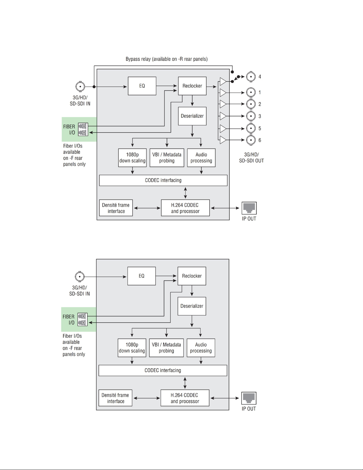
1.3 Functional Block Diagrams
Figure 1.1 SME-1901 Functional Block Diagram
Figure 1.2 SME-1911 Functional Block Diagram
2 | SME-1901 / 1911
Page 7
GUIDE TO INSTALLATION AND OPERATION
Select Button
IRD-3802
Status LED
St
atu
s
Select
SME-1901
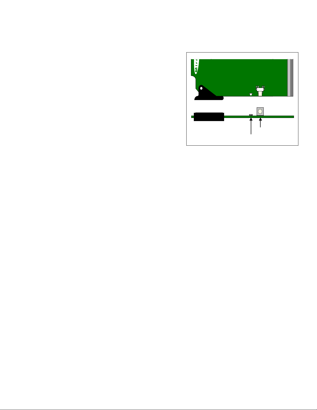
1.4 Front Card-edge Interface
The front card-edge of the SME-1901/1911
incorporates two elements:
• Status LED (see section 3.2)
• Select Button (see section 4)
The card extraction lever indicates the type of card that is installed
(SME-1901 shown).
Figure 1.3 Front card-edge layout
SME-1901 / 1911 | 3
Page 8
GUIDE TO INSTALLATION AND OPERATION
2 Installation
2.1 Installation of Rear Connector Panels
Grass Valley Densité-series cards are each associated with a rear connector panel, which must be installed in the
Densité frame before the card can be inserted.
The SME-1901/1911 card is sized to fit into Grass Valley’s Densité-2 frame, but can be ordered with an extender to fit
the taller Densité-3 frame. Rear panels are available for each frame type. SME-1901 and SME-1911 cards use
different rear panels, as the SME-1901 rears include the DA outputs and optional bypass relay which are not included
in the SME-1911.
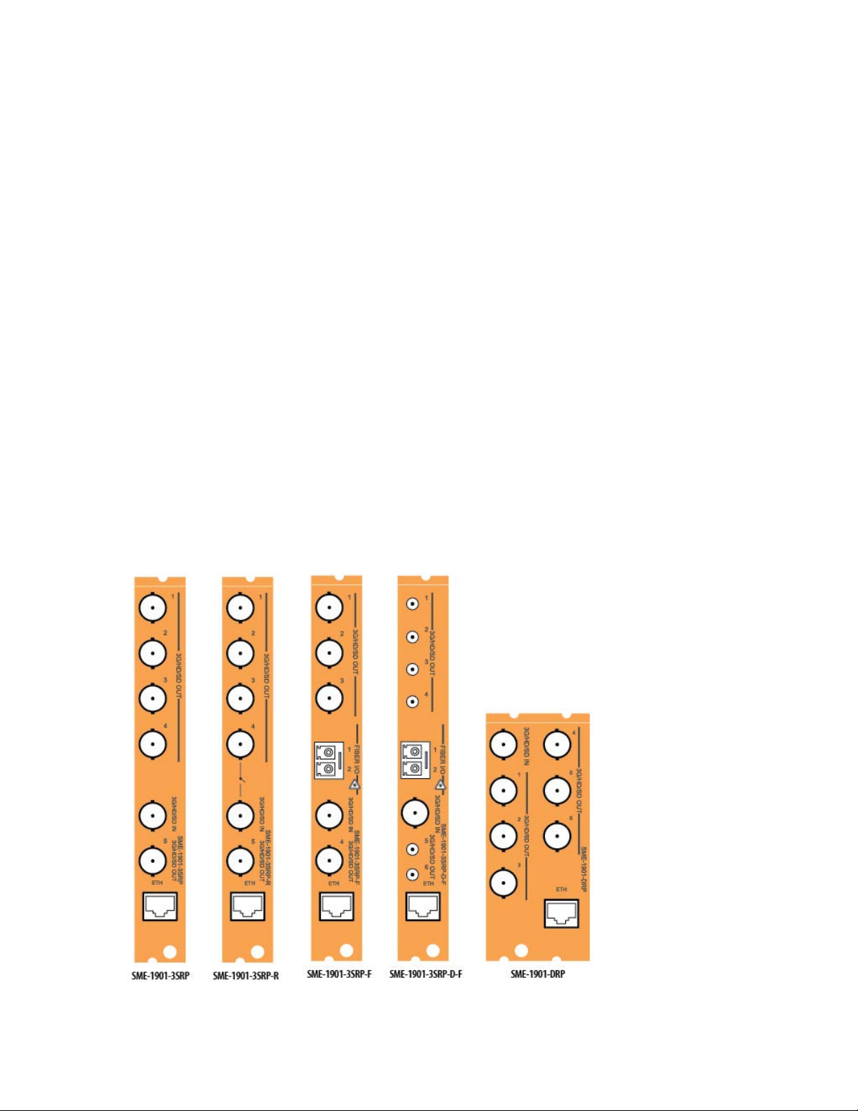
SME-1901 rear connector panels:
• SME-1901-DRP Densité-2 - Double-slot-width panel with 1x6 DA
• SME-1901-3SRP Densité-3 - Single-slot-width panel with 1x5 DA
• SME-1901-3SRP-R Densité-3 - Single-slot-width panel with 1x5 DA and bypass relay
• SME-1901-3SRP-F Densité-3 - Single-slot-width panel with 1x4 DA and fiber I/O support
• SME-1901-3SRP-D-F Densité-3 - Single-slot-width panel with 1x6 DA, DIN connectors and fiber I/O support
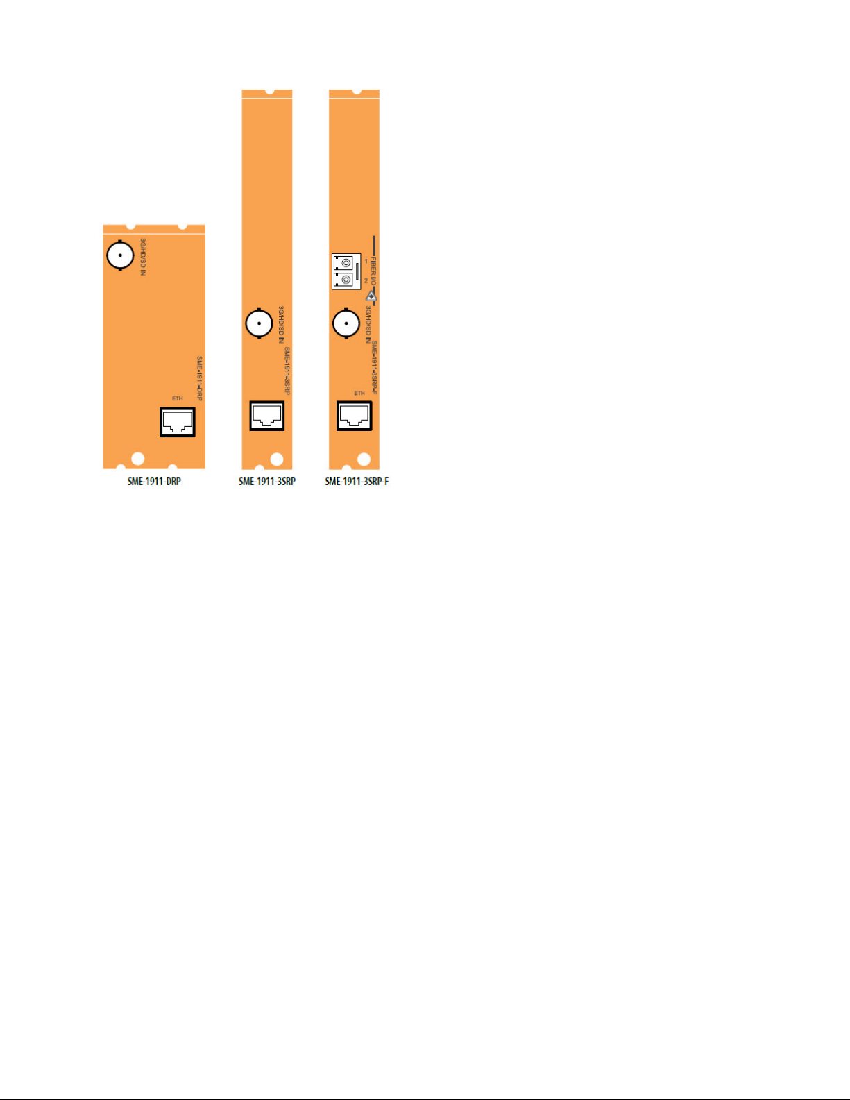
SME-1911 rear connector panels:
• SME-1911-DRP Densité-2 - Double-slot-width panel
• SME-1911-3SRP Densité-3 - Single-slot-width panel
• SME-1911-3SRP-F Densité-3 - Single-slot-width panel with fiber I/O support
See section 2.3 for details of the signal connections available on each of these connector panel types.
Rear panels are not interchangeable between the SME-1901 and the SME-1911
All cards and rear panels can be installed with the frame power on. The card has connectors which plug into a midframe mother board for distribution of power and for connection to the controller card, and a second connector which
plugs directly into the rear connector panel for input and output.
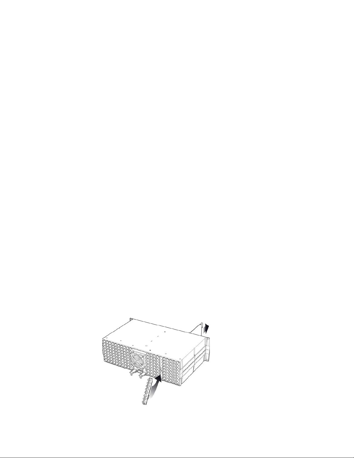
The rear connector panel must be installed with the card out of the frame.
• To remove an existing card from the slot, tilt up the swivel handle on the front of the card to lever the connectors
apart, then use the handle to pull the card straight out of the slot.
Figure 2.1 Densité-3 frame – rear panel installation
4 | SME-1901 / 1911
Page 9
GUIDE TO INSTALLATION AND OPERATION
To install the connector panel (Densité 2 and Densité 3 frames):
1. If a card is installed in the slot whose rear panel is being changed, remove it as described above.
2. Remove the existing panel (either blank or belonging to an existing card that is being changed) by releasing the
captive screw(s) at the bottom.
3. Position the new panel and secure it in place with the captive screw(s) at the bottom.
2.2 Card Installation
Once a matching rear connector panel has been installed, install the SME-1901/1911 card as follows:
1. Open the front panel of the frame.
2. Slide the SME-1901/1911 card into the slot and push gently on the handle to seat the connectors.
• For the double-slot-width rear panels used in Densité 2 frames, insert the card into the right-most slot, as
seen from the front of the frame. If the card is inserted into the wrong slot, the status LED on the front of the
3. Close the front panel of the frame.
card will flash red. The card will not be damaged.
2.3 Rear Panels and Connectors
2.3.1 Images of rear connector panels
The available rear panels for the SME-1901 and the SME-1911 are shown in the figures below, and their various
inputs and outputs are described.
Figure 2.1 SME-1901 Rear Panels
SME-1901 / 1911 | 5
Page 10
GUIDE TO INSTALLATION AND OPERATION
Figure 2.2 SME-1911 Rear Panels
2.3.2 Rear Panel Signal Connections
3G/HD/SD IN – Serial digital 3G/HD/SD input
Connect a serial digital vide o signal, conforming to the SMPTE ST424M standard for 3G input signals, SMPTE 292M
standard for HD input signals or SMPTE 259M standard for SD input signals, to the BNC labeled 3G/HD/SD IN. The
SME-1901 will automatically switch to the detected line/frame rate format.
3G/HD/SD OUT – Serial digital video outputs (SME-1901 only)
The SME-1901 provides up to six 3G/HD/SD SDI video outputs on BNC or DIN 1.0/2.3 connectors, labeled 3G/HD/SD
OUT 1 to 6. The SDI video signal conforms to the SMPTE ST424M, SMPTE 292M or SMPTE 259M-C standard. The
same signal is carried on all outputs.
ETH
Ethernet port, supporting 100 Mbps full or half-duplex Ethernet, and Autonegotiate, on an RJ-45 connector.
Fiber I/O (-F rear panels only)
Fiber connection via an SFP module. Use either a single-fiber receiver or a single-fiber transmitter module (1310
nm) and connect the fiber using an LC/PC connector.
6 | SME-1901 / 1911
Page 11

GUIDE TO INSTALLATION AND OPERATION
The LED will always show the most
Error Condition
Status LED
Green
Yellow
Red
Red
3 User Interface
3.1 Control options
The SME-1901/1911 can be controlled in three diff erent ways:
• The local control panel and its push-buttons can be used to move through a menu of parameters and to adjust a
basic set of parameters (see section 4).
• Grass Valley’s iControl system can be used to access the card’s operating parameters from a remote computer,
using a convenient graphical user interface (GUI) (see section 5).
• Grass Valley’s RCP-200 panel (consult factory for availability).
3.2 Card-Edge Status LED
The status monitor LED is located on the front card-edge of the SME-1901/1911, and is visible through the front
access door of the DENSITÉ frame. This multi-color LED indicates the status of the SME-1901 by color, and by
flashing/steady illum inati on.
The chart shows how the various error conditions that can be flagged on the SME-1901/1911 affect the LED state.
• If a cell is gray, the error condition cannot cause the LED to assume that state.
• If more than one LED state is possible for a particular error condition, the state is configurable.
See Section 5.10 for details.
• The factory default state is shown by a
severe detected error status that it is
configured to display, and in the chart
error severity increases from left to
right, with green representing no
error/disabled, and flashing red the
most severe error.
If the LED is Flashing Yellow, it
means that the card is selected for
local control using the Densité frame’s
control panel. See Section 4 for
details.
Rear/SFP missing
No SFP
Electrical input – no carrier
Optical Input – no carrier
Electrical input – no lock
Optical input – no lock
SFP receiver – power warning
SFP receiver – power error
SFP temperature error
Flashing
SME-1901 / 1911 | 7
Page 12
GUIDE TO INSTALLATION AND OPERATION
Figure
4 Local control using the Densité frame c ontrol panel
4.1 Overview
Push the SELECT button on the SME-1901/1911 card
edge (see Section 1.4) to assign the local control panel
to operate the SME-1901/1911. Use the control panel
buttons to navigate through the menu, as described
below.
All of the cards installed in a Densité frame are
connected to the frame’s controller card, which handles
all interaction between the cards and the outside world.
There are no operating controls located on the cards
themselves. The controller supports remote operation
via its Ethernet ports, and local operation using its
integrated control panel.
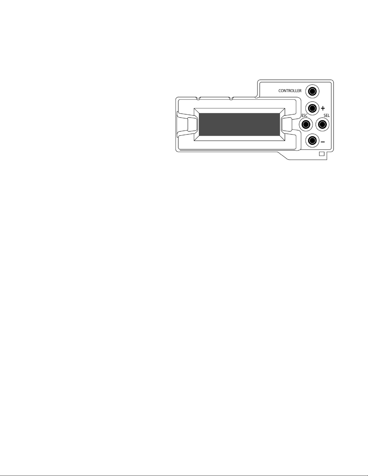
The local control panel is fastened to the front of the
CPU-ETH2 controller card, and when installed is
located in the front center of the frame, positioned in front of the power supplies. The panel consists of a display unit
capable of displaying two lines of text, each 16 characters in length, and five pushbuttons.
The panel is assigned to operate any card in the frame by pushing the SELECT button on the front edge of that card.
• Pushing the CONTROLLER button on the control panel selects the Controller card itself.
• The STATUS LED on the selected card flashes yellow.
The local control panel displays a menu that can be navigated using the four pushbuttons located beside the display.
The functionality of the pushbuttons is as follows:
[+] [–] Used for menu navigation and value modification
[SELECT] Gives access to the next menu level. When a parameter value is shown, pushing this button once
enables modification of the value using the [+] and [–] buttons; a second push confirms the new value
[ESC] Cancels the effect of parameter value changes that have not been confirmed; pushing [ESC] causes the
parameter to revert to its former value.
Pushing [ESC] moves the user back up to the previous menu level. At the main menu, [ESC] does not
exit the menu system. To exit, re-push the [SELECT] button for the card being controlled.
If no controls are operated for 30 seconds, the controller reverts to its normal standby status, and the selected card’s
STATUS LED reverts to its normal operating mode.
4.2 Menu for local control
The SME-1901/1911 has operating parameters which may be adjusted locally at the controller card interface.
• Press the SELECT button on the SME-1901 front card edge to assign the Densité frame’s local control panel
to the SME-1901/1911.
• Use the keys on the local control panel to step through the displayed menu to configure and adjust the SME-
1901/1911.
The complete menu structure is shown in Annex 1 to this document, beginning on page 27.
4.1 Densité Frame local control panel
8 | SME-1901 / 1911
Page 13

GUIDE TO INSTALLATION AND OPERATION
3
Figure
5 Remot e c ont rol using iControl
The operation of the SME-1901/1911 may be controlled using Grass Valley’s iControl system.
• This manual describes the control pan els ass oci ated w ith the SME-1901/1911 and their use.
• Please consult the iControl User’s Guide for information about setting up and operating iControl.
In iControl Navigator or iControl Websites, double-click on the SME-1901/1911 icon to open the control panel.
5.1 The iControl graphic interface window
The basic window structure for the SME-1901/1911 is shown in figure 5.1. The window identification line gives the
card type (SME-1901 or SME-1911) and the slot number where the card is installed in its Densité frame.
There are three main sections in the window itself, identified in figure 5.1:
Section 1. The top section displays eight icons on the left. These icons report different statuses such as card
communication status, input and output signal status, card health, etc. In some instances, they relate to conditions
defined through parameters settings.
5-1 SME-1901/1911 iC ontr o l graphic inter fac e wind ow
Icon # 1 2 3 4 5 6 7 8
Move the mouse over an icon and a status message appears below the icon providing additional information.
If there is an error, the error status message appears in the message area without mouse-over.
• If there are multiple errors, the error messages cycle so all can be seen
• The icon whose status or error message is shown is highlighted with a mauve background
SME-1901 / 1911 | 9
Page 14

GUIDE TO INSTALLATION AND OPERATION
The table below describes the various status icons that can appear, and how they are to be interpreted.
• In cases where there is more than one possible interpretation, read the error message in the iControl window to
see which applies.
Table – iControl Status Icon interpretation
Icon #1 – Manual Card Configuration
Remote card control activated. The iControl interface can be used to operate the card
(green)
Local card control active, The card is being controlled using the Densité frame control
panel, as described in section 4. Any changes made using the iControl interface will have
(yellow)
no effect on the card.
Icon #2 – Electrical Input (IN 1) Status
Carrier detected and locked
(green)
• Mouse over the icon to see format details.
Carrier detected
(yellow)
Signal absent
(red)
No rear
Optical input selected.
(gray)
Icon #3 – Optical Input (IN 2) Status
Carrier detected and locked.
(green)
• Mouse over the icon to see format details
Carrier detected
(yellow)
Signal absent
(red)
No rear
Electrical input selected.
(gray)
10 | SME-1901 / 1911
Page 15

Icon #4 – Main Output Status
(gray)
Status OK
(green)
• Mouse over the icon to see format and bitrate details
Disabled
Icon #5 – Proxy Output Status
Status OK
(green)
• Mouse over the icon to see format and bitrate details
Disabled
(gray)
Icon #6 – Operation Mode Status
GUIDE TO INSTALLATION AND OPERATION
Operation mode: Process – normal processing of the input signal
(green)
Operation mode: Color Bars – place the color bars and tone test pattern on the streaming
output.
(yellow)
Operation mode: Lipsync – place the lipsync test pattern on the streaming output.
(yellow)
Icon #7 – Ethernet Status
Ethernet Status: Link OK
(green)
• Mouse over the icon to see the Ethernet connection mode:
Autonegotiate/100 Base-TX FD/100 Base-TX HD
Ethernet status: No link
(red)
Icon #8 – Health Monitoring
(green)
(red)
Hardware OK
Hardware Health Monitoring - Hardware fault detected
If this icon appears red, return the card to Grass Valley and specify the error code.
SME-1901 / 1911 | 11
Page 16

GUIDE TO INSTALLATION AND OPERATION
Figure
Section 2. The left portion of the window contains a series of buttons, which become highlighted when they are
selected; the main panel (3) then displays the group’s set of parameters. Each of the groups is described in detail
below.
Section 3. The main panel contains all the parameters specific to the group selected. It may contain several tabs to
help manage the different parameters.
Each of the panels assoc iated with the groups access ed from the buttons in Section 2, and show n in Section 3, is
described individually in the following sections.
5.2 Status and Input panel
Input – Channel
Use the radio buttons to select the signal source:
• Electrical – IN 1, via BNC connector on the rear
panel
• Optical – IN 2, via the fiber input connector on the
rear panel.
This is only available with a –F rear panel and an
appropriate SFP module installed.
Input – Status
This section of the panel shows the status of the two inputs,
and also the video format detected on the selected input
Input – Reclocker
Use the radio buttons to select whether the reclocker is ON
or bypassed.
Input – Electric al B i tr ate
The icons in this area show the detected input bitrate, which
will be one of three known values for specific video formats,
or unknown if none of these matches.
[Unknown, 270 Mb/s, 1485 Mb/s, 2970 Mb/s]
SFP Info
The table of values identifies the SFP module installed in the rear panel, if supported and installed:
Type
Part Number
Serial Number
Date Code:
Temperature (C)
Voltage (V)
Optical Power (dBm)
Wavelength (mm)
Note that if the user installs an SFP module with two channels, a warning will appear at the bottom of the panel to
advise that only channel 1 is supported.
5-2 Status and Input panel
12 | SME-1901 / 1911
Page 17

GUIDE TO INSTALLATION AND OPERATION
Figure
Figure
5.3 Video Metadata panel
This panel reports on m etadat a det ect ed in the incoming
video.
Closed Captioning
The icon shows the presence (green) or absence (red) of
closed captioning data.
Timecode
Status icons flag the presence of two time code formats:
• DVITC/ATC-VITC
• ATC/LTC
AFD
The presence, and details if detected, of three types of AFD
data are shown:
• AFD
• VLI
• WSS
5-3 Video Metadata Panel
Teletext
The presence of teletext data for page 1 and page 2 (actual page numbers are shown in the data boxes) is shown by
the Presence and Subtitle icons.
5.4 Dolby Metadata panel
Input Status
The presence of Dolby Metadata in the input video is
flagged by the Input Status icon – green if present, red if
absent.
Source
Source – The source pulldown in this version of the card is
fixed at Video.
Line – use the pulldown to select between Auto detect and
a specific line.
SDID – use the pulldown to select a value between 1 and
9
5-4 Dolby Metadata panel
SME-1901 / 1911 | 13
Page 18

GUIDE TO INSTALLATION AND OPERATION
Figure
5.5 Audio Processing panel
Group Detected
The four icons indicate which audio groups have been
detected on the active input.
• Green icon = audio group present
Audio Type Status
The 16 icons show the type of audio input present on the
input audio pairs, identified by text and icon color:
• PCM – orange icon
• Non-PCM – yello w ic on
• AC3 – pink icon
• Dolby E – blue icon
Downmix – Input Channels
The six pulldowns allow the user to assign any of the 16
audio inputs to the downmix source channels:
• Left
• Right
• Center
• LFE
• Ls
• Rs
Downmix – Manual Downmix Config
Use the pulldowns to set up the details of the downmix:
Oper Mode – select the downmix operating mode
• Manual Use the other four pulldowns in this section to set up the downmix properties
• Follow Metadata Use the metadata in the incoming program to set up the downmix properties
In this mode, the other four pulldowns are inactive, but show the values derived from the
metadata (if present) that are being used for the downmix.
Mode – select the type of downmix you want:
• LtRt: Enables the downmix of 5.1 channels into an LtRt (Left total Right total) matrix surround encoded
stereo pair.
• LoRo: Enables the downmix of 5.1 channels into an LoRo (Left only Right only) stereo pair, which is a
conventional stereo signal.
5-5 Audio Processing panel
14 | SME-1901 / 1911
Page 19

GUIDE TO INSTALLATION AND OPERATION
Surround
Level
Center
Level
+
+
+
+
+
+
+
Ls
Rs
Lo
Ro
L
R
C
Surround
Level
+
LFE
Level
+
+
+
+
LFE
+
+
+
+
–
+
+
+
Surround
Level
L
C
R
LFE
Ls
Rs
Lt
Rt
+
+
Center
Level
+
+
LFE
Level
+
+
Center Mix Level – sets the center channel downmix level to the selected value
[+3 dB, +1.5dB, 0 dB, -1.5 dB, -3 dB, -4.5 dB, -6 dB, Mute]
Surround Mix Level – sets the surround channels (Ls & Rs) downmix level to the selected value
[+3 dB, +1.5dB, 0 dB, -1.5 dB, -3 dB, -4.5 dB, -6 dB, Mute]
LFE Mix Level – sets the LFE channels downmix level to the selected value.
[+10 dB, +9 dB, +7.5, +6 dB, +4.5 dB, +3 dB, +1.5dB, 0 dB, -1.5 dB, -3 dB, -4.5 dB, -6 dB, Mute]
The block diagrams below show the configuration of the LtRt surround sound downmixer and the LoRo stereo
downmixer.
Figure 5-6 LtRt Surround Sound Downmixer
Figure 5-7 LoRo Stereo Downmixer
SME-1901 / 1911 | 15
Page 20

GUIDE TO INSTALLATION AND OPERATION
Figur
Figure
5.6 Codec Config panel
This panel controls the output coding process.
Audio Codec
Use the radio buttons to select whether the output audio
channels are those selected in the Left and Right
pulldowns (in the range 1 to 16), or the output of the
downmixer (see the Audio Proc es sing pan el) .
Audio Codec - Encoding
Use the pulldown to select the audio encoding scheme:
• MPEG 1 L2@ 256 kbps
• AAC @ 128 kbps
Note: the MPEG 1 L2 bitrate is 256 kbps instead of 128
kbps as displayed in the interface.
Video Codec – Force progressive mode encoding
The video encoder normally defaults to interlaced mode for
interlaced formats and progressive mode for progressive
formats. Some decoders cannot decode a stream encoded
in interlaced mode. If this is the case, Force Progressive
Mode Encoding should be checked. Forcing this mode for
interlaced formats may cause artifacts, particularly in film-originated content.
Test Pattern (Streaming output only)
The pulldown allows the user to select an internally-generated test signal to replace the program signal at the SME1901/1911 streaming output.
OFF: the program signal appears at the output, and test signals are OFF
Color Bars and Tone: sends a 75% color bar test pattern (100% white), along with audio test tones (a
continuous tone on right channel with pulsed tone on left channel) to the SME-1901/1911 output.
Lip Sync: sends a special test signal comprising color bars and tone plus a detectable element that is used to
align audio-video dela ys in a processing path.
• The special test signal consists of 75% color bars within which a white square is inserted every 4 seconds for
a duration of 10 frames. Simultaneously with the beginning of the first field of video containing the white
square, the 16 embedded audio channels and the 8 AES outputs are pulsed with a tone lasting 250 ms.
5-8 Codec Config panel
e 5-9 Lip Sync test signal appearance and timing
16 | SME-1901 / 1911
Page 21

GUIDE TO INSTALLATION AND OPERATION
Figure
Presets
Select one of the available coding options for the Main and Proxy outputs, for 1080p/i, 720p and SD signals. The
available choices are shown in the chart:
Note: the 1080p/i Main “Medium” resolution is 1440x1080 instead of 1080x800 as displayed in the interface.
Video Main Output Proxy Output
1080p/i High (1920x1080 @ 5 Mbps)
Medium high (1920x1080 @ 3 Mbps)
Medium (1440x1080 @ 3 Mbps)
Low (960x540 @ 1 Mbps)
Disabled
720p High (1280x720 @ 5 Mbps)
Medium high (1280x720 @ 3 Mbps)
Low (960x540 @ 1 Mbps)
Disabled
SD
(525/625)
Restart Codec
Medium high (720x480 / 720x576 @ 2 Mbps)
Low (352x480 / 352x576 @ 1 Mbps)
Disabled
If the streaming output appears blocked or locked up after the input signal format changes, click this button to
restart the codec. It may take up to 100 seconds to resume streaming.
5.7 Streaming panel
This panel sets up the streaming output parameters, for
both Main and Proxy outputs.
Streaming Protocol
Use the pulldown to select the streaming mode that applies
to both Main and Proxy:
UDP/TS: This streaming mode allows the SME-19x1 to
stream raw TS over UDP.
• Unicast TS-over-UDP (raw TS carried over UDP
from a single source to a single destination)
• Multicast TS-over-UDP (raw TS carried over UDP
from a single source to multiple destinations)
RTP/TS: This streaming mode (or RTP packetization of
TS) allows the SM E-19x1 to stream any of four possible
streaming protocols, as follows:
Medium (480x288 @ 750 kbps)
Very l ow (256x160 @ 250 kbps)
Disabled
Medium (480x272 @ 750 kbps)
Very l ow (256x144 @ 250 kbps)
Disabled
Medium (352x256 / 352x288 @ 500 kbps)
Very l ow (128x96 / 128x96 @ 128 kbps)
Disabled
5-10 Streaming panel
SME-1901 / 1911 | 17
Page 22

GUIDE TO INSTALLATION AND OPERATION
• Unicast TS-over-UDP/RTP (raw TS carried over UDP from a single source to a single destination)
• Multicast TS-over-UDP/RTP (raw TS carried over UDP from a single source to multiple destinations)
• RTSP/TS-over-UDP/RTP (RTSP’s packetization of TS and carried over UDP)
• RTSP/TS-over-TCP (RTSP’s packetization of TS and encapsulated into an RT P-TCP connection)
The Main and Proxy streams each have the following parameters:
On/Off – use the pulldown to enable or disable the stream
IP address – enter the I P a ddres s of the destination. It is relevant for all connection types except RTPS/TS-over-
UDP/RTP and RTSP/TS-over-TCP.
Port – enter the port number ; valid port numbers are in the range 1024 to 65535.
After changing any of these parameters, you must click Apply for the changes to take effect, or Cancel to discard the
changes.
The decoder or set-top box will require a URL. It will have a different form depending on the chosen Streaming
Protocol. The following description gives examples for the Video LAN VLC Media Player software. Please refer to your
decoder or set-top box documentation.
Unicast TS-over-UDP and TS-over-UDP/RTP
<protocol>://@<unicast IP>:<port>
The <protocol> is either udp or rtp depending on the chosen Streaming Protocol. The <unicast IP> and <port> of the
destination is the Main or Proxy IP Address and Port from the Streaming Panel.
udp://@10.1.1.100:10000
rtp://@10.1.1.100:10002
Multicast TS-over-UDP and TS-over-UDP/RTP
<protocol>://<source IP>@<multicast IP>:<port>
The <protocol> is either udp or rtp depending on the chosen Streaming Protocol. The <source IP>, if it is used, is
the card’s IP Address from the Network Settings panel. This will depend on the IGMP configuration in the network
equipment (switch or router). The <multicast IP> and <port> is the Main or Proxy IP Address and Port from the
Streaming Panel.
• No IGMP
udp://@239.1.1.100:10000
rtp://@239.1.1.100:10002
• IGMP Any Source Multicast (ASM)
udp://0.0.0.0@239.1.1.1:10000
rtp://0.0.0.0@239.1.1.1:10002
• IGMP Specify Source Multicast (SSM)
udp://192.168.0.1@239.1.1.1:10000
rtp://192.168.0.1@239.1.1.1:10002
RTSP/TS-over-UDP/RTP and RTSP/TS-over-TCP
Main stream: rtsp://<card IP>/hiProxy
18 | SME-1901 / 1911
Page 23

GUIDE TO INSTALLATION AND OPERATION
Figure
Figure
Proxy stream: rtsp://<card IP>/loProxy
The <card IP> is the card’s IP Address from the Network Settings panel.
During the RTSP session, the card will also send a Unicast/Multicast RTP stream to the destination located at the IP
Address from the Streaming Panel. If this is not required, set the IP Address to 0.0.0.0.
5.8 Network Settings panel
This panel sets up the IP address of this card on the
Ethernet.
IP Config
Type values directly into the data boxes for IP address,
Mask and Gateway.
• Obtain the appropriate addresses from your IT
department as required.
If you have made changes, you must click Apply for the
changes to take effect, or Cancel to discard the changes.
Ethernet
Use the pulldown to select the speed of the ethernet
connection:
• Autonegotiate
• 100 Base-TX FD [Full Duplex]
• 100 Base-TX HD [Half Duplex]
The status icon is green when the ethernet is connected.
5-11 Network Settings panel
5.9 Factory/Presets panel
Factory
Load Factory: Clicking this button will restore the card to a
factory default state.
• Note that User Presets are not changed
User Presets
The SME-1901 and SME-1911 have memory registers
which can hold up to 5 user-defined parameter settings.
Select any one of the five pr eset s using the pu ll-d o wn list.
The name of the currently-selected User Preset is shown
on the pulldown box.
Click Load to load the contents of the selected User Preset
into the SME-1901 or SME-1911. All parameter settings
and values will be replaced by the contents of the selected
User Preset.
5-12 Factory / Presets panel
SME-1901 / 1911 | 19
Page 24

GUIDE TO INSTALLATION AND OPERATION
Figure 5-13
Figure
Click Save to store the current parameter settings and values from the SME-1901 or SME-1911 into the selected User
Preset. The existing contents of the preset will be overwritten.
Profiles
This section provides the option to save and recover the entire card configuration (including user presets if desired) on
an external disk, or to copy it to another SME-1901 or SME-1911 card.
Note: although the SME-1901 and SME-1911 are very similar in most aspects of their operation, the profiles for
these cards are NOT interchangeable, and you must use the card-specific file in the following procedure.
Click on Profiles to open the Profile Copy window.
Profile Copy window
Copy profile from
This line shows this SME-1901 or SME-1911 card, and identifies it by App server, Densité frame and slot number,
card type and firmware version.
The Profile column has a pulldown that allows you to select
which profiles you will work with, and gives these choices:
• Current, User1, User2, User3, User4, User5, All
The Select column includes a checkbox (preselected checked)
to confirm that you want to work with the current card.
Save Profile to Disk…
Click this button to open a Save dialog allowing you to specify a
file name and location to which the selected profiles for this card
will be saved.
Hint - It is a good idea to create a folder for these files, because
they are not explicitly identified as SME-1901 or SME-1911
5-14 Save Profile to Disk dialog
profiles, and will be difficult to find and identify if not clearly
named and conveniently located.
20 | SME-1901 / 1911
Page 25

GUIDE TO INSTALLATION AND OPERATION
Figure
• Click the save button once the name and location have been identified in the Save box
• If the file is saved correctly, the Transfer Status box on the right of the Copy profile from line w il l indicate
Succeeded against a green background.
• If the file was not saved for some reason, the Transfer Status box to the right of the Copy profile from line will
indicate Failed against a red background
Restore profiles from disk…
Click this button to open an Open dialog box within which you
can locate and select a valid SME-1901 or SME-1911 profile
file.
• Click Open to read the contents of the file and to
reconfigure this SME-1901’s or SME-1911’s profiles
according to its contents
• While the reconfiguration is in progress, the Transfer
Status box on the right of the Copy profile from line will
indicate Working against a yellow background
• When the reconfiguration is complete, the Transfer Status
box on the right of the Copy profile from line will indicate
Succeeded against a green background
Copy profile to section
5-15 Restore Profiles from Disk dialog
This line shows other SME-1901 or SME-1911 cards that are available on the iControl network, each identified by App
server, Densité frame and slot number, card type and firmware version.
The Profile column shows the same information as is shown for the current card in the Copy profile from line, i.e. one
of the following:
• Current, User1, User2, User3, User4, User5, All
The Select column includes a checkbox to identify which SME-1901 or SME-1911 cards you wish to cop y profiles int o
from the current card.
• For convenience, a Select all checkbox is provided in the column header.
Click Copy to copy the selected profiles from this card into the selected other SME-1901 or SME-1911 cards.
• While the profile copy operation is in progress, the Transfer Status box on the right of the Copy profile to line w il l
indicate Working against a yellow background.
• When the profile copy operation is complete, the Transfer Status box on the right of the Copy profile to line will
indicate Succeeded against a green background.
5.10 Alarm Config panel
This panel allows the alarm reporting of the SME-1901/1911 to be configured. The panel opens in a new window
when the button is clicked, and can be resized if needed.
SME-1901 / 1911 | 21
Page 26

GUIDE TO INSTALLATION AND OPERATION
Figure
The panel is organized in columns.
Status/Name
This contains an expandable tree listing all the
alarms reported by this SME-1901/1911 card.
• Each alarm name includes an icon that
shows its current status
• Some alarms may be text-only and the
alarm status is shown in the name and not
by a status icon
The Card LED, Overall alarm and GSM
contribution columns contain pulldown lists that
allow the level of contribution of each individual
alarm to the alarm named in the column heading
to be set.
Cli ck on the alarm icon to
see the available levels;
then click on one to select it
Card LED
This column allows configuration of the
contribution of selected individual alarms to the
status LED located on the front card edge. The
Card LED status is shown at the bottom of the
alarm tree in the Status/Name column.
Overall Alarm
This column allows configuration of the
contribution of each individual alarm to the Overall
Alarm associated with this card. The Overall
Alarm is shown in the upper left corner of the
5-16 Alarm Co nfiguration panel
iControl panel, and also appears at the bottom of
the Status/Name column.
GSM Contribution
This column allows configuration of the contribution of each individual alarm to the GSM Alarm Status associated with
this card. GSM is a dynamic register of all iControl system alarms, and is also an alarm provider for external
applications. The possible values for this contribution are related to the Overall alarm contribution:
• If the Overall alarm contribution is selected as Disabled, the GSM alarm contribution can be set to any available
value
• If the Overall alarm contribution is selected as any level other than disabled, the GSM contribution is forced to
follow the Overall Alarm.
22 | SME-1901 / 1911
Page 27

GUIDE TO INSTALLATION AND OPERATION
Figure
Figure
Levels associated with these alarms:
The pulldown lists may contain some or all of the following options:
The alarm makes no contribution (black icon)
The alarm is of minor importance (yellow icon)
The alarm is of major importance (orange icon)
The alarm is of critical importance (red icon)
The alarm exists but has no effect (used for text and composite alarms)
Shortcut: if you click in one of the Set All boxes beside a section heading, you will open a pulldown that lets you
assign a level to all alarms in that section of the column simultaneously.
Once the alarms are configured, you may accept the changes or discard them:
Log Events
iControl maintains a log of alarm events associated with the card. The log is useful for troubleshooting and identifying
event sequences. Click in the checkbox to enable logging of alarm events for each individual alarm.
At the bottom of the window are several other controls
Overall alarm and GSM contribution follow card LED
Click in the checkbox to force the Overall alarm and GSM
contribution to be identical to the Card LED status
• All Overall alarms and GSM contributions for which
there is a Card LED alarm will be forced to match the
Card LED alarm
• All Overall Alarms and GSM contributions for which
there is no Card LED alarm will be forced to Disabled
A warning box will open allowing you to confirm the action,
since it will result in changes to the configuration and there is
no undo function.
5-17 Warning for Follow LED change
Copy to other cards
Click this button to open a panel that allows the alarm
configuration set for this card to be copied into another SME1901/1911 card.
• Select one or more destination cards from the list in the
window by clicking in the checkboxes, or all of them by
clicking in the All checkbox
• Note that when you do a Copy Profile for this card (see
Sect.5.9), the alarm configuration is copied along with all
the other settings.
5-18 Copy to Other Cards window
SME-1901 / 1911 | 23
Page 28

GUIDE TO INSTALLATION AND OPERATION
Figure
Figure
Figure
Get alarm keys
Click this button to open a save dialog where you can save a
file containing a list of all alarms on this card and their current
values, along with an Alarm Key for each. The alarm keys are
useful for system integration and troubleshooting.
• The file is saved in .csv format
OK, Apply, Cancel
• OK accepts the settings and closes the window once the
card confirms that there are no errors.
• Apply accepts the settings, but leaves the window open
• Cancel closes the window without applying any changes,
and leaves the previous settings int ac t.
5-19 Get Alarm Keys dialog
5.11 Info panel
When the SME-1901 or SM E-1911 is included in an iControl
environment, certain information about the card should be
available to the iControl system. The user can enter labels
and comments that will make this card easy to identify in a
complex setup. This information is entered into data boxes
in the Info control panel.
Label: type the label that is shown for this
SME-1901/1911 when it appears in
iControl applications
Short Label type the short-form label that iControl
uses in some cases (8 characters)
Source ID type a descriptive name for SME-
1901/1911
Comments: type any desired text
The remaining data boxes show manufacturing information
about this card.
Three buttons in the panel give access to other inform at ion.
• Details…: Reports the Firmware version, service version, and panel version for
this card.
5-20 Info panel
5-21 Details window
24 | SME-1901 / 1911
Page 29

GUIDE TO INSTALLATION AND OPERATION
Figure
Figure
• Advanced…: Shows the Long ID for this card. The Long ID is the
address of this SME-1901/1911 in the iControl network.
• Remote System Administration – opens the Joining Locators window,
which lists remote lookup services to which this SME-1901/1911 is
registered
Add: Force the iControl service for this SME-1901/1911 to register
itself on a user-specified Jini lookup service, using the following
syntax in the data box:
jini://<ip_address>
where <ip_address> is the ip address of the server running the
lookup service, e.g.:
Remove: select one of the services listed in the window by clicking on it, and click Remove to open a query
box allowing you to delete it from the window.
5-22 Advanced window
5-23 Joining Locators window
SME-1901 / 1911 | 25
Page 30

GUIDE TO INSTALLATION AND OPERATION
6 Specifications
ELECTRICAL INPUT
Signal: 3Gbps/HD/SD-SDI SMPTE 424M, 292M, and 259M-C compliant
Supports data rates of: 270, 1483.5, 1485, 2967, 2 970 Mbps
Cable length * (Belden 1694A): 3 Gbps: 110 m (360 ft) at 3 Gbps
HD: 200 m (655 ft) at 1.5 Gbps
SD: 400 m (1310 ft) at 270 Mbps
Return loss *: >15 dB for up to 1.5 GHz
>10 dB from 1.5 GHz to 3 GHz
IP INPUT/OUTPUT
Quantity: 1
Connector: 100 Mbps Ethernet with RJ45 connector IEEE 802.3
PROCESSING PERFORMANCE: IP Streaming
Signal path: 8 bits
Compression: H.264 high profile (level 4.0)
Frame rate: Full rate of input signal – except 3G is half the rate
Bitrate: 256 Kb/s to 5 Mb/s
Audio encoding: AAC, MPEG-1 Layer II
ELECTRICAL OUTPUTS (6) (SME-1901 only)
Signal: 3Gbps/HD/SD-SDI SMPTE 424M, 292M, and 259M-C compliant
Supports data rates of: 270, 1483.5, 1485, 2967, 2970 Mbps
Return loss: >15 dB for up to 1.5 GHz
>10 dB from 1.5 GHz to 3 GHz
Jitter (wideband): HD/SD: <0.2 UI
3 Gbps: <0.3 UI
Rise / fall time: HD: 135 ps max., 20 % to 80 %
SD: 400 - 800 ps, 20 % to 80 %
PROCESSING PERFORMANCE: DA section (SME-1901 only)
Signal path: 10 bits
Latency: <6 ns
ELECTRICAL
Power: SME-1901 10 W
SME-1911 9 W
* Cable length and return loss specifications will be reduced when using the output protected by the bypass relay on
SME-1901-3SRP-R rears.
26 | SME-1901 / 1911
Page 31

GUIDE TO INSTALLATION AND OPERATION
7 Contac t Us
Grass Valley Technical Support
For technical assistance, contact our international support center, at
1-800-547-8949 (US and Canada) or +1 530 478 4148.
To obtain a local phone number for the support center nearest you, please consult the Contact Us section of Grass
Valley’s website (www.grassvalley.com).
An online form for e-mail contact is also available from the website.
Corporate Head Office
Grass Valley
3499 Douglas-B.-Floreani
St-Laurent, Quebec H4S 2C6
Canada
Telephone: +1 514 333 1772
Fax: +1 514 333 9828
www.grassvalley.com
:
SME-1901 / 1911 | 27
Page 32

GUIDE TO INSTALLATION AND OPERATION
Levels
1 2 3
Status/Parameters
Comments
STATUS
GENERAL
[SYS OK], [NO REAR / SME-1901-3SRP-F /
VIDEO INPUT
NO SIGNAL / NO LOCK / SD 525 / HD 1080i60
EMBEDDED AUDIO
GRP[1-4] [ABSENT / PRESENT]
DOLBY METADATA
ABSENT / program config
See Dolby documentation for the
NETWORK
DOWN / UP 100 [HD / FD] [AUTO]
MAC ADDRESS
aabb ccdd eeff
6 bytes in hex format
CONFIG
LOAD
USER 1, USER 2, USER 3, USER 4, USER 5
SAVE
USER 1, USER 2, USER 3, USER 4, USER 5
DA
INPUT
ELECTRICAL, OPT ICAL
RECLOCKER
BYPASS, ON
STREAMING
MAIN STREAM
ACTIVATION
OFF, ON
IP ADDRESS
xxx.xxx.xxx.xxx
default 239.1.1.1
PORT
xxxxx
default 1234
ANNEX 1 – SME-1901/1911 Local User Interface
SME-1901-3SRP-R / SME-1901-3SRP / SME1901-DRP-F / SME-1901-3SRP-D-F], [SFP [RX
| TX | MISMATCH], [TEST ENABLED]
/ HD 1080i59.94 / HD 1080p30 / HD 1080pSF30
/ HD 1080p24 / HD 1080pSF24 / HD 720p60 /
HD 720p59.94 / HD 720p30 / HD 720p24 / SD
480p / SD 525p / SD 525p 27MHz / 3G 1080p60
[A / B / B2] / 3G 1080p59.94 [A / B / B2] / SD
525 YC / GFX 1600x1200 60 / GFX 1920x1200
60 / SD 625 / HD 1080i50 / HD 1080p25 / HD
720p50 / HD 720p25 / SD 576p / SD 625p50 /
SD 625p50 27MHz / 3G 1080p50 [A / B / B2] /
UNKNOWN
list of program configs
28 | SME-1901 / 1911
Page 33

GUIDE TO INSTALLATION AND OPERATION
PROXY STREAM
ACTIVATION
OFF, ON
IP ADDRESS
xxx.xxx.xxx.xxx
default 239.1.1.1
PORT
xxxxx
default 1236
TEST PATTER N
OFF, COLOR BARS, LIP SYNC
CONFIGURE ALARMS
REAR/SFP MIS
LEVEL
GREEN, YELLOW, RED, FLASHING RED
REPORT
NONE, GPI
NO SFP
LEVEL
GREEN, YELLOW, RED, FLASHING RED
REPORT
NONE, GPI
ELECT NO CARRIER
LEVEL
GREEN, YELLOW, RED, FLASHING RED
REPORT
NONE, GPI
OPTIC NO CARRIER
LEVEL
GREEN, YELLOW, RED, FLASHING RED
REPORT
NONE, GPI
ELECT NO LOCK
LEVEL
GREEN, YELLOW, RED, FLASH ING RED
REPORT
NONE, GPI
OPTIC NO LOCK
LEVEL
GREEN, YELLOW, RED, FLASHING RED
REPORT
NONE, GPI
SFP RX PWR WARN
LEVEL
GREEN, YELLOW, RED, FLASHING RED
REPORT
NONE, GPI
SFP RX PWR ERROR
LEVEL
GREEN, YELLOW, RED, FLASHING RED
REPORT
NONE, GPI
SFP TEMP ERROR
LEVEL
GREEN, YELLOW, RED, FLASHING RED
REPORT
NONE, GPI
NETWORK SETTINGS
IP ADDRESS
xxx.xxx.xxx.xxx
default 192.168.3.31
NET MASK
xxx.xxx.xxx.xxx
default 255.255.255.0
GATEWAY
xxx.xxx.xxx.xxx
default 192.168.3.1
VERSION
X.Y.Z BUILD xxxxx
version X.Y.Z
FACTORY DEFAULT
RESTORE
restore parameters to underlined
values
SME-1901 / 1911 | 29
Page 34

GUIDE TO INSTALLATION AND OPERATION
ANNEX 2 – Upgrading the SME-1901 / SME-1911
The SME-1901/SME-1911 is designed to be upgraded without interrupting the card’s DA section.
Upgrading to a new firmware/software release is accomplished using the Densité Upgrade Manager that is available
in iControl Navigator (appserver) v5.0 and later and iControl Solo v6.0 and later . This method m a y not be possible
because of the network topology or restricted access to the site. If this is the case, an alternate method is now
available when the installed firmware version is 1.2.0 or later.
For a more complete discussion of this application, including functionality not included in this single-card upgrade
description, consult the following documents:
• iControl (appserver) v5.0 User Guide, document M226-9900-282 or later: “Working with Densité Upgrade
Manager” in the chapter “Configuring Devices and Services”
• iControl Solo v6.0 User Guide, document M786-1600-328 or later: “Working with Densité Upgrade Manager”
in the chapter “Using iCo ntr ol Solo”
The upgrade method will depend on the way the equipment is connected to the network. Whether using the
recommended or alternate method, the first step is to acquire the upgrade package file from Grass Valley and save it
on your computer. For version X.Y.Z, it will be named:
SME-1901-vXYZ-iControl_upgrade_package.zip (for SME-1901)
SME-1911-vXYZ-iControl_upgrade_package.zip (for SME-1911)
Recommended upgrade procedure:
The recommended method uses the Densité Upgrade Manager and takes approximately two minutes. It requires that
the Ethernet port on the card’s rear panel, normally used for streaming, be connected to the same subnetwork as the
iControl appserver or PC running iCont rol So lo. There are two configurations to choose from.
Configuration 1: on-site
Usually the appserver or PC is on the “control” network and the card streams on a separate “data” network.
Nevertheless, an upgrade can be performed in these conditions. With iControl Solo, use a PC with two network
interfaces, one connected to the same “control” network as the Densite frame, and the other to the same “data”
network as the card’s Ethernet port.
Configuration 2: off-site
If this is not possible, another option is to set up a separate environment for card upgrades. On a different local
network, connect a Densité frame, insert the cards to upgrade in this frame, connect their rear panel Ethernet ports
and finally connect the PC runn ing iCo ntr o l Solo or the iCon tr ol appserver. Ensure that the card’s Ethernet port can be
accessed since it is used for the upgrade procedure. This can be configured in the Network Settings pan el. Cl ick
Apply after modification.
30 | SME-1901 / 1911
Page 35

GUIDE TO INSTALLATION AND OPERATION
From here on, the term iControl will be used to designate iControl Navigator on the appserver of iControl Solo running
on a PC.
1. Open iControl linked to the frame containing the card you wish to upgrade and double-click on the SME1901/SME-1911 card’s icon to open its control panel
2. In the Streaming panel, turn both streaming ports OFF. This will
accelerate the upgrade procedure.
It is not necessary to set all the Codec presets to DISABLED in the
Codec Config panel.
3. Close the SME-1901/SME-1911 control panel by clicking the icon in the upper right corner.
4. In iControl, select Densite U pgrad e Mana ger from the Tools pulldown menu
5. In the Densite Upgrade Manager window, click Upload Files…
6. In the Open dialog, navigate to the upgrade file you saved, select it, and click Open. Then click Upload.
The selected file is uploaded, and saved on the appserver or PC. Click Close to return to the Densite Upgrade
Manager window.
SME-1901 / 1911 | 31
Page 36

GUIDE TO INSTALLATION AND OPERATION
7. Locate the card you wish to upgrade in the Densite Upgrade Manager window, and click the down-arrow in the
Available package column.
The pulldown list should include the new upgrade package that you uploaded to the appserver or PC in the
previous step.
Version XYZ appears in the list as:
X.Y.Z-RC-N (for SME-1901)
where N is the package’s Release number. This is only used to differentiate the package with a beta version that
may exist.
8. Click on the new upgrade package name in the Avail a ble pack age pulldown list.
• The selected name will appear in the available package column.
• The Select/Bypass checkbox will be selected for that card.
• The Install progress window will become active, showing 0.0%.
• The Installed package, Installed firmware and Installed software columns will show the upgrade path that is
proposed; i.e. the existing version, and the version that will replace it.
• The Upgrade button at the bottom of the Dens ite Upgrade Manager windo w will b ecome enabled.
Multiple SME-1901/SME-1911 cards can be upgraded simultaneously by selecting the upgrade package for each.
9. Click Upgrade
The Upgrade confirmation window appears. Click Yes.
Observe the Install Progr es s window to see the current status of the upgrade. While the upgrade is in progress,
the card LED is Yel low.
When the upgrade has been completed, the window will display the message “Upgrade succeeded” on a green
background.
Look at the Installed package, Installed firmware and Installed software columns to verify that the upgrade has
been correctly installed.
10. Close the Densite Upgrade Manager window by clicking the icon in the upper right corner.
11. In iControl, double-click on the updated SME-1901/SME-1911 card’s icon to open its control panel. Enable the
streaming ports that were previously disabled in step 2. If the IP address was modified for the upgrade, set it to
the previous IP address. The procedure is now complete for this card.
Alternate upgrade procedure:
If the recommended procedure is not possible, an alternate upgrade method exists when firmware version 1.2.0 or
later is already installed in the SME-1901/SME-1911. The procedure does not require the rear panel Ethernet port so
no changes have to be done to the equipment. This upgrade process will take approximately two hours per card.
Although the iControl card panel will not be available during the upgrade, the SME-1901/SME-1911 remains
functional until the end of the process at which time the card is automatically rebooted.
The software utility used to upgrade the SME-1901/SME-1911 is called Miranda Interface Updater. It is available in
iControl Navigator (appserver) v4.x, iControl Solo v4.x, or as a stand-alone Java application. Contact Grass Valley to
obtain the stand-alone application.
32 | SME-1901 / 1911
Page 37

GUIDE TO INSTALLATION AND OPERATION
The upgrade file used here is contained in the zip file obtained from Grass Valley. Before beginning the procedure
below, open the zip file and extract the file named:
firmware-X.Y.Z.B.zip
where X.Y.Z is the package version and B is the build number. This file is the upgrade package used in the procedure
below.
1. The Densité frame containing the SME-1901/SME-1911 card to upgrade must not be Online in the iControl
Densite Manager. If it is in the list, set it to Standby for the duration of the upgrade procedure.
2. Click Miranda Interface Updater in the Tools menu of iControl Navigator v4 or iControl Solo v4 or execute the
stand-alone version.
Enter the Densité frame’s IP address in the Densite IP
address box and click Connect.
Click Open and choose the upgrade package. The Upgrade
Version displayed will only display the X in the X.Y.Z version
number.
The SME-1901/SME-1911 cards in the frame will no longer
be grayed. It is now possible to select the cards to upgrade
using the checkboxes in the Select column.
3. Click Upgrade. A message box will appear with a cautionary statement. Click Yes to continue.
The process will take approximately two hours for each card. While the upgrade is in progress, the card icon is
Yellow.
When the upgrade has been completed for a card, the message “Upgrade Successful” on a green background
will be displayed in the Status column.
4. Close the Miranda Interface Updater window by clicking the icon in the upp er ri ght corner .
SME-1901 / 1911 | 33
 Loading...