

Page 1

SHED and HDX User Guide
M4047-9900-103
16 January 2015
Page 2

Notices
Copyright & Trademark Notice
Copyright © 2003–2015, Grass Valley. All rights reserved.
Belden, Belden Sending All The Right Signals, and the Belden logo are trademarks or
registered trademarks of Belden Inc. or its affiliated companies in the United States and
other jurisdictions. Grass Valley, SHED and HDX are trademarks or registered trademarks of
Grass Valley. Belden Inc., Grass Valley, and other parties may also have trademark rights in
other terms used herein.
Terms and Conditions
Please read the following terms and conditions carefully. By using SHED and HDX
documentation, you agree to the following terms and conditions.
Grass Valley, a Belden Brand (“Grass Valley”) hereby grants permission and license to owners
of SHED and HDX to use their product manuals for their own internal business use. Manuals
for Grass Valley products may not be reproduced or transmitted in any form or by any
means, electronic or mechanical, including photocopying and recording, for any purpose
unless specifically authorized in writing by Grass Valley.
A Grass Valley manual may have been revised to reflect changes made to the product
during its manufacturing life. Thus, different versions of a manual may exist for any given
product. Care should be taken to ensure that one obtains the proper manual version for a
specific product serial number.
Information in this document is subject to change without notice and does not represent a
commitment on the part of Grass Valley.
Warranty information is available in the Support section of the Grass Valley Web site
www.grassvalley.com).
(
Title SHED and HDX User Guide
Part Number M4047-9900-103
Revision 16 January 2015
ii
Page 3

Table of Contents
1 About SHED and HDX . . . . . . . . . . . . . . . . . . . . . . . . . . . . . . . . . . . 1
About SHED and HDX . . . . . . . . . . . . . . . . . . . . . . . . . . . . . . . . . . . . . . . . . . . . . . . . . . . . . . . . . . . . . 1
Product Returns . . . . . . . . . . . . . . . . . . . . . . . . . . . . . . . . . . . . . . . . . . . . . . . . . . . . . . . . . . . . . . . 1
About this User Guide . . . . . . . . . . . . . . . . . . . . . . . . . . . . . . . . . . . . . . . . . . . . . . . . . . . . . . . . . 1
Safety and Notices. . . . . . . . . . . . . . . . . . . . . . . . . . . . . . . . . . . . . . . . . . . . . . . . . . . . . . . . . . . . . . . . . 2
Laser Radiation. . . . . . . . . . . . . . . . . . . . . . . . . . . . . . . . . . . . . . . . . . . . . . . . . . . . . . . . . . . . . . . . 2
FCC Part A Manual Notice. . . . . . . . . . . . . . . . . . . . . . . . . . . . . . . . . . . . . . . . . . . . . . . . . . . . . . 2
Warning CE . . . . . . . . . . . . . . . . . . . . . . . . . . . . . . . . . . . . . . . . . . . . . . . . . . . . . . . . . . . . . . . . . . . 2
2 Installation and Configuration . . . . . . . . . . . . . . . . . . . . . . . . . . 3
Setting Up a System . . . . . . . . . . . . . . . . . . . . . . . . . . . . . . . . . . . . . . . . . . . . . . . . . . . . . . . . . . . . . . . 3
Passive Set-up - SHED-BS and SHED-C . . . . . . . . . . . . . . . . . . . . . . . . . . . . . . . . . . . . . . . . . 3
Active Set-up - SHED-BS and HDX . . . . . . . . . . . . . . . . . . . . . . . . . . . . . . . . . . . . . . . . . . . . . 3
SHED-BS Configuration for Camera Types. . . . . . . . . . . . . . . . . . . . . . . . . . . . . . . . . . . . . . 4
SHED-C and PANASONIC 3800 Camera . . . . . . . . . . . . . . . . . . . . . . . . . . . . . . . . . . . . . . . . 4
Setting Up HDX . . . . . . . . . . . . . . . . . . . . . . . . . . . . . . . . . . . . . . . . . . . . . . . . . . . . . . . . . . . . . . . . . . . 5
Changing the Input Voltage . . . . . . . . . . . . . . . . . . . . . . . . . . . . . . . . . . . . . . . . . . . . . . . . . . .5
Selecting Normal or Low line voltage range . . . . . . . . . . . . . . . . . . . . . . . . . . . . . . . . . . . . 5
Setting up SHED and SHED-6 . . . . . . . . . . . . . . . . . . . . . . . . . . . . . . . . . . . . . . . . . . . . . . . . . . . . . . 7
Fiber Connectors . . . . . . . . . . . . . . . . . . . . . . . . . . . . . . . . . . . . . . . . . . . . . . . . . . . . . . . . . . . . . . 8
3 SHED and HDX Features. . . . . . . . . . . . . . . . . . . . . . . . . . . . . . . . . 9
System Operation . . . . . . . . . . . . . . . . . . . . . . . . . . . . . . . . . . . . . . . . . . . . . . . . . . . . . . . . . . . . . . . . . 9
HDX. . . . . . . . . . . . . . . . . . . . . . . . . . . . . . . . . . . . . . . . . . . . . . . . . . . . . . . . . . . . . . . . . . . . . . . . . . . . . .10
Accessory List . . . . . . . . . . . . . . . . . . . . . . . . . . . . . . . . . . . . . . . . . . . . . . . . . . . . . . . . . . . . . . . .11
HDX Rack Mount Frame . . . . . . . . . . . . . . . . . . . . . . . . . . . . . . . . . . . . . . . . . . . . . . . . . . . . . .12
SHED-BS . . . . . . . . . . . . . . . . . . . . . . . . . . . . . . . . . . . . . . . . . . . . . . . . . . . . . . . . . . . . . . . . . . . . . . . . .13
Description . . . . . . . . . . . . . . . . . . . . . . . . . . . . . . . . . . . . . . . . . . . . . . . . . . . . . . . . . . . . . . . . . .13
Connectors. . . . . . . . . . . . . . . . . . . . . . . . . . . . . . . . . . . . . . . . . . . . . . . . . . . . . . . . . . . . . . . . . . .14
Deployment. . . . . . . . . . . . . . . . . . . . . . . . . . . . . . . . . . . . . . . . . . . . . . . . . . . . . . . . . . . . . . . . . .14
SHED-C . . . . . . . . . . . . . . . . . . . . . . . . . . . . . . . . . . . . . . . . . . . . . . . . . . . . . . . . . . . . . . . . . . . . . . . . . .15
Application . . . . . . . . . . . . . . . . . . . . . . . . . . . . . . . . . . . . . . . . . . . . . . . . . . . . . . . . . . . . . . . . . .15
Connectors. . . . . . . . . . . . . . . . . . . . . . . . . . . . . . . . . . . . . . . . . . . . . . . . . . . . . . . . . . . . . . . . . . .15
Deployment. . . . . . . . . . . . . . . . . . . . . . . . . . . . . . . . . . . . . . . . . . . . . . . . . . . . . . . . . . . . . . . . . .16
Troubleshooting . . . . . . . . . . . . . . . . . . . . . . . . . . . . . . . . . . . . . . . . . . . . . . . . . . . . . . . . . . . . . . . . .16
A Note About Fiber Maintenance . . . . . . . . . . . . . . . . . . . . . . . . . . . . . . . . . . . . . . . . . . . . . . . . .17
Block Diagram . . . . . . . . . . . . . . . . . . . . . . . . . . . . . . . . . . . . . . . . . . . . . . . . . . . . . . . . . . . . . . . . . . .17
4 Specifications . . . . . . . . . . . . . . . . . . . . . . . . . . . . . . . . . . . . . . . . . 19
iii
Page 4

Table of Contents
iv
Page 5

This chapter provides an overview of the SHED and HDX and includes the safety and
warranty information about it.
About SHED and HDX . . . . . . . . . . . . . . . . . . . . . . . . . . . . . . . . . . . . . . . . . . . . . . . . . . . . . . . . . . . . . . . . . 1
Safety and Notices . . . . . . . . . . . . . . . . . . . . . . . . . . . . . . . . . . . . . . . . . . . . . . . . . . . . . . . . . . . . . . . . . . . . 2
About SHED and HDX
The SHED and HDX systems enable operation of Hybrid-Cable-equipped High Definition
(HD) cameras using only two singlemode fibers. Since the limiting factor of hybrid cables
are the distances at which they can propagate enough electricity to power the camera, the
SHED and HDX’s eliminate the copper and thus extend the total range of your camera
chain.
The SHED and HDX are optically passive meaning that the optical signals to and from the
camera are merely passed through the system. The electrical signals are interpreted to both
allow the CCU to recognize that a camera is attached and to safely allow the local powering
of the caSHED and HDXmera. ALL audio, video, and data signaling in the camera chain is
maintained.
About SHED and HDX
The SHED and HDX system consists of various parts depending on which versions of the
components were ordered. Since these systems can operate passively using just SHEDs or
actively using a combination of a SHED and an HDX, the components in your order will vary
with your specific application.
Product Returns
In the unlikely event of damage to your SHED and HDX during shipping or delivery, take
note the damage with the delivery or shipping service. If any component does not work
correctly out of the box, contact Grass Valley (see
If the problem cannot be remedied through a service telephone call, an RMA number
(Return of Merchandise Authorization) will be issued. Please note this RMA number inside
and outside of all shipping boxes and on all documentation provided with the items to be
returned.
About this User Guide
This User Guide is designed to cover all of the various options and so not every page in this
guide will apply to your specific system.
Contact Us on page 21).
1
Page 6
About SHED and HDX
Safety and Notices
Safety and Notices
Laser Radiation
WARNING! Class 1 Laser. Do not stare into any connector port or fiber.
This system transports the output of multiple CDRH Class 1 laser devices. Although this
means it is Eye Safe, you must avoid looking directly at, or staring into, the laser beam
located on an ST connector or on the end of any fiber.
Infrared radiation is produced at the fiber connection ports on each unit and potentially at
the end of unterminated optical fibers that are attached to this port. Avoid any direct
exposure to the light that comes from these sources.
Do not attempt any type of service to this instrument other than what is instructed in
this manual. Refer servicing to Grass Valley, a Belden Brand (see
FCC Part A Manual Notice
This equipment has been tested and found to comply with the limits for a Class-A digital
device, pursuant to part 15 of the FCC rules. These limits are designed to provide
reasonable protection against harmful interference when the equipment is operated in a
commercial environment. This equipment generates, uses and can radiate radio frequency
energy and, if not installed and used in accordance with the User Guide, may cause harmful
interference to radio communications. Operation of this equipment in a residential area is
likely to cause harmful interference in which case the user will be required to correct the
interference at their own expense.
Contact Us on page 21).
Warning CE
This is a Class A product. In a domestic environment this product may cause radio
interference, in which case the user may be required to take adequate measures.
2
Page 7
This chapter explains how to install and configure the SHED and HDX system.
Setting Up a System . . . . . . . . . . . . . . . . . . . . . . . . . . . . . . . . . . . . . . . . . . . . . . . . . . . . . . . . . . . . . . . . . . . 3
Setting Up HDX . . . . . . . . . . . . . . . . . . . . . . . . . . . . . . . . . . . . . . . . . . . . . . . . . . . . . . . . . . . . . . . . . . . . . . . . 5
Setting up SHED and SHED-6 . . . . . . . . . . . . . . . . . . . . . . . . . . . . . . . . . . . . . . . . . . . . . . . . . . . . . . . . . . 7
Setting Up a System
There are two basic ways in which SHED and HDX units can be used to augment your HD
camera systems, and both concern how the camera is ultimately powered.
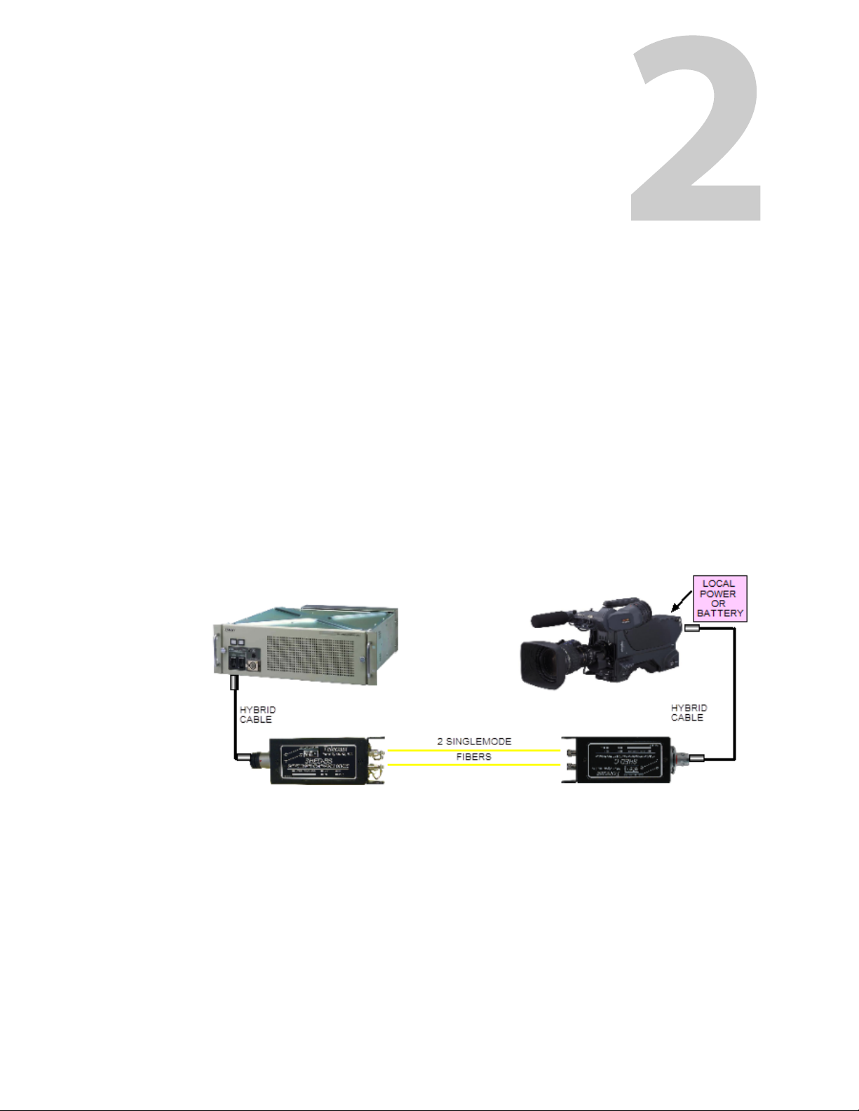
Passive Set-up - SHED-BS and SHED-C
In a Passive set-up, a SHED-BS is connected to a SHED-C with two singlemode fibers
Figure 2-1). In this configuration, the camera head must be locally powered via a battery or
(
a suitable local power supply.
Installation and Configuration
Fig. 2-1: Passive SHED-SHED System
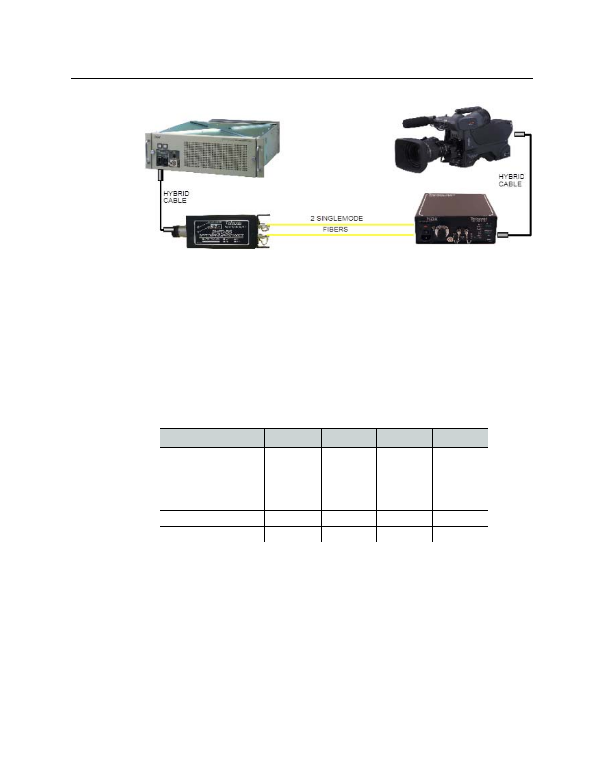
Active Set-up - SHED-BS and HDX
In an Active configuration, a SHED-BS is connected to an HDX via two singlemode fibers
and the HDX supplies power to the camera through up to 100m of SMPTE Hybrid Cable
Figure 2-2).
(
3
Page 8
Installation and Configuration
In each case, a SHED-BS returns an electrical signal to the base station that facilitates the
operation of the camera even though there is no physical copper connection. The SHED-BS
requires no external power supply.
Fig. 2-2: Active SHED-HDX System
SHED-BS Configuration for Camera Types
The SHED-BS supports multiple camera types, and each has different interface
requirements at the CCU end. The SHED-BS must be manually configured for the type of
camera in the system, using four DIP switches on the side of the case. A label is mounted on
the case to show the switch positions for the supported cameras.
Camera Sw 1 Sw 2 Sw 3 Sw 4
Sony ON ON ON OFF
Hitachi HD5000 OFF ON ON OFF
Ikegami ON OFF ON OFF
Panasonic 3500 OFF OFF ON OFF
Panasonic 931B ON ON OFF OFF
Panasonic 3800 OFF ON OFF OFF
SHED-C and PANASONIC 3800 Camera
The Panasonic 3800 camera is a special case - the SHED-C is used to feed power to the
camera. A jack on the SHED-C case accepts 12 VDC, and the 10 VDC required for the camera
is fed down the hybrid fiber cable to the camera.
4
Page 9

Setting Up HDX
The HDX can accept either 120 VAC or 240 VAC. Input voltage selection is NOT automatic; it
must be manually configured by adjusting the Power Entry Module (
The unit accepts AC line voltage with a standard IEC/NEMA type power cord. A window on
the Power Entry Module reflects the current VAC setting, either 115 or 230.
Verify that the voltages on the units are set properly before operating the system.
Changing the Input Voltage
To change the input voltage to the HDX:
1 Use a small, flat-blade screwdriver in the notch at the top of the Power Entry Module to
gently pry open the module cover and expose the fuse block. The cover is hinged at the
bottom and will open easily.
2 Gently pop out the fuse block.
3 Turn the block over and replace it back into the module.
4 Close the module cover.
SHED-C
User Guide
Figure 2-3).
The new input voltage value will be visible in the voltage value window.
The same procedure is followed for fuse replacement. Be careful to replace fuses with ones
of equal voltage, current and duration (3 Amp, 250V, Slo-Blo)
Fig. 2-3: Power Entry Module for HDX
Selecting Normal or Low line voltage range
The HDX operates on AC mains power and can work with a variety of voltages. The internal
power supply can be set for two operating ranges: 120/240 VAC (normal) and 100/200 VAC
(low) +/- 10%, both at 50/60 Hz.
To change between Normal to Low line voltages, it is necessary to open the HDX unit and
change the transformer connections to the Power Entry Module. Proceed as follows:
• Remove all external connections from the HDX.
• Remove the (4) #4-40 screws in the HDX faceplate and carefully withdraw the chassis
from the cover. The connections to the transformer are color-coded and are connected
to the Power Entry Module with 0.187" spade-type connectors ("Fastons"). These are
labeled "A", "B", "C", and "D" on the rear of the power module.
5
Page 10

Installation and Configuration
Selecting Normal or Low line voltage range
IMPORTANT
Be sure to remove all external connections from the HDX including the
power cord before attempting these changes.
To convert from Normal to Low voltage operation:
• Remove the Yellow and Black transformer leads from the Power Entry Module.
• Cover these leads with insulation (electrical tape) to prevent contact with the chassis or
other components.
• Connect the unused Blue and Red leads, below. It is imperative that the leads go to the
correct positions or damage to the HDX may result. Re-assemble the HDX in reverse
order to complete the conversion.
D White White
C Orange Orange
B Blue Yellow
100/200V 120/240V
A Red Black
To convert back to Normal voltage, reverse the above procedure.
6
Page 11

Setting up SHED and SHED-6
The SHED-BS and SHED-C do not require an external electrical power supply of any kind.
The only exception is SHED-C for the Panasonic 3800 camera, which requires an external
power supply. What little power they do consume is provided by the camera system. In a
passive system, only the fiber link of two singlemode ST terminated fibers needs to be
provided. As the camera head is locally powered, the SHED-BS and SHED-C merely serve to
"fool" the camera and base station into believing there is a piece of SMPTE hybrid cable
between them.
SMPTE Hybrid cable lengths should be as short as possible between the CCU and the SHEDBS and between the camera and the SHED-C to maintain optimum performance.
SHEDs can be positioned directly at an access panel (Figure 2-4) or rack mounted with
Grass Valley’s SHED-6, a 1-RU frame that houses six individual SHED-BS units in one simple
enclosure (
Note that the SHED-6 requires 12VDC via a 4-pin XLR-M connector. Please also note that
SHED-6 only supports listed Sony and Ikegami cameras.
• Pin 1: Ground
• Pin 2: Unused
• Pin 3: Unused
• Pin 4: + Power VDC
Figure 2-5).
SHED-C
User Guide
Fig. 2-4: SHED Mounted to Access Panel
Fig. 2-5: SHED-6 Front and Rear Panels
7
Page 12

Installation and Configuration
Fiber Connectors
Fiber Connectors
Your system can be equipped with a variety of different fiber optic connectors, both for the
Hybrid cable and for the two fibers that connect the system together.
Connector options are as shown below.
SHED-BS (Universal Base-Station end, stand-alone)
One End (choose 1) Other End (choose 1)
UFP-304F UFP-2ST
UFP-FIS UFP-2SC
UFP-2STM UFP-2SCA
SHED-C (Universal Camera end, stand-alone)
UFP-2LC
UFP-NOC2
UFP-MX2
One End (choose 1) Other End (choose 1)
UFP-304M UFP-2ST
UFP-FISM UFP-2SC
UFP-2STM UFP-2SCA
UFP-2LC
UFP-NOC2
UFP-MX2
8
Page 13

This chapter presents the features of the SHED and HDX system, including a
Troubleshooting section and a maintenance section.
System Operation . . . . . . . . . . . . . . . . . . . . . . . . . . . . . . . . . . . . . . . . . . . . . . . . . . . . . . . . . . . . . . . . . . . . . 9
HDX . . . . . . . . . . . . . . . . . . . . . . . . . . . . . . . . . . . . . . . . . . . . . . . . . . . . . . . . . . . . . . . . . . . . . . . . . . . . . . . . . . 10
HDX Faceplate Indicators . . . . . . . . . . . . . . . . . . . . . . . . . . . . . . . . . . . . . . . . . . . . . . . . . . . . . . . . . . . . . 10
Compatible Camera Systems . . . . . . . . . . . . . . . . . . . . . . . . . . . . . . . . . . . . . . . . . . . . . . . . . . . . . . . . . 11
SHED-BS . . . . . . . . . . . . . . . . . . . . . . . . . . . . . . . . . . . . . . . . . . . . . . . . . . . . . . . . . . . . . . . . . . . . . . . . . . . . . 13
SHED-C . . . . . . . . . . . . . . . . . . . . . . . . . . . . . . . . . . . . . . . . . . . . . . . . . . . . . . . . . . . . . . . . . . . . . . . . . . . . . . 15
Troubleshooting . . . . . . . . . . . . . . . . . . . . . . . . . . . . . . . . . . . . . . . . . . . . . . . . . . . . . . . . . . . . . . . . . . . . . 16
A Note About Fiber Maintenance . . . . . . . . . . . . . . . . . . . . . . . . . . . . . . . . . . . . . . . . . . . . . . . . . . . . . 17
Block Diagram . . . . . . . . . . . . . . . . . . . . . . . . . . . . . . . . . . . . . . . . . . . . . . . . . . . . . . . . . . . . . . . . . . . . . . . 17
System Operation
Since the HDX does the job of actually powering the camera head, the majority of its
purpose is to produce the high voltages required by today's HD camera and large zoom
lens systems. The remaining purpose is to sense the type of camera system that is attached,
and then proceed through the proper start-up sequence that safely provides the
appropriate voltages.
SHED and HDX Features
Since the optical portions of SHED and HDX systems are passive, the maximum distances
that can be achieved are determined by the optics in your camera system. As most HD
camera systems on the market today have optical budgets of around 12-14db, it is
reasonable to assume that with ideal fiber and minimal connector losses, theoretical
distances of 20km can be realized. Single mode fiber is mandatory.
Once powered up, an HDX with multiple-camera support will attempt to recognize what it
is attached to. The HDX product line is designed to work with:
• Sony 750 and 950 HD Camera systems
• Ikegami HD Camera systems
• Power Plus (see CopperHead manual for details)
• Grass Valley LDK-6000 and -8000 series
• Panasonic 931B, 3500 and 3800
• Hitachi HD1000 andHD5000
See Compatible Camera Systems on page 11 for a complete list of supported camera
systems.
Use of the HDX with any other equipment will result with an error condition indicated by
ERR on the HDX 4-segment display. As long as an error condition is detected, no high
voltage will be enabled.
9
Page 14

SHED and HDX Features
HDX
HDX
HDX Faceplate Indicators
Fig. 3-1: HDX Front Panel Displays
HDX LED Indicators
DC HV
AC IN
Nothing attached Green Unlit Unlit Unlit Red Unlit Unlit
PowerPlus Green Green Unlit Green Unlit Unlit Unlit
Ikegami Green Unlit Green Green Unlit Unlit Unlit
Sony 750 Green Unlit Green Green Unlit Unlit Unlit
Sony 950 Green Unlit Green Green Unlit Unlit Unlit
Panasonic 3500 Green Unlit Green Green Unlit Unlit Unlit
Panasonic 931B Green Unlit Green Green Unlit Unlit Unlit
Panasonic 3800 Green Green Unlit Green Unlit Unlit Unlit
Hitachi Green Unlit Green Green Unlit Unlit Unlit
Grass Valley Green Green Unlit Green Unlit Unlit Unlit
Enable
AC HV
Enable
HV
Present
Cable
Open
Cable
Short
Remote
Pwr Enable
In both active and passive systems, the camera CCU needs to be powered on first and the
camera head needs to be in the ON position. In passive systems, once local power is applied
to the camera, the system should work normally. In active systems, the HDX will take a few
seconds to:
• determine what kind of equipment is attached
• safely apply the correct voltage for that equipment
10
Page 15

LED indicators (see Figure 3-1 and the HDX LED Indicators table above) will show
diagnostic information. An Open or Shorted hybrid cable will always result in a fault
condition. The remainder of the LEDs will be Green or Out depending on what type of
camera (or Power Plus) is attached to the HDX (see the HDX LED Indicators table above).
Incoming optical power is indicated on the lower 4-segment display on the HDX. -20 dBm is
the least amount of optical power that can reliably keep the system functioning. If the CCU
is operating normally (typical optical output of approx. -7 dBm) and the HDX is showing
high loss, check your installed cable for bend radius and connector problems.
The Optional LOCAL/REMOTE switch provides the convenience of having your camera
powered down when optical power to the HDX is turned off. So when the switch is in the
REMOTE position (Faceplate LED = Green), turning your camera CCU Off will also turn
power to the camera head Off.
Compatible Camera Systems
Manufacturer Supported Models
Sony HDC700/750
Ikegami HDK-79E & 790E
Grass Valley LDK-6000 series - all
SHED-C
User Guide
HDC900/930/950
HDC1000/1450/1500/1550
HDC3300
HDCU3300
HDFX-100
BVP-950/CA950 w/CCU900
BVP-9500WS
HDK-725 & 725P
HDK-75EX
HDK-79EX-II & 790EX-II
HDK-79EC & 79EX
HDK-79EXNA
LDK-8000 series - all
Accessory List
Panasonic AK-HC3800
Hitachi CH-HD1000
CH-HD5000
CU-HD500
• Power Supply for SHED-6 (ADAP-AC-02)
•Singlemode patch cords
• Remote Shut-off option for HDX
11
Page 16

SHED and HDX Features
HDX Rack Mount Frame
HDX Rack Mount Frame
The HDX Rack Mount Frame (2 RU) holds two HDXs in a standard rack.
Individual HDXs must be removed from their sheet-metal cases in order to be installed into
an HDX Frame.
• Remove the four Philips-head screws on the top edge of the faceplate
• Slide the HDX chassis out of its case
• Slide the HDX chassis into one side the frame, and secure it using the four screws
removed in the first step.
Note that all connections to the HDX are located on the front panel, so there are no
connections on the rear of the frame.
Fig. 3-2: HDX Rack Mount Frame
12
Page 17

SHED-BS
Description
SHED-C
User Guide
The new SHED-BS is a universal model that can be configured manually, using four
switches, to support the following cameras:
•SONY
•HITACHI
• IKEGAGMI
• PANASONIC 931B
• PANASONIC 3500
• PANASONIC 3800
The four DIP switches, and a label showing the switch positions for the various supported
cameras, are located on the side of the SHED-BS case, as shown in the figure.
• PANASONIC 3800
The camera selection switches, along with a label showing switch positions for the various
supported cameras, are located on the case as shown in the figure.
The DIP switch positions for the cameras, as shown on the label, are as follows:
Camera Sw 1 Sw 2 Sw 3 Sw 4
Sony ON ON ON OFF
Hitachi HD5000 OFF ON ON OFF
Ikegami ON OFF ON OFF
Panasonic 3500 OFF OFF ON OFF
Panasonic 931B ON ON OFF OFF
Panasonic 3800 OFF ON OFF OFF
13
Page 18

SHED and HDX Features
Connectors
Connectors
The SHED-BS is equipped with ST connectors on the fiber-run side, and a LEMO connector
on the CCU side, as shown in the figure. Note that other connectors are available as an
option - see
Fig. 3-3: Shed-BS fiber-run side - ST connectors SHED-BS CCU side - LEMO connector
Fiber Connectors on page 8.
Deployment
A typical deployment of the SHED-BS and HDX to interface a remotely-powered camera to
its CCU is shown in the diagram.
Fig. 3-4: SHED-BS and HDX Deployment Diagram
14
Page 19

SHED-C
Application
Connectors
SHED-C
User Guide
The SHED-C is used in applications where power is applied to the camera locally. The SHEDC can operate in two modes:
•Active - used only with the PANASONIC 3800 camera - power is applied to the camera
from the SHED-C, via a 12VDC external supply connected to the jack on the SHED-C
case. The SHED-C generates the 10 VDC required by the camera, and sends it to the
camera through an SMPTE Hybrid Fiber cable that can be up to 1.5 Km long.
• Passive - used with all other cameras - a local power supply is connected directly to the
camera. The camera is connected to the SHED-C via an SMPTE Hybrid Fiber cable. A
load is placed on the power feed wire used in the active mode.
In both cases, the CCU-end of the fiber run uses a SHED-BS as the Fiber/CCU interface.
The SHED-C is equipped with ST connectors on the fiber-run side, and a LEMO connector
on the camera side, as shown in the figure. Note that other connectors are available as an
option - see
Fiber Connectors on page 8.
Fig. 3-5: SHED-C fiber-run side - ST connectors SHED-C camera side - LEMO connector
The power jack for the 12 VDC supply for active-mode operation with a PANASONIC 3800
camera is located on the side of the case, as shown in the figure.
Fig. 3-6: SHED-C showing the 12 VDC input jack location
15
Page 20

SHED and HDX Features
Deployment
Deployment
The figure shows a typical deployment of a SHED-C and SHED-BS. In this case, the SHED-C is
in passive mode, as a local power supply is connected directly to the camera.
Troubleshooting
Fig. 3-7: SHED-C and SHED-BS Deployment Diagram
Symptom Possible Cause Corrective Action
No AC IN indication Power source Verify correct VAC selector
setting
Be sure power switch is On:
1 = On; 0 = Off
Check fuses
Camera will not power.
RED LEDs for Cable Short
or Cable Open
No Optical Link. Optical
Power Meter reads
>20bDm
HV not being applied (No
HV LED = GREEN)
Bad SMPTE Hybrid cable Check for electrical problems
with hybrid cable and/or
replace the hybrid cable that
connects the CCU to the SHEDBS or the CAMERA to the the
HDX/SHED-C
Bad fiber link • Verify CCU/CAM is on and
optics are working
• Check all fiber to ensure that
connectors are clean and that
there are no bend-radius
issues along the run. Minimize
in-line connectors and
patches, if possible.
Camera system not
powered. Improper
camera system
Make sure that the camera
system is supported
Make sure that the camera
system is powered
16
CAM stays powered ON
when CCU is powered off
Switch in wrong position
at HDX
If you wish the camera to power
down when the CCU is turned
(only if this option is installed)
Page 21

A Note About Fiber Maintenance
As with any fiber optics system, connector cleanliness is one of the most important factors
leading to a successful implementation. The ST connectors on the various components are
very easy to clean with a "Kim-wipe" and 100% pure isopropyl alcohol. There are a number
of other cleaning methods available.
In terms of cleaning the hybrid connector, there are only two acceptable methods. The first
involves having the proper alcohol swab that can be inserted into the optical cavity without
harming the ceramic alignment sleeve. These are one-time use. The other involves removal
of the alignment sleeve via a special tool made by LEMO and others and then using
conventional cleaning methods once the termini is exposed.
Having a routine maintenance/cleaning schedule for all of your fiber optic gear will provide
you with many years of reliable service.
Block Diagram
SHED-C
User Guide
Fig. 3-8: SHED and HDX Functional Block Diagram
17
Page 22

SHED and HDX Features
A Note About Fiber Maintenance
18
Page 23

Specifications
Specifications - SHED-BS & SHED-C
Environment
Dimensions (L x W x H) .................................................................................. 7.5" x 1.9" x 2.5"
Weight ........................................................................................................................................ 1 lb.
Temperature Range ........................................................................................... -20 C to +55 C
Humidity Range ...........................................................................0 to 95% non-condensing
Connectors
HYBRID (SMPTE)................................................................. LEMO (SMPTE 304M) standard,
Optional: Fisher, or 2 STs with 5-pin Molex
Optical ............................................................. Two STs, SCs, SCAs, LCs, OpticalCon or MX
Power Consumption
Base Station unit (SHED-BS)................................................................... Less than 20 Watts
Camera unit (SHED-C).............................................................................. Less than 20 Watts
Transmission
Transmission Method..................................................As determined by camera system
Fiber Types ...............................................................................................................Single-Mode
Wavelength (from/to cam)............................................................................. 1300/1550 nm
Representative Fiber Specifications
Fiber Type ........................................................................................Single Mode (SM) 9/125μ
Attenuation Factor..............................................................................0.5 dB/km @ 1300 nm
Specifications - SHED-6 Frame
Environment
Dimensions (L x W x H) ................................................................................... 17.5" x 1.9" x 7"
Weight ........................................................................................................................................ 2 lb.
Temperature Range ........................................................................................... -20 C to +55 C
Humidity Range ...........................................................................0 to 95% non-condensing
Power Consumption
SHED-6........................................................................................................... Less than 20 Watts
All other Specifications remain the same as for SHED-BS and SHED-C.
Specifications - HDX
Environment
Dimensions (D x W x H) .................................................................................. 13" x 8.4" x 3.4"
19
Page 24

Specifications
Weight ...................................................................................................................................8.5 lbs.
Temperature Range ........................................................................................... -20 C to +55 C
Humidity Range ...........................................................................0 to 95% non-condensing
Connectors
HYBRID (SMPTE) ...................................................................LEMO (SMPTE 304M) or Fisher
Optical ....................................................................................................... Two STs, SCs or SCAs
Input Voltage
Mains........................................................100/120/240 VAC, Nominal, 47 - 63 Hz, 250 VA
Power Consumption
HDX & camera....... 150 VA (120 VA available for camera ops, viewfinder, lens, etc.)
Indicators
LEDs: .............................................................................AC IN, DC HV Enable, AC HV Enable,
HV Present, Cable Open, Short Cable, Remote Pwr Enable
4-Segment Display: ......................................................."Load Type" and "Optical Power"
Transmission
Transmission Method.................................................As determined by Camera System
Fiber Types ...............................................................................................................Single-Mode
Link Margin/Distance........................................................................................... 12 dB/20 km
Wavelength (from/to cam)............................................................................. 1300/1550 nm
Representative Fiber Specifications
Fiber Type ........................................................................................Single Mode (SM) 9/125μ
Attenuation Factor..............................................................................0.5 dB/km @ 1300 nm
Specifications - HDX - Double Frame
Environment
Dimensions (D x W x H) ................................................................................12” x 16.7" x 3.5"
Weight ...................................................................................................................................4.5 lbs.
Temperature Range ........................................................................................... -20 C to +55 C
Humidity Range ...........................................................................0 to 95% non-condensing
All other Specifications remain the same as for individual HDXs.
20
Page 25

Grass Valley Technical Support
For technical assistance, please contact the Grass Valley Technical Support center nearest
you:
Contact Us
Americas
Office hours: 9:00 a.m. – 9:00 p.m. (EST)
Telephone: 1-800-547-8949
+1 530 478 4148
Fax: +1 514 335 1614
support@grassvalley.com
Europe, Middle East, Africa, UK
Office hours: 9:00 a.m. – 6:00 p.m. (GMT)
Telephone: +44 118 952 3444
Fax: +44 118 952 3401
eurotech@grassvalley.com
Playout Automation - Europe,
Middle East, Africa, UK
Office hours: 9:00 a.m. – 5:30 p.m. (GMT)
Telephone: +44 870 500 4350
Fax: +44 870 500 4333
automationsupport@grassvalley.com
France
Office hours: 9:00 a.m. – 5:00 p.m. (GMT+1)
Telephone: +33 1 55 86 87 88
Fax: +33 1 55 86 00 29
eurotech@grassvalley.com
Asia
Office hours: 9:30 a.m. – 6:00 p.m. (GMT+8)
Telephone: +852 2539 6987
Fax: +852 2539 0804
asiatech@grassvalley.com
China
Office hours: 9:30 a.m. – 6:00 p.m. (GMT+8)
Telephone: +86 10 5873 1814
asiatech@grassvalley.com
Malaysia
Telephone: +60 3 2247 1808
asiatech@grassvalley.com
EMERGENCY After Hours (Global)
Toll Free: 1-800-547-8949 (US and Canada)
Telephone: +1 514 333 1772
+1 530 478 4148
Corporate Head Office
Grass Valley
3499 Douglas-B.-Floreani
St-Laurent, Quebec H4S 2C6
Canada
Telephone: +1 514 333 1772
Fax: +1 514 333 9828
www.grassvalley.com
21
 Loading...