

Page 1

SHDSDA1 OPERATION
System HD Eight Output HD-SDI Distribution
Amplifier Operation Manual
SHDSDA1 Version 1 Issue 3 030402 1
CONTENTS
INTRODUCTION TO THIS OPERATION
MANUAL................................................................2
SCOPE OF THIS OPERATION MANUAL.............3
MODULE DESCRIPTION .................................3
FEATURES............................................................4
TECHNICAL PROFILE..........................................5
INPUT................................................................5
OUTPUTS.........................................................5
INDICATOR LEDS............................................5
Standard.......................................................5
Enhanced.....................................................5
ROLLCALL.....................................................5
OPTIONS..........................................................5
REAR INTERFACE CONNECTIONS....................7
REAR INTERFACE NOTATION GUIDE...........7
STANDARD INPUT...........................................7
STANDARD OUTPUTS ....................................7
ROLLCALL MENU SYSTEM.................................8
ROLLCALL MONITORING FEATURES ...............9
Page 2
SHDSDA1 OPERATION
SHDSDA1 Version 1 Issue 3 030402 2
Introduction to this Operation Manual
This manual covers the operation and use of the module described below.
WARNING…
THE FRONT PANEL OF THE UNIT MUST NOT BE
OPENED BY THE OPERATOR. ACCESS IS ONLY
PERMITTED TO FULLY QUALIFIED
INSTALLATION ENGINEERS.
System HD Modules must only be installed and/or replaced by qualified service personnel, with reference to
the System HD Installation guide. Refer all installation and servicing to qualified personnel only.
Manufacturers Notice
Copyright protection claimed includes all forms and matters of copyrightable material and information now
allowed by statutory or judicial law or hereinafter granted, including without limitation, material generated from
the software programs which are displayed on the screen such as icons, screen display looks etc.
Reproduction or disassembly of embedded computer programs or algorithms is prohibited.
No part of this publication may be transmitted or reproduced in any form or by any means, electronic or
mechanical, including photocopy, recording or any information storage and retrieval system, without permission
being granted, in writing, by the publishers or their authorised agents.
Important Notice
No responsibility is taken by the manufacturer or supplier for any non-compliance to EMC standards due to
incorrect installation.
Information in this manual and software are subject to change without notice and does not represent a
commitment on the part of Snell & Wilcox Ltd. The software described in this manual is furnished under a
licence agreement and may not be reproduced or copied in any manner without prior agreement with Snell &
Wilcox Ltd. or their authorised agents.
Page 3
SHDSDA1 OPERATION
SHDSDA1 Version 1 Issue 3 030402 3
Scope of this Operation Manual
This is the operation manual for the System HD Single Channel Distribution Amplifier Module. It covers the
modules ordered under the following codes :
SHDSDA1S-S1 – Standard 8 output distribution amplifier with basic reporting.
SHDSDA1E-S1 – 8 output distribution amplifier with enhanced reporting
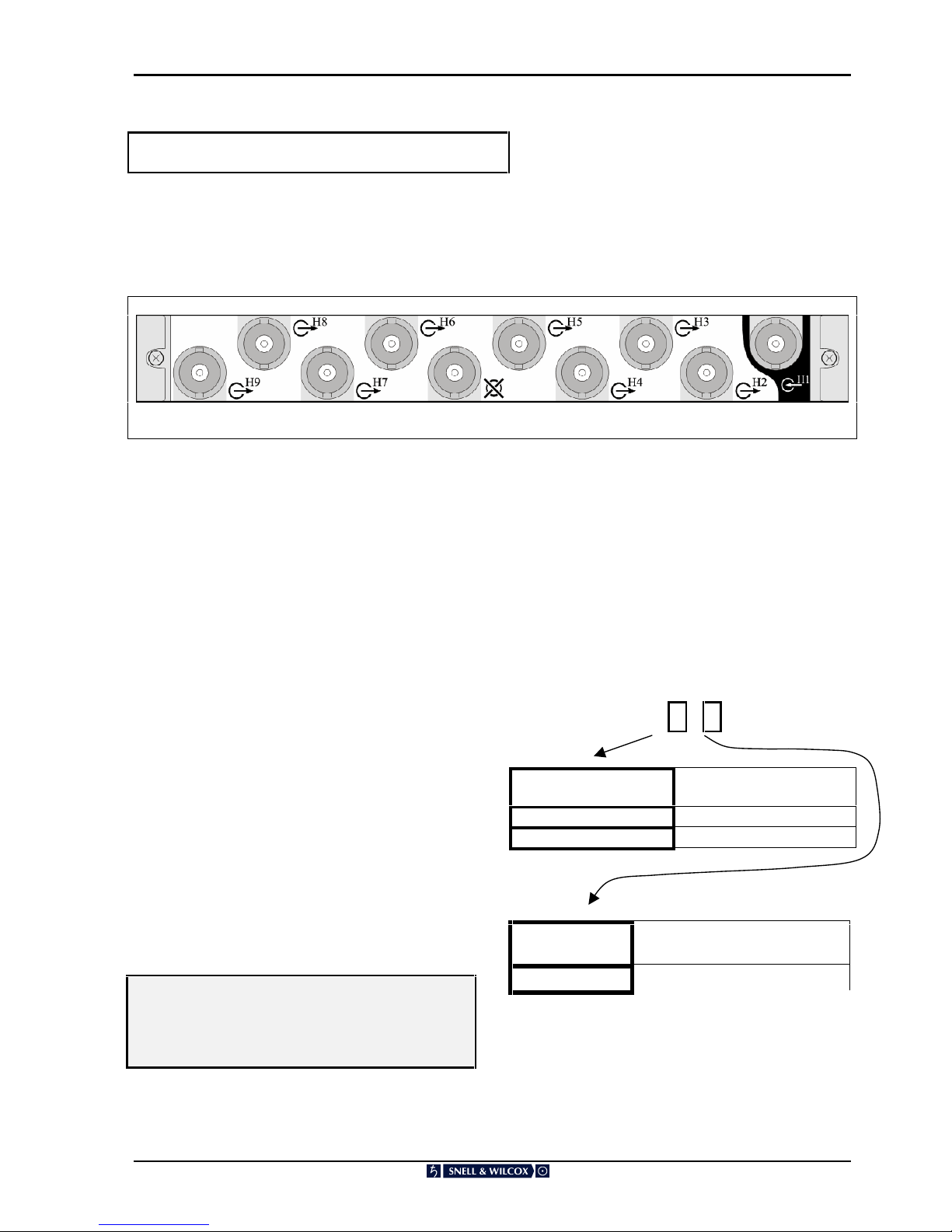
SHDSDA1S-S1 and SHDSDA1E-S1 Distribution Amplifier, Rear Panel View
Module Description
The Eight Output HD-SDI Distribution Amplifier
provides eight reclocked HD-SDI outputs from a
single HD-SDI input.
The electrical high definition serial digital (HD-SDI)
bitstream is input into the distribution amplifier main
board via a 75Ω BNC connector on a rear panel
interface card. The HD-SDI input signal is then
equalised and re-clocked before being split to
provide eight identical coaxial HD-SDI outputs for
the user via 75Ω BNC connectors on the backpanel
of the interface card.
Detailed performance information can be obtained
via the RollCall interface.
Two levels of monitoring sophistication are
available to the user. A standard operational level
is available on all boards, covering parameters
ranging from voltage supply status to the presence
of an input signal. The optional enhanced
monitoring level provides a comprehensive
analysis of the incoming HD-SDI signal such as
CRC error detection, line standard and frame rate
identification.
WARNING…
THE FRONT PANEL OF THE UNIT MUST NOT
BE OPENED BY THE OPERATOR. ACCESS IS
ONLY PERMITTED TO FULLY QUALIFIED
INSTALLATION ENGINEERS.
It is recommended that a record is made of the
System HD Order Code for the module in the table
on the following page. This will allow easy
identification of the monitoring level of the main
board when referring to this manual at a later date.
Quick guide to order codes:
SHD SDA1 X S X
Dist. Amplifier
Code
Properties
S
Standard reporting
E
Enhanced reporting
Interface card
option code
Interface card supplied with
main amplifier board
1
10 BNC labelled for 8 output
Codes other than those listed refer to custom
options.
Amplifier
Interface
card
Page 4

SHDSDA1 OPERATION
SHDSDA1 Version 1 Issue 3 030402 4
Features
n SMPTE292M 1.485Gbit/s HD-SDI data rate
supported
n Eight equalised and reclocked HD-SDI data
outputs
n Can equalise over 100m of cable
n Alarm functions for poor quality input signals
and device malfunction
n Stand-alone or RollCall operation
n Incoming signal analysis available as an
option, it includes:
CRC status
Line standard
Frame Rate
Error rate
Note:
RollCallTM enabled for remote system control &
monitoring.
Page 5

SHDSDA1 OPERATION
SHDSDA1 Version 1 Issue 3 030402 5
Technical Profile
INPUT
Electrical 1.485GBit/s HD-SDI
Connector Format BNC 75ohm panel jack
Input Cable Length 100m
Peak-to-peak
signal amplitude
800mV ± 10%
D.C. offset
0V ± 0.5V
Rise time (20-80%)
Fall time (20-80%)
Difference
< 270ps
< 270ps
≤100ps
Return loss >15dB
OUTPUTS
Electrical 1.485Gbit/s HD-SDI
Connector Format
BNC 75ohm panel jack
Outputs 8
Peak-to-peak
signal amplitude
800mV ± 10%
D.C. offset
0V ± 0.5V
Rise time (20-80%)
Fall time (20-80%)
Difference
< 270ps
< 270ps
≤100ps
Return loss >15dB
INDICATOR LEDS
Not available to the Operator
Standard
Power Power supplies valid
Fault Board fault
Enhanced Monitoring Option
CPU Valid CPU activity
PLL Lock Output locked to input
standard
CRC Error Data error
Line Indicates line standard
Frame Indicates frame rate
Prog/Int Indicates progressive or
interlaced frames
RollCall™
‘Standard’ RollCall
monitoring options:
General alarm
Supply voltage levels
Board temperature
‘Enhanced’ RollCall
monitoring options:
CRC status
Line standard
Frame rate
Error rate
POWER CODE
1
WEIGHT
<750gm (Main Board plus
Interface Board)
OPTIONS
See page 2
Page 6

SHDSDA1 OPERATION
SHDSDA1 Version 1 Issue 3 030402 6
Notes…
1. The eight output HD-SDI distribution
amplifier (DA) is available with two levels of
monitoring sophistication. A standard
option which provides board level
information such as supply faults and
minimum incoming signal analysis. The
enhanced monitoring option adds a
comprehensive incoming signal analysis
capability, including the detection of CRC
errors and identification of the line
standard/frame rate of the signal being
distributed. Refer to the monitor option code
on page 2 to identify what monitoring level
is fitted to the DA board.
2. The interface card for the single channel
eight output DA contains ten BNC
connectors (see following page for
drawing) of which only nine are actually
required for full operation (one IN, eight
OUT), the middle BNC not being used. A
dual channel version of the DA card is also
available (order number SHD_SDA2x S2)
which contains two separate four output
amplifiers. A dual channel DA also has a 10
BNC rear interface card (two lots of 1 IN,
four OUT). The only difference between the
rear interface cards for the two types of DA
is in the backpanel labelling. Mechanically
these two different types of rear interface
card are completely compatible with each
other and can be interchanged between the
different types of DA board. Refer to the
interface card option code on page 2 to
identify what interface card has been
supplied with the eight output DA main
board.
CAUTION: Confusion could arise if
single/double channel rear interface cards are
assigned to the wrong type of DA board.
Though full functionality will be maintained for
both types of DA, the difference in labelling
could be misleading if all such occurrences are
not fully documented at a system level.
Page 7

SHDSDA1 OPERATION
SHDSDA1 Version 1 Issue 3 030402 7
Rear Interface Connections
Rear Interface Notation Guide
Electrical HD-SDI Input
A High Definition Serial Digital electrical input
though a 75Ω BNC connector is denoted in the way
shown opposite. The “ H ” denotes the High
Definition element and the “ n ” is the connection
number for that particular rear interface.
Electrical HD-SDI Output
A High Definition Serial Digital electrical output
though a 75Ω BNC connector is denoted in the way
shown opposite. The “ H ” denotes the High
Definition element and the “ n ” is the connection
number for that particular rear interface.
Standard Input
Electrical HD-SDI
Used On : SHDSDA1S-S1
SHDSDA1E-S1
The high definition serial digital electrical input is
connected to a 75Ω BNC connector. The connector
is shown opposite and is labelled H1 on the rear
panel.
Standard Outputs
Electrical HD-SDI
Used On : SHDSDA1S-S1
SHDSDA1E-S1
The high definition serial digital electrical output is
available from eight 75Ω BNC connectors, each
providing identical outputs. These connectors are
shown below and are labelled H2, H3, H4 H5, H6,
H7, H8 and H9.
Note…
The connector at the middle of the backpanel is not
used with this main board but could be used if a
dual channel main board is inserted (see Technical
Profile, OPTIONS).
Page 8

SHDSDA1 OPERATION
SHDSDA1 Version 1 Issue 3 030402 8
Rollcall Menu System
When a System HD Control and Monitor board is
fitted in the enclosure a range of monitoring
information is available via RollCall
External Monitoring Description
General alarm Input power fault or
overcurrent trip or
system failure
Supply voltage levels Actual voltage levels
Board temperature Actual board
temperature
CRC Status
Line Standard
Frame Rate
Bit error rate Error rate over defined
time period
Page 9

SHDSDA1 OPERATION
SHDSDA1 Version 1 Issue 3 030402 9
Rollcall Monitoring Features
n Module Infrastructure:
General Alarm
Supply Voltage Levels
Board Temperature
n Incoming Signal analysis:
Input Status
Line Standard
Frame Type
Frame Rate
n CRC Error analysis:
CRC Error Count
CRC Error Total
CRC Reset
n Bias/EQ – The value in this field is a guide to
the strength of equalisation that is being
applied to the input signal for longer cable
runs. The lower the value, the less equalisation
is being employed. It is intended as a guide for
troubleshooting the system. It should be noted
that when an equalisation of 100% is shown, it
doesn’t necessarily mean that the maximum
input cable length has been reached. As soon
as CRC errors are being reported then the
input cable length should be decreased until an
error free signal can be received.
Page 10

SHDSDA1 OPERATION
SHDSDA1 Version 1 Issue 3 030402 10
Manual Revision Record
Date Version No. Issue No. Change Comments
16/06/01 1 1 First draft document Issued
051001 1 2 Edited current feature list Only
states features that are present in
current release A1.0.000
New issue released
030402 1 3 New monitoring features added New issue released
 Loading...