

Page 1

Installation and Operations Manual
TM
Page 2

TM
Table of Contents
This manual covers the entire SCRIPT Viewer system, which consists of SCRIPTedit, SCRIPTview, miniVIEWER, and integration with
PVTV STUDIO. If you are using SCRIPTedit as a stand-alone product, or you are not using SCRIPT Viewer with the PVTV STUDIO
system, then you can use this Table of Contents to find the sections that apply to your configuration.
I. Meet Your SCRIPT Viewer
▼ Congratulations on Your Purchase . . . . . . . . . . . . . . . . . . . . . . . . .1
▼ Product Description . . . . . . . . . . . . . . . . . . . . . . . . . . . . . . . . . . . .1
▼ General Information . . . . . . . . . . . . . . . . . . . . . . . . . . . . . . . . . . .2
▼ For Your Safety . . . . . . . . . . . . . . . . . . . . . . . . . . . . . . . . . . . . . . .3
▼ SCRIPT Viewer Components . . . . . . . . . . . . . . . . . . . . . . . . . . . .4-5
II. Install Your SCRIPT Viewer
▼ Rackmount Rear Panel I/O Connections . . . . . . . . . . . . . . . . . . . . .6
▼ Rack-Mounting the CPU . . . . . . . . . . . . . . . . . . . . . . . . . . . . . . . .7
▼ Connection Block Diagrams . . . . . . . . . . . . . . . . . . . . . . . . . . . .8-9
▼ Installing the Flat-Panel Display
• Installing the Anti-glare Hood . . . . . . . . . . . . . . . . . . . . .10
• Mounting the Display . . . . . . . . . . . . . . . . . . . . . . . . . .10
• Attaching the Display . . . . . . . . . . . . . . . . . . . . . . . . . . .11
▼ Connecting the SCRIPT Viewer System
• Connecting the DA to the SCRIPT Viewer CPU . . . . . . . . .12
• Connecting the DA to the SCRIPTview Displays . . . . . . . .12
• Connecting SCRIPT Viewer CPU to the Cameras . . . . . . .13
• Connecting SCRIPT Viewer to PVTV STUDIO . . . . . . . . . .14
• Connecting the Keyboard and Mouse . . . . . . . . . . . . . .15
• Connecting the Monitor . . . . . . . . . . . . . . . . . . . . . . . . .15
▼ Connecting the SCRIPT Viewer Keypad
• Attaching the Keypad . . . . . . . . . . . . . . . . . . . . . . . . . .16
• Changing the Keypad Address . . . . . . . . . . . . . . . . . . . .16
▼ Powering Up . . . . . . . . . . . . . . . . . . . . . . . . . . . . . . . . . . . . . . . .17
III. Use Your SCRIPT Viewer System
▼ Adjusting the Flat-Panel Display’s Image . . . . . . . . . . . . . . . . . . . .18
▼ PVTV SCRIPT Viewer Software . . . . . . . . . . . . . . . . . . . . . . . . . . .19
▼ Introduction to SCRIPTedit
• Opening SCRIPTedit . . . . . . . . . . . . . . . . . . . . . . . . . . . .20
• The SCRIPTedit Window . . . . . . . . . . . . . . . . . . . . . . . . .20
▼ The SCRIPTedit Menus and Toolbars
• File Menu and Toolbar Icons . . . . . . . . . . . . . . . . . . . . .21
• Edit Menu and Toolbar Icons . . . . . . . . . . . . . . . . . . . . .22
• View Menu and Toolbar Icons . . . . . . . . . . . . . . . . . . . .23
• Insert Menu and Toolbar Icons . . . . . . . . . . . . . . . . . . . .24
• Format Menu and Toolbar Icons . . . . . . . . . . . . . . . . . . .25
• Spelling Menu . . . . . . . . . . . . . . . . . . . . . . . . . . . . . . . .26
• Viewer Menu and Toolbar Icons . . . . . . . . . . . . . . . . .27-28
• Script List Menu . . . . . . . . . . . . . . . . . . . . . . . . . . . . . .28
• Help Menu . . . . . . . . . . . . . . . . . . . . . . . . . . . . . . . . . .28
• Other Toolbar Icons . . . . . . . . . . . . . . . . . . . . . . . . . . . .29
▼ The SCRIPT Viewer Keypad . . . . . . . . . . . . . . . . . . . . . . . . . . . . .30
▼ The SCRIPTedit Basics
• Customizing the SCRIPTedit Window . . . . . . . . . . . . . . .31
• Creating a New Script . . . . . . . . . . . . . . . . . . . . . . . . . .32
• Opening and Existing Script . . . . . . . . . . . . . . . . . . . . . .32
• Formatting the Text . . . . . . . . . . . . . . . . . . . . . . . . .33-35
• Saving a Script . . . . . . . . . . . . . . . . . . . . . . . . . . . . . . .36
• Printing a Script . . . . . . . . . . . . . . . . . . . . . . . . . . . .36-37
▼ The SCRIPTview Basics
• Loading a Script into SCRIPTview . . . . . . . . . . . . . . . . . .38
• Activating The miniVIEWER . . . . . . . . . . . . . . . . . . . . . .39
• The miniVIEWER Window . . . . . . . . . . . . . . . . . . . . . . .40
• The SCRIPTview Status Window . . . . . . . . . . . . . . . . . . .40
• The SCRIPTview Toolbar . . . . . . . . . . . . . . . . . . . . . . . . .41
▼ SCRIPTview Commands . . . . . . . . . . . . . . . . . . . . . . . . . . . . . . . .42
▼ Setting SCRIPTview options . . . . . . . . . . . . . . . . . . . . . . . . . . .42-44
▼ Testing PVTV SCRIPT Viewer - STUDIO Functionality . . . . . . . . .45-46
▼ The Keyboard Overlay . . . . . . . . . . . . . . . . . . . . . . . . . . . . . . . . .47
IV. Appendices
▼ Appendix A: Specifications . . . . . . . . . . . . . . . . . . . . . . . . . . . . . .48
▼ Appendix B: Warranty Information . . . . . . . . . . . . . . . . . . . . . . . .49
▼ Appendix C: Closed-Caption Installation & Operations . . . . . . .50-51
▼ Appendix D: Standard AP NewsCenter Installation & Operations52-53
▼ Appendix E: AvStarInstallation & Operations . . . . . . . . . . . . . . .54-55
▼ Appendix F: Advanced AP Installation & Operations . . . . . . . . .56-57
Installation and Operations Manual • © 1999 ParkerVision, Inc.
Page 3

TM
Page 1
Congratulations on Your Purchase
Your PVTV SCRIPT Viewer enables you to create, edit, and playback scripts using a dynamic, interactive teleprompting system.
This manual covers the installation, configuration, and use of your SCRIPT Viewer system.
As part of ParkerVision’s STUDIO Products family, the SCRIPT Viewer is fully compatible with all
PVTV STUDIO Products and can easily fit into existing ParkerVision camera systems. To run and
view scripts, your SCRIPT Viewer provides a flat-panel display designed to move with the
camera. You can control the font size, scroll speed, and display via the keypad or software
interface.
If you have questions on how to install or operate your CameraMan 1-CCD/3-CCD General Pan
Tilt camera, please refer to the installation and operations manuals included with the camera.
You will see three icons in this manual:
This icon alerts you to important instructions in the operation and maintenance of
your PVTV SCRIPT Viewer.
This icon alerts you to tips or noteworthy suggestions in the operation, use, or
maintenance of your PVTV SCRIPT Viewer.
This icon refers you to the 1-CCD or 3-CCD General Pan/Tilt Camera Installation
and Operations Manual that came with your camera.
Product Description
The ParkerVision SCRIPT Viewer is an interactive teleprompting system that enables you to
control the speed and format of the text on the fly. SCRIPT Viewer enables you to create a
script or import a text file using its SCRIPTedit™ software, and then view it using SCRIPTview™.
Variable font sizes and scroll speed can be controlled via the graphical user interface or a
wireless RF keypad.
The system features a fully integrated 12” direct view, flat panel display with full color,
enabling the talent to read the text easily whether sitting still or moving. Each SCRIPT Viewer
system can support multiple display panels without the need for additional software.
© 1999 ParkerVision, Inc. • Meet Your SCRIPT Viewer™
Your PVTV SCRIPT Viewer should include these
components:
• 12" flat panel display w/mounting brackets
• Four #10 screws
• Flat panel power supply
• SCRIPT Viewer Processor Unit with rack mounts
• SCRIPT Viewer keypad w/2AA batteries
• 12" SCRIPT Viewer anti-glare hood
• ParkerVision Keyboard
• ParkerVision 15" monitor
• ParkerVision Serial Mouse
• ParkerVision Mouse Pad
• SCRIPT Viewer 25 ft (7.6 m) RS-485 Cable
• VGA Splitter (4 output) w/ 6 ft (1.8 m) Cable
• 25 ft (7.6 m) VGA Cable
• SCRIPT Viewer Manual
• ParkerVision Software Key
• SCRIPT Viewer Software Kit
Page 4

TM
General Information
Page 2
Installation and Operations Manual • © 1999 ParkerVision, Inc.
Important Identification Numbers
Before you begin assembling and using your PVTV SCRIPT Viewer, please take a moment to
find the Model and Serial number tag on your unit, and fill out the following information:
Microsoft, Windows NT, and/or other Microsoft products referenced herein are either
trademarks or registered trademarks of Microsoft Corporation.
The terms Visibly Better, System II, IMAGE, WhisperDRIVE Plus, autoTRACK, MY TURN, and
General Pan/Tilt Camera System are registered trademarks of ParkerVision, Inc. in the United
States of America. The terms CameraMan, PVTV and ParkerVision are registered logos in the
United States of America. Federal law prohibits any commercial use of these registered
trademarks and logos.
The manufacturer reserves the right to change specifications and warranty at any time without
notice or obligation.
Refer all Warranty and Servicing to the ParkerVision Customer Support Center listed in the back
of the installation and operations manual that came with your CameraMan camera.
No part of this manual may be copied or reproduced without express written consent of
ParkerVision, Inc. © 1999 ParkerVision, Inc.
8493 Baymeadows Way
Jacksonville, FL 32256
800-532-8034
904-737-1367 phone
904-731-0958 fax
support@parkervision.com e-mail
http://www.parkervision.com website
PARKERVISION
™
MODEL # ________________
SERIAL # ________________
TM
2.1
Page 5

TM
Page 3
Important Notices
© 1999 ParkerVision, Inc. • Meet Your SCRIPT Viewer™
Safety Notices
1. Do not use this apparatus near water.
2. Clean only with a damp cloth.
3. Do not defeat the safety purpose of the polarized or grounding-type plug. A polarized
plug has two blades with one wider than the other. A grounding type plug has two
blades and a third grounding prong. The wide blade or the third prong is provided for
your safety. When the provided plug does not fit into your outlet, consult an electrician
for replacement of the obsolete outlet.
4. Unplug this apparatus during lightning storms or when unused for long periods of time.
5. Refer all servicing to qualified service personnel. Servicing is required when the apparatus
has been damaged in any way, such as power supply cord or plug is damaged, liquid has
been spilled or objects have fallen into the apparatus, the apparatus has been exposed to
rain or moisture, does not operate normally, or has been dropped.
Software Notification
PVTV SCRIPT Viewer comes with all the required software and hardware to run successfully.
Do not load any software (including system software, upgrades, etc.) without contacting
ParkerVision Customer Support at 1-904-737-1367.
Installation of any non-ParkerVision software could dramatically affect system operation and
voids the product warranty.
The following section describes important material and instructions regarding the installation and use of ParkerVision equipment.
Please:
• Read these instructions.
• Keep these instructions.
• Heed all warnings.
• Follow all instructions.
FCC Compliance Information
This equipment has been tested and found to comply with the
limits for Class A digital devices, pursuant to Part 15 of the FCC
Rules. These limits are designed to provide reasonable
protection against harmful interference when the equipment is
operated in a commercial environment. This equipment
generates, uses, and can radiate radio frequency energy and, if
not installed and used in accordance with this manual, may
cause harmful interference to radio communications. Operation
of this equipment in a residential area is likely to cause harmful
interference in which case the user will be required to correct
the interference at their own expense.
This unit was tested with shielded cables on the peripheral
devices. Shielded cables must be used with the unit to insure
compliance.
ParkerVision is not responsible for any radio or TV interference
caused by unauthorized modifications to this equipment. Such
modifications could void the user's authority to operate the
equipment.
Page 6
TM
PVTV SCRIPT Viewer Components
The following information introduces you to each of the PVTV SCRIPT Viewer’s components and their features.
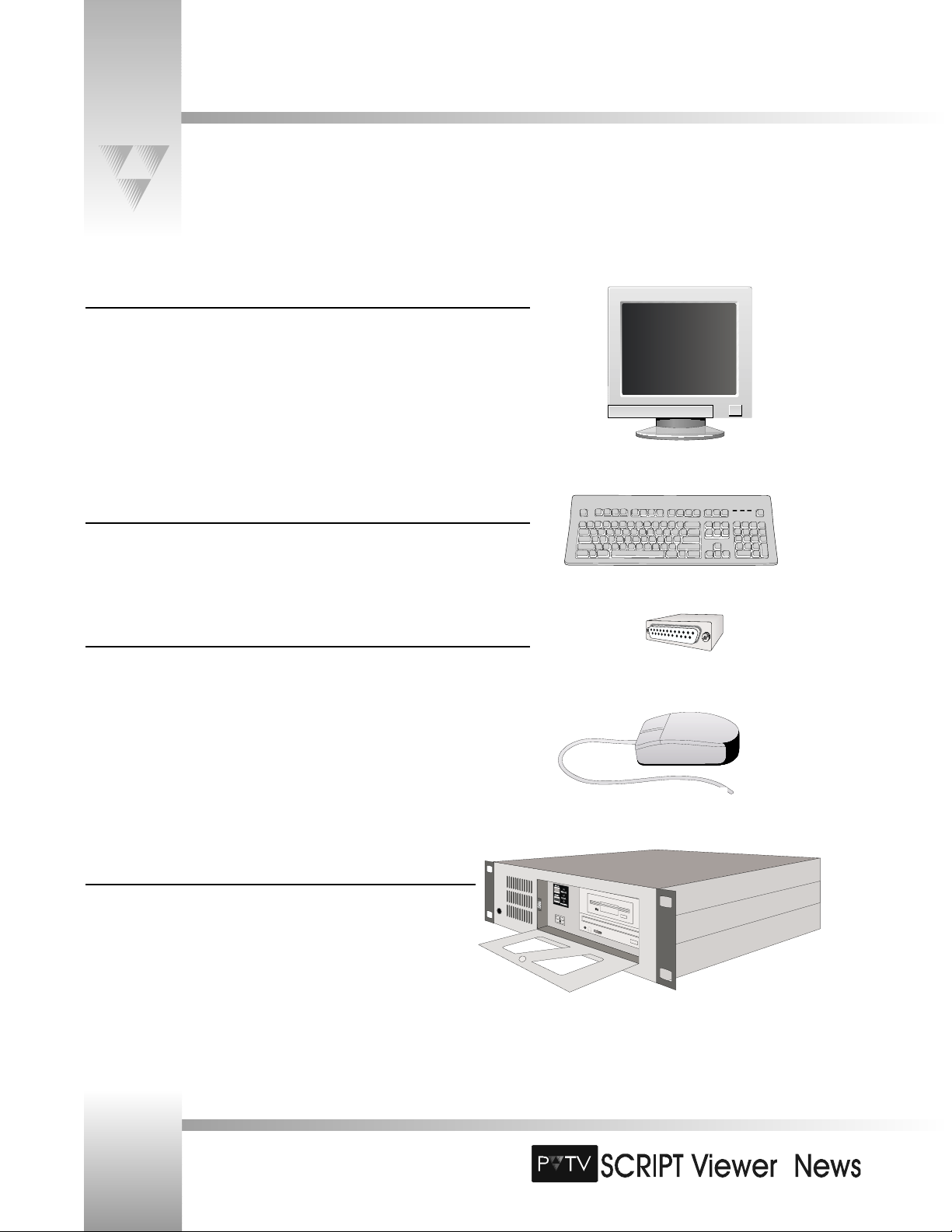
Computer System
SCRIPT Viewer Processor Unit with rack mounts
ParkerVision 15" monitor
ParkerVision Keyboard
SCRIPT Viewer Keypad Template
ParkerVision Serial Mouse
ParkerVision Security Key
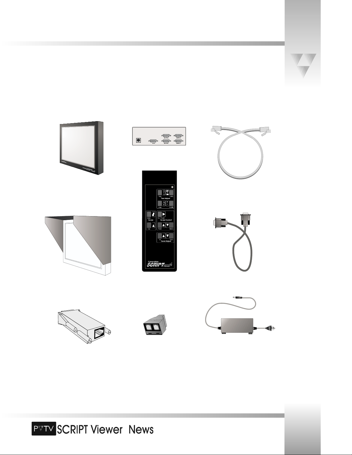
SCRIPT Viewer Display
12" flat panel display w/mounting brackets
Script Viewer anti-glare hood
SCRIPT Viewer Power and Connection Accessories
Flat panel display power supply
SCRIPT Viewer 25 ft (7.6 m) VGA Cable
4-output VGA Distribution Amplifier with 6 ft (1.8 m) Cable
SCRIPT Viewer adapter (RS-485 to DB9)
ParkerVision T-Connector
25 ft (7.6 m) CameraMan Communication Cable
3 ft (.9m) CameraMan Communication Cable
SCRIPT Viewer Included Accessories
SCRIPT Viewer keypad w/2AA batteries
SCRIPT Viewer Literature/Software Pack
ParkerVision Mouse Pad
Page 4
Installation and Operations Manual • © 1999 ParkerVision, Inc.
15” Monitor
Keyboard
Security Key
Mouse
Processing Unit
Page 7
TM
Page 5
PVTV SCRIPT Viewer Components
© 1999 ParkerVision, Inc. • Meet Your SCRIPT Viewer™
CameraMan
Communication Cable
(RS-485)
VGA Distribution Amplifier
Anti-Glare Hood
SCRIPT Viewer adapter
SCRIPT Viewer Display
SCRIPT Viewer Keypad
VGA Cable
Power Supply
T-Connector
Page 8
TM
Page 6
Installation and Operations Manual • © 1999 ParkerVision, Inc.
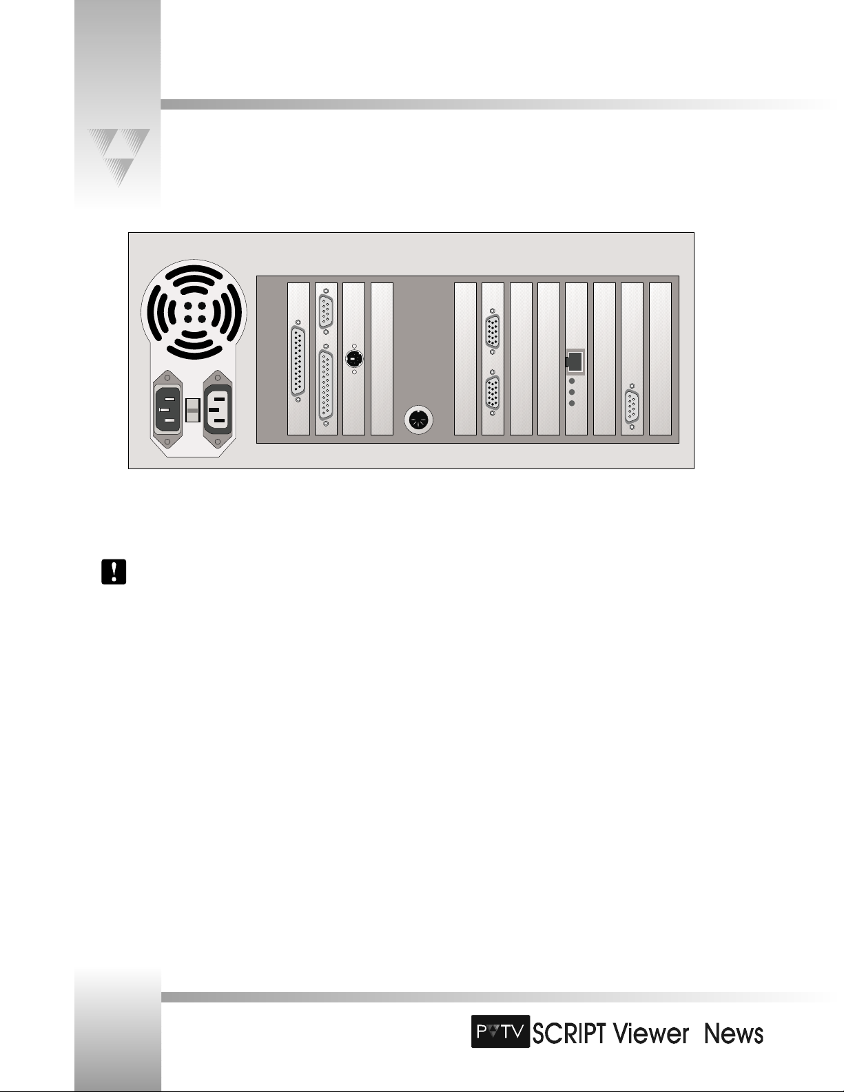
Rackmount Rear Panel I/O Connections
Before you begin connecting your SCRIPT Viewer system, look at the rear panel of your SCRIPT Viewer CPU.
▼
1 AC Power Input - Used to supply power to
the SCRIPT Viewer CPU.
The switch to the right of the AC
power input indicates the input
voltage. The default setting is 115v.
Before using outside of the U.S. or
Canada, check your AC voltage
requirements before using and adjust
the switch if necessary.
▼
2 AC Power Output - Auxiliary AC Power
Supply. Reserved for future use.
▼
3 Software Key Port - 25-pin male connector
used with supplied software key to enable the
SCRIPT Viewer software.
▼
4 COM 1 Port - Reserved for future use.
▼
5 COM 2 Port - Reserved for future use.
▼
6 Mouse Port - Standard PS-2 jack used to
connect the SCRIPT Viewer CPU to the mouse.
▼
7 Keyboard Port - Standard PC/AT keyboard
jack used to connect the SCRIPT Viewer CPU
to the keyboard.
▼
8 Distribution Amplifier (DA) Port - 15 -pin
VGA connector used to connect the SCRIPT
Viewer CPU to the supplied DA.
▼
9 Monitor Port - 15 -pin VGA connector used
to connect the SCRIPT Viewer CPU to the 15”
editing monitor.
▼
10 Network Connection - RJ-11 eight -pin
female port used for communications with
ParkerVision’s PVTV STUDIO.
▼
11 RS-485 Port - DB-9 connection used for serial
communications between the SCRIPT Viewer
CPU and CameraMan camera’s Base Unit or
Main Docking Station.
▼▼
1
▼▼
2
▼▼
3
▼▼
4
▼▼
5
▼▼
6
▼▼
7
▼▼
8
▼▼
9
▼▼
10
▼▼
11
Page 9
TM
Page 7
© 1999 ParkerVision, Inc. • Meet Your SCRIPT Viewer™
Rack-Mounting Your SCRIPT Viewer System
The SCRIPT Viewer CPU contains the hardware and software for creating and editing SCRIPT Viewer files, as well as setting up and
controlling the data displayed on the remote SCRIPT Viewer flat-panel displays. The following pages explain how to mount,
connect, and install your SCRIPT Viewer system.
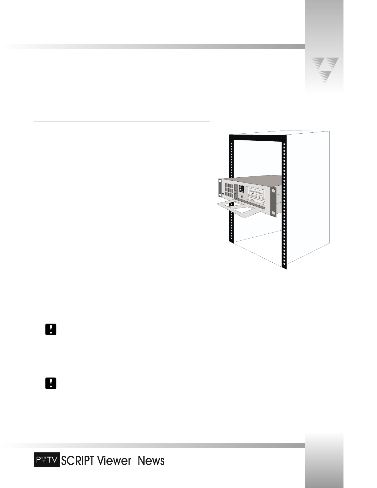
Rack-Mounting the CPU
The CPU is designed to fit into a standard 19” wide equipment rack and requires 7” of vertical
rack space. Check with the rack manufacturer for its exact measurements. The CPU should not
be mounted directly above or below other devices such as amplifiers or uninterruptible power
supplies (UPS) that generate high levels of ambient heat. The SCRIPT Viewer CPU should be
installed only in a location in which the ambient temperature is between 65°F and 75°F (18°C 24°C).
To rack-mount the SCRIPT Viewer CPU into a standard 19” rack or console:
1. Remove all packing materials from the CPU and make note of the connections on the
rear of the box.
2. The SCRIPT Viewer system includes a 25-pin software key required for operating the
SCRIPTview software. This key can be installed prior to mounting the CPU into the
rack. The key should be connected to the mating 25-pin port on the rear of the CPU
and secured using a small flat-blade screwdriver.
3. Holding the CPU firmly by the sides, carefully slide the box into the rack from the
front. Position the box completely into the rack and make sure that the four holes on
each corner align with corresponding holes on the rack brackets. If these holes do
not align, you may have a problem with the rack and it may be necessary to
reposition other devices.
4. Use four standard rack-mount screws (not included) to secure the CPU to the rack.
You also may wish to use Teflon washers under the screw-heads to protect the
finish on the CPU box. Screws and washers of the proper size are typically
available from the rack manufacturer.
5. Loosely tighten one screw at a time, using slight pressure on the front-mounted
handles to lift or lower the box for exact alignment of the holes.
Forcing a screw to turn with the unsupported weight of the CPU box on its
threads can damage the screw and/or the threaded hole.
6. After all four screws have been installed, and the CPU is in place, go back and hand
tighten the screws firmly.
Page 10
TM
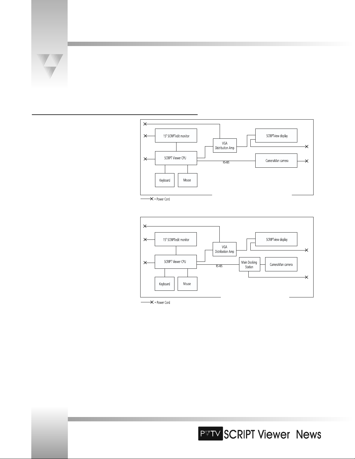
Connection Block Diagrams
The PVTV SCRIPT Viewer accommodates up to four flat-panel displays per Distribution Amplifier (DA). With additional DAs, it can
control as many displays as you need. It also can be configured to work with or without CameraManSTUDIO. The next two pages
illustrate how to connect SCRIPT Viewer in various system configurations.
Connecting to Single-Camera Systems
When connecting SCRIPT Viewer directly to a single
camera, you do not need to use the T-Connector
included with the system. That connector is used when
you connect SCRIPT Viewer to PVTV STUDIO, and
when multiple cameras are daisy-chained.
Page 8
Installation and Operations Manual • © 1999 ParkerVision, Inc.
How to connect SCRIPT Viewer to a single,
non-tracking camera.
How to connect SCRIPT Viewer to a
single, tracking camera.
Page 11
TM
Page 9
Connection Block Diagrams
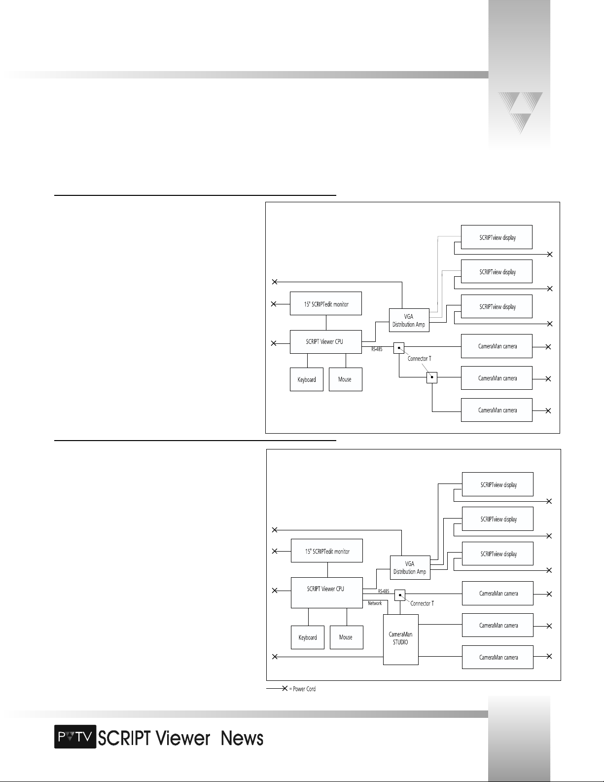
Connecting to Multi-Camera Systems
Connecting SCRIPT Viewer to a multi-camera system is essentially
the same as a single-camera system, except that you must use a
T-Connector to daisy-chain the cameras. This allows each camera to
have communications with the SCRIPT Viewer CPU.
© 1999 ParkerVision, Inc. • Install Your SCRIPT Viewer™
Connecting to PVTV STUDIO
When used with PVTV STUDIO, SCRIPT Viewer can be controlled in
three ways: 1) from the SCRIPTedit interface, 2) from within the
PVTV STUDIO interface, and 3) from a hand-held wireless keypad.
The diagram to the right explains how to connect SCRIPT Viewer to
PVTV STUDIO to facilitate the following control functions:
Network Communications- This one-wire connection facilitates
information sharing between SCRIPT Viewer and PVTV STUDIO.
This enables you to operate SCRIPT Viewer from within the PVTV
STUDIO interface.
RS-485 Communications- This connection enables you to make
adjustments to the script using a wireless keypad. This requires the
use of a T-Connector.
Page 12
TM
Page 10
Installation and Operations Manual • © 1999 ParkerVision, Inc.
Installing the Flat-Panel Display
Before you begin connecting cables, you need to mount the flat-panel displays on the cameras. The displays are designed to fit
securely on the top of each camera, allowing it to pan and tilt with the motion of the camera.
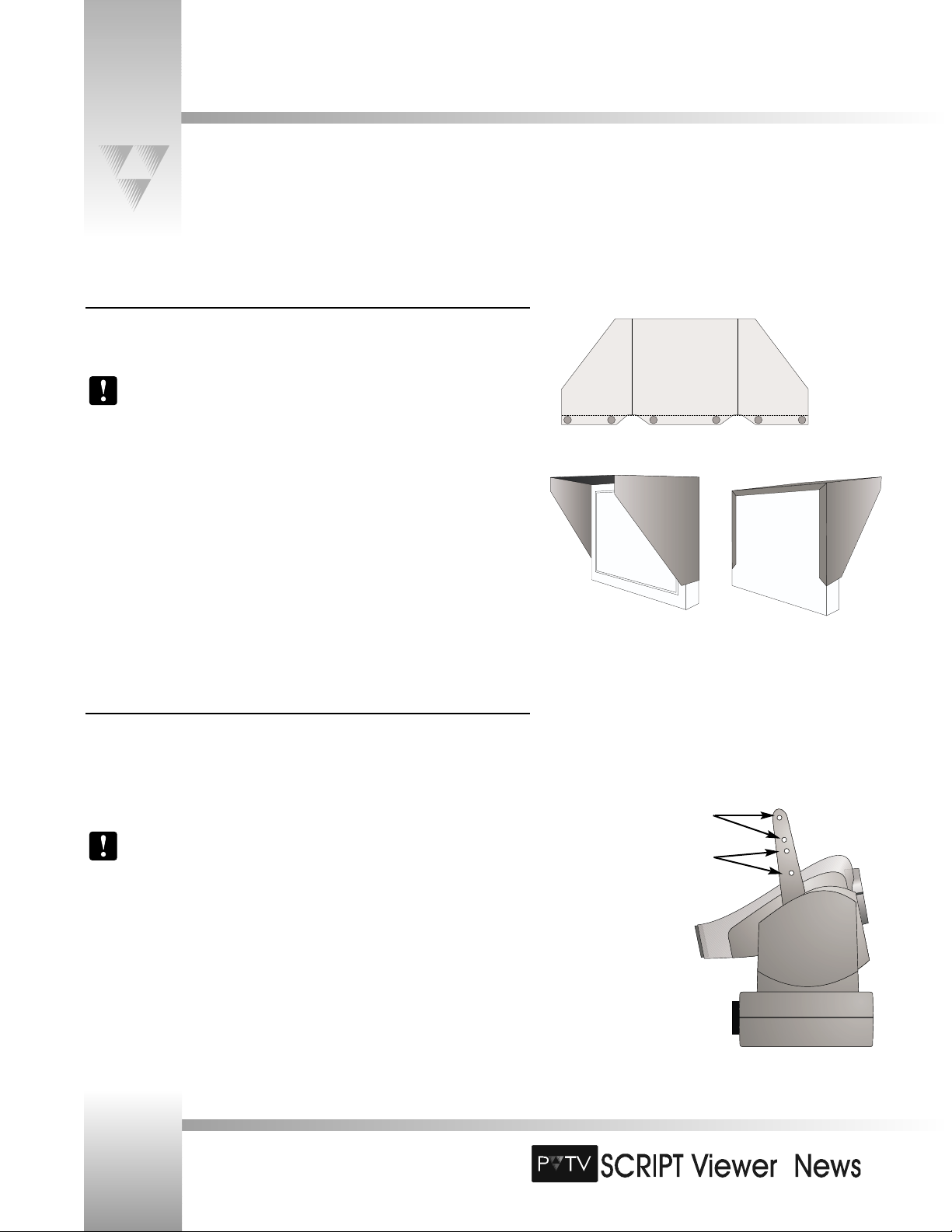
Installing the Anti-Glare Hood
Your SCRIPT Viewer system comes with an Anti-Glare Hood. When properly installed, it
protects the flat-panel display from the glare of studio lights.
The anti-glare hood should be installed onto the flat panel display before the display is
mounted to the camera, to reduce the risk of stress on the camera brackets/gears.
The Anti-Glare hood is delivered as a flat piece of plastic and must be bent at the seams to
attach to your display. There are also 6 velcro attachments that allow the hood to be mounted
on the display. The hood should be installed on the display before attaching the display to the
camera brackets (the bracketrs are factory-installed).
To install the Anti-Glare hood:
1. Bend the flat, plastic hood at the five (5) seams to configure it for your display.
2. Peel the plastic off the velcro attachments leaving the two pieces together.
3. Take your display and gently wrap the hood around it. The velcro attachments
should attach to the back of the panel.
4. Press the velcro attachments firmly in place to secure the hood to the display.
Mounting the Display
The flat-panel display is shipped with mounting brackets attached. These brackets are
designed to mate with display brackets optionally installed on 1-CCD and 3CCD ParkerVision cameras. Ensure that your display(s) and your camera(s) are
fitted with the proper brackets.
CameraMan cameras intended to be used with SCRIPT Viewer displays
are shipped from the factory with display brackets attached. If you are
attaching a display to a previously-purchased camera, you need to send
the camera to ParkerVision to have display brackets installed. See the
contact information on pages 2-3.
The camera’s display brackets contain four
holes on each bracket.
• When installing the display on 3-CCD
cameras, use the top two holes.
• When installing the display on 1-CCD
cameras, use the bottom two holes.
Page 13
TM
Page 11
© 1999 ParkerVision, Inc. • Install Your SCRIPT Viewer™
Installing the Flat-Panel Display
Mounting Brackets
attached to flatpanel display.
Display Brackets
attached to
CameraMan camera
(3-CCD shown).
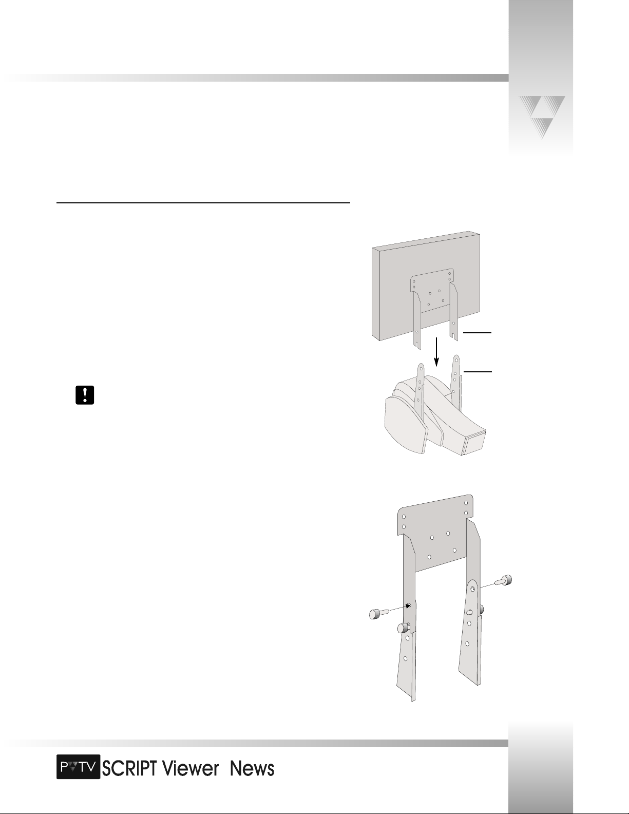
Attaching the Display
To attach the display:
1. Using a CameraMan SHOT Director, or Camera Control Keypad, tilt the camera all the
way UP. This will keep the camera from ratcheting while you are attaching the
display.
2. Using the supplied #10 screws, loosely thread one screw into each display bracket in
the LOWER screw hole corresponding to your camera type (the bottom hole for 1CCD, the second from the top for 3-CCD).
3. Install the flat-panel display by sliding the display’s attached mounting brackets over
the outside of the camera’s display brackets so that the slotted end of the mounting
bracket arms rest on the screws applied in step 2.
Be aware that the camera becomes top-heavy after you install the SCRIPT Viewer
display unit. Severe damage to both the display and the camera can result from
the units tipping over and falling.
4. Without releasing the display, thread one of the remaining #10 screws through the
remaining hole in the mounting bracket and into the display bracket. Screw it in
tightly.
5. Using the same method as step 4, thread the final screw into the remaining hole on
the other bracket. Screw it in tightly.
6. Tighten all screws with a #2 Phillips screwdriver.
Page 14
TM
The VGA Distribution Amplifier (DA) is used by the SCRIPT Viewer system to distribute the SCRIPT Viewer data to the flat-panel
displays. The DA can sit on a flat surface, or can be rack-mounted with the optional rack-mount unit from ParkerVision.
This DA is required to drive the flat-panel displays, even if you are using only a single display.
Page 12
Installation and Operations Manual • © 1999 ParkerVision, Inc.
Connecting the SCRIPT Viewer System
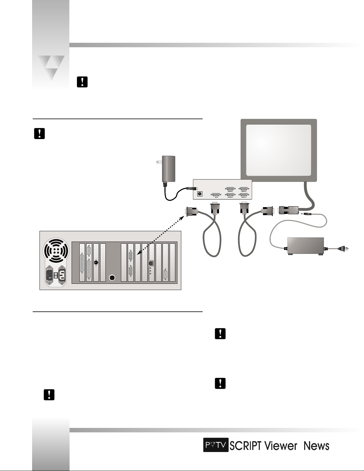
Connecting the DA to the SCRIPT Viewer CPU
The preferred method of installing the DA is in a 19” wide rack. This ensures that
cabling to and from the unit is protected, and any future service is accomplished more
easily.
1. Locate the video connectors on the rear of the DA - they are
marked VIDEO IN (one connector) and VIDEO OUT
(four connectors).
2. Connect one end of the 6’ VGA extension cable (included
with SCRIPT Viewer) to the DA connector port marked VIDEO
IN. Connect the other end to the DA port
on the rear
panel of the CPU.
Connecting the DA to the SCRIPTview Displays
1. Insert the male end of the 25’ VGA cable (included with SCRIPT Viewer) into one of the
VIDEO OUT
ports on the DA, and the female end into the display’s attached
VGA/power cable
. Repeat for each additional display.
2. Connect the flat-panel’s power supply
to the power jack on the display’s attached
VGA/power cable, then plug the cord into a grounded power outlet. Repeat for each
display.
3. Connect the supplied DA power cable
to the DA, and plug it into a power outlet.
Power may be applied to the display at any time. Since the supply always
provides power to the backlight of the display when plugged in, it is best to
unplug the supply from the power jack when not in use.
Make sure all Monitor Type DIP Switches on the front
of the DA are in the UP position. This ensures that the
monitor ID bits are read from the flat-panel display
plugged into the Monitor 1 output port.
At least one flat-panel display must be plugged into the
Monitor 1 output port, regardless of the number of
displays.
Page 15
TM
Page 13
© 1999 ParkerVision, Inc. • Install Your SCRIPT Viewer™
Connecting the SCRIPT Viewer System
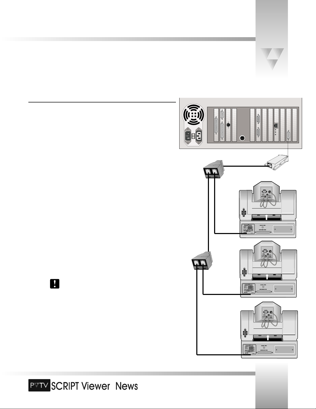
Connecting the SCRIPT Viewer CPU to the Cameras
To get full functionality out of your PVTV SCRIPT Viewer, it is necessary to connect the CPU to
your cameras. This RS-485 connection gives the reader the ability to control the text they see
on the displays with a wireless keypad. With the keypad, the reader can adjust the script’s font
size, scroll speed, and scroll direction. They also can load and cue up new scripts, and play and
pause scripts.
To connect the SCRIPT Viewer CPU to the cameras:
1. Locate the 9-Pin RS-485 Port
on the rear panel of the SCRIPT Viewer CPU.
2. Attach the RS-485 adapter
(included with SCRIPT Viewer) to the port.
For Single-Camera Systems:
3. Connect one end of the 25’ RS-485 communications cable (included with SCRIPT
Viewer) to the RS-485 adapter. Connect the other end of the cable to the RS-485
port on the back of the camera.
For Multi-Camera Systems:
3. Connect one end of the 6’ RS-485 communications cable (included with SCRIPT
Viewer) to the RS-485 adapter. Connect the other end of the cable to the single port
on the included T- Connector
.
4. Connect one end of an RS-485 communications cable (there are two included with
SCRIPT Viewer) to one of the remaining ports on the T-Connector. Attach the other
end of the cable to the RS-485 port on the back of the first camera.
When more than one camera is being used, select the one closest to
where the SCRIPT Viewer keypad will be used. Also, verify that the RF
ENABLE switch on the back of the camera is set to ON. The remaining
cameras should have their RF switch OFF.
5. Connect another RS-485 communications cable between the remaining port on the
T-Connector and the single port on a second T-Connector.
6. Connect one end of the second RS-485 communications cable to one of the
remaining ports on the T-Connector. Attach the other end of the cable to the RS-485
port on the back of the next camera.
Page 16
TM
Page 14
Installation and Operations Manual • © 1999 ParkerVision, Inc.
Connecting the SCRIPT Viewer System
7. Repeat steps 5 and 6 for each additional camera.
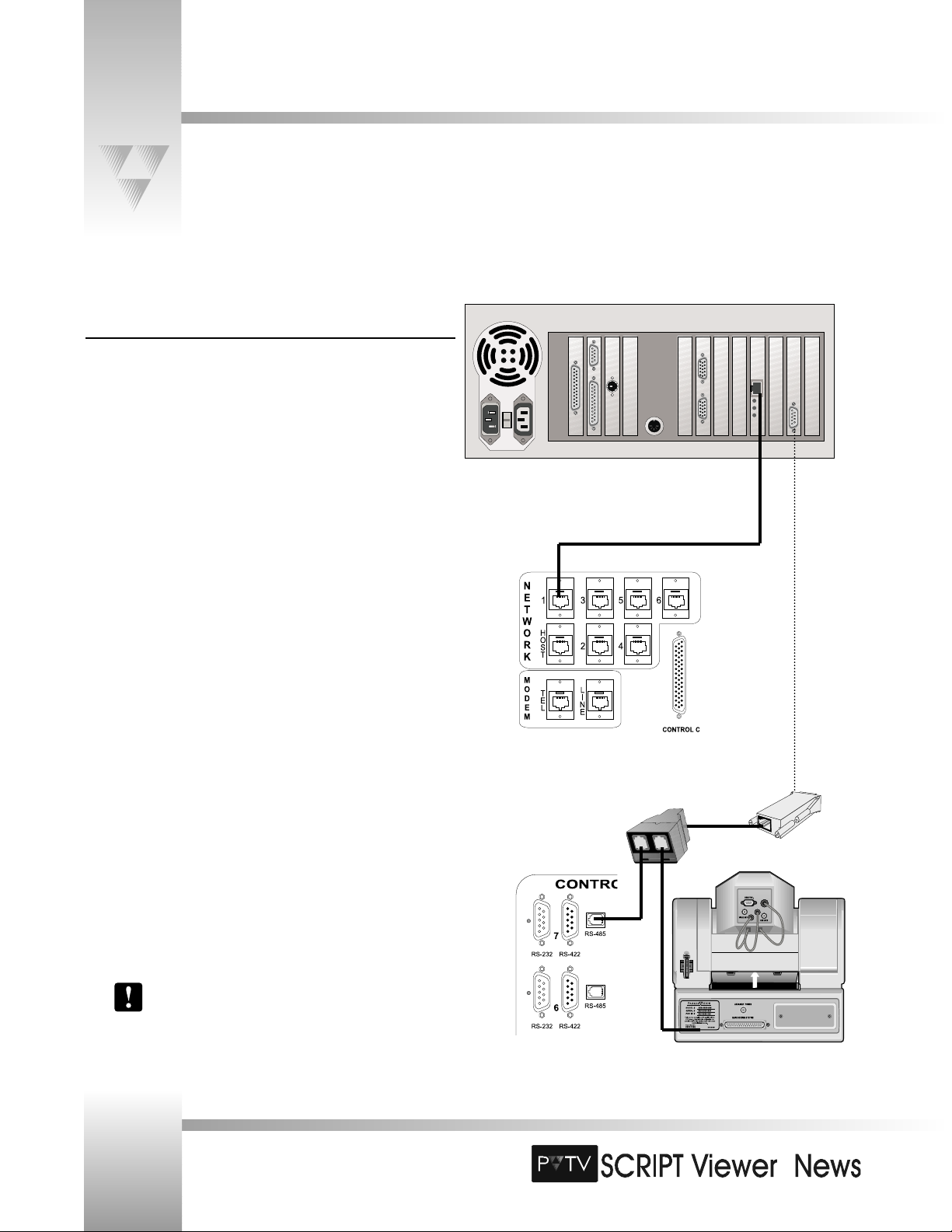
Connecting SCRIPT Viewer to PVTV STUDIO
To control SCRIPT Viewer from within PVTV STUDIO Interface:
1. Locate the Network Communication port
on the rear panel of
the SCRIPT Viewer CPU.
2. Connect one end of the RJ-11 8-pin cable (included with SCRIPT
Viewer) to the Network Communications port.
3. Connect the other end to the NETWORK 1 port
on the rear
panel of the PVTV STUDIO CPU.
To control SCRIPTview displays with wireless keypad:
1. Locate the 9-pin RS-485 port
on the rear panel of the SCRIPT
Viewer CPU.
2. Attach the RS-485 adapter (included with SCRIPT Viewer) to the port.
3. Connect one end of the 6’ RS-485 communications cable (included
with SCRIPT Viewer) to the RS-485 adapter. Connect the other end to
the single port on the included T- Connector.
4. Connect one end of an RS-485 communications cable (there are two
included with SCRIPT Viewer) to one of the remaining ports on the
T-Connector. Attach the other end to one of the RS-485 control ports
on the rear panel of the Serial Control module.
5. Connect another RS-485 communications cable between the
remaining port on the T-Connector and the RS-485 port on the
camera.
6. For each additional camera in your network, use another RS-485
communications cable to connect it to one of the other RS-485
control ports on the Serial Control module.
Please refer to your PVTV STUDIO manuals for further
installation instructions.
Page 17
TM
Page 15
Connecting the SCRIPT Viewer System
© 1999 ParkerVision, Inc. • Install Your SCRIPT Viewer™
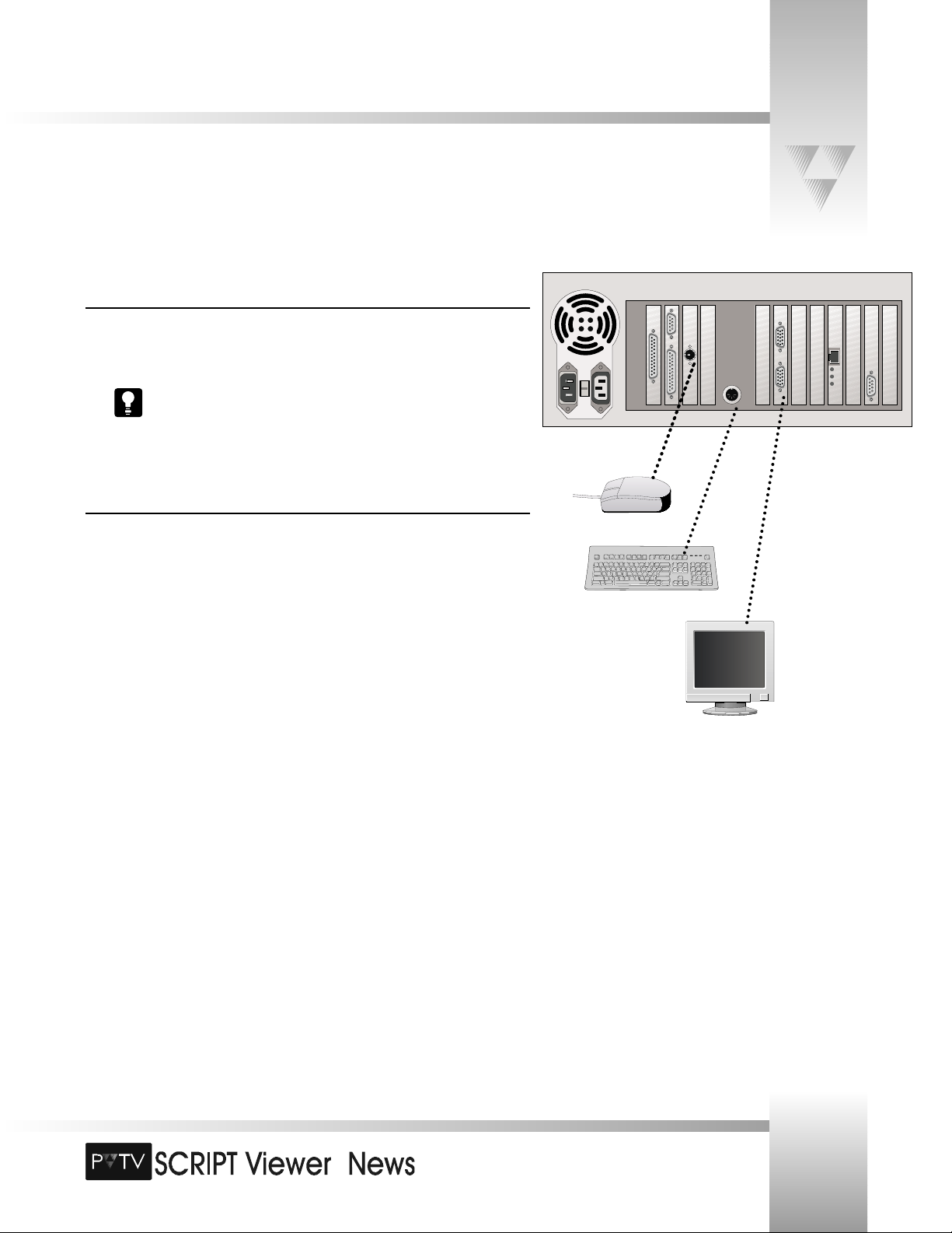
Connecting the Keyboard and Mouse
1. Insert the mouse cable into Connector
on the CPU back panel.
2. Insert the keyboard cable into Connector
on the CPU back panel.
You can control a script with a SCRIPT Viewer keypad or with the computer
keyboard. The keypad can control the SCRIPT Viewer through RF or it can be
attached to the camera (see page 16).
Connecting the Monitor
1. If not already attached, insert the power cables into the monitor’s power inlet. Plug the
other end into a grounded power outlet.
2. Attach the VGA cable to the Video (VGA) Connector
on the CPU back panel. Insert
the other end into the VGA Input on the back of the monitor.
Page 18
TM
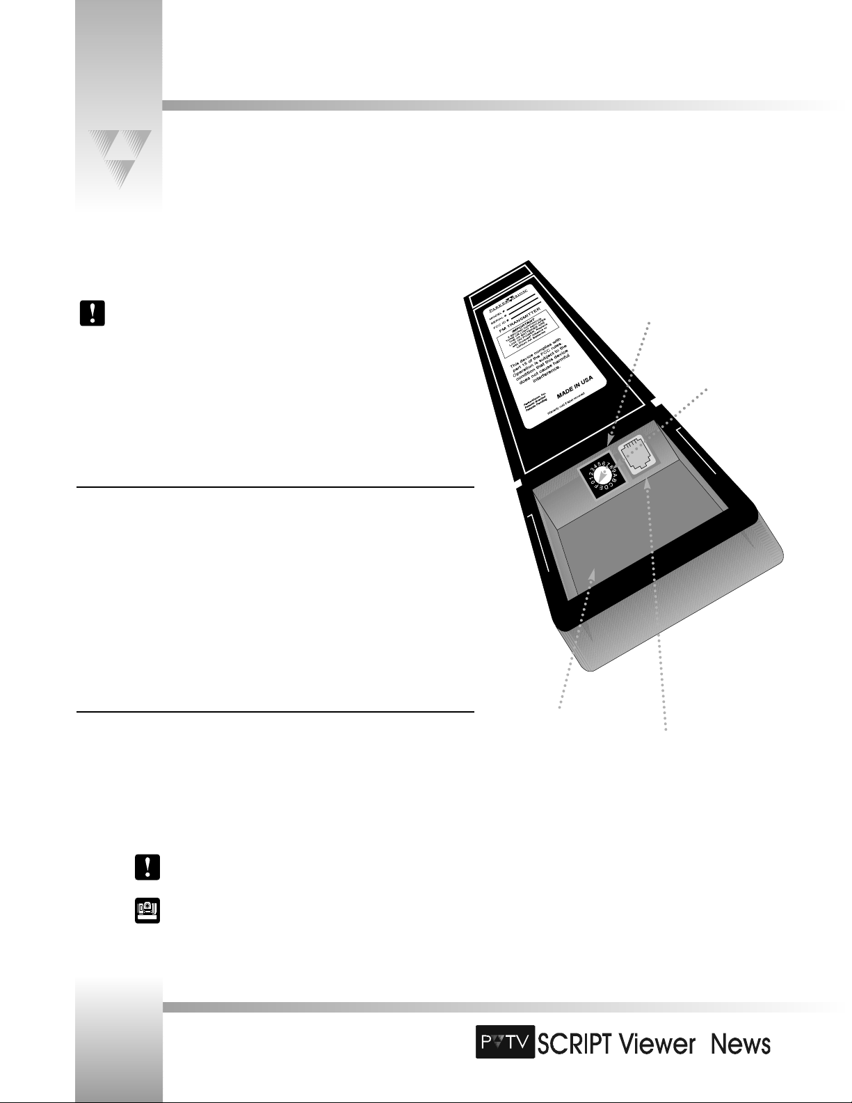
Connecting the SCRIPT Viewer Keypad
Your PVTV SCRIPT Viewer comes with a Keypad that can be operated in either wireless RF or hard-wired mode. You will need to
set the base address to use the keypad with SCRIPT Viewer.
Page 16
Installation and Operations Manual • © 1999 ParkerVision, Inc.
The remote keypad included with your SCRIPT Viewer system operates via RF (Radio
Frequency), and is coded to communicate reliably with ParkerVision cameras. Under
normal operating conditions this keypad should not be affected by outside
interference. However, if you operate one or more additional SCRIPT Viewer systems
within 2000’ (610 m) of one another, it will be necessary for ParkerVision Support to
modify one or more of your SCRIPT Viewer systems to enable all remote keypads to
operate without interfering with one another. See pages 2-3 for ParkerVision Support
information.
Attaching the Keypad
You can control a script with a SCRIPT Viewer keypad or through the computer keyboard and
mouse. The keypad can control the SCRIPT Viewer through RF or it can be hardwired to the
camera. When your camera is shipped to you, there is a 6-pin, 25’ PVI cable included. This
cable can be used to hardwire either the Tracking System Keypad (TSK), the Camera Control
Keypad (CCK) or the Script Viewer Keypad (SVK).
1. To hardwire the keypad to the camera, insert the keypad cable into the PVI COM port on
the back of your ParkerVision camera.
2. If using the keypad in the wireless mode, two (2) AA batteries are required.
Verifying The Keypad Address
The SCRIPTviewer keypad and CPU adrresses are preset at the factory. You should never have
to change this address.
Verify that the keypad address is set to F and that no other cameras in the network are set to
this address.
For multiple-camera applications, refer to page 9.
For information on how to set the Base Unit Address on your
CameraMan camera, refer to the 1-CCD or 3-CCD CameraMan’s
installation and operations manual.
RJ-11 jack, for hardwired mode
Battery compartment
Keypad Address
Address at F
Page 19

TM
Now that you’ve connected all the components, you are ready to power up the system and begin configuring and using the
software.
Page 17
© 1999 ParkerVision, Inc. • Install Your SCRIPT Viewer™
Powering Up
Powering Up Your System
To power up the SCRIPT Viewer system:
1. Turn on the 15” SCRIPTedit monitor.
2. Turn on the SCRIPT Viewer CPU (the on/off switch is located behind the keyed door
on the front panel of the CPU
).
3. The SCRIPTview flat-panel displays turn on when you power up the SCRIPT Viewer
CPU.
Split Screen Processing
PVTV SCRIPT Viewer software splits the screen in half with the SCRIPTedit application
automatically loading on the 15” monitor and the SCRIPTview application running on
all the flat-panel displays.
Other installed software, like Windows NT®, will view the monitors and displays as
one screen, so dialog boxes and splash screens) may appear off center. However, they
are appearing half on the 15” monitor and half on the displays.
What to Expect at Startup
At startup, you will see the Windows NT boot-up procedures and splash screen. Then you will
be asked to do two things initially to log on:
1. When prompted, press CTRL, ALT, and DELETE simultaneously.
2. When prompted for a password, press ENTER.
You can add or change the password at any time, see the Microsoft Windows
NT manual for instructions on how to do this.
Starting the Software
When you initially power up (boot up) SCRIPT Viewer, SCRIPTview will appear on the flat panel
display. If it does not load, you will need to start it.
To start SCRIPT Viewer:
1. Go to the Windows Start menu.
2. Select Programs.
3. Select Startup.
4. Click SCRIPTview.
15” Monitor
Flat-panel Display
Double-click the SCRIPT Viewer Icon
from the Window’s Desktop.
-OR-
Page 20

TM
Page 18
Installation and Operations Manual • © 1999 ParkerVision, Inc.
Adjusting the Flat-Panel Display’s Image
At this point, the SCRIPTedit software should be loaded and in view on the 15” monitor. The SCRIPTview software should be
loaded on each flat-panel display. The following information enables you to adjust the image that appears on the flat-panel display.
Each display should be adjusted as needed.
Display Switches
The image switches on the 12” display are located just below the mounting bracket.
This switch controls the contrast of the display. Usually the highest contrast is
most desirable.
This switch selects the direction for the other four switches.
This switch is used to position the image horizontally within the bezel of the
monitor.
This switch is used to position the image vertically within the bezel of the
monitor.
This switch is used to provide horizontal frequency adjustment in the image,
and controls the image width.
Brightness
The brightness of the display can be set to one of two positions. The switch at the lower-left
corner of the housing allows the brightness to be shifted between either high brightness or
low brightness modes. Remember that the tilt of the monitor will have an effect on the
contrast.
Cleaning
The display can be cleaned with general-purpose window cleaner and a soft cloth. Spray the
cloth instead of the display when applying the cleaner. DO NOT use industrial solvents.
Brightness Switch
Page 21

TM
© 1999 ParkerVision, Inc. • Use Your SCRIPT Viewer™ System
Page 19
PVTV SCRIPT Viewer Software
The SCRIPT Viewer system runs on the Windows NT platform and consists of a dual GUI interface divided into SCRIPTedit and
SCRIPTview. SCRIPTedit is viewed on the local (editing) monitor, while SCRIPTview is viewed on the flat-panel display. To help you
find your way through the software, you need to familiarize yourself with the menus and toolbars of the SCRIPT Viewer system.
This section introduces you to the GUI interface for both SCRIPTedit and SCRIPTview.
SCRIPTedit SCRIPTview
Page 22

TM
Introduction to SCRIPTedit
Page 20
Installation and Operations Manual • © 1999 ParkerVision, Inc.
Opening SCRIPTedit
SCRIPTedit should load automatically when your system boots up. If it does not, follow the
steps below:
1. Click Start on the Windows task bar.
2. Select Programs.
3. Move the cursor to Startup.
4. Select SCRIPTedit from the submenu.
If you open a script from the Viewer/File menu into SCRIPTview with SCRIPTedit
open, then you are prompted to load that script into the SCRIPTedit window.
The name of the file is shown on the title bar at the top of the SCRIPTedit window.
The SCRIPTedit Window
SCRIPTedit, ParkerVision’s dynamic editing software, enables you to create, edit, and run scripts
of any length, at multiple speeds, and in a variety of colors.
The SCRIPTedit window is divided into three main segments:
• Menu Bar: Used to open, save, format and configure scripts.
• Toolbars: Used to quickly format scripts, open files, and control the scrolling text.
• Text Editing Area: Used to import, write, and edit scripts.
Page 23

TM
Page 21
The SCRIPTedit Menus and Toolbars
File Menu and Toolbar Icons
The following commands execute various functions in SCRIPTedit. Select any of the following
options from the SCRIPTedit File menu:
New: Opens a blank editing window for you to create a new Script.
Open: Opens an existing Script using the Open dialog box.
Save: Saves an open Script using the same file name. Follow the prompts to save any
changes and load the Script into SCRIPTview.
Append: Adds the open Script to the end of the Script currently displayed in
SCRIPTview.
•
Save As: Saves an open Script to a specified file name. Use the Save As dialog box to
specify the location and Script name.
• Script Information: Opens the SCRIPTedit Script Statistics dialog box, where you can
document the title and subject of your script and change the script’s run time.
Print: Prints a Script to the printer. Use the Print dialog box to set specifications
before printing.
Print Preview: Displays the Script on the screen as it would appear printed. Use the
Preview window to view, zoom, or print the Script.
• Page Setup: Provides a Page Setup dialog box to set paper, margin, and orientation
settings.
• Most Recent Scripts: Lists the three most recent scripts edited in SCRIPTedit.
• Send: Allows user to send open script to an email recipient..
• Exit: Exits SCRIPTedit.
© 1999 ParkerVision, Inc. • Use Your SCRIPT Viewer™ System
The SCRIPTedit menus available in SCRIPTedit enable you to control the functionality of the SCRIPTedit software and the
appearance of the screen. The toolbar icon is indicated next to the function, if applicable.
Page 24

TM
The SCRIPTedit Menus and Toolbars
Edit Menu and Toolbar Icons
Use the following shortcuts to help edit a Script. Select any of the following options from the
Edit menu:
Undo: Reverses the last action.
Cut: Cuts the selected text and copies it to the clipboard.
Copy: Copies the selected text to the clipboard.
Paste: Pastes the last Cut or Copied text at the cursor’s insertion point.
• Clear: Clears the selected text.
• Select all: Selects the entire Script.
Find: Use the Find function to search for specific words or characters.
• Find Next: Use the Find Next function to search for the next appearance of a selected
word or character.
• Replace: Use the Replace function to search and replace words or characters.
Page 22
Installation and Operations Manual • © 1999 ParkerVision, Inc.
Page 25

TM
Page 23
The SCRIPTedit Menus and Toolbars
View Menu and Toolbar Icons
You can use the View menu or the Options dialog box accessed from the View menu to
display or hide the SCRIPTedit toolbars described below. Click View, then select a toolbar from
the menu items. A checkmark indicates which toolbars are active.
• Show Toolbar:
When selected, displays toolbar with basic commands, such as creating, opening, or saving a Script file.
• Show Format Bar:
When selected, displays toolbar that provides list boxes for font type and size, and includes the format buttons shown above.
• Show Status Bar:
When selected, displays information about the SCRIPT Viewer at the bottom of the SCRIPTedit window, it also indicates when
NUM and CAP locks are active.
• Show Script Control Bar:
When selected, displays a toolbar allowing you to cue, pause, and play the scrolling script.
• Clip Mouse Cursor: When selected, confines the movement of the SCRIPT Viewer cursor to editor window only.
While ON-AIR, you should clip the cursor to avoid accidentally moving the cursor over to the SCRIPTview monitor.
© 1999 ParkerVision, Inc. • Use Your SCRIPT Viewer™ System
Page 26

TM
The SCRIPTedit Menus and Toolbars
Insert Menu and Toolbar Icons
Use this menu to insert information or commands into the script that tell the SCRIPT Viewer to
perform a given action. Select any of the following options from the Insert menu:
Cue Command: Opens the Insert Cue Command dialog box, where you can enter a
startup delay time for the script - this will pause the script for a given length of time
before beginning to scroll.
Delay Command: Opens the Insert
Delay Command dialog box, where
you can insert a delay time anywhere in
the script - this will pause the script for
a given length of time.
Pause Command: Inserts a pause in the script - this will stop the script until you
manually restart it.
TMacro Step: Opens the Insert Tmacro Step Command dialog box. Sends a
command to PVTV STUDIO to continue the Transition Macro if it is stopped at a
step mark. If the Transition Macro is not stopped at a step mark, then the command
is ignored.
Date and Time: Opens the Date and Time dialog box so you can insert the date and
time in the script in a given format.
• File: Inserts the contents of a given .RTF or .TXT file at the current cursor location.
Page 24
Installation and Operations Manual • © 1999 ParkerVision, Inc.
Page 27

TM
Page 25
The SCRIPTedit Menus and Toolbars
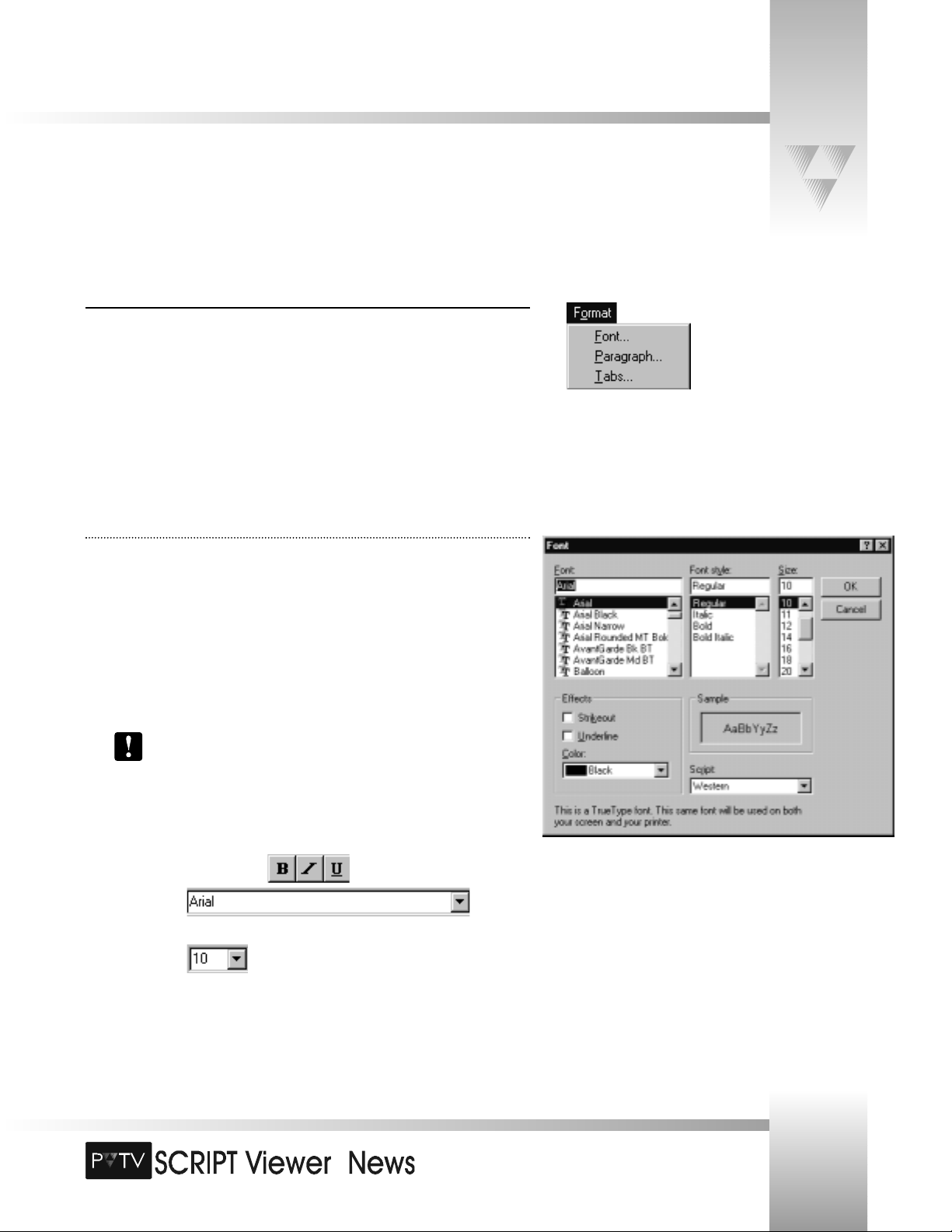
Format Menu and Toolbar Icons
Use the Format menu to change formatting, margins, alignment, or tab settings. Select any of
the following options from the Format menu:
Font: Displays the Font dialog box, where you can adjust the text’s typeface, font style, size,
and color.
Paragraph: Displays the Paragraph dialog box, where you can adjust the margins and text
alignment (left, center, and right justification).
Tabs: Displays the Tabs dialog box, where you can adjust the location of each paragraph tab
in your script.
© 1999 ParkerVision, Inc. • Use Your SCRIPT Viewer™ System
Page 28
TM
The SCRIPTedit Menus and Toolbars
For information on the operation of SCRIPT Viewer’s spell-checking software, refer to the HighSpell online help option
(located at the bottom of the Spelling menu).
Page 26
Installation and Operations Manual • © 1999 ParkerVision, Inc.
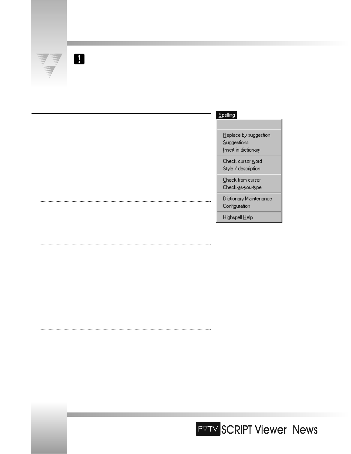
Spelling Menu
PVTV SCRIPT Viewer comes with a built-in spell-checker and thesaurus called HighSpell. The Spelling
menu provides access to the primary spell-checking functions in HighSpell.
• Open Space: Displays the word currently being checked by HighSpell.
• Replace By Suggestion: If an immediate suggestion was made during typing, click this menu item
to replace the erroneous word with the suggested word.
• Suggestions: Opens the suggestions dialog box, where you’ll see HighSpell’s suggested
replacement words for the given erroneous word.
• Insert in Dictionary: Inserts the erroneous word in the designated dictionary file.
• Check Cursor Word: When selected, HighSpell checks the word at the cursor. All active correction
options and automatic hyphenation are applied. If the word is hyphenated already, it is linked
together. If the word is not found or cannot be corrected, a status message is displayed.
• Style/Description: Opens the Word Description and Synonyms dialog box.
• Check From Cursor: Runs the range-checking function, which tests an entire script, or a highlighted
text area.
• Check-As-You-Type: Turns on or off the check-as-you-type feature, which checks every word as you
type it and beeps if there is a typing error.
• Dictionary Maintenance: Opens the HighSpell Dictionary Maintenance dialog box, where you
can edit the HighSpell dictionary.
• Configuration: Opens the HighSpell Options dialog box, where you can configure HighSpell’s
text-checking behavior.
• HighSpell Help: Launches the HighSpell help file.
Page 29

TM
Page 27
The SCRIPTedit Menus and Toolbars
Viewer Menus and Toolbars
PVTV SCRIPT Viewer consists of two software applications that work together:
SCRIPTedit and SCRIPTview. The Viewer menu enables you to cue, pause, and make
changes to the text scrolling in the SCRIPTview window.
If you are working only in SCRIPTedit, and SCRIPTview is not running, then the
Viewer menu will be unavailable.
•
File/ Open: Loads existing scripts into the SCRIPTview display. Select a file, then
click [OK] to load it into SCRIPTview.
• File/ Script Information: Displays the loaded script’s SCRIPTview Script
Statistics dialog box, listing various statistics, including the Title, Subject, Author,
Company, Category, and Comments.
• Connect keypad to Port: When selected, establishes the communications link
between the SCRIPT Viewer CPU and the camera, allowing you to use the keypad
with the system.
• Disconnect keypad from Port: When selected, breaks the communications link
between the SCRIPT Viewer CPU and the camera so the keypad cannot be used.
Cue System: Cues the script to the beginning.
Run: Begins the scrolling of the script.
Pause: Pauses the script.
© 1999 ParkerVision, Inc. • Use Your SCRIPT Viewer™ System
Page 30

TM
TM
The SCRIPTedit Menus and Toolbars
Viewer Menus and Toolbars (continued)
Toggle All Caps: When selected, changes the loaded script’s text to all capital letters.
Reverse Text Scrolling: Changes the direction of the scrolling text.
•
Show SCRIPTview Toolbar: When selected, displays a toolbar that allows you to
control the scrolling script’s speed, size, etc. using icon-based buttons.
• Show MiniViewer Window: When selected, displays a miniature SCRIPTview
window.
• Options: Opens the SCRIPTview Options dialog box, where you can adjust the text,
speed, communications, file, and keypad settings on the SCRIPTview monitor (see
page 42 for more information).
ScriptList Menu
The ScriptList menu items enable you to set up and convert data from either the Associated
Press (AP) NewsCenter application or the AvStar application. Installation & use instructions are
in the Appendices.
Help Menu
• Help Contents. Opens the SCRIPT Viewer online Help system.
• SCRIPTedit Help: Offers a shortcut to SCRIPTedit Help.
• SCRIPTview Help: Offers a shortcut to SCRIPTview Help.
• MiniViewer Help: Offers a shortcut to MiniViewer Help.
• About SCRIPTedit: Provides SCRIPTedit version and copyright information.
Page 28
Installation and Operations Manual • © 1999 ParkerVision, Inc.
Page 31

TM
Page 29
The SCRIPTedit Menus and Toolbars
Other Toolbar Icons
Most of PVTV SCRIPT Viewer’s controls can be accessed via the menus and the toolbar icons.
Some functions, however, can be accessed only through icons on the toolbar.
SCRIPTview controls
The following buttons do not affect the text on the editing monitor.
Increase Font Size: Allows you to increase the font size of the text on the
SCRIPTView monitor.
Reset Font Size: Enables you to reset the font size of the text to its original size on
the SCRIPTView monitor.
Decrease Font Size: Allows you to decrease the font size of the text on the
SCRIPTView monitor.
Justify Left: Justifies the text on the SCRIPTview monitor to the left side of the
screen.
Justify Center: Justifies the text on the SCRIPTview monitor to the center of the
screen.
Speed Up: Increases the speed of the scrolling text on the SCRIPTview monitor.
Slow Down: Decreases the speed of the scrolling text on the SCRIPTview monitor.
Caret Up: Moves the caret up the screen on the SCRIPTview monitor.
Caret Down: Moves the caret down the screen on the SCRIPTview monitor.
Reverse Scroll Direction: Enables you to scroll the text in the opposite direction on
the SCRIPTView monitor. Click again to resume scrolling in the original direction.
Clear: Clears the SCRIPTview monitor display.
Set Background Color: allows for selection of background color of SCRIPT Viewer.
© 1999 ParkerVision, Inc. • Use Your SCRIPT Viewer™ System
Page 32

TM
TM
The SCRIPT Viewer Keypad
Included with your SCRIPT Viewer system is a wireless RF keypad. This keypad gives the talent or studio personnel the ability to
manipulate the SCRIPT Viewer format and scrolling capabilities.The keypad requires two (2) AA batteries. The address of the
keypad must also be set. Please turn to page 16 for more information.
Using the Keypad
The keypad is divided into the following four groups:
▼
1 Text Adjust Group: The Text Adjust Group enables you to manipulate the way the
script looks.
• Caps - Puts the running script into all capital letters. Press again to turn off.
• Justify - Press to center-justify the running script. Press again to left-justify it.
• Larger/Smaller- Adjusts the font size of the running script.
▼
2 Script Group: The Script Group enables you to select which script it would like loaded
into the SCRIPT Viewer system and to cue/start a script.
To select a script:
1. Press Select.
2. Use the Faster and Slower Script Control arrows to move the cursor to the
correct script.
3. Press Run/Pause to select it.
4. Press Cue to start the script.
To cue/start a script: Press Cue. You will see a countdown on the display as the script is
cued.
You must enter a cue command at the beginning of your script in SCRIPTedit for
this function to work. Otherwise, use Pause/Run.
▼
3 Script Control Group: The Script Control group enables you to adjust the scroll speed
of the running script.
• Run/Pause - Pauses and restarts the script. It DOES NOT cue the script, but it will
start the script if no cue command was entered in SCRIPTedit. If you accidentally
press the Run/Pause button to start a script with a cue command, an error message
will appear on the SCRIPTview display.
• Faster - Increases the speed of the running script.
• Slower - Decreases the speed of the running script.
▼
4 Caret Adjust Group: The Caret Adjust group moves the caret up or down on the
SCRIPTview display.
Page 30
Installation and Operations Manual • © 1999 ParkerVision, Inc.
▼▼
2
▼▼
3
▼▼
4
▼▼
1
Page 33

TM
Page 31
SCRIPTedit Basics
Customizing The SCRIPTedit Window
Repositioning Toolbars
SCRIPTedit toolbars can be placed anywhere in the Edit Field on the SCRIPTedit window. To
reposition a toolbar:
1. Click and hold on the gray area around the toolbar of your choice.
2. Drag it to the desired location.
3. Release the mouse button once it is in the desired location.
4. Repeat steps 1-3 until all toolbars are where you’d like them to be.
Resizing Windows
To resize your editing window, just position the cursor in the corner or on the sides of the
window until you see a double-arrow symbol then resize the window or toolbar
accordingly. This will only work when the EDIT window is in the fully maximized state.
Only position and resize windows when you’re in SCRIPTedit mode. If there is a script
running in SCRIPTview, moving and resizing windows will stop the script.
© 1999 ParkerVision, Inc. • Use Your SCRIPT Viewer™ System
SCRIPTedit is a customized word-processing program used to create, edit, import, and run scripts. At this time, you should see
SCRIPTedit loaded on your editing monitor, and SCRIPTview loaded on your viewer display.
Click and hold
here to move
toolbars
Page 34

TM
SCRIPTedit Basics
Creating A New Script
To open a blank document in SCRIPTedit:
1. Do one of the following:
• Click .
• Select New from the File menu.
2. Once the blank SCRIPTedit window is open, click your mouse in the text area and
begin typing.
Opening An Existing Script
PVTV SCRIPT Viewer’s script files are saved in rich text format (.RTF). When opening an
existing script, you can open any .rtf file, or import text only (.txt) files. Unlike .rtf files,
however, .txt files do not contain any formatting (ie- paragraphs, tabs, etc.). You will need to
re-format them after importing them into SCRIPTedit.
To open, or import an existing script:
1. Do one of the following:
• Click .
• Select Open from the File menu.
2. Locate the .RTF or .TXT file you want to open.
3. Double-click the file (or single-click and press [OK]).
To open a recently viewed script:
1. Select the File menu.
2. Select one of the four files listed at the bottom of the File menu.
To insert a text file into an open script:
1. Position your cursor at the desired insertion point in the script.
2. Select File from the Insert menu.
3. Select the desired file (must be .RTF format).
The file’s text will be inserted at the cursor.
Page 32
Installation and Operations Manual • © 1999 ParkerVision, Inc.
Page 35
TM
Page 33
SCRIPTedit Basics
Formatting The Text
To change text formatting, margins, alignment, or tab settings, use the Font, Paragraph, and
Tab dialog boxes from the Format menu. You can also use the toolbar for some formatting
shortcuts.
Before you apply formatting, select the text you want changed:
• To select the entire Script, select Select All from the Edit menu.
• To select part of the text, click and drag the mouse over the text you want
formatted.
Changing Fonts
Use the Font dialog box to change the font type, style, size, or text color. For quicker
formatting, use the toolbar buttons or lists.
To change the font (using the dialog box):
1. Select Font from the Format menu to open the Font dialog box.
2. Make any necessary adjustments to the Font’s typeface, style, and size in the
appropriate lists.
3. In the Effects area, you can select Strikeout or Underline, or change the text Color.
The Script list displays the available language scripts for the selected font. The
default is Western.
To change the font (using the toolbar):
Use the following toolbar buttons or lists to change the text font or color in the
SCRIPTedit window:
• Bold, Italic, or Underlined
• Font type
List under the toolbar and on the left side of the window.
• Font size
List under the toolbar and to the right of the font type list.
© 1999 ParkerVision, Inc. • Use Your SCRIPT Viewer™ System
Page 36
TM
TM
SCRIPTedit Basics
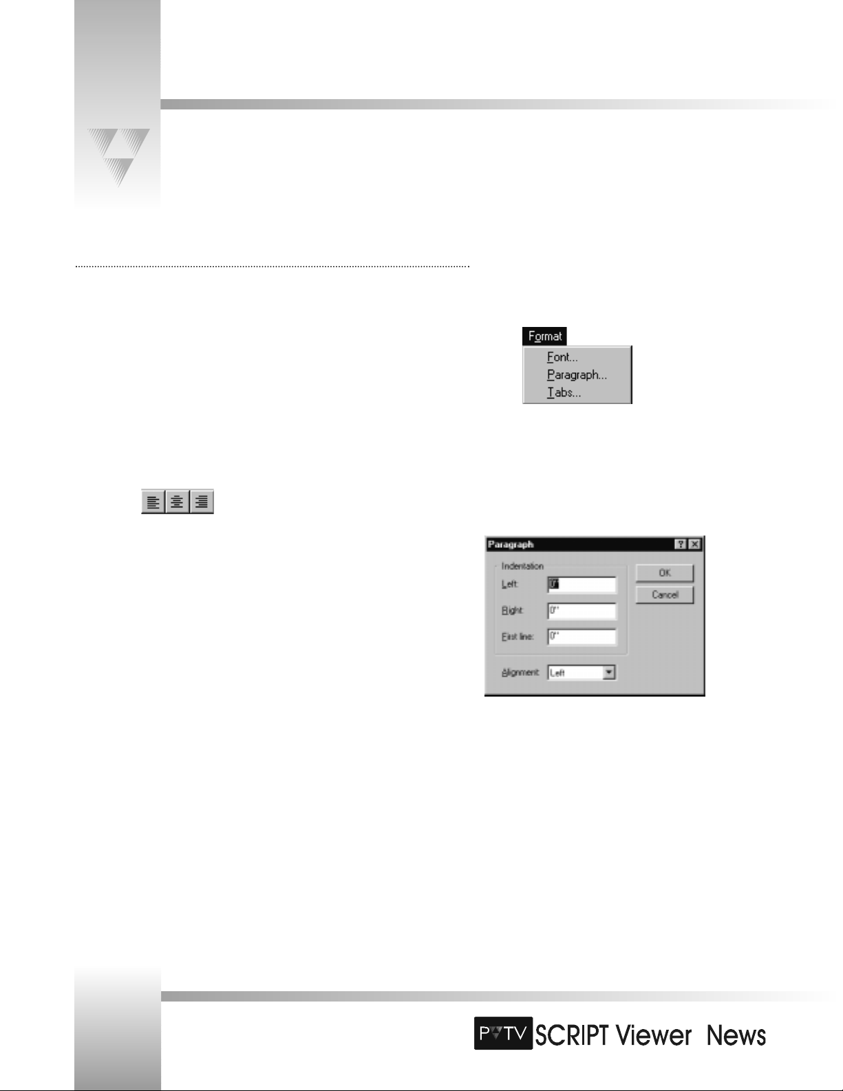
Setting Paragraph Characteristics
You can use the Paragraph dialog box to set margins and to change the text alignment in
the SCRIPTedit window.
To set margins and indentations (using the Paragraph dialog box):
1. Select Paragraph from the Format menu. This opens the Paragraph dialog box.
2. Enter (in inches) the Left and Right margins and the First Line indentation in the
boxes.
To change text alignment:
• Dialog Box: Select Left, Center, or Right Alignment in the list. Click [OK].
• Toolbar: Use the following toolbar buttons to align the text to the left, center, or
right:
.
Page 34
Installation and Operations Manual • © 1999 ParkerVision, Inc.
Page 37

TM
Page 35
SCRIPTedit Basics
Setting Tabs
You can use the Tab dialog box to set tabs in the SCRIPTedit window.
To set tabs (using the Tabs dialog box):
1. Select Tabs from the Format menu.
2. Enter the tab setting (in inches) in the Tab stop position box.
3. Click [Set].
4. Click [OK].
To remove a single tab, select it, and click [Clear]. To remove all tabs, click
[Clear All].
Finding and Replacing Text
When working with a script, you may find that you need to change a word that is repeated
throughout the script. SCRIPTedit’s find/replace function allows you to easily search for the
incorrect words and replace them with the corrected ones.
Find: Use the Find function to search for specific words or characters.
1. Enter the search text in the Find what box.
2. Select Match whole word or Match case, if needed.
3. Click [Find Next].
Replace: Use the Replace function to search and replace words or characters.
1. Enter the search text in the Find what box.
2. Enter the text you want to replace the search text with in the Replace with box.
3. Select “Match whole word only” or “Match case,” if needed.
4. Click [Find Next].
5. Do one of the following:
• Click [Replace] to replace the highlighted word.
• Click [Replace All] to replace this word throughout the script.
© 1999 ParkerVision, Inc. • Use Your SCRIPT Viewer™ System
Page 38

TM
TM
SCRIPTedit Basics
Saving a Script
To save under the current file name:
1. Click
.
2. Select Save from the File menu.
To save a script under a different file name:
1. Select Save As from the File menu. This opens the Save As dialog box.
2. If needed, select a different directory in the Save in box:
• Click the attached arrow, click to select a drive, then double-click a different
directory.
• All directories, subdirectories, and script files (*.RTF) for the selected drive or
directory are listed.
3. In the File name box, enter the file name with a .RTF extension.
4. Click [Save].
To save the file over an existing Script, select a file name, and click [Save].
Printing a Script
To print a script:
1. Select one of the following options from the File menu:
• Print - Prints the Script to the printer.
• Print Preview - Preview the Script before printing.
• Page Setup - Setup the paper size and source, orientation, and margins.
To setup the page:
1. Select Page Setup from the File menu.
2. In the Paper area, select one of the following options:
• Size - Specifies the size of paper you want to print on.
• Source - Specifies where the paper you want to use is located in the printer.
3. In the Orientation area, click:
• Portrait for vertical orientation.
• Landscape for horizontal orientation.
4. Enter the Left, Top, Right, and Bottom margins.
5. Click [OK].
Page 36
Installation and Operations Manual • © 1999 ParkerVision, Inc.
Page 39
TM
Page 37
SCRIPTedit Basics
© 1999 ParkerVision, Inc. • Use Your SCRIPT Viewer™ System
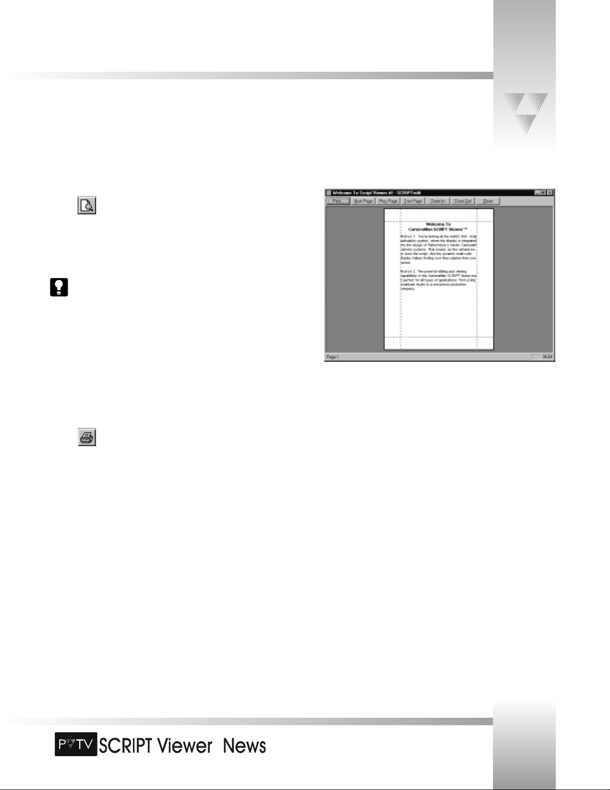
Preview the Script
1. Click on the SCRIPTedit toolbar to preview a script before printing.
2. To zoom in, click the cursor anywhere in the text. The cursor changes from a hand to
a magnifying glass.
3. Click again to zoom in more.
4. Click again to return to the original size.
You also can click [Zoom In] or [Zoom Out] to change the preview.
5. To change pages, click [Next Page] or [Prev Page].
6. To view two pages in the Preview window, click [Two Page].
7. To switch back, click [One Page].
8. Click [Print] to open the Print dialog box.
9. Click [Close] to return to the main SCRIPTedit window.
Print the Script
To print the entire Script directly to the printer:
1. Click .
To print a Script using the Print dialog box:
1. Select Print from the File menu. This opens the Print dialog box.
2. In the Printer area, make sure the correct printer Name is selected. If not, select the
correct printer.
3. In the Print range area, select All, or select Pages and enter the pages you want to
print.
4. Enter the Number of copies you want to print.
5. Click [OK].
Page 40

TM
Loading a Script into SCRIPTview
To load a script after opening, creating or editing a script:
1. Select Save from the File menu in SCRIPTedit, or click .
2. Click [Yes] in the Load the Script? dialog box.
3. If changes were saved before exiting, a message will ask if you want to load the
script into SCRIPTview. Answer Yes to load the script, or No to return to the original
script in SCRIPTview.
To load a script into the viewer only:
1. Select File / Open from the Viewer menu.
2. Select the file you wish to load into the viewer.
3. Click [Yes] when asked to load the script.
Activating the miniVIEWER
The miniVIEWER is a small window that enables you to preview the running script. To take full
advantage of the miniVIEWER’s functionality, you will need to be able to see the following:
• The miniVIEWER window: Select Show miniVIEWER Window from the Viewer menu
(a check appears).
• The SCRIPTview toolbar: If the toolbar is not showing, select Show SCRIPTview
Toolbar from the Viewer menu. The toolbar appears in the SCRIPTedit toolbar area.
To close the miniVIEWER window:
1. Do one of the following:
• Click in the upper-right corner of the window.
• Select Show miniVIEWER Window from the Viewer menu (the check
disappears).
SCRIPTview Basics
Page 38
Installation and Operations Manual • © 1999 ParkerVision, Inc.
Your SCRIPT Viewer system operates using two software applications - SCRIPTedit, which was previously explained, and
SCRIPTview, which actually scrolls the text for the talent. You can access the SCRIPTview controls using the Viewer menu, and/or
icons on the toolbar.
Page 41
TM
Page 39
SCRIPTview Basics
© 1999 ParkerVision, Inc. • Use Your SCRIPT Viewer™ System
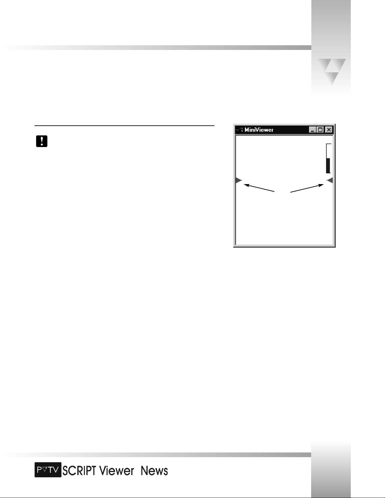
The miniVIEWER Window
The miniVIEWER is available in SCRIPTedit. Any format changes made to the current
script with the MiniViewer toolbar will not be saved to the original file. They are
executed at runtime only and then cleared when the file is closed.
The miniVIEWER is a replica of the SCRIPTview screen. It consists of three key segments:
The scrolling text area.
The script status bar.
The read from carets.
Page 42

TM
TM
SCRIPTview Basics
The SCRIPTView Toolbar
To display or hide the SCRIPTview toolbar, select Show SCRIPTview Toolbar from the View
menu. If the toolbar is active, this option is checked on the menu. Click the appropriate toolbar
button to format or control the script on the SCRIPTview display or the miniVIEWER. Place the
cursor over a button to view a description of the function.
Run Script: From the SCRIPTview toolbar, you may cue, run/pause, or stop the Script from
scrolling.
Cue Script: prepares the script to run
Run Script
Pause Script
Format Script: You can change a script’s font or format through the SCRIPTview toolbar
without changing the original script file. When you apply formatting in SCRIPTview, the format
changes made in this window will temporarily override the formatting in SCRIPTedit.
Permanent changes to the script must be made and saved in SCRIPTedit.
Toggle All Caps: Changes the script from normal format to all capital letters.
Increase, decrease, or reset the font size.
Align Text Left or align text center.
Control Scrolling: Use the SCRIPTview toolbar buttons to change the scroll speed, move the
caret up or down, or reverse the scrolling direction of the script.
Increase the scroll speed or decrease the scroll speed.
Move the caret up or down to change the Script’s line placement. The caret
also controls when Script commands are initiated.
Reverse scroll.
Clear: Clears the SCRIPTview monitor display.
Set Background Color: allows for selection of background color of SCRIPT Viewer.
Page 40
Installation and Operations Manual • © 1999 ParkerVision, Inc.
Page 43

TM
Page 41
SCRIPTview Commands
Now that are acquainted with the MiniViewer and the basic SCRIPTview commands, you can begin adding script commands to
your scripts. Script commands allow you to apply script actions (i.e., cue, play, pause, etc.) at certain points in your script. Script
commands can even trigger events in your live production if you’re using PVTV STUDIO, ParkerVision’s automated live production
system.
Inserting SCRIPT Commands
To insert a script command:
1. Place the cursor where you’d like the command to appear in the script.
2. Click the icon representing the command you wish to place there (see below), or
choose the appropriate command from the Insert menu.
3. Enter the length of time for the cue, or delay using the dialog boxes.
Cue Command: Enters the startup delay
time for the Script.
Delay Command: Inserts a delay time
anywhere in the Script.
Pause Command: Inserts a pause - this will pause the Script until it is re-started.
TMacro Step Command: Sends a
message to PVTV STUDIO to continue the
Transition Macro. You can designate an
ID number for TMacro Step Command.
© 1999 ParkerVision, Inc. • Use Your SCRIPT Viewer™ System
Page 44
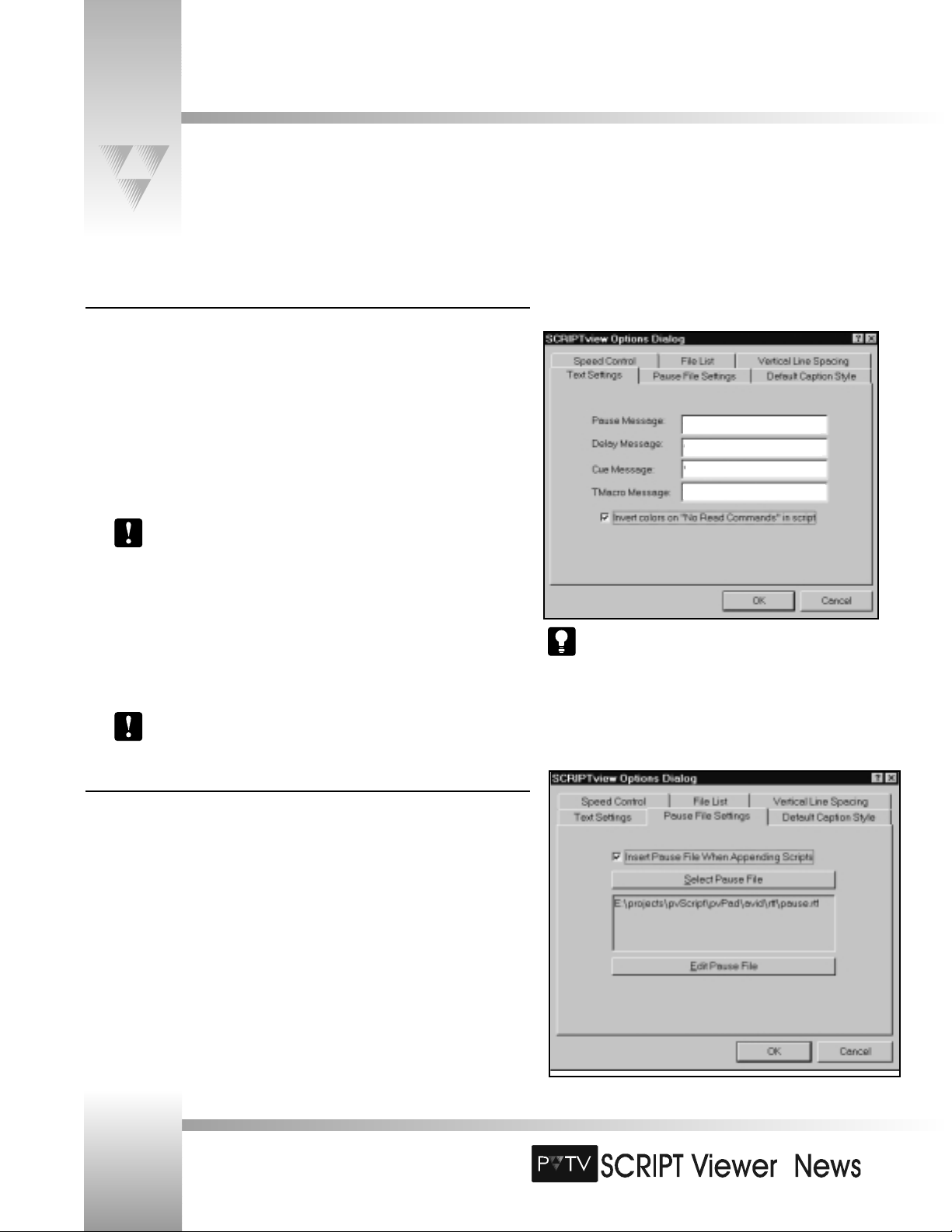
When the “Invert Colors” box is selected, the background and
foreground colors are switched to separate the “No
Read Commands” from the actual script.
TM
Setting SCRIPTview Options
Select Options from the Viewer menu to display the SCRIPTview Options dialog box. This dialog box enables you to configure
various aspects of your SCRIPT Viewer.
Page 42
Installation and Operations Manual • © 1999 ParkerVision, Inc.
<<Pause Here>>
<<Wait A Second>>
<<Sit Up/Smile/Get Set>>
<<Macro Step Here>>
Text Settings
On the previous page, you learned about how to insert script commands into your script.
SCRIPT Viewer also enables you to change how each command appears on the SCRIPTview
monitor.
The default text settings are:
• Pause Message: << Pause >>
• Delay Message: << Delay %u >>
• Cue Message: << Start %u >>
• TMacro Message: << TMacro Step: %u >>
%u represents the amount of time you enter into the Cue Command dialog
box.
To change a text setting:
1. Open the SCRIPTview Options dialog box.
2. Click the Text Settings tab.
3. Enter the word(s) you’d like to appear in the text box beside each message setting.
4. Click [OK].
These changes only affect the text on the viewer. They do not affect the text in
the SCRIPTedit window.
Pause File Settings
The Pause File is the RTF file appended to the end of the Active Script after using the APPEND hotkey.
While it is called the Pause File and may contain a Pause Message, it may contain any text or SCRIPTview
command and may also be considered a Script Seperator.
Page 45

TM
Page 43
Setting SCRIPTview Options
Speed Control
• Delay Adjustment: The number of units to adjust the script delay each time that the
speed adjustment is made.
• Script Delay: The number of micro-seconds delay between scan lines. A lower number
represents higher speeds.
• Minimum Delay: The fastest speed the script will scroll.
• Maximum Delay: The slowest speed the script will scroll.
To change a setting:
1. Open the SCRIPTview Options dialog box.
2. Click the Speed Control tab.
3. Enter the desired values by each setting.
4. Click [OK].
File List
The File List is activated from the keypad with the Select button. These two options
determine the type of window that displays when you press this button. Traverse the list with
the Faster/Slower buttons. Select the desired file with the Run/Pause button.
• Display 16 most recent files: A window is generated which shows the last 16 files
that were loaded into the viewer.
• Display File Directory: A window is displayed, allowing you to select files from the
directories on the hard drive. Enter the default directory to display in the Directory:
box.
To change the file list setting:
1. Open the SCRIPTview Options dialog box.
2. Click the File List tab.
3. Select a File List Option.
4. Click [OK].
© 1999 ParkerVision, Inc. • Use Your SCRIPT Viewer™ System
Page 46

TM
Setting SCRIPTview Options
Vertical Line Spacing
The Vertical Line Spacing tab enables you to increase and decrease the spacing between lines
displayed on the viewer. The increase is a percentage of the current line height.
To change the Vertical Line Space:
1. Open the SCRIPTview Options dialog box.
2. Click the Vertical Line Space tab.
3. Enter the Line Spacing percentage you want.
4. Click [OK].
Default Caption Style
The Default Caption Style tab enables you to control the various options available to
the Closed-Caption device you may be using. Refer to Appendix C for details
concerning installtion and useage of your Closed-Caption device and SCRIPTviewer.
Page 44
Installation and Operations Manual • © 1999 ParkerVision, Inc.
Page 47

TM
Page 45
Testing PVTV SCRIPT Viewer - STUDIO Functionality
This section is intended to guide you through a basic functional test of the optional PVTV SCRIPT Viewer teleprompting
system, and its operation within PVTV STUDIO. If your system does not include PVTV STUDIO, proceed to the next topic.
For complete operational instructions on PVTV STUDIO, refer to the PVTV STUDIO Installation and Configuration Manual.
© 1999 ParkerVision, Inc. • Use Your SCRIPT Viewer™ System
This is a test script. I am only writing
this script to test the communications
between my PVTV STUDIO system,
and my PVTV SCRIPT Viewer
teleprompting
This is a test script. I am
only writing this script
to test the
communications
between my PVTV
STUDIO system, and
my PVTV SCRIPT
Viewer teleprompting
system.
The Script Viewer’s
remote machine address
should match the PVTV
STUDIO’s local machine
address and vice versa.
Double-click
here
1. Power-up PVTV STUDIO.
2. Enter “This is a test script. I am only writing this script to test the
communications between my PVTV STUDIO system, and my PVTV SCRIPT
Viewer teleprompting system” in the SCRIPTedit window.
3. On the SCRIPTedit monitor,select Show miniVIEWER Window from the
Viewer menu. The miniVIEWER window appears.
4. Double-click the miniVIEWER window. The Network Status dialog box
appears. In this box, under the Remote tab, note the contents of the
Remote Machine Address box. Also note the contents of the Local
Machine Address box under the Local tab.
Page 48

TM
Testing PVTV SCRIPT Viewer - STUDIO Functionality
5. Return to the mouse controlling PVTV STUDIO. On the left GUI monitor, about ¾ down
the left side you will see another miniVIEWER window. Double-click this window. Another
Network Status dialog box appears.
6. Once again, note the Remote Machine Address. This address should be identical to the
address displayed in the Local Machine Address box in the PVTV SCRIPT Viewer system.
Conversely, the Local Machine Address of PVTV STUDIO will match the Remote
Machine Address displayed in PVTV SCRIPT Viewer.
7. Returning to PVTV SCRIPT Viewer, click .
8. When asked if you want to load the Editor Script into the Viewer, click [Yes].
9. Return to the miniVIEWER window in PVTV STUDIO. You should see your script. If you
do, then you have successfully tested the interaction of PVTV SCRIPT Viewer with PVTV
STUDIO.
Page 46
Installation and Operations Manual • © 1999 ParkerVision, Inc.
This is a test script. I
am only writing this
script to test the
communications
between my PVTV
STUDIO
Page 49
TM
Page 47
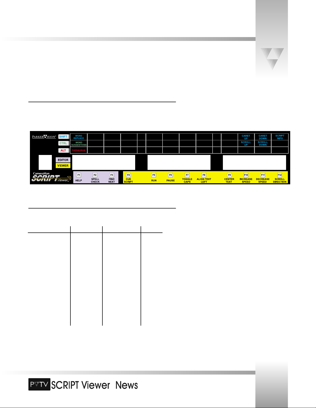
The Keyboard Template Overlay
Included with your SCRIPT Viewer system is a quick-reference keyboard template overlay designed to provide an at-a-glance lookup
of function editing and operation hot keys.
Positioning the Overlay
Place the overlay on the SCRIPT Viewer keyboard, with the ESC key fitting inside the hole on
the far left side of the overlay. This will result in the F1 through F12 function keys fitting inside
the remaining holes in the overlay.
Function Key Shortcuts
Most functional operations for SCRIPTedit and SCRIPTview are noted on the overlay.
Key Shift Ctrl Alt
F1: Help Word Replace Word Suggestions Thesaurus
F2: Spell Check
F3: Find Next
F4: Cue Script
F5: Run
F6: Pause
F7: Toggle Caps
F8: Align Left Text
F9: Center Text
F10: Increase Speed Caret Up Scroll Up
F11: Decrease Speed Caret Down Scroll Down
F12: Scroll Direction Script Info
© 1999 ParkerVision, Inc. • Use Your SCRIPT Viewer™ System
Page 50

TM
Appendix A: Specifications
SCRIPT Viewer System Specifications:
Processor. . . . . . . . . Intel Pentium MMX™
Operating System. . . Microsoft Windows NT 4.0™ w/Service Pack 3
Monitor. . . . . . . . . . 15” VGA color
VGA outputs . . . . . . Two 15-pin HD
VGA DA . . . . . . . . . One in/Four out
Internal Drives . . . . . Hard drive- 3.1 GB or better
3.5” floppy
CD-ROM
Case . . . . . . . . . . . . Rack-mount with locking front door
Communications. . . . Remote Diagnostics Port
Network Port
Dimensions . . . . . . . H: 7” (17.78 cm) W: 19” (48.26 cm)
L: 18” (45.72 cm)
Weight . . . . . . . . . . 36.50 pounds (16.56 Kilos)
Temperature Range:. 32°- 100° F (0°-37.78° C)
Humidity Range: . . . . 0-95% Non-condensing
SCRIPT Viewer Display Specifications:
Type . . . . . . . . . . . . LCD-TFT (AM)
Format . . . . . . . . . . 1024X768 pixels, 16.8 million colors
Size. . . . . . . . . . . . . 12.1" diagonal
Contrast Ratio . . . . . 150:1
Response Time. . . . . 40 ms
Brightness . . . . . . . . 200 cd/m2
Power . . . . . . . . . . . 30 watts
Connection . . . . . . . 5’ cable with standard VGA 15-pin connector
SCRIPT Viewer Keypad
Control Features: . . . all CAPS, L/C Justification, font size, caret adjust,
script speed, cue script, run, pause, script select
Wireless Mode:
RF Range: . . . . . . . . 60’ (18.28 m) from Camera (standard)
Power:. . . . . . . . . . . (2) AA DURACELL® Battery
Hard-Wired Mode:
Range:. . . . . . . . . . . 250’ (76.2 m) from Camera (standard)
Power:. . . . . . . . . . . Supplied through cable
Dimensions: . . . . . . . L: 7” (17.78cm) W: 2.2” (5.59cm)
H: .85” (2.16cm)
Page 48
Installation and Operations Manual • © 1999 ParkerVision, Inc.
Page 51

TM
Page 49
Appendix B: Warranty Information
© 1999 ParkerVision, Inc. • Meet Your SCRIPT Viewer™
ParkerVision 90-Day Limited Warranty
• ParkerVision warrants to the end user that this product will be free from
defects in material and/or workmanship for a 90-day period commencing
on the date of delivery, except where expressly noted.
• Proof of Purchase: ParkerVision’s Authorized Dealer’s dated bill of sale
must be retained as evidence of the date of purchase to establish
warranty eligibility.
• ParkerVision will correct all defects in material or workmanship, or any
failure of the system to perform to specifications during the warranty
period, at no charge for parts and labor.
• The original purchaser must notify ParkerVision, in writing, before the
warranty period has expired in the event of a defect in material or
workmanship, or failure of the system to perform to specifications.
• If damage occurs in the shipment from the ParkerVision factory,
ParkerVision must be notified within five (5) working days of receipt of
the product in order to make a claim.
• ParkerVision is not obligated at any time to provide the purchaser with a
substitute unit.
• The warranty is not extended due to purchasing new products and/or
upgrading your original product.
• The warranty is non-transferable.
• Purchaser’s failure to make a claim as provided above, or continued use
of the product, shall constitute an unqualified acceptance of such
product and a waiver by purchaser of all claims.
Product Warranty Registration Form
• The warranty period begins the day your ParkerVision product is received.
• Product Warranty Registration is required to ensure that your product
receives prompt attention if warranty work is ever necessary.
The Warranty is voided if...
• The product is damaged in shipping other than the original shipment
from the ParkerVision factory.
• The product is used outside of the specifications or operating guidelines,
as outlined in the ParkerVision product manuals.
• The product has sustained physical damage from misuse or abuse.
• The product has sustained damage due to a natural disaster such as fire,
lightning, earthquake, etc.
• The product is damaged by non-ParkerVision peripherals.
• A person not authorized by ParkerVision has attempted/or has serviced
the equipment.
• The product’s identification (serial numbers, trademarks, etc.) is removed,
defaced, or altered.
• Non-ParkerVision software is loaded onto the CPU.
Return Policies
For return procedures, contact your authorized ParkerVision Reseller.
Page 52
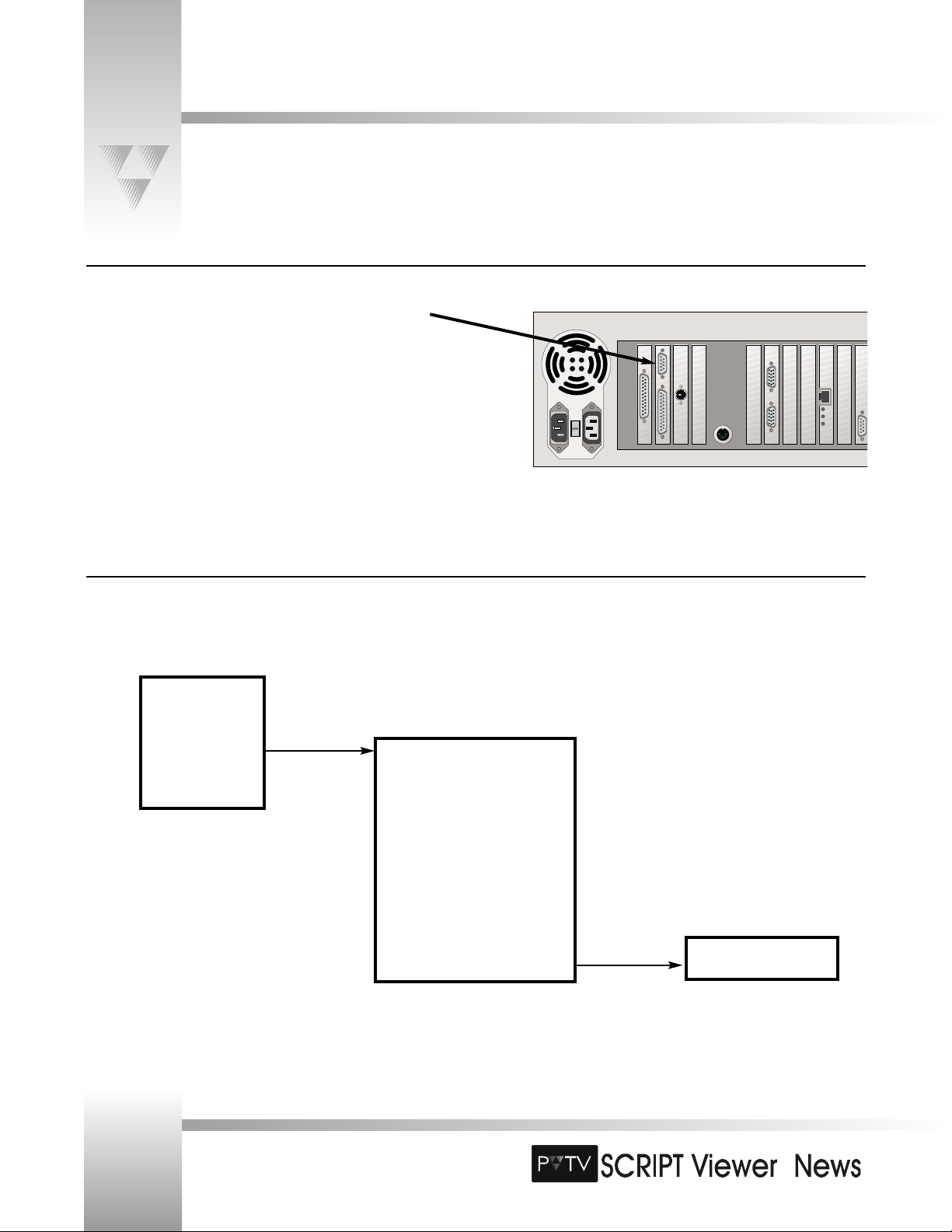
TM
Connect the Closed-Caption Device to SCRIPTviewer
Install your CC device close enough to the SCRIPTviewer to be able to attach it’s control port to Serial Port 1 on the SCRIPTviewer CPU. (Fig. C-1)
Insert CC device into Video Stream
The CC device resides between the STUDIO Program Out and the transmitter.
Page 50
Installation and Operations Manual • © 1999 ParkerVision, Inc.
Appendix C: Closed-Caption Installation and Operation
SCRIPTviewer provides support for both Link and EEG closed-caption devices.
STUDIO
Program
Out
Transmitter
Video In
CC Device
Video Out
Fig. C-1
Fig. C-2
Page 53

TM
Page 51
Setting the CC Device Defaults
• Encoder Model - the type of CC device being used. Currently, Link & EEG devices are
supported.
• Encode Caption On - the channel being used for CC output.
• Viewable Lines - the number of CC text lines visible.
• Text Color - the color of the CC display text.
• Left Margin - the width of the left (open) margin in columns.
Used for indenting CC text.
• Sustain Time - the duration for the display of CC text (in
seconds).
• Bottom Margin - the width of the bottom margin between the
CC text and the screen edge expressed in lines of text.
© 1999 ParkerVision, Inc. • Meet Your SCRIPT Viewer™
Appendix C: Closed-Caption Installation and Operation
Fig. C-3
Page 54

TM
Page 52
Installation and Operations Manual • © 1999 ParkerVision, Inc.
Appendix D: Standard AP NewsCenter Installation and Operation
Support for AP NewsCenter is provided via a specialized FTP client and a standard TCP/IP network connection. Refer to the
NewsCenter manuals for installation and configuration of your AP NewsCenter system.
Accessing the AP NewsCenter System from SCRIPT Viewer
1. Select AP Setup from the ScriptList menu in the ScriptEditor. (Fig. D-1)
2. If you do not have a CG in your system select Inhibit CG page creation. (Fig. D--2)
3. The Conversion Directory is where the CG command definitions are located. Note
the pathname prefixed by \\. This indicates a remote machine.
4. Enter the CG start Page Index number and the Machine ID if the defaults are not
correct. In this example, the CG pages are created beginning with 5000.
Fig. D-1
Fig. D-2
Page 55

TM
Page 53
© 1999 ParkerVision, Inc. • Meet Your SCRIPT Viewer™
Appendix D: Standard AP NewsCenter Installation and Operation
Converting AP NewsCenter rundowns into SCRIPT Viewer Scripts
1. Select AP Conversion from the ScriptList menu in the ScriptEditor. (Fig. D-3)
2. Enter the Conversion Directory in which to store the converted scripts. (Fig. D-4)
Note that this is not the same as the Conversion Directory shown in the Setup dialog.
3. You may adjust the bold/no bold and font size at which to display the Scripts in
SCRIPTview.
4. Open Windows NT Explorer.
5. Locate the AP rundown file to be converted and drag it onto the ScriptList dialog
(Fig. D-6). SCRIPTviewer automatically converts the AP rundown file into Script RTF
files with which you can organize and build your production.
Fig. D-3
Fig. D-4
Fig. D-5
Fig. D-6
Page 56

TM
Appendix E: AvStar Installation and Operation
Set Up the AvStar Conversion Options
1. Select AvStar Setup from the ScriptList menu in the ScriptEditor.
(Fig. E-1)
2. The Conversion Setup dialog controls the Avstar- CG options and directory
monitoring refresh rates.
If you do not have a CG in your system select Inhibit CG page creation. (Fig. E-2)
Otherwise, the CG Template Directory box displays the path to the CG’s Avid
directory where CG pages will be created.
Page Index default for CG page numbering is 5000.
Machine ID indicates the number of the CG in the system.
Script Refresh Time defaults to 5 seconds and refers to the monitoring cycle time if
Monitor Continously is selected in Fig. E-5. If Monitor Continously is not selected,
you may refresh the ScriptList directory tree at any time by pressing the Refesh
button.
Fig. E-1
Fig. E-2
Page 54
Installation and Operations Manual • © 1999 ParkerVision, Inc.
Page 57

TM
Fig. E-5
Support for AvStar is provided via a specialized FTP client and a standard TCP/IP network connection. Refer to the AvStar manuals
for installation and configuration of your AvStar system.
You will need to provide a SERVER name, USER name & PASSWORD (if any) to SCRIPTviewer in order to connect to the
AvStar system.
Appendix E: AvStar Installation and Operation
Logging In to the AvStar System from SCRIPT Viewer
1. Select AvStar Conversion from the ScriptList menu in the ScriptEditor. (Fig. E-3)
2. You must supply a USER, SERVER and PASSWORD (if
any) in order to login to the AvStar system. Your system administrator can supply you
with these. The default display directory is shown in the Show Directory box. You may
change this at any time and the Login dialog will remember it. (Fig. E-4)
You may also select the font size and bold/no bold state of the text imported into
SCRIPTviewer. The defaults are as shown.
3. Once logged in, the directory structure (tree) of the Show Directory will be displayed
in the ScriptList dialog window. You may open and close these directories as you would
in NT Explorer. (Fig. E-5)
Monitor Continously refers to the ability of SCRIPTviewer to automatically look for
changes in the selected directory and update the directory tree.
Fig. E-3
Fig. E-4
Page 55
© 1999 ParkerVision, Inc. • Meet Your SCRIPT Viewer™
Page 58

Page 56
Appendix F: Advanced AP NewsCenter Installation and Operation
Support for AP NewsCenter is provided via a specialized FTP client and a standard TCP/IP network connection. Refer to the
NewsCenter manuals for installation and configuration of your AP NewsCenter system.
Set Up the AP NewsCenter Conversion Options
1. Select AP Setup from the ScriptList menu in the ScriptEditor.
(Fig. F-1)
2. If you do not have a CG in your system select Inhibit CG page creation. (Fig. F-2)
Otherwise, the CG Template Directory box displays the path to the CG’s AP directory
where CG pages will be created.
3. The Conversion Directory is where the CG command definitions are located.
Note the parameter prefixed by \\. This indicates a remote machine.
4. Enter the CG start Page Index number and the Machine ID if the defaults are
not correct.
The Page Index Number default for CG page numbering is 5000.
The Machine ID indicates the number of the CG in the system.
© 1999 ParkerVision, Inc. • Meet Your SCRIPT Viewer™
TM
Fig. F-1
Fig. F-2
Page 59
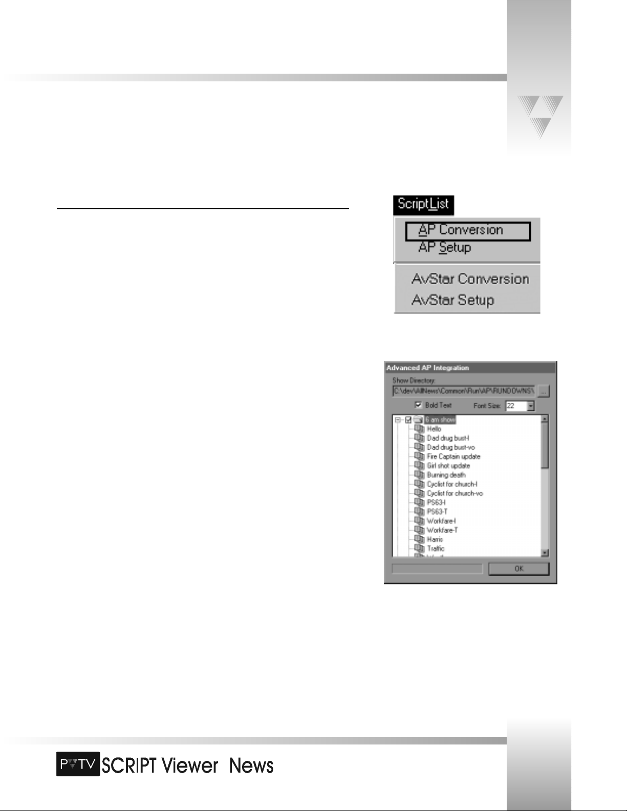
Page 57
Appendix F: Advanced AP NewsCenter Installation and Operation
Accessing the AP NewsCenter Systemfrom SCRIPT Viewer
1. Select AP Conversion from the ScriptList menu in the ScriptEditor (Fig. F-3).
This will open the Advanced AP Integration window.
2. The user must point to a Show Directory address. After locating and selecting
the AP Rundown file , double-click on it to load it in the Advanced AP Integration
dialog window.
3. Once the (tree) directory structure of the Show Directory is displayed in the
Advanced AP Integration dialog window, you can open and close the directories as
you would in Windows NT Explorer.
You may also select the font size and bold/no bold state of the text imported into
SCRIPT Viewer.
© 1999 ParkerVision, Inc. • Meet Your SCRIPT Viewer™
TM
Fig. F-3
Fig. F-4
Page 60

© 1999 ParkerVision, Inc.
Literature Part Number L1102101
(
Ref# LPMSVNUS
)
Revision A
 Loading...