

Page 1
Stand-Alone Controller
RSE 1
Customer‘s Manual
Page 2

Pub
lished by
BTS Media Solutions GmbH
Brunnenweg 9
D-64331 Weiterstadt, Germany
P.O. Box 1165
Tel: +49 (0) 6155-870-0
Fax: +49 (0) 6155-870-300
Copyrights
Für diese Unterlage behalten wir uns alle
Rechte vor (Gemäß DIN 34).
Technische Änderungen im Zuge der
Weiterentwicklung vorbehalten.
BTS Media Solutions GmbH 2001
Copying of this document and giving it to
others, and the use or communication of
the contents thereof, are forbidden without
expressed authority. O ffenders are liable to
the payment of damages. All rights are reserved in the event of the grant of a patent
or the registration of a utility model or design.
Liable to technical alterations in the course
of further development.
Toute communication ou reproduction de
ce document, toute exploitation ou communication de son contenu sont interdites,
sauf autorisation expressé. Tout manquement à cette règle est illicite et expose son
auteur au versement de dommages et
intérêts. Tous nos droits sont réservés
pour le cas de la délivrance d’un brevet ou
de l’enregistrement d’un modèle d’utilité.
Sous réserve de modification au cours de
l’évolution technique.
Page 3

Revision Report
Stand-Alone Controlle RSE 1
Documentation Order Number
Customer’s Manual
Before reading the entire
manual, please check for any
supplements at the end
of the manual.
Item Rev Date SerNoPages affected Contents Remarks
1 0 10.01 100 all Customer’s Manual 1st Edition
Page 4

CONTENTS
Revision Report
Declaration of Conformity
1. Applications 1. . . . . . . . . . . . . . . . . . . . . . . . . . . . . . . . . . . . . . . . . . . .
2. Technical Data 3. . . . . . . . . . . . . . . . . . . . . . . . . . . . . . . . . . . . . . . . . .
3. Installation 7. . . . . . . . . . . . . . . . . . . . . . . . . . . . . . . . . . . . . . . . . . . . .
ContentsStand-Alone Controller RSE 1
Page
2.1 Mechanical Dimensions 5. . . . . . . . . . . . . . . . . . . . . . . . . . . . . . . . . . . . .
3.1 Safety Instructions 7. . . . . . . . . . . . . . . . . . . . . . . . . . . . . . . . . . . . . . . . .
3.2 Mounting into a Cabinet 8. . . . . . . . . . . . . . . . . . . . . . . . . . . . . . . . . . . . .
3.3 General Grounding Requirements 9. . . . . . . . . . . . . . . . . . . . . . . . . . .
3.4 Connection Unit 13. . . . . . . . . . . . . . . . . . . . . . . . . . . . . . . . . . . . . . . . . . .
4. Pin Assignments 15. . . . . . . . . . . . . . . . . . . . . . . . . . . . . . . . . . . . . . .
5. Network Configuration 17. . . . . . . . . . . . . . . . . . . . . . . . . . . . . . . . .
5.1 Advanced DD35 SD / Seraph HD Configuration 17. . . . . . . . . . . . . .
5.1.1 DD35 with GUI-PC 18. . . . . . . . . . . . . . . . . . . . . . . . . . . . . . . . . . . . . . . . . .
5.1.2 DD35 SD / Seraph HD with two Control Panels 20. . . . . . . . . . . . . . . . .
5.1.3 DD35 SD / Seraph HD with RSAT 2 and RSE 1 22. . . . . . . . . . . . . . . . .
5.1.4 DD35 SD / Seraph HD Simulcasting 24. . . . . . . . . . . . . . . . . . . . . . . . . .
5.1.5 Two Complete Systems 26. . . . . . . . . . . . . . . . . . . . . . . . . . . . . . . . . . . . .
6. Connecting a RSAT Panel to the RSE1 29. . . . . . . . . . . . . . . . . . .
6.1 Creating an Application File for the RSE1 29. . . . . . . . . . . . . . . . . . .
6.2 Loading default Macros from the Sidepanel 31. . . . . . . . . . . . . . . . .
6.3 List of default Macros 32. . . . . . . . . . . . . . . . . . . . . . . . . . . . . . . . . . . . . .
7. Servicing 34. . . . . . . . . . . . . . . . . . . . . . . . . . . . . . . . . . . . . . . . . . . . . .
Rev. 1 / 02.2002
6.4 Saving Environmental Data 33. . . . . . . . . . . . . . . . . . . . . . . . . . . . . . . .
7.1 Exchanging the Lithium Battery 34. . . . . . . . . . . . . . . . . . . . . . . . . . . .
I
Page 5

Contents Stand-Alone Controller RSE 1
II
Rev. 1 / 02.2002
Page 6

1. APPLICATIONS
1. Control Panel Emulation
Install the standard DD35 series control panel software on the RSE1 hardware
platform like on a standard control panel. This RSE 1 will then behave as a
panel where you can connect e.g. a RSAT 1 or RSAT 2 panel and UMD’s or
Aux-CP’s. The panel software supports the first 4 serial ports J1 ... J4, RS485,
bus controller mode. For protocol selections etc. you have to attach a Sidepanel (Sidepanel application on a standard PC or Sidepanel of a real DD35
panel) to the RSE1.
Stand-Alone ControllerRSE 1
Rev. 1 / 02.2002
1
Page 7

RSE 1Stand-Alone Controller
2
Rev. 1 / 02.2002
Page 8

RSE 1 Stand-Alone Controller
2. TECHNICAL DATA
Mechanics 19” Rackframe
Width: 482 mm (19”)
Depth: 251 mm (9.9”)
Height: 43mm (1.7”)
Weight: approx. 7 kg
Voltage supply AC IN voltage 100 – 240 V / max. 500 mA
Line frequency 50 Hz to 60 Hz
Power consumption: approx. 20 W
Touch current ≤ 1 mA
Environmental Operating temperature: +0° C ... 40° C
requirements Storage/transport temp: –40° C ... 85° C
Humidity: ≤ 95%, DIN IEC 68-2-14
non-condensing
Electromagnetic EN 55103-1/-2, EN 55 022, Class B
compability FCC 47 Part 15
Safety VDE 0805, EN 60 950
UL 1419
CSA C.22.60950
Interfaces
• up to 7 intern GPI or 7 intern GPO GPI: Opto coupler , dry contact or active
(free selectable) in, max. 20 V
• 1 Service port (Diagnostic) D-Sub socket 9-pin, female, RS 232C
• LAN port (AUI) D-Sub socket 15-pin, female, by use of
• Genlock 2 BNCs, 50 ohms
• 14 Serial ports D-sub sockets 9-pin, female,
• 1 Serial port D-sub socket 9-pin, female, RS232C
GPO: Silicon switches, potential free,
40V/0.3A.
D-Sub socket 15-pin, female
Thin Coax Transceiver
(IEEE 802.3 /10Base-2), cheapernet,
50 ohms, 150m,
with repeater max. 2.5 km,
connect with
Loop – through
RS485/422
for UMDs, RSAT 2, RSAT 1 or
Auxiliary panels
38.4 kbd max.
Rev. 1 / 02.2002
3
Page 9

Stand-Alone Controller RSE 1
4
Rev. 1 / 02.2002
Page 10
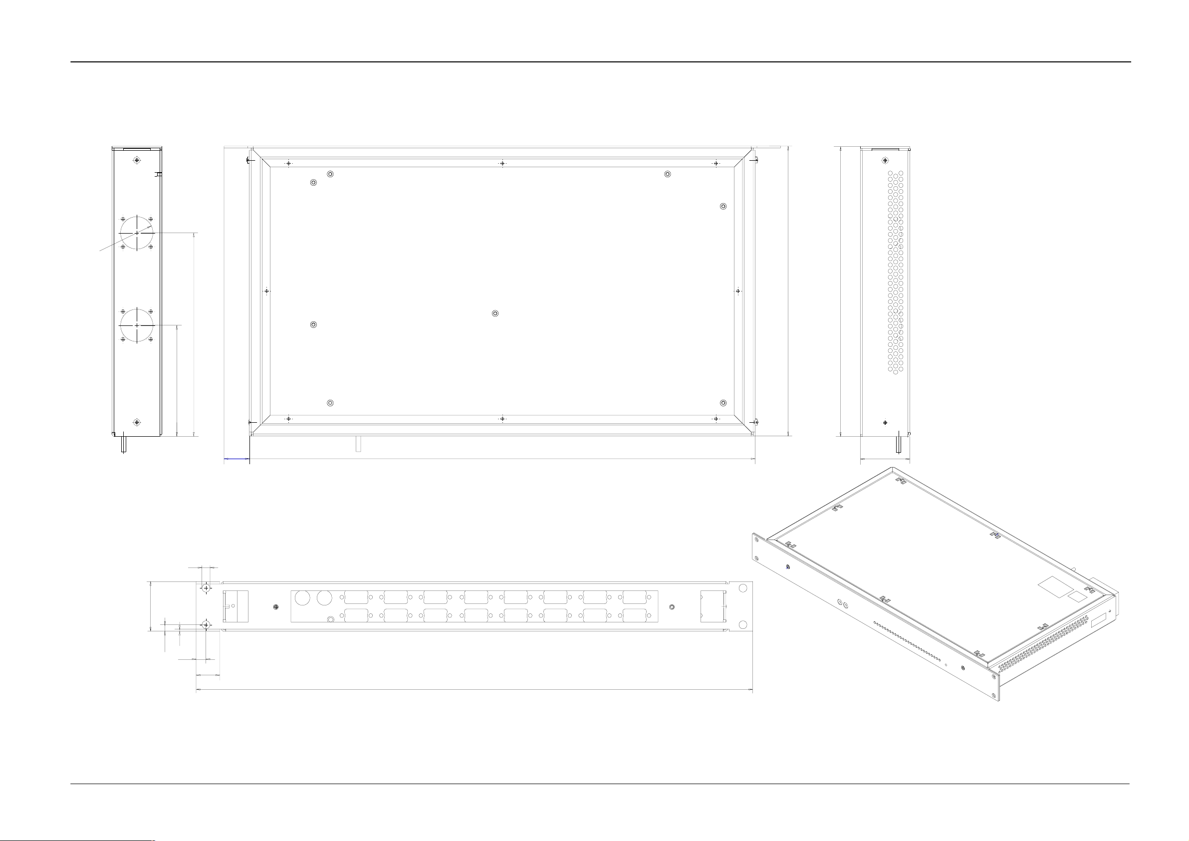
2.1 MECHANICAL DIMENSIONS
28
Stand-Alone ControllerRSE 1
96
7
176
22
438
251
251
43
43
5.62
Fig. 1: Mechanical dimensions
Rev. 1 / 02.2002
2
8.5
20.5
482
All dimensions are [ mm ]
5
Page 11

RSE 1Stand-Alone Controller
6
Rev. 1 / 02.2002
Page 12
RSE 1 Stand-Alone Controller
3. INSTALLATION
3.1 SAFETY INSTRUCTIONS
Caution!
These instructions are for use by qualified personnel only. T o reduce the risk
of electric shock, do not perform any installation other than that contained
in the Operating Instructions unless you are qualified to do so. Refer all servicing to qualified service personnel.
Attention!
Electrostatic sensitive devices on the p. c. boards. Observe the following
precaution for handling:
Handling or mounting the RSE1 unit call for special attention to personal safety.
Personnel should be connected to ground potential via a wristlet (e.g. 3M Wristlet Serial 2200).
Do not touch the p. c. boards during mounting.
Repair the p. c. boards only at static-safe work stations.
Use antistatical protective bags when carrying the p.c. boards.
Attention!
Danger of explosion when the battery is not correctly inserted. Replace the
battery only by a battery from the same manufacturer or by an equivalent
type recommended by the manufacturer.
Protect the environment!
Dead batteries do not belong in the garbage. Hand the used batteries over
to a local disposal place or observe the respective instructions of the
manufacturer!
Rev. 1 / 02.2002
7
Page 13

3.2 MOUNTING INTO A CABINET
General rack mounting instructions
The maximum ambient for this unit is 40°C.
Installing the unit in a closed or multi–unit rack assembly, together with other
units could increase the maximum ambient for this unit.
If the unit is installed in a rack, no ventilation openings should be blocked or
otherwise covered. Ensure a sufficient amount of airflow.
Mounting of the unit in the rack should be such that a hazardous condition is
not achieved due to uneven mechanical loading.
When connecting the unit to the supply circuit be sure that the supply circuit of
the rack is not overloaded. For ratings see chapter Technical Data.
The unit must be grounded to a good earth ground using a wire as specified
by the local electrical code. This wire is attached to the protective earth connector on the rear. For details refer to chapter General Grounding Requirements.
RSE1Stand-Alone Controller
When connecting the unit in a closed or multi–unit rack assembly together with
other units be sure that the summation of the touch (leakage) currents is not
higher than 3.5 mA. In this case the rack must be permanently connected with
an earth terminal. Earth connection is essential before connecting supply voltage! For details see chapter Technical Data.
For installation, Thomson optionally provides a 19-inch cabinet with recommended
mounting accessories. When using cabinets of other manufacturers, observe the
respective mounting instructions.
Note: For installation into a DIN cabinet, adapter pieces of the respec-
tive cabinet manufacturer have to be mounted on both sides of
the lateral fastening flanges.
For relieving the front mounting brackets, the Stand–Alone Controller RSE1 has
also to be supported in the rear part of the frame. The corresponding mounting
parts can be obtained as accessories from the manufacturer of the cabinet-type
rack.
8
Rev. 1 / 02.2002
Page 14

RSE 1 Stand-Alone Controller
3.3 GENERAL GROUNDING REQUIREMENTS
For grounding of the devices, the following three methods are
possible:
PE TE
Protective grounding
1. Grounding with the protective earth of the mains cable which
contains the earthed protective conductors (normally).
2. Additional protective grounding as a potential compensation or earth
conductor with large cross section with PE terminal. The jumper
TE –– PE must not be broken!
The earth connection has to be made before connecting the mains cable!
3. Additional noiseless functional protective earth low on extraneous voltage
with TE terminal. The jumper TE –– PE must be disconnected!
The earth connection has to be made prior to mains cable connections!
Detailed information see in the sections below.
Grounding of the device serves the product safety and meets the requirements in
conformity with safety class I.
The device is connected with the protective earth of the power supply circuit (e.g.
the studio) by means of the mains cable which also contains the earthed protective
conductor PE.
Precondition is an earthed and checked mains socket!
In the device, the power socket is provided with a leading protective contact. This
protective contact is internally connected with the parts to be earthed, e.g. the case.
The effect of the protective earth connection must not be neutralized through the
use of an extension cord without protective earth conductor, through an excessively long cable, nor must its function be disabled in any other way!
Additional earth conductor
At the rear, the device provides separate screw terminals for protective earth and
video earth grounding. On delivery to the customer , PE and TE terminals are joined
by a short-circuit jumper.
The PE terminal, marked by the symbol
ternally connected with the AC IN power socket and the metal case parts.
The TE terminal, marked by the symbol
earth, technical earth), is connected with the reference potentials (ground, GND)
of the internal supply DC voltages and the video earth.
When connecting an additional earth conductor, this connection has always to be
made before connecting the mains cables.
417-IEC-5017 (protective earth), is in-
417-IEC-5018 (video earth, system
Rev. 1 / 02.2002
9
Page 15

RSE1Stand-Alone Controller
Internal wiring
Internal protective earth
PE TE
AC IN
Case
Video earth
(insulated mounting)
For additional grounding of the devices, the following methods are possible:
1. As a potential compensation or as an additional earth conductor with large
cross section:
The jumper between the PE and TE terminal screws must be in place. The central protective conductors of the studio have to be screwed to the PE terminal
screw. The protective conductor should have a cross section greater than that
of the neutral conductor N of the mains cable, however, 2.5 mm
protected installation) (4mm
2
with unprotected installation). Fusing up to 25A.
2
at least (with
Standards: VDE 0800, part 2, table 1/ VDE 0100 T.540 / IEC 364-5-54, 543.1.
Color code of the insulation: green/yellow.
TN-C power systems
2. Additional noiseless functional protective earth FPE (functional earth with protective qualities) low on extraneous voltage:
If required, e.g. in studios with separate protective and technical earth systems,
the jumper between the PE and TE terminals can be broken. In this case, the
central functional earth has to be additionally connected to the TE terminal
screw.
The cross section has to be dimensioned as described above. A low-impedance interconnection of both earth conductors must be provided at the central
studio grounding point or at the earth bus.
Device
Example 1
Protective earth
Device
Example 2
Video earth
Jumper not broken!!
Jumper broken!!
Central
earthing point
10
In case of TN-C power systems (combination of neutral conductor and protective
conductor), it is necessary to observe the regulations in conformity with IEC
364-5-54 (VDE 0100 T-540) and IEC 364-4-41, IEC 364-4-47 (VDE 0100 T.410)
or the applicable national regulations.
Rev. 1 / 02.2002
Page 16

RSE 1 Stand-Alone Controller
Any break of the protective earth conductor inside or outside the device or
disconnection of the protective conductor connector may entail that, in the
event of a failure, the operational safety of the device will no longer be ensured! All mains sockets of the devices being interconnected with signal
cables have to be checked. The protective earth conductors must not be live!
Abbreviations:
FPE = functional protective earth
L = live, outer conductor (phase, R, S, T)
N = neutral conductor
PE = protective earth conductor
TE = technical earth = functional noiseless earth
IEC = International Electrotechnical Commission
VDE = Association of German electrotechnicians and electrical engineers
DIN = German industrial standards
(In conformity with DIN 42 400 or IEC Publication 445)
(earlier designation: PROTECT GND)
color code of the PE wire: green/yellow
(video earth, audio earth with protective earth qualities
color code of the TE wire: black
Rev. 1 / 02.2002
11
Page 17

RSE1Stand-Alone Controller
12
Rev. 1 / 02.2002
Page 18

RSE 1 Stand-Alone Controller
3.4 CONNECTION UNIT
Example:
Stand-Alone Controller RSE 1
rear view
Protective Earth
RS-485 / RS-422 Ports
RS 232
J 8
GPDiagn
AUI
J 17
J 18
N4067
U
T
AC IN
J19
AC POWER IN
100 – 240 V / max. 500mA – 50/60 Hz
Caution:
J 22
J 21
J 20
For continued protection against risk of fire,
repplace only with same type and rating of fuse.
Genlock
LAN TP
RS 485 / RS 422
PE
J 1
J 9
J 2 J 3 J 4 J 5 J 6
J 10 J 11 J 12 J 13 J 14
J 7
J 15 J 16
Fuses
RS-485 / RS-422 Cable
(Option)
Protective Earth
Remote Control Panel RSAT 2
rear view
AC INFuses
RS-485 / RS-422 Cable
(Option)
Marker for port configuration
Factory setting: RS-422/RS-485
Satellite Panel RSAT 1
rear view
Fixture for DC cable
DC IN
any polarity
Befor mounting the Satellite
Panel, switch to ON
Notes:
- It is only possible to connect one RSAT panel to the RSE1, either a RSAT1 panel or a RSAT2 panel.
- The panel software supports only the first four serial ports J1 ... J4, RS485, bus controller mode.
Fig. 2: Example RSAT assignment
Rev. 1 / 02.2002
13
Page 19

Stand-Alone ControllerRSE 1
14
Rev. 1 / 02.2002
Page 20

RSE 1 Stand-Alone Controller
4. PIN ASSIGNMENTS
PORT RS-422/485 Pin Signal
Bus Contr Tributary
1
5
9-pin D-type
female
6
2
3
1
9
4
5
6
7
8
9
Signal Ground
RxA (–) TxA (–)
TxB (+) RxB (+)
Signal Ground
not used
Signal Ground
RxB (+) TxB (+)
TxA (–) RxA (–)
Signal Ground
PORT RS-232 Pin Signal
1
5
9-pin D-type
female
6
2
3
1
9
4
5
6
7
8
9
not used
Transmit Data
Receive Data
not used
Signal Ground
not used
not used
not used
not used
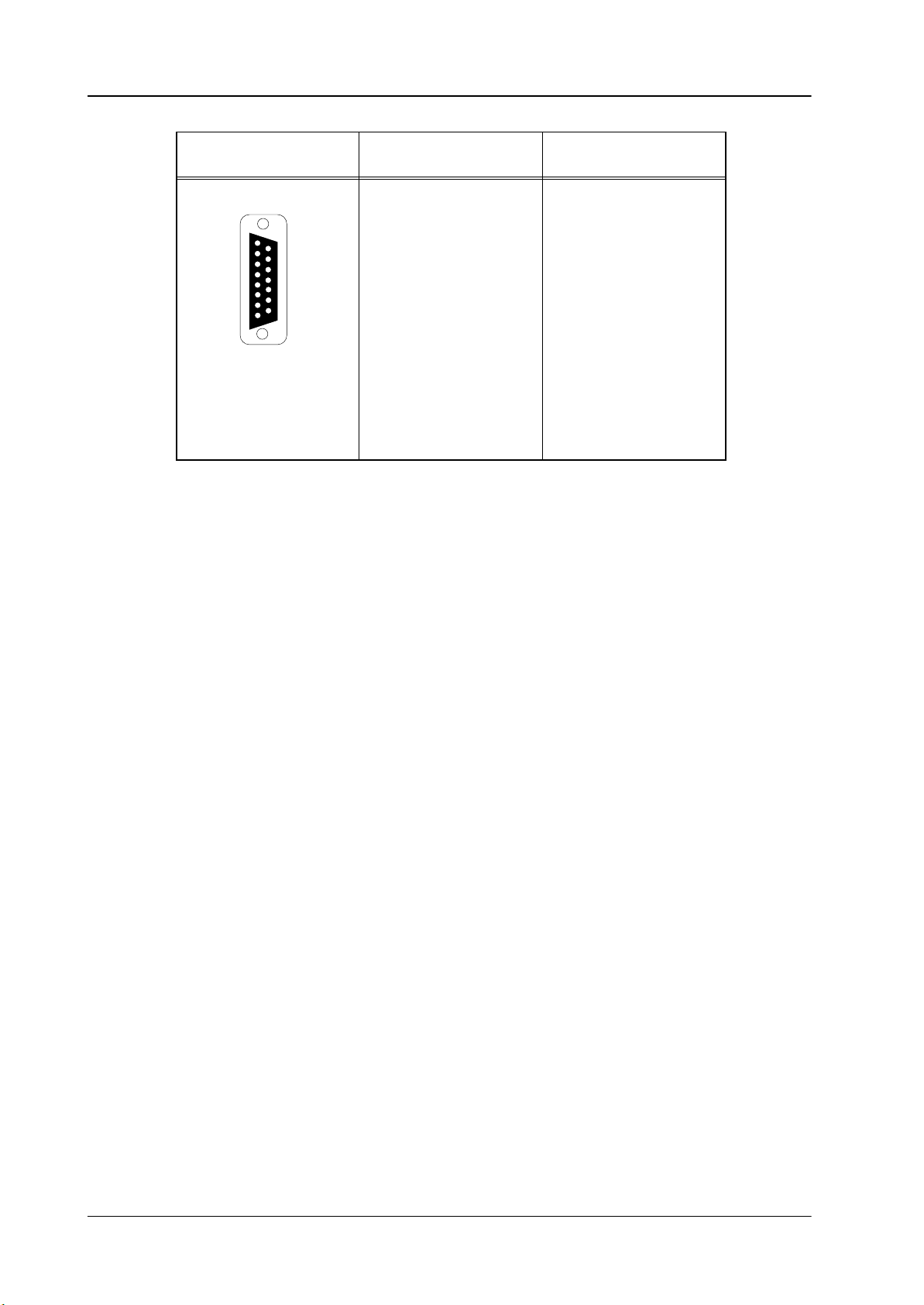
GPI/GPO
Panel
1
8
15-pin D-type
female
15
Pin Signal
1
2
9
3
4
5
6
7
8
9
10
11
12
13
14
15
GPI/O 0–
GPI/O 1–
GPI/O 2–
GPI/O 3–
GPI/O 4–
GPI/O 5–
GPI/O 6–
Signal Ground
GPI/O 0+
GPI/O 1+
GPI/O 2+
GPI/O 3+
GPI/O 4+
GPI/O 5+
GPI/O 6+
Rev. 1 / 02.2002
15
Page 21
Stand-Alone Controller
RSE 1
AUI
Panel
1
8
15-pin D-type
female
15
Pin Signal
1
2
9
3
4
5
6
7
8
9
10
11
12
13
14
15
AUI Ground
AUI CD+
AUI TX+
AUI Ground
AUI RX+
AUI Ground
AUI not used
AUI not used
AUI CD–
AUI TX–
AUI Ground
AUI RX–
AUI +12V
AUI Signal Ground
AUI not used
16
Rev. 1 / 02.2002
Page 22

RSE 1
5. NETWORK CONFIGURATION
Mainframe, panel and panel PC are network devices using TCP/IP protocol. The
devices are shipped with default IP addresses; however, as more resources are
attached to the network, addresses must be changed.
Default address ranges for the DD35 devices:
IP address (class C network) 192.168.0.1
up to
192.168.0.254
The factory configures the following addresses:
mainframe: 192.168.0.70 (incl. two automatically calcula
control panel: 192.168.0.73
sidepanel (panel PC): 192.168.0.74
RSE1 192.168.0.78
Stand-Alone Controller
ted for internal communication ... 71, ... 72)
rotary switch: 0x46
rotary switch: 0x49
rotary switch:0x4C
GUI-PC 192.168.0.77
Please note that the mainframe occupies three consecutive addresses!
Attention:
The IP addresses of the individual devices working on the network must be
different. For mainframe and control panel, the setting can be undertaken directly on the controller board. The lowest address byte can be set in the
range from 0 to 255 with a Hex rotary switch.
The IP address of the panel PC can be set with the Windows 95 or ’98 tool
“Settings/Control Panel/Network” directly.
Note on Windowst registry settings:
The graphical user interface (a.k.a. sidepanel program) writes its registry settings on program close. Changing any setting by regedit therefore is in vain
if the sidepanel program is active. It must be closed before.
5.1 ADVANCED DD35 / SERAPH HD CONFIGURATIONS
This section will explain how to install and configure DD35/Seraph HD systems that
include more devices on the LAN than mainframe and control panel (with built-in
sidepanel).
Rev. 1 / 02.2002
In particular the following configurations will be explained:
DD35/Seraph HD system plus GUI–PC
DD35/Seraph HD system with two control panels
DD35/Seraph HD system with RSAT2 and RSE1 (or RSAT1 and RSE1)
DD35/Seraph HD system with HD/DD simulcasting
Two complete systems
17
Page 23

Stand-Alone Controller
5.1.1 DD35 WITH GUI-PC
This also applies to users of ”DS 0103 Software License for additional Side-Con-
trol”.
5.1.1.1 Schematic
RSE 1
BNC T-type
50 W
Terminator
Mainframe
5.1.1.2 IP Addresses
BNC T-type BNC T-type
Panel
BNC T-type
50 W
Terminator
GUI-PC
The following assumes that the GUI-PC is physically connected to the LAN.
As stated under ”Network Configuration” all devices on the LAN must have an unique IP address.
To successfully integrate the GUI-PC in the network take the steps as follows:
1. Look up the IP addresses of all devices.
2. Check for conflict (i.e. two identical IP addresses).
The factory default setting avoids conflict, but better check twice.
3. If there is a conflict, change the IP address of the GUI-PC to a free address and
reboot the GUI-PC.
Now the GUI-PC is installed and is able to connect to the mainframe.
18
Rev. 1 / 02.2002
Page 24

RSE 1
5.1.1.3 Restrict Access
Stand-Alone Controller
Under certain circumstances it may be necessary to restrict the access of the GUIPC to a certain M/E. E.g. when the GUI-PC is used in an Edit bay for key and wipe
adjustments.
There is a registry setting that allows this.
The setting is the key ”ME_ENABLED” in
HKEY_CURRENT_USER\Software\BTS\SP\RESOURCE.
It is a DWORD (4 bytes) value. The table shows which values have to be used.
Access Value
P/P only 0x01000000
M/E1 only 0x00010000
M/E2 only 0x00000100
M/E3 only 0x00000001
default all M/Es 0x01010101
For any other combination just add the values.
Rev. 1 / 02.2002
19
Page 25

Stand-Alone Controller
5.1.2 DD35 / SERAPH HD WITH TWO CONTROL PANELS
5.1.2.1 Schematic
RSE 1
BNC T-type
50 W
Terminator
DD35 mainframe SD
5.1.2.2 IP addresses
BNC T-type BNC T-type
RPS35-2S control panel
BNC T-type BNC T-type
50 W
Terminator
RPS35-2S control panel
The following assumes that the Control Panel (both LAN connectors) is connected
to the LAN.
As stated under ”Network Configuration” all devices on the LAN must have an unique IP address.
To successfully integrate the second control panel (with its built-in sidepanel) in the
network take the steps as follows:
1. look up the IP addresses of all devices
2. check for conflict (i.e. two identical IP addresses).
If the second control panel has factory default setting then there is an address
conflict.
3. If there is a conflict, change the IP address of the second control panel and the
built-in sidepanel to free addresses.
The control panel address could be changed to 192.168.0.75 (rotary switch =
0x4B) and the sidepanel to 192.168.0.76. (by Windows network settings).
In case the second control panel is ordered with initial order the factory sets up
those addresses.
4. Reboot the panel.
Both control panels operate fully in parallel.
20
Rev. 1 / 02.2002
Page 26

RSE 1
5.1.2.3 Restrict Access
Stand-Alone Controller
There may be situations when both control panels must not interfere with each
other.
For example one control panel operates ME1 and PP , and the second control panel
operates ME2.
The way to ensure this has two aspects
restrict access of the sidepanel (see above)
mechanically block the ME Delegation buttons which must not be pressed on
both panels respectively.
Stored Applications
See chapter 5.1.5.3 Stored Applications.
Rev. 1 / 02.2002
21
Page 27

Stand-Alone Controller
5.1.3 DD35 / SERAPH HD WITH RSAT2 AND RSE 1
5.1.3.1 Schematic
RSE 1
BNC T-type
50 W
Terminator
DD35 mainframe SD
BNC T-type BNC T-type BNC T-type
RPS35-2S control panel
5.1.3.2 Connecting the RSE1 to the Network
The RSE must be connected with the delivered Micro transciever to the switcher’s
network.
1. Connect the delivered Micro Transciever AT-MX 10S to the AUI / J18 port.
2. Connect a BNC cable to the switchers network (see above) and to the Micro
Transciever of the RSE1.
RSAT2
50 W
Terminator
RSE1
5.1.3.3 IP Addresses
The factory setting for the IP address (192.168.0.78) should avoid any conflict.
Nevertheless it is recommended to proceed in the normal way.
1. Look up the IP addresses of all devices
2. Check for conflict (i.e. two identical IP addresses).
The factory default setting avoids conflict, but better check twice.
3. If there is a conflict, select a free IP address and change the rotary hex switches
of the RSE1 accordingly.
Example: IP 192.168.0.16 (rotary switch setting 0x10).
Reset (or power cycle) the RSE 1.
5.1.3.4 Setting Up the RSE 1
To set up the RSE1 the sidepanel of the existing control panel is used.
The RSE1 must temporarily attached to the sidepanel.
1. Select menu Startup.
2. Open the Panel selection box with the Panel softkey.
3. Select the entry with the IP address of the RSE 1.
22
Rev. 1 / 02.2002
Page 28

RSE 1
Stand-Alone Controller
4. Press Attach.
Note:
It is possible that the sidepanel loses the connection to the mainframe. This
happens if the RSE 1 is not already connected to the same mainframe.
If this happens
- open the E-Box connection box with the E-Box softkey.
- select the mainframe’s address
- press Connect.
5. Now you can select the menu Install-Panel.
6. Select the filecard SatPanel in order to define the type of RSAT (RSAT1 or
RSAT2) which is connected and to which port.
7. Select Type, press Modify and select the protocol driver.
satpanel_vnnn for RSAT1.
sat2panel_vnnn for RSAT2.
(nnn is the version number of the driver. Normally there is only one version of
each available.)
8. Select Port, press Modify and select the port e.g. 1.
(note: current software allows to use ports 1 to 4)
9. Now the RSE 1 talks to the RSA T and the ”Disconnected” indicator (yellow flash
on the panel) of the RSAT panel goes off.
In addition to the RSAT you can connect UMDs and Auxiliary control panels (AUXCP) to the RSE 1. To do that refer to the sections Installation Menu and Configu-
ration Menu of the Operation Manual.
After these settings have been made it is necessary for normal operation to attach
the sidepanel again to the original control panel (in menu Startup). Both, the sidepanel and the RSAT panel are now connected.
5.1.3.5 Configuration for the RSAT2
Refer also to the RSAT2 Customer Manual.
Rev. 1 / 02.2002
23
Page 29

Stand-Alone Controller
5.1.4 DD35 AND SERAPH HD SIMULCASTING
5.1.4.1 Schematic
RSE 1
DD35 SD mainframe
BNC T-type
50 W
Terminator
RPS35-2 control panel
5.1.4.2 IP Addresses
Seraph HD mainframe
BNC T-type
RPS35-3 control panel
BNC T-type
50 W
Terminator
The following assumes that both mainframes and the control panels are connected
to the LAN.
24
As stated under ”Network Configuration” all devices on the LAN must have an unique IP address.
To successfully integrate the second mainframe (with its 3 IP addresses) in the network take the steps as follows:
1. Look up the IP addresses of all devices.
2. Check for conflict (i.e. two identical IP addresses).
If the second mainframe has factory default setting then there is an address
conflict.
3. If there is a conflict, change the IP address of the second mainframe to free addresses.
The mainframe IP address could be changed to 192.168.0.80 (rotary switch
= 0x50). The second mainframe now occupies the addresses 192.168.0.80,
... .81, and ... .82.
4. Reboot the mainframe.
Rev. 1 / 02.2002
Page 30

RSE 1
5.1.4.3 Simulcast Operation
In simulcast operation the control panel talks to two mainframes at the same time.
Setup
One of the mainframes is selected in the StartUp menu with the Connect softkey.
This mainframe is considered the main or ’Master’ mainframe.
The second mainframe (or ’Slave’) is identified in the menu Install-Panel-Global
by the setting ’SimulcastAddress’.
A value of 1 .. 254 indicates that there is a simulcast ’slave’ mainframe and the last
byte of its IP address.
If the address of the second mainframe is 192.168.0.80 (as suggested above) enter
80 here.
A value of ’0’ indicates that there is no simulcast ’slave’ mainframe.
Note:
The Simulcast Address can also be entered in the local panel setup under
”Install Panel –> SimulcastAdr”
Stand-Alone Controller
Operation and breakaway
If there is a valid ’Simulcast Address’ entered, the control panel can send all commands to both mainframes. Which effectively tells both mainframes to do the same.
There might be situations where it is necessary to send commands only to one
mainframe.
This is accomplished by the setting Simulcast in the panel setup (Install Panel).
It can be set to:
– MASTER = Master control only
– SLAVE = Slave control only
– BOTH = Simultaneous control
– DEF = Default ( = Master only)
There is a new function Simulcast Master in the selection list for the User Pro-
grammable Keys (UPK). (GUI Version 3.1.2)
This allows to program actual buttons on the control panel with that function.
When programmed to a button that button operates in the following way:
– when button is held down the commands are sent to the Master only.
– when released the commands are sent to BOTH.
S-M (= Master only) and S-S (= Slave only) are in the selection list for the User
Programmable Keys (UPK) in the Local Panel Setup.
This allows to program actual buttons on the control panel with that function.
Rev. 1 / 02.2002
When the Master only button is held down commands are sent to the Master only .
And the same with Slave only. When Master only (or Slave only) button is released,
all commands are again sent to both mainframes.
Note:
After a reset (or power cycle) the control panel resets the Simulcast Mode to
’Master only’.
25
Page 31

Stand-Alone Controller
RSE 1
Source substitution
Sometimes it is not 100% possible to cable the SD sources and the respective HD
sources to the same inputs of the mainframes.
A new setting in Install-EBox-Input allows to substitute the input number of the
incoming command by another input number. This feature uses one of the Substitu-
tion tables that are already used for AUX and M/E-couple.
The setting is ”Subst. Table” and is normally unchangeable (greyed out).
For those users who need this substitution it can be enabled by a registry setting:
The setting is the key ” INPUT_SUBSTAB_SELECTABLE” in
HKEY_CURRENT_USER\Software\BTS\SP\USERINTERFACE.
It is a DWORD value. ”0” disables the selection of the substitution table; ”1” enables
it.
Please note!
If there is a Subsitution table selected, it is in effect even if the ”Subst. T able” selec-
tion is greyed out.
5.1.5 TWO COMPLETE SYSTEMS
5.1.5.1 Schematic
DD35 SD mainframe
BNC T-type
50 W
Terminator
DD35 SD mainframe
BNC T-type
BNC T-type
50 W
Terminator
26
RPS35-2 control panel
RPS35-3 control panel
The following assumes that both mainframes and all the Control Panels are connected to the LAN.
Rev. 1 / 02.2002
Page 32

RSE 1
5.1.5.2 IP Addresses
Stand-Alone Controller
As stated under ”Network Configuration” all devices on the LAN must have an unique IP address.
To successfully integrate the second system in the network take the steps as follows:
1. Look up the IP addresses of all devices
2. Check for conflict (i.e. two identical IP addresses).
If the second mainframe and control panel has factory default setting then there
is an address conflict.
3. If there is a conflict.
Change the IP address of the second mainframe and the second panel to free
addresses.
The mainframe IP address could be changed to 192.168.0.80 (rotary switch
= 0x50). The second mainframe now occupies the addresses 192.168.0.80,
... .81, and ... .82.
The control panel IP address could be changed to 192.168.0.83 (rotary switch
= 0x53).
The sidepanel IP address could be changed to 192.168.0.84.
4. Now switch on.
5. Verify how the sidepanels are attached to control panels and how both are con-
nected to the mainframes.
Very likely there will be the following situation:
50 W
Terminator
DD35 Standard mainframe 1 (70)
DD35 Small mainframe 2 (80)
DD35–SBM
BNC T-type
50 W
Terminator
Sidepanel 2 (84)
RPS35-4LX control panel 1 (73)
Rev. 1 / 02.2002
RPS35-2 control panel 2 (83)
27
Page 33

Stand-Alone Controller
RSE 1
The control panel and sidepanel remember the IP address where they are connected and attached. There is one attachment that is now wrong:
Sidepanel 2 <–> Control Panel 1.
This MUST be corrected in the startup-menu of Sidepanel 2. (Detach from 73 and
Attach to 83).
Also re-inforce the attachment between Sidepanel 1 and Control Panel 1. (Detach
from 73 and Attach to 73 again).
In such a system it may be useful to avoid a mis–attachment totally. And enforce
that the control panel and sidepanel that are mounted in one tub are attached to
each other.
There are two ways to do so:
a) On software installation (of DS0203 or DS0103)
– select ”SinglePanel” installation
– on the next page enter the (complete) IP address of the control panel.
as result there will be no ”Panel” softkey in the StartUp menu.
b) In the registry
the key ”AttachToCp” in
HKEY_CURRENT_USER\Software\BTS\SP\LAN is a string value.
Legal strings are
”NONE” (= do not attach to any control panel)
”EVERY” (= the ”Panel” softkey is present and allows detach and attach)
”192.168.0.xxx” (= the IP address of the control panel to permanently attach to).
6. Now connect to the appropriate mainframe.
5.1.5.3 Stored Applications
Applications that are stored in sidepanel 1 (the one with the original IP address) can
be loaded into switcher 1 and will load fine.
Applications that are stored in sidepanel 2 (the one with the changed IP address)
can be loaded.
BUT without precaution they will load into the connected mainframe and control panel 1 and NOT control panel 2!
It is strongly recommended to use the Change device function the menu Config-
Copy-Simple to correct that.
The connections shown in the drawing can be useful – for two operator shows
or if mainframe 2 is there for emergency backup.
28
Rev. 1 / 02.2002
Page 34

RSE 1 Stand-Alone Controller
6. CONNECTING A RSAT PANEL TO THE RSE1
To load a macro for RSAT1 or RSAT2 panel per default you have to know the exact
name of this macro. The macro names are shown in the setup menu in the Master
TiM/E Memo section of the panel (Panel / RSatMac:), see also Operating part in
the Customer Manual chapter 4.4 Local Panel Setup, or at the list at the end of this
chapter.
The preferred macro has to be entered into the application file of the RSE1 (appli_cp.ini).
6.1 CREATING AN APPLICATION FILE FOR THE RSE1
With the RSE1 between a RSAT panel and the sidepanel it is not possible to load
default macros direct from the sidepanel to the RSA T panel. To copy the prepared
macros from the sidepanel to the RSAT panel you have to create first an appli_cp.ini file in each application you want to have the default macros present.
To have an appli_cp.ini file present at one application of the RSE1 you must do the
following steps.
1. T o find or create the appli_cp.ini file of an application you have to open with the
Windows explorer the devices.ini of the sidepanel PC (c:\pro-
gramme\DD35\appli\“application-name”\devices.ini).
Example of a devices.ini file:
Rev. 1 / 02.2002
2. It is very important that the IP Address of the RSE1 is contained in the devices.ini file. If not, attach the RSE1 temporarily to the mainframe in the Side-
panel program (Startup menu) and save the application (Config menu).
3. Now you have to check with the Windows explorer if a folder with the name of
the RSE1 is created in the devices.ini (see above, e.g. C:\pro-
gramme\dd35\appli\“application-name“\cp9).
29
Page 35

RSE 1Stand-Alone Controller
If there is no folder created, you must copy the folder of the control panel (e.g.
CP1). Paste the folder in the same application and rename it to the name of the
RSE1 (e.g. CP9) as it is listed in the devices.ini.
Example:
30
Rev. 1 / 02.2002
Page 36

RSE 1 Stand-Alone Controller
6.2 LOADING DEFAULT MACROS FROM THE SIDEPANEL
After creating an appli_cp.ini file in the application you must load a default macro
(see chapter 6.3 List of default Macros) into the appli_cp.ini file. This is necessary
to have the default macro available after every restart of the RSAT panel.
1. Open the appli_cp.ini file of the RSE1 folder (e.g. CP9) and go to the end of
the file to [SATPANEL1].
2. Enter the name of your preferred macro into the filename, as it is shown in the
picture below. Do not forget to add the extension .sat and note that the macro
names are case sensitive (use only small letters).
Example of the appli_cp.ini file:
3. After that save the appli_cp.ini file and reload the running application of the
sidepanel. The entered macro will be loaded to the connected RSAT panel.
Notes:
With a RSAT panel connected to a RSE1 you cannot learn single buttons
like with a RSAT panel connected directly to the sidepanel.
Whenever you change the default macro you have to reload the applica-
tion.
Rev. 1 / 02.2002
31
Page 37

6.3 LIST OF DEFAULT MACROS
The following list contains all available macros. You are also able to save your ow n
macros and load them as default. For further details refer to the RSAT Manuals.
Note:
All macros are specified for one RSAT panel type, e.g. RSAT1 or RSA T2 panel.
The names of the macros for the RSAT1 panel begin with 1xxxxxxx.sat and
for the RSAT2 panel with 2xxxxxxx.sat, see table below.
Macros for RSAT1 panel Macros for RSAT2 panel
1_me1ky1.sat 2_pp_24.sat
1_me1ky2.sat 2_me1_24.sat
1_me1ky3.sat 2_me2_24.sat
1_me1mem.sat 2_me3_24.sat
1_me1trn.sat 2_pp_32.sat
1_me2ky1.sat 2_me1_32.sat
1_me2ky2.sat 2_me2_32.sat
1_me2ky3.sat 2_me3_32.sat
1_me2mem.sat 2pp_24ml.sat
1_me2trn.sat 2m1_24ml.sat
1_me3ky1.sat 2m2_24ml.sat
1_me3ky2.sat 2m3_24ml.sat
1_me3ky3.sat 2pp_32ml.sat
1_me3mem.sat 2m1_32ml.sat
1_me3trn.sat 2m2_32ml.sat
1_medel.sat 2m3_32ml.sat
1_mntpr1.sat
1_mntpr2.sat
1_mstmem.sat
1_ppdsk1.sat
1_ppdsk2.sat
1_ppdsk3.sat
1_ppdsk4.sat
1_ppdsk5.sat
1_ppdsk6.sat
1_ppmemo.sat
1_pptrns.sat
1_tape1.sat
1_tape2.sat
1_tape3.sat
1_tape4.sat
1_vstore.sat
RSE 1Stand-Alone Controller
32
Note:
All macro names are case sensitive! Only use small letters.
Rev. 1 / 02.2002
Page 38

RSE 1 Stand-Alone Controller
6.4 SAVING ENVIRONMENTAL DATA
Attention:
If you use the copy function in the Config menu while you are attached to a
RSE1 you will overwrite the environment file (envir_cp.ini) of the control
panel and your configurations for the control panel will get lost.
Saving the configurations of the RSE1:
At first it is recommended to save the configurations of the panel. Be sure that
the control panel is attached and not the RSE1 (see Startup menu)! Save with
the Copy function in the Config menu the configurations of the control panel.
Rename the envir_cp.ini file of the control panel with the Windows Explorer
(c:\programme\dd35\Envir\envir_cp.ini) to e.g. envir_cpanel.ini.
Attach the RSE1 in the Startup menu.
Save your RSE1 configurations with the Copy function in the Config menu. Now
the RSE1 configurations are saved in the envir_cp.ini file of the Envir folder.
Rename the envir_cp.ini file of the RSE1 (c:\programme\dd35\Envir\en-
vir_cp.ini) to e.g. envir_rse1.ini.
Attach the control panel in the Startup menu.
In this case the configurations for the RSE1 and the control panel will be save without overwriting any environment file. To load the wished configuration you must first
rename the envir_XXX.ini file to envir_cp.ini.
Rev. 1 / 02.2002
33
Page 39

7. SERVICING
7.1 EXCHANGING THE LITHIUM BATTERY
The Stand-Alone Controller RY2600 contains a lithium battery. The battery supplies the buffered SRAM with voltage, thus storing the last data set when the voltage supply of the unit is switched off or interrupted. When switching on again, the
controller resumes its last-selected operating mode with all parameters.
According to the specifications by the manufacturer, the lithium battery of the controller boards has a life time of up to 10 years. To ensure that no data loss will occur
in the off-state, Thomson recommends as a precaution to exchange the lithium battery after 5 years of operation. A label with an adequate note is provided on the unit.
A spare battery can be ordered from Thomson under the order number
3 119100195 or on the market under the type designation VARTA CR1/2 AA.
Attention!
RSE 1Stand-Alone Controller
Danger of explosion when the battery is not correctly inserted. Replace the
battery only by a battery from the same manufacturer or by an equivalent
type recommended by the manufacturer.
Protect the environment!
Dead batteries do not belong in the garbage. Hand the used batteries over
to a local disposal place or observe the respective instructions of the
manufacturer!
Change has to be carried out in the following steps:
1. Reset the controller by pressing the Reset button on the controller board. Doing
so, after restart the current environment data is written into the “flash” disk.
2. Store the current application data of the Stand-Alone Controller in the Config
Main menu by Save or Save As onto the hard disk of the PC in the connected
control panel.
3. Exchange the battery as follows:
4. Switch off the controller.
5. Demount the case cover.
34
6. Using an appropriate ESD tool and a grounded soldering iron, separate the soldered connections of the battery from the solder tags and remove the battery.
7. Solder in the new battery observing the polarity.
8. When starting the controller again, the Ramdisk and the Appdisk have to be
reformatted.
For this purpose, prior to switching on, activate DIL switch 2 (verbose mode)
on the corresponding Controller Board.
Rev. 1 / 02.2002
Page 40

RSE 1 Stand-Alone Controller
DIL-Schalter 2 (verbose mode) Board
T26 Panel controller RY 2600
Start the Hyper terminal on service PC and connect it to the service connectors
of the controller boards.
Press the Reset button, wait until the Boot program reaches the point where
the inquiry “Format the ramdisk?” is displayed. Acknowledge with “y” (yes).
The inquiry “Format the ramdisk?” is displayed once more, this time for formatting the Appdisk. Acknowledge with “y” (yes).
Attention:
The “flash disk” must not be formatted! That means ignore the corre-
sponding stop of the boot sequence and let it continue automatically.
9. If required, set the system clock in the controller:
Enter:
sysDate <return>
inquire the current time setting. Doing so, watch capitalization.
If the current time is not exact, it has to be entered according to the input inquiry
sysDate “dd-mm-yyyy hh:mm:ss”
Example:
“06-02-2001 13:00:00”
Subsequently reset DIL switch 2 again.
Rev. 1 / 02.2002
35
 Loading...