

Page 1
Remote Control Panel
RSAT 2
Customer‘s Manual
Page 2
Published by
BTS Media Solutions GmbH
Brunnenweg 9
D-64331 Weiterstadt, Germany
P.O. Box 1165
Tel: +49 (0) 6155-870-0
Fax: +49 (0) 6155-870-300
Web Sites
Internet: www.thomsonbroadcast.com
www.imagingsystems.de
Intranet: www.weiterstadt.thmulti.com
Trademarks
All product names mentioned in this manual are the trademarks of their respective owners.
Copyrights
Information in this document is subject to change without notice.
This document and any updates and/or supplemental information, including any copies thereof, cannot be reproduced, neither
communicated to a third party, without written authorization from THOMSON multimedia Broadcast Solutions.
Please notify THOMSON multimedia Broadcast Solutions of any errors in this document. We also would appreciate any comments
you have to improve this manual.
BTS Media Solutions GmbH 2002. All rights reserved.
Page 3
Revision Report
Remote Panel RSAT 2
Documentation Order Number
Customer’s Manual
RU 0065, 000 351 763 000
Before reading the entire
manual, please check for any
supplements at the end
of the manual.
Item Rev Date Serial
No
1 0 07.2000 100 All Customer‘s Manual First Issue
2 1 11.2001 chapter 6 Oberating Instructions Macros
Pages
affected
Volume/Contents Remarks
Page 4

Remote Panel RSAT2
CONTENTS
Contents
Page
Revision Report
1. General 1
1.1 Application examples 1
1.2 Control and display elements 1
2. Technical Data 3
3. Installation and Start-up 5
3.1 Safety Instructions 5
3.2 Mounting the Remote Control Panel RSAT2 6
3.3 Rack Mounting 8
3.4 Connecting to the DD35 control panel 10
3.5 Port re-configuration RS-422 / RS-232 11
4. Operation 13
4.1 How to start the Satellite Panel 13
4.2 How to learn a new function 14
4.3 What can be learned 15
4.4 Loading and saving setups 16
4.5 RSAT2 Makros and Control Panel M/E Delegation 19
5. Setup / Tests 22
6. Annex 24
6.2 Default Macros 25
Operating Instructions - Rev. 1 / 11.2001
I
Page 5

Contents
Remote Panel RSAT2
II
Operating Instructions - Rev. 1 / 11.2001
Page 6
Remote Control Panel RSAT2 1. General
1. GENERAL
The remote control panel RSAT2 is used for copying button functions of the DD35
main operation panels for control of mixer functions from another workplace.
Connected to DD35 main panel via RS-422 cable which can be ordered optionally.
When the learn mode is applied single button functions also the built in Digipots and
the Fader can be trained with functions of the DD35 main panel –
Standard predefined settings for single M/E operation are also availlable.
1.1 APPLICATION EXAMPLES
Remote control on source selection, effects register recall, transitions, macros,
Shot-Box, Keyer adjust ...., specifically in conjunction with the use of an additional
sidepanel control PC.
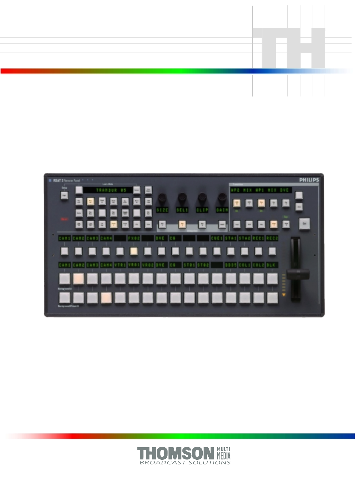
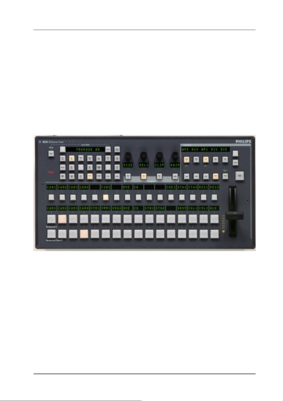
Fig. 1: RSAT2 Remote Control Panel
1.2 CONTROL AND DISPLAY ELEMENTS
3 x16 button source selection busses with 4 digit displays
Transition control field with fader
4x Digipots
4x Delegation buttons
Learn mode buttons with Display
2x Menu control buttons (Step up/down)
22 additionally programmable buttons
In learn mode only one function per button or digipot is programmable. Delegation
functions are not available. Also, functions of the display panel RPV are not recordable.
Operating Instructions - Rev. 1 / 11.2001
1
Page 7

Remote Control Panel RSAT11. General
The programmable memory of the RSAT2 is part of the DD35. Thus the programmed function set for the RSA T2 buttons can be switched from application to application. More complex button sequences can be achieved by programmed recall of
macro buttons of the DD35 main panel.
The standard unit is equipped with 1x reconfigurable 9 Pin D-Sub interface for connection to a host processor. Without further options the factory configuration is a
RS-422/485 port for direct connection to DD35’s panel controller.
2
Operating Instructions - Rev. 1 / 11.2001
Page 8

Remote Control Panel RSAT2 2. Technical Data
2. TECHNICAL DATA
Mechanics Width: 240 mm, Length: 464 mm, Depth: 115 mm
Weight: 5 kg
Desk cut out: 441 x 217 mm
Optional 19” Mounting frame
Voltage supply Line voltage: 100 V – 240 V $10 %, autosense
Line current: 0.8 A
Line frequency: 50 Hz to 60 Hz
Wide AC range power supply block
Power consumption: < 50 W
Environmental Operating temperature: +0° C ... 40° C
requirements Storage/transport temp: –40° C ... 85° C
Humidity: v95%, DIN IEC 68-2-14
non-condensing
Electromagnetic EMA: EN 55103-1, EN 55 022, Class B,
compability ESD: EN 61000-4-2
EMI: EN 61000-4-3
Burst: EN 61000-4-4 , IEC 1000-4-4
RF immunity: EN 61000-4-6
Safety VDE 0805, EN 60 950
Interface RS-422/485 port for direct connection to the DD35 panel controller.
9pin D-sub, female. Port re-configurable for RS-232.
Communication is asynchron with 38.4 kbaud, 1 start, 8 data, no parity, 1 stop bit.A factory re-configuration is recommended for use of an RSAT2 with a PC.
Standard Accessories Accessory pack with tools fuses and button spare parts.
Options 19” Mounting frame für rack mounting.
Order no.: RC 2326, 000 351 762 600
Operating Instructions - Rev. 1 / 11.2001
3
Page 9

Remote Control Panel RSAT22. Technical Data
4
Operating Instructions - Rev. 1 / 11.2001
Page 10

Remote Control Panel RSAT2 3. Installation and Startup
3. INSTALLATION AND STARTUP
3.1 SAFETY INSTRUCTIONS
Caution!
These instructions are for use by qualified personnel only. T o reduce the risk
of electric shock, do not perform any installation other than that contained in
the Operating Instructions unless you are qualified to do so.
Refer all servicing to qualified service personnel.
Attention!
Electrostatic sensitive devices on the p. c. boards. Observe the following
precaution for handling:
Handling or mounting the RSAT2 unit call for special attention to personal
safety. Personnel should be connected to ground potential via a wristlet (e.g.
3M Wristlet Serial 2200).
Do not touch the p. c. boards during mounting.
Repair the p. c. boards only at static-safe work stations.
Use antistatical protective bags when carrying the p.c. boards.
Operating Instructions - Rev. 1 / 11.2001
5
Page 11
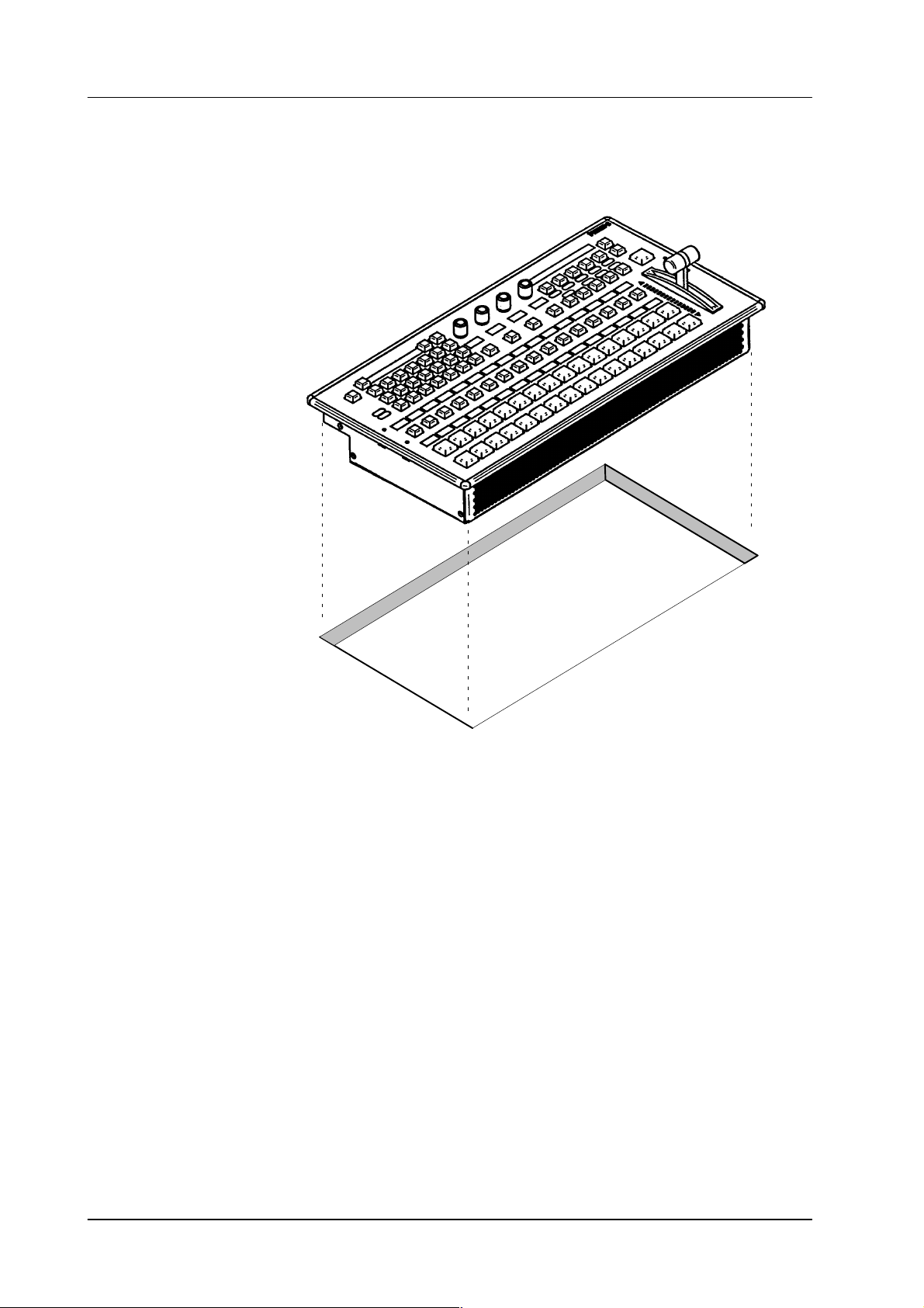
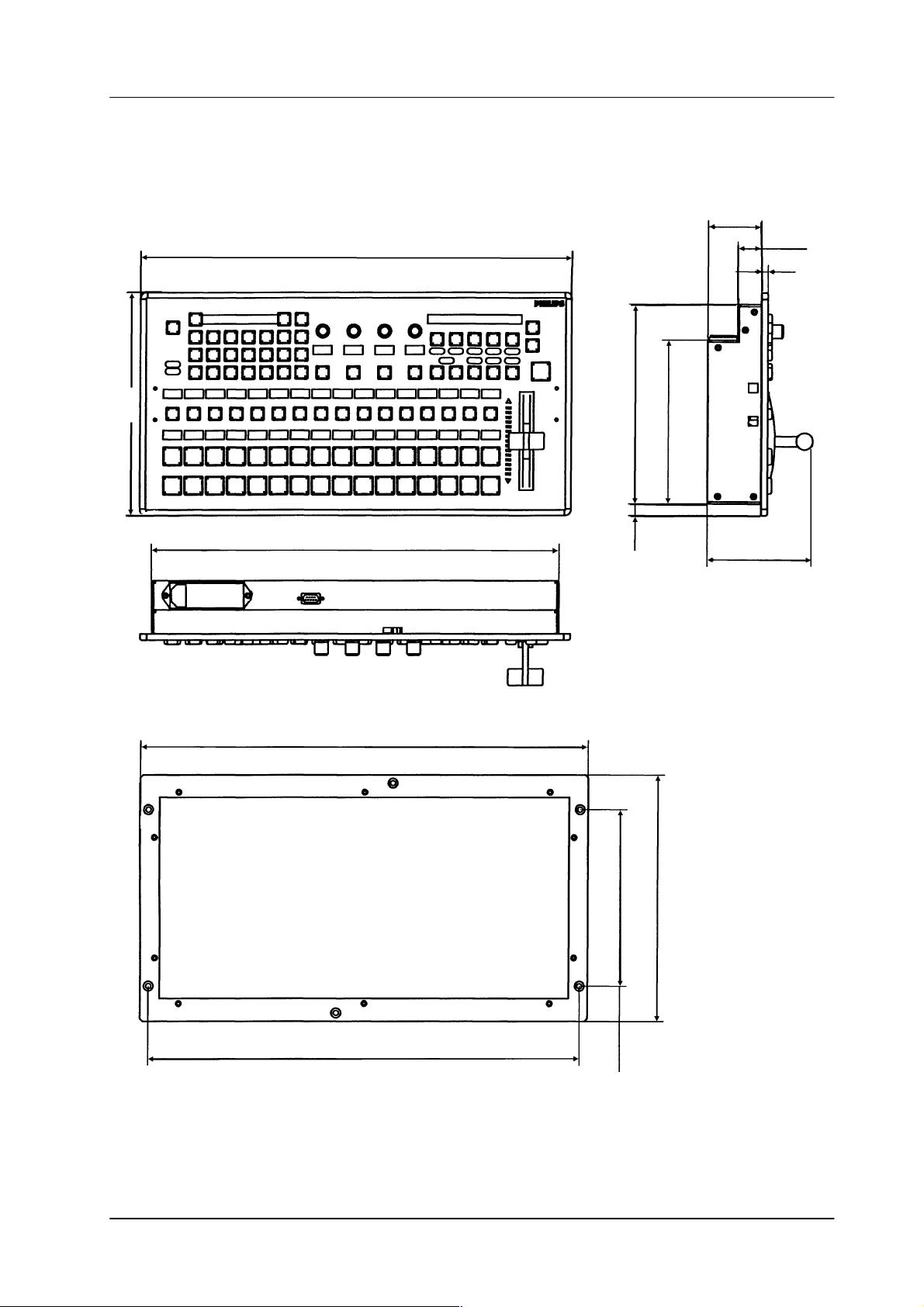
3.2 DESK MOUNTING
Remote Control Panel RSAT23. Installation and Startup
Cut-out dimensions: 441 x 217 mm
Fig. 2: Panel cut out
Unpack th e R S AT2 panel and remove the panel module from the mounting box.
The locking mechanism can be removed by the two release tools delivered in
the accessory pack. Therefore the module can be removed very simply.
Disconnect the cables.
Cut-out the openings in the desk.
Put in the mounting box of the panel. For fastening, bores are provided in the
frame. The housing can be fastened with countersunk wood screws with a diameter of 4 mm. The length of the screw depends on the plate thickness of the
desk. A set with mounting parts is included in the delivery of the panel.
Connect the cables into the corresponding plugs of the modules.
Put in the panel module in in the mounting box. By pressing, the modules enga-
ges independently. After mounting the panels please close all locking holes
witch the plastic caps delivered in the accessory pack.
6
Operating Instructions - Rev. 1 / 11.2001
Page 12
Remote Control Panel RSAT2 3. Installation and Startup
58
464
25.8
7
240
176.7
439
482.6
19” Mounting Frame
12.5 215
190.5
114.5
265.9
6 Rack units
465.1
Fig. 3: Mechanicak dimensions
Operating Instructions - Rev. 1 / 11.2001
All dimensions are [ mm ]
7
Page 13
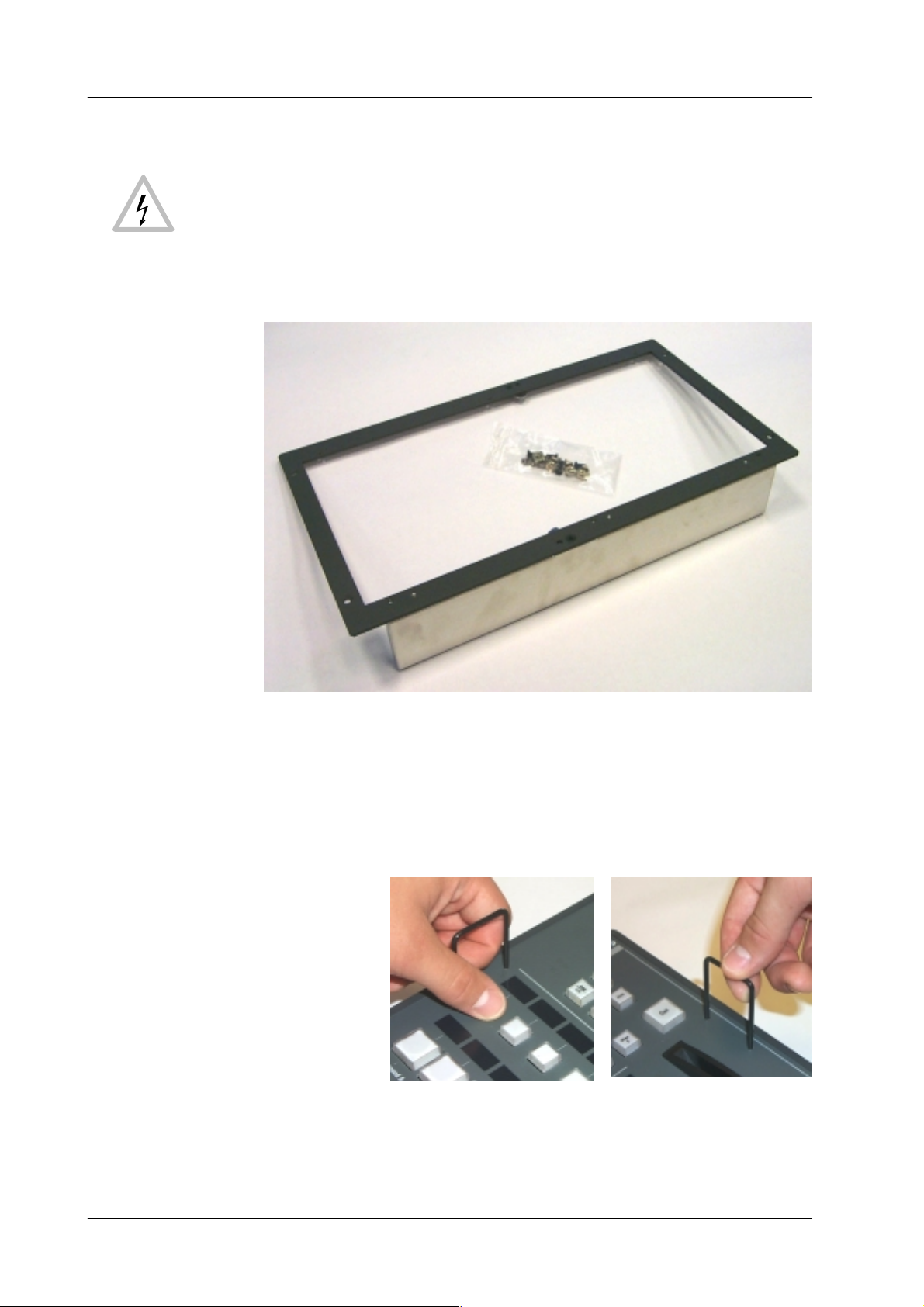
3.3 RACK MOUNTING
Caution:
Mounting the RSAT panel has only be done by qualified service personnel
being informed about the dangers involved!
Remote Control Panel RSAT23. Installation and Startup
Fig. 4: 19” mounting frame for RSAT2 remote control panel with mounting accessories
Mounting the 19” frame:
Mount the 19” frame into the rack by useing the deliverd accessories
Demount the RSAT2 module by useing the two release tools
(see figures below).
Fig. 5: Release tools
Disconnect control, DC and the ground cable.
8
Operating Instructions - Rev. 1 / 11.2001
Page 14
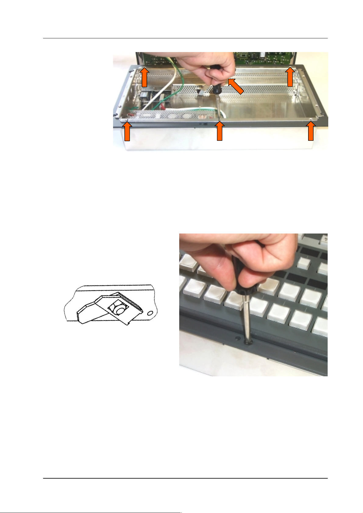
Remote Control Panel RSAT2 3. Installation and Startup
Fig. 6: Mounting the RSAT2 case
Put in the RSA T2 case into the 19” frame and fasten it with 6 screws (see acces-
sories).
Connect the cable and put in the RSAT2 module in the case. By pressing, the
module engages independently.
After mounting, please secure the modules with the two locking screws (see
figure below).
Locking mechanism
Fig. 7: Locking the RSAT2 module
Operating Instructions - Rev. 1 / 11.2001
9
Page 15

3.4 CONNECTING TO THE DD35 CONTROL PANEL
Attention:
The EMC regulations require the use of properly shielded cables in the installation of the device or the system. Suitable cables can be ordered from
Philips Broadcast.
Remote Control Panel RSAT23. Installation and Startup
REMOTE
J1
REMOTE 50
Re
RS 422 CONTROL PANELRS 232 INTERFACE
J2A
PORT 3
PORT 1
PORT 2
Ω
J3A
J2A
PORT 4
J2B PORT 2
J3B
RS-422
Ports
RS-422 Cable
(Option)
J4A
J4B
MODEM J5B
J5AGPI/GPOPORT 1
WIPE SELECTION AUX SELECTION
J6 J7
Protective Earth
Part of the DD35
control panel rear
AC INFuses
Fig. 8: Power and control connectors
The panel have a PE terminal as protective earth on rear.
PE
10
Befor mounting the Satellite
Panel, switch to ON
Operating Instructions - Rev. 1 / 11.2001
Page 16

Remote Control Panel RSAT2 3. Installation and Startup
3.5 PORT RE-CONFIGURATION RS-422 / RS-232
In case the RSAT2 panel shall be used in connection with a PC, the port can be
configurated as RS-232. For this a RS-232 cable is nesseccary.
Demount the panel module.
Change the flat cable from RS-422/485 connector (right) to the RS-232 con-
nector (left).
Switch the port selection switch to the left position.
RS-232 connector
Port selection switch:
Left position: RS-232
Right position: RS-422/485.
Fig. 9: Changing the seriall part standard
RS-422/485 connector
Operating Instructions - Rev. 1 / 11.2001
11
Page 17

Remote Control Panel RSAT23. Installation and Startup
12
Operating Instructions - Rev. 1 / 11.2001
Page 18

Remote Control Panel RSAT2 4. Operation
4. OPERATION
4.1 HOW TO START THE REMOTE PANEL
To start the protocol for the panel use the sidepanel menu. Step into the Install /
Panel / Satpanel menu and select the port number and the type of the protocol.
Fig. 10: DD35 install menu
After that the signal light of the remote panel has to be out. If it so, the panel is alive.
But if you do not have a macro file in your appli_cp.ini file the satellite panel will
be without any function. To add now the filename into the appli_cp.ini use the file
transfer program FTP to get the current appli_cp.ini and insert at the
[SAT_PANEL] under
filename = ”....”
the filename of the macro including the whole path.
E.g. filename = ”/flash/satpanel/me3_crs.sat”.
After the modification of the appli_cp.ini copy the file via FTP back into the mixer.
Now you should see the new function on the satellite panel.
After each new boot the file will be started automatically.
Operating Instructions - Rev. 1 / 11.2001
13
Page 19

4.2 HOW TO LEARN A NEW FUNCTION
The learn mode is activated by pressing the two buttons left and right of the big (16
character) display simultaneously.
Press the buttons simulaneously
Remote Control Panel RSAT24. Operation
Fig. 11: Learn mode buttons
The message
learn mode is deactivated the same way as it is activated (by pressing the two but-
tons).
The message “Learning ...” will disappear then.
Es ist sinnvoll erst ein vorhandenes Macro zu laden und dann dieses mit Learn abzuändern! Im Learn–Mode ohne vorhandenes Macro steht die Delegation nicht zu
Verfügung. Delegation kann nicht gelernt werden!!Der Learn–Mode wird für die jeweils aktive Gruppe (Delegation) aufgerufen.Bei Learn–Mode in der Present–Tastenreihe wird die Program–Tastenreihe nicht automatisch mitgezogen, sondern
muß seperat gelernt werden!
4.2.1 Learning buttons
Alle Kreuzschienennamen wurden übernommen.
Wenn man Buttons ohne Display auf Buttons mit Display legt bleibt das Display
Ensure that you are in learn mode.
dunkel.
L e a r n i n g . . .
will appear in the display. The
14
Press the desired button on the panel and hold it down.
Press the desired button on the DD35 control panel and then release it.
Release the button on the control panel.
The successful learning will be indicated by a beep (not yet implemented on
the Satellite Panel).
Operating Instructions - Rev. 1 / 11.2001
Page 20

Remote Control Panel RSAT2 4. Operation
4.2.2 Learning digipots
Turn simultaneously two digipots, one on the panel, the other one on the control
panel.
Keep in mind that the space between the digipots on the panel is very narrow
so you probably might have turned more than one digipot (“fat fingers” problem)
and the result of the learning is not what you have expected (the last digipots
“wins”).
Die Diaplays der Digipots werden auch umgelegt.
4.2.3 Learning faders
Move simultaneously two faders, the one and only on the panel and one of the
5 faders of the control panel.
4.3 WHAT CAN BE LEARNED
Interactively all faders and digipots can be learned. As for the buttons, the delegation buttons (the key1, key2 .. buttons in the keyers groups, the second/third buttons in the xbars, the Me1Wipe1,.. DVE2 buttons in the wipe group, the 2nd/rot/
user buttons (also wipe group), the arrow buttons in mask and matte group and all
that kind of buttons can NOT be learned).
All other buttons can be.
Displays and underfloor lamps can only be learned by using a setup file.
Note:
Due to the fact that all the functions of the RSAT2 panel can be learned no button
inlays are supplied. They can be easily be made in a do-i-you-self fashion. Printing
on foil e.g. with a laser printer. Foil thickness max. 200 mm.
Operating Instructions - Rev. 1 / 11.2001
15
Page 21

4.4 LOADING AND SAVING SETUPS
Laden und Speichern erfolgt in Setup–Menü
Speichern: RSAT Save User
Löschen: RSAT Kill User
Ausführen: RSAT Macro User
Currently there is no menu on the SidePanel, so you have to enter some commands from the VxWorks shell.
This implies that you have a terminal connected to the control panel.
Setups are stored in /flash/satpanel (default setups) and in /appdisk/satpanel
(user interactively defined setups).
4.4.1 Loading Setup
SatPanelLoadLearned <complete_filename>
Remote Control Panel RSAT24. Operation
4.4.2 Saving Setup
Example: SatPanelLoadLearned “/flash/satpanel/mstrmemo.sat”
or SatPanelLoadLearned “/appdisk/satpanel/mysatpan.sat
Y ou have to be careful because you save only the new macro in the flash or
ramdisk, but you do not change the item in the APPLI-CP.INI file.
If you like to have the macro as the default macro you have to change the file
APPLI-CP.INI.
SatPanelSaveLearned <filename>, <headername>, <displaytext>
Example: SatPanelSaveLearned “mysatpan”, “my header”, “hello world”
<filename> is the base of the filename.
The (internal) resulting filename will be
/appdisk/satpanel/filename.sat
So any extensions to the filename (e.g. “.txt”) and any preceding
path are ignored.
<headername> is a text which appears in the file (as a comment, will later be used
by the SidePanel GUI for the setup choice list).
<displaytext> is the text which has to be written into the big 16-character
The last 2 parameters can be omitted, in that case the header name is an empty
string and the 16-character display is cleared.
4.4.3 Format of the setup files
16
display.
Operating Instructions - Rev. 1 / 11.2001
Page 22

Remote Control Panel RSAT2 4. Operation
The setup files are special text files, which can be “understood” by the VxWorks
shell interpreter. This means you can alternatively load setups by running them as
shell script (by typing < /flash/appdisk/mstrmemo.sat, for example).
But this is not recommended due to the long time it usually takes for interpreting
the scripts (so you better use the SatPanelLoadLearned command).
Available commands (public C-functions):
Command Parameters Description
SatPanelLearnButton satButtonID, cpButtonID,
cd, co, kw, level
SatPanelLernDigi satDigiID, cpDigiID, cd,
co,
kw, level
SatPanelLearnDisplay satDispID, cpDispID, cd,
co,
kw, level
SatPanelWriteDisplay satDisplayID, text writes a 4–character text directely into the
SatPanelSetLamp SatButtonID, state sets the state of a lamp, no matter wheter
SatPanelSetAllLamps state sets all lamps to one state
SatPanelWriteAllDisplays text writes a text into all diplays
SatPanelUnLernAll <none> clears the leaning table. After that,
SatPanelRefreshState <none> Reloads the lamp states and display con-
learns a button
learns a digipot
learns a display
display no matter wheter it is delegated or
not
the lamp is delegated or not. <state> can
be 0 or 1.
the satpanel is “stupid”.
tents from the control panel. The learned
items are NOT modified !
Operating Instructions - Rev. 1 / 11.2001
17
Page 23

Remote Control Panel RSAT24. Operation
18
Operating Instructions - Rev. 1 / 11.2001
Page 24

Remote Control Panel RSAT2 4. Operation
4.5 RSAT2 MACROS AND CONTROL PANEL M/E DELEGATION
When using the supplied exemplary makros, consider the following: the makros
have been programmed for the switcher type DD35-4. When using the makros for
the new switcher types DD35-2 and DD35-3 or in connection with the M/E delegation, pay a t t e n t i o n t o t h e a s s i g n m e n t o f t h e M/E designation of the makro to the physical M/E of the control panel.
The supplied RSAT makros only function as usual when being used in a DD35-4
system and when the M/E control fields of the control panel are delegated 1:1 in
relation to the mainframe.
Assignment table
RSAT makros controlling parts of an M/E, have M/E designations relating to the
physical M/Es of the control panel.
There is the following assignment:
DD35-4 DD35-3 DD35-2 RSAT Makros
Physical Control Panel M/E RSAT makros are fixed-assigned to a physical
M/E1 me1_crs.sat
M/E2 M/E2 me2_crs.sat
M/E3 M/E3 M/E3 me3_crs.sat
PP PP PP pp_crs.sat
M/E
The physical M/E of the control panel, however, can control any mainframe M/E.
In this case, an RSAT makro acts on that mainframe M/E which is just delegated
in the physical M/E of the control panel.
Panel M/E1 is delegated to mainframe M/E3RPS35–3:
Panel M/E1 is delegated to mainframe M/E2
Panel M/E2 is delegated to mainframe M/E3
This workaround is only possible with full equipped mainframe!
Subsequent loading of RSAT2 macros does no more influence control panel software stability.
Predefined macros got new names:
RSAT1 macro names are beginning with a ”1_”
RSAT2 macro names are beginning with a ”2_”.
RSAT1 Macros:
RSAT2 Macros:
Operating Instructions - Rev. 1 / 11.2001
19
Page 25

Remote Control Panel RSAT24. Operation
20
Operating Instructions - Rev. 1 / 11.2001
Page 26

Remote Control Panel RSAT2 4. Operation
Special button assignment
not assigned
2nd
fixed assignment
Fig. 12: Spezial button assignment
2nd
2nd
Cut
Auto
Cut Cut
Key1 Key2
Auto
Auto
Key1 Key2
Operating Instructions - Rev. 1 / 11.2001
21
Page 27

5. SETUP / TEST
Remot Control Panel RSAT25. Setup / Test
Button
B100
Fig. 13: Satrting Setup/Test mode
Starting the Setup / Test mode:
Button
B101
Button
B102
Simultaneously press the button B100+B101+B102 (see RSAT2–Layout).
Release the button B100 at least, but within 2,5 seconds.
The display shows:
SETUP / TESTS-MENU
The right top display shows the software version (e.g.)
V 1.1.0 24.05.2000
The Display Group 4 (D416) shows the menu items.To step from one menu
item to another, use the highlighted keys under the display with the arrows (Button 501 and 601). To step to the top menu item, use Home key (Button 500).
To select one item, use OK-key (Button 502). The menu items are:
Adjustment: Fader-Range
Adjustment: Key-Click On / Off
Adjustment: Low-Light-Brightness
Adjustment: Telegram-Delay
22
Test: RS232/485
Operating Instructions - Rev. 1 / 11.2001
Page 28

Remote Control Panel RSAT2 5. Setup / Test
T est: All Keys
T est: All Lamps
T est: All Displays
Exit Setup-/Test-Menu
The individual tests are self-explaining. The display requests the user to per-
form further operational steps.
With the menu item Exit Menu, the normal operation mode is recalled.
The menu–item “Telegram Delay” should be only used by the service personal
(factory setting: Poti Delay=70mSec, Fader–Delay=60mSec).
Operating Instructions - Rev. 1 / 11.2001
23
Page 29

6. ANNEX
6.1 CODES OF THE OPERATING ELEMENTS
Remot Control Panel RSAT26. Annex
Name Range
LED’s Lgxx (g=1...6, xx=00...24)
Buttons and
LED’s
Display Dgxx (g=1...5, xx=00...16)
DigiPot Pgxx (g=2, xx=00...03)
Fader Fgxx (g=0, xx=00)
Bgxx (g=0...6, xx=00...28)
24
Operating Instructions - Rev. 1 / 11.2001
Page 30

6.2 DEFAULT MACROS
6.2.1 2PP_32ML.SAT
6. AnnexRemot Control Panel RSAT2
Digit
Menu
Key
Over
Matte
Add
Lin
Key
Inv
Key
Bus
Lum
Lin
Mask
On
Chr
Key
Mask
Key
Key
Bus
Pattn
1
Key
PVW
Couple
Split
Pattn
2
Cursor
Left
Bord
On
Up
Cancel
Cut
Auto
Adjust
Right
FGD
Fade
Down
Chr
Sel
Enter
Auto
Key
1
Key
2
Key
3
MaKE
BGD
B
Loop
BGD
DVE
Limit
Set
Key
A
1
Mix
Wipe
Shift
Key
2
1
Key
3
Wipe
2
Limit
On
Cut
Operating Instructions - Rev. 1 / 11.2001
Cut
Auto
Cut
Key 1
Auto
Key 1
Cut
Key 2
Auto
Key 2
Shift
Shift
25
Page 31

6. Annex Remot Control Panel RSAT2
6.2.2 2PP_24ML.SAT
Digit
Menu
Key
Over
Matte
Add
Lin
Key
Inv
Key
Bus
Lum
Lin
Mask
On
Chr
Key
Mask
Key
Key
Bus
Pattn
1
Key
PVW
Couple
Split
Pattn
2
Cursor
Left
Bord
On
Up
Cancel
Cut
Auto
Adjust
Right
FGD
Fade
Down
Chr
Sel
Enter
Auto
Key
1
Key
2
Key
3
MaKE
BGD
B
Loop
BGD
DVE
Limit
Set
Key
A
1
Mix
2nd
Key
Wipe
1
3rd
Key
2
3
Wipe
2
Limit
On
Cut
26
Cut
Key 1
Auto
Key 1
Cut
Key 2
Auto
Key 2
Cut
Key 3
Auto
Key 3
2nd
2nd
3rd
3rd
Operating Instructions - Rev. 1 / 11.2001
Page 32

6.2.3 2M3_32ML.SAT
6. AnnexRemot Control Panel RSAT2
Digit
Menu
Key
Over
Matte
Add
Lin
Key
Inv
Key
Bus
Lum
Lin
Mask
On
Chr
Key
Mask
Key
Key
Bus
Pattn
1
Key
PVW
Couple
Split
Pattn
2
Cursor
Left
Bord
On
Up
Cancel
Cut
Auto
Adjust
Right
FGD
Fade
Down
Chr
Sel
Enter
Auto
Key
1
Key
2
Key
3
MaKE
BGD
B
Loop
BGD
DVE
Limit
Set
Key
A
1
Mix
Wipe
Shift
Key
2
1
Key
3
Wipe
2
Limit
On
Cut
Operating Instructions - Rev. 1 / 11.2001
Cut
Auto
Cut
Key 1
Auto
Key 1
Cut
Key 2
Auto
Key 2
Shift
Shift
27
Page 33

6. Annex Remot Control Panel RSAT2
6.2.4 2M3_24ML.SAT
Digit
Menu
Key
Over
Matte
Add
Lin
Key
Inv
Key
Bus
Lum
Lin
Mask
On
Chr
Key
Mask
Key
Key
Bus
Pattn
1
Key
PVW
Couple
Split
Pattn
2
Cursor
Left
Bord
On
Up
Cancel
Cut
Auto
Adjust
Right
FGD
Fade
Down
Chr
Sel
Enter
Auto
Key
1
Key
2
Key
3
MaKE
BGD
B
Loop
BGD
DVE
Limit
Set
Key
A
1
Mix
2nd
Wipe
3rd
Key
2
1
Key
3
Wipe
2
Limit
On
Cut
28
Cut
Key 1
Auto
Key 2
Cut
Key 2
Auto
Key 2
Cut
Key 3
Auto
Key 3
2nd
2nd
3rd
3rd
Operating Instructions - Rev. 1 / 11.2001
Page 34

6.2.5 2M2_32ML.SAT
6. AnnexRemot Control Panel RSAT2
Digit
Menu
Key
Over
Matte
Add
Lin
Key
Inv
Key
Bus
Lum
Lin
Mask
On
Chr
Key
Mask
Key
Key
Bus
Pattn
1
Key
PVW
Couple
Split
Pattn
2
Cursor
Left
Bord
On
Up
Cancel
Cut
Auto
Adjust
Right
FGD
Fade
Down
Chr
Sel
Enter
Auto
Key
1
Key
2
Key
3
MaKE
BGD
B
Loop
BGD
DVE
Limit
Set
Key
A
1
Mix
Wipe
Shift
Key
2
1
Key
3
Wipe
2
Limit
On
Cut
Operating Instructions - Rev. 1 / 11.2001
Cut
Auto
Cut
Key 1
Auto
Key 1
Cut
Key 2
Auto
Key 2
Shift
Shift
29
Page 35

6. Annex Remot Control Panel RSAT2
6.2.6 2M2_24ML.SAT
Digit
Menu
Key
Over
Matte
Add
Lin
Key
Inv
Key
Bus
Lum
Lin
Mask
On
Chr
Key
Mask
Key
Key
Bus
Pattn
1
Key
PVW
Couple
Split
Pattn
2
Cursor
Left
Bord
On
Up
Cancel
Cut
Auto
Adjust
Right
FGD
Fade
Down
Chr
Sel
Enter
Auto
Key
1
Key
2
Key
3
MaKE
BGD
B
Loop
BGD
DVE
Limit
Set
Key
A
1
Mix
Wipe
Shift
Key
2
1
Key
3
Wipe
2
Limit
On
Cut
30
Cut
Auto
Cut
Key 1
Auto
Key 1
Cut
Key 2
Auto
Key 2
Shift
Shift
Operating Instructions - Rev. 1 / 11.2001
Page 36

6.2.7 2M1_32ML.SAT
6. AnnexRemot Control Panel RSAT2
Digit
Menu
Key
Over
Matte
Add
Lin
Key
Inv
Key
Bus
Lum
Lin
Mask
On
Chr
Key
Mask
Key
Key
Bus
Pattn
1
Key
PVW
Couple
Split
Pattn
2
Cursor
Left
Bord
On
Up
Cancel
Cut
Auto
Adjust
Right
FGD
Fade
Down
Chr
Sel
Enter
Auto
Key
1
Key
2
Key
3
MaKE
BGD
B
Loop
BGD
DVE
Limit
Set
Key
A
1
Mix
Wipe
Shift
Key
2
1
Key
3
Wipe
2
Limit
On
Cut
Operating Instructions - Rev. 1 / 11.2001
Cut
Auto
Cut
Key 1
Auto
Key 1
Cut
Key 2
Auto
Key 2
Shift
Shift
31
Page 37

6. Annex Remot Control Panel RSAT2
6.2.8 2M1_24ML.SAT
Digit
Menu
Key
Over
Matte
Add
Lin
Key
Inv
Key
Bus
Lum
Lin
Mask
On
Chr
Key
Mask
Key
Key
Bus
Pattn
1
Key
PVW
Couple
Split
Pattn
2
Cursor
Left
Bord
On
Up
Cancel
Cut
Auto
Adjust
Right
FGD
Fade
Down
Chr
Sel
Enter
Auto
Key
1
Key
2
Key
3
MaKE
BGD
B
Loop
BGD
DVE
Limit
Set
Key
A
1
Mix
Wipe
Shift
Key
2
1
Key
3
Wipe
2
Limit
On
Cut
32
Cut
Auto
Cut
Key 1
Auto
Key 1
Cut
Key 2
Auto
Key 2
Shift
Shift
Operating Instructions - Rev. 1 / 11.2001
Page 38

6.2.9 2_PP_32.SAT
6. AnnexRemot Control Panel RSAT2
Digit
Key
Over
Matte
Add
Lin
Key
Inv
Key
Bus
Lum
Lin
Mask
On
Chr
Key
Mask
Key
Key
Bus
Pattn
1
Key
PVW
Couple
Split
Pattn
2
Cursor
Bord
On
Cut
Auto
Adjust
FGD
Fade
Chr
Sel
Auto
Key
1
Key
2
Key
3
MaKE
Shift
BGD
B
Loop
BGD
DVE
Limit
Set
Key
A
1
Mix
Key
Wipe
1
Key
2
3
Wipe
2
Limit
On
Cut
Operating Instructions - Rev. 1 / 11.2001
Shift
Shift
Cut
Auto
Cut
Key 1
Auto
Key 1
Cut
Key 2
Auto
Key 2
33
Page 39

6. Annex Remot Control Panel RSAT2
6.2.10 2_PP_24.SAT
Digit
Key
Over
Matte
Add
Lin
Key
Inv
Key
Bus
Lum
Lin
Mask
On
Chr
Key
Mask
Key
Key
Bus
Pattn
1
Key
PVW
Couple
Split
Pattn
2
Cursor
Bord
On
Cut
Auto
Adjust
FGD
Fade
Chr
Sel
Auto
Key
1
Key
2
Key
3
MaKE
Shift
BGD
B
Loop
BGD
DVE
Limit
Set
Key
A
1
Mix
Key
Wipe
1
Key
2
3
Wipe
2
Limit
On
Cut
34
Shift
Shift
Cut
Auto
Cut
Key 1
Auto
Key 1
Cut
Key 2
Auto
Key 2
Operating Instructions - Rev. 1 / 11.2001
Page 40

6.2.11 2_ME3_32.SAT
6. AnnexRemot Control Panel RSAT2
Digit
Key
Over
Matte
Add
Lin
Key
Inv
Key
Bus
Lum
Lin
Mask
On
Chr
Key
Mask
Key
Key
Bus
Pattn
1
Key
PVW
Couple
Split
Pattn
2
Cursor
Bord
On
Cut
Auto
Adjust
FGD
Fade
Chr
Sel
Auto
Key
1
Key
2
Key
3
MaKE
Shift
BGD
B
Loop
BGD
DVE
Limit
Set
Key
A
1
Mix
Key
Wipe
1
Key
2
3
Wipe
2
Limit
On
Cut
Operating Instructions - Rev. 1 / 11.2001
Shift
Shift
Cut
Auto
Cut
Key 1
Auto
Key 1
Cut
Key 2
Auto
Key 2
35
Page 41

6. Annex Remot Control Panel RSAT2
6.2.12 2_ME3_24.SAT
Digit
Key
Over
Matte
Add
Lin
Key
Inv
Key
Bus
Lum
Lin
Mask
On
Chr
Key
Mask
Key
Key
Bus
Pattn
1
Key
PVW
Couple
Split
Pattn
2
Cursor
Bord
On
Cut
Auto
Adjust
FGD
Fade
Chr
Sel
Auto
Key
1
Key
2
Key
3
MaKE
Shift
BGD
B
Loop
BGD
DVE
Limit
Set
Key
A
1
Mix
Key
Wipe
1
Key
2
3
Wipe
2
Limit
On
Cut
36
Shift
Shift
Cut
Auto
Cut
Key 1
Auto
Key 1
Cut
Key 2
Auto
Key 2
Operating Instructions - Rev. 1 / 11.2001
Page 42

6.2.13 2_ME2_32.SAT
6. AnnexRemot Control Panel RSAT2
Digit
Key
Over
Matte
Add
Lin
Key
Inv
Key
Bus
Lum
Lin
Mask
On
Chr
Key
Mask
Key
Key
Bus
Pattn
1
Key
PVW
Couple
Split
Pattn
2
Cursor
Bord
On
Cut
Auto
Adjust
FGD
Fade
Chr
Sel
Auto
Key
1
Key
2
Key
3
MaKE
Shift
BGD
B
Loop
BGD
DVE
Limit
Set
Key
A
1
Mix
Key
Wipe
1
Key
2
3
Wipe
2
Limit
On
Cut
Operating Instructions - Rev. 1 / 11.2001
Shift
Shift
Cut
Auto
Cut
Key 1
Auto
Key 1
Cut
Key 2
Auto
Key 2
37
Page 43

6. Annex Remot Control Panel RSAT2
6.2.14 2_ME2_24.SAT
Digit
Key
Over
Matte
Add
Lin
Key
Inv
Key
Bus
Lum
Lin
Mask
On
Chr
Key
Mask
Key
Key
Bus
Pattn
1
Key
PVW
Couple
Split
Pattn
2
Cursor
Bord
On
Cut
Auto
Adjust
FGD
Fade
Chr
Sel
Auto
Key
1
Key
2
Key
3
MaKE
Shift
BGD
B
Loop
BGD
DVE
Limit
Set
Key
A
1
Mix
Key
Wipe
1
Key
2
3
Wipe
2
Limit
On
Cut
38
Shift
Shift
Cut
Auto
Cut
Key 1
Auto
Key 1
Cut
Key 2
Auto
Key 2
Operating Instructions - Rev. 1 / 11.2001
Page 44

6.2.15 2_ME1_32.SAT
6. AnnexRemot Control Panel RSAT2
Digit
Key
Over
Matte
Add
Lin
Key
Inv
Key
Bus
Lum
Lin
Mask
On
Chr
Key
Mask
Key
Key
Bus
Pattn
1
Key
PVW
Couple
Split
Pattn
2
Cursor
Bord
On
Cut
Auto
Adjust
FGD
Fade
Chr
Sel
Auto
Key
1
Key
2
Key
3
MaKE
Shift
BGD
B
Loop
BGD
DVE
Limit
Set
Key
A
1
Mix
Key
Wipe
1
Key
2
3
Wipe
2
Limit
On
Cut
Operating Instructions - Rev. 1 / 11.2001
Shift
Shift
Cut
Auto
Cut
Key 1
Auto
Key 1
Cut
Key 2
Auto
Key 2
39
Page 45

6. Annex Remot Control Panel RSAT2
6.2.16 2_ME1_24.SAT
Digit
Key
Over
Matte
Add
Lin
Key
Inv
Key
Bus
Lum
Lin
Mask
On
Chr
Key
Mask
Key
Key
Bus
Pattn
1
Key
PVW
Couple
Split
Pattn
2
Cursor
Bord
On
Cut
Auto
Adjust
FGD
Fade
Chr
Sel
Auto
Key
1
Key
2
Key
3
MaKE
Shift
BGD
B
Loop
BGD
DVE
Limit
Set
Key
A
1
Mix
Key
Wipe
1
Key
2
3
Wipe
2
Limit
On
Cut
40
Shift
Shift
Cut
Auto
Cut
Key 1
Auto
Key 1
Cut
Key 2
Auto
Key 2
Operating Instructions - Rev. 1 / 11.2001
 Loading...