

Page 1
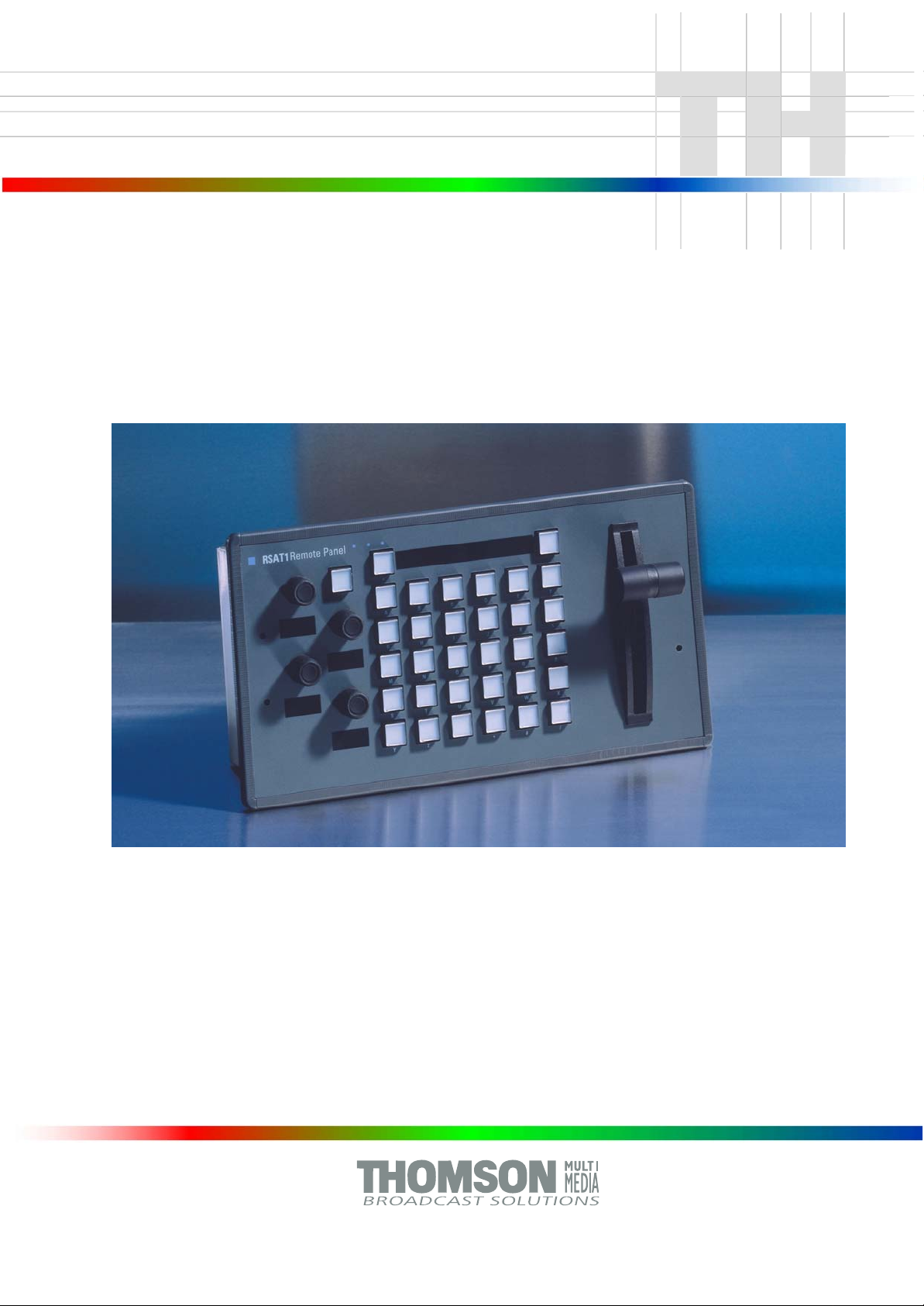
Remote Panel
RSAT1
Customer‘s Manual
Page 2

lished by
Pub
BTS Media Solutions GmbH
Brunnenweg 9
D-64331 Weiterstadt, Germany
P.O. Box 1165
Tel: +49 (0) 6155-870-0
Fax: +49 (0) 6155-870-300
Web Sites
Internet: www.thomsonbroadcast.com
www.imagingsystems.de
Intranet: www.weiterstadt.thmulti.com
Trademarks
All product names mentioned in this manual are the trademarks of their respective owners.
Copyrights
Information in this document is subject to change without notice.
This document and any updates and/or supplemental information, including any copies thereof, cannot be reproduced, neither
communicated to a third party, without written authorization from THOMSON multimedia Broadcast Solutions.
Please notify THOMSON multimedia Broadcast Solutions of any errors in this document. We also would appreciate any comments
you have to improve this manual.
BTS Media Solutions GmbH 2002. All rights reserved.
Page 3
Revision Report
Customer’s ManualSatellite Panel RSAT1
Documentation Order Number
RU 0061, 000 351 762 000
Before reading the entire
manual, please check for any
supplements at the end
of the manual.
Item Rev Date Serial
No
1 0 02.99 100 All Customer’s
2 1 12.99 Section 5 Corrections
3 2 02.2000 Section 4 Important Note
4 3 07.2002 Section 7 Default Macros
Pages
affected
Volume/Contents Remarks
First Issue
Manual
Page 4

Satellite Panel RSAT1
CONTENTS
Contents
Page
Revision Report
1. General 1
1.1 Application examples 1
1.2 Control and display elements 1
1.3 Options (initial order only) 3
1.4 Further options 3
2. Technical Date 5
3. Installation and Start-up 7
3.2 Mounting the Satellite Panel 8
3.3 Connecting to the DD35 control panel 9
3.4 Re-mounting the connectors to the botton 10
3.5 Port re-configuration RS-422 / RS-232 11
4. Operation 13
4.1 How to start the Satellite Panel 13
4.2 How to learn a new function 14
4.3 What can be learned 15
4.4 Loading and saving setups 16
4.5 Important note 18
5. Setup / Tests 21
6. Annex 23
7. Default Macros 33
Operating Instructions - Rev. 3 / 7.2002
I
Page 5

Contents
Satellite Panel RSAT1
II
Operating Instructions - Rev. 3 / 7.2002
Page 6
Satellite Panel RSAT1 1. General
1. GENERAL
The remote control panel RSAT1 is used for copying button functions of the DD35
main operation panels for control of mixer functions from another workplace.
Connected to DD35 main panel via RS-422 cable which can be ordered optionally.
Besides single button functions also the built in Digipots as well as the optional Fader can be trained with functions of the DD35 main panel – when the learn mode
is applied.
1.1 APPLICATION EXAMPLES
Remote control on source selection, effects register recall, transitions, macros,
Shot-Box, Keyer adjust ...., specifically in conjunction with the use of an additional
sidepanel control PC.
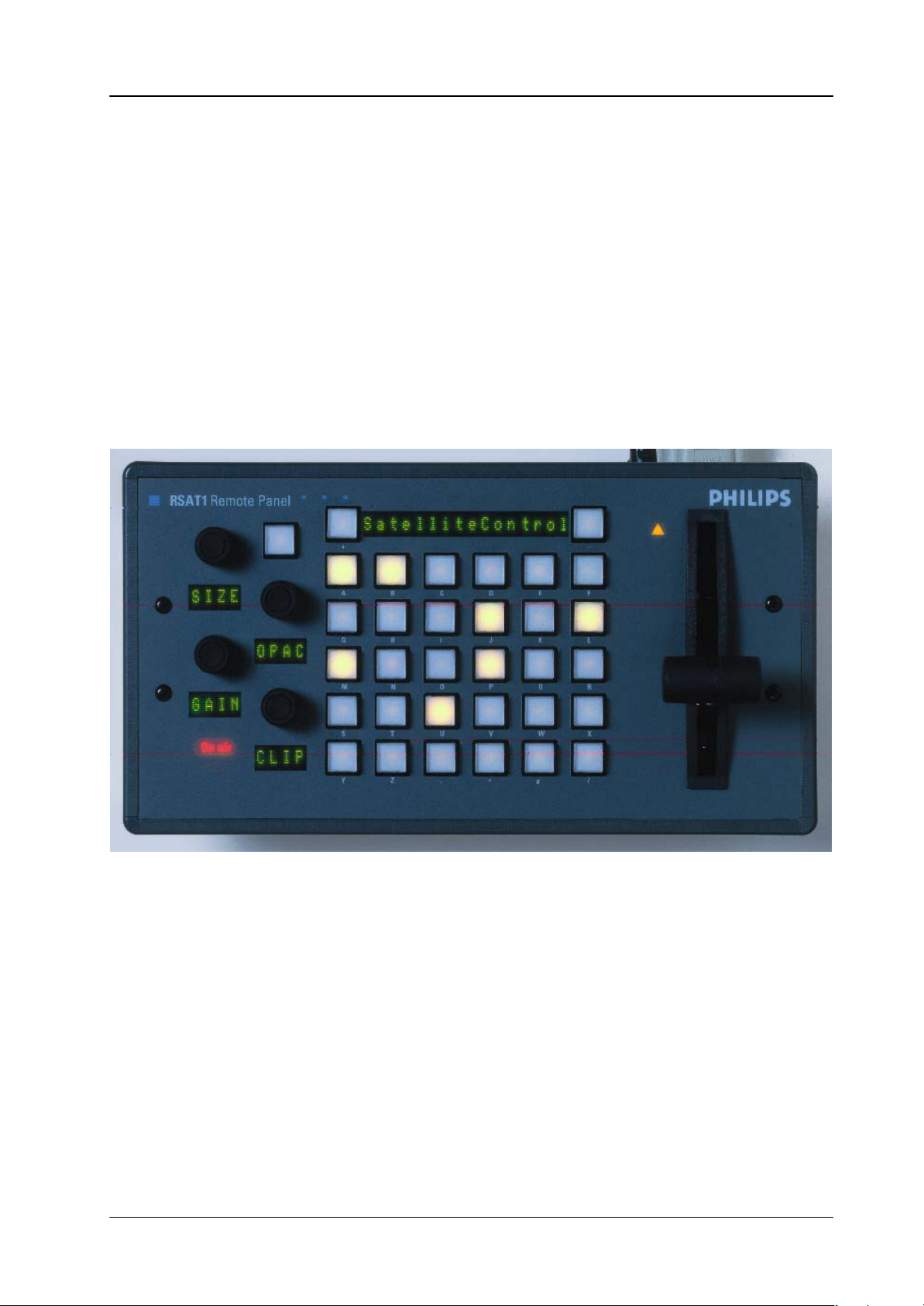
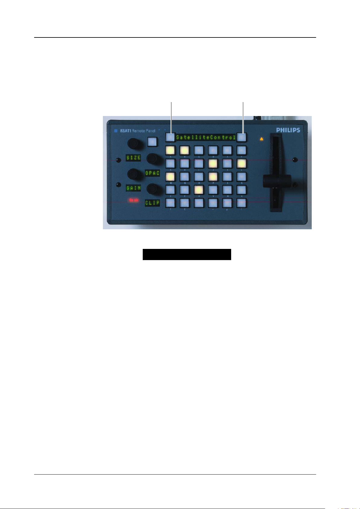
1.2 CONTROL AND DISPLAY ELEMENTS
4x Digipots
6x5 Button matrix with LEDs, programmable
2x Menu control buttons (Step up/down)
1x Display mode button (Name<––>Value)
16 Character menu function LEDs
4x4 Character LEDs (i.e. 1x per Digipot)
Serial connection status display
Operating Instructions - Rev. 3 / 7.2002
1
Page 7

Satellite Panel RSAT11. General
In learn mode only one function per button or digipot is programmable. Delegation
functions are not available. Also, functions of the display panel RPV are not recordable (at this time).
The programmable memory of the RSAT1 is part of the DD35. Thus the programmed function set for the RSAT1 buttons can be switched from application to application. More complex button sequences can be achieved by programmed recall of
macro buttons of the DD35 main panel.
The standard unit is equipped with 1x reconfigurable 9 Pin D-Sub interface for connection to a host processor. Without further options the factory configuration is a
RS-422/485 port for direct connection to DD35’s panel controller.
Without further option RC 2309, serial port and DC inlet connectors are mounted
on the rear side of the panel (not bottom!).
Power supply via separate Power Supply unit necessary (e.g. Option RC 2313).
RSAT1 panel with power supply, cable, gender changer and mounting tools.
2
Operating Instructions - Rev. 3 / 7.2002
Page 8

Satellite Panel RSAT1 1. General
1.3 OPTIONS (INITIAL ORDER ONLY)
RC 2303
0 351 760 300
RC 2309
0 351 760 900
RC 2311
0 351 761 100
Fader Lever (T -Bar, factory configured). For remote control on fader functions (e.g.
Timeline-, Transition- or DVE- sequence control) it is recommended to have a Fader module built–in at the factory. Fader functions learnable.
Bottom side connectors (DC & 9 pin). In case the RSAT1 panel shall be used in a
rack environment we recommend this basic factory re-configuration. DC and serial
9 pin connectors are on the bottom. Also DIY configurable at a later date.
Port re-configuration for RS-232 interface. A factory reconfiguration as RS-232
port is recommended for use of an RSAT1 with a PC etc. (initial option is free of
charge). The flexible concept would allow for usage in other applications (commands not yet supported by DD35 system).
1.4 FURTHER OPTIONS
RC 2310
0 351 761 000
RC 2312
0 351 761 200
RS-422 cable for standard configuration, 6m
Standard RS422 cable recommended for connection of RSA T1 to a RPD35 main
control panel. Not part of basic RSAT1 unit.
RS-232 cable (for re-configured port), 6 m
RC 2313
0 351 761 300
Ext. Power Supply block (with Euro plug)
Wide AC range power supply block (90 – 264V, ca.15W).
Plug-In Adaptors for USA, UK, Australia are included.
Operating Instructions - Rev. 3 / 7.2002
3
Page 9

Satellite Panel RSAT11. General
4
Operating Instructions - Rev. 3 / 7.2002
Page 10

Satellite Panel RSAT1 2. Technical Data
2. TECHNICAL DATA
Mechanics Width: 143 mm, Length: 270 mm, Depht: 72 mm
Weight: 0.5 kg
Desk cut out: 245 x 118 mm
Voltage supply DC IN voltage: +9 ... +24 V DC
Line current: 1.2 A max
Power consumption: < 15 W
Connector type: DIN 45318
Power supply via optional power supply unit RC2313.
Wide AC range power supply block (100 V – 240 V, 15W)
Plug-in adapter for US, UK and Australia are included.
Environmental Operating temperature: +0° C ... 40° C
requirements Storage/transport temp: –40° C ... 85° C
Humidity: v95%, DIN IEC 68-2-14
non-condensing
Electromagnetic EMA: EN 55103-1, EN 55 022, Class B,
compability ESD: EN 61000-4-2
EMI: EN 61000-4-3
Burst: EN 61000-4-4 , IEC 1000-4-4
RF immunity: EN 61000-4-6
Safety VDE 0805, EN 60 950
Interface RS-422/485 port for direct connection to the DD35 panel controller.
9pin D-sub, female. Port re-configurable for RS-232.
Communication is asynchron with 9600 baud, 1 start, 8 date, no parity , 1 stop bit.A factory re-configuration is recommended for use of an RSAT1 with a PC.
Operating Instructions - Rev. 3 / 7.2002
5
Page 11

Satellite Panel RSAT12. Technical Data
6
Operating Instructions - Rev. 3 / 7.2002
Page 12
Satellite Panel RSAT1 3. Installation and Startup
3. INSTALLATION AND STARTUP
3.1 SAFETY INSTRUCTIONS
Caution!
These instructions are for use by qualified personnel only. T o reduce the risk
of electric shock, do not perform any installation other than that contained in
the Operating Instructions unless you are qualified to do so. Refer all servicing to qualified service personnel.
Attention!
Electrostatic sensitive devices on the p. c. boards. Observe the following
precaution for handling:
Handling or mounting the RSAT1 unit call for special attention to personal
safety. Personnel should be connected to ground potential via a wristlet (e.g.
3M Wristlet Serial 2200).
Do not touch the p. c. boards during mounting.
Repair the p. c. boards only at static-safe work stations.
Use antistatical protective bags when carrying the p.c. boards.
Operating Instructions - Rev. 3 / 7.2002
7
Page 13
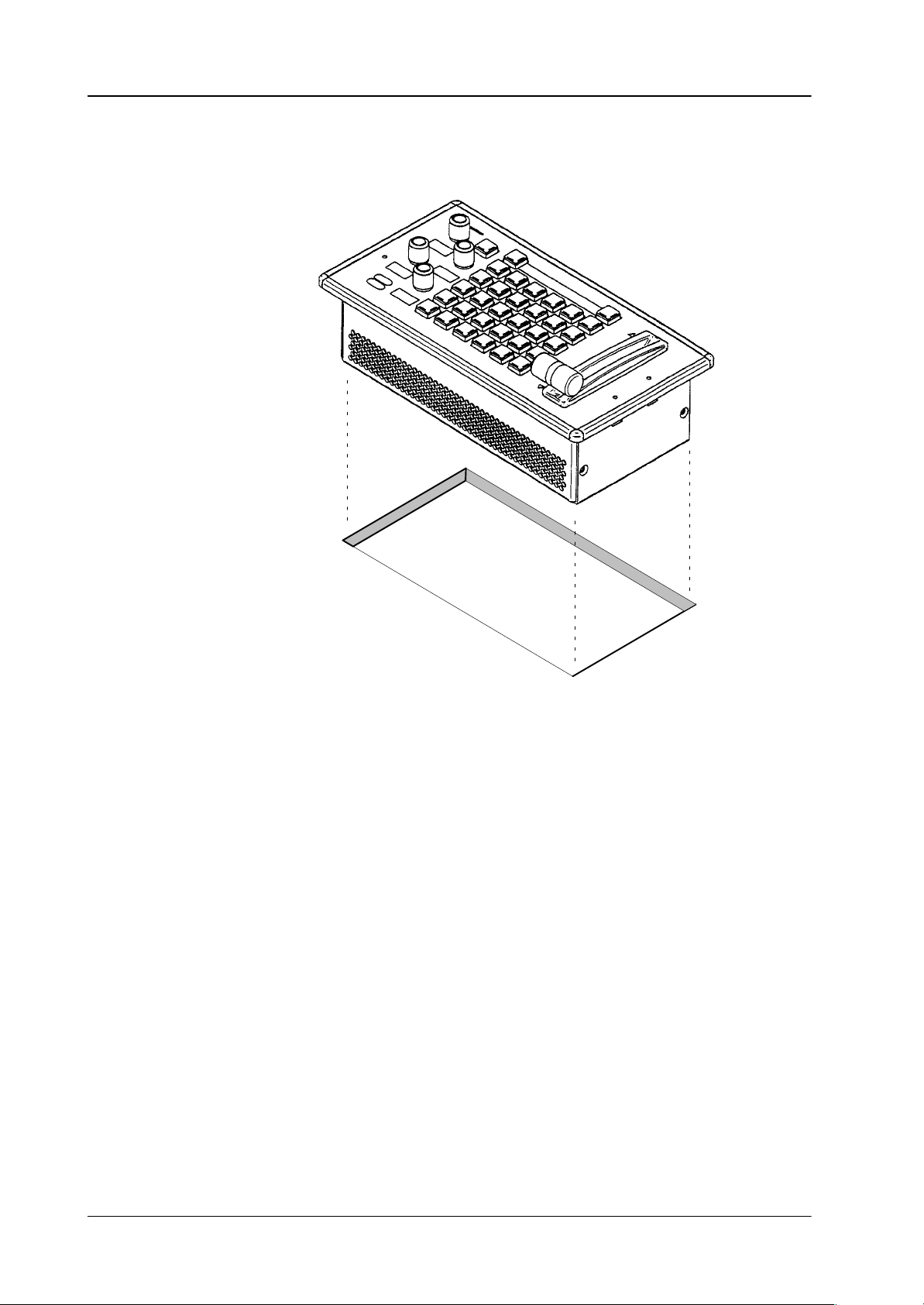
3.2 MOUNTING THE RSAT1 PANEL
Satellite Panel RSAT13. Installation and Startup
Cut-out dimensions: 245 x 118 mm
Unpack the RSAT1 panel and remove the panel module from the mounting box.
The locking mechanism can be removed by the two release tools delivered in
the accessory pack. Therefore the module can be removed very simply.
Disconnect the cables.
Cut-out the openings in the desk.
Put in the mounting box of the panel. For fastening, bores are provided in the
frame. The housing can be fastened with countersunk wood screws with a diameter of 4 mm. The length of the screw depends on the plate thickness of the
desk. A set with mounting parts is included in the delivery of the panel.
Connect the flat cables and the DC cables into the corresponding plugs of the
modules.
Put in the panel module in in the mounting box. By pressing, the modules enga-
ges independently. After mounting the panels please close all locking holes
witch the plastic caps delivered in the accessory pack.
8
Operating Instructions - Rev. 3 / 7.2002
Page 14
Satellite Panel RSAT1 3. Installation and Startup
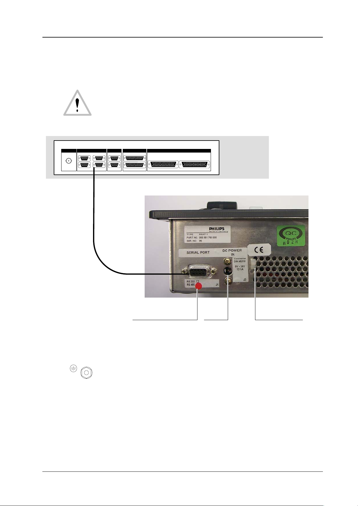
3.3 CONNECTING TO THE DD35 CONTROL PANEL
Attention:
The EMC regulations require the use of properly shielded cables in the installation of the device or the system. Suitable cables can be ordered from
Philips Digital Video Systems.
REMOTE
J1
REMOTE 50
Re
RS 422 CONTROL PANELRS 232 INTERFACE
J2A
J2A
PORT 3
PORT 1
Ω
PORT 2
J3A
PORT 4
J2B PORT 2
J3B
RS-422
Ports
RS-422 Cable
(Option)
J4A
J4B
MODEM J5B
J5AGPI/GPOPORT 1
WIPE SELECTION
J6 J7
Part of the DD35
control panel rear
AUX SELECTION
Marker for port configuration
Factory setting: RS-422/485
On the botton the panel have a PE terminal as protective earth.
PE
Operating Instructions - Rev. 3 / 7.2002
DC IN
any polarity
Fixture for DC cable
9
Page 15
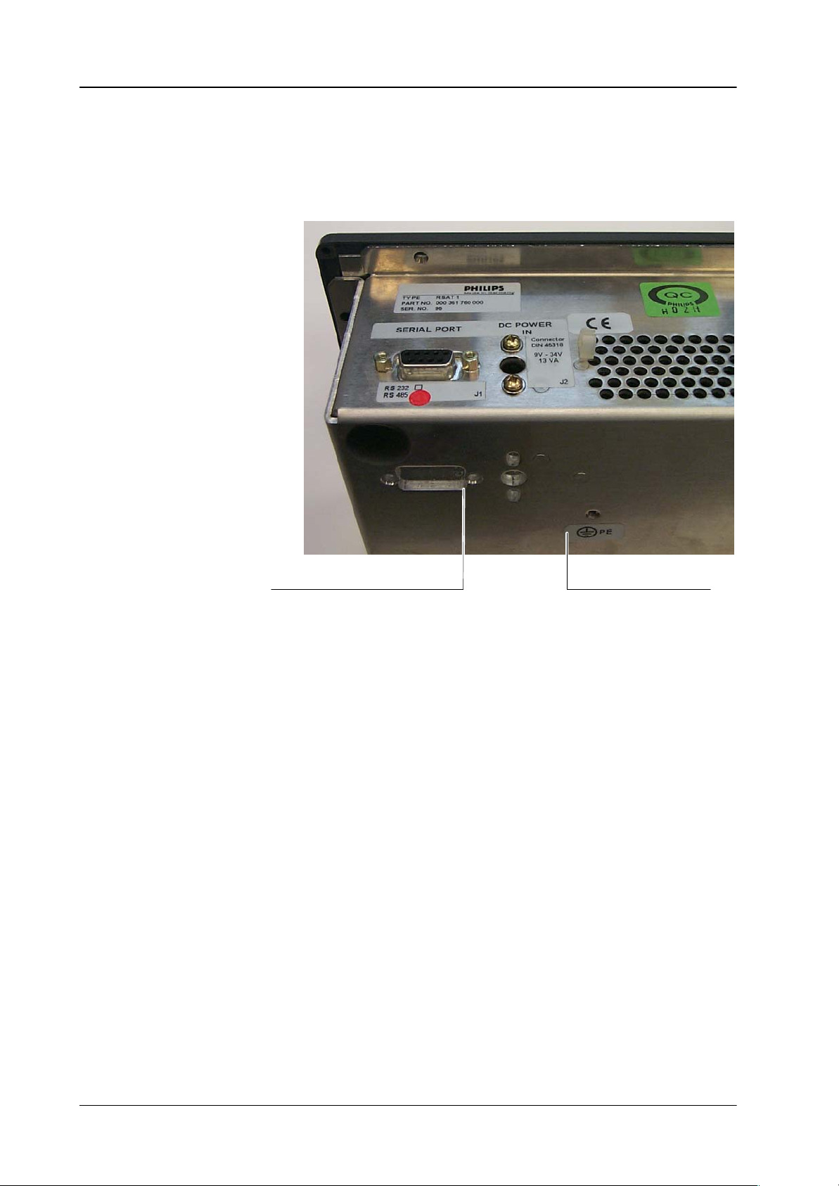
3.4 RE-MOUNTING THE CONNECTORS TO THE BOTTON
In case the RSAT1 panel shall be used in a rack environment, the connectores can
be moved easy the botton side:
Satellite Panel RSAT13. Installation and Startup
Remount the connector to the botton.
Protective earth terminal PE
10
Operating Instructions - Rev. 3 / 7.2002
Page 16
Satellite Panel RSAT1 3. Installation and Startup
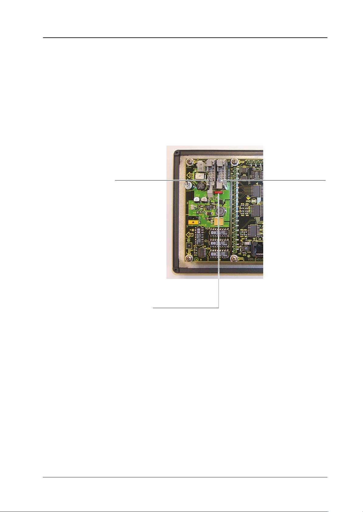
3.5 PORT RE-CONFIGURATION RS-422 / RS-232
In case the RSAT1 panel shall be used in connection with a PC, the port can be
configurated as RS-232. For this a RS-232 cable is nesseccary.
Demount the panel module.
Change the flat cable from RS-422/485 connector (right) to the RS-232 con-
nector (left).
Switch the port selection switch to the left position.
RS-232 connector
RS-422/485 connector
Port selection switch:
Left position: RS-232
Right position: RS-422/485.
Operating Instructions - Rev. 3 / 7.2002
11
Page 17

Satellite Panel RSAT13. Installation and Startup
12
Operating Instructions - Rev. 3 / 7.2002
Page 18
Satellite Panel RSAT1 4. Operation
4. OPERATION
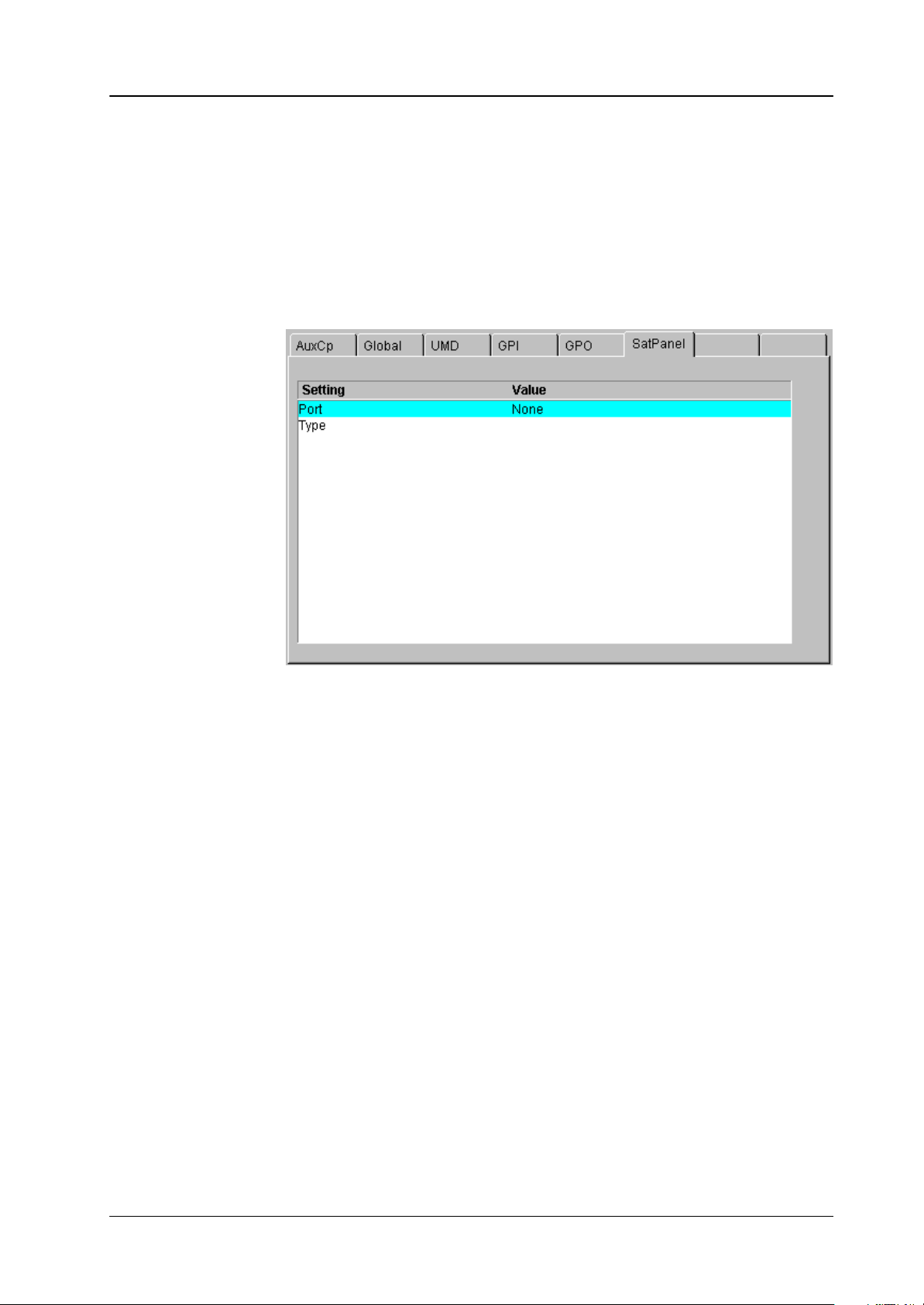
4.1 HOW TO START THE SATELLITE PANEL
To start the protocol for the satellite panel use the sidepanel menu. Step into the
install / panel / satpanel menu and select the port number and the type (satpanel)
of the protocol.
After that the signal light of the satellite panel has to be out. If it so, the Satellite
Panel is alive. But if you do not have a macro file in your appli_cp.ini file the satellite
panel will be without any function. To add now the filename into the appli_cp.ini
use the file transfer program FTP to get the current appli_cp.ini and insert at the
[SAT_PANEL] under
filename = ”....”
the filename of the macro including the whole path.
E.g. filename = ”/flash/satpanel/me3key1.sat”.
After the modification of the appli_cp.ini copy the file via FTP back into the mixer.
Now you should see the new function on the satellite panel.
After each new boot the file will be started automatically.
Operating Instructions - Rev. 3 / 7.2002
13
Page 19
4.2 HOW TO LEARN A NEW FUNCTION
The learn mode is activated by pressing the two buttons left and right of the big (16
character) display simultaneously.
Press the buttons simulaneously
Satellite Panel RSAT14. Operation
The message
learn mode is deactivated the same way as it is activated (by pressing the two but-
tons).
The message “Learning ...” will disappear then.
4.2.1 Learning buttons
Ensure that you are in learn mode.
Press the desired button on the Satellite Panel and hold it down.
Press the desired button on the DD35 control panel and then release it.
The successful learning will be indicated by a beep (not yet implemented on
L e a r n i n g . . .
Release the button on the control panel.
the Satellite Panel).
will appear in the display. The
14
Operating Instructions - Rev. 3 / 7.2002
Page 20

Satellite Panel RSAT1 4. Operation
4.2.2 Learning digipots
Turn simultaneously two digipots, one on the Satellite Panel, the other one on
the control panel.
Keep in mind that the space between the digipots on the Satellite Panel is very
narrow so you probably might have turned more than one digipot (“fat fingers”
problem) and the result of the learning is not what you have expected (the last
digipots “wins”).
4.2.3 Learning faders
Move simultaneously two faders, the one and only on the Satellite Panel and
one of the 5 faders of the control panel.
4.3 WHAT CAN BE LEARNED
Interactively all fade r s and digipots can be learned. As for the buttons, the delegation buttons (the key1, key2 .. buttons in the keyers groups, the second/third buttons in the xbars, the Me1Wipe1,.. DVE2 buttons in the wipe group, the 2nd/rot/
user buttons (also wipe group), the arrow buttons in mask and matte group and all
that kind of buttons can
All other buttons can be.
Displays and underfloor lamps can only be learned by using a setup file.
Note:
Due to the fact that all the functions of the RSAT1 panel can be learned no button
inlays are supplied. They can be easily be made in a do-i-you-self fashion. Printing
on foil e.g. with a laser printer. Foil thickness max. 200 mm.
NOT be learned).
Operating Instructions - Rev. 3 / 7.2002
15
Page 21

4.4 LOADING AND SAVING SETUPS
Currently there is no menu on the SidePanel, so you have to enter some commands from the VxWorks shell.
This implies that you have a terminal connected to the control panel.
Setups are stored in /flash/satpanel (default setups) and in /appdisk/satpanel
(user interactively defined setups).
4.4.1 Loading Setup
SatPanelLoadLearned <complete_filename>
Example: SatPanelLoadLearned “/flash/satpanel/mstrmemo.sat”
or SatPanelLoadLearned “/appdisk/satpanel/mysatpan.sat
Y ou have to be careful because you save only the new macro in the flash or
ramdisk, but you do not change the item in the APPLI-CP.INI file.
If you like to have the macro as the default macro you have to change the file
APPLI-CP.INI.
Satellite Panel RSAT14. Operation
4.4.2 Saving Setup
SatPanelSaveLearned <filename>, <headername>, <displaytext>
Example: SatPanelSaveLearned “mysatpan”, “my header”, “hello world”
<filename> is the base of the filename.
<headername> is a text which appears in the file (as a comment, will later be used
<displaytext> is the text which has to be written into the big 16-character
The last 2 parameters can be omitted, in that case the header name is an empty
string and the 16-character display is cleared.
4.4.3 Format of the setup files
The (internal) resulting filename will be
/appdisk/satpanel/filename.sat
So any extensions to the filename (e.g. “.txt”) and any preceding
path are ignored.
by the SidePanel GUI for the setup choice list).
display.
16
The setup files are special text files, which can be “understood” by the VxWorks
shell interpreter. This means you can alternatively load setups by running them as
shell script (by typing < /flash/appdisk/mstrmemo.sat, for example).
But this is not recommended due to the long time it usually takes for interpreting
the scripts (so you better use the SatPanelLoadLearned command).
Operating Instructions - Rev. 3 / 7.2002
Page 22

Satellite Panel RSAT1 4. Operation
Available commands (public C-functions):
Command Parameters Description
SatPanelLearnButton satButtonID, cpButtonID,
cd, co, kw, level
SatPanelLernDigi satDigiID, cpDigiID, cd,
co,
kw, level
SatPanelLearnDisplay satDispID, cpDispID, cd,
co,
kw, level
SatPanelWriteDisplay satDisplayID, text writes a 4–character text directely into the
SatPanelSetLamp SatButtonID, state sets the state of a lamp, no matter wheter
SatPanelSetAllLamps state sets all lamps to one state
SatPanelWriteAllDisplays text writes a text into all diplays
SatPanelUnLernAll <none> clears the leaning table. After that,
SatPanelRefreshState <none> Reloads the lamp states and display con-
learns a button
learns a digipot
learns a display
display no matter wheter it is delegated or
not
the lamp is delegated or not. <state> can
be 0 or 1.
the satpanel is “stupid”.
tents from the control panel. The learned
items are NOT modified !
Operating Instructions - Rev. 3 / 7.2002
17
Page 23

4.5 IMPORTAND NOTES
RSAT MAKROS and Control Panel M/E Delegation
When using the supplied exemplary makros, consider the following: the makros
have been programmed for the switcher type DD35-4. When using the makros for
the new switcher types DD35-2 and DD35-3 or in connection with the M/E delegation, pay attention to the assignment of the M/E designation of the makro to the physical M/E of the control panel.
The supplied RSAT makros only function as usual when being used in a DD35-4
system and when the M/E control fields of the control panel are delegated 1:1 in
relation to the mainframe.
Assignment table:
RSAT makros controlling parts of an M/E, have M/E designations relating to the
physical M/Es of the control panel.
There is the following assignment:
DD35-4 DD35-3 DD35-2 RSAT Makros
Satellite Panel RSAT14. Operation
Physical Control Panel M/E RSAT makros are fixed-assigned to a physical
M/E1 me1_key1.sat, me1_key2.sat, me1_key3.sat,
M/E2 M/E2 me2_key1.sat, me2_key2.sat, me2_key3.sat,
M/E3 M/E3 M/E3 me3_key1.sat, me3_key2.sat, me3_key3.sat,
PP PP PP pp_dsk1.sat, pp_dsk2.sat, pp_dsk3.sat,
M/E
me1_trns.sat, me1_memo.sat
me2_trns.sat, me2_memo.sat
me3_trns.sat, me3_memo.sat
pp_dsk4.sat, pp_dsk5.sat, pp_dsk6.sat,
pp_trns.sat, pp_memo.sat, mstrmemo.sat
The physical M/E of the control panel, however, can control any mainframe M/E.
In this case, an RSAT makro acts on that mainframe M/E which is just delegated
in the physical M/E of the control panel.
Examples:
DD35-4
Physical
Control Panel
M/E
M/E1 M/E2 M/E2 me1_key1.sat, me1_key2.sat, me1_key3.sat,
M/E2 M/E3 M/E3 me2_key1.sat, me2_key2.sat, me2_key3.sat,
M/E3 M/E1 M/E1 me3_key1.sat, me3_key2.sat, me3_key3.sat,
PP PP PP pp_dsk1.sat, pp_dsk2.sat, pp_dsk3.sat,
Delegated
Mainframe
M/E
RSAT
makros act in
mainframe
M/E
RSAT makros only run on a physical M/E
me1_trns.sat, me1_memo.sat
me2_trns.sat, me2_memo.sat
me3_trns.sat, me3_memo.sat
pp_dsk4.sat, pp_dsk5.sat, pp_dsk6.sat,
pp_trns.sat, pp_memo.sat, mstrmemo.sat
18
Operating Instructions - Rev. 3 / 7.2002
Page 24

Satellite Panel RSAT1 4. Operation
DD35-2
Physical
Control Panel
M/E
– – – me1_key1.sat, me1_key2.sat, me1_key3.sat,
– – – me2_key1.sat, me2_key2.sat, me2_key3.sat,
M/E3 PP PP me3_key1.sat, me3_key2.sat, me3_key3.sat,
PP M/E1 M/E1 pp_dsk1.sat, pp_dsk2.sat, pp_dsk3.sat,
Delegated
Mainframe
M/E
RSAT
makros act in
mainframe
M/E
RSAT makros only run on a physical M/E
me1_trns.sat, me1_memo.sat
me2_trns.sat, me2_memo.sat
me3_trns.sat, me3_memo.sat
pp_dsk4.sat, pp_dsk5.sat, pp_dsk6.sat,
pp_trns.sat, pp_memo.sat, mstrmemo.sat
Operating Instructions - Rev. 3 / 7.2002
19
Page 25

Satellite Panel RSAT14. Operation
20
Operating Instructions - Rev. 3 / 7.2002
Page 26

Satellite Panel RSAT1 5. Setup / Test
5. SETUP / TEST
3rd button
Starting the Setup / Test mode:
+ button
– button
Simultaneously press the button (3rd button without designation, see figure
above), the + button and – button.
release the button (without designation) at last.
The display shows:
SETUP / TESTS
The + button now enables to ciyclically select one of the following operational
modes:
Fader Adjust
Key Click
Low Light
Show SW Version
Test: Display
Test: Key
Operating Instructions - Rev. 3 / 7.2002
21
Page 27

Satellite Panel RSAT15. Setup / Test
Test: 232 / 485
Test: Lamps
Exit Menu
The – button starts the selected operational mode. The individual tests are self-
explaining. The display requests the user to perform further operational steps.
With menu item Exit Menu, the normal operation mode is recalled.
22
Operating Instructions - Rev. 3 / 7.2002
Page 28

Satellite Panel RSAT1 6. Annex
6. ANNEX
6.1 CODES OF THE OPERATING ELEMENTS
Name Range Telegram
LED Lxx (L00 ... L36) Lxx0 = off
Lxx1 = on
Lxx2 = all lamps off
Lxx3 = all lamps on
Button Bxx (B00 ... B32) Rxx = released
Pxx = pressed
Display Dxx (D00 ... D08) txx <max. 26 char>
tAD <text> send to all displays
DigiPot Pxx (P00 ... P03)
Fader Fxx (F00) Axxvvv (vvvv = 0000 ... 4095)
Dxxvvv (vvv= 999)
Operating Instructions - Rev. 3 / 7.2002
23
Page 29

6.2 SERIAL PROTOCOL FOR THE DD35 SATELLITE PANEL
6.2.1 PREFACE
This protocol describes a point-to-point serial protocol.
The intention is to provide a robust flexible means to hook up specialized hardware
with a standard PC. Inside the specialized hardware is an industry single chip microprocessor.
6.2.2 ELECTRICAL SPECIFICATIONS
This protocol uses a full-duplex RS-232 conformant serial line without hardware
handshake.
6.2.3 COMMUNICATION PARAMETERS
Satellite Panel RSAT16. Annex
Communication is asynchronous with 9600 Baud, 1 Start, 8 Data,
No parity, 1 Stop bit.
6.2.4 PROTOCOL DESCRIPTION
The datagram derived from the KERMIT packet format consists of
Start length type Data chksum end/cr lf
0x01 toascii(length) <type> ... char(chk) 0x0d 0x0a
Each protocol field – except the data field – is one ASCII byte. The Data field may
be longer.
Length is the count of all following bytes up to and including chksum.
Type is the message type described later. Type is a printable ASCII character.
Data depends on type and is described later together with the type. Data is printa-
ble ASCII character(s).
For calculation of chksum the following C program is given. A value of ‘~’ in this
field indicates that the checksum was not calculated.
24
Operating Instructions - Rev. 3 / 7.2002
Page 30

Satellite Panel RSAT1 6. Annex
The lf character is optional.
unsigned char chksum, chk;
int i;
chksum = toascii(length) + type;
for ( i = 0; i < (length – 2 ); i++)
{
chksum += data[i];
}
chk = chksum & 0x3F;
The function char() simply adds a space (0x20) to the number.
The function toascii() converts the number into the ascii character. The datagram
length is therefore restricted to 9 bytes. The new text (t) command makes it necessary to change the toascii() function. Allowed characters for the Length field are
now ’0’ .. ’9’ plus ’:’ .. ’~’ where a Lenght of ’:’ means 10 bytes and so on until ’~’
which means 78 bytes.
unsigned char toascii(size_t count)
{
unsigned char retval = ’0’;
if ( count <= (size_t) (’~’ – ’0’) )
{
retval += (unsigned char) count);
}
else
{
// error
}
return retval;
}
Operating Instructions - Rev. 3 / 7.2002
25
Page 31

Satellite Panel RSAT16. Annex
6.3 MESSAGE TYPES
Type Data Length Comment
? 2 Are You There ?
Y 2 Acknowledge.
N 2 Not Acknowledge. Last datagram was corrupted.
E <error string> 2+length(string) Error packet. String length max. = 767
Sent by sidepanel keyboard.
P NN 4 button Pressed. NN = 00 .. 99 the number of the button.
Sent by sidepanel keyboard
R NN 4 button Released. NN = 00 .. 99
Sent by sidepanel keyboard.
D NNVVV 7 Digipot increment. NN = 00 .. 99. VVV = –999 .. +999
Sent by sidepanel keyboard.
L NNV 5 Lamp on/off. NN = 00 .. 99. V = 0 (off), V = 1 (on),
V = 2 (all lamps off), V = 3 (all lamps on) (NN=don’t care)
sent by sidepanel PC.
initially all lamps will be off.
A NNVVVV 8 Absolute Value (e.g. generated from an A/D converter)
NN = 00.. 99 the number of value
VVVV = Absolute value 0000 ... 4095
sent by Satellite Panel
S 2 Status request for all absolute values
sent by sidepanel PC
! 2 Reset sidepanel keyboard
sent by sidepanel PC
H 2 Hold. sidepanel keyboard stops sending of messages.
sent by sidepanel PC
G 2 Go. sidepanel keyboard starts sending messages.
B VVV 5 Button Backlight Intensity.
VVV = 000 ... 100
000 = minimum backlight intensity
100 = maximum backlight intensity (100 %)
sent by sidepanel PC
T V 3 TFT Display Backlight
V = 0 (TFT Backlight OFF)
V = 1 (TFT Backlight ON)
sent by sidepanel PC
initially the TFT–Backlight is ON.
I VVV 5 TFT Display Intensity.
VVV = 000 ... 100
000 = minimum intensity
100 = maximum (100 %)
sent by sidepanel PC
26
Operating Instructions - Rev. 3 / 7.2002
Page 32

Satellite Panel RSAT1 6. Annex
Type Data Length Comment
t NN<text> 4 + length(text) text to be displayed in character displays
(not the TFT display!)
NN = (00..99) display number
NN == AD has a special meaning: it addresses all
displays in the device. (e.g. tADHello..)
<text> = any printable ASCII text. To keep the text
readable control characters (if needed) must be
prefixed with the backslash (\).
e.g. “\\” => print ’\’
“\r” => CR (set cursor to top of disp)
“\n” => LF (clear disp)
“\t” => TAB (move cursor to fixed TABs
4, 8, 12, 16)
“\vv => ASCII char as a Hex value (\00...\7F)
M NVVVV 7 (M)usic, activates beeper in the satellite panel.
N : 0 = normal beep, length of beep is
VVVV * 1mSec
1 = KeyClick on, length of click is
VVVV * 1mSec
2 = KeyClick off, VVVV has no meaning
l VVVVVVVVVV 12 (lower case L)
switch all LEDs at one time
V = 0...F switch four LED’s (hexdecimal coded 1,2,4,8)
VVVVVVVVVV
IIIIIIIII+ Lamp: 39–36 (max LED=37)
IIIIIIII+– Lamp: 35–32
IIIIIII+–– Lamp: 31–28
IIIIII+––– Lamp: 27–24
IIIII+–––– Lamp: 23–20
IIII+––––– Lamp: 19–16
III+–––––– Lamp: 15–12
II+––––––– Lamp: 11–08
I+–––––––– Lamp: 07–04
+––––––––– Lamp: 03–00 (L00=1,L01=2,L02=4.L03=8)
Operating Instructions - Rev. 3 / 7.2002
27
Page 33

6.4 COMMUNICATION GUIDELINES
Each side can initiate the communication by sending ‘?’ datagrams every two or
so seconds. When receiving ‘?’ the receiver ackknowledges with an Y datagram.
Each datagram – except Y,N,E – has to be acked within 30 milliseconds. Otherwise
it is re-transmitted after 0.5 seconds. After 5 consecutive re-transmissions it is assumed that the partner has been powered off. This should be indicated somehow
and the communication state goes to sending ‘?’. The communication breakdown
indication can be one of the following:
undersurface LED with an appropriate symbol like on the DD35 control panel
running light over all buttons (like CP-3xx series panels when not polled)
lighting all buttons.
Status Diagram
Satellite Panel RSAT16. Annex
Power-on
send ’?’
5 consecutive timeouts
IDLE
Valid command received
CONNECT
Process main loop
28
Operating Instructions - Rev. 3 / 7.2002
Page 34

Satellite Panel RSAT1 6. Annex
6.5 SIDEPANEL KEYBOARD SOFTWARE GUIDELINES
In CONNECT state the sidepanel keyboard processes the incoming command,
scans its hardware, sends the command for the changed button or digipot – if
not quieted by the HOLD command.
The sidepanel keyboard does NOT do an autorepeat for pressed buttons
The sidepanel keyboard does not scan the buttons and digipots in a fixed timer-
interval. In consequence a button push/release which is faster as the cycle of
the mainloop flowchart will be lost.
Operating Instructions - Rev. 3 / 7.2002
29
Page 35

Sidepanel Keyboard Mainloop Flowchart
Satellite Panel RSAT16. Annex
command received
?
No
Key status
changed
?
No
Digipot status
changed
?
Yes
send ACK
Process command
Yes
send message
wait for ACK
Yes
30
No
Anything changed
within ca. 2 sec
?
send message
wait for ACK
No
send ’?’ message
wait for ACK
Operating Instructions - Rev. 3 / 7.2002
Page 36

Satellite Panel RSAT1 6. Annex
Send Message Procedure
send message
Yes
IDLE
CONNECTED
HOLD mode
or
power-up
?
No
Send message
IDLE
or
CONNECTED
Wait for ACK
no ACK rcvd
Operating Instructions - Rev. 3 / 7.2002
End
send message
31
Page 37

Satellite Panel RSAT16. Annex
32
Operating Instructions - Rev. 3 / 7.2002
Page 38

7. DEFAULT MACROS
7.1 1_PPDSK1.SAT
6. AnnexSatellite Panel RSAT1
Key
Over
Matte Coupl
Mask
inv
Key
Bus
Add
Lin–
Lum
–Lin
Chr
Key
Mask
Key
Key
Bus
Pattn
1
Key
PVW
Split
Pattn
2
Operating Instructions - Rev. 3 / 7.2002
33
Page 39

6.Annex Satellite Panel RSAT1
7.2 1_PPDSK2.SAT
Bord
On
Key
Over
Matte
Add
Lin–
Cursor
Key
inv
Key
Bus
Lum
–Lin
Auto
Mask
on
Chr
Key
Mask
Key
Key
Bus
Pattn
1
Key
PVW
Coupl
Split
Pattn
2
34
Operating Instructions - Rev. 2 / 2.2000
Page 40

7.3 1_PPDSK3.SAT
6. AnnexSatellite Panel RSAT1
Key
Over
Matte
Add
Lin–
Key
inv
Key
Bus
Lum
–Lin
Auto
Mask
on
FGD
Fade
Mask
Key
Key
Bus
Pattn
1
Key
PVW
Coupl
Split
Pattn
2
Operating Instructions - Rev. 3 / 7.2002
35
Page 41

6.Annex Satellite Panel RSAT1
7.4 1_PPDSK4.SAT
Add
Lin–
Key
inv
Key
Bus
Lum
–Lin
Mask
on
Key
Bus
Pattn
1
Key
PVW
Coupl
Split
Pattn
2
36
Operating Instructions - Rev. 2 / 2.2000
Page 42

7.5 1_PPDSK5.SAT
6. AnnexSatellite Panel RSAT1
Add
Lin–
Key
inv
Key
Bus
Lum
–Lin
Mask
on
Key
Bus
Key
PVW
Coupl
Split
Operating Instructions - Rev. 3 / 7.2002
37
Page 43

6.Annex Satellite Panel RSAT1
7.6 1_PPDSK6.SAT
Add
Lin–
Key
inv
Key
Bus
Lum
–Lin
Mask
on
Key
Bus
Key
PVW
Coupl
Split
38
Operating Instructions - Rev. 2 / 2.2000
Page 44

7.7 1_ME1KY1.SAT
6. AnnexSatellite Panel RSAT1
Border
Key
Over
Matte
ADD
Lin–
Key
inv
Key
Bus
Lum
–Lin
Key FGD
Fade
Mask
On
Mask
Key
Key
Bus
Chr
Key
Key
Pvw
Coupl
Split
Operating Instructions - Rev. 3 / 7.2002
39
Page 45

6.Annex Satellite Panel RSAT1
7.8 1_ME1KY2.SAT
Bord
On
Key
Over
Matte
ADD
Lin–
Key
inv
Key
Bus
Lum
–Lin
Auto
Mask
On
Chr
Key
FGD
Fade
Mask
Key
Key
Bus
Key
Pvw
Coupl
Split
40
Operating Instructions - Rev. 2 / 2.2000
Page 46

7.9 1_ME1KY3.SAT
6. AnnexSatellite Panel RSAT1
Auto
Matte
ADD
Lin–
Key
inv
Key
Bus
Lum
–Lin
Mask
On
Mask
Key
Key
Bus
Key
Pvw
Coupl
Split
Operating Instructions - Rev. 3 / 7.2002
41
Page 47

6.Annex Satellite Panel RSAT1
7.10 1_ME2KY1.SAT
Bord
On
Key
Over
Matte
ADD
Lin–
Key
inv
Key
Bus
Lum
–Lin
Auto
Mask
On
Mask
Key
Key
Bus
Key
Pvw
Coupl
Split
42
Operating Instructions - Rev. 2 / 2.2000
Page 48

7.11 1_ME2KY2.SAT
6. AnnexSatellite Panel RSAT1
Bord
On
Key
Over
Matte
ADD
Lin–
Key
inv
Key
Bus
Lum
–Lin
Auto
Mask
On
Mask
Key
Key
Bus
Key
Pvw
Coupl
Split
Operating Instructions - Rev. 3 / 7.2002
43
Page 49

6.Annex Satellite Panel RSAT1
7.12 1_ME2KY3.SAT
Auto
Key
Over
Matte
ADD
Lin–
Key
inv
Key
Bus
Lum
–Lin
Mask
Key
Key
Bus
Key
Pvw
Coupl
Split
44
Operating Instructions - Rev. 2 / 2.2000
Page 50

7.13 1_ME3KY1.SAT
6. AnnexSatellite Panel RSAT1
Bord
On
Matte
ADD
Lin–
Key
inv
Key
Bus
Lum
–Lin
Auto
Mask
On
FGD
Fade
Mask
Key
Key
Bus
Key
Pvw
Coupl
Split
Operating Instructions - Rev. 3 / 7.2002
45
Page 51

6.Annex Satellite Panel RSAT1
7.14 1_ME3KY2.SAT
Bord
On
Key
over
Matte
ADD
Lin–
Key
inv
Key
Bus
Lum
–Lin
Auto
Mask
On
Mask
Key
Key
Bus
Key
Pvw
Coupl
Split
46
Operating Instructions - Rev. 2 / 2.2000
Page 52

7.15 1_ME3KY3.SAT
6. AnnexSatellite Panel RSAT1
Auto
Matte
ADD
Lin–
Key
inv
Key
Bus
Lum
–Lin
Mask
On
Mask
Key
Key
Bus
Key
Pvw
Coupl
Split
Operating Instructions - Rev. 3 / 7.2002
47
Page 53

6.Annex Satellite Panel RSAT1
7.16 1_ME1MEM.SAT
Clear
Free
2
SEQ
Bank
6
TRAJ
9
DEL
Bank
BGD#
Inhib
StoreBank
Bank
0/1/2
Edit
Key#
Inhib
Auto
48
Operating Instructions - Rev. 2 / 2.2000
Page 54

7.17 1_ME2MEM.SAT
6. AnnexSatellite Panel RSAT1
Clear
Free
Bank
6
TRAJ
BGD#
Inhib
StoreBank
Bank
0/1
Edit
Key#
Inhib
Cut
Auto
Operating Instructions - Rev. 3 / 7.2002
49
Page 55

6.Annex Satellite Panel RSAT1
7.18 1_ME3MEM.SAT
Clear
Free
2
SEQ
Bank
Bank
BGD#
Inhib
StoreBank
Bank
0/1/2
Edit
Key#
Inhib
Cut
Auto
50
Operating Instructions - Rev. 2 / 2.2000
Page 56

7.19 1_ME1TM.SAT
6. AnnexSatellite Panel RSAT1
BGD
Loop
Blk
Pst
BGD
DVE
Key
1
Mix
Trans
dur
Key
2
Trans
Pvw
Operating Instructions - Rev. 3 / 7.2002
Cut
Auto
51
Page 57

6.Annex Satellite Panel RSAT1
7.20 1_ME2TM.SAT
BGD
Loop
Blk
Pst
BGD
Key
1
Mix
Trans
dur
Key
2
Wipe
1
Wipe
2
Trans
Pvw
52
Cut
Auto
Operating Instructions - Rev. 2 / 2.2000
Page 58

7.21 1_ME3TM.SAT
6. AnnexSatellite Panel RSAT1
BGD
Loop
BLK
Pst
BGD
Key
1
Mix
Trans
dur
Key
2
Wipe
1
Wipe
2
Trans
PVW
Operating Instructions - Rev. 3 / 7.2002
Cut
Auto
53
Page 59

6.Annex Satellite Panel RSAT1
7.22 1_TAPE.SAT
Cut
Auto
54
Operating Instructions - Rev. 2 / 2.2000
Page 60

7.23 1_PPTRANS.SAT
6. AnnexSatellite Panel RSAT1
BGD
Loop
BLK
Pst
DSK
1
DSK
2
Mix
Trans
dur
DSK
3
Wipe
1
Wipe
2
Operating Instructions - Rev. 3 / 7.2002
Cut
Auto
55
Page 61

6.Annex Satellite Panel RSAT1
7.24 1MSTMEM.SAT
Trans
dur
7
INS
4
HTM
1
←
Clear
Free
8
MOD
5
TRTM
2
SEQ
0
Loop
9
DEL
6
TRAJ
3
→
Enter
Next
Bank
Bank
Bank
Reloc
BGD#
Inhib
Store
Bank
0/1/2
Edit
Key
Inhib
Undo
Cut
Auto
56
M/E1
M/E2 M/E3
P/P
Misc
int
Misc
ext
Operating Instructions - Rev. 2 / 2.2000
 Loading...