

Page 1
RS-422 INTERFACE BOARD
Installation Manual
071-0519-01
OCTOBER 2000
PROFILE FAMILY
VIDEO FILE SERVERS
Page 2

Copyright Copyright © 2000 Grass Valley Group Inc. All rights reserved. Printed in the United
States of America.
This do cument m ay not be copied i n whole o r in part , or other wise repr oduced
except as sp ec ifi ca ll y permit ted under U. S. copyri gh t law , wi th out the prior writ ten
consent of Grass Valley Group Inc., P.O. Box 59900, Nevada City, California
95959-7900
Trademarks Grass Valley, GRASS VALLEY GROUP, Profile and Profile XP are either
registe red trad em arks or trad ema rk s of Gras s Va ll ey Gr oup in the Uni ted Stat es
and/or other countries. Other trademarks used in this document are either
registered trademarks or trademarks of the manufacturers or vendors of the
associated products. Grass Valley Group products are covered by U.S. and foreign
patents, issued and pending. A dditional information regarding
Grass Valley Grou p's tradem arks and oth er propri etary right s may be fou nd at
www.grassvalleygroup.com.
Disclaimer Product options and specifications subject to change without notice. The
informati on in this manual is furnished fo r informat ional use only, is sub ject to
chang e witho ut notic e, an d shou ld not b e cons trued as a com mitme nt by G rass
Valley Group. Grass Valley Group as sumes no res ponsibility or liability f or any
errors or inaccuracies that may appear in this publication.
U.S. Government
Restricted Rights
Legend
Revision Status
Use, duplication, or disclosure by the United States Government is subject to
restrictions as set forth in s ubparagraph (c )(1)(ii) of t he Rights in Tech nical Data
and Comp ut er So ftwa re clau se at DFA RS 25 2.277 -7 013 or in su bpara gra ph c(1 )
and (2) of the Comm ercial Co mputer So ftware Re stricte d Rights cl ause at FAR
52.227-19, as applicable. Manufacturer is Grass Valley Group Inc., P.O. Box
59900, Nevada City, California 95959-7900 U.S.A.
Rev Date Description
November, 1998 Origi nal iss ue. Manual Part Nu mber 071- 0519-00.
October, 2000 Revised Product Support contact information.
Part Number 071-0519-01.
Page 3

Contents
Grass Valley Group Product Support........................................................................... 5
General Safety Summary............................................................................................. 6
Certifications and Complia n ce s.................................................................................... 9
Before You Star t........................................................................................................... 11
Kit Contents................. ......................................................................................... 12
Tools Required ..................................................................................................... 12
Electrostatic Precautions...................................................................................... 13
Installation Procedures................................................................................................. 14
Removing the Chassis Covers....... ........................................................... ........... 15
Removing the Circuit Bo a r d Hol d- down Bra cke ts ............................. .................. 16
Removing the RS-422 Interface Board................................................................. 18
Removing the Genlock Board For RS-422 Board Removal ......................... 20
Installing the RS-422 Interface Board................................................................... 22
Reinstalling Board Hold-down Brackets .............................................................. 24
Replacing the Profile Chassis Covers.................................................................. 27
Replacing the RS-42 2 Boa rd Int e r fa ce Cabl e........ ..................................... ......... 28
Installing the RS-422 Interface Board Device Driver ............................................ 29
Removing the Existing RS-422 Device Driver .............................................. 29
Installing the RS-422 Board Device Driver................................................... 30
Verifying Installation ............................................................................................. 34
Copying the Driver Diskette Contents to the System Drive.................................. 37
RS-422 Interface Board Installation 3
Page 4
Contents
Figures
Tables
1 Removing the front and rear chassis covers.............................................. 15
2 Removing the circu i t b o ard hold-down brackets......................................... 17
3 Positioning SCSI cables away from slot J17.............................................. 18
4 Removing the mounting bracket screw and RS-422 Interface board......... 19
5 Mounting screw location for full height board............................................. 21
6 RS-422 Interface board jumper and DIP switch settings............................ 22
7 Installing the RS-422 Interface board and mounting bracket screw........... 23
8 Removing the board hold-down extender for slot J17................................ 24
9 Installing board hold-down brackets........................................................... 25
10 Replacing the Profile chassis covers.......................................................... 27
11 Connecting the RS-422 Connector Panel interface cable.......................... 28
12 Typing the path to the device driver files. ................................................... 30
13 Select OEM Option window........................................................................ 31
14 The RocketPort/RocketModem NT Setup window settings........................ 32
15 The Advanced Board Options dialog box settings ..................................... 33
16 PDR Diagnostics window example............................................................. 35
17 RS-422 test results with a cable connecting ports P1 and P2 .. .................. 36
1 RS-422 Interface board kit contents ........................................................ . 12
2 Summary of installation procedures .......................................................... 14
4 RS-422 Interface B oar d I nstallation
Page 5

Grass Valley Group Product Support
You can get technical assist ance, check on the status of problems, or report new
problems by contacting our Produc t Support Group.
Unit ed States and Canada
Monday–Friday 5:30AM–5:00PM Pa cific Time
(800) 547-8949
Europe
Monday–Friday 9:00AM–5:30PM
France
Germany 49 221 1791 234 Other +44 1753 218 777
Italy 02 25086606
01 45 29 73 00
Asia and South America
Australia
- from overseas
Beijing 86-10-62351230
Brazil 55-11-3741-8422 Taiwan 886-2-27571571
Hong Kong 852-2585-6579
02-9888 0100
61-2-9888 0100
ext. 711
World Wide
24-hour Emergency Hotline (530) 478-4148 (Con tract and warr anty customers)
Worl d Wide Web http://www.grassvalleygroup.com/support//
FTP Site ftp.grassvalleygroup.com
E-mail profile-users@grassvalleygroup.com
United Ki ngdom 01628 405830
Japan 81-3-3448-3111
Korea 82-2-528-5299
Mexico 52-5-666-6333
Singapore 65-356-3900
RS-422 Interface Board Installation 5
Page 6
General Safety Summary
General Safety Summary
!
WARNING: These instructions are for use by qualified
service personnel only. To avoid personal injury, do not
perform any servicing unless you are qualifie d to do so.
Refer to all safety summaries before performing service.
Review the following safety precautions to avoid personal
injury and prevent damage to this product or any products
connected to it.
While using this product, you may need to access oth er parts
of the system. Read the general safety summary in other
system manuals for warnings and cautions related to
operating the system.
Injury Precautions
Do Not Service
Alone
Disconnect Power To avoid electric shock while servi cing, disconne ct the main
Use Care W h en
Ser vicing W ith
Power On
Do not perform inte rnal se rvice or a dju stment of this product
unless another person capable of render ing first aid and
resuscitation is pres ent.
power by means of the power cord.
Dangerous voltages or currents may exist in this product.
Disconnect power and remove battery (if applicable) before
removing protective panels, soldering, or replacing
components.
Avoid Exposed
Circuitry
Do Not Operate
Without Product
Covers in Place
6 RS-422 Interface Board Installat ion
To avoid injury while servicing, remove jewelry such as
rings, watches, and other metallic objects. Do not touch
exposed connections a nd compone nts when p ower is pres ent.
To avoid electric shock or fire hazard, do not operate this
product with covers or panels removed.
Page 7
Product Damage Precautions
Do Not Operate in
Wet/Damp
Conditions
Do Not Opera te i n an
Explosive
Atmosphere
To avoid electric shock, do not op erate this pr oduct in we t or
damp conditions.
To avoid injury or fire hazard, do not operate this product in
an explosive atmosphere .
Product Damage Precautions
Use the Proper
Voltage Setting
Provide Proper
Ventilation
Do Not O p er ate If
You Suspect
Product Failures
Ensure that the line selec tor is in the proper position for the
power source before applying power.
Prevent product overhea ting by providing proper vent ilation.
If you suspect there is damage to this product, have it
inspected by qualifie d servic e personnel.
Safety Terms and Symbols
Terms in This
Manual
These terms may appear in this manual:
!
!
WARNING: Warning statements identify conditions or
practices that can result in personal injury or loss of life.
CAUTION: Caution statements identify conditions or
practices tha t can result in damage to the equipment or other
property.
RS-422 Interface Board Installation 7
Page 8
General Safety Summary
Terms on the
Product
Symbols on the
Product
!
These terms may appear on the product:
DANGER indicates a personal injury hazard imme diately
accessible as you read the marking.
WARNING indicates a personal injury hazard not
immediately accessible as you read the marking.
CAUTION indicates a hazard to property, including the
product.
The following symbols may appear on the product:
DANGER high voltage
Protective ground (eart h) ter minal
ATTENTION – refer to manual
8 RS-422 Interface Board Installat ion
Page 9

Certifications and Compliances
Certifications and Compliances
FCC Emission
Control
Canadian EMC
Notice of
Compliance
This equipment has bee n tested and found to co mply with the
limits for a Class A digital de vice, pursuant to Part 15 of the
FCC Rules. These limits are designed to provide reasonable
protection against ha rmful interference when the equipment
is operated in a comm ercial environ m en t . This eq uip m en t
generates, uses, and can radiate radio frequency energy and,
if not installed and used in accordance with this installation
manual, may cause harmful interf erence to radio
communications. Oper ation of t his equipment in a residential
area is lik ely to cause harmful interference in which case the
user will be requi red t o corr ect the interference at his or her
own expense. Changes or modifications not expressly
approved by Grass Valley Group can affect emission
compliance and could void the user’s author ity to operate this
equipment.
This digital appar atus does not exceed the Class A limits f or
radio noise emissions from a digital apparatus set out in the
Radio Interferenc e Regulations of the Canadian Department
of Communications.
Le présent appareil num érique n’émet pas de bruit s
radioélectriques dépassant les li mites applicables aux apparei ls
numériques de la classe A préscrites dans le Règlement sur le
brouillage radioélectrique édicté par le ministère des
Communications du Canada.
EN55022 Class A
Warning
For products that comply with Class A. In a domestic
environment, this product may cause radio interference , in
which case the user may be required to take adequate
measures.
RS-422 Interface Board Installation 9
Page 10
Certifications and Compliances
Certification
Category Standard
Safety D e signed /te sted for co m p li an ce with:
UL1950 – Safe ty of Inf ormation Technolo gy Equipm ent, in cluding Ele ctrica l
Business Equipment (Thir d Edition, 1995)
IEC 950 – Safety of Information Technology Equipment, including
Electrical Business Equipment (Second edition, 1991)
CAN/CSA C22.2, No. 950-95 – Safety of Information Technology
Equipment , including Electrical Business Equipment
EN60950 – Safety of Information Technology Equi pm ent, including
Electrical Business Equipment (includes Appendix ZB)
10 RS-422 Interfa ce Board Installation
Page 11
RS-422 Interf ace Board Installati on
Before You Start
Use these instructions to remove and replace the Profile Video File Server RS-422
Interface boa rd with the new RS-422 In terface board inclu ded in this upgrade kit.
This upgrade kit includes a new inte rface cable for connecting to the exist ing
eight-port RS-422 Connector Panel. The device driver software required by
Windows NT to access and operate the new board is also included.
You can install the board with the Profile chassis fully extended on the rack slides
if the equipment rack is adequately mounted to prevent tipping, and if there is
sufficient sl ack in the cables connected to t he rear panel to allow t he chassis to fully
extend on the slides.
If it is nec essary for you to remove the Profile chassis from the equipment rack to
perform this insta lla tio n, refe r to the Profile Installation Manual for instructions
on removing the Profile system from the rack. Bear in mind that the chassis with a
full complement of disk drives wei ghs approximately 70 pounds. Observe the
following warnings:
WARNING: To prevent injury, two people are required to lift the Profile
!
system. The Profile system is too heavy for one person to remove from the
rack.
WARNING: To prevent inju ry, insure th at the rack is anchored to t he floor so
!
that it cannot tip over when the Profile system is extended out of the rack.
RS-422 Interface Board Installation 11
Page 12
Before You Start
Kit Contents
A list of kit contents is shown in Table 1.
Table 1. RS-422 Interf ace board kit contents
Qty. Item
1 RS-422 Interface Board
1 Interface cable for 8-port RS-422 Conne ctor Panel
1 Windows NT Driver Diskette
1 Installation manual
1Warranty card
Tools Required
Tools required, but not supplied, to install this kit are:
Grass Valley G roup part number 174-4198-XX
(Replaces existi ng interf ace cable.)
“Driver for the RocketPort Series/Windows NT (i386)”
• A Torx tool with T10 and T15 tips.
• Standard DB9 male-to-male cable (for loop-back diagnostic test )
• Electrostati c discharge (ESD) grounding straps.
12 RS-422 Interfa ce Board Installation
Page 13

Electrostatic Precautions
CAUTION: This product contains components that are highly sensitive to
!
!
electrostatic discharge. To protect these components from damage and to
maintain product reliabi lity, take the following precautions when handling
the circuit boards:
• Handle all circuit boards in a static -protected area capable of controlling
static charge on conductiv e materials, people, and nonconductive
materials. Stat ic-protect ed areas inclu de nonstatic table tops a nd nonstatic
floor mats.
• Handle the circuit boards only by the edges. Avoid touching the printed
wires on the back of the circuit board as much as possible.
• Leave the board in its ESD static -shielded bag until you are ready to install
the board.
Electrostatic Precautions
RS-422 Interface Board Inst allation 13
Page 14
Installation Procedures
Installation Procedures
This manual includes step-by- step instructions for removing and replacing the
Profile system RS-422 Interface board. Refer to Table 2 for a summary of
installation procedures.
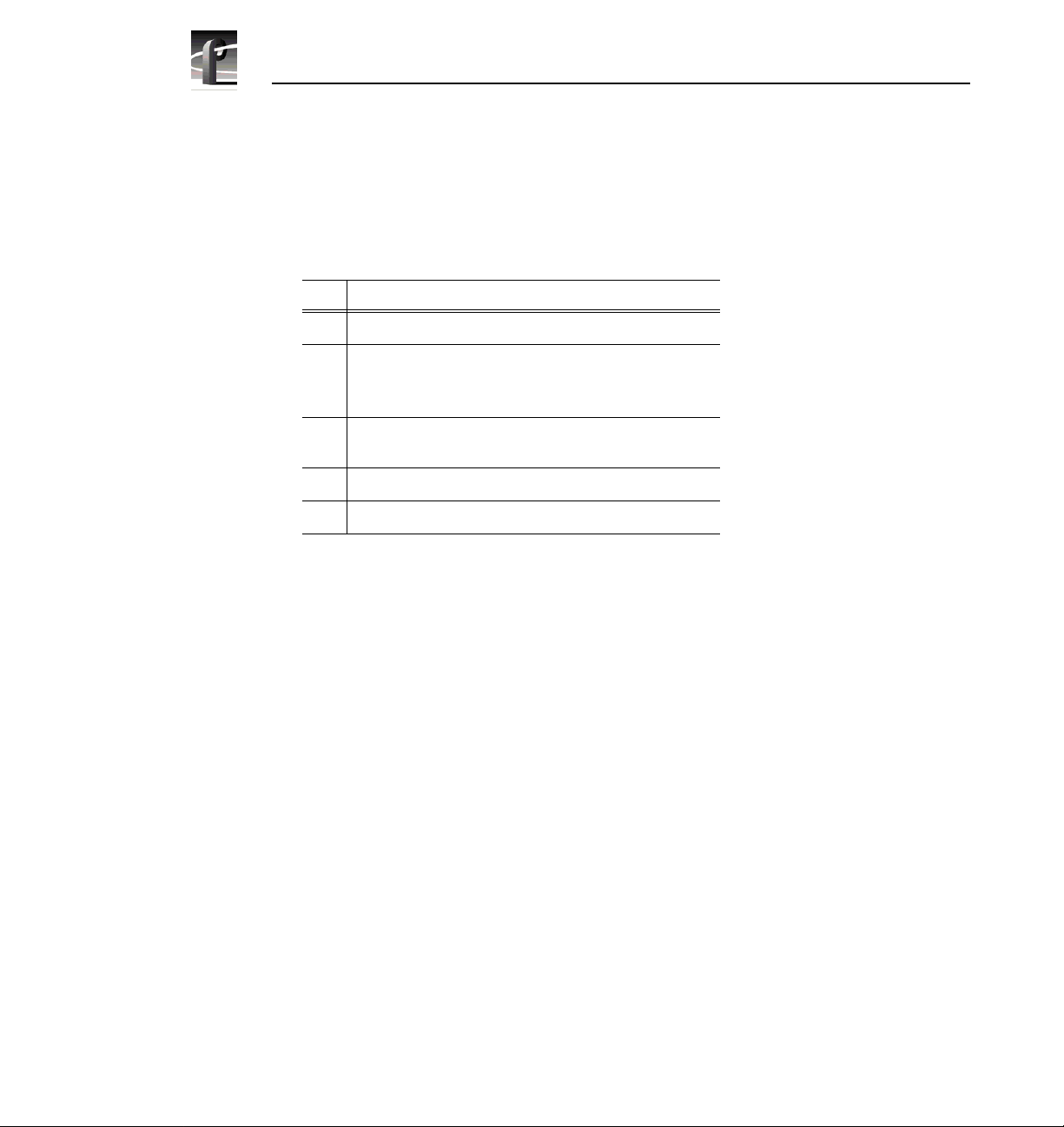
Table 2. Summary of installation procedur es
Procedures Page
Removing the Chassis Covers 15
Removing the Circuit Board Hold-down Brackets 16
Removing the RS-422 Interface Board 18
Installing the RS-422 Interface Board 22
Reinstalling Board Hold-down Brackets 24
Replacing the Profile Chassis Covers 27
Replacing the RS-422 Board Interface Cable 28
Number
Installing the RS-422 Interface Bo ard Device Driver 29
Verifying Installation 34
Copying the Driv er Diskette Conten ts to the System Drive 37
14 RS-422 Interfa ce Board Installation
Page 15

Removing the Chassis Covers
Use the following procedure to remove the chassis covers:
1. Confirm that the Profile system power is switched off a nd the power cord is
removed.
2. Use the Torx tool with the T10 tip to remove the top screws from the front
chassis cover (Ê in Figure 1) and then use the T15 tip to remove the
pan-headed screws from the side of the chassis. The fr ont chassis cover must
be removed first because it overlaps the rear chassis cover.
NOTE: Take care not to lose these chassis scre ws. They are require d to meet
the EMI sp e cificati o n s f o r the P r o f il e sys t e m.
Removing the Chassis Covers
2
1
9675-9
Figure 1. Removing the front and rear chassis covers
3. Use the Torx tool with the T10 tip to remove the rear chassis cover
(Ëin Figure 1) which covers the circuit boards.
RS-422 Interface Board Inst allation 15
Page 16

Installation Procedures
Removing the Circuit Board Hold-down Brackets
There are two hold-down brackets loc a ted in the circuit board area of the chassis
which must be removed in order to replace boards.
To remove the board hold-down brackets:
1. Use the Torx tool with the T10 tip to remove the exterio r screw
(Êin Figure 2) that secures the rear board hold-down bracket.
2. Lift the bracket (Ëin Figure 2) up and out of the chassis and set it aside.
3. Use the Torx tool with the T10 tip to remove the interior screw
(Ìin Figure 2) that secures the front board hold-down bracket.
4. Lift the bracket (Íin Figure 2) up and out of the chassis and set it aside.
16 RS-422 Interfa ce Board Installation
Page 17

Removing the Circuit Board Hold-down Brackets
3
4
2
9675-2
Figure 2. Removing the circuit board hold-down brackets
1
RS-422 Interface Board Inst allation 17
Page 18

Installation Procedures
Removing the RS-422 Interface Board
The RS-422 Interface board is a half-height board installed in motherboard slot
J17 as shown in Figure 4.
To the remove the RS-422 board from slot J17:
1. Free the SCSI cables from the cable clamps mounted on the power supply
(Ê in Figure 3) and position the cables away from slot J17 (Ëin Figure 3) .
1
Figure 3. Positioning SCSI cables away from slot J17
18 RS-422 Interfa ce Board Installation
2
0519-2
Page 19

Removing the RS-422 Interface Board
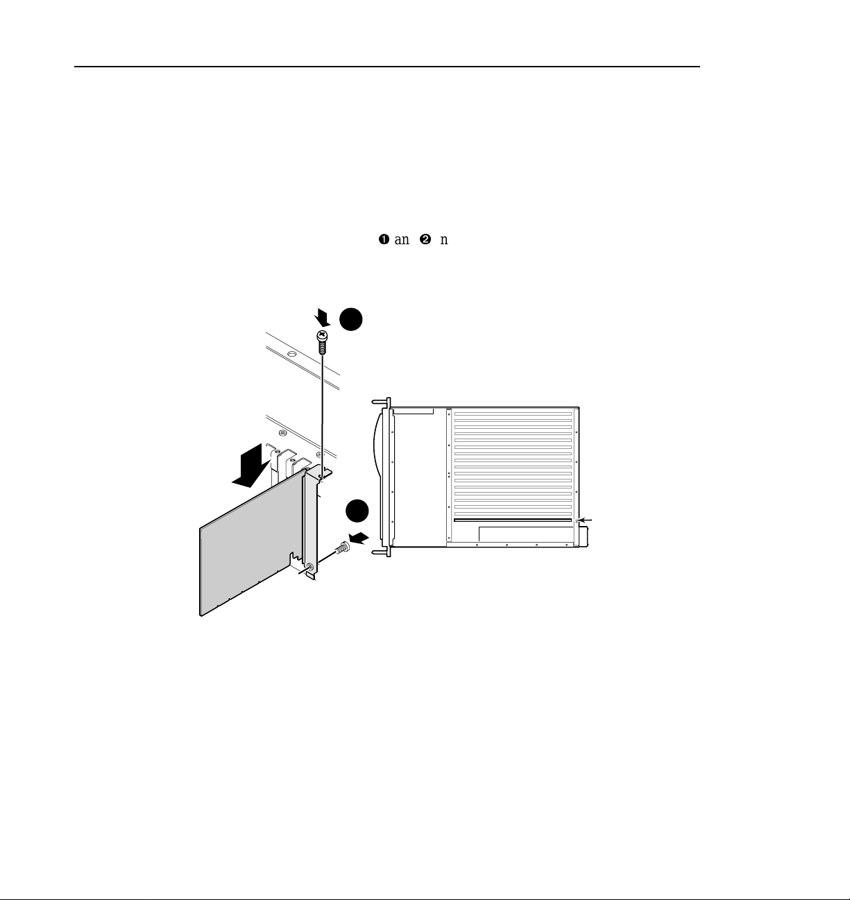
2. Use the Torx tool with the T15 tip to remove the screw from the board
mounting bracket inside the c hassis. Refer to the example board in Figure 4.
J17
0519-1
Figure 4. Removing the mounting bracket screw and RS-422 Int erface board.
RS-422 Interface Board Inst allation 19
Page 20

Installation Procedures
3. Carefully remove the RS-422 Interface board by grasping the edge of the
circuit board above the EISA connector and pulling up.
NOTE:
- Do not grasp or pull on the rear-panel connectors when removing or
installing the circ uit boards.
- It may be necessary to loose n the screw mountin g the Genloc k board in
slot J16.
- Some systems have full height Genlock boards which may have to be
removed to allow a firm grasp of the RS-422 board. Refer to the
following procedure.
Removing the Genlock Board For RS-422 Board Removal
Some Profile systems have full height Genlock boards in slot J16 which must be
removed to allow a firm grasp of the RS-422 board.
To remove the Genlock board from slot J16 for RS-422 board removal:
1. Remove all external a nd internal cables f rom the Genlock board. Be sure to
make a cabling diagram that you can use later to reinstall the cables.
2. Use the Torx tool with the T15 tip to remove the screws which secure the
Genlock board to the rear panel (see Ê and Ë in Figure 5 as an examp le).
3. Use the extraction lever on the front of the board and the extraction ring at
the back of the board to lift the circui t board f ree of the connectors on the
motherboard.
4. Carefully remove the RS-422 Interface board by grasping the edge of the
circuit board above the mothe rboard connector and pulling up.
20 RS-422 Interfa ce Board Installation
Page 21

Removing the RS-422 Interface Board
1
2
Figure 5. Mounting screw location for full height board
RS-422 Interface Board Inst allation 21
9040-13
Page 22

Installation Procedures
Installing the RS-422 Interface Board
To install the RS-422 interf ace board:
1. Verify the RS-422 Interfa ce board jumper and DIP switch settings (refer to
Figure 6).
Jumpers
12345678
ON
Figure 6. RS-422 Inter face board jumper and DIP switch settings
22 RS-422 Interfa ce Board Installation
JumpersDip Switches
0519-5
Page 23
Installing the RS-422 Interface Board
2. Align the RS-422 board with the mother board conne ctor in slot J17 (see
Figure 7). Firmly press down on the board until the board seats. The board is
properly seated when the top of the rear mounting bracket is resting on the
rear chassis wall shelf.
3. Use the Torx tool with the T15 tip to reinstall the scre ws which secure the
RS-422 board to the rear panel (see Ê and Ë in Figure 7).
1
2
Figure 7. Installing the RS-422 Interface board and mounting bracket screw
J17
0519-3
4. If you removed the Genlock board e arlier, reinstall it now by aligning it with
the connectors on the motherboard slot, making sure the extractor on the
front end of the board is in the up position. Firmly press down on the board
until the board seats a nd then rei nstall t he mounting screws (see Fi gure 5 on
page 21). Reconnect a ny internal cables removed earlier (refer to your
cabling diagram).
5. Place the SCSI cables back in the cable clamps mounted on the power
supply. (Refer to Figure 3 on page 18.)
RS-422 Interface Board Inst allation 23
Page 24

Installation Procedures
Reinstalling Board Hold- d own Brackets
Now that the RS-422 Interface board is installed, you are ready to reinstall the
board hold-down brackets. This involves modifying the front hold-down bracket
by removing the bracket extender for slot J17, since it is no longer needed.
To reinstall the board hold -down brackets:
1. Use the Torx tool with the T15 bit to remove the extender retaining screw
from the front hold-down bracke t as shown in F igure 8. Discard the extender
and screw.
0519-4
Figure 8. Removing the board hold-down extender for slot J17
24 RS-422 Interfa ce Board Installation
Page 25

Reinstalling Board Hold-down Brackets
2. Insert front hold- down bracket (Ê in Figure 9) into the board area and ensure
that the extenders are on the top edge of all short boards.
NOTE: To prevent damage to the Analog Composite M onitor board, if
installed, ensure that an extender is not installed at the Analog Composite
Monitor board location.
3. Use the Torx tool with the T10 bit to replace brack et retaining
screw (Ëin Figure 9).
2
1
3
Figure 9. Installing board hold-down brackets
4
9675-3
RS-422 Interface Board Inst allation 25
Page 26
Installation Procedures
4. Place rear hold-down brack et (Ì in Figure 9 on page 25) over the boards.
5. Align the full size boards to the correct bracket slots (see insert in Figure 9)
and carefully seat the bracket onto the boards.
6. Use the Torx tool with the T10 bit to replace brack et ret aining
screw (
Í
in Figure 9) at the side of the Profile syst em .
26 RS-422 Interfa ce Board Installation
Page 27

Replacing the Profile Chassis Covers
To replace the Profile chass is covers:
Replacing the Profile Chassis Covers
1. Set the rear chassis cover in place (
the T10 bit to secure the cover to the chassi s with the screws previously
removed.
NOTE: When reinstalling chassis cove rs, start all the screws before
tightening them. This ensures th at the screw threads are properly aligned,
and will help avoid stripping thre ads or breaking screws.
Ê
in Figure 10) and use the Torx tool with
1
2
0033-6
Figure 10. Replacing the Profile chassis covers
2. Set the front chassis cover in place (Ë in Figure 10) and use the Torx tool
with the T10 bit to i nstall t he screws which se cur e the cover to the to p of the
chassis. Use the T15 tip to install the screws which secure the cover to the
side of the chassis.
RS-422 Interface Board Inst allation 27
Page 28

Installation Procedures
Replacing the RS-422 Board Interface Cable
The kit includes a new interface cable for the RS-422 Connector Panel.
To replace the RS-422 Board interfa ce cable :
1. Reinstall the Profile system in the rack. If necessary, refer to the Profile
Installation Manual f or rack mounting instructions.
2. Replace the cable connect ing the RS-422 Connector Panel to the RS-422
Interface board with the cable supplied with this kit as shown in Figure 11.
J17 J13J16
J15 J14 J6J7
Remote I/O
RS-422
Figure 11. Connecting the RS-422 Connector Panel interface cable
J11 J9
J12
J10
J8
RS-422 Connector Panel
RS-422 Communications
(Ports 1-8)
J5
J4 J3 J2
J1
9676-62
3. Reconnect all other exte rnal cables previously removed.
4. Connect power to the Profile system and proc eed with “Installing t he RS-422
Interface Board Device Driver” on page 29.
28 RS-422 Interfa ce Board Installation
Page 29

Installing the RS-422 Interface Board Device Driver
Installing the RS-422 Interface Board Device Driver
Now that you have installed the RS-422 Int erface board, you are ready to install
the device driver software. The device driver software is the support software
Windows NT uses to access and operate the board. Befor e installing the new
device driver, you m ust re move the devic e drive r for RS- 422 board you r emoved.
Removing the Existing RS-422 Device Driver
1. Power On the Profile system and logon as Administrator using these steps.
a. Power On the Profile system and hold the
Shift key down during start-up
to prevent auto-logon as user profile. Be s u r e to hol d do wn th e shi ft key
until the logon dialog box appear s.
b. Logon as administrator. The factory default administrator password on a
Profile system is triton.
NOTE: Ignore the message “At least one servi ce or driver failed during
system start-up. Us e Event Viewer to examine the event log for det ails . ” The
failed driver is for the old RS-422 board you have already removed.
2. Open Control Panel by choosing
Start | Settings | Control Panel
3. Double-click the Network icon.
4. The Network dialog box appears. Click the
5. Highlight the
Digi ACL/Avanstar Family Adapter and then click the Remove
Adapters tab.
button.
6. When prompted “Do you wish to continue?” , click
Yes.
7. Close the Network dialog box.
8. When prompted, restart the system and logon again as Administrator.
You are now ready to install the new device driver.
RS-422 Interface Board Inst allation 29
Page 30

Installation Procedures
Installing the RS-422 Board Device Driver
After removing the old RS-422 board device dri ver and re-starting the system, you
are ready t o install the driver for t he new RS-422 board. Locate the Windows NT
driver diskette labeled Driver for the R ocketPort Series , then use the following
instructions to install the driver.
To install the RS-422 device drive r:
1. Make sure you a re logged on as Administrator. The factory default passwo rd
on the Profile system for Administrator is triton.
2. Open the Control Panel by choosing
Start | Settings | Control Panel
3. Double-click the Network icon.
4. The Network dialog box appears. Click the
5. Click the
Add button, and then the Have Disk... button.
Adapters tab.
6. When you are prompted, insert the Windows NT driver diskette. Type
A:\winnt as the path of the directory contain ing the driver files (see Figure 12)
and click
OK.
Figure 12. Typing the path to the de vice driver files.
30 RS-422 Interfa ce Board Installation
Page 31

Installing the RS-422 Interface Board Device Driver
7. The Select OEM Option dialog box appears (see Figure 13). Click OK. File
copying starts.
Figure 13. Select OEM Option window
RS-422 Interface Board Inst allation 31
Page 32

Installation Procedures
8. When the RocketPort/Rocket Modem NT Setup window appears, shown in
Figure 14, set
Leave the I/O Address at the default value: 180- 1c3 Hex.
Starting COM Port to COM3 using the drop-down list.
Figure 14. The RocketPort/RocketModem NT Setup window settings
32 RS-422 Interfa ce Board Installation
Page 33

Installing the RS-422 Interface Board Device Driver
9. From the Advanced menu (see Figure 14), select Options to open the
Advanced Board Options dialog box as shown in Figur e 15.
a. Set th e Scan Rate(ms) to 2ms by selecting the text in the text box and
entering 2. No te tha t 2 is not i n the dr op down list, you must e nter it using
the keyboard.
b. Click
OK to close the Advanced Board Option s dialog box.
Figure 15. The Advanced Board Options di alog box settings
10. In the RocketPort/RocketModem NT Setup window, select OK to accept
your changes, and then
OK again to make a new program group.
NOTE: If necessary, close the Explorer window showing the new program
folder contents in order to see the remaining dialog boxes.
11. Chose
12. Chose
OK to make changes to the modem.inf file.
OK to save new configuration settings.
13. Click Close in the Network dialog box.
14. Remove the floppy disk from the drive and, when prompted, restart the
system. Logon as Profile. The factor y default password for the Profile user
account is profile.
RS-422 Interface Board Inst allation 33
Page 34

Installation Procedures
Verifying Installation
Now you are ready to verify the RS-422 Interface board installation using
diagnostics re sident on the P rofile syst em. The RS-422 inter face boa rd dia gnostic
performs a loop-back test using a standard DB9 male-to-male cable. When the
loopback test is run, a simple communication routine is executed between ports P1
to P2, P3 to P4, and so on. Wit h a single cable, you can test one port pair a t a time.
To verify installation:
1. Power On the Profil e system and l ogon using t he user account c alled Profile.
The factory default passwor d the Profile user account is profile.
2. Quit all Profile applications and then start Profile Diagnostics by selecting
Start | Programs | PDR Debug Tools | PDR Diagnostics.
When the diagnostics window is firs t opened, you may see the following
message:
Wait approximately one minute for th is message to clear from the screen
before proceeding. If the message does not clear, cancel diagnostics and
make sure that you have quit all other Profile applications, then res tart
diagnostics.
Checking availability of VDR Services. Please wait.
3. If the dialog box with the message “About to re-start VDR SVC in test mode”
appears, click
OK.
4. In the Diagnostics window, click the
34 RS-422 Interfa ce Board Installation
RS-422 test button (see Figure 16).
Page 35

Verifying Installation
Slot J1
Slot J2
Slot J3
Slot J4
Slot J5
Slot J6
Slot J7
Slot J8
Slot J9
Slot J10
Slot J11
Slot J12
Slot J13
Slot J14
Slot J15
Slot J16
Slot J17
Mother Bd
Pentium CPU
Non-EI SA s l ot
SMCA010
BUS4202
Serial Cmpnt I/O (Rev x)
Audio
Audio
Serial Cmpnt I/O (Rev x)
Audio
Audio
Master EDR (Rev x)
Ref Gen (4 LTC) (Rev x)
RS422, if installed
Mother Board (Rev x)
Quit
RS-422
Test Button
Figure 16. PDR Diagnostics window example
RS-422 Interface Board Inst allation 35
Page 36

Installation Procedures
5. When the RS422 Test window appears as shown in Figure 17, follow the
on-screen instru ctions for performing the loop-back te st.
NOTE: Make a note of the switch positions on the RS-422 Connector Panel
before changing them to run the RS-422 diagnosti c test.
Figure 17 shows the correct test results when a cable is connected between
ports P1 and P 2.
Figure 17. RS-422 test results with a cable connecting ports P1 and P2
6. After you have finished verifying RS-422 board installation, shutdown and
restart Windows NT.
Now that you have c ompleted installa tion veri fication, proceed with “Copying the
Driver Diskette Contents to the System Drive” on page 37.
36 RS-422 Interfa ce Board Installation
Page 37

Copying the Driver Diskette Contents to the System Drive
Copying the Driver Diskette Contents to the System Drive
In this procedure you will copy the conte nts of the Windows NT driver diskette
onto the system drive. This will make it convenient if you need access to these file s
in the future.
To copy the contents of the Windows NT Driver Diskette:
1. Create a new folder under c:\profile\drivers called
comtrol.
NOTE: Som e Pr of ile sys tems already have th e devi ce d riv er softwa r e in th e
“comtrol” directory. If the device driver software is already on the system
hard drive, you can skip the rest of this procedure.
2. Copy all the files from the driver disket te
comtrol director y you just created.
A:\winnt directory to the new
3. Remove the Windows NT driver diskette.
This completes the RS-422 Interf ace board installation proc edure .
RS-422 Interface Board Inst allation 37
Page 38

Installation Procedures
38 RS-422 Interfa ce Board Installation
 Loading...