

Page 1

CopperHead RCP 2050 User Guide
M4001-9900-102
24 July 2014
Page 2

Notices
Copyright & Trademark Notice
Copyright © 2007–2014, Grass Valley. All rights reserved.
Belden, Belden Sending All The Right Signals, and the Belden logo are trademarks or
registered trademarks of Belden Inc. or its affiliated companies in the United States and
other jurisdictions. Grass Valley, CopperHead RCP 2050A Operational Control Unit are
trademarks or registered trademarks of Grass Valley. Belden Inc., Grass Valley, and other
parties may also have trademark rights in other terms used herein.
Terms and Conditions
Please read the following terms and conditions carefully. By using CopperHead RCP 2050
documentation, you agree to the following terms and conditions.
Grass Valley, a Belden Brand (“Grass Valley”) hereby grants permission and license to owners
of CopperHead RCP 2050 to use their product manuals for their own internal business use.
Manuals for Grass Valley products may not be reproduced or transmitted in any form or by
any means, electronic or mechanical, including photocopying and recording, for any
purpose unless specifically authorized in writing by Grass Valley.
A Grass Valley manual may have been revised to reflect changes made to the product
during its manufacturing life. Thus, different versions of a manual may exist for any given
product. Care should be taken to ensure that one obtains the proper manual version for a
specific product serial number.
Information in this document is subject to change without notice and does not represent a
commitment on the part of Grass Valley.
Warranty information is available in the Support section of the Grass Valley Web site
(www.miranda.com).
Title CopperHead RCP 2050 User Guide
Part Number M4001-9900-102
Revision 24 July 2014
ii
Page 3

Table of Contents
1 About CopperHead RCP 2050 . . . . . . . . . . . . . . . . . . . . . . . . . . . 1
About CopperHead RCP 2050 . . . . . . . . . . . . . . . . . . . . . . . . . . . . . . . . . . . . . . . . . . . . . . . . . . . . . . 2
Configuration . . . . . . . . . . . . . . . . . . . . . . . . . . . . . . . . . . . . . . . . . . . . . . . . . . . . . . . . . . . . . . . . . 2
Unpacking the CopperHead RCP 2050A Operational Control Unit . . . . . . . . . . . . . . . . . . .3
Product Returns . . . . . . . . . . . . . . . . . . . . . . . . . . . . . . . . . . . . . . . . . . . . . . . . . . . . . . . . . . . . . . . 3
About this User Guide . . . . . . . . . . . . . . . . . . . . . . . . . . . . . . . . . . . . . . . . . . . . . . . . . . . . . . . . . 3
2 Installation and Configuration . . . . . . . . . . . . . . . . . . . . . . . . . . 5
About the Installation . . . . . . . . . . . . . . . . . . . . . . . . . . . . . . . . . . . . . . . . . . . . . . . . . . . . . . . . . . . . . 6
Device Storage . . . . . . . . . . . . . . . . . . . . . . . . . . . . . . . . . . . . . . . . . . . . . . . . . . . . . . . . . . . . . . . . 6
Connectors. . . . . . . . . . . . . . . . . . . . . . . . . . . . . . . . . . . . . . . . . . . . . . . . . . . . . . . . . . . . . . . . . . . . . . . . 6
Main I/O Connector . . . . . . . . . . . . . . . . . . . . . . . . . . . . . . . . . . . . . . . . . . . . . . . . . . . . . . . . . . . 7
Camera Control Interface. . . . . . . . . . . . . . . . . . . . . . . . . . . . . . . . . . . . . . . . . . . . . . . . . . . . . . 7
Power . . . . . . . . . . . . . . . . . . . . . . . . . . . . . . . . . . . . . . . . . . . . . . . . . . . . . . . . . . . . . . . . . . . . . . . . 7
Tally Inputs . . . . . . . . . . . . . . . . . . . . . . . . . . . . . . . . . . . . . . . . . . . . . . . . . . . . . . . . . . . . . . . . . . . 7
Preview Output . . . . . . . . . . . . . . . . . . . . . . . . . . . . . . . . . . . . . . . . . . . . . . . . . . . . . . . . . . . . . . . 8
Preview Output Connector . . . . . . . . . . . . . . . . . . . . . . . . . . . . . . . . . . . . . . . . . . . . . . . . . . . .8
Video Input Connector . . . . . . . . . . . . . . . . . . . . . . . . . . . . . . . . . . . . . . . . . . . . . . . . . . . . . . . . 8
Video Output Connector . . . . . . . . . . . . . . . . . . . . . . . . . . . . . . . . . . . . . . . . . . . . . . . . . . . . . . 8
Engineering Setup. . . . . . . . . . . . . . . . . . . . . . . . . . . . . . . . . . . . . . . . . . . . . . . . . . . . . . . . . . . . . . . . . 9
Configuring the Emulation. . . . . . . . . . . . . . . . . . . . . . . . . . . . . . . . . . . . . . . . . . . . . . . . . . . . . 9
Adjusting the Camera Iris . . . . . . . . . . . . . . . . . . . . . . . . . . . . . . . . . . . . . . . . . . . . . . . . . . . . .10
TFT/LCD Screen adjustments . . . . . . . . . . . . . . . . . . . . . . . . . . . . . . . . . . . . . . . . . . . . . . . . .11
Calibrate Camera/Joystick . . . . . . . . . . . . . . . . . . . . . . . . . . . . . . . . . . . . . . . . . . . . . . . . . . . .12
Joystick Tension . . . . . . . . . . . . . . . . . . . . . . . . . . . . . . . . . . . . . . . . . . . . . . . . . . . . . . . . . . . . . 12
LED Illumination Test . . . . . . . . . . . . . . . . . . . . . . . . . . . . . . . . . . . . . . . . . . . . . . . . . . . . . . . . .12
Re-Programming Software/Firmware . . . . . . . . . . . . . . . . . . . . . . . . . . . . . . . . . . . . . . . . .13
3 CopperHead RCP 2050 Features . . . . . . . . . . . . . . . . . . . . . . . . 15
Controls. . . . . . . . . . . . . . . . . . . . . . . . . . . . . . . . . . . . . . . . . . . . . . . . . . . . . . . . . . . . . . . . . . . . . . . . . .16
Variable Adjust Buttons. . . . . . . . . . . . . . . . . . . . . . . . . . . . . . . . . . . . . . . . . . . . . . . . . . . . . . .16
Rotary Encoder . . . . . . . . . . . . . . . . . . . . . . . . . . . . . . . . . . . . . . . . . . . . . . . . . . . . . . . . . . . . . . . . . . .18
Function buttons . . . . . . . . . . . . . . . . . . . . . . . . . . . . . . . . . . . . . . . . . . . . . . . . . . . . . . . . . . . . . . . . .19
Emulation and Control Features. . . . . . . . . . . . . . . . . . . . . . . . . . . . . . . . . . . . . . . . . . . . . . . . . . .23
OSD Output . . . . . . . . . . . . . . . . . . . . . . . . . . . . . . . . . . . . . . . . . . . . . . . . . . . . . . . . . . . . . . . . . . . . . .25
Optional LCD/TFT Display. . . . . . . . . . . . . . . . . . . . . . . . . . . . . . . . . . . . . . . . . . . . . . . . . . . . . . . . .26
iii
Page 4

Table of Contents
4 Specifications . . . . . . . . . . . . . . . . . . . . . . . . . . . . . . . . . . . . . . . . . 29
A Dimensions and Cables. . . . . . . . . . . . . . . . . . . . . . . . . . . . . . . . . 32
Physical Dimensions . . . . . . . . . . . . . . . . . . . . . . . . . . . . . . . . . . . . . . . . . . . . . . . . . . . . . . . . . . . . . .33
CopperHead Cables . . . . . . . . . . . . . . . . . . . . . . . . . . . . . . . . . . . . . . . . . . . . . . . . . . . . . . . . . . . . . .34
For cameras using RS422 Protocol . . . . . . . . . . . . . . . . . . . . . . . . . . . . . . . . . . . . . . . . . . . .34
For cameras using RS232 Protocol . . . . . . . . . . . . . . . . . . . . . . . . . . . . . . . . . . . . . . . . . . . .35
For cameras using Bi-directional TTL Protocol . . . . . . . . . . . . . . . . . . . . . . . . . . . . . . . . .36
iv
Page 5

About CopperHead RCP 2050
This chapter provides an overview of the CopperHead RCP 2050A Operational Control Unit
and includes the safety and warranty information about it.
About CopperHead RCP 2050 . . . . . . . . . . . . . . . . . . . . . . . . . . . . . . . . . . . . . . . . . . . . . . . . . . . . . . . . . . 2
Unpacking the CopperHead RCP 2050A Operational Control Unit . . . . . . . . . . . . . . . . . . . . . . 3
1
Page 6
About CopperHead RCP 2050
About CopperHead RCP 2050
About CopperHead RCP 2050
The CopperHead RCP 2050A Operational Control Unit provides remote control facilities for a
range of broadcast cameras/camcorders from several different manufacturers. It has been
designed to emulate control units from Hitachi, Ikegami, JVC, Panasonic, and Sony. The
2050A interfaces directly with Fiber Systems’ CopperHead fiber optic extension systems, or
can be connected directly to a camera or a camcorder.
The 2050 provides reliable, noise free, non-contact joystick controls of iris, pedestal and
preview. Joystick tension is easily adjustable.
The main connector is a DB15 type which is reliable, economical, and readily available. This
connector carries camera control data, power, and Red and Green tally inputs and preview
volt-free contacts. Preview contact closure is also available on a BNC coax connector.
Composite video monitor input and video output are available on BNC connectors.
Multiple non-volatile storage and retrieval scene files are available both internally and via
SD card access. The SD card allows scene file settings to be transported across multi-channel
systems as well as off-site backup.
An On Screen Display (OSD) video output provides operational information and SD scene file
access menus. This OSD output can be connected to an external standard definition
composite VBS monitor or, optionally, a tiltable 3.5 inch (89mm) TFT-LCD unit is available
(Fiber Systems CHRCP-LCD1) which is designed to match and fit the 2050.
The 2050 will function over a large supply voltage range with low power consumption. If the
TFT-LCD is fitted this supply voltage range is reduced.
For in-desk fitment, the low-profile design of only 40mm below desktop surface gives
maximum under desk clearance. Panel mounting brackets are available for this purpose.
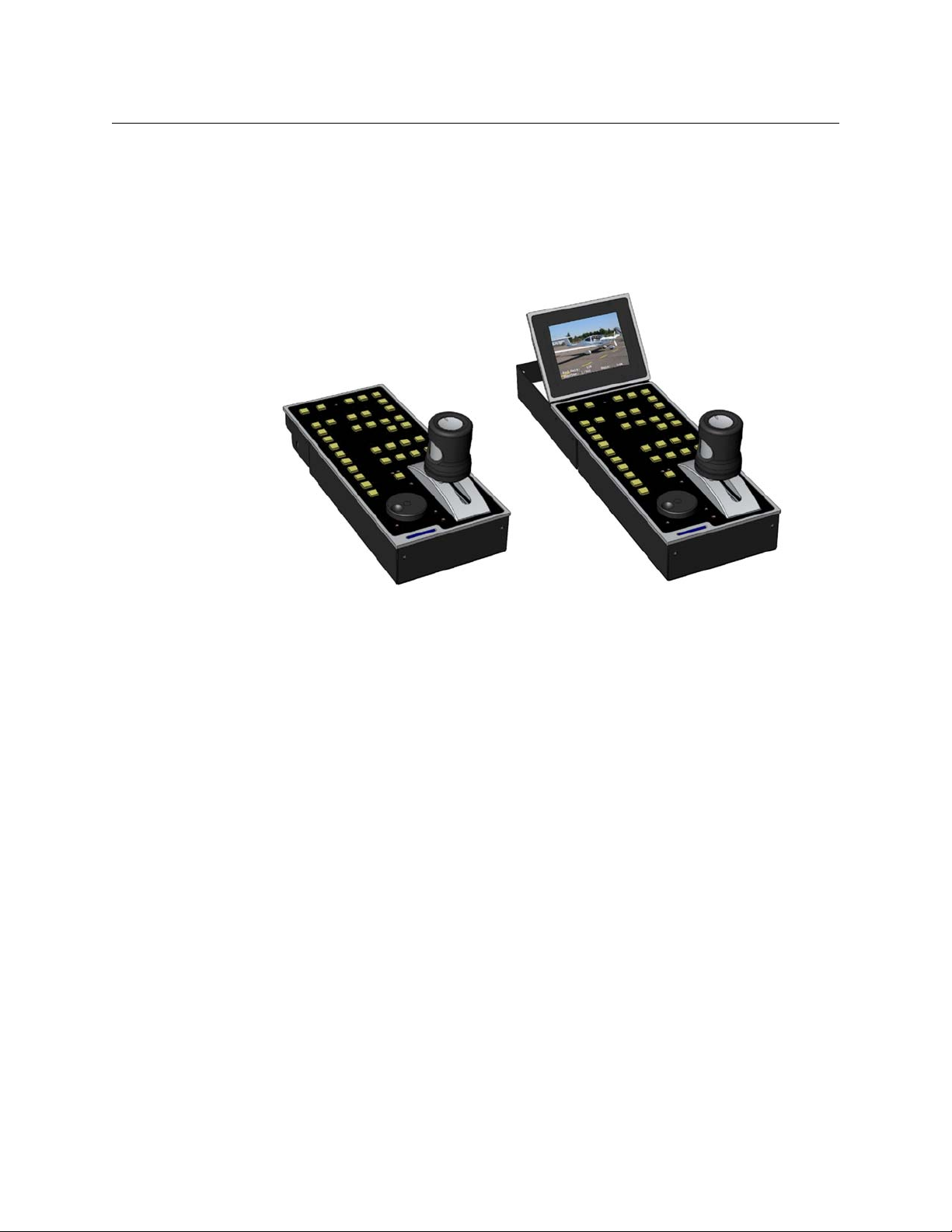
Configuration
Fig. 1-1: CopperHead RCP 2050A Operational Control Unit
The CopperHead RCP 2050A Operational Control Unit has been supplied configured to
emulate the control panel specified on your order or otherwise agreed. You can see other
emulations by following the procedure in Engineering Setup on page 9.
2
Page 7

CopperHead RCP 2050
User Guide
Unpacking the CopperHead RCP 2050A Operational Control Unit
Individual items shipped with a CopperHead RCP 2050 system depend on the particular
configuration.
Please consult your packing slip and purchase order to ensure that you have received all of
the expected Fiber Systems components. Inspect all components for scratches and other
mechanical damage, and inspect the electrical connectors for bent or damaged pins and
latches. Report any missing or damaged components to Grass Valley. See Product Returns
on page 3 regarding product returns.
You must use your own video and audio cables to make connections for Video, Tally, Black
Burst/Genlock, Base Station monitor, intercom, and other ancillary signals and equipment.
Suggestions for these cables are discussed later in Dimensions and Cables on page 32.
Product Returns
In the unlikely event of damage to your CopperHead RCP 2050A Operational Control Unit
during shipping or delivery please note the damage with the delivery or shipping service
and document the packaging and product where you see damage. If any component does
not work correctly out of the box, please contact Grass Valley (see Contact Us on page 31).
If the problem cannot be remedied through a service telephone call,you will receive an
RMA number (Return of Merchandise Authorization). Please note this RMA number inside
and outside of all shipping boxes and on all documentation provided with the items to be
returned.
About this User Guide
This user guide is designed to cover all of the various options and so not every page in this
guide will apply to your specific system.
3
Page 8

About CopperHead RCP 2050
About this User Guide
4
Page 9

Installation and Configuration
This chapter explains how to install and configure the CopperHead RCP 2050 system, as
well as how to configure the engineering settings.
About the Installation . . . . . . . . . . . . . . . . . . . . . . . . . . . . . . . . . . . . . . . . . . . . . . . . . . . . . . . . . . . . . . . . . 6
Connectors . . . . . . . . . . . . . . . . . . . . . . . . . . . . . . . . . . . . . . . . . . . . . . . . . . . . . . . . . . . . . . . . . . . . . . . . . . . . 6
Engineering Setup . . . . . . . . . . . . . . . . . . . . . . . . . . . . . . . . . . . . . . . . . . . . . . . . . . . . . . . . . . . . . . . . . . . . . 9
5
Page 10
Installation and Configuration
Video
Output
Video
Input
Preview
Output
Main I/O
About the Installation
About the Installation
The unit has low power dissipation and does not require any special ventilation
requirements. It may be used free standing or with optional brackets, mounted into a desk
top. All cables leave the OCU from the rear. Because of the unit's low profile height, the rear
connector panel may be tilted downwards to provide easier access as necessary for cabling
when mounted in- desk. To do this loosen the screw either side of the connector panel (in
the slot) and tilt the panel as required, re-tighten the screws.
Device Storage
As with all electronic equipment, both high and low temperature extremes should be
avoided as well as the ingress of moisture and dust. The units are rugged in construction,
but sharp shocks and high levels of vibration must also be avoided. Keep the unit within the
limits defined in the specification.
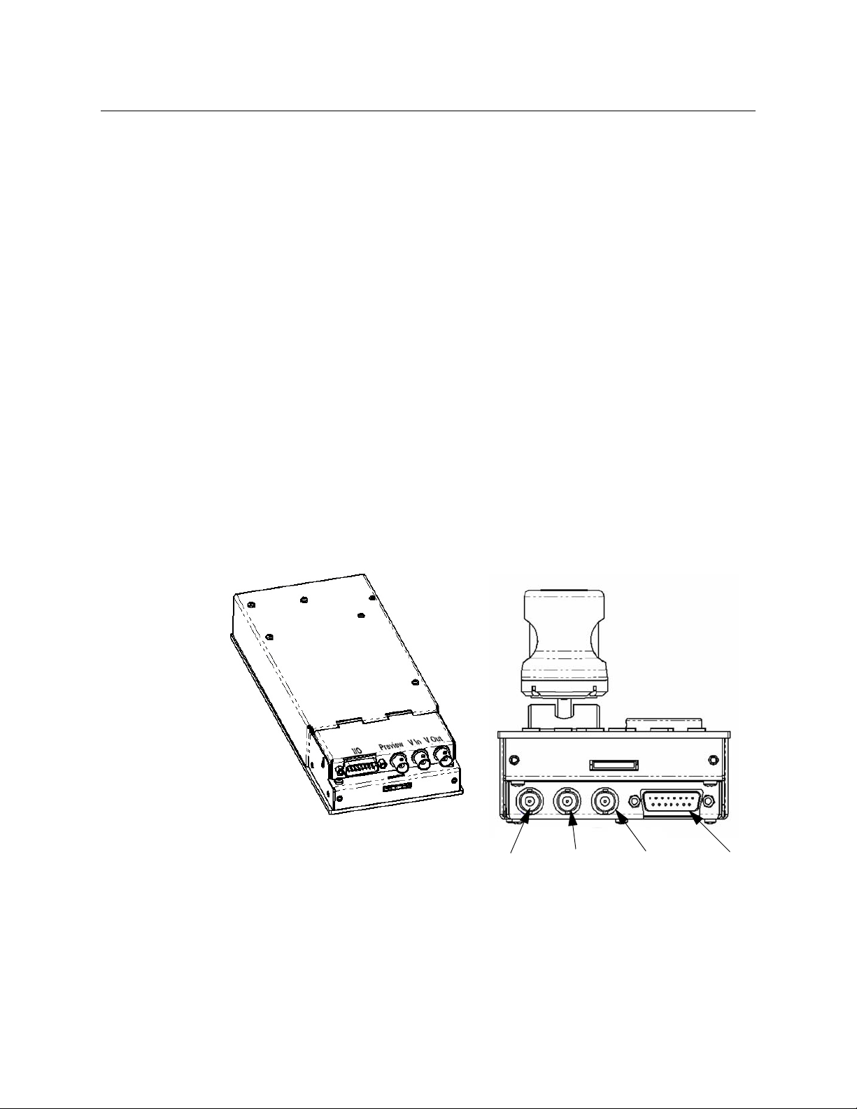
Connectors
The CHRCP2050A has four connectors:
•Main I/O (DB15)
•Preview Output (BNC)
•Video Input (BNC)
•Video Output (BNC)
Fig. 2-1: Rear Panel Connectors
6
Page 11

Main I/O Connector
The Main I/O connector is a DB15 female, and carries data, power, and Tally Inputs.
Pinouts are as follows:
CopperHead RCP 2050
User Guide
Fig. 2-2: DB 15 Male Plug
• Pin 1: GND
• Pin 2: RS422 Out+
• Pin 3: RS422 In-
• Pin 4: REM /EN
• Pin 5: +SUPPLY
• Pin 6: PREVIEW 1
• Pin 7: PREVIEW 2
• Pin 8: GND
• Pin 9: TALLY RED
• Pin 10: RS422 Out-
• Pin 11: RS422 In+
• Pin 12: TALLY GREEN
• Pin 13: RS232 In
• Pin 14: RS232 Out
• Pin 15: Bi-Directional I/O
Camera Control Interface
Camera Control is connected via various pins the MAIN I/O connector to your CopperHead
Base Station or directly to a camera. The OCU has four electrical control interfaces (RS422,
RS232, "Sony bi-di," and "Panasonic bi- di") which are automatically determined when each
emulation is selected. However, they can be changed via the "ENGr" menu if necessary for
type and sense (see Engineering Setup on page 9).
Power
The CHRCP2050A runs on DC power, which is supplied from the CopperHead Base Station
or directly from the camera, and is supplied via the MAIN I/O connector. If the
camera/camcorder does not have enough power to supply the OCU and/or TFT-LCD, an
optional connector and AC adaptor are available for powering the units externally.
Note: When the 2060 TFT-LCD display is attached, the power supply
voltage range is reduced(see Specifications on page 29).
Tally Inputs
Tally inputs are found on the MAIN I/O connector (DB15). Both Red and Green tally inputs
are available. These can be configured for either voltage or contact closure. Voltage must
be positive reference ground. Contact closure is also reference ground. An open collector
bipolar NPN transistor or open drain N channel FET may also drive the inputs. Configuration
is via the ENGr menu.
The panel tally LED is a bi-color Red/Green with the priority Red.
7
Page 12

Installation and Configuration
Preview Output Connector
Preview Output
A volt-free solid state contact closure is available as standard. This is activated when the
joystick knob is pushed down. Observe the contact ratings defined in the specifications.
The contacts are not polarity conscious. This contact closure is duplicated on the Preview
Output BNC.
Preview Output Connector
The same Preview output contact closure found on the Main I/O Connector (Preview
Output 3.2.1.4, above) is duplicated on this BNC.
Pinout specifications are as follows:
Inner Outer
BNC coax Preview1 (volt free contact 1) Preview2 (volt free contact 2)
Video Input Connector
The video BNC input is terminated in 75 ohms and accepts standard definition 1V p-p video
- composite sync, Y, or VBS.
Pinout specifications are as follows:
BNC coax
Video Output Connector
A valid video input is switched directly to the video output. When the MON button is
activated, the OSD characters are superimposed onto the video in white with a black
border to make them easily readable with varying program content.
If no video input is applied, the video output is Composite Sync with black background and
OSD superimposed, without color subcarrier. BNC output video is sourced in 75 ohms and
gives 1V p-p when correctly terminated in 75 ohms.
The output video is also available on the multi-way connector for the optional 3.5 inch TFTLCD display (2060).
Pinout specifications are as follows:
BNC coax
Inner Outer
1V p-p 75 ohms Ground
Inner Outer
1V p-p 75 ohms Ground
8
Page 13
Engineering Setup
Connect the unit to the CopperHead Base Station and turn on the power to the camera
head. If no LCD screen is attached, then connect the Video Output BNC of the unit to an
external monitor.
When the ENGr button is pressed, the OSD displays the unit's Engineering Menu. There are
four pages of menus. Use the Rotary Encoder to scroll thru the selections. Push the Rotary
Encoder to select one of the menu items, or to change to the next page.
Note: A camera/camcorder needs to be connected for full access to
Engineering menus.
When switching emulations, ensure that rotary encoder is pressed to confirm the selection
before exiting the menu. When switching emulations, it is necessary to calibrate the
joystick each time.
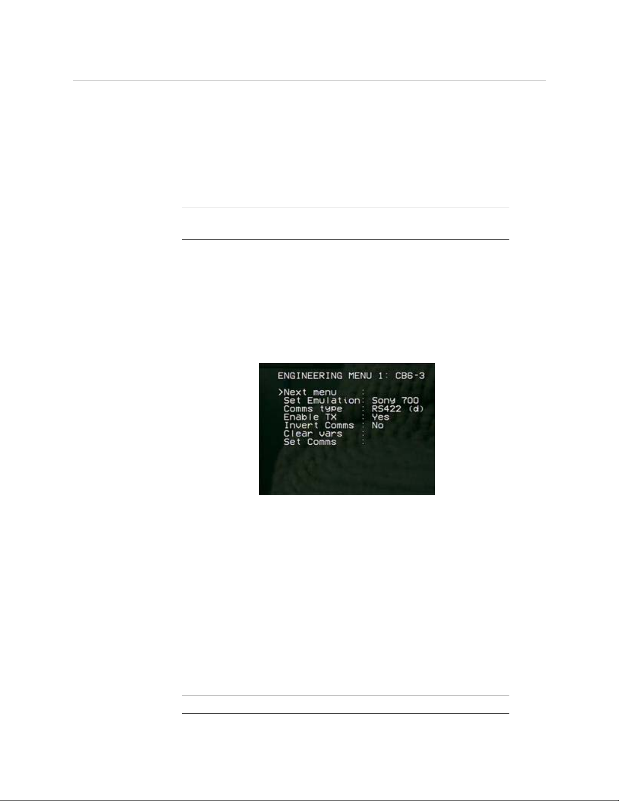
Configuring the Emulation
Because every manufacturer’s RCP is slightly different, you must configure the emulation
correctly so that the universal remote control panel works correctly.
CopperHead RCP 2050
User Guide
Fig. 2-3: Engineering Menu, Page 1
To configure the Emulation:
1 Select MON to turn on the On Screen Display and then ENGR menu. The first page of
the ENGR menu will appear.
2 Using the rotary control, select SET EMULATION and push down once. The appropriate
emulation type can now be selected by scrolling through the available options and
pressing down on the rotary control to confirm.
3 Once the appropriate emulation type is confirmed, scroll down to SET COMMS and
select by pressing down on the rotary control. This will automatically set the required
I/O parameters.
4 Exit the ENGR menu to confirm all of the settings. It may be necessary to switch the
camera head OFF/ON for communication to be established.
The iris range of the joystick can be adjusted to suit individual users or cameras.
Note: A camera/camcorder is required to be connected and operational.
9
Page 14

Installation and Configuration
Adjusting the Camera Iris
Adjusting the Camera Iris
To configure the Camera/Joystick Iris:
1Turn AUTO IRIS off.
2 Pull joystick toward minimum iris position (all the way back towards you) and set
MASTER PEDESTAL knob to mid- point.("12 O'Clock")
3Press ENGR to enter the ENGINEERING screen.
4 Using the rotary control click on NEXT MENU until you reach ENGINEERING MENU 2.
5 Select Cal Joy\Ped with rotary encoder and then push rotary encoder to set. The display
will report Done.
6Scroll down to Joystick min and press the rotary encoder switch. The OSD will report
Joystick min: Busy and display the iris value.
7 Use the rotary encoder to set the camera's iris to the Closed position, ideally by viewing
the iris ring on the lens of the camera. If this is not possible due to the location of the
camera, then set the iris value to the Closed position according to the On Screen
Display message (see notes below).
8 Once the iris is set to the Closed position, press the rotary encoder to confirm the
setting and the display will change from Busy to Done.
9 Push the joystick all the way forward and select Joystick Max and press the rotary
encoder switch. The OSD will report Joystick max: Busy and display the iris value.
10 Use the rotary control to set the camera's iris to the fully open position, ideally by
viewing the iris ring on the lens of the camera. If this is not possible due to the location
of the camera, then set the maximum iris value to the Open position according to the
On Screen Display message (see notes below).
11 Once the iris is set to the open position, click the rotary control to confirm the setting
and the display will change from Busy to Done.
12 Press ENGR to exit.
13 Check that the iris can be controlled by the joystick across the complete range.
Fig. 2-4: Engineering Menu, Page 2
10
Page 15

Note:
• Normally the joystick iris control range is set so that it matches the
camera iris range, but it is possible to adjust the settings MIN & MAX
so that a large movement of the joystick controls a small camera iris
movement for fine control. Simply adjust the rotary encoder for lens
iris positions that are required relative to the joystick position.
• Some Sony camera models allow iris adjustment across a range
between approximately 038 minimum and 110.
• Always adjust the minimum control position first.
TFT/LCD Screen adjustments
CopperHead RCP 2050
User Guide
Fig. 2-5: Engineering Menu, Page 3
Page 3 of the Engineering menu allows you to control four aspects of the built-in optional
LCD/TFT screen. Each has a range of 0 to 255. Default is 128
• Brightness: adjust from 0 to 255. Push the Rotary Encoder to select.
• Contrast : adjust from 0 to 255. Push the Rotary Encoder to select.
• Colour: adjust from 0 to 255. Push the Rotary Encoder to select.
• Tint: adjust from 0 to 255. Push the Rotary Encoder to select.
• Tes t L ED s : when selected, the test will start by illuminating tally (Red and Green), and
then illuminate the buttons in groups and end with the blue leds. The OCU will then
revert to normal operation.
Note that the SHUTTER
▲▼ and GAIN ▲▼ buttons do not illuminate.
11
Page 16

Installation and Configuration
Calibrate Camera/Joystick
Calibrate Camera/Joystick
Page 4 of the Engineering menu allows you to enable or disable control of various camera
functions, as well as to calibrate the joystick for your particular camera:
• Variables: On or Off
• Main Ped: On or Off
• Shutter: On or Off
• Iris: On or Off
• Gain: On or Off
Fig. 2-6: Engineering Menu, Page 4
Joystick Tension
Joystick tension may be adjusted to personal preference using the adjuster screw, which is
accessible through a hole in the under side of the unit directly under the centre of the
joystick when centrally positioned.
LED Illumination Test
Note that a camera/camcorder does not need to be connected.
Adjustment Procedure:
1Switch the OCU to OFF.
2 Press and hold ENGr button, press the ON/OFF button.
The test will start by illuminating tally and then illuminate the buttons in groups and end
with the blue leds. The OCU will then revert to normal operation.
Note that the SHUTTER
▲▼and GAIN ▲▼ buttons do not illuminate.
12
Page 17

Re-Programming Software/Firmware
The OCU may be field re-programmed with software/firmware updates. Two programming
connectors are available underneath the rear connector panel
• one for processor software
• one for for FPGA firmware.
To access these connectors, remove the two connector panel adjusting screws (in the slots
either side) and raise the panel up. The connectors are marked appropriately.
An optional programming kit is available for this purpose. Software and the reprogramming procedure are available from Fiber Systems Customer Support (see Contact
Us on page 31).
CopperHead RCP 2050
User Guide
13
Page 18

Installation and Configuration
Re-Programming Software/Firmware
14
Page 19

CopperHead RCP 2050 Features
This chapter describes the main CopperHead RCP 2050 features including the controls,
buttons, display, and OSD Output.
Controls . . . . . . . . . . . . . . . . . . . . . . . . . . . . . . . . . . . . . . . . . . . . . . . . . . . . . . . . . . . . . . . . . . . . . . . . . . . . . . 16
Rotary Encoder . . . . . . . . . . . . . . . . . . . . . . . . . . . . . . . . . . . . . . . . . . . . . . . . . . . . . . . . . . . . . . . . . . . . . . . 18
Function buttons . . . . . . . . . . . . . . . . . . . . . . . . . . . . . . . . . . . . . . . . . . . . . . . . . . . . . . . . . . . . . . . . . . . . . 19
Emulation and Control Features . . . . . . . . . . . . . . . . . . . . . . . . . . . . . . . . . . . . . . . . . . . . . . . . . . . . . . 23
OSD Output . . . . . . . . . . . . . . . . . . . . . . . . . . . . . . . . . . . . . . . . . . . . . . . . . . . . . . . . . . . . . . . . . . . . . . . . . . 25
Optional LCD/TFT Display . . . . . . . . . . . . . . . . . . . . . . . . . . . . . . . . . . . . . . . . . . . . . . . . . . . . . . . . . . . . 26
15
Page 20

CopperHead RCP 2050 Features
Controls
Controls
The following descriptions indicate the full potential control of the CHRCP-2050A but do
NOT imply that all controls are available for any particular control panel emulation.
Cameras and controllers differ considerably in the functionality they offer. Refer to
Emulation and Control Features on page 23 for available control features.
All camera settings and adjustments must be read with reference to the emulated control
panel and specific camera manuals.
Variable Adjust Buttons
The variable adjust buttons along the unit's left side allow digital bit increment and
decrement of the parameter selected with the rotary encoder. A flashing illuminated
variable button means that the rotary encoder is active for this item. The 'adjust' LED should
be illuminated. The variable value is shown on the OSD. A steady illuminated variable
button means the parameter value previously varied is now fixed and operational.
To adjust a parameter, select by pressing the appropriate button once. The button will flash
if the parameter is available. The camera will be updated with the value associated with the
parameter and adjustment can be made.
• A flashing illuminated variable button means someone is using the rotary encoder to
change its setting. The dual mode GAIN display indicates the variable value with an
inverted display.
• A steady illuminated variable button means the parameter value is fixed and
operational.
• If the button is pushed, again the LED will extinguish and the previous parameter value
will be reinstated. To retain the adjusted value, leave the LEDs on.
• If another parameter adjustment is required, press the appropriate button. The
previous button will go to steady illumination indicating that its particular value has
been retained and the new button will flash indicating the new parameter adjustment
active.
• To switch off a previously fixed parameter, press its button twice. Once will force the
parameter adjustment active and the second will turn it off.
16
Page 21

CopperHead RCP 2050
1. SHUTTER
2. RED GAIN
3. BLUE GAIN
4. RED PED
5. BLUE PED
6. KNEE
7. GAMMA
8. DETAIL
9. IRIS
User Guide
Fig. 3-1: Panel's Variable Adjust Controls
Parameter Description
1. SHUTTER Variable adjustment of shutter value.
2. RED GAIN* Adjusts red amplitude level
3. BLUE GAIN* Adjusts blue amplitude level
2&3. GREEN GAIN* Adjusts green amplitude level. Only available on certain cameras.
4. RED PED* Adjusts red pedestal (black) level
5. BLUE PED* Adjusts blue pedestal (black) level
6. KNEE Adjusts the variable knee camera characteristic.
17
Page 22

CopperHead RCP 2050 Features
Rotary Encoder
Parameter Description
7. GAMMA Adjusts the camera gamma characteristic.
8. DETAIL Adjusts the picture edge detail. Some call it 'Contour' or aperture
9. IRIS Inhibits the joystick IRIS control. Varies the iris as the joystick.
Note: Color GAIN and PED Adjustments can be adjusted by pushing
each individual button, or for quicker access, by pushing down on the
ROTERY ENCODER (10) to cycle between RED, BLUE, and GREEN (when
available).
Rotary Encoder
The encoder allows bit increment and decrement of the selected value.
correction.
Selecting IRIS AUTO reduces the sensitivity of control, allowing small
variation of the auto setting. This is camera dependant. Some
cameras do not allow any adjustment in IRIS AUTO mode.
The encoder also has a push switch. This is used in some emulations to switch between
functions. Refer to 'Control Features Chart'.
•If either 'RED GAIN' or 'BLUE GAIN' LEDs are active (flashing), pushing the switch will
swap control to the other.
•If either 'RED PED' or 'BLUE PED' LEDs are active (flashing), pushing the switch will swap
control to the other.
18
Page 23

Function buttons
12 13 14 15
11
19
21
22A
22B
26A
26B
26C
16
17
18
20A
20B
20C
20D
20E
20F
24
23
25
CopperHead RCP 2050
User Guide
Fig. 3-2: Function buttons
19
Page 24

CopperHead RCP 2050 Features
Function buttons
Buttons Description
11. ON/OFF OCU on/off.
12 CALL Performs call function with the camera. Usually this means
13. VTR Switches the scene file and MODE buttons to VTR mode - on or off
14. BARS Toggles camera color bars on and off.
15. MON Switches on or off the color monitor On Screen Display characters
16. ENGR Switches on and off the Engineering setup menus.
17. MENU Switches the camera menu on and off if applicable.
18. GAIN Increments or decrements the fixed gain value shown on the OSD.
19. SHUTTER Increments or decrements the fixed shutter value shown on the
Toggles the OCU on/off. On power-up, the LED flashes indicating
that the OCU is acquiring comms with the camera. The LED attains
steady state when comms are correctly established and the last
saved scene file is recalled and applied.
flashing the tally lights on the camera and the viewfinder. This can
vary with camera type or camera settings.
as applicable.
(OSD).
When on, the rotary encoder is enabled for item selection and
adjustment.
OSD. To turn shutter OFF, hold down the DOWN button for two
seconds.
20. BALANCE
20A.COLOR Enables variable adjustment of the 4 color balance controls.
20B. AUTO2 Applies auto balance 2.
20C. AUTO1 Applies auto balance 1.
20D. PRESET Sets the camera internal preset color balance levels.
20E. AWB Performs an auto-white balance.
20F. ABB Performs an auto-black balance.
21. SCENE FILE 1 - 4 Saves and recalls 5 complete OCU settings. On power-up the last
saved scene file is recalled.
• To save a fil e - press and hold the button to save for
approximately 2.5 seconds until all four scene file buttons are
illuminated. On release of the button the single stored scene file
button then illuminates.
• To recall a file - press a button momentarily for less than 2
seconds. The selected file button then illuminates.
De-selecting a scene file (pressing illuminated button - all files off)
recalls the user default file which can be a starting point for
setting a new scene file. This file is stored by pressing button 1
followed by button 4 within 2.5 seconds. Factory default settings
can be recalled by pressing 'CALL' followed by 'TEST' buttons.
20
Page 25

Buttons Description
21A. ALTERNATE FUNCTIONS
CopperHead RCP 2050
User Guide
<<
■
VTR mode fast rewind
VTR mode stop
||► VTR mode pause/play
>>
SD When an SD card is inserted, Scene File 1 button enables access to
22. KNEE Adjust the camera knee characteristic.
22A. Preset Sets the camera preset knee value.
22B. Auto Selects the camera auto knee function.
VTR mode fast forward
the SD OSD menu. Previously stored scene files may be retrieved
or the currently applied scene file saved to SD.
Before using an SD card for the first time please see the
specifications section to ensure compatibility. Additionally, the SD
card must first be formatted on a PC to create a FAT16 Master Boot
Record. The SD card can then be formatted in the unit by
selecting the 'Format Card' option.
When selecting a scene file to be saved, the filename will change
to indicate the one selected. In the example above Scene File 4
has been selected for saving. The filename can be edited using
the Change Description option before saving.
When retrieving the scene file using the load option, the scene file
is loaded into the scene file 1 position. To transfer these settings
to another scene file, exit the SD Menu and save to one of the
other available locations, e.g. Scene File 2.
23. BLACK STRETCH Adjusts the picture in the black region allowing more picture
content to be seen.
24. IRIS AUTO Sets camera auto iris mode. Most cameras automatically adjust iris
to the correct level and allow small adjustment of this level via the
joystick 'IRIS' or variable controls.
25. MODE When MODE is off, camera iris and pedestal values are updated
immediately when switching between variable IRIS, joystick IRIS
and when selecting different scene files. When MODE is on,
joystick IRIS and PED adjustments pick up control only when the
current camera values have been reached with the controls. This
prevents potentially large changes occurring after switching and
when not desired (e.g. live on air).
The IRIS and PED leds only illuminate when the controls are
active.
Other MODE settings are also reserved for future functions.
ALTERNATE FUNCTION
Rec: VTR mode Record if media is present in camcorder.
21
Page 26

CopperHead RCP 2050 Features
Function buttons
Buttons Description
26A. IRIS Control of lens iris using non-contact technology for noiseless,
26B. PREVIEW Pushing the joystick downwards enables the preview volt-free
26C. PEDESTAL Controls video black level pedestal. When the MASTER PED LED is
smooth and reliable operation.
•When the IRIS LED is illuminated, the Joystick IRIS is in control.
•When IRIS Auto is selected, Joystick IRIS has a reduced control.
•While IRIS Var is selected, Joystick IRIS is turned off.
See MODE for additional information.
contact closure. This electronic circuit uses a non-contact sensor
and a solid state output relay for reliability.
illuminated the Joystick PED is in control. See MODE for
additional information.
22
Page 27

Emulation and Control Features
Manufacturer: Panasonic Sony Sony Sony JVC Hitachi
Emulation: RC-10G RM-M7G RCP-TX7 700 (RMB) RM-LP25 RC-Z2
ON/OFF
CALL
VTR - Controls
- Stop
- Play
- Pause Play
- Fast Forward
- Fast Rewind
- Review Fwd
- Review Rev
- Review Clip
- Record
- Record Pause
BARS
ENGr Menu
MENU - Camera
SHUTTER - Speeds
- Variable
- Norm
GAIN - Auto
-Levels
BALANCE - Color
- Red Gain
- Blue Gain
- Red Ped
- Blue Ped
- Relative to AWB\ABB
- Preset
- Auto1
- Auto2
- ABB
- AWB
SCENE FILE 0 - 4
●●●● ●●
●◄
●●
●●
●
●
●
●
●
●
●●
●
●●●● ●●
●●●● ●●
●●
●●●●
●●●●
●
●
●●●● ●●
●●●● ●●
●●●● ●●
●●●● ●●
●●●● ●●
●●
●●●● ●●
●●●● ●●
●●●● ●●
●●●● ●●
●●●● ●●
●
+
+
+
●● ●
●● ●●
●● ●
▼
▼
▼
▼
▼
▼
●
▼
CopperHead RCP 2050
User Guide
+
23
Page 28

CopperHead RCP 2050 Features
Emulation and Control Features
Manufacturer: Panasonic Sony Sony Sony JVC Hitachi
Emulation: RC-10G RM-M7G RCP-TX7 700 (RMB) RM-LP25 RC-Z2
KNEE - Auto
- Preset
- Variable
BLACK Stretch
BLACK Stretch - Variable
IRIS - Auto
- Variable
- Joystick
GAMMA - Variable
DETAIL - Variable
●●●● ●●
●●●● ●●
●●●● ●●
●●
●
●●●● ●●
●●●● ●●
●
●●●● ●●
●●●● ●●
++ +
●
PEDESTAL - Joystick + + + + ? +
PREVIEW - Joystick + + + + ? +
MODE - 1 Iris ctrl latch
- 2 M.PED Lock
Rotary Encoder ADJUST
Rotary Encoder Switch
Tally - OCU
- camera
-DTS2070 Tally Mon. Unit
- VIDEO IN\OUT
- DTS2060 TFT Option
●
●●●●
●●●● ●●
●●●● ●●
●●●● ●●
●●
●●●● ●●
●●●● ●●
++ + ++
◄
+
24
Notes:
Includes feature
●
Camera Model Dependent
◄
+ Additional feature compared to manufacturers panel
Cam to Studio tally mode
▼
Page 29

OSD Output
The OSD output provides various on screen camera control information as well as SD card
memory information and control. The characters will be superimposed on a valid video
input. If no video input is present, the OSD outputs a black background.
The video output is fed to the rear panel BNC connector and also to the miniature multiway
connector for the optional TFT-LCD color display.
CopperHead RCP 2050
User Guide
Fig. 3-3: Typical on Screen information (simulated)
Fig. 3-4: Typical on Screen information while Red Gain is selected for variable adjustment
25
Page 30

CopperHead RCP 2050 Features
Optional 3.5 Inch
LCD
Panel
CHRCP2050, shown with optional
TFT/LCD Display in raised and lowered
positions
Optional LCD/TFT Display
Optional LCD/TFT Display
The optional CHRCP-LCD1 LCD/TFT display mounts to the CHRCP-2050A Control Panel. It
displays the input VBS video, as well as superimposed On Screen Display (OSD). The display
may be tilted up to 45° for optimum user viewing angle.
Fig. 3-5: CHRCP2050 with its optional 3.5 Inch LCD
To install the CHRCP-LCD1 display:
1 Attach the LCD panel to the rear of the Control Panel using the two supplied screws
(Figure 3-6).
Panel
26
Fig. 3-6: CHRCP-LCD1 Installation Step #1
Page 31

CopperHead RCP 2050
User Guide
2 Attach the monitor frame to the sides of the Control Panel, using three screws on each
side (Figure 3-7).
Fig. 3-7: CHRCP-LCD1 Installation Step #2
3 Attach hinges on each side (Figure 3-8).
Fig. 3-8: CHRCP-LCD1 Installation Step #3
27
Page 32

CopperHead RCP 2050 Features
Optional LCD/TFT Display
4 Adjust the hinges so that the LCD panel extends to the full 45-degree range, and
retracts flat (Figure 3-9).
Fig. 3-9: CHRCP-LCD1 Installation Step #4
28
Page 33

Specifications
Power Input
OCU 2050 only
Voltage .......................................................................................................................... 8 – 48 VDC
Power (@12V) ........................................................................................................... 1.5W typical
................................................................................................................................3.5W maximum
With Display 2060
Voltage .......................................................................................................................10 > 14 VDC
Power (@12V) .....................................................................................5.5 W combined typical
............................................................................................................. 7 W combined maximum
Serial control
RS422............................................... Differential I/O (4 wire + gnd) or Single ended i/p
RS232..............................................................................................................................I/O (2 wire + gnd)
Sony.............................................................................................. bi-directional (1 wire + gnd)
Panasonic....................................................................................bi-directional (1 wire + gnd)
Tally input (red & green)
Voltage
level off............................................................................................................ 0V (Gnd)* - CMOS
level on...................................................................................................................... +5V* Levels
resistance.................................................................................................................................... 10K
max i/p...................................................................................................................................... +20V
Contact
level off...................................................................................................................................... open circuit
level on ..........................................................................................................connect to 0V (Gnd)
resistance......................................................................................................................10K to +5V
* Nominal logic sense - levels and sense may vary depending on panel emulation and
menu settings.
REM /EN o/p
level off....................................................................................................................................... +5V
.............................................................................................................(when ON/OFF LED is off)
level on.......................................................................................................................................... 0V
....................................................................................... (when ON/OFF LED is on or flashing)
Preview Contacts o/p
Voltage .............................................................................................................. 100V maximum
Current...................................................................................................... 120mA AC maximum
.....................................................................................................................250mA DC maximum
29
Page 34

Specifications
On resistance ........................................................................................... 25ohms maximum
Isolation.................................................................................................... 5000Vrms maximum
Video input and output
Composite PAL or NTSC (“VBS”)
Compatibility
See Emulation and Control Features on page 23
Size
See Physical Dimensions on page 33
30
Page 35

Grass Valley Technical Support
For technical assistance, please contact the Grass Valley Technical Support center nearest
you:
Contact Us
Americas
Office hours: 9:00 a.m. – 9:00 p.m. (EST)
Telephone: 1-800-224-7882
Fax: +1 514 335 1614
E-mail: support@miranda.com
Europe, Middle East, Africa, UK
Office hours: 9:00 a.m. – 6:00 p.m. (GMT)
Telephone: +44 118 952 3444
Fax: +44 118 952 3401
E-mail: eurotech@miranda.com
France
Office hours: 9:00 a.m. – 5:00 p.m. (GMT+1)
Telephone: +33 1 55 86 87 88
Fax: +33 1 55 86 00 29
E-mail: eurotech@miranda.com
Corporate Head Office
Asia
Office hours: 9:00 a.m. – 6:00 p.m. (GMT+8)
Telephone: +852 2539 6987
Fax: +852 2539 0804
E-mail: asiatech@miranda.com
China
Office hours: 9:00 a.m. – 6:00 p.m. (GMT+8)
Telephone: +86 10 5873 1814
E-mail: asiatech@miranda.com
Malaysia
Telephone: +60 3 2247 1808
EMERGENCY After Hours (Global)
Toll Free: 1-800-224-7882 (US and Canada)
Telephone: +1 514 333 1772
Grass Valley
3499 Douglas-B.-Floreani
St-Laurent, Quebec H4S 2C6
Canada
Telephone: +1 514 333 1772
Fax: +1 514 333 9828
Web: www.miranda.com
Page 36

Dimensions and Cables
This appendix provides the dimensions of the CopperHead RCP 2050 device, as well as the
included cables.
Physical Dimensions . . . . . . . . . . . . . . . . . . . . . . . . . . . . . . . . . . . . . . . . . . . . . . . . . . . . . . . . . . . . . . . . . 33
CopperHead Cables . . . . . . . . . . . . . . . . . . . . . . . . . . . . . . . . . . . . . . . . . . . . . . . . . . . . . . . . . . . . . . . . . . 34
32
Page 37

Physical Dimensions
Physical Dimensions
33
Fig. A-1: Physical Dimensions
Page 38

CopperHead Cables
For cameras using RS422 Protocol
CopperHead RCP 2050
User Guide
Fig. A-2: RS422 Protocol
34
Page 39

For cameras using RS232 Protocol
For cameras using RS232 Protocol
35
Fig. A-3: RS232 Protocol
Page 40

For cameras using Bi-directional TTL Protocol
CopperHead RCP 2050
User Guide
Fig. A-4: Bi-directional TTL Protocol
36
Page 41

For cameras using Bi-directional TTL Protocol
37
 Loading...