

Page 1

Rattler 4 User Guide
M4027-9900-103
24 February 2015
Page 2

Notices
Copyright & Trademark Notice
Copyright © 2013–2014, Grass Valley. All rights reserved.
Belden, Belden Sending All The Right Signals, and the Belden logo are trademarks or
egistered trademarks of Belden Inc. or its affiliated companies in the United States and
r
other jurisdictions. Grass Valley, Rattler 4 are trademarks or registered trademarks of Grass
Valley. Belden Inc., Grass Valley, and other parties may also have trademark rights in other
terms used herein.
Terms and Conditions
Please read the following terms and conditions carefully. By using Rattler 4 documentation,
you agree to the following terms and conditions.
Grass Valley, a Belden Brand (“Grass Valley”) hereby
of Rattler 4 to use their product manuals for their own internal business use. Manuals for
Grass Valley products may not be reproduced or transmitted in any form or by any means,
electronic or mechanical, including photocopying and recording, for any purpose unless
specifically authorized in writing by Grass Valley.
A Grass Valley manual may have been revised to reflect changes made to the product
during its manufac
product. Care should be taken to ensure that one obtains the proper manual version for a
specific product serial number.
Information in this document is subject to change without
commitment on the part of Grass Valley.
Warranty information is available in the Support section of the Grass Valley Web site
(www.miranda.com).
turing life. Thus, different versions of a manual may exist for any given
grants permission and license to owners
notice and does not represent a
Title Rattler 4 User Guide
Part Number M4027-9900-103
Revision 24 February 2015
ii
Page 3

Table of Contents
1 Introduction . . . . . . . . . . . . . . . . . . . . . . . . . . . . . . . . . . . . . . . . . . . 1
About Rattler 4 . . . . . . . . . . . . . . . . . . . . . . . . . . . . . . . . . . . . . . . . . . . . . . . . . . . . . . . . . . . . . . . . . . . . 2
About This User Guide . . . . . . . . . . . . . . . . . . . . . . . . . . . . . . . . . . . . . . . . . . . . . . . . . . . . . . . . . 3
Available Rattler 4 Models . . . . . . . . . . . . . . . . . . . . . . . . . . . . . . . . . . . . . . . . . . . . . . . . . . . . . . . . . 4
Rattler Kits . . . . . . . . . . . . . . . . . . . . . . . . . . . . . . . . . . . . . . . . . . . . . . . . . . . . . . . . . . . . . . . . . . . . 6
Unpacking the Rattler 4. . . . . . . . . . . . . . . . . . . . . . . . . . . . . . . . . . . . . . . . . . . . . . . . . . . . . . . . . . . . 7
Product Returns . . . . . . . . . . . . . . . . . . . . . . . . . . . . . . . . . . . . . . . . . . . . . . . . . . . . . . . . . . . . . . . 7
Optical Fiber Safety. . . . . . . . . . . . . . . . . . . . . . . . . . . . . . . . . . . . . . . . . . . . . . . . . . . . . . . . . . . . 7
Electromagnetic Compatibility. . . . . . . . . . . . . . . . . . . . . . . . . . . . . . . . . . . . . . . . . . . . . . . . . 8
2 Rattler 4 Operation . . . . . . . . . . . . . . . . . . . . . . . . . . . . . . . . . . . . . 9
Rattler 4 Single Unit Components . . . . . . . . . . . . . . . . . . . . . . . . . . . . . . . . . . . . . . . . . . . . . . . . .10
LED Display Operation. . . . . . . . . . . . . . . . . . . . . . . . . . . . . . . . . . . . . . . . . . . . . . . . . . . . . . . .11
Rattler Tx Unit . . . . . . . . . . . . . . . . . . . . . . . . . . . . . . . . . . . . . . . . . . . . . . . . . . . . . . . . . . . . . . . 11
Rattler Rx Unit . . . . . . . . . . . . . . . . . . . . . . . . . . . . . . . . . . . . . . . . . . . . . . . . . . . . . . . . . . . . . . . 11
Rattler 4 Dual Unit Operation . . . . . . . . . . . . . . . . . . . . . . . . . . . . . . . . . . . . . . . . . . . . . . . . . . . . .12
Using the PicoLink pL-Tray to Rack Mount the Rattler 4 . . . . . . . . . . . . . . . . . . . . . . . . . . . .13
Fiber Optical Channel Monitoring using the LED Display . . . . . . . . . . . . . . . . . . . . . . . . . . .14
3 Best Practices . . . . . . . . . . . . . . . . . . . . . . . . . . . . . . . . . . . . . . . . . 15
Best Practices . . . . . . . . . . . . . . . . . . . . . . . . . . . . . . . . . . . . . . . . . . . . . . . . . . . . . . . . . . . . . . . . . . . .16
Troubleshooting . . . . . . . . . . . . . . . . . . . . . . . . . . . . . . . . . . . . . . . . . . . . . . . . . . . . . . . . . . . . . . . . .16
Block Diagram. . . . . . . . . . . . . . . . . . . . . . . . . . . . . . . . . . . . . . . . . . . . . . . . . . . . . . . . . . . . . . . . . . . .17
4 Specifications . . . . . . . . . . . . . . . . . . . . . . . . . . . . . . . . . . . . . . . . . 19
i
Page 4

Table of Contents
ii
Page 5

Introduction
This chapter describes the Rattler 4 system, including safety, warranty, and specification
information.
About Rattler 4 . . . . . . . . . . . . . . . . . . . . . . . . . . . . . . . . . . . . . . . . . . . . . . . . . . . . . . . . . . . . . . . . . . . . . . . . 2
Available Rattler 4 Models . . . . . . . . . . . . . . . . . . . . . . . . . . . . . . . . . . . . . . . . . . . . . . . . . . . . . . . . . . . . . 4
Unpacking the Rattler 4 . . . . . . . . . . . . . . . . . . . . . . . . . . . . . . . . . . . . . . . . . . . . . . . . . . . . . . . . . . . . . . . 7
1
Page 6
Introduction
Single Rattler TX Unit
Rattler TR Unit
About Rattler 4
About Rattler 4
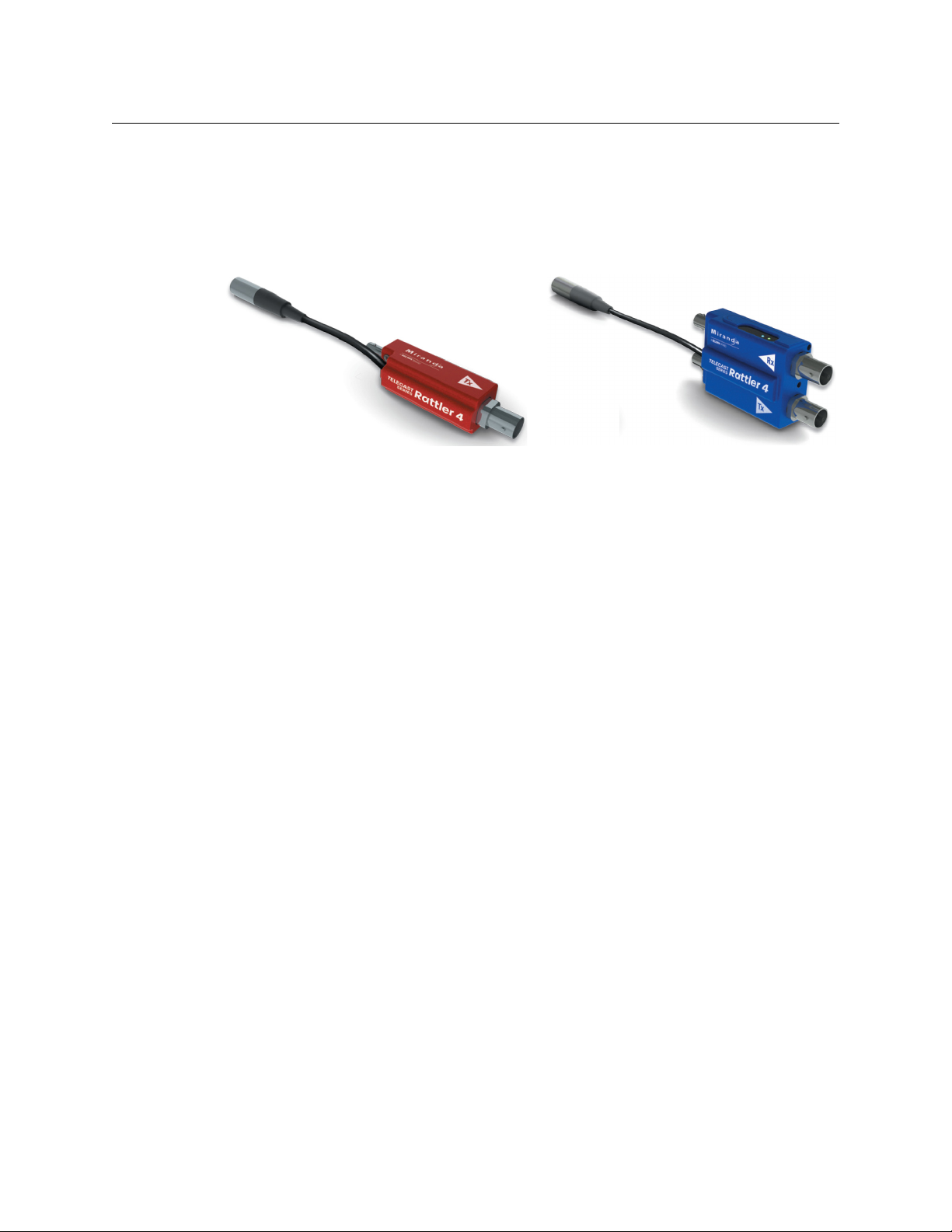
The Rattler 4 is a miniature HD/SDI to fiber optical signal converter. The Rattler 4 TX
Transmitter unit accepts a 75 ohm coaxial input and converts it into an optical signal via a
standard ST connector. The Rattler 4 RX Receiver unit reconverts the signal back to a BNC
output.
The Rattler 4 can transmit any of the following signal types:
• 3 Gbps SMPTE 424M HD-SDI
• 1.5 Gbps SMPTE 292M HD-SDI
• 19.4 Mbps SMPTE310M
• 143 to 540 Mbps SMPTE2 59M/344M
• DVB/ASI 270 Mbps
• AES and MADI audio
• plus non-standard digital signals to 3 Gbps
Fig. 1-1: Rattler 4 TX and TR Units
The Rattler 4 is available in single and dual receiver and transmitter units as well as a dual
T
ransceiver unit.
Transmitters are available in standard 1310 wavelength, 1550 WDM wavelength, and
WDM wavelengths. All 18 standard CWDM wavelengths are available. For CWDM
C
transmitters, an appropriate CWDM multiplexer (such as Grass Valley's passive CWDM units)
should be used to combine multiple CWDM signals from CWDM Rattler 4s and other
devices. An appropriate demultiplexer should be used (such as Grass Valley's passive
CWDM units) when using Rattler 4 receivers or the Grass Valley Python or Telethon active
demultiplexers and media converters.
Physically compact at 3.2 inches in length, the
and Red for Transmitters.
All Rattler 4 units come with a permanently attached mini-XLR power connector . Power
omes from the supplied power supply or any mini-XLR jack equipped power supply
c
providing 5-16 volts VDC.
All units come with a set of power and signal LED indicators .
• The Receiver units have a four LED array to indicate signal strength.
• The Transmitter unit has a single L
ED to indicate signal presence.
units are color-coded with Blue for Receivers
2
Page 7
Rattler 4
User Guide
The Rattler 4 is fully interoperable with a wide range of Grass Valley series fiber optic
equipment as well as other manufacturers. Certain Grass Valley PicoLink accessories may be
used with the Rattler 4 units. Please see your authorized Grass Valley series dealer for more
information (seeContact Us on page 21).
About This User Guide
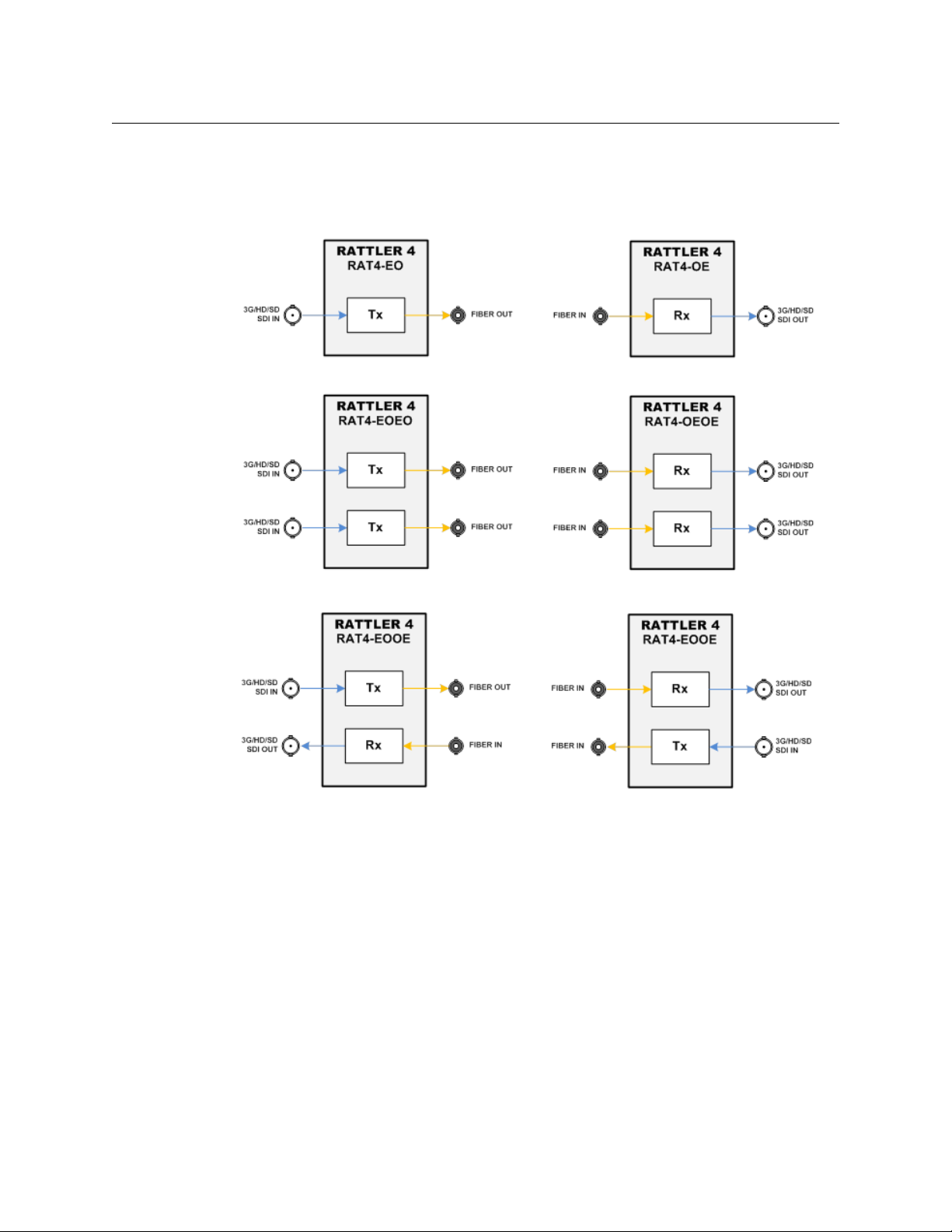
The Rattler 4 is available in five standard models:
•Single Tx
•Single Rx
•Dual Tx
•Dual Rx
•Bi-Directional Transceiver
Each of these models is described in this
accessories are also available.
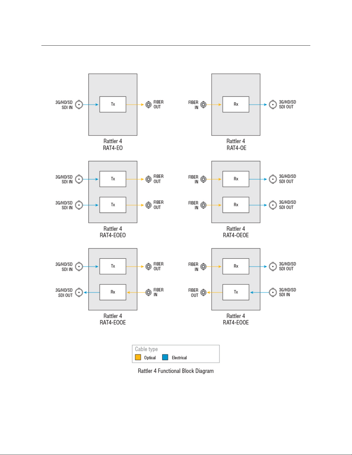
Fig. 1-2: Rattler 4 Block Diagrams
User Guide. Kits of matched pairs and various
3
Page 8
Introduction
Available Rattler 4 Models
Available Rattler 4 Models
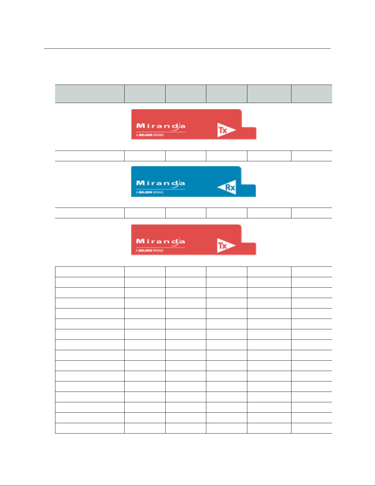
All Rattler 4 Units come with a Mini-XLR locking power cord.
BNC
Model Type
RAT4-EO-MXLR Transmitter Input Output No
RAT4-OE-MXLR Receiver Output Input No
Single Transmitter Units with CWDM
Connector
Single Transmitter Unit
Single Receiver Unit
ST
Connector
Fiber Optic
Wavelength
CWDM
RAT4-EO-1271-MXLR Transmitter Input Output Yes
RAT4-EO-1291-MXLR Transmitter Input Output Yes
RAT4-EO-1311-MXLR Transmitter Input Output Yes
RAT4-EO-1331-MXLR Transmitter Input Output Yes
RAT4-EO-1351-MXLR Transmitter Input Output Yes
RAT4-EO-1371-MXLR Transmitter Input Output Yes
RAT4-EO-1391-MXLR Transmitter Input Output Yes
RAT4-EO-1411-MXLR Transmitter Input Output Yes
RAT4-EO-1431-MXLR Transmitter Input Output Yes
RAT4-EO-1451-MXLR Transmitter Input Output Yes
RAT4-EO-1471-MXLR Transmitter Input Output Yes
RAT4-EO-1491-MXLR Transmitter Input Output Yes
RAT4-EO-1511-MXLR Transmitter Input Output Yes
RAT4-EO-1531-MXLR Transmitter Input Output Yes
RAT4-EO-1551-MXLR Transmitter Input Output Yes
RAT4-EO-1571-MXLR Transmitter Input Output Yes
4
Page 9

Rattler 4
User Guide
Model Type
BNC
Connector
ST
Connector
Fiber Optic
Wavelength
CWDM
RAT4-EO-1591-MXLR Transmitter Input Output Yes
RAT4-EO-1611-MXLR Transmitter Input Output Yes
Dual Transmitter Unit
RAT4-EOEO-A-MXLR Dual
ansmitte r
Tr
2 Inputs 2 Outputs 1310 nm No
Dual Receiver Unit
RAT4-OEOE-MXLR Dual Receiver 2 Outputs 2 Inputs Not Applicable No
Transceiver Unit
RAT4-EOOE-A-MXLR Transmitter
Receiver
Input
Output
Output
Input
1310 nm
Not Applicable
No
No
5
Page 10

Introduction
Rattler Kits
Rattler Kits
All kits come in a Injection Molded Road Case (RAT4-KIT-CASE can be ordered separately)
with two LKS-WSU power supplies.
• RAT4-KIT1-T-MXLR: consists of one RAT4-EO-A-MXLR Transmitter and one RAT4-OE-
MXLR Receiver
• RAT4-KIT2-TT-MXLR: consists of one dual RAT4-EOEO-A-MXLR Transmitter and one
dual RAT4-OEOE-MXLR Receiver
• RAT4-KIT3-TR-MXLR: consists of two RAT4-EOOE-A-MXLR Transceivers
6
Page 11

Unpacking the Rattler 4
Please consult your packing slip and purchase order to ensure that you have received all of
the expected components.
Inspect all components for scratches and other mechanical damage, and inspect the
electrical connectors for bent or damaged pins and latches. Report any missing or
damaged components to Grass Valley, a Belden Brand (see
Product Returns
In the unlikely event of damage to your Rattler 4 during shipping or delivery, take note or
any damage with the delivery or shipping service. If any component does not work
correctly out of the box, contact Grass Valley, a Belden Brand (see
If the problem cannot be remedied through a service telephone call, you will receive an
RMA number (Return of Merchandise Authorization). Please note this RMA number inside
and outside of all shipping boxes and on all documentation provided with the items to be
returned.
Rattler 4
User Guide
Product Returns on page 7).
Contact Us on page 21).
Optical Fiber Safety
• Never look directly into the end of the optic fiber while either end of the system is
operating.
• This Rattler 4 contains CDRH Class 1 laser devices. To prevent damaging your eyes,
always avoid looking directly at, or staring into, the laser light located on an optical
connector or on the end of a fiber.
• Infrared radiation (invisible to the human eye) is produced at the ST fiber connection
and at the end of any un-terminated optical fibers that are attached to this connection.
Avoid any direct exposure to the light that comes from these sources.
• Do not power up the unit if there are no fiber connectors attached to the fiber port.
• There are no manual adjustments to be made inside the Rattler 4. Do not attempt any
type of service to this instrument, other than any as instructed this User Guide. Refer all
servicing to Grass Valley, a Belden Brand.
• Always keep the Fiber Optical connectors protected when not connected. Use
protective caps if available. This protects the connector from damage and the unlikely
event of exposure to an operating optical link. Keeping the connectors protected
when the connectors are not in use will prevent dirt and dust from entering the
connector and degrading the performance of the optical link.
• You should read the Using Fiber Optics Guide for information on how to manage and
deploy your fiber optics cabling, safety precautions, tips & tricks, and recommendations
for creating complex fiber optic networks. You can find a copy of this document on the
Support portal (see
Contact Us on page 21).
7
Page 12

Introduction
Electromagnetic Compatibility
Electromagnetic Compatibility
This equipment has been tested for verification of compliance with FCC Part 15, Subpart B
requirements for Class A digital devices.
Notes
This equipment has been tested and found to comply with the limits for a
Class A digital device, pursuant to part 15 of the FCC Rules. These limits are
designed to provide reasonable protection against harmful interference
when the equipment is operated in a commercial environment.
This equipment generates, uses, and can radiate radio frequency energy and,
not installed and used in accordance with the User Guide, may cause
if
rmful interference to radio communications.
ha
Operation of this equipment in a residentia
interference in which case the user will be required to correct the
interference at their own expense.
l area is likely to cause harmful
This equipment has been tested and found to comply with the requirements of the EMC
directive 2004/108/CE:
• EN 55022 Class A radiated and conducted emissions
• EN 55024 Immunity of Information Technology Equipment
• EN 61000-3-2 Harmonic current injection
• EN 61000-3-3 Limitation of voltage changes, voltage fluctuations and flicker
• EN 61000-4-2 Electrostatic discharge immunity
• EN 61000-4-3 Radiated electromagnetic field immunity – radio frequencies
• EN 61000-4-4 Electrical fast transient immunity
• EN 61000-4-5 Surge immunity
• EN 61000-4-11 Voltage dips, short interruptions and voltage variations immunity
8
Page 13

Rattler 4 Operation
This chapter describes how the Rattler 4 system operates, including how to install the
sytem and how to read the LEDs.
Rattler 4 Single Unit Components . . . . . . . . . . . . . . . . . . . . . . . . . . . . . . . . . . . . . . . . . . . . . . . . . . . . . 10
Rattler 4 Dual Unit Operation . . . . . . . . . . . . . . . . . . . . . . . . . . . . . . . . . . . . . . . . . . . . . . . . . . . . . . . . . 12
Using the PicoLink pL-Tray to Rack Mount the Rattler 4 . . . . . . . . . . . . . . . . . . . . . . . . . . . . . . . . 13
Fiber Optical Channel Monitoring using the LED Display . . . . . . . . . . . . . . . . . . . . . . . . . . . . . . 14
9
Page 14

Rattler 4 Operation
LKS-WSU Power Supply
Pin 1: Shield
Pin 2: Ground
Pin 3: +5 VDC
Rattler 4 Single Unit Components
Rattler 4 Single Unit Components
The Rattler 4 has no user adjustable components. The LED area provides monitoring once
the connections are made and the unit is connected to power.
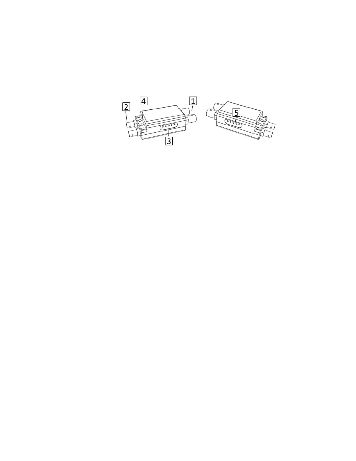
Fig. 2-1: Rattler 4 Single Unit
The Rattler 4 Single Unit features the following:
1 BNC Connector: HD/SDI Input for the Tx Unit and Output for the Rx Unit. Please see
Unpacking the Rattler 4 on page 7 for a list of supported signals.
2 ST F
3 LED Display Area
4 M
iber Connector
• The Tx unit has a two LED Display
• The Rx unit has a five LED Display
Please see below for detailed information on the LED display area.
ini-XLR Power Connector: the connector is attached permanently to the Rattler 4
Unit and can be powered by the Grass Valley LKS-WSU Universal Power Supply or by
any power supply with a Mini-XLR3F power connector. The Rattler 4 operates on 5-16
VDC.
10
Note: The Mini-XLR power connector is not compatible with previous
4-pin XLR power supplies.
Fig. 2-2: Power Supply and Connector
Page 15
LED Display Operation
Two LEDs lit indicate a signal strength
between -15 dBm and -10 dBm
Four LEDs lit indicate a signal strength
between -5 dBm and 0 dBm
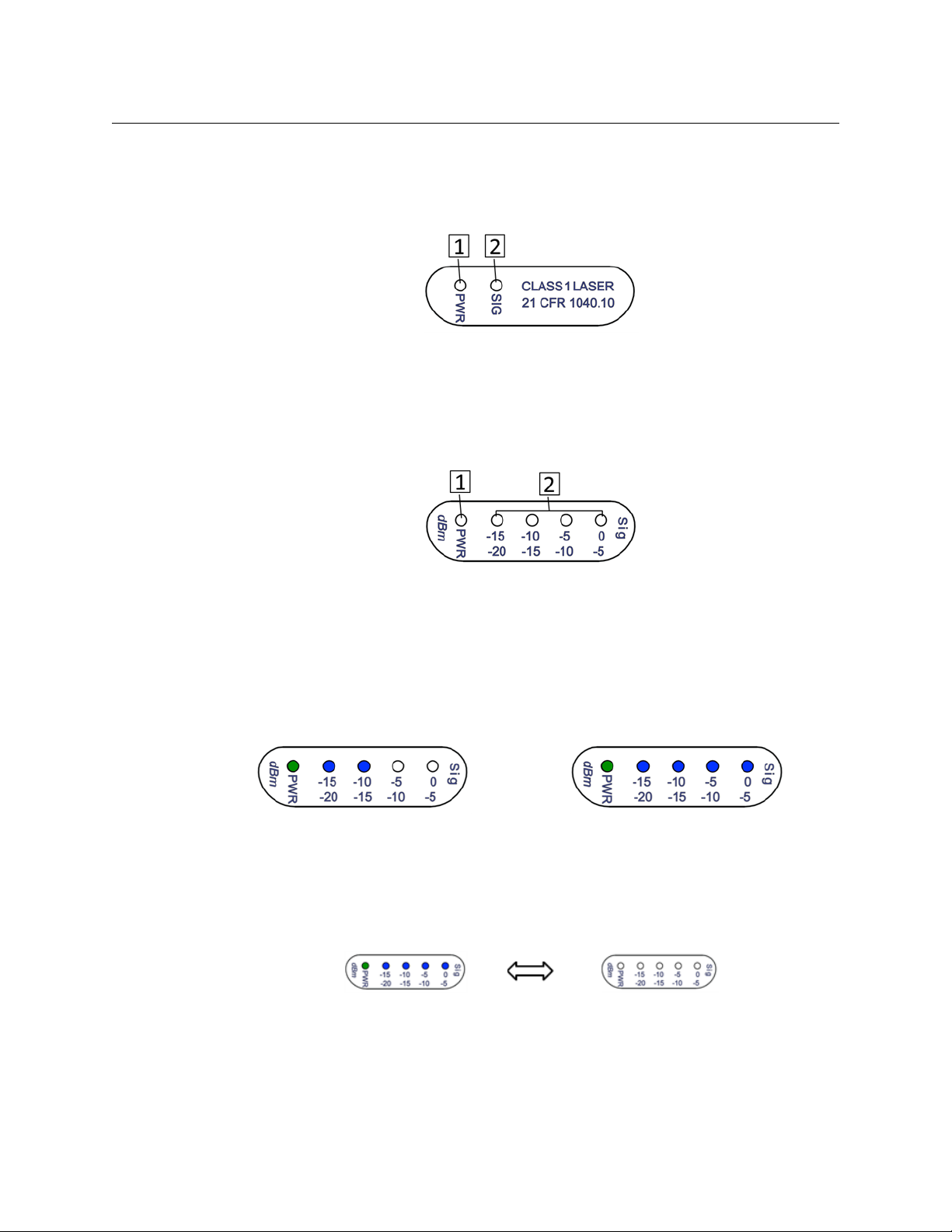
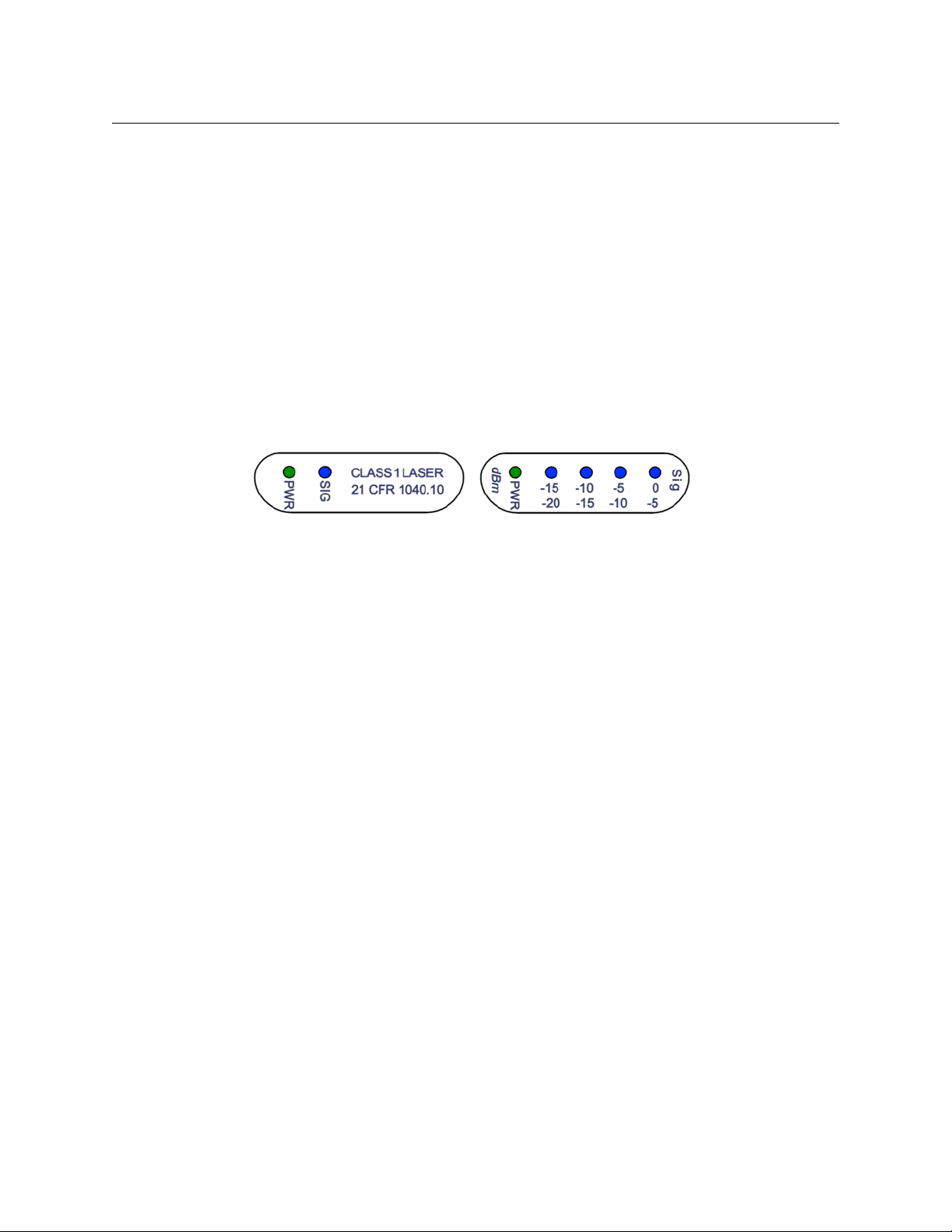
Rattler Tx Unit
1 Power LED – indicates power is connected and within 5-16 VDC range
2 SIG LED
Rattler Rx Unit
– indicates HD/SDI Signal Presence
Rattler 4
User Guide
Fig. 2-3: Rattler Tx Unit LEDs
Fig. 2-4: Rattler Rx Unit LEDs
1 Power LED – indicates power is connected and within 5-16 VDC range
2 Sig Strength LED Display – indicates Received Optical Signal Strength from -20 dBm to
0 dBM
Fiber Optic Signal Strength measurement is explained further in Fiber Optical Channel
Monitoring using the LED Display on
page 14.
See below for examples of signal strength indications.
Fig. 2-5: LED indications
The Rattler 4 will indicate a non-standard temperature reading if the LEDs begin to blink all
On and all Off.
Fig. 2-6: non-standard temperature LEDs
If the Rattler unit internal temperature drops below -30 degrees C or above 65 degress C,
the blinking LED indicator will start. At these extreme temperatures, unit performance will
be degraded or cease to function.
11
Page 16
Rattler 4 Operation
Rattler 4 Dual Unit Operation
Rattler 4 Dual Unit Operation
Rattler 4 Dual Unit operation is nearly identical to that of the single units. The dual units
have two independent LED displays, one on each side of the unit. Only one power supply is
required.
1 Two BNC connectors
• The Dual TX unit has two BNC Inputs
• The Dual RX unit has two BNC Outputs
• The TR transceiver unit has one BNC Input and one BNC Output.
2 T
wo ST connectors
• The Dual TX unit has two ST Outputs
• The Dual RX unit has two ST Inputs
• The TR transceiver unit has one ST Input and one BNC Output
3 LED Displa
• Two LEDs for TX Units
•Five LEDs for RX Units
• One of each type for Transceiver Units
4 P
ower Connection: the Pico-PA adapter allows the Rattler 4 to be used with standard
12V XLR power sources such as battery belt packs and power supplies (Mini-XLR Power
connector and cable not shown for clarity).
• LED Displa
LEDs depending on Rattler 4 model).
y
y: second LED display on side opposite from first LED diplay (five or two
Fig. 2-7: Rattler 4 Dual Unit
12
Page 17
Using the PicoLink pL-Tray to Rack Mount the Rattler 4
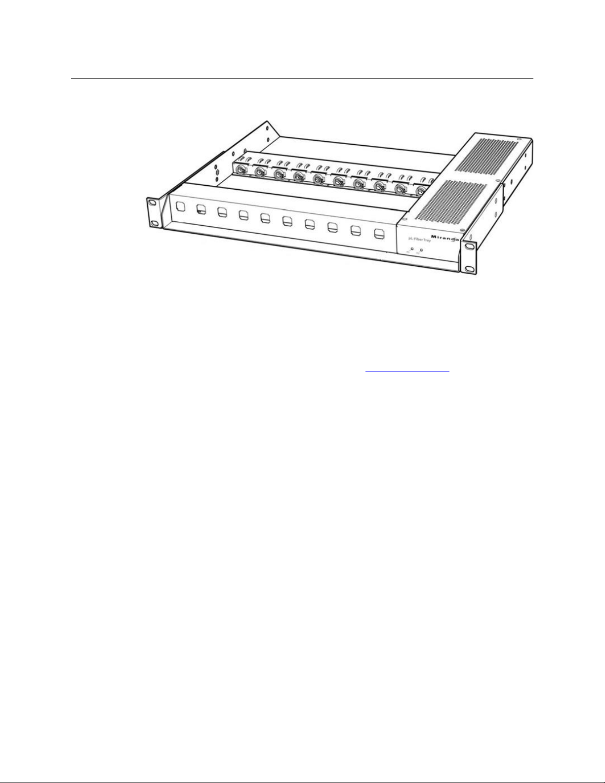
Fig. 2-8: PicoLink pL-Tray
The Rattler 4 and the Grass Valley PicoLink decoder product are the same physical size. This
allows the use of certain PicoLink accessories with the Rattler 4.
Rattler 4
User Guide
The pL-Tray is a rack-mountable unit that can hold up to 10 R
Tray can provide redundant dual power supplies to ensure continuous Rattler operation.
Please see the Grass Valley, a Belden Brand web site
information or contact your authorized Grass Valley reseller.
www.miranda.com for additional
attler 4 single units. The pL-
13
Page 18

Rattler 4 Operation
Fiber Optical Channel Monitoring using the LED Display
Fiber Optical Channel Monitoring using the LED Display
The Rattler 4 Rx receiver units provide direct digital readout of the Fiber Optic Link signal
strength for signals received at the unit. This readout is presented in 5 dBm ranges of dBm
Both the dB or decibel and the dBm or decibel referenced to one milliwatt.
units .
The decibel (dB) is a logarithmic unit of measurement that expresses the magnitude of a
physical quantity (usually power or intensity) relative to a specified or implied reference
level. Since it expresses a ratio of two quantities with the same unit, it is a dimensionless,
relative unit. A decibel is 1/10 of a bel, a seldom-used unit. Typically dB has been employed
in Audio Measurement and Fiber Optics among many uses.
Proper measurement of signal strength requires an absolute measurement and the dBm
provides this measurement. Since it is referenced to the milliwatt, it is an absolute unit,
used when measuring absolute power. By comparison, the decibel (dB) is used for
quantifying the ratio between two values, such as signal-to-noise ratio
The Rattler 4 operates within a defined range of Fiber Optic Link signal strength. The
minimum recommended signal strength is -20 dBm or better. Typically the system should
operate at levels between -8 dBm and -20 dBm.
the number of connections between the two Rattler 4 units. Each connection, interconnect,
or patch cable will produce a measurable signal loss that will contribute to decreasing the
overall link optical loss margin and attainable distance.
Cable length affects signal strength as does
The maximum fiber distance is defined by the optical loss margin. The RX signal must be 20 dBm or better. Losses on single mode fiber are approximately 0.5 dB/km or less. CWDM’s
account for about 5 dBm of loss per pair and must be considered when computing your link
loss budget.
14
Page 19

Best Practices
This chapter presents the Best Practices with the equipment as well as a Troubleshooting
section.
Best Practices . . . . . . . . . . . . . . . . . . . . . . . . . . . . . . . . . . . . . . . . . . . . . . . . . . . . . . . . . . . . . . . . . . . . . . . . 16
Troubleshooting . . . . . . . . . . . . . . . . . . . . . . . . . . . . . . . . . . . . . . . . . . . . . . . . . . . . . . . . . . . . . . . . . . . . . 16
Block Diagram . . . . . . . . . . . . . . . . . . . . . . . . . . . . . . . . . . . . . . . . . . . . . . . . . . . . . . . . . . . . . . . . . . . . . . . 17
15
Page 20
Best Practices
Tx Unit Rx Unit
Best Practices
Best Practices
• Protect the Fiber Optic Cable and the Fiber Optic Connectors using the connector
• Al
• You should read the Using
• Once the system is set up and running, check the sy
• Because the system is digital, the Signal Str
covers provided with theRattler 4.
ways keep these connectors protected unless they are being connected.
Fiber Optics Guide for information on how to manage and
deploy your fiber optics cabling, safety precautions, tips & tricks, and recommendations
for creating complex fiber optic networks. You can find a copy of this document on the
Support portal (see Contact Us on page 21).
stem display on the Rattler 4 for
proper optical signal levels. Connections to the Rattler 4 must be in place in order for
the LED display to function.
ength should fall within acceptable levels.
When the Signal Strength is no longer strong enough, the signal stops.
Troubleshooting
Troubleshooting any technical issues with the Rattler 4 System is similar to any piece of
television production gear with the obvious exception of the core Fiber Optic technology.
Here is a list of things to look out for and check:
• Check all your cables for any broken or bad connectors.
• Ensure that your Power Supply is connected and functioning.
• If using an external battery, ensure that it is fully charged.
• If you cannot resolve the problem in the field, contact support (see Contact Us on
page 21).
Fig. 3-1: Rattler 4 Optical Power Indicators
16
Page 21
Block Diagram
Rattler 4
User Guide
Fig. 3-2: Rattler 4 Functional Block Diagram
17
Page 22

Best Practices
Block Diagram
18
Page 23

Specifications
Video
Transmission Method....................................................................................................... Digital
Input Level ............................................................................................800 mV (Peak To Peak)
Input Impedance .......................................................................................................... 75 Ohms
Coaxial Equalization at 2.97 Gbps .........................3G 100m; HD 300m Belden 1694A
Output Impedance ...................................................................................................... 75 Ohms
Bit-Error Rate at -22 dBm ................................................................................................... 10
Jitter (pathological data pattern)................................................................................ <0.2 UI
Rise/fall times................................................................................................................... <120 ps
Transmission
Operating Wavelength..............................................................1310 nm 1550 nm (WDM)
........................................................................................................... or 1270-1610 nm (CWDM)
Coaxial video connector I/O ...............................................................................................BNC
Optical Connector ......................................................................................................................ST
Optical Source ...................................................................Laser Diode (FP or CWDM DFB)
Optical Detector................................................................................................... PIN-TIA diode
Transmitter Output................................................... -7 (1330, 155nm), +3 dBm (CWDM)
Receiver Sensitivity ........................................................................................................-22 dBm
Link Margin................... typically 15dB / 20km (1330, 155nm), 25dB/50km (CWDM)
Fiber Type .................................................................................................................Single-Mode
-11
Mechanical/Environmental
Dimensions (WxHxD) ....................................................................................................................
Single Units............................................................................................... 0.75 x 0.75 x 3.2 in
Dual Units.....................................................................................................0.75 x 1.5 x 3.2 in
Weight (not including power supply)............................................................................. 3 oz
Input voltage..................................................................................................................5-16 VDC
Power Connector.......................................................................Plug replaceable, mini-XLR
...........................................................................3m (Switchcraft Tini Q-G TA3MX or similar)
Power consumption (typical) ....................................................................................600 mW
Indicators.......................................................................... Power, signal, link, optical power
Temperature Range ...............................................................................................-25° to 55 °C
Humidity Range ..........................................................................0 to 95 % non-condensing
Compliance
Laser Safety.............................................................................................................. Class 1 Laser
EMI/RFI....................................................................................Complies with IEC/EN 60825-1
Certifications .........................................................................................................................RoHS
19
Page 24

Specifications
20
Page 25

Grass Valley Technical Support
For technical assistance, please contact the Grass Valley Technical Support center nearest
you:
Contact Us
Americas
Office hours: 9:00 a.m. – 9:00 p.m. (EST)
Telephone: 1-800-224-7882
Fax: +1 514 335 1614
E-mail: support@miranda.com
Europe, Middle East, Africa, UK
Office hours: 9:00 a.m. – 6:00 p.m. (GMT)
Telephone: +44 118 952 3444
Fax: +44 118 952 3401
E-mail: eurotech@miranda.com
France
Office hours: 9:00 a.m. – 5:00 p.m. (GMT+1)
Telephone: +33 1 55 86 87 88
Fax: +33 1 55 86 00 29
E-mail: eurotech@miranda.com
Corporate Head Office
Asia
Office hours: 9:00 a.m. – 6:00 p.m. (GMT+8)
Telephone: +852 2539 6987
Fax: +852 2539 0804
E-mail: asiatech@miranda.com
China
Office hours: 9:00 a.m. – 6:00 p.m. (GMT+8)
Telephone: +86 10 5873 1814
E-mail: asiatech@miranda.com
Malaysia
Telephone: +60 3 2247 1808
EMERGENCY After Hours (Global)
Toll Free: 1-800-224-7882 (US and Canada)
Telephone: +1 514 333 1772
Grass Valley
3499 Douglas-B.-Floreani
St-Laurent, Quebec H4S 2C6
Canada
Telephone: +1 514 333 1772
Fax: +1 514 333 9828
Web: www.miranda.com
 Loading...