

Page 1

Python 3G User Guide
M4040-9900-102
24 July 2014
Page 2

Notices
Copyright & Trademark Notice
Copyright © 2006–2014, Grass Valley. All rights reserved.
Belden, Belden Sending All The Right Signals, and the Belden logo are trademarks or
registered trademarks of Belden Inc. or its affiliated companies in the United States and
other jurisdictions. Grass Valley, Python 3G are trademarks or registered trademarks of
Grass Valley. Belden Inc., Grass Valley, and other parties may also have trademark rights in
other terms used herein.
Terms and Conditions
Please read the following terms and conditions carefully. By using Python 3G
documentation, you agree to the following terms and conditions.
Grass Valley, a Belden Brand (“Grass Valley”) hereby grants permission and license to owners
of Python 3G to use their product manuals for their own internal business use. Manuals for
Grass Valley products may not be reproduced or transmitted in any form or by any means,
electronic or mechanical, including photocopying and recording, for any purpose unless
specifically authorized in writing by Grass Valley.
A Grass Valley manual may have been revised to reflect changes made to the product
during its manufacturing life. Thus, different versions of a manual may exist for any given
product. Care should be taken to ensure that one obtains the proper manual version for a
specific product serial number.
Information in this document is subject to change without notice and does not represent a
commitment on the part of Grass Valley.
Warranty information is available in the Support section of the Grass Valley Web site
(www.miranda.com).
Title Python 3G User Guide
Part Number M4040-9900-102
Revision 24 July 2014
ii
Page 3

Table of Contents
1 About Python 3G . . . . . . . . . . . . . . . . . . . . . . . . . . . . . . . . . . . . . . . 1
About the Python 3G System . . . . . . . . . . . . . . . . . . . . . . . . . . . . . . . . . . . . . . . . . . . . . . . . . . . . . . 2
Fiber Cable Overview . . . . . . . . . . . . . . . . . . . . . . . . . . . . . . . . . . . . . . . . . . . . . . . . . . . . . . . . . . 3
Unpacking the Python 3G . . . . . . . . . . . . . . . . . . . . . . . . . . . . . . . . . . . . . . . . . . . . . . . . . . . . .4
Product Returns . . . . . . . . . . . . . . . . . . . . . . . . . . . . . . . . . . . . . . . . . . . . . . . . . . . . . . . . . . . . . . . 4
Safety and Fiber Optic Systems . . . . . . . . . . . . . . . . . . . . . . . . . . . . . . . . . . . . . . . . . . . . . . . . . . . . 5
Optical Fiber Safety. . . . . . . . . . . . . . . . . . . . . . . . . . . . . . . . . . . . . . . . . . . . . . . . . . . . . . . . . . . . 5
FCC Part A Manual Notice. . . . . . . . . . . . . . . . . . . . . . . . . . . . . . . . . . . . . . . . . . . . . . . . . . . . . . 5
2 Hardware and Block Diagrams . . . . . . . . . . . . . . . . . . . . . . . . . . 7
Available Models . . . . . . . . . . . . . . . . . . . . . . . . . . . . . . . . . . . . . . . . . . . . . . . . . . . . . . . . . . . . . . . . . . 8
Block Diagrams. . . . . . . . . . . . . . . . . . . . . . . . . . . . . . . . . . . . . . . . . . . . . . . . . . . . . . . . . . . . . . . . . . .11
PY3-AA00-ST4. . . . . . . . . . . . . . . . . . . . . . . . . . . . . . . . . . . . . . . . . . . . . . . . . . . . . . . . . . . . . . . .11
PY3-AA00-ST8 /PY3-RR00-ST8. . . . . . . . . . . . . . . . . . . . . . . . . . . . . . . . . . . . . . . . . . . . . . . . .12
PY3-AR00-ST8 . . . . . . . . . . . . . . . . . . . . . . . . . . . . . . . . . . . . . . . . . . . . . . . . . . . . . . . . . . . . . . . .13
PY3-AAR0-ST12 / PY3-RRA0-ST12 . . . . . . . . . . . . . . . . . . . . . . . . . . . . . . . . . . . . . . . . . . . . .14
PY3-AAAA-ST16 / PY3-RRRR-ST16 . . . . . . . . . . . . . . . . . . . . . . . . . . . . . . . . . . . . . . . . . . . . .15
PY3-AARR-ST16 . . . . . . . . . . . . . . . . . . . . . . . . . . . . . . . . . . . . . . . . . . . . . . . . . . . . . . . . . . . . . .16
PY3-G000-W41/PY3-R000-W41. . . . . . . . . . . . . . . . . . . . . . . . . . . . . . . . . . . . . . . . . . . . . . . .17
PY3-GH00-W8/PY3-RR00-W8. . . . . . . . . . . . . . . . . . . . . . . . . . . . . . . . . . . . . . . . . . . . . . . . . .18
PY3-GR00-W8/PY3-HR00-W8. . . . . . . . . . . . . . . . . . . . . . . . . . . . . . . . . . . . . . . . . . . . . . . . . .19
PY3-GHJK-W16/PY3-RRRR-W8. . . . . . . . . . . . . . . . . . . . . . . . . . . . . . . . . . . . . . . . . . . . . . . . .20
PY3-GHRR-W8W8. . . . . . . . . . . . . . . . . . . . . . . . . . . . . . . . . . . . . . . . . . . . . . . . . . . . . . . . . . . . .21
PY3-GHRR-W16/PY3-JKRR-W16 . . . . . . . . . . . . . . . . . . . . . . . . . . . . . . . . . . . . . . . . . . . . . . .22
3 Python 3G Components. . . . . . . . . . . . . . . . . . . . . . . . . . . . . . . . 23
Python 3G Models . . . . . . . . . . . . . . . . . . . . . . . . . . . . . . . . . . . . . . . . . . . . . . . . . . . . . . . . . . . . . . . .24
Python 3G Front Panel. . . . . . . . . . . . . . . . . . . . . . . . . . . . . . . . . . . . . . . . . . . . . . . . . . . . . . . . . . . .25
Power and Display Panel. . . . . . . . . . . . . . . . . . . . . . . . . . . . . . . . . . . . . . . . . . . . . . . . . . . . . .25
Python 3G Transmitter. . . . . . . . . . . . . . . . . . . . . . . . . . . . . . . . . . . . . . . . . . . . . . . . . . . . . . . .25
Area A – SDI/DATA IN . . . . . . . . . . . . . . . . . . . . . . . . . . . . . . . . . . . . . . . . . . . . . . . . . . . . . . . . 26
Python 3G Receiver. . . . . . . . . . . . . . . . . . . . . . . . . . . . . . . . . . . . . . . . . . . . . . . . . . . . . . . . . . .26
Area A – SDI/DATA OUT . . . . . . . . . . . . . . . . . . . . . . . . . . . . . . . . . . . . . . . . . . . . . . . . . . . . . .27
Python 3G Transceiver. . . . . . . . . . . . . . . . . . . . . . . . . . . . . . . . . . . . . . . . . . . . . . . . . . . . . . . .28
Area A – SDI/DATA IN . . . . . . . . . . . . . . . . . . . . . . . . . . . . . . . . . . . . . . . . . . . . . . . . . . . . . . . . 28
Area B – SDI/DATA OUT . . . . . . . . . . . . . . . . . . . . . . . . . . . . . . . . . . . . . . . . . . . . . . . . . . . . . .29
Python 3G Rear Panel. . . . . . . . . . . . . . . . . . . . . . . . . . . . . . . . . . . . . . . . . . . . . . . . . . . . . . . . . . . . .30
Python 3G Transmitter Rear Panel without CWDM . . . . . . . . . . . . . . . . . . . . . . . . . . . . 30
Python 3G Transmitter Rear Panel with CWDM . . . . . . . . . . . . . . . . . . . . . . . . . . . . . . . . 30
Python 3G Receiver Rear Panel without CWDM . . . . . . . . . . . . . . . . . . . . . . . . . . . . . . . 30
Python 3G Receiver Rear Panel with CWDM . . . . . . . . . . . . . . . . . . . . . . . . . . . . . . . . . . . 31
iii
Page 4

Table of Contents
Python 3G Transceiver Rear Panel without CWDM . . . . . . . . . . . . . . . . . . . . . . . . . . . . 31
Python 3G Transceiver Rear Panel with CWDM . . . . . . . . . . . . . . . . . . . . . . . . . . . . . . . . 31
Python 3G Units with CWDM and Fiber Capability (Dual Input/Output). . . . . . . . .32
Python 3G Rear Panel Operation . . . . . . . . . . . . . . . . . . . . . . . . . . . . . . . . . . . . . . . . . . . . . . . . . .34
Area A - Rear Panel Power Connectors . . . . . . . . . . . . . . . . . . . . . . . . . . . . . . . . . . . . . . . .34
Redundant Power Supply Usage . . . . . . . . . . . . . . . . . . . . . . . . . . . . . . . . . . . . . . . . . . . . . 34
Area B – CAN BUS Connector . . . . . . . . . . . . . . . . . . . . . . . . . . . . . . . . . . . . . . . . . . . . . . . . .35
Area C – The ST Fiber Connectors . . . . . . . . . . . . . . . . . . . . . . . . . . . . . . . . . . . . . . . . . . . . .35
Power Connector Wiring. . . . . . . . . . . . . . . . . . . . . . . . . . . . . . . . . . . . . . . . . . . . . . . . . . . . . .35
Fiber ADAP Power Supplies . . . . . . . . . . . . . . . . . . . . . . . . . . . . . . . . . . . . . . . . . . . . . . . . . . . . . . .36
4 Python 3G Operation . . . . . . . . . . . . . . . . . . . . . . . . . . . . . . . . . . 37
Fiber Optical Channel Monitoring . . . . . . . . . . . . . . . . . . . . . . . . . . . . . . . . . . . . . . . . . . . . . . . . .38
Using the Python 3G Optical Measurement Display . . . . . . . . . . . . . . . . . . . . . . . . . . . . . . . .39
Python 3G Optical Measurement Display . . . . . . . . . . . . . . . . . . . . . . . . . . . . . . . . . . . . . .39
Condition 1: No Optical Link . . . . . . . . . . . . . . . . . . . . . . . . . . . . . . . . . . . . . . . . . . . . . . . . . 40
Condition 2 – Optical Link good but no SDI data present.. . . . . . . . . . . . . . . . . . . . . . 40
Condition 3 - Active usable optical link with SDI Data . . . . . . . . . . . . . . . . . . . . . . . . . 40
System Firmware Display . . . . . . . . . . . . . . . . . . . . . . . . . . . . . . . . . . . . . . . . . . . . . . . . . . . . .41
Technical Information Display . . . . . . . . . . . . . . . . . . . . . . . . . . . . . . . . . . . . . . . . . . . . . . . .41
Best Practices . . . . . . . . . . . . . . . . . . . . . . . . . . . . . . . . . . . . . . . . . . . . . . . . . . . . . . . . . . . . . . . . . . . .42
Troubleshooting . . . . . . . . . . . . . . . . . . . . . . . . . . . . . . . . . . . . . . . . . . . . . . . . . . . . . . . . . . . . . . . . .42
5 Understanding Python 3G Model Numbers. . . . . . . . . . . . . . 43
Part Numbers . . . . . . . . . . . . . . . . . . . . . . . . . . . . . . . . . . . . . . . . . . . . . . . . . . . . . . . . . . . . . . . . . . . .44
Part Number Card Options. . . . . . . . . . . . . . . . . . . . . . . . . . . . . . . . . . . . . . . . . . . . . . . . . . . .44
Fiber I/O Cards . . . . . . . . . . . . . . . . . . . . . . . . . . . . . . . . . . . . . . . . . . . . . . . . . . . . . . . . . . . . . . .45
Example Python 3G Models . . . . . . . . . . . . . . . . . . . . . . . . . . . . . . . . . . . . . . . . . . . . . . . . . . . . . . .46
6 Specifications . . . . . . . . . . . . . . . . . . . . . . . . . . . . . . . . . . . . . . . . . 47
iv
Page 5

About Python 3G
This chapter provides an overview of the Python 3G and includes the safety and warranty
information about it.
About the Python 3G System . . . . . . . . . . . . . . . . . . . . . . . . . . . . . . . . . . . . . . . . . . . . . . . . . . . . . . . . . . 2
Safety and Fiber Optic Systems . . . . . . . . . . . . . . . . . . . . . . . . . . . . . . . . . . . . . . . . . . . . . . . . . . . . . . . . 5
1
Page 6
About Python 3G
About the Python 3G System
About the Python 3G System
The Python 3G transmitter multiplexes a number of HD/SDI signals into a fiber optic
transport stream. The number of signals can be 4, 8, 12, or 16 – always in multiples of four.
Similarly, the Python 3G receiver de-multiplexes a corresponding number of fiber optic
signals into HD/SDI.
The method of fiber optic signal transmission can use one-for-one pass through conversion
of each HD/SDI signal or CWDM (course wavelength division multiplexing) for up to 16
HD/SDI signals combined into a signal fiber optic cable.
In addition to Python 3G transmitter and receiver models, Transceivers are also available
which allow various combinations of transmit and receive in the same unit. Please see
Available Models on page 8 for the model list.
Python 3G units accept electrical digital signals (via BNC), ranging from 19.4 Mbps up to
3Gbps-uncompressed HD/SDI.
Along with LEDs to indicate the presence of an HD/SDI signal at each BNC input and output,
the Python 3G features an integrated optical power meter for monitoring the received
power for each optical HD/SDI signal. Fiber optical power is measured only at the receiver
end of the signal path.
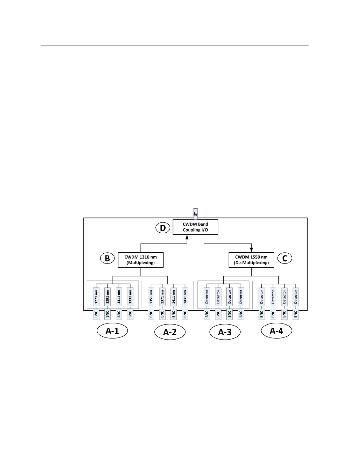
Figure 1-1 is a conceptual overview of an example Python 3G signal path.
Fig. 1-1: Python 3G Conceptual Overview
The Python 3G also features dual 12-18 VDC power inputs for electrical redundancy. Up to
3Gbps is supported on each optical channel.
The Python 3G handles a wide range of digital video rates. Supported formats include:
• 3 Gb/s HD/SDI: SMPTE 424M
• 1.5 Gb/s HD/SDI: SMPTE 292M
• 143 Mb/s: SMPTE 259M
2
Page 7
Python 3G
User Guide
• 270 Mb/s DVB/ASI (re-clocked)
• 19.4 Mb/s ATSC: SMPTE 310M
• Non-standard digital signals to 3 Gb/s
The unit is interoperable with industry standard optical HD/SDI signals to/from other
equipment, such as Rattler™, Diamondback™, SHED™, HDX™, and Viper™ series frames and
modules, as well as other manufacturers' routers, DAs, etc.
The Python 3G has four Input/Output card positions that can either convert incoming
SDI/Data BNC signals into Fiber Optic signals or can detect received Fiber Optic signals and
convert them to SDI/Data. Each position handles four channels
In the above example the two card positions A-1 and A-2 are transmitter cards. Slot A-1
handles 1310 nm low range signals and slot A-2 handles 1310 nm high range signals.
Please see Understanding Python 3G Model Numbers on page 43 for a list of all of the
available I/O cards.
P os i t i o n s A - 3 a n d A- 4 e a c h h a v e a fo u r c h an n e l d e te c t o r c ar d t h a t c o n v er t s t he i n c o m in g
de-multiplexed fiber optic feed into individual SDI/Data signals.
The eight input signals are multiplexed (B) and sent to the CWDM Band Coupling I/O card
(D). This I/O card manages on a single ST Fiber Connector the eight outgoing and eight
incoming Fiber Optic signals. 16 signals are coupled on to a single Fiber I/O. The band
coupler combines 1310 nm and 1550 nm ranges into a single Fiber Optic signal.
The incoming eight Fiber signals are decoupled, de-multiplexed (C) and sent to the
Detector cards for conversion to SDI/Data.
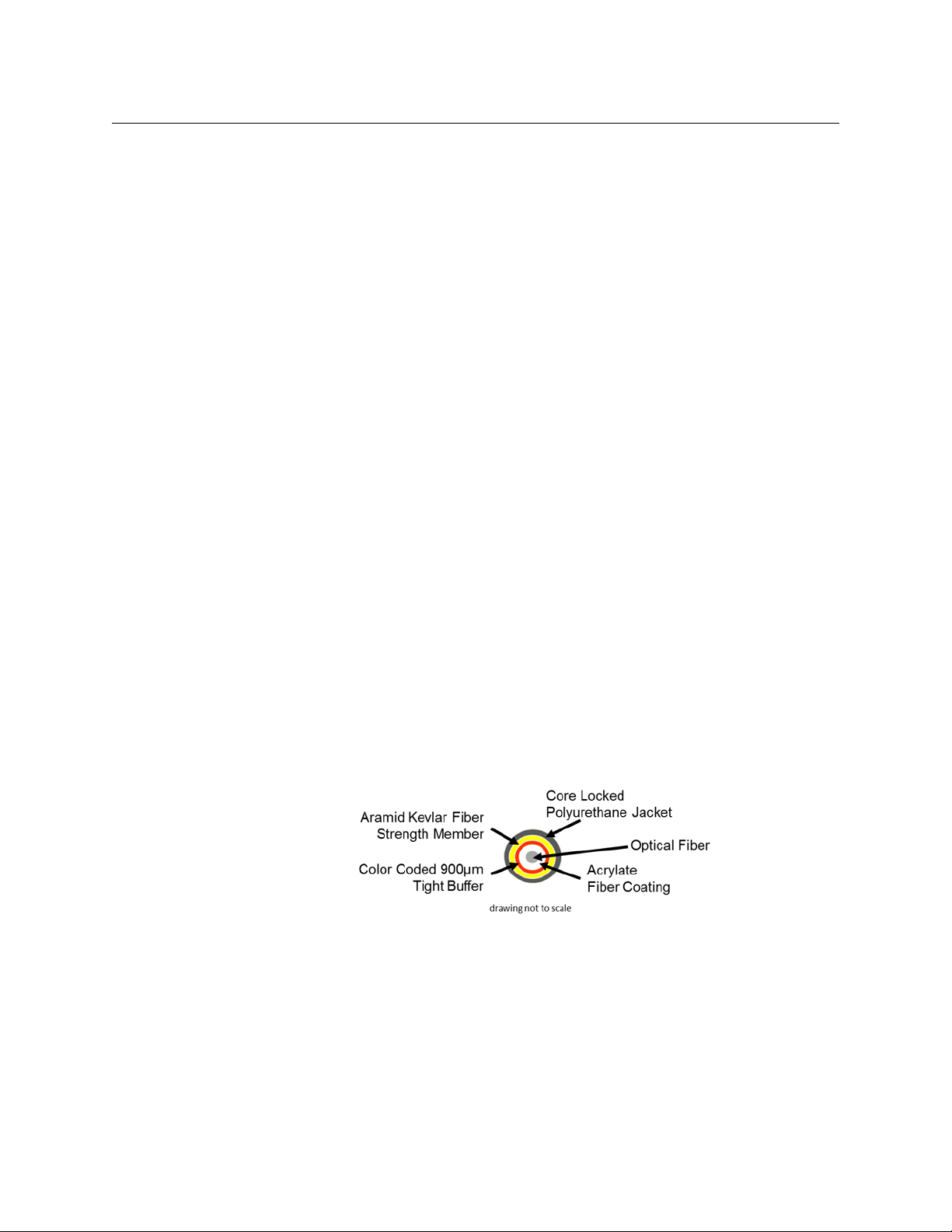
Fiber Cable Overview
Fiber Optics and Fiber Optic Cable are the core technologies at the heart of the Python 3G
System. The Python 3G features the ability to multiplex and de-multiplex a variety of video,
audio, and data signals so that they can be carried over a thin strand of Fiber Optic cable for
long distances. The specific theory and operation of Fiber Optics is beyond the scope of
this document.
Fig. 1-2: Single Mode Fiber Optic Cable Cross-Section (Illustrative Only)
3
Page 8

About Python 3G
Unpacking the Python 3G
Unpacking the Python 3G
Please consult your packing slip and purchase order to ensure that you have received all of
the expected components.
Inspect all components for scratches and other mechanical damage, and inspect the
electrical connectors for bent or damaged pins and latches. Report any missing or
damaged components to Fiber Solutions (see Product Returns on page 4).
Leave the protective caps on the optical connectors whenever the fiber is disconnected.
Product Returns
In the unlikely event of damage to your Python 3G during shipping or delivery, take note of
any damage with the delivery or shipping service. If any component does not work
correctly out of the box, please contact Grass Valley Fiber Solutions service (Contact Us on
page 49).
If the problem cannot be remedied through a service telephone call,you will receive an
RMA number (Return of Merchandise Authorization). Please note this RMA number inside
and outside of all shipping boxes and on all documentation provided with the items to be
returned.
4
Page 9

Safety and Fiber Optic Systems
Optical Fiber Safety
Never look directly into the end of the optic fiber while either end of the system is
operating.
This Python 3G contains CDRH Class 1 laser devices. To prevent damaging your eyes, always
avoid looking directly at, or staring into, the laser light located on an optical connector or
on the end of a fiber.
Infrared radiation is produced at the fiber connection port on the rear of the TX units and at
the end of any un-terminated optical fibers that are attached to this port. Avoid any direct
exposure to the light that comes from these sources.
Do not power up the unit if there are no fiber cables connected to the fiber port.
There are no manual adjustments to make inside the Python 3G. Do not attempt any type
of service on this instrument, other than any procedures as instructed in this Guide. Refer all
servicing to the Fiber Solutions division of Grass Valley (see Contact Us on page 49).
Always use cable connector caps when the cables are not connected. This protects the
connector from damage and the unlikely event of exposure to an operating optical link.
Keeping the caps in place when the connectors are not in use will prevent dirt and dust
from entering the connector and degrading the performance of the optical link.
Python 3G
User Guide
FCC Part A Manual Notice
ThisequipmenthasbeentestedandfoundtocomplywiththelimitsforaClassAdigital
device,pursuanttopart15oftheFCCrules.Theselimitsaredesignedtoprovide
reasonableprotectionagainstharmfulinterferencewhentheequipmentisoperatedina
commercialenvironment.Thisequipmentgenerates,uses,and
frequency(RF)energy.IfnotinstalledandusedinaccordancewiththisUserGuide,this
equipmentmaycauseharmfulinterferencetoradiocommunications.
canradiateradio
5
Page 10

About Python 3G
FCC Part A Manual Notice
6
Page 11

Hardware and Block Diagrams
This chapter lists the models available with the Python 3G and lists the block diagrams of
these models.
Available Models . . . . . . . . . . . . . . . . . . . . . . . . . . . . . . . . . . . . . . . . . . . . . . . . . . . . . . . . . . . . . . . . . . . . . . 8
Block Diagrams . . . . . . . . . . . . . . . . . . . . . . . . . . . . . . . . . . . . . . . . . . . . . . . . . . . . . . . . . . . . . . . . . . . . . . 11
7
Page 12
Hardware and Block Diagrams
Available Models
Available Models
The Python 3G is available in a variety of standard models. The following list covers the
models available at the time of publication. Please see Understanding Python 3G Model
Numbers on page 43 for an explanation of how to understand Python 3G Model Numbers.
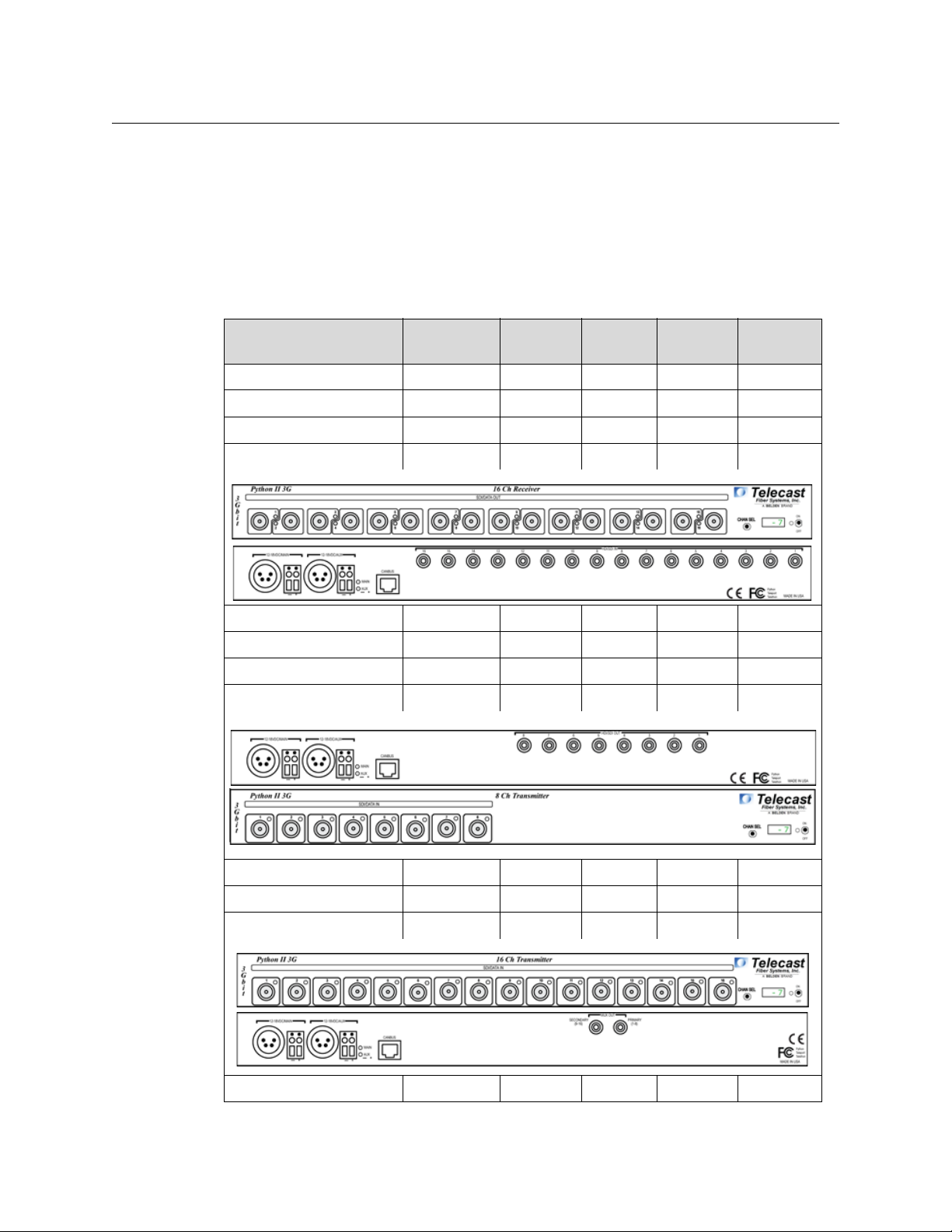
The Python 3G may contain as many as 16 HD/SDI BNC Connectors on the front panel and
as many as 16 ST Fiber Optic cable connectors on the rear panel. Illustrations of a few of the
the 29 standard models available at time of publication are included in this table.
HD/SDI
Part Number Typ e
PY3-R000-ST4 Receiver X 4 No 4
PY3-RR00-ST8 Receiver X 8 No 8
PY3-RRR0-W83W43 Receiver X 12 Yes 2
PY3-RRRR-ST16 Receiver X 16 No 16
PY3-RRRR-W16 Receiver X 16 Yes 1
PY3-RRRR-X16 Receiver X 16 Yes 2
PY3-A000-ST4 Transmitter 4 X No 4
PY3-AA00-ST8 Transmitter 8 X No 8
Tra nsm it
HD/SDI
Receive
CWDM
Equipped
Number of
Fibers
PY3-GHJ0-W83W43 Transmitter 12 X Yes 1
PY3-AAAA-ST16 Transmitter 16 X No 16
PY3-GHJK-W16 Transmitter 16 X Yes 1
PY3-GHJK-D16 Transmitter 16 X Yes 2
8
Page 13
Python 3G
User Guide
Part Number Typ e
HD/SDI
Tra nsm it
HD/SDI
Receive
CWDM
Equipped
Number of
Fibers
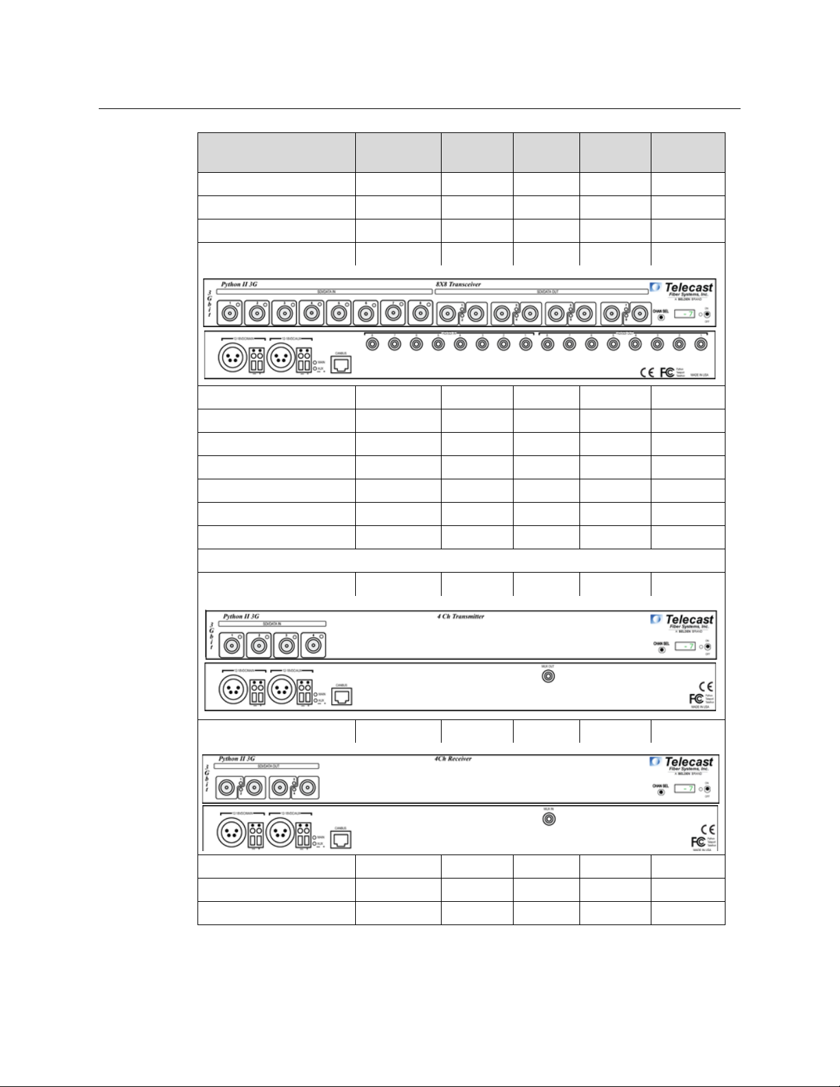
PY3-GHJR-W16 Transceiver 12 4 Yes 1
PY3-GHGR-W8W8 Transceiver 12 4 Yes 2
PY3-AAR0-ST12 Transceiver 8 4 No 12
PY3-AARR-ST16 Transceiver 8 8 No 16
PY3-AR00-ST8 Transceiver 4 4 No 8
PY3-HRRR-W8W8 Transceiver 4 12 Yes 2
PY3-GHRR-W8W8 Transceiver 8 8 Yes 2
PY3-A0RR-ST12 Transceiver 4 8 No 12
PY3-KRRR-W16 Transceiver 4 12 Yes 1
PY3-GR00-W8 Transceiver 4 4 Yes 1
PY3-HR00-W8 Transceiver 4 4 Yes 1
The following Python 3G Models are Operated as a Matched Pair
PY3-G000-W41 Transmitter 4 X Yes 1
PY3-R000-W41 Receiver X 4 Yes 1
PY3-GH00-W8 Transmitter 8 X Yes 1
PY3-RR00-W8 Receiver X 8 Yes 1
PY3-GHRR-W16 Transceiver 8 8 Yes 1
9
Page 14
Hardware and Block Diagrams
Available Models
Part Number Typ e
HD/SDI
Tra nsm it
HD/SDI
Receive
CWDM
Equipped
Number of
Fibers
PY3-JKRR-W16 Transceiver 8 8 Yes 1
Table. 2-1: Python 3G Available Models
10
Page 15
Block Diagrams
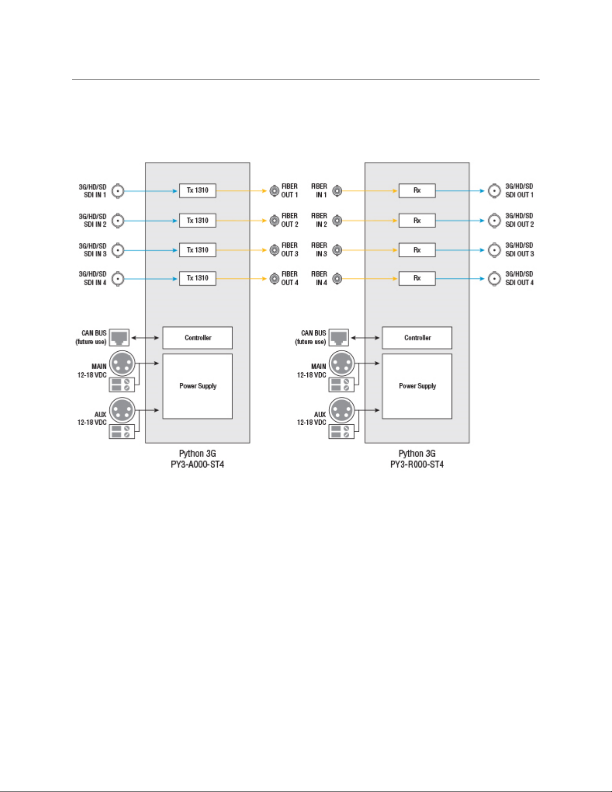
PY3-AA00-ST4
Python 3G
User Guide
Fig. 2-2: 4 Channels Python 3G on 4 Fibers Block Diagram
11
Page 16
Hardware and Block Diagrams
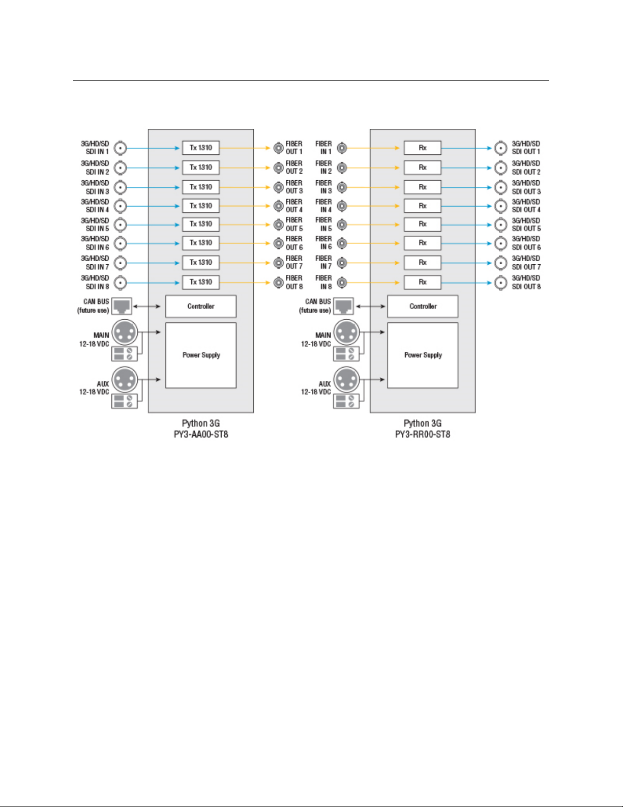
PY3-AA00-ST8 /PY3-RR00-ST8
PY3-AA00-ST8 /PY3-RR00-ST8
Fig. 2-3: 8 Channels Python 3G on 8 Fibers Block Diagram
12
Page 17

PY3-AR00-ST8
Python 3G
User Guide
Fig. 2-4: 4x4 Channels Python 3G on 8 Fibers Block Diagram
13
Page 18

Hardware and Block Diagrams
PY3-AAR0-ST12 / PY3-RRA0-ST12
PY3-AAR0-ST12 / PY3-RRA0-ST12
14
Fig. 2-5: 8x4 Channels Python 3G on 12 Fibers Block Diagram
Page 19
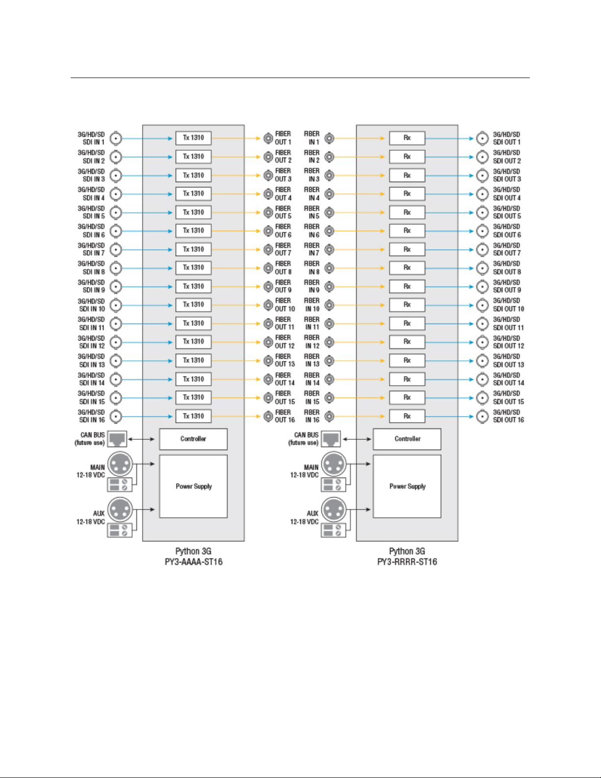
PY3-AAAA-ST16 / PY3-RRRR-ST16
Python 3G
User Guide
Fig. 2-6: 16 Channels Python 3G on 16 Fibers Block Diagram
15
Page 20

Hardware and Block Diagrams
PY3-AARR-ST16
PY3-AARR-ST16
16
Fig. 2-7: 8x8 Channels Python 3G on 16 Fibers Block Diagram
Page 21

PY3-G000-W41/PY3-R000-W41
Python 3G
User Guide
Fig. 2-8: 4 Channels Python 3G on 1 Fiber Block Diagram
17
Page 22

Hardware and Block Diagrams
PY3-GH00-W8/PY3-RR00-W8
PY3-GH00-W8/PY3-RR00-W8
Fig. 2-9: Eight Channels Python 3G on 1 Fiber Block Diagram
18
Page 23
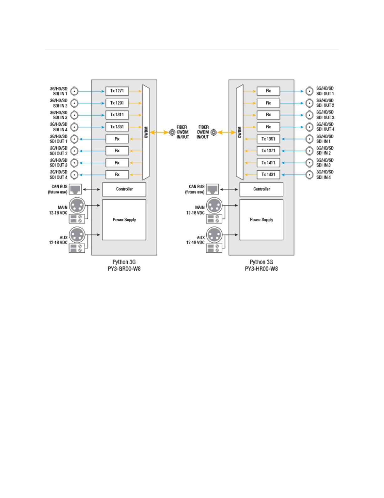
PY3-GR00-W8/PY3-HR00-W8
Python 3G
User Guide
Fig. 2-10: 4x4 Channels Python 3G on 1 Fiber Block Diagram
19
Page 24

Hardware and Block Diagrams
PY3-GHJK-W16/PY3-RRRR-W8
PY3-GHJK-W16/PY3-RRRR-W8
20
Fig. 2-11: 16 Channels Python 3G on 1 Fiber Block Diagram
Page 25

PY3-GHRR-W8W8
Python 3G
User Guide
Fig. 2-12: 8x8 Channels Python 3G on 2 Fibers Block Diagram
21
Page 26

Hardware and Block Diagrams
PY3-GHRR-W16/PY3-JKRR-W16
PY3-GHRR-W16/PY3-JKRR-W16
22
Fig. 2-13: 8x8 Channels Python 3G on 1 Fiber Block Diagram
Page 27

Python 3G Components
This chapter describes the main components of the Python 3G.
Python 3G Models . . . . . . . . . . . . . . . . . . . . . . . . . . . . . . . . . . . . . . . . . . . . . . . . . . . . . . . . . . . . . . . . . . . . 24
Python 3G Front Panel . . . . . . . . . . . . . . . . . . . . . . . . . . . . . . . . . . . . . . . . . . . . . . . . . . . . . . . . . . . . . . . . 25
Python 3G Rear Panel . . . . . . . . . . . . . . . . . . . . . . . . . . . . . . . . . . . . . . . . . . . . . . . . . . . . . . . . . . . . . . . . 30
Python 3G Rear Panel . . . . . . . . . . . . . . . . . . . . . . . . . . . . . . . . . . . . . . . . . . . . . . . . . . . . . . . . . . . . . . . . 30
23
Page 28

Python 3G Components
Python 3G Models
Python 3G Models
For illustration purposes, the following models will be included:
HD/SDI
Part Number Ty pe
PY3-R000-ST4 Receiver X 4 No 4
PY3-A000-ST4 Transmitter 4 X No 4
PY3-AR00-ST8 Transceiver 4 4 No 8
PY3-GR00-W8 Transceiver 4 4 Yes 1
Matched Pair
PY3-R000-W41 Receiver X 4 Yes 1
PY3-G000-W41 Transmitter 4 X Yes 1
Tra nsm it
HD/SDI
Receive
CWDM
Equipped
Number of
Fibers
Each model is a four channel unit. Whether your unit is a four channel unit or some multiple
up to 16 channels, the operation is identical.
The Python 3G has two main components:
• The Front panel
• The Rear panel
Fig. 3-1: Transmitter Front Panel
Fig. 3-2: Transmitter Rear Panel – Straight Through Conversion to Fiber Optical Signal
Fig. 3-3: Transmitter Rear Panel – CWDM Multiplexed Fiber Optical Signal
24
Page 29

Python 3G Front Panel
The composition of the Python 3G front panel will vary depending on whether the unit is a
receiver, transmitter or transceiver. Identify the particular Python 3G unit of interest and
then go to the page indicated.
Power and Display Panel
The Power and Display Area has four features.
• 1: CHAN SEL – scrolls the LED display through each of the Fiber Channels
• 2: Digital Display – display optical power levels, unit firmware and operating
temperature
• 3: Power Monitor LED – indicates the current Power status
• 4: ON/OFF Switch – controls power to the Python 3G unit
Python 3G
User Guide
Fig. 3-4: Power and Display Area
Forinformation on how to use the CHAN SEL switch and the digital display,see Using the
Python 3G Optical Measurement Display on page 39.
Python 3G Transmitter
The following model is the PY3-A000-ST4 which features four SDI/Data inputs converted to
four fiber optic signals. The number of BNC connectors corresponds to the type model: 4, 8,
12, or 16 inputs.
The front panel is identical to the similar CWDM equipped model with a single fiber output.
The Python 3G Receiver Front Panel has two features:
• A - SDI/Data In - see Area A – SDI/DATA IN on page 26.
• B - Power & Display Area - see Power and Display Panel on page 25.
Fig. 3-5: Python 3G Transmitter Front Panel
25
Page 30

Python 3G Components
Python 3G Receiver
Area A – SDI/DATA IN
The Python 3G Transmitter has four SDI/DATA In BNC Connectors. All four inputs operate
identically,but CWDM models are multiplexed for transmission on the fiber output of the
unit for demultiplexing to the four SDI outputs on the receiving unit. On pass-through
models, conversion to fiber optical signal occurs individually and four Fiber Optic optic
outputs are available on the rear panel.
The SDI/DATA connections can carry a variety of Baseband and Data type signals (see
Specifications on page 47 for a list).
Each input has an LED monitor that indicates the following:
• Green: SDI signal present
• Unlit : Nothing connected
Fig. 3-6: SDI/DATA Input ports
Python 3G Receiver
The following model is the PY3-R000-ST4 whichfeatures four ST fiber inputs converted to
four SDI/Data BNC outputs. The number of BNC connectors corresponds to the type model:
4, 8, 12, or 16 outputs.
The front panel is identical to the similar CWDM equipped model with a single fiber input.
The Python 3G Receiver Front Panel has two features:
• A - SDI/Data Out - see Area A – SDI/DATA OUT on page 27.
• B - Power & Display Area - see Power and Display Panel on page 25.
Fig. 3-7: Python 3G Front Panel
26
Page 31

Python 3G
User Guide
Area A – SDI/DATA OUT
Fig. 3-8: 4 SDI/DATA Output BNC Connectors
The Python 3G Receiver has four SDI/DATA Output BNC Connectors. All four Outputs
operate identically.
• On units without CWDM, the four outputs correspond to the four Fiber Optic inputs on
the back panel.
• For CWDM units, the four outputs are de-multiplexed from a single Fiber Optic input.
Each output has an LED monitor that indicates the following:
• Green: the Python 3G is receiving a signal for the indicated channel over the Fiber
Optic Cable and SDI signal is present.
• Alternating between Red and Green: a Fiber Optic connection is detected for the
indicated channel, but no SDI is present.
• Red: no optical connection is detected or the active optical signal has fallen below
-22 dBm
For more information on Fiber Optical measurement, see Fiber Optical Channel Monitoring
on page 38.
27
Page 32

Python 3G Components
Python 3G Transceiver
Python 3G Transceiver
Thefollowing model is the PY3-AR00-ST8 with four SDI/Data inputs and four SDI/Data
outputs. The inputs are converted to four fiber outputs and the outputs are converted from
four fiber inputs. The number of BNC connectors corresponds to the type model:
• Four receive and four transmit
• Eight receive and eight transmit
• Four receive and eight transmit
• Eightreceive and four transmit.
The front panel is identical to the similar CWDM equipped model with a single fiber input
and a single fiber output.
Fig. 3-9: Python 3G Transceiver Front Panel
The Python 3G Receiver Front Panel has three features:
• A - SDI/Data In - see Area A – SDI/DATA IN on page 28.
• B - SDI/Data Out - see Area B – SDI/DATA OUT on page 29.
• C - Power & Display Area - see Power and Display Panel on page 25.
Area A – SDI/DATA IN
Fig. 3-10: 4 SDI/DATA In BNC Connectors
The Python 3G Transceiver has four SDI/DATA In BNC Connectors. All four inputs operate
identically.For CWDM models,they are multiplexed for transmission on the fiber output of
the unit for demultiplexing to the four SDI outputs on the receiving unit. On pass-through
models, conversion to fiber optical signal occurs individually and four Fiber Optic optic
outputs are available on the rear panel.
The SDI/DATA connections can carry a variety of Baseband and Data type signals (see
Specifications on page 47 for a list).
Each input has an LED monitor that indicates the following:
• Green: SDI signal present
• Unlit: nothing connected
28
Page 33

Python 3G
User Guide
Area B – SDI/DATA OUT
Fig. 3-11: 4 SDI/DATA Output BNC Connectors
The Python 3G Transceiver has four SDI/DATA Output BNC Connectors. All four Outputs
operate identically.
• On units without CWDM, the four outputs correspond to the four Fiber Optic inputs on
the back panel.
• For CWDM units, the four outputs are de-multiplexed from a single Fiber Optic input.
Each output has an LED monitor that indicates the following:
• Green: the Python 3G is receiving a signal for the indicated channel over the
Multiplexed Fiber Optic Cable and SDI signal is present
• Alternating between Red and Green: a Fiber Optic connection is detected for the
indicated channel but no SDI is present.
• Red: no optical connection is detected or the active optical signal has fallen below
-22 dBm
29
Page 34

Python 3G Components
Python 3G Rear Panel
Python 3G Rear Panel
The composition of the Python 3G front panel will vary depending on whether the unit is a
receiver, transmitter or transceiver. It will also vary depending on whether the unit is a
CWDM unit or a one for one SDI to Fiber conversion unit.
The following sections describe the different types of Rear Panels that are available, but the
caption letters in each figure refers to the following sections:
• A - Power Connector Area - see Area A - Rear Panel Power Connectors on page 34
• B - CANBUS Connector - see Area B – CAN BUS Connector on page 35
• C - Fiber Connectors - see Area C – The ST Fiber Connectors on page 35
Python 3G Transmitter Rear Panel without CWDM
The following model is the PY3-A000-ST4 with four pass-through outputs. The number of
ST connectors corresponds to the type model: 4, 8, 12, or 16 inputs.
Fig. 3-12: Python 3G Transmitter Rear Panel without CWDM
Python 3G Transmitter Rear Panel with CWDM
The following model is the PY3-G000-W41 with a single ST input.
Fig. 3-13: Python 3G Transmitter Rear Panel with CWDM
Python 3G Receiver Rear Panel without CWDM
The following model is the PY3-R000-ST4 with four ST fiber inputs converted to four
SDI/Data BNC outputs.
30
Fig. 3-14: Python 3G Receiver Rear Panel without CWDM
Page 35

Python 3G Receiver Rear Panel with CWDM
The following model is the PY3-R000-W41 with a single ST input.
Fig. 3-15: Python 3G Receiver Rear Panel with CWDM
Python 3G Transceiver Rear Panel without CWDM
The following model is the PY3-AR00-ST8 with four ST outputs and four ST inputs.
Python 3G
User Guide
Fig. 3-16: Python 3G Transceiver Rear Panel without CWDM
Python 3G Transceiver Rear Panel with CWDM
Thefollowing modelisthePY3‐GR00‐W8withoneSTinputandoneSToutput.
Fig. 3-17: Python 3G Transceiver Rear Panel with CWDM
i
31
Page 36
Python 3G Components
Transmitter Receiver
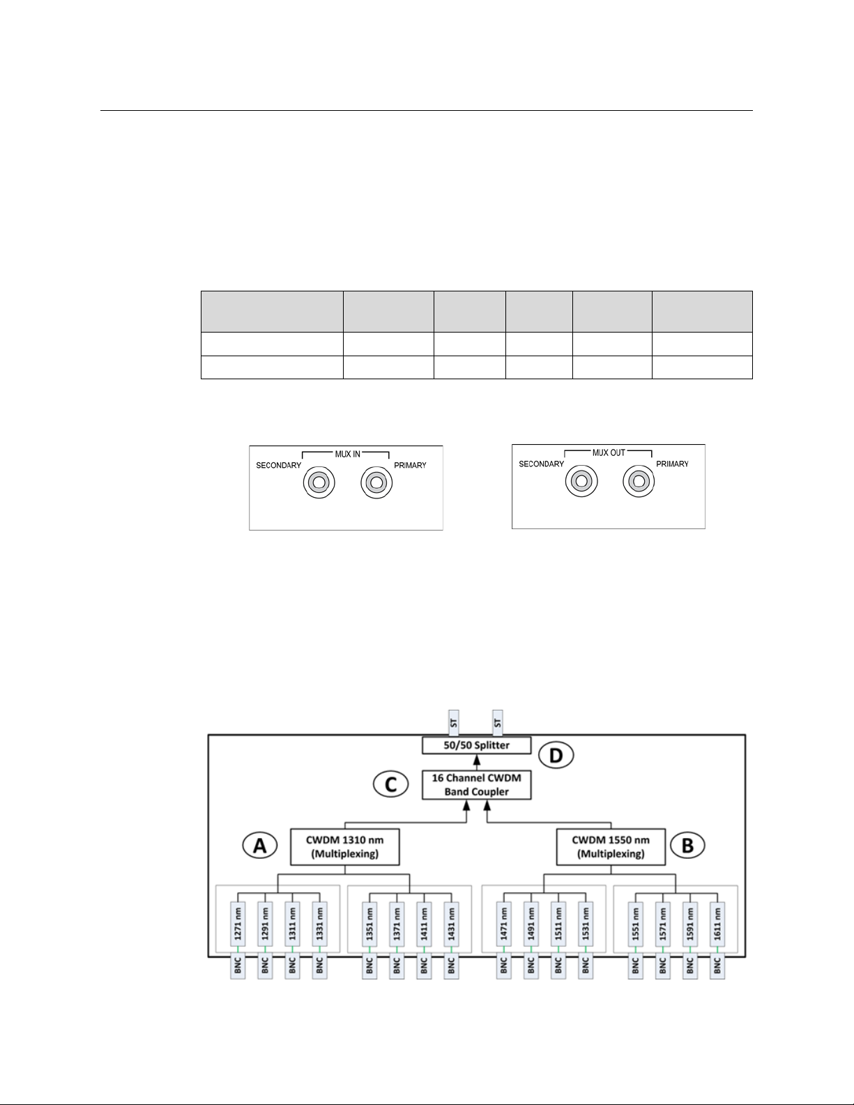
Python 3G Units with CWDM and Fiber Capability (Dual Input/Output)
Python 3G Units with CWDM and Fiber Capability (Dual Input/Output)
Two available models provide internal primary and backup for sixteen channels.
• The transmitter provides duplicate output of up to 16 SDI/Data signals.
• The receiver provides internal failover capability between the duplicate sets of 16
signals.
The models with this feature are listed in the following table. The Primary and Secondary
outputs are identical.
HD/SDI
Part Number Typ e
PY3-GHJK-D16 Transmitter 16 X Yes 2
PY3-RRRR-X16 Receiver X 16 Yes 2
Tra nsm it
HD/SDI
Receive
CWDM
Equipped
Number of
Fibers
The following diagrams illustrate how the primary and backup signals work within the
Python 3G.
Fig. 3-18: The Input and Output ports
• The transmitter has two outputs each carrying eight signals. Both outputs are active all
the time.
• The receiver has two inputs each carrying eight signals.
The Python 3G unit has an internal splitter which receives fiber optic signals from each
input. If a good optic signal is detected on the primary side of the splitter, that set of eight is
used. If for any reason the optic signal is poor or missing, the system will automatically
switch to the secondary side of the splitter.
Fig. 3-19: Python 3G Transmitter with Primary and Backup Outputs
32
Page 37

Python 3G
User Guide
The Python 3G Transmitter equipped with primary and secondary Fiber Optic outputs
utilizes an Optical Splitter (D) to take the 16 Channel CWDM signal and split the signal into
two equal 16 channel outputs.
Fig. 3-20: Python 3G Receiver with Primary and Backup Inputs
The Python 3G Receiver equipped with primary and secondary Fiber Optic inputs utilizes
an Optical Switch to detect which of the incoming Fiber Optic signals is best.
33
Page 38
Python 3G Components
Python 3G Rear Panel Operation
Python 3G Rear Panel Operation
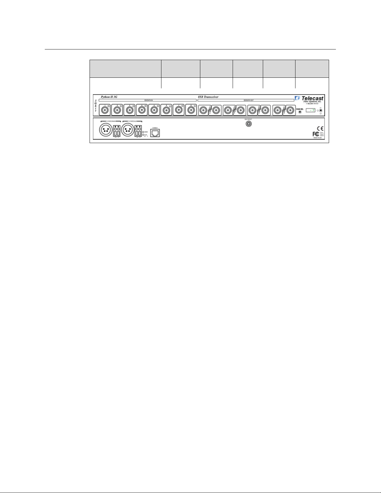
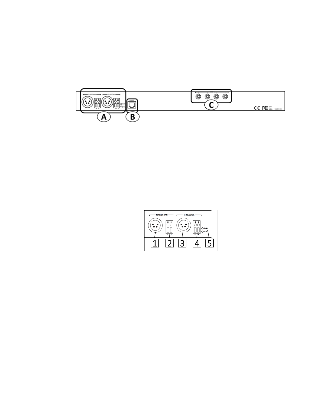
The Python 3G illustration is repeated for ease of use of this Guide. Note that all Python 3G
units operate in the same manner: the only difference is in whether the Fiber Optic ST
connectors are inputs or outputs.
Fig. 3-21: Python 3G Rear Panel
Area A - Rear Panel Power Connectors
The Python 3G provides for the use of redundant 12-18 Volts DC power supplies. A battery
backup option is not provided for the Python 3G unit.
Power can be supplied to the unit by either a 4-pin XLR connector from an external power
supply such as a ADAP-AC-04 or with direct wiring from a 12-18 Volt DC power supply
connected to the provided terminal block.
The main power supply can be of one type (XLR or direct wire) while the Aux power supply
is of the other type.
Fig. 3-22: Rear Panel Power Connectors
• 1 & 2 – Connectors for the Main 12-18 VDC power supply (XLR and Direct wire
terminal block)
• 3 & 4 – Connectors for the Main 12-18 VDC power supply (XLR and Direct wire
terminal block)
• 5 – MAIN/AUX Indicator LEDs:
• The LED for each power supply will be Green if power is being applied to the
Python 3G.
• If both Main and Aux are connected to a power source, both LEDs will be Green.
• A lit LED is not an indication of which power source is being used at the time; only
that the power source is good.
Redundant Power Supply Usage
34
The Python 3G power supply contains circuitry to detect which of the power sources (Main
or Aux) is producing the highest voltage and then uses that source to power the unit. If the
power sources are about the same, the Python 3G uses power from both.
Page 39

Area B – CAN BUS Connector
The CAN BUS connector is inactive in this version of the Python 3G. It may be used for
system monitoring in the future.
CAN is an acronym for Communication Area Network and is a protocol designed to support
the monitoring of microcontrollers.
Area C – The ST Fiber Connectors
Python 3G
User Guide
Fig. 3-23: CAN BUS connector
The MUX IN connector carries up to eight channels from the opposite Python 3G, while the
MUX OUT connector carries the up to eight channels to the opposite Python 3G. These
signals appear on the front panel as four SDI/DATA channels and four Fiber SID/DATA
channels.
Power Connector Wiring
Figure Pin Function
Fig. 3-24: MUX IN and OUT connectors
1Ground
2Unused
3Unused
4
+Power12VDC
This matching connector is from either an ADAP-AC
04 or a customer 12-18 VDC power supply
5 Minus Voltage Terminal
6 Plus Voltage Terminal
35
Page 40

Python 3G Components
Fiber ADAP Power Supplies
Fiber ADAP Power Supplies
The Python 3G requires a power supply providing 12-18 volts at 1.5 Amps. The power
supply recommended for the unit is the ADAP-AC-04-X (X being the specific geography
required). Any power supply meeting the required specification and providing power
through an XLR-4 Female connector can be used. Please contact Grass Valley (Contact Us
on page 49) or your authorized dealer for more information.
Direct wire power connections from a customer provided power source can also be used
with the Terminal Block power connections on the back panel.
Fig. 3-25: Power Supply
Supplied with 4PIN XLR/A4F connector for the power plug on the Python 3G unit (Fiber Part
Number ADAP-AC-04)
36
Page 41

Python 3G Operation
This chapter describes the operation of the Python 3G. Please keep in mind that once the
system is properly set up and configured, there is very little to do during normal operation.
Fiber Optical Channel Monitoring . . . . . . . . . . . . . . . . . . . . . . . . . . . . . . . . . . . . . . . . . . . . . . . . . . . . 38
Using the Python 3G Optical Measurement Display . . . . . . . . . . . . . . . . . . . . . . . . . . . . . . . . . . . 39
Best Practices . . . . . . . . . . . . . . . . . . . . . . . . . . . . . . . . . . . . . . . . . . . . . . . . . . . . . . . . . . . . . . . . . . . . . . . . 42
Troubleshooting . . . . . . . . . . . . . . . . . . . . . . . . . . . . . . . . . . . . . . . . . . . . . . . . . . . . . . . . . . . . . . . . . . . . . 42
37
Page 42

Python 3G Operation
Fiber Optical Channel Monitoring
Fiber Optical Channel Monitoring
The Python 3G provides direct digital readout of the Fiber Optic Link signal strength for
signals received at the unit. This readout is presented in units of dBm. It is useful to
understand both the dB or decibel and the dBm or decibel referenced to one milliwatt.
The decibel (dB) is a logarithmic unit of measurement that expresses the magnitude of a
physical quantity (usually power or intensity) relative to a specified or implied reference
level. Since it expresses a ratio of two quantities with the same unit, it is a dimensionless,
relative unit. A decibel is one tenth of a bel, a seldom-used unit. Typically dB has been
employed in Audio Measurement and Fiber Optics among many uses.
Proper measurement of signal strength requires an absolute measurement and the dBm
provides this measurement. Since it is referenced to the milliwatt, it is an absolute unit,
used when measuring absolute power. By comparison, the decibel (dB) is used for
quantifying the ratio between two values, such as signal-to-noise ratio
The Python 3G operates within a defined range of Fiber Optic Link signal strength. The
minimum recommended signal strength is -20 dBm or better. Typically the system should
operate at levels between -8 dBm and -20 dBm. The standard laser output strength is -6
dBm. Cable length affects signal strength as does the number of connections between the
two Python 3G units. Any use of repeaters of cable bulkhead connector will produce a
minimal signal loss through each connection.
The optical output from each transmitter is generated by an infrared laser diode that is
coupled to a CWDM and onto the fiber. User connections on the Python 3G are made at the
bulkhead ST type connectors on the front and rear panels. Operation is intended for use on
single mode fiber. Since the CWDM output of the Python is the aggregate output of all 8 or
16 optical transmitters inside the frame, the total optical power output on a single fiber
optic cable will be in the +4 to +8 dBm range. Standard practice of NEVER looking directly
into a fiber should be followed at all times.
The maximum fiber distance is defined by the optical loss margin. The RX signal must be 20 dBm or better. Losses on single mode fiber are approximately 0.5 dB/km or less. CWDM’s
account for about 5dBm of loss per pair and must be considered when computing your link
loss budget.
The integrated optical power meter will show the received optical power for each receiver
but note that this figure is post CWDM.
You should read the Using Fiber Optics Guide for information on how to manage and
deploy your fiber optics cabling, safety precautions, tips & tricks, and recommendations for
creating complex fiber optic networks. You can find a copy of this document on the
Support portal (see Contact Us on page 49).
38
Page 43

Using the Python 3G Optical Measurement Display
Flicking the switch
left or right
The optical measurement functionality is similar across all three types of Python 3G. A
transceiver, transmitter, and receiver work identically with one exception. The system
reports fiber optical strength only for fiber optic signals received at a unit. Transmission
strength is not measured.
Python 3G Optical Measurement Display
The Python 3G optical signal strength display has characteristics for the Python 3G
Transmitter, Receiver, and Transceiver.
The Channel Select switch is a dual function switch and functions as follows:
• Flicking the switch to the right allows scrolling through the individual channels to
provide basic status on the signal.
• Flicking the switch to the left provides additional information about the current
channel.
Python 3G
User Guide
Fig. 4-1: Flicking the CHAN SEL switch
Scroll through the signal channels by flicking the switch to the right. The system reports on
the installed SDI channels and the installed fiber channels being transmitted by the unit.
In a 4 x4 Transceiver, the CHAN SEL switch will display the four Transmit channels first
followed by the four Receive Channels.
After the last channel, the display will show the current ambient temperature within the
unit chassis in degress Celsius.
After each flick, the display will indicate the monitored channel such as Tx01 or Tx02 (for the
Transmitter and Transciever) and Rx01 or Rx02 (for the Receiver). For each TX/RX channel,
you can flick the switch to the left to display Technical Information about the channel.
As you scroll through the channels, one of three conditions will be displayed for the
Received channels:
• No fiber link for a channel
• Existing optical link but with no active SDI Data
• Active usable optical link with SDI Data (Available only for Receive channels)
39
Page 44

Python 3G Operation
Display scrolls to reveal temperature.
Python 3G Optical Measurement Display
Condition 1: No Optical Link
If there is no optical link on a particular channel the display will show n/A for not available.
Condition 2 – Optical Link good but no SDI data present.
When an optical link is active, but no SDI data present, the optical power reading will
change between a high and low value, such as -7 and -30.
Fig. 4-2: No Optional Link Display
Fig. 4-3: No SDI Data Present Display
This fluctuation between High and Low occurs because the laser for that channel turns On
and Off until SDI is present. This causes corresponding individual RX channel LED to blink
Red/Green.
Condition 3 - Active usable optical link with SDI Data
When the optical link is good and a valid SDI data stream is present, the optical power level
will be indicated.
Depending on the loss over the distance of the fiber cable run, this value could range from
approximately -5 to -20.
After the last channel is displayed, the ambient temperature inside the frame will be
indicated in degrees Celsius.
40
Page 45

System Firmware Display
The Python 3G display will display the current firmware version when the unit is powered
On. This appears in the display as a scrolling series of alphanumeric character four
characters wide.
Technical Information Display
Flicking the CHAN SEL switch to the left provides additional technical information that
identifies the specific physical channel that is being measured. This information is
presented in scrolling format four characters wide.
Python 3G
User Guide
Fig. 4-4: Firmware display
Fig. 4-5: Technical Information display
41
Page 46

Python 3G Operation
Best Practices
Best Practices
This section is devoted to a number of “Best Practices” for use of the Python 3G System.
• Take every precaution to prevent damaging your eyes while using the equipment.
• Protect the Fiber Optic Cable and the Fiber Optic Connectors. Always keep these
• Read the section on planning the Fiber Run.
• Make sure that the Python 3G unit is secure and cannot be inadvertently moved. The
• Secure the power supplies and power connections so that power is continuous.
• Once the system is set up and running, monitor the system display carefully on the
• Becausethe system is digital, the Signal Strength either meets or exceeds the system
• Be as careful during System tear down as during System setup.
capped unless there are being connected.
The Using Fiber Optics Guide explains how to manage and deploy your fiber optics
cabling, safety precautions, tips & tricks, and recommendations for creating complex
fiber optic networks. You can find a copy of this document on the Support portal (see
Contact Us on page 49).
units may usually be rack mounted and therefore safe and secure, but in instances
where it must be used in “table top” operation, ensure that the connectors on both the
front and rear panels cannot be damaged by being inadvertently struck or pulled.
Python 3G.
requirements. When theSignal Strength is no longer strong enough, the signal stops.
Troubleshooting
Troubleshooting any technical issues with the Python 3G System is similar to any piece of
television production gear, with the exception of the core Fiber Optic technology.
Keep the following in mind:
• Check all your cablesfor any broken connections or bad connectors.
• Ensurethat your Power Supply is working properly.
If you cannot resolve the problem in the field, contact Support (Contact Us on page 49).
42
Page 47

Understanding Python 3G Model Numbers
This chapter explains how to decode the Python 3G Part Number. Sample part numbers are
decoded at the end of this section.
Part Numbers . . . . . . . . . . . . . . . . . . . . . . . . . . . . . . . . . . . . . . . . . . . . . . . . . . . . . . . . . . . . . . . . . . . . . . . . 44
Example Python 3G Models . . . . . . . . . . . . . . . . . . . . . . . . . . . . . . . . . . . . . . . . . . . . . . . . . . . . . . . . . . . 46
43
Page 48

Understanding Python 3G Model Numbers
Part Numbers
Part Numbers
The Python 3G part number consists of three sections as described below:
• A - The product designation – in this case PY3 stands for Python 3G
• B - Channel Card Options – the four letters correspond to the four available slots. If a
position has “0,” then the slot is empty. The available card options are listed below.
• C - Fiber I/O Options – typically varies between “ST” for ST connectors with straightthrough conversion for SDI/Data to or from Fiber Optic signal. “W” for units with
CWDM. The number indicates the number of fiber optic channels.
The I/O options are listed below.
Fig. 5-1: Python 3G part number
Part Number Card Options
Code
Letter
A Transmit Straight-through Convert All 1310 nm
R Receive Straight-through Convert Detector for any wavelength
G Transmit CWDM 1310 Low Range:
H Transmit CWDM 1310 High Range:
J Transmit CWDM 1550 Low Range:
K Transmit CWDM 1550 High Range:
Usage
Typ e
(All cards have 4 channels)
Wavele ngth
1271, 1291, 1311, 1331 nm
1351, 1371, 1411, 1431 nm
1471, 1491, 1511, 1531 nm
1551, 1571, 1591, 1611 nm
44
Page 49

Fiber I/O Cards
Desig. Usage Typ e Wavelength
ST4 Receive or Transmit 4 – Fiber I/O NA
ST8 Receive or Transmit 8 – Fiber I/O NA
ST12 Receive or Transmit 12 – Fiber I/O NA
ST16 Receive or Transmit 16 – Fiber I/O NA
W16 Receive or Transmit 1 – Fiber I/0 – 16 channels CWDM
W41 Receive or Transmit 4 Channel 1310 Low Range CWDM
W42 Receive or Transmit 4 Channel 1310 High Range CWDM
W43 Receive or Transmit 4 Channel 1550 Low Range CWDM
W44 Receive or Transmit 4 Channel 1550 High Range CWDM
W83 Receive or Transmit 8 Channel 1310 Range CWDM
W85 Receive or Transmit 8 Channel 1550 Range CWDM
D16 Transmitter 16 Channel Dual Redundant Output CWDM
Python 3G
User Guide
D41 Transmitter 4 Channel 1310 Low Range
Dual Redundant Output
D42 Transmitter 4 Channel 1310 High Range Dual Redundant
Output
D43 Transmitter 4 Channel 1550 Low Range Dual Redundant
Output
D44 Transmitter 4 Channel 1550 High Range Dual Redundant
Output
D83 Transmitter 8 Channel 1310 Range Dual Redundant Output CWDM
D85 Transmitter 8 Channel 1550 Range Dual Redundant Output CWDM
X16 Receiver 16 Channel on Dual Switched Input CWDM
X41 Receiver 4 Channel on Dual Switched Input 1310 Low
Range
X42 Receiver 4 Channel on Dual Switched Input 1310 High
Range
X43 Receiver 4 Channel on Dual Switched Input 1550 Low
Range
X44 Receiver 4 Channel on Dual Switched Input 1550 High
Range
X83 Receiver 8 Channel on Dual Switched Input 1310 Range CWDM
CWDM
CWDM
CWDM
CWDM
CWDM
CWDM
CWDM
CWDM
X85 Receiver 8 Channel on Dual Switched Input 1550 Range CWDM
45
Page 50

Understanding Python 3G Model Numbers
Example Python 3G Models
Example Python 3G Models
Model PY3-RRR0-W83W43 – Receiver with 12 Channels equipped with CWDM and 2 Fibers I/O
Position Item Description
Card Slot #1 R 4 straight-through conversion channels
Card Slot #2 R 4 straight-through conversion channels
Card Slot #3 R 4 straight-through conversion channels
Card Slot #4 0 No card installed
I/O #1 W83 8 Channel Demux card for 1310 nm wavelength
on its own fiber
I/O #2 W43 4 Channel Demux card for 1310 nm wavelength on its own fiber
Model PY3- PY3-GHJK-D16 – Transmitter with 16 Channels equipped with CWDM and 2 Dual Fiber I/O
Position Item Description
Card Slot #1 G CWDM Multiplexer 1310 nm Low Range
Card Slot #2 H CWDM Multiplexer 1310 nm High Range
Card Slot #3 J CWDM Multiplexer 1550 nm Low Range
Card Slot #4 K CWDM Multiplexer 1550 nm High Range
I/O #1 D16 Dual Output 16 channels on Dual Redundant Fiber Output
I/O #2 NA
Model PY3-AR00-ST8– Transceiver with 4 Transmit Channels and 4 Receive Channels with straightthrough conversion to Fiber Optic signal equipped with 8 Fiber I/O
Position Item Description
Card Slot #1 A 4 straight-through transmit conversion 1310 nm channels
Card Slot #2 R 4 straight-through receive conversion channels
Card Slot #3 No card installed
Card Slot #4 No card installed
I/O #1 ST8 8 ST Connectors Fiber I/O
I/O #2 NA
46
Page 51

Specifications
Video
Transmission Method....................................................................................................... Digital
Input Level. ...........................................................................................800 mV (Peak To Peak)
Input/Output Impedance.......................................................................................... 75 Ohms
Return Loss ......................................................................................>15 dB, 5 Mhz To 1.5 Ghz
.............................................................................................................. >10 dB, 1.5 Ghz To 3 Ghz
Coaxial Input Equalization
Maximum Rate ............................................................................................................... 3 Gb/S
Equalization At 3 Gb/S................................................................ 300m Of Belden 1694A
Bit-Error Rate (@ -22 dBm Rx Optical Power).............................................................. 10
Jitter (Using Pathological Data Pattern) ................................................................... <0.2 UI
Transmission
Operating Wavelength..................................... 1310 nm Or 1550 nm Optical Window
Optional CWDM available
Link Margin................................................................................................................ Up To 22dB
Transmitter Output Power Options ........................................................................... -7 dBm
Receiver Sensitivity ........................................................................................................-20 dBm
Optical Source ..........................................................................................................Laser Diode
Optical Detector........................................................................................................................PIN
Fiber Type ................................................................................................................. Single Mode
-12
Mechanical/Environmental
Dimensions (LxWxH) ...................................................................................10.5”x16.7”x1.75”
Weight, each end….............................................................................................................. 5 lbs
Connectors
Electrical ................................................................................................................................BNC
Optical ........................................................................................................................................ST
Input voltage............................................................................................................... 12-18 VDC
Power consumption......................................................................................................... <15 W
Indicators.................................................. Power ON, SDI Data Presence, Optical Power
Temperature Range ...............................................................................................-20° to 55 °C
Humidity Range ..........................................................................0 to 95 % non-condensing
Compliance
Laser Safety...............................................................................Class 1 Laser 21 CFR 1040.10
EMI/RFI....................................................................................Complies with IEC/EN 60825-1
Certifications ..........................................................................................................................RoHS
47
Page 52

Specifications
48
Page 53

Grass Valley Technical Support
For technical assistance, please contact the Grass Valley Technical Support center nearest
you:
Contact Us
Americas
Office hours: 9:00 a.m. – 9:00 p.m. (EST)
Telephone: 1-800-224-7882
Fax: +1 514 335 1614
E-mail: support@miranda.com
Europe, Middle East, Africa, UK
Office hours: 9:00 a.m. – 6:00 p.m. (GMT)
Telephone: +44 118 952 3444
Fax: +44 118 952 3401
E-mail: eurotech@miranda.com
France
Office hours: 9:00 a.m. – 5:00 p.m. (GMT+1)
Telephone: +33 1 55 86 87 88
Fax: +33 1 55 86 00 29
E-mail: eurotech@miranda.com
Corporate Head Office
Asia
Office hours: 9:00 a.m. – 6:00 p.m. (GMT+8)
Telephone: +852 2539 6987
Fax: +852 2539 0804
E-mail: asiatech@miranda.com
China
Office hours: 9:00 a.m. – 6:00 p.m. (GMT+8)
Telephone: +86 10 5873 1814
E-mail: asiatech@miranda.com
Malaysia
Telephone: +60 3 2247 1808
EMERGENCY After Hours (Global)
Toll Free: 1-800-224-7882 (US and Canada)
Telephone: +1 514 333 1772
Grass Valley
3499 Douglas-B.-Floreani
St-Laurent, Quebec H4S 2C6
Canada
Telephone: +1 514 333 1772
Fax: +1 514 333 9828
Web: www.miranda.com
 Loading...