

Page 1

Instruction Manual
Profile
®
RAID Storage
PRS 250
Printed in USA or United Kingdom
Tektronix, Inc.
PO Box 1000
Wilsonville, OR 97070-1000 USA
1-800-547-8949 (USA and Canada)
1-503-682-7300
http://www.tek.com
N 60
Page 2
Copyright 1998 Tektronix, Inc. Wilsonville, Oregon.
Printed in the United States of America or the United Kingdom. All rights reserved. This document may not be copied in whole or in part, or
otherwise reproduced except as specificallypermittedunder U.S. copyright law, without the prior written consent of Tektronix, Inc., P.O. Box
1000, Wilsonville, Oregon 97070-1000 USA.
TEKTRONIX, TEK, and Profile are registered trademarks of Tektronix, Inc. Other trade names used in this document are trademarks or
registered trademarks of the manufacturers or vendors of the associated products.
Manual Revision Status
PRODUCT: PRS250 RAID Storage
REV DATE DESCRIPTION
May 1998 Original Issue. Manual part number 071-0226-00.
Page 3

Tektronix Product Support
You can get technical assistance, check on the status of problems, or report new problems by
contacting our Product Support Group.
United States and Canada
Monday–Friday 5:30AM–5:00PM Pacific Time (800) 547-8949
Europe
Monday–Friday 9:00AM–5:30PM
Austria 222-799-3535 Netherlands 010-495-4255
Belgium 02-714-3401 Norway 22-83-85-69
Denmark 3543-5259 Spain 91-564-4692
Finland 161-691-98559 Sweden 08-679-8419
Germany 069-935-25001 Switzerland 041-210-6009
Italy 44-1908-681-706 United Kingdom 01908-681-703
Luxembourg 400-848 Other 44-1908-681-703
Email: EuroProfile@tek.com
Asia and South America
Australia 61-2-888-7066 Korea 82-2-528-5299
Brazil 55-11-543-1911 Mexico 52-5-666-6333
Hong Kong 852-2585-6688 Singapore 65-356-3900
Japan 81-3-3448-3111 Taiwan 886-2-765-6362
World Wide
24-hour Emergency Hotline (503) 685-2345 (Contract and warranty customers)
World Wide Web http://www.tek.com/VND/support
FTP Site ftp.tek.com
Email ProfileSupport@tek.com
i
Page 4

ii
Page 5

Table of Contents
General Safety Summary
Injury Precautions .................................................................................................................. v
Product Damage Precautions................................................................................................ vi
Safety Terms and Symbols.................................................................................................... vi
Regulatory Information
Certifications and Compliances.............................................................................................. vii
Chapter 1 Introduction
Organization of the Manual.................................................................................................... 1-1
About the RAID Storage Chassis........................................................................................... 1-2
RAID Storage Components.................................................................................................... 1-3
Storage-control Processor (SP) ........................................................................................ 1-4
Disk Drive Modules ........................................................................................................... 1-5
Voltage Semi-regulated Converters (VSCs)...................................................................... 1-6
Fan Module ....................................................................................................................... 1-7
Chapter 2 Installation
Installing RAID in a Cabinet................................................................................................... 2-1
Attaching the Slot Matrix Label.......................................................................................... 2-1
Mounting RAID in a Cabinet.............................................................................................. 2-1
Configuring the Profile Disk Drives ........................................................................................ 2-8
Removal of Profile Internal Disk Drives............................................................................. 2-8
Connection to the Profile System........................................................................................... 2-10
Connecting Serial (console) Cables.................................................................................. 2-10
Setting SP SCSI IDs.......................................................................................................... 2-11
Configurations and Cabling............................................................................................... 2-13
Two-Channel Profile/Single-SP RAID .......................................................................... 2-14
Two-Channel Profile/X Single-SP RAIDs..................................................................... 2-15
Two-Channel PDR200/One Dual-SP RAID ................................................................. 2-16
Four Channel Profile/2 RAIDs...................................................................................... 2-17
Four-Channel Profile/Multiple RAIDs............................................................................ 2-18
Four-Channel PDR200/One Dual-SP RAID................................................................. 2-20
Connecting the Power Cord.............................................................................................. 2-21
Powering Up the Storage Chassis .................................................................................... 2-22
Configuring and Managing the RAID ..................................................................................... 2-23
Running DASSMGR.......................................................................................................... 2-23
Before You Begin ......................................................................................................... 2-23
Starting DASSMGR...................................................................................................... 2-23
Setting Password Protection............................................................................................. 2-24
Changing the Password.................................................................................................... 2-25
Setting Storage System Date and Time............................................................................ 2-26
Chapter 3 Servicing the System
Checking Status with the Presentation Utility......................................................................... 3-1
Moving the Grid Cursor ................................................................................................ 3-4
Reconfiguring a Storage System ........................................................................................... 3-5
Changing Physical Disk Configurations ............................................................................ 3-5
Adding Disk Modules and Creating New Logical Units ................................................ 3-5
Binding Disk Modules as a Logical Unit ....................................................................... 3-6
Binding with Two SPs................................................................................................... 3-8
Unbinding a Physical Disk Unit..................................................................................... 3-9
RAID Instructions iii
Page 6

Table of Contents
Changing Physical Disk Unit Parameters ......................................................................... 3-10
Changing the Rebuild Time.......................................................................................... 3-10
Updating Licensed Internal Code...................................................................................... 3-11
Installing a New Revision of Licensed Internal Code................................................... 3-12
Upgrade and Repair of a Storage System............................................................................. 3-14
Handling CRUs ................................................................................................................. 3-15
Avoiding Electrostatic Discharge (ESD) Damage ........................................................ 3-15
Emergency Procedures (without an ESD kit)............................................................... 3-16
Precautions When Removing, Installing, or Storing CRUs .......................................... 3-16
Opening and Closing the Fan Module............................................................................... 3-17
Replacing or Adding a Disk Module.................................................................................. 3-18
Removing a Disk Module ............................................................................................. 3-18
Installing a Disk Module ............................................................................................... 3-20
Removing or Installing a Disk Filler Module...................................................................... 3-22
Installing or Removing SP Memory Modules.................................................................... 3-23
Installing SP Memory Modules..................................................................................... 3-23
Removing SP Memory Modules................................................................................... 3-24
Replacing an SP ............................................................................................................... 3-25
Removing an SP .......................................................................................................... 3-25
Installing an SP ............................................................................................................ 3-27
Removing or Installing an SP Filler Board ........................................................................ 3-28
Replacing or Adding a VSC .............................................................................................. 3-30
Replacing a Fan Module................................................................................................... 3-32
Appendix A Technical Specifications
AC power requirements................................................................................................ A-1
Power cables................................................................................................................ A-1
Operating limits ............................................................................................................ A-1
Non-operating limits (shipping and storing).................................................................. A-1
Physical........................................................................................................................ A-2
Service clearance......................................................................................................... A-2
Cabling......................................................................................................................... A-2
Miscellaneous............................................................................................................... A-2
Appendix B Ordering Information
Customer Replaceable Units................................................................................................. B-1
Field Replaceable Units......................................................................................................... B-2
iv RAID Instructions
Page 7

General Safety Summary
General Safety Summary
Review the following safety precautions to avoid injury and prevent
damage to this product or any products connected to it.
Only qualified personnel should perform service procedures.
While using this product, you may need to access other parts of the
system. Read the General Safety summary in other system manuals for
warnings and cautions related to operating the system.
Injury Precautions
Use Proper Power
Cord
Ground the Product This product is grounded through the grounding conductor of the power
Do Not Operate
Without Covers
Use Proper Fuse To avoid fire hazard, use only the fuse type and rating specified for this
Do Not operate in
Wet/Damp
Conditions
Do Not Operate in an
Explosive
Atmosphere
Avoid Exposed
Circuitry
To avoid fire hazard, use only the power cord specified for this product.
cord. To avoid electric shock, the grounding conductor must be
connected to earth ground. Before making connections to the input or
output terminals of the product, ensure that the product is properly
grounded.
To avoid electric shock or fire hazard, do not operate this product with
covers or panels removed.
product.
To avoid electric shock, do not operate this product in wet or damp
conditions.
To avoid injury or fire hazard, do not operate this product in an explosive
atmosphere.
To avoid injury, remove jewelry such as rings, watches, and other
metallic objects. Do not touch exposed connections and components
when power is present.
RAID Instructions v
Page 8
General Safety Summary
Product Damage Precautions
Use Proper Power
Source
Use Proper Voltage
Setting
Provide Proper
Ventilation
Do Not Operate With
Suspected Failures
Do not operate this product from a power source that applies more than
the voltage specified.
Before applying power, ensure that the line selector is in the proper
position for the power source being used.
To prevent product overheating, provide proper ventilation.
If you suspect there is damage to this product, have it inspected by
qualified service personnel.
Safety Terms and Symbols
Terms in This
Manual
!
!
!
!
These terms may appear in this manual:
WARNING:Warning statementsidentify conditionsor practices that can
result in personal injury or loss of life.
CAUTION: Caution statements identify conditions or practices that can
result in damage to the equipment or other property.
Terms on the
Product
Symbols on the
Product
!
!
These terms may appear on the product:
DANGER indicates a personal injury hazard immediately accessible as
one reads the marking.
WARNING indicates a personal injury hazard not immediately
accessible as you read the marking.
CAUTION indicates a hazard to property including the product.
The following symbols may appear on the product:
DANGER high voltage
Protective ground (earth) terminal
ATTENTION – refer to manual
vi RAID Instructions
Page 9

Regulatory Information
Regulatory Information
Certifications and Compliances
Canadian Certified
Power Cords
Canadian Certified
AC Adapter
FCC Emission
Control
Canadian EMC
Notice of
Compliance
Canadianapproval includes the products and power cordsappropriate for
use in the North America power network. All other power cords supplied
are approved for the country of use.
Canadian approval includes the AC adapters appropriate for use in the
North America power network. All other AC adapters supplied are
approved for the country of use.
This equipment has been tested and found to comply with the limits for a
Class A digital device, pursuant to Part 15 of the FCC Rules. These limits
are designed to provide reasonable protection against harmful
interference when the equipment is operated in a commercial
environment. This equipment generates, uses, and can radiate radio
frequency energy and, if not installed and used in accordance with this
installation manual, may cause harmful interference to radio
communications. Operation of this equipment in a residential area is
likely to cause harmful interference in which case the user will be
required to correct the interference at his or her own expense. Changes or
modifications not expressly approved by Tektronix can affect emission
complianceand could void the user’s authority tooperate this equipment.
This digital apparatus does not exceed the Class A limits for radio noise
emissions from digital apparatus set out in the Radio Interference
Regulations of the Canadian Department of Communications.
EN55022 Class A
Warning
Le présent appareil numérique n’émet pas de bruits radioélectriques
dépassant les limites applicables aux appareils numériques de la classe A
préscrites dans le Règlement sur le brouillage radioélectrique édicté par le
ministère des Communications du Canada.
For products that comply with Class A. In a domestic environment, this
product may cause radio interference, in which case the user may be
required to take adequate measures.
RAID Instructions vii
Page 10

Regulatory Information
viii RAID Instructions
Page 11

Chapter
1
Introduction
This manual explains how to install the rack-mounted RAID Storage chassis, how to
configure and manage the system, and how to replace and/or add customer
replaceable units (CRUs). The manual is for technical personnel who want to install
and maintain the RAID Storage chassis. It assumes familiarity with Profile
Professional Disk Recorders. For information on RAID usage, see the Profile User
Guide.
NOTE: Using the PRS250 RAID Storage chassis requires Profile System Software
V2.2 or higher. For optimum performance from your PRS250, you should use
Profile System Software V2.4.
Organization of the Manual
The manual is organized into chapters which are identified and briefly described
below.
Chapter 1 - Introduction: Introduces the RAID Storage chassis and its components.
Chapter 2 - Installation: Describes how to install and configure the RAID Storage
chassis.
Chapter 3 - Servicing the System: Describes how to monitor and service the RAID
Storage chassis.
Appendix A: Lists the technical specifications of the RAID Storage chassis.
Appendix B: Provides ordering information for CRUs and Field Replaceable Units
for the RAID Storage chassis.
RAID Instructions 1-1
Page 12
Chapter 1 Introduction
About the RAID Storage Chassis
This RAID Storage provides a compact, high-capacity, high-availability source of
disk storage for the Profile Professional Disk Recorder. A single RAID Storage
chassis offers a large capacity of high-availability disk storage in as many as 20 disk
modules that can individually be replaced while the system is powered up.
Two models are available, the PRS250 and the PRS250M. The PRS250M offers two
storage processors, which increase the bandwidth of the RAID chassis.
Approximate storage times
Video Compression Type 10 Disk Drives 15 Disk Drive 20 Disk Drives
M-JPEG 6 hours 9 hours 12 hours
MPEG 12 hours 18 hours 24 hours
a.
At 24 Mb/sec for MJPEG, 8 Mb/sec for MPEG, 4 audio tracks per video
a
The following table lists the maximum number of RAIDs that can be connected to a
Profile Professional Disk Recorder.
Maximum number of RAIDs per Profile system
Number Of Profile Channels Maximum Number of RAID Chassis
26
412
a.
Requires Profile System Software V2.4. To reach maximum
capacity, connect no more than 3 RAID chassis per SCSI bus,
with no other external SCSI devices connected.
a
1-2 RAID Instructions
Page 13
RAID Storage Components
The RAID Storage chassis contains the components listed below.
• One (PRS250) or two (PRS250M) storage-control processors (SP).
• 10, 15, or 20 disk drive modules.
• One fan module.
• Three voltage semi-regulated converters (VSCs) power supplies
The SPs, disk modules, fan module, and VSCs in the RAID Storage chassis are
customer-replaceable units (CRUs), which you can install or replace yourself.
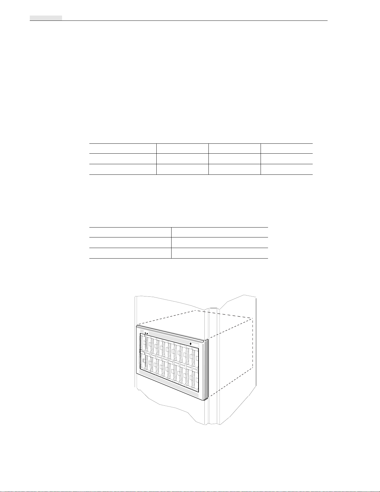
The following illustration shows the location of the RAID’s CRUs, which also
include the SCSI bus cable, SCSI terminator plug, power cord, and the optional
asynchronous cables. In addition to the CRUs, the RAID Storage chassis contains
field-replaceable units (FRUs). Only qualified service personnel should replace an
FRU.
Location of the customer-replaceable units in the storage chassis
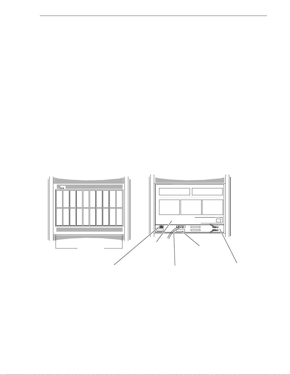
RAID Storage Components
Front of RAID Storage chassis
A0
A1
B0
B1
C0
C1
D0
D1
E0
E1
A2
A3
B2
B3
C2
C3
D2
D3
10,15, or 20
Disk drive
modules
Power cord
E2
E3
Back of RAID Storage chassis
Fan module
(not shown)
SCSI bus cable
SP A SP B
VSC
VSC
SCSI terminator
plug
VSC
Serial cables
(optional)
RAID Instructions 1-3
Page 14
Chapter 1 Introduction
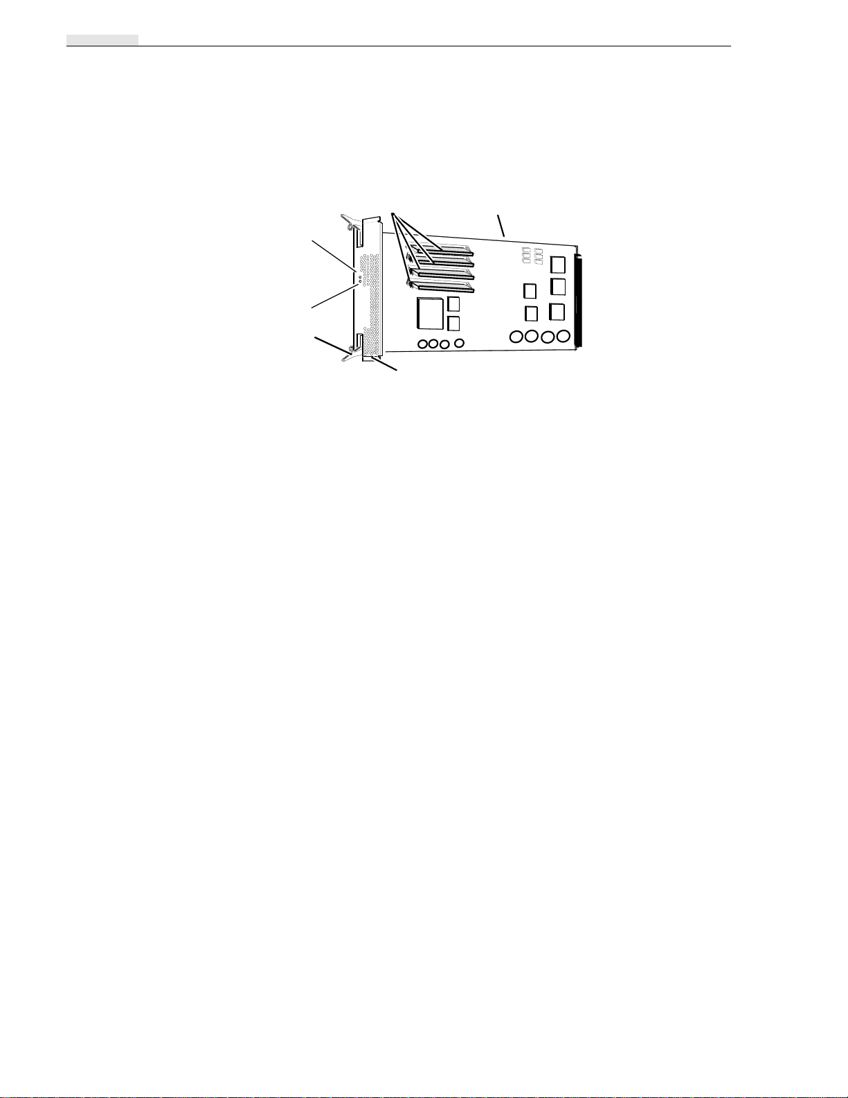
Storage-control Processor (SP)
Memory modules
Service light
(amber)
Ready light
(green)
Latch
Bezel
Printed-circuit
board
TheSP consists ofa printed circuitboard with two or four memory modules (DIMMs)
and a bezel with status lights, and latches to secure the SP in place. The memory
modules provide 32 Mbytes of SP memory. The SP uses 4Mbytes of this memory for
system buffers. The remaining memory is available for system use.
Two status lights on the SP indicate the following:
Ready light (green) — Lights while the SP is powered on and operating normally.
Service light (amber) — Lights when the SP is not working properly.
The SPs are visible when you swing the fan module down from the back of the RAID
Storage chassis.
The SPprocesses data written to or read from the disk drive modules, and controls the
disk modules in the storage chassis through a synchronous SCSI bus. It has five
internal SCSI buses, each supporting four disk drive modules for a total of 20 disk
drive modules. The Disk Array Storage System Manager (dassmgr) uses an RS-232
connection to the RAID Storage chassis to communicate with an SP. Using the
dassmgr, you can set up RAID Storage memory, bind disk modules into logical units
(LUNs), update the RAID Storage Licensed Internal Code, and check RAID Storage
status.
A second SP increases the RAID chassis bandwidth for improved performance,
provided the two SPs are connected to separate SCSI busses. Do not connect both SPs
to the same SCSI bus.
IMPORTANT You should never attempt to replace any of the SP’s
components, except the memory modules.
1-4 RAID Instructions
Page 15
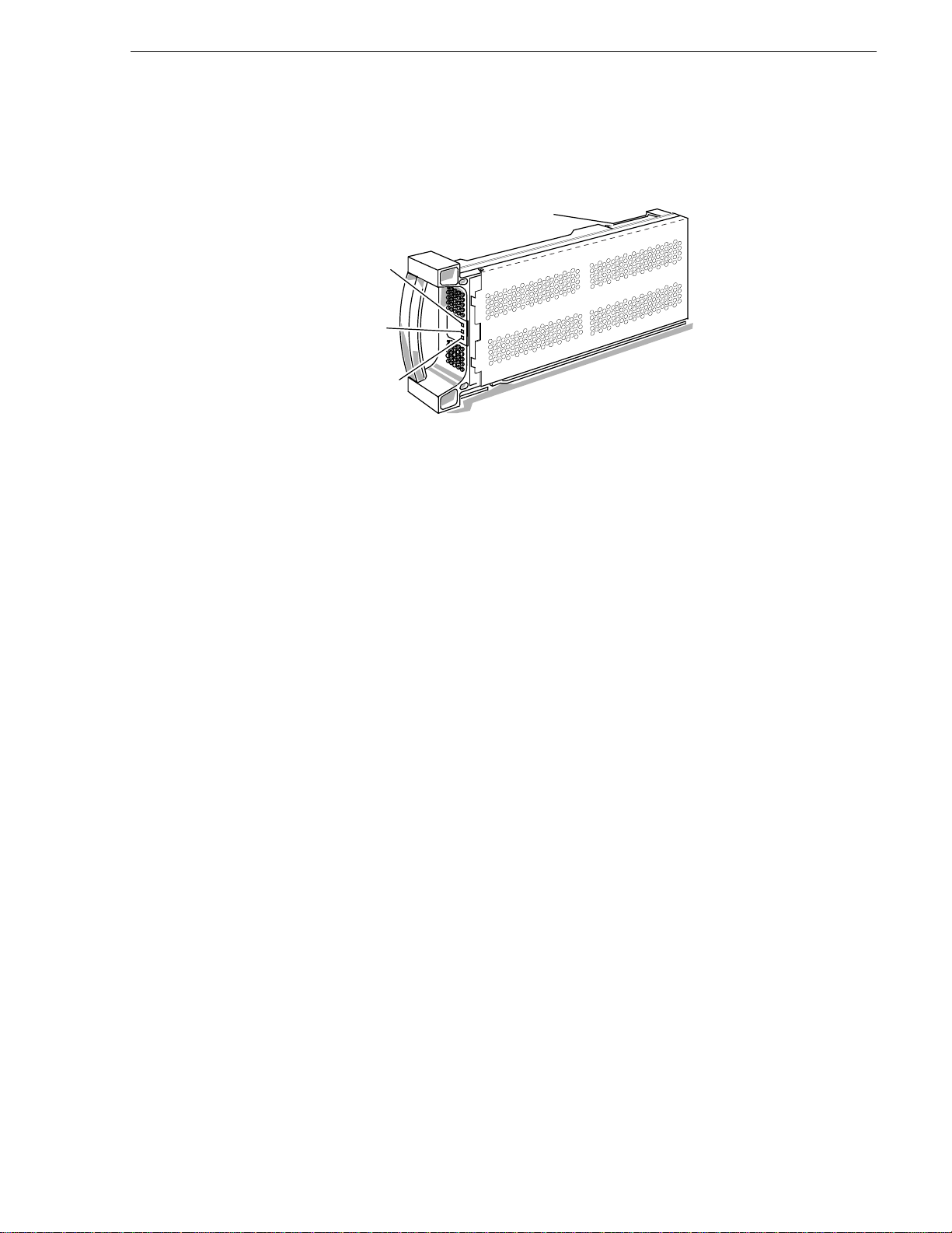
Disk Drive Modules
Ready light
(green)
Busy light
(green)
Fault light
(amber)
A disk drive module, also called a disk module, consists of a disk drive, a power
regulator board, internal cabling, and a plastic carrier. The carrier has a handle and
guides for inserting and holding the module in the RAID Storage chassis. A label
attached to the carrier’s side shows the drive module’s model number and capacity.
Disk Drive Modules
Disk drive module’s model
number label
Three status lights on the module indicate the following:
Ready light (green) — Lights while the disk drive module is powered up and ready
for use.
Busy light (green) — Lights while the drive is in use; for example, during formatting
or user I/O operations.
Fault light (amber) — Lights when the module is shut down by the SP because the
module failed. Also lights after you replace the drive, while the replacement drive
spins up to speed.
You can remove or install any one module at a time within a group of five drives
either while the storage chassis is running or in the idle mode (not running). You
should never open a disk drive module or attempt to replace any of its internal
components.
RAID Instructions 1-5
Page 16
Chapter 1 Introduction
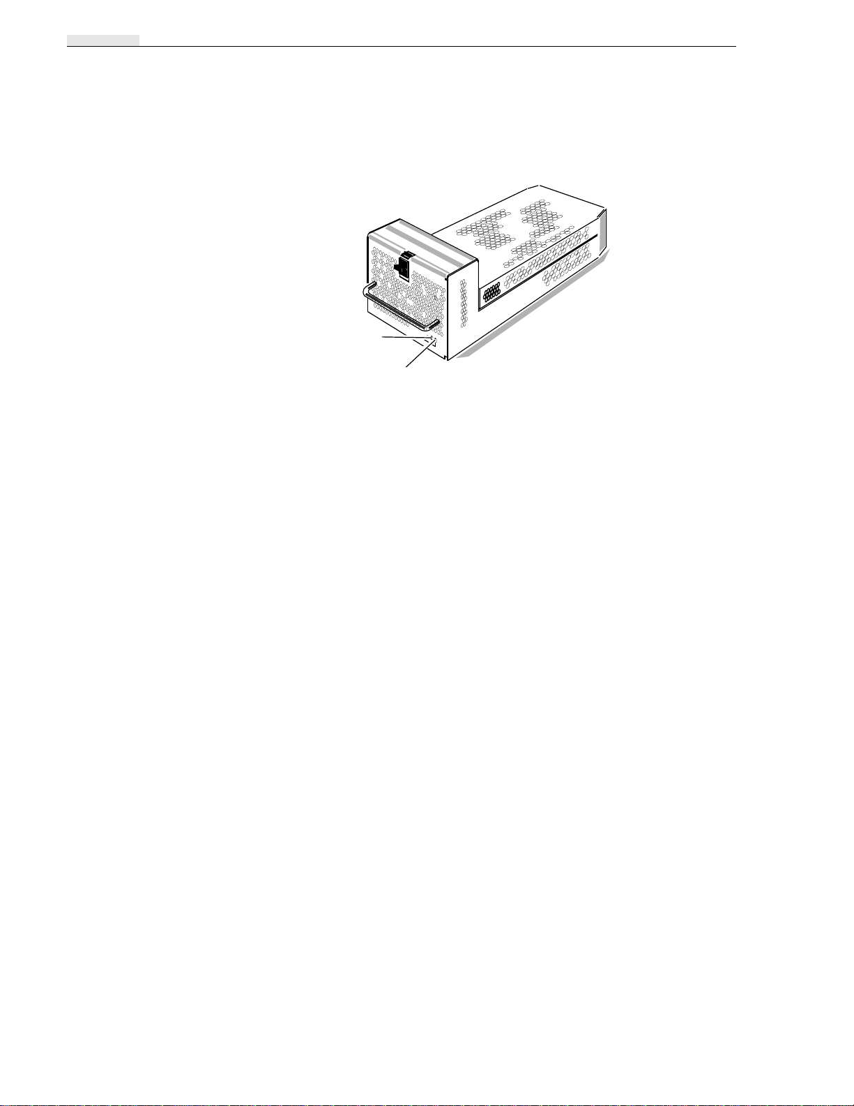
Voltage Semi-regulated Converters (VSCs)
The VSCs are power supplies that convert the installation site’s ac line voltage to the
48, 24, and 18Vdc required to power the modules in the RAID Storage chassis. The
chassis contains three VSCs for high-availability operation.
Replace light
(amber)
Ready light
(green)
Two status lights on each VSC indicate the following:
Ready light (green) — Lights while VSC is operating normally.
Replace light (amber) — Lights when the SP determines that the VSC has failed.
The VSCs are visible when you swing the fan module down on the back of the RAID
Storage chassis.
You can remove or install a VSC while the storage chassis is running.
If a VSC fails, replace it as quickly as possible. With three VSCs, if one of them fails,
the RAID Storage continues to operate but you still should replace the failed VSC as
soon as possible to restore high-availability operation. Failure to replace the VSC
could cause the RAID Storagechassis to shut downif either the fan module or another
VSC fails. You should never open a VSC or attempt to replace any of its internal
components.
1-6 RAID Instructions
Page 17
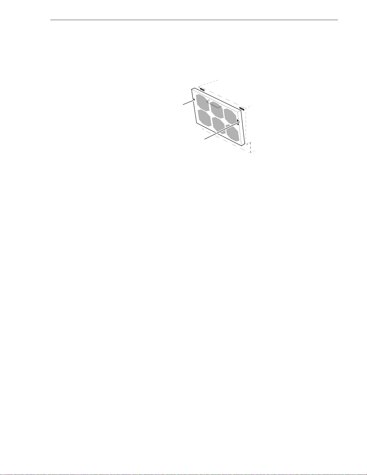
Fan Module
The RAID Storage chassis uses a single fan module, also called a fan pack, that
attaches to the back of the chassis. The fan module contains six high-capacity,
multiple speed fans, and a control/monitor board.
Fan Module
Replacelight
(amber)
Lock
One status light on the fan module indicates the following:
Replace light (amber) — Lights when a fan in the module is not working.
For high-availability operation, if a fan stops working, the remaining five fans speed
up to maintain air flow. The Replace light turns on to indicate that you must replace
the fan module as soon as possible.
The fan module is mounted on hinges so you can swing it down away from the
chassis. A mechanical lock and magnetic catches hold the fan module closed.
NOTE:If the fan moduleremains open formore than approximately 2minutes, the
storage chassis automatically shuts down to prevent overheating.
You can remove a fan module while the storage chassis is running. You should never
open the module or attempt to replace any of its internal components. If one of the
fans in the module fails, replace the fan module as quickly as possible to maintain
high-availability operation. Failure to replace the module could cause the RAID
Storage to shut down if either a VSC module or another fan fails.
RAID Instructions 1-7
Page 18

Chapter 1 Introduction
1-8 RAID Instructions
Page 19

Chapter
2
Installation
The procedures in this chapter assume the installation site meets the ac power
requirements and operating limits listed in Appendix A.
Installing RAID in a Cabinet
Attaching the Slot Matrix Label
Three sticky-backed labels are shipped with the storage chassis: a rack slot matrix
diagram showing the disk drive module locations, and two sheets of stickers for
identifying disk modules. Attach the rack slot matrix to your storage chassis so it is
visible. Save the two sheets of stickers for the person configuring the disk modules
into physical disks.
Mounting RAID in a Cabinet
You can mount RAID in a standard 19-inch cabinet using the hardware mounting kit,
which is supplied with the storage chassis.
WARNING: Since the RAID chassis weighs a minimum of about 46 kg (101 lbs),
installing it in the cabinet requires at least two people.
WARNING: Before opening the cabinet to install RAID, follow the cabinet
manufacturer’s recommendations for powering down the cabinet.
RAID Instructions 2-1
Page 20
Chapter 2 Installation
To install RAID in a cabinet
1. If you want to lessen the weight of the chassis, remove disk modules from the chassis
CAUTION: If you remove disk modules from the RAID chassis, be sure to label
each module and return all the modules to their original locations. Failure to
correctly locate the disk modules will result in one or more inaccessible LUNs, and
may even make the entire storage chassis inaccessible.
(see Removing a Disk Module in Chapter 3), making sure that as you remove each
module, you write on the module’s label the ID number of the slot (A0, for example)
from which you removed the module. Black out the lower ten slot postions on the slot
matrix label, since these positions are not available on the PRS250.
For the slot ID numbers, refer to the slot matrix label, which you should have just
attached to the RAID chassis, or to the following illustration.
Disk module slot ID numbers
A0
A1
B0
B1
C0
C1
D0
D1
E0
E1
A2
A3
B2
B3
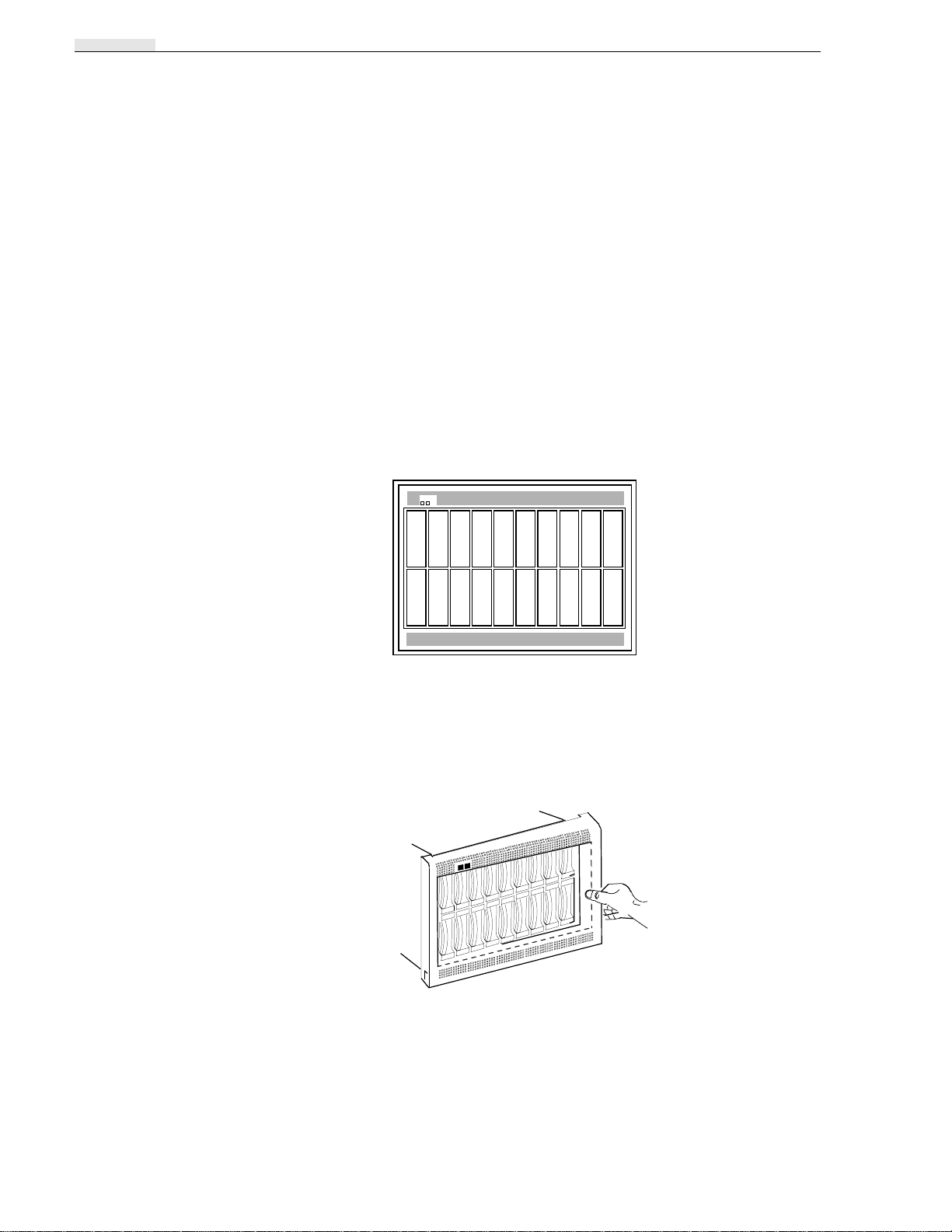
2. Remove the chassis front panel as shown below.
Removing the front panel
E2
C2
D2
E3
C3
D3
Pull panel from one
side then the other.
3. Remove any trim and/or open the doors of the cabinet in which you are installing
2-2 RAID Instructions
the chassis. For information on opening the cabinet, refer to the documentation for
the cabinet.
Page 21
Mounting RAID in a Cabinet
4. Attach the mounting rails to the cabinet according to the following instructions,
using the rails and parts in the hardware mounting kit.
a. Make sure that you have 14-inch clearance in the cabinet in which you will
install the storage chassis.
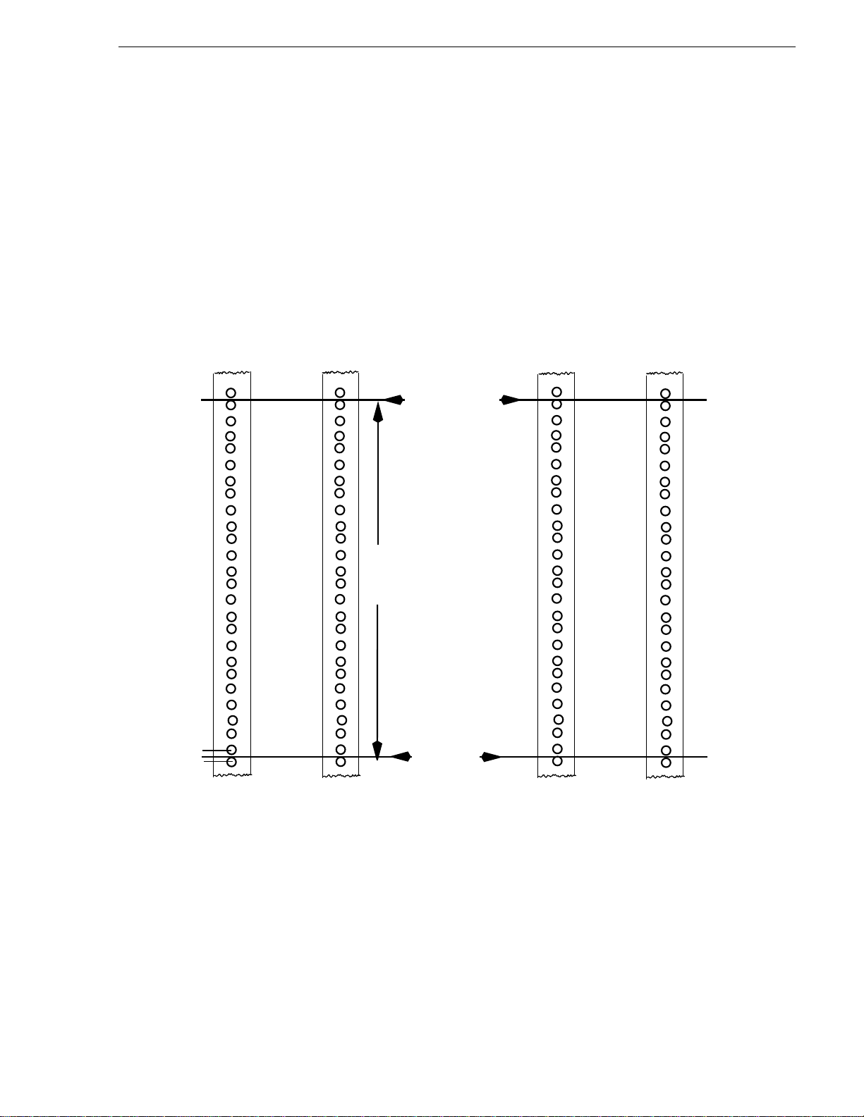
b. Mark and label a baseline in a 1/2-inch space (measured between the center of
adjacent holes) on the front and middle cabinet channels, as shown in the
following illustration. (Do not position the baseline between two 5/8-inch
spaced holes.)
Chassis location in the cabinet
1/2
inch
space
Front cabinet channels
Middle cabinet channels
toptop
Top of chassis
24 holes
or
14 inches
Base line
(bottom of chassis)
IMPORTANT You must mark a baseline in a 1/2-inch space or the chassis
won’t fit in the space where you plan to install it. The spaces on a channel,
measured between the center of adjacent holes, are either 1/2 inch or 5/8 inch
wide.
c. From the baseline, count up 24 holes. Mark the top-of-chassis line above the top
hole on the front and middle cabinet channels, as shown in the illustration.
RAID Instructions 2-3
Page 22
Chapter 2 Installation
2
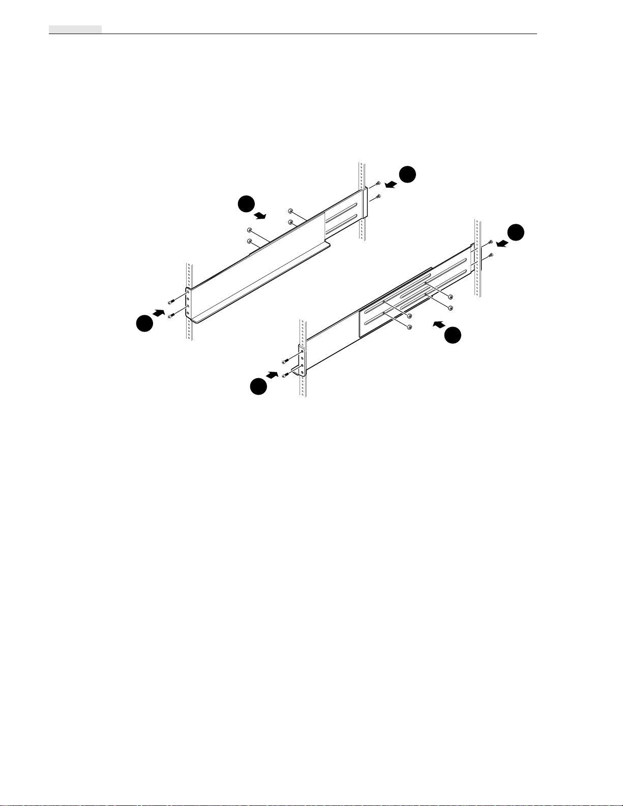
d. .Loosen thesecuring nuts➊on the two mounting railsas shown in the following
illustration.
Attaching the rails
2
1
2
0226-7
1
Slide rails to correct
length and tighten nuts
2
e. .If the front channel does not have threaded screw holes, attach clip nuts to the
front channel.
f. Align the bottom of the rail is aligned with the baseline mark on the cabinet’s
channel. Attach the mounting rails to the rack mount cabinet as shown (➋).
2-4 RAID Instructions
Page 23
Mounting RAID in a Cabinet
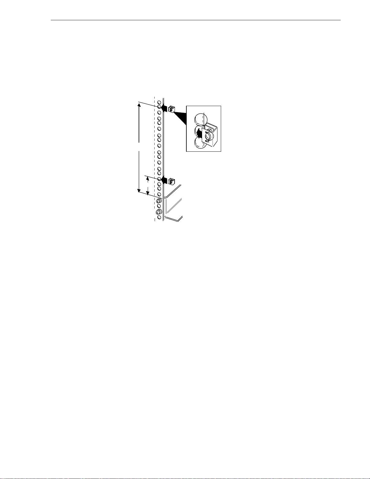
g. Slide the two clip nuts onto each front channel as shown below.
Attaching the clip nuts
Counting from the top of the rail, slide
clip nuts onto the 4th and 17th holes
of each front channel.
Rail
You are now ready to install the chassis in the cabinet
RAID Instructions 2-5
Page 24
Chapter 2 Installation
CAUTION: Do not lift the RAID chassis by the handle on the fan module at the
back of the storage chassis or by the disk drive module handles.
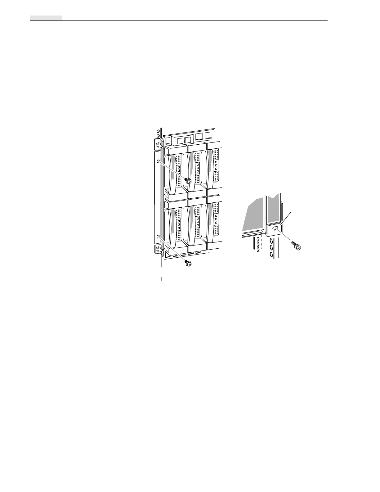
5. Mount the storage chassis in the cabinet with the remaining parts in the hardware
A. Slide chassis onto rails and
into the cabinet.
B. Fasten front of chassis to
cabinet with four screws
(2perside).
mounting kit as shown in the following illustration.
Attaching the storage chassis to the cabinet
Rail
C. Fasten back of chassis to left
and right rails with two screws
(1 per rail).
6. Reinstall any disk modules that you removed, being sure to put each module back
into its original slot.
2-6 RAID Instructions
Page 25
Mounting RAID in a Cabinet
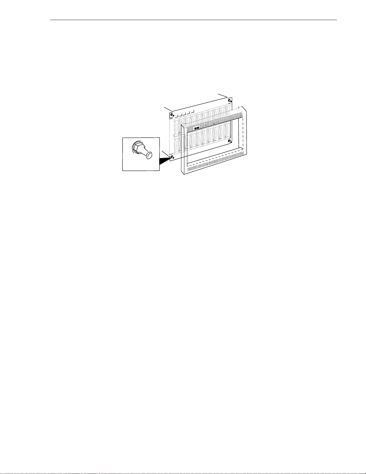
7. Reinstall the storage chassis’s front panel as shown in the following illustration.
Installing the front panel
Ballstud
Press panel onto four ballstuds.
(one at each corner)
8. Reinstall any trim you removed from the cabinet, and close any cabinet doors you
opened.
RAID Instructions 2-7
Page 26

Chapter 2 Installation
Configuring the Profile Disk Drives
The Profile disk recorder internal drives can not be used when a RAID unit is
connected. To disable the Profile system’s internal disk drives and enable the RAID
Storage, refer to your Profile User Manual.
Removal of Profile Internal Disk Drives
NOTE: Only qualified service personnel should perform the following procedure.
If you want to use a Profile disk recorder with attached RAID Storage, and are sure
you will not be using thatProfile without RAID Storage, you can remove the Profile
system’s internal disk drives for use elsewhere. Two procedures follow, one for the
PDR100 and one for the PDR200.
Removing PDR100 Internal Drives
To remove the internal disk drives from the PDR100, perform the following
procedure:
1. Turn all power to the Profile Off.
NOTE: You should NOT discard any hardware or cables.
2. Refer to your Profile Service Manual to remove the top cover from the Profile
chassis.
3. Refer to your Profile Service Manual to remove the SCSI cable(s). (If you have a
2-channelsystem there willbe a SCSI A cable only. If you have a 4-channel system
there will be both a SCSI A and a SCSI B cable.)
4. Refer to your Profile Service Manual to remove the Hard Disk Carrier Tray from
the Profile chassis.
5. Refer to your Profile Service Manual to remove the hard disk drives from the tray.
(There will be 4 hard disk drives if you have a 2-channel system and 8 hard disk
drives if you have a 4-channel system.)
6. Refer to your Profile Service Manual to reinstall the empty Hard Disk Carrier Tray
into the Profile chassis.
7. Use cable ties to anchor the loose hard disk drive cable(s) to the inner top edge of
the Hard Disk Carrier Tray.
8. Attach jack screws (2 each, P/N 214-4689-00) to the bus terminator (P/N
011-0170-00), both of which came with your RAID Storage chassis. Refer to ➊ in
the following illustration.
9. Attach the bus terminator(s) to the Disk Recorder board(s). (There will be one
board if you have a 2-channel system and two if you have a 4-channel system.)
Refer to ➋ in the following illustration
2-8 RAID Instructions
Page 27
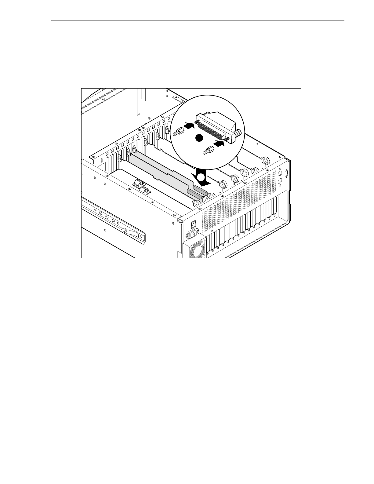
Removal of Profile Internal Disk Drives
Installing the internal disk recorder terminator
1
2
.
10.Reinstall the Profile covers.
Removing PDR200 Internal Disk Drives
To remove the internal disk drives from the PDR200 perform the following
procedure:
1. Turn all power to the Profile system off.
NOTE: You should NOT discard any hardware or cables.
2. Refer to your Profile Service Manual to remove the top covers from the Profile
chassis.
3. Refer to your Profile Service Manual to remove the hard disks from the system. At
the same time, remove the SCSI cable(s) connected between the disk recorder
board(s) and the SCSI Distribution board.
4. Reinstall the Profile chassis covers.
9674-20
RAID Instructions 2-9
Page 28

Chapter 2 Installation
Connection to the Profile System
The RAID Storage chassis connects to the Profile disk recorder through a wide
SCSI-2 differential bus. This SCSI bus connection allows the Profile system to
communicate with the disks in the RAID Storage chassis. Also, you can administer,
configure, and monitor the RAID Storage chassis using dassmgr through an
asynchronous communications connection between its asynchronous (console) port
and the Profile system’s RS-232 port.
The procedures in this chapter assume the following:
• You have all the cables and cable adapters that you need.
• If necessary, someone has installed and/or updated the Profile System Software.
• The Profile operating system is shutdown, and the Profile disk recorder is turned
• If the Profile system has a PDX Disk Expansion unit, it must be removed from the
Connecting Serial (console) Cables
off.
system. You can not connect both a RAID and a PDX Disk Expansion unit to the
same Profile disk recorder.
To use dassmgr to bind disk modules into logical units, set up storage chassis
caching, and monitor storage chassis operation, you must connect the console SP port
for each SP in a storage chassis to an serial port of the Profile system.
1. Attach a 25-pin female-to-9-pin female null modem cable to the Profile system’s
RS-232 connector in the upper right corner on the Profile system’s rear panel.
Attaching the 25-pin female-to-9-pin female null modem cable
Profile system’s
RS-232 connector
2. Attach the male end of the serial (console) cable to the 25-pin connector on the
2-10 RAID Instructions
adapter cable.
Page 29

Setting SP SCSI IDs
3. Attach the other end of the serial cable to the RAID CONSOLE SP-A connector. See
the following illustration.
Attaching the cable to the SP’s console A connector
Rear of storage chassis
Setting SP SCSI IDs
Each SP connected to the same SCSI bus requires a unique SCSI ID number (that is,
a number that is not used by any other device on the bus). The back of the storage
chassis, see the following illustration, has two SCSI ID switch packs. Each switch
pack has four switches (ID0-ID3). One switch pack sets the SCSI ID for SP A, and
the other sets the SCSI ID for SPB. Set the SCSI ID switches for both SP A and SPB
to 8, if this ID is unused. If it is used, set their SCSI IDs to the next highest unused ID
number.
NOTE: If you wish to configure your RAID Storage units as two external file
systems, the RAID Storage units in the second file system must be set to SCSI ID s
12 and higher. Refer to the Disk Utility section of the Profile User manual for
information on how to create file systems.
B
A
Flat blade
screwdriver
RAID Instructions 2-11
Page 30

Chapter 2 Installation
Back of storage chassis
SP B
SCSI ID
ID 0
ID 1
ID 2
ID 3
ID 0
ID 1
ID 2
ID 3
Setting an SP’s SCSI ID
ON
SCSI ID Switch number
number ID 0 ID 1 ID 2 ID 3
0 OnOnOnOn
1 Off On On On
2 On Off On On
3 Off Off On On
4 On On Off On
5 Off On Off On
6 On Off Off On
7 Off Off Off On
8 OnOnOnOff
9 Off On On Off
10 On Off On Off
11 Off Off On Off
12 On On Off Off
13 Off On Off Off
14 On Off Off Off
15 Off Off Off Off
SP A
SCSI ID
TheProfile will support two separate external filesystems. The RAIDStorage chassis
is an external attachment which can be assigned SCSI IDs 8 through 15.
If the RAID units are configured as two external file systems, the first unit or pair of
units of the second file system must be set to SCSI ID 12. If only a single RAID is to
be used, it should be assigned the lowest SCSI ID available. See the following two
examples.
EXAMPLE 1: Two RAIDs daisy-chained to a Profile with a single external SCSI
bus would have SCSI IDs 8 & 9.
EXAMPLE 2: Six RAIDs attached to a Profile with two external SCSI buses
(three daisy-chained RAIDs to each bus) would have SCSI IDs 8, 9, & 10 on each
bus.
NOTE: RAID units should be attached symmetrically to the two buses (that is, the
same number of RAIDs on each bus with the same number of disk modules in each
chain).
2-12 RAID Instructions
Page 31

Configurations and Cabling
You can connect your PRS250/M in a variety of ways, depending on your Profile
Disk Recorder model and the whether your RAID chassis has one (PRS250) or two
(PRS250M) SPs. Choose the procedure on the following pages that most closely
matches your needs. As stated earlier in this chapter, if the Profile has a PDX disk
expansion unit it must be removed. For installations involving multiple RAID units
keep in mind the maximum number of RAIDs that can be used with your Profile disk
recorder. Refer to About the RAID Storage Chassis on page 1-2 for more information.
The following illustration shows SCSI connectors on the rear panel of a RAID unit.
RAID SCSI connectors
Back view
Configurations and Cabling
SCSI-B INSCSI-A IN
SCSI-A
OUT
SCSI-B
OUT
NOTE: SCSI-B connectors are used on a PRS250 only (two SPs).
RAID Instructions 2-13
Page 32

Chapter 2 Installation
Two-Channel Profile/Single-SP RAID
This configuration, see the following illustration, consists of a two-channel Profile
disk recorder (one Master Disk Recorder - MDR) connected to a single RAID chassis
with one SP.
1. Connect a SCSI-2 cable from the Profile MDR rear panel connector to the RAID
2. Connect a SCSI terminator plug to the RAID chassis SCSI A OUT connector.
chassis SCSI A IN connector.
2-Channel Profile Disk Recorder
SCSI-2 Cable
RAID Chassis
J10
SCSI-2 Terminator
0226-1
2-14 RAID Instructions
Page 33

Two-Channel Profile/X Single-SP RAIDs
This configuration, see the following illustration, consists of a two-channel Profile
disk recorder (one MDR) connected to multiple RAID chassis, daisy-chained
together.
1. Connect a SCSI-2 cable from the Profile MDR rear panel connector to the first
RAID chassis SCSI A IN connector.
2. Connect a second SCSI-2 cable from the first RAID chassis SCSI A OUT
connector to the second RAID chassis SCSI A IN connector.
3. Connect a third SCSI-2 cable from the second RAID chassis SCSI A OUT
connector to the third SCSI A IN connector.
4. Repeat Steps 2 and 3 for the remaining number of RAIDs. See page 2-13 to
determine the maximum number of RAIDs that can be connected to your Profile
disk recorder.
5. Connect a SCSI terminator to the SCSI A OUT connector of the last RAID chassis
in the chain.
Configurations and Cabling
2-Channel Profile Disk Recorder
J10
RAID Chassis
SCSI-2 Cable
SCSI-2 Terminator
0226-2
RAID Instructions 2-15
Page 34

Chapter 2 Installation
Two-Channel PDR200/One Dual-SP RAID
This configuration, see the following illustration, consists of a two-channel PDR200
(one Master Disk Recorder - MDR) connected to a single RAID chassis with two SPs.
1. Connect a SCSI-2 cable from the Profile MDR rear panel connector (SCSI-A) to
2. Connect a SCSI-2 cable from the PDR200 SCSI-B rear panel connector to the
3. Connect a SCSI terminator plug to the RAID chassis SCSI A OUT connector.
4. Connect a SCSI terminator plug to the RAID chassis SCSI B OUT connector.
the RAID chassis SCSI A IN connector.
RAID chassis SCSI B IN connector.
2-Channel Profile Disk Recorder
SCSI B
SCSI-2 Cable
RAID Chassis
J10
SCSI-2 Terminator
0226-3
2-16 RAID Instructions
Page 35

Four Channel Profile/2 RAIDs
This configuration, see the following illustration, consists of a 4-channel Profile (one
MDR and one Slave Disk Recorder - SDR) and two symmetrical RAID Storage
chassis (each RAID chain with the same number of disk modules).
1. Connect a SCSI-2 cable from the Profile MDR rear panel connector to the RAID
chassis SCSI A IN connector
2. Connect a second SCSI-2 cable from the SDR rear panel connector to a second
RAID SCSI A IN connector.
3. Connect a SCSI terminator plug to each RAID chassis SCSI A OUT connector.
4-Channel Profile Disk Recorder
Configurations and Cabling
SCSI-2 Cable
RAID Chassis
J11
J10
SCSI-2 Terminator
Note:
Each RAID chassis must have
the same number of drives.
0226-6
RAID Instructions 2-17
Page 36

Chapter 2 Installation
Four-Channel Profile/Multiple RAIDs
This configuration, see the following illustration, has a four-channel Profile (one
MDR and one SDR) and two symmetrical RAID Storage chassis chains (the RAID
chainattached to the MDR matches, innumber of disk modules, thechain attached
to the SDR).
1. Connect a SCSI-2 cable from the Profile MDR rear panel connector to the first
2. Connect a SCSI-2 cable from the first RAID chassis SCSI A OUT connector to the
3. Connect a SCSI-2 cable from the second RAID chassis SCSI A OUT connector to
4. Repeat Steps 2 and 3 for the remaining RAIDs in the MDR chain. See page 2-13
5. Connect a SCSI-2 cable from the Profile SDR rear panel connector to the first
6. Connect a SCSI-2 cable from the first RAID chassis SCSI A OUT connector to the
RAID chassis SCSI A IN connector in the MDR chain.
next RAID chassis SCSI A IN connector in the MDR chain.
the next RAID chassis SCSI IN connector in the MDR chain.
to determine the maximum number of RAIDs that can be connected to your Profile.
RAID chassis SCSI A IN connector in the SDR chain.
second RAID chassis SCSIA IN connector in the SDR chain.
7. Connect a SCSI-2 cable from the second RAID chassis SCSI A OUT connector to
the next RAID chassis SCSI IN connector in the SDR chain.
8. Repeat Steps 6 and 7 for the remaining RAIDs in the SDR chain. Remember to not
exceed the maximum number of RAIDs that can be attached to your Profile.
9. Connect a SCSI terminator plug to the SCSI A OUT connector of the last RAID
chassis in each chain.
2-18 RAID Instructions
Page 37

4-Channel Profile Disk Recorder
Configurations and Cabling
SCSI-2 Cable
J10
J11
RAID Chassis Chain
RAID Chassis Chain
SCSI-2 Terminator
Note:
Each RAID chassis chain must
have the same number of drives.
0226-5
RAID Instructions 2-19
Page 38

Chapter 2 Installation
Four-Channel PDR200/One Dual-SP RAID
This configuration, see the following illustration, consists of a four-channel PDR200
(one Master Enhanced Disk Recorder - MEDR, one Slave Enhanced Disk Recorder SEDR) connected to a single RAID chassis with two SPs.
1. Connect a SCSI-2 cable from the PDR200 MEDR rear panel connector (SCSI-A)
2. Connect aSCSI-2 cable from the PDR200 SEDR rear panelconnector to theRAID
3. Connect a SCSI terminator plug to the RAID chassis SCSI A OUT connector.
4. Connect a SCSI terminator plug to the RAID chassis SCSI B OUT connector.
to the RAID chassis SCSI A IN connector.
chassis SCSI B IN connector.
4-Channel Profile Disk Recorder
SCSI-2 Cable
RAID Chassis
J11
J10
SCSI-2 Terminator
0226-4
2-20 RAID Instructions
Page 39

Connecting the Power Cord
1. Make sure that the storage chassis power switch is off, then connect the power cord
to the storage chassis.
NOTE: Several types of power cord are supplied with the product. Use the power
cord that is appropriate to your installation.
2. Plug the other end of the power cord into an ac power outlet.
Plugging in the ac power cord
Back of storage
Connecting the Power Cord
A. Push power switch
to off (0) position.
B. Plug power cord into
power connector.
You are ready to power up the storage chassis as described in the following section,
Powering Up the Storage Chassis.
RAID Instructions 2-21
Page 40

Chapter 2 Installation
Powering Up the Storage Chassis
NOTE: When powering up a Profile with RAID system, the RAID unit must be
turned on at least two minutes before power is applied to the Profile.
1. Turn on the storage chassis’s power and wait two minutes.
The green power light on the front of the storage chassis turns on and the fans
rotate.
Turning on storage chassis power
Back of storage
2. Power up the Profile. (See Profile’s Installation manual for information on how to
power up the Profile.)
Front of storage chassis
2-22 RAID Instructions
Page 41

Configuring and Managing the RAID
Configuring and Managing the RAID
To set up the RAID Storagechassis, you need to setthe storage chassis date, time, and
optional password protection.
You perform these tasks using the Disk Array Storage System Manager
(DASSMGR).
Running DASSMGR
You can run DASSMGR from a bootable diskette, or install it on the Profile system
hard disk and run it from that disk.
Before You Begin
Before you can run DASSMGR, someone must have performed these tasks:
• Connected the storage chassis to the Profile.
• Connected the RS-232 port on the storage chassis to a spare COM port on the
Profile. See “Connecting Serial (console) Cables” on page 2-10.
Starting DASSMGR
To start DASSMGR:
1. Power up the storage chassis.
IMPORTANT Make sure you specify the correct communications port when you
issue the DASSMGR command in the next step. Specifying the wrong port may
cause problems with the device connected to that port.
2. Run DASSMGR using the command DASSMGR x, where x represents the
communication port. For example, to run DASSMGR with communication port 2,
at the MS-DOS command prompt enter
DASSMGR 2 ↵
The Disk Array Storage System Manager Main Menu appears. Use the up, down,
and Enter keys on your keyboard to move around in the menus.
Disk Array Storage System Manager Main Menu
Grid Management (monitor, bind & unbind arrays)
Update Licensed Internal Code
Update Drive Code
Change COM port (present port set to COM1)
Exit
RAID Instructions 2-23
Page 42

Chapter 2 Installation
Setting Password Protection
Password protection lets you restrict access to functions that can destroy all data on
logical units. To enable password protection, you enable password mode and specify
a password. This password is then required to access the GridMgr Main Menu.
To specify a password:
1. From the DASSMGR Main Menu, select the Grid Management option.
2. From the GridMgr Main Menu, follow this menu path:
SP A
SP SCSI ID 1 Change Storage System Parameters Menu
1. View System Memory Configuration
2. Change Main Menu Password
3. Change System Date and Time
Change Parameters → Change Storage System Parameters
The Change Storage System Parameters Menu appears, similar to the following.
At any prompt enter ˆ to GO BACK TO PREVIOUS MENU, ? for HELP
Enter Choice:
3. From the Change Storage System Parameters Menu, choose the Change Main
Menu Password option.
The Password Utility screen appears, similar to the following.
Password Utility
Enter ? for HELP, ^ to GO BACK TO PREVIOUS MENU
Set password:(Y/N/?/^)?[N]
Enable password mode:(Y/N) ?[N]
Enter new password:(CR/NL for none)
Verify new password:
9613-1
2-24 RAID Instructions
Page 43

4. At the Set password prompt, enter Y.
5. At the Enable password mode prompt, enter Y.
6. At the Enter new password prompt, enter the password.
The password can be up to 15 characters, and can consist of any characters except
the null character and defined control characters. The password is case sensitive,
so you must specify your password exactly as you have defined it.
7. At the Verify new password prompt, enter the same password again.
Once you have set and enabled a password, you are prompted for the password at the
Presentation Utility screen. See “Checking Status with the Presentation Utility” in
Chapter 3. After you enter the correct password, you can access the GridMgr Main
Menu. If password mode is disabled, you are not prompted for the password.
Changing the Password
If you have specified apassword, DASSMGR asks forthat password when youselect
the Change Main Menu Password option from the Change Storage System
Parameters Menu. The Password Utility screen appears.
Changing the Password
Password Utility
Enter ? for HELP, ^ to GO BACK TO PREVIOUS MENU
Enter old password:(password/?/^)?
To change the password
1. At the Enter old password prompt, enter the password that you had
originally specified.
2. At the Change password prompt, enter Y.
3. At the Enable password mode prompt, enter Y.
4. At the Enter new password prompt, enter the new password.
5. At the Verify new password prompt, enter the new password again.
RAID Instructions 2-25
Page 44

Chapter 2 Installation
Setting Storage System Date and Time
The storage chassis clock controls the date and time displayed on the Presentation
Utility screen and with events recorded in an SP’s unsolicited event log. This clock is
local to the storage chassis, and has no relation to the Profile’s system or boot clock.
To set the storage chassis date and time:
1. From the GridMgr Main Menu, follow this menu path:
SP A
SP SCSI ID 1 Change Storage System Parameters Menu
1. View System Memory Configuration
2. Change Main Menu Password
3. Change System Date and Time
Change Parameters → Change Storage System Parameters
The Change Storage System Parameters Menu appears, similar to the following.
At any prompt enter ˆ to GO BACK TO PREVIOUS MENU, ? for HELP
Enter Choice:
9613-1
2-26 RAID Instructions
Page 45

Setting Storage System Date and Time
2. From the Change Storage System Parameters Menu, choose the Change System
Date and Time option.
The Change System Date and Time screen appears, similar to the following.
SP A Change System Date and Time
SP SCSI ID 1
Current system time is: 10/12/1995 (Monday) 22:44:06
Enter the new system time in the format: MM/DD/YYYY HH:MM:SS. HH
is the number of hours that have elapsed since midnight (0-23).
Enter a ^ if you do not want to change the system time.
New time:
At the New time prompt, enter the new date and time, or type ^ if you want to
leave the time unchanged.
The format for the date and time is
MM/DD/YYYY HH:MM:SS
For example, 06/01/1996 01:23:55.
RAID Instructions 2-27
Page 46

Chapter 2 Installation
2-28 RAID Instructions
Page 47

Chapter
3
Servicing the System
This chapter describes how to service the RAID Storage chassis.
Checking Status with the Presentation Utility
You can check storage-system status using the Presentation Utility. Perform the
following steps to display the DASSMGR Presentation Utility screen:
1. Start DASSMGR.
2. From the Disk Array Storage System Manager Main Menu, select the appropriate
COM port.
3. From the Disk Array Storage System Manager Main Menu, select Grid
Management.
4. From the Gri d Main Menu, select the Presentation Utility option.
NOTE: If the Presentation Utility screen does not appear, enter carets (^) until the
GridMgr Main Menu appears, and then choose the Presentation Utility option.
A Presentation Utility screen appears similar to the following:
RAID Instructions 3-1
Page 48

Chapter 3 Servicing the System
Sample Presentation Utility screen
Module
Status
SPidentifier
SPSCSIID
Disk status
LUN number
Heartbeat
(blinking asterisk)
Fault field (on a fault,
displays blinking
FAULT message)
SPA
SPSCSIID0
PROM Revision
1.01
FAN A OK Microcode Revision
FAN B OK 2.00.00
VSC A OK StatisticsLogging
VSC B OK DISABLED
VSC C OK
BBU -- REMOVED
The grid above shows a 20 slot storage system configured as follows:
* Two five-disk RAID-3 groups (LUN 0 and LUN 1). LUN 0 includes modules A0, B0, C0, D0, and E0. LUN 1 includes
modules A1, B1, C1, D1, and E1. The status of each disk module in LUN 0 is ENA, and in LUN 1 is BIN (binding).
* Ten empty slots are also shown. The empty module slots include modules A2, B2, C2, D2, E2, A3, B3, C3, D3, and E3.
0 ENA ENA ENA ENA ENA
00000
A B C D E
1 BIN BIN BIN BIN BIN
11111
Grid cursor
SCSI bus
PresentationUtility(*)
06/01/1996 14:33
2
A B C D E
Peer SP
3
Requests Completed
6K
Cache States
Write:DISABLED
Read:DISABLED
Heartbeat — Following the screen title (Presentation Utility) is an asterisk in
parentheses (*). This asterisk indicates the heartbeat status of the SP. It should blink
every several seconds to indicate that the SP is functioning. If it does not appear to
blink, the SP may not be working. Try pressing Ctrl-Q. If the asterisk still does not
blink, the SP requires service.
Storage System date and time — The date and time of the storage chassis, which is
controlled by the storage chassis’s clock, appears under the screen title (Presentation
Utility). This date and time is also displayed with the storage chassis log events. You
can set the date and time as described in Setting the Storage-system Date and Time
later in this chapter.
SP identifier — Specifies the SP (SP A or SP B) connected to the asynchronous
RS-232 port you are using.
3-2 RAID Instructions
Page 49

Checking Status with the Presentation Utility
Module status — The first column shows the status of the fan modules and VSC
(voltage semi-regulated controller) modules.
FAN x - Fan module status codes are as follows:
Code Fan module status
OK Operating normally.
- - Failed.
VSC x - VSC module status codes are as follows:
Code Fan module status
OK Operating normally.
- - Failedor not present. If youdo not know whether aVSC has failed, examine the fault
light on the VSC.
BBU - Holds up the RAID-3 buffer while the SP attempt to write the contents of the
buffer to disk in the event of a power failure.
BBU status codes are as follows:
Code Fan module status
OK Operating normally.
NRR Not ready, charging. After a power outage, a BBU takes 15 minutes or less to
recharge. From total depletion, recharging takes an hour less.
TE Weekly BBU test is in progress.
- - Failed or not present.
Disk status — In the grid itself, the blocks of boxes identify slots for disk modules in
the chassis. Associated with each slot is an identifier (ID) based on the slot’s position
in the chassis. You identify a disk module by its disk ID, which is the ID of the slot
containing it. A disk ID is made up of a letter indicating the SCSI bus for the slot and
a number indicating the slot’s position on the SCSI bus. The disk IDs for the storage
chassis are
SCSI bus Positions Disk IDs
A0, B0, C0, D0, E0
A1, B1, C1, D1, E1
A2, B2, C2, D2, E2
A3, B3, C3, D3, E3
For each slot that contains a disk module, the box shows a three letter status code. The
table on the next page lists the status codes. If a disk module is not bound, the
displayed code is UNB with two asterisks (**). For a bound module, the box shows
the code and logical unit number (of the RAID group, individual unit, or hot spare) to
which the module is bound. A box without text indicates an empty slot, that is, one
not containing a disk module.
RAID Instructions 3-3
Page 50

Chapter 3 Servicing the System
Moving the Grid Cursor
You can move the grid cursor from box to box using the keys listed in the following
table.
Dassmgr control keys
H or ←
J or ↓
K or ↑ Moves cursor up one box.
L or →
Space bar Moves the cursor downa box, or in some menus, fromthe bottom box to thetop of the next column.
1
If the arrow keys do not work, use the corresponding letter keys.
Moves cursor left one box.
Moves cursor down one box.
Moves cursor right one box.
From the last box, returns the cursor to the top left. Also moves cursor from one unbound unit to
the next unbound unit when you are binding or from one bound unit to the next bound unit when
you are unbinding.
Disk module status codes
BIN Presentation Utility screen Binding; module is being bound into a LUN.
ENA Enabled; module is part of a bound logical unit that is assigned to (owned by) the SP whose display
you are viewing. If the storage chassis has another SP, this module’s status is RDY on that SP’s
display.
FMT Formatting; module is being hardware formatted. Generally, modules do not need hardware
formatting.
OFF Module has been powered off by SP, which can happen if you insert the wrong size module; a
message also appears in the unsolicited event log.
POW Powering up; power is being applied to the disk module.
RDY Ready;module is part of a broken logical unit or a unit that is bound and unassigned, which can mean
that the disk module is part of a unit that is
disk module is part of a unit assigned to the other SP, the module’s status is ENA on the other SP’s
display.
REB Rebuilding;module is either a hot spare or replacement disk that replaced a failed module in a logical
unit.
UNB Unbound; module is ready to be bound into a logical unit.
blank
UNS Disk module not supported.
No disk module is in the slot.
3-4 RAID Instructions
not
owned by the SP whose display you are viewing. If the
Page 51

Reconfiguring a Storage System
The following explains how to reconfigure a storage chassis in these ways:
• Changing physical disk configurations
• Changing physical disk unit parameters
• Updating Licensed Internal Code
The procedures below assume you are using DASSMGR to reconfigure the storage
chassis.
Changing Physical Disk Configurations
As your organization’s needs change, you may want to add disk modules to any
unused compartments (slots).
Adding Disk Modules and Creating New Logical Units
If the storage chassis has unused disk module slots, you can increase the available
storage capacity by installing additional disk modules, as described in “Replacing or
Adding a Disk Module” on page 18. Normal processing can continue while you
install disk modules.
IMPORTANT All disk modules in any one storage chassis and in any
storage chassis in chains must be of the same capacity.
Reconfiguring a Storage System
We recommend that you add disk modules in groups of five to the slots in the
following order:
A0, B0, C0, D0, E0,
A1, B1, C1, D1, E1,
A2, B2, C2, D2, E2,
A3, B3, C3, D3, E3
To add a physical disk unit:
1. Update the worksheets that define your configuration.
2. Remove the disk filler modules and install the additional disk modules. Refer to
“Upgrade and Repair of a Storage System” on page 14 for instructions.
3. Bind the newly installed disk modules into the desired logical unit. See “Binding
Disk Modules as a Logical Unit” on page 6.
4. Refer to your Profile User Manual to make the newly created physical disks
available to the Profile operating system.
RAID Instructions 3-5
Page 52

Chapter 3 Servicing the System
Binding Disk Modules as a Logical Unit
You must bind exactly five disk modules. You can bind one less module per group
than you will eventually use by selecting a box representing an empty slot. However,
the group operates in a degraded mode until a module is installed in the empty slot,
and the storage chassis integrates it into the group. You can select the modules in any
order.
To bind disk modules into a logical unit:
1. From the GridMgr Main Menu, choose the Bind Logical Units option.
The program displays the grid for the RAID-3 option. The grid depicts the drive
modules in the storage chassis, and highlights the first group of disk modules
available to be bound (UNB). The figure below shows a sample grid.
SP A
SP SCSI ID 0
Bind RAID-3 Group (Parallel Access Array)
ENA
ENA
0
0
AB CD E
UNB**UNB**UNB**UNB**UNB
1
ENA0ENA0ENA
0
0
**
2. Use the direction arrows keys (
ENA
2
3
ENA1ENA1ENA1ENA
1
AB C D E
UNB**UNB**UNB**UNB
UNB
**
↓
↑, ←,
, →) to move the cursor to the group of disk
1
**
9613-6
modules you want to bind (the module becomes highlighted) and press the Enter
key to select that group. The modules in the selected group appear in dimmed
reverse video.
If you want to deselect a group, highlight the group and press the Del key.
3. When the screen shows the groups you want to bind, press B (for bind). The Bind
Options screen appears with the first of two options. The currently selected or
default value appears in brackets.
3-6 RAID Instructions
Page 53

Changing Physical Disk Configurations
Sample Bind Options screen
Bind Options
Logical unit number (0-1F hex)? [default]
Logical unit number —The default logical unit number for the first disk unit you
bind is 0, the second disk unit is 1, the third disk unit is 2; and the fourth is 3.
4. Enter 0, 1, 2, or 3 (hex) depending on which you are binding (see the sample grid
above). (Note that for Profile systems, only LUNs 0 - 3 are valid).
5. Press Enter. The following option appears immediately below the first option.
Maximum rebuild time <hours> [default]
Maximumrebuild time — The maximum rebuild timeis the approximateamount
of time that the storage chassis allots to reconstruct the data on a new disk module
that replaces a failed disk module in a logical unit. The actual rebuild time may be
longer or shorter. You can change the rebuild time with DASSMGR later without
damaging the information stored on the disk.
6. Press 24 hours and then press Enter.
Bind Options
Logical unit number (0-1F hex)? [1]
Maximum rebuild time <hours>? [24]
Confirm bind options <Y/N>? [N]
7. To accept, type Y, and press Enter. To reject, just press Enter.
If you confirm, you are asked whether or not to bind the modules. If you reject, the
cursor returns to the Logical unit number prompt, so you can change any values
you want.
8. In response to the question, type Y and press Enter if you want to bind the group
as specified; otherwise, type N and press Enter.
If you type N, the original grid appears so you can return to Step 4 and start
selecting modules again.
If you typed Y, the program changes the UNB to BIN for a RAID group or
individual unit, and starts creating the logical unit you specified. The time the SP
takes to complete the binding operation depends on the size and number of disk
RAID Instructions 3-7
Page 54

Chapter 3 Servicing the System
modules being bound. Generally, binding takes about 30 minutes to initialize data
on 4-Gbyte modules.
As soon as the binding operation starts, it changes the unbound module symbol
(**) to logical unit number you specified for each module being bound.
While a unit is binding, you can proceed to bind another unit by repeating the
procedure. After you have selected the last LUN and started it binding you will get
an error message stating there are no more modules available to bind. This is
normal. Press ^ to get back to Grid Manager and view the binding progress. When
the binding is finished, the disk status changes from BIN to ENA.
IMPORTANT To determinethe progress of the binding procedure, highlight
one of the group’s disk modules and press Enter. The Performance statistics
screen displays a percentage complete figure. For more information, see
Performance statistics screen later in this chapter.
9. Reboot the RAID Storage chassis.
Binding with Two SPs
If your RAID storage chassis is configured with two SPs, you should bind
approximately half of your disk modules with each SP. This will ensure maximum
transfer speeds to and from the RAID storage chassis.
For example, if you have ten disk modules, you should bind A0 through E0 into LUN
0 with SP A, and A1 though E1 into LUN 1 with SP B. If you have twenty disk
modules, you should bind LUN 0 and LUN 2 with SP A,and LUN 1 and LUN 3 with
SP B. If you have fifteen disk modules, bind ten with one SP, and five with the other.
There are two ways to bind disk modules with two SPs. The easiest is to use two
Profile system COM ports to communicate with the two SPs individually.
1. Connect one Profile system COM port (COM1, for example) to the first SP with a
serial cable.
2. Connect the second Profile system COM port (COM2, for example) to the second
SP.
3. Start two instances of DASSMGR, specifying a different COM port for each
instance.
4. Bind the appropirate disk modules in each instance of DASSMGR.
You can also use the same Profile system COM port to communicate with both SPs,
one after the other.
1. Make the serial connection from one of the Profile system’s RS 232 ports (COM2
for example) to the first SP.
2. Start DASSMGR on the appropirate COM port and perform the bindings for the
first SP.
3. Exit DASSMGR.
4. Change the serial connection to the other SP.
5. Start DASSMGR on the same COM port and perform the remaining bindings with
3-8 RAID Instructions
the second SP.
Page 55

Unbinding a Physical Disk Unit
You use DASSMGR to unbind a physical disk unit. Unlike binding, unbinding takes
only a few moments.
CAUTION:Unbinding a physical disk uniteffectively erases all information onthe
physical disk unit. You cannot use any unbound module until you bind it into a
logical unit again, make the unit available to the operating system, and create a
volume on theunit. Additionally, all information in the Profile partition is lost. The
only time one would unbind is in the case of a double faulted LUN.
To unbind a physical disk unit:
1. From the GridMgr Main Menu, choose the Unbind Logical Units option.
2. After reading the advisory screen that appears, press Enter.
The grid appears with all disk modules of the first-bound logical unit (unit 0)
highlighted. The figure that follows shows a sample grid.
Sample grid for unbinding a logical unit
Changing Physical Disk Configurations
SP A
SP SCSI ID 0
0 ENA ENA ENA ENA ENA
0 0 0 0 0
A B C D E
1 ENA ENA ENA ENA ENA
1 1 1 1 1
3. Use the direction arrows to highlight the physical disk unit you want to unbind.
4. Press the Enter key to select the highlighted physical disk unit for unbinding.
5. If you want to unbind the physical disk unit, type Y and press Enter; otherwise,
Unbind Logical Units
2 UNB UNB UNB UNB UNB
** ** ** ** **
A B C D E
3 UNB UNB UNB UNB UNB
** ** ** ** **
GRIDMGR highlights all modules in the logical unit when you select one of the
modules.
A screen appears warning you that unbinding destroys all data on the physical disk
unit, and then asks if you want to unbind this physical disk unit.
cancel the unbind operation by typing N.
The SP unbinds the physical disk. For each module, the status changes from ENA
or RDY to UNB and the unit number changes to the unbound module symbol (**).
If you want to unbind another physical disk, repeat the procedure.
RAID Instructions 3-9
Page 56

Chapter 3 Servicing the System
Changing Physical Disk Unit Parameters
You can change the Rebuild time for a physical disk unit after it is bound:
Changing the Rebuild Time
The rebuild time is the amount of time that the storage chassis allots to reconstruct the
data on a new disk module that replaces a failed disk module in a logical unit. It
applies to all RAID physical disk units. The time you specify determines the amount
of resource the SP devotes to rebuilding instead of to normal I/O activity.
The default time of 24 hours is adequate for most situations. A rebuild time of less
than 24 hours rebuilds the disk more quickly, but degrades response time. A rebuild
time of 0 hours rebuilds the disk module as quickly as possible, butdegrades response
time significantly. If your site requires fast response time and you want to minimize
degradation to normal I/O activity, you can extend the rebuilding process over a
longer period of time.
NOTE: The actual rebuild time can differ significantly from the time you specify,
especially between a 2-channel and a 4-channel Profile system.
To change the rebuild time for a physical disk unit:
IMPORTANT You cannot change the rebuild time for a physical disk unit
while the unit is rebuilding.
1. From the GridMgr Main Menu, follow this menu path:
Change Parameters → Change Physical Unit Parameters →
Change Unit Rebuild Time
The Change Unit Rebuild Time screen appears.
SP A Change Unit Rebuild Time
SP SCSI ID 0
At any prompt, enter ^ to GO BACK TO PREVIOUS MENU or ? for HELP
Physical unit to change (hex)?
2. Enter the number of the physical disk unit whose rebuild time you want to change.
The program displays the current rebuild time and prompts you for a new time as
follows:
Current rebuild time is 4 hours.
Enter new rebuild time <hours>:
3-10 RAID Instructions
Page 57

3. Enter a new rebuild time. The new rebuild time is effective for the next rebuild
operation.
The Change Logical Unit Parameters screen appears.
NOTE: Tektronix recommends a minimum rebuild time of 8 hours when using
multiple video channels.
Updating Licensed Internal Code
The Licensed Internal Code (LIC) diskette may also include an update to the SP
programmable read-only memory (PROM) code. When you install Licensed Internal
Code, the SP tries to copy it to reserved areas outside operating system control on four
disk modules, which are called the database disks. The database disk modules are A0,
B0, C0, and A3. (See the figure below.)
For the LIC installation to succeed, at least two of the database disk modules must be
on-line, and ideally, all of them should be on-line. A disk module is on-line if it is
fully powered up and not faulted; that is, if it has a status code on the Presentation
Utility screen and this code is not POW or OFF. Having multiple copies of code offers
higher availability if a disk module fails.
Updating Licensed Internal Code
Disk modules the SP uses to store Licensed Internal Code
A0 B0 C0 D0 E0
A1 B1 C1 D1 E1
= Database disk module
A2 B2 C2 D2 E2
A3 B3 C3 D3 E3
RAID Instructions 3-11
Page 58

Chapter 3 Servicing the System
Installing a New Revision of Licensed Internal Code
The following procedure assumes that you have loaded the files from the Licensed
Internal Code (LIC) from the media onto the Profile. These files are the binaries for
the different types of LIC, the release notices for the binaries, and a README file,
which tells which binary to install for each type of storage chassis.
To install Licensed Internal Code (LIC):
IMPORTANT While you are installing new LIC, you must stop all I/O
activity to and from the storage chassis.
1. If storage chassis read and/or write caching is enabled, disable it.
2. Start DASSMGR.
3. When the Disk Array Storage System Manager menu appears, choose the Update
Licensed Internal Code option.
Two screens appear - an Operation Status screen in the upper right and the Update
Licensed Internal Code screen.
Checksum Validity Initializing SP Downloading Microcode Installing Microcode Restarting SP with new microcode Downloading PROM image Installing PROM image Restarting SP with new PROM image -
Update Licensed Internal Code
Microcode Filename (.\00079400.BIN):
0 20406080100
0%
4. At the prompt for the Microcode File name in the Update Licensed Internal Code
Screen, enterthe path name to the LIC binary for the storage chassis, or press Enter
to accept the default path name.
The README file on the LIC media tells which file to install for each type of
storage chassis.
IMPORTANT If you must interrupt the installation procedure, press the
Escape key.
. . . . . . . .
. . . . .
. . . . . .
. . . . . .
. . . . .
. . . . . .
3-12 RAID Instructions
Page 59

Updating Licensed Internal Code
When an operation listed in the status screen starts, PROCESSING appears on the
screen beside the operation. As the operation proceeds, the bar graph in the other
screen indicates the percentage of the operation that is completed. When the
operation is completed, its status changes from PROCESSING to SUCCESSFUL.
If the operation cannot be completed, its status changes from PROCESSING to
FAILED. In such a case, you should restart the installation procedure. If the file
you are loading does not contain SP PROM code, the status for the SP PROM
operations is NOT AVAILABLE.
Checksum Validity - SUCCESSFUL
Initializing SP - SUCCESSFUL
Downloading Microcode - SUCCESSFUL
Installing Microcode - SUCCESSFUL
Restarting SP with new microcode - SUCCESSFUL
Downloading PROM image - SUCCESSFUL
Installing PROM image - SUCCESSFUL
Restarting SP with new PROM image - PROCESSING
Update Licensed Internal Code
Microcode Filename (.\00079400.BIN): FLARE638.BIN
0 20406080100
92%
. . . . . . . .
. . . . .
. . . . . .
. . . . . .
. . . . .
. . . . . .
It takes about 25 minutes to down load microcode.
Meaning of error message from an SP PROM update
Bad PROM database Novalid PROM image exists on any database disk module. No change was made to
the existing PROMs. Make sure you loaded the new code as explained in this
section.
Buffer reservation failed A microcode error occurred. No change was made to the existing PROM. Retry. If the
error recurs, consult your service provider.
PROM Database Load
Failed
PROM Erase Failure:
PROM
n
PROMProgramFailure:
PROM
n
Amicrocode erroroccurred. Nochange wasmade tothe existingPROM. Retry.If the
error recurs, consult your service provider.
PROMn failed the erase procedure. The SP will not function properly until all the
PROMs have been replaced. Consult your service provider.
PROMnfailed the program procedure. The SP will not function properly until all the
PROMs have been replaced. Consult your service provider.
RAID Instructions 3-13
Page 60

Chapter 3 Servicing the System
Upgrade and Repair of a Storage System
You can upgrade your storage chassis by adding optional modules that are
customer-replaceable units (CRUs). You can repair a storage chassis by replacing
faulty CRUs, and you can add or replace the following CRUs while the storage
chassis is powered up:
• Disk modules
• Storage control processors (SPs) and their memory modules (DIMMs)
• Voltage semi-regulated converters (VSCs)
• Fan module
You can also replace the external SCSI bus cables, SCSI terminator plugs, power
cord, and optional asynchronous cables. If you do not know how to connect the cables
and terminator plugs, refer to Chapter 2, Installation, for information on where and
how to connect them.
In addition to the CRUs, the disk-array storage chassis contains field-replaceable
units (FRUs). Only qualified field personnel should replace a FRU. See Appendix B
for ordering information.
Location of the customer-replaceable units in the storage chassis
Front of storage chassis
A0
B0
C0
A1
B1
C1
10, 15, or 20
Disk drive
Fan module not shown
A2
E0
D0
A3
E1
D1
modules
B2
B3
C2
C3
E2
D2
E3
D3
Power cord
Back of storage chassis
SP A SP B
VSC
SCSI bus cable
VSC
SCSI terminator plug
VSC
Serial cable
(optional)
3-14 RAID Instructions
Page 61

Handling CRUs
The following describes the precautions that you must take and the general
procedures you must follow when removing, installing, and storing CRUs.
Avoiding Electrostatic Discharge (ESD) Damage
The cover(s) and filler panel(s) installed on the equipment protect the electronic
circuits inside the equipment from electrostatic discharge (ESD) damage. However,
when you remove these covers and filler panels to replace or install subassemblies,
you can inadvertently damage the sensitive electronic circuits in the equipment by
simply touching them. Electrostatic charge that has accumulated on your body
discharges through the circuits. If the air in the work area is very dry, running a
humidifier in the work area will help decrease the risk of ESD damage. You must
follow the procedures below to prevent damage to the equipment.
CAUTION: Read and understand the following instructions before you remove the
cover(s) or panel(s) from the equipment.
• Provide enough room to work on the equipment. Clear the work site of any
unnecessarymaterials or materials that naturally build upelectrostatic charge, such
as foam packaging, foam cups, cellophane wrappers, and similar materials.
Handling CRUs
• Do not remove replacement or upgrade subassemblies from their antistatic
packaging until the exact moment that you are ready to install them.
• Gather the tools, manuals, an ESD kit, and all other materials you will need before
you remove covers and panels from the equipment. Procedures for removing
subassemblies usually list required materials at the beginning. After you remove a
cover or panel, you should avoid moving away from the work site; otherwise, you
may build up an electrostatic charge.
• The SCSI connectors on the disk drive modules are particularly sensitive to ESD
damage. Disk drive modules should be transported and stored in the ESD bags they
are shipped in.
• Use an ESD kit when handling circuit boards or when touching the electronic
circuits inside the equipment. If an emergency arises and an ESD kit is not
available, follow the procedures in Emergency procedures (without an ESD kit)
which follows. An ESD wrist band (part no. 129-002319) is supplied with your
storage chassis.
• Replace the cover(s) or panel(s) on the equipment as soon as possible so that the
electronic circuits are protected.
• If the equipment has an opening for an optional device (such as a mass-storage
drive), and the device is not installed, make sure a filler panel is installed in the
opening before connecting the equipment to the ac power outlet.
RAID Instructions 3-15
Page 62

Chapter 3 Servicing the System
Emergency Procedures (without an ESD kit)
In an emergency when an ESD kit is not available, use the following procedures to
reduce the possibility of an electrostatic discharge by ensuring that your body and the
subassembly are at the same electrostatic potential.
CAUTION: Theseprocedures are not a substitute for the use of an ESD kit. Follow
them only in the event of an emergency.
• Before touching any electronic circuits or boards inside the equipment, firmly
touch a bare (unpainted) metal surface of the equipment.
• Before removing any replacement or upgrade subassembly from its antistatic bag,
place one hand firmly on an unpainted metal surface of the chassis, and at the same
time, pick up the replacement or upgrade subassembly while it is still sealed in the
antistatic bag. Once you have done this, do not move around the room or contact
other furnishings, personnel, or surfaces until you have installed and secured the
subassembly in the equipment.
• Remove the subassembly from the antistatic bag, handling printed circuit boards
by the edges. Avoid touching components and circuits on a printed circuit board.
• If you must move around the room or touch other surfaces before securing the
subassembly in the equipment, first place the subassembly back in the antistatic
bag. When you are ready again to install the subassembly repeat these procedures.
Precautions When Removing, Installing, or Storing CRUs
When removing or installing a CRU, never use excessive force. If you have difficulty
removing or installing a CRU, read the procedures again. Once you have removed a
CRU, handle it gently because a sudden jar or drop could permanently damage it.
Your replacement or add-on CRU is sent to you in a specially designed shipping
container. Store the CRU in this container, and use this container if you need to return
the CRU for repair. The storage location of a disk module, SP, VSC module, or fan
module must be maintained within the non-operating limits specified in Appendix A
3-16 RAID Instructions
Page 63

Opening and Closing the Fan Module
To remove or install an SP or VSC, you must unlock and swing the fan module down
as shown below.
Opening the fan module
Back of storage chassis
A.Move fan module’s latch
to UNLOCK position.
Opening and Closing the Fan Module
B.Swing open fan module.
CAUTION: To prevent thermal shutdown of the storage chassis, never operate the
storage chassis for morethan two minutes with the fan module in the open position.
Closing the fan module
Back of storage
B. Move fan module’s latch to
LOCK position.
A. Swing fan module closed.
RAID Instructions 3-17
Page 64

Chapter 3 Servicing the System
Replacing or Adding a Disk Module
If you are replacing a failed module, start below with Removing a Disk Module. If
you are adding an optional group, skip to Installing a DiskModule.
Removing a Disk Module
You can replace a failed disk module while the storage chassis is powered up. If
necessary, you can also replace a disk module that has not failed, such as a module
thathas reported many “soft” errors. When replacinga module thathas not failed, you
must replace the module while the storage chassis is powered up so that the SP knows
the module is being replaced.
RAID storage will support full Profile Video Disk Recorder operation with up to one
disk failure per LUN (Logical Unit Number, a grouping of 5 disks). If more than one
disk failure occurs in a single RAID unit (but in different LUNs), you must
completely repair one of the failures before starting the repair of the next failure.
Repairing two failures at the same time will adversely affect RAID performance.
NOTE: Never remove a disk module until you are ready to install a replacement. If
you must remove the failed module when a replacement is not available, install a
disk filler module in the empty slot to maintain proper cooling (see “Removing or
Installing a Disk Filler Module”).
CAUTION: Disk modules are extremely sensitive to shock and vibration. Do not
drop or set down hard. Do not store or transport unpackaged modules. A defective
module must be returned to Tektronix in its original shipping container.
Before replacing a disk module, verify that the suspected module has actually failed.
If you remove the wrong disk module, you introduce an additional fault that shuts
down the physical disk containing the failed module. In this situation, the operating
system software cannot access the physical disk until you initialize it again.
To remove a disk module:
1. Read Avoiding Electrostatic Discharge (ESD) Damage.
2. Attach the clip of the ESD wrist band (strap) to a grounded chassis, and put the
wrist band around your wrist with the metal button against your skin.
3. Locate the disk module that you want to remove, and remove it as shown below.
3-18 RAID Instructions
Page 65

Replacing or Adding a Disk Module
Removing a disk module
CAUTION: When removed from the chassis, a disk module is extremely sensitive
to shock and vibration. Even a slight jar can severely damage it.
ESD wrist
band
A.Grasp the disk module handle and
quickly and smoothly pull it part
way out of chassis.
B.Support disk module
with free hand and pull
it free of chassis.
4. On the label on the top of the disk module, write the ID number for the slot (A3,
for example) from which you removed the drive. For the slot ID numbers, refer to
the figure below or the slot matrix, which you attached to the storage chassis when
you installed it.
Disk module slot locations
A0
A1
B0
B1
C0
C1
D0
D1
E0
E1
A2
A3
B2
B3
C2
C3
D2
D3
E2
E3
If you are installing a replacement disk module immediately —GotoInstalling
a Disk Module.
If you are not installing a replacement disk module immediately — Remove and
store the ESD wrist band, and skip to Removing or Installing a Disk Filler Module to
install a disk filler module in the empty slot.
RAID Instructions 3-19
Page 66

Chapter 3 Servicing the System
Installing a Disk Module
You can install a replacement disk module or an add a RAID group (five disk
modules) without powering down the storage chassis.
CAUTION: Before installing a replacement module, wait at least 15seconds after
removing the failed module to allow the SP time to recognize that the module has
beenremoved. If you insertthe replacement module toosoon, the SP mayreport the
replacement module as defective.
NOTE: Do not install a disk module from a PRS200/A in a PRS250/M. Optimum
PRS250 performance requires Ultra-SCSI drives.
To install a disk module:
1. Read Avoiding Electrostatic Discharge (ESD)Damage.
2. Place the disk module in its antistatic packaging within reach of the storage chassis.
3. Attach the clip of the ESD wrist band (strap) to the grounded chassis, and put the
wrist band around your wrist with the metal button against your skin.
4. If you are adding a RAID group, individually remove each disk filler module from
the slot and immediately perform Step 5.
5. Locate the slot where you will install the disk module, and install the module as
shown below.
Installing a disk module
A.Engage disk module’s
rail in chassis rail slot.
Rail slot
Diskmodule’s
rail
Guide slot
B.Engage disk module’s guide
in chassis guide slot.
C.Firmly push disk module
into slot until it locks in
place.
Disk module’s
guide
ESD wrist
band
CAUTION: When removed from the chassis, a disk module is extremely sensitive
to shock and vibration. Even a slight jar can severely damage it.
NOTE: Make sure the disk module is firmly seated.
3-20 RAID Instructions
Page 67

Replacing or Adding a Disk Module
6. If you are adding a RAID group, repeat Steps 4 and 5 for the remaining disk
modules.
7. Remove and store the ESD wrist band.
What you do next depends on whether the disk module that you just installed is a
replacement disk module or part of an added RAID group.
For a replacement module in a logical unit (LUN) — The SP starts rebuilding the
disk module immediately. You can determine or change the rebuild period using
dassmgr. See “Binding Disk Modules as a Logical Unit” on page 6..
Foran added RAIDgroup —Bind each module of the group into a logical unit using
dassmgr, and make the group accessible to the operating system. The dassmgr is
documented earlier in this chapter.
RAID Instructions 3-21
Page 68

Chapter 3 Servicing the System
Removing or Installing a Disk Filler Module
When the storage chassis has an empty disk module slot, you must install a disk filler
module to maintain the proper cooling air flow and to suppress the transmission of
electromagnetic waves that could otherwise interfere with radio and communications
equipment located nearby. (Refer to the Note and Warning in the front of this
manual.) If you are adding a RAID group (five disk modules), you must remove the
filler modules covering the empty slots.
CAUTION: If you are replacing a failed disk module and you do not have a disk
filler module, leave the failed module installed until a replacement module is
available.
To remove a disk filler module, grasp the module and pull it out of the chassis. If you
cannot grasp the module, use a medium flat blade screwdriver to gently pry it out.
Removing a disk filler module
To install a disk filler module:
A.Engage filler module’s
rail in chassis rail slot.
C.Push filler module into slot until it
locks in place.
3-22 RAID Instructions
Installing a disk filler module
Rail slot
Filler module’s
rail
B.Engage filler module’s guide
in chassis guide slot.
Guide slot
Filler module’s
guide
Page 69

Installing or Removing SP Memory Modules
Installing or Removing SP Memory Modules
When you replace or add an SP, you must install the memory modules in the DIMM
connectors on the replacement or add-on SP’s printed circuit board. You should not
ship an SP with its memory modules installed. If you want to return a failed SP, you
must remove the memory modules from the printed circuit board and place the board
and memory modules in separate shipping containers.
Installing SP Memory Modules
IMPORTANT The SP has one pair ofmemory modules (2 X 16Mb). They must
be installed in the FIRST PAIR connectors, farthest away from the edge of the
board.
To install SP memory modules:
1. Read Avoiding Electrostatic Discharge (ESD) Damage.
2. Attach the clip of the ESD wrist band (strap) to the grounded chassis, and put the
wrist band around your wrist with the metal button against your skin.
3. If you are installing memory modules, remove the SP you are upgrading and place
it on a static-free work surface.
4. Remove either the SP board and memory modules or the additional memory
modules from their packaging, and place them on a static-free work surface.
IMPORTANT A memory module has a notches on its edge connector so that
you can insert it only one way.
5. Install each memory module in the appropriate connector, starting with the module
in the connector farthest away from the edge of the board (FIRST PAIR).
a. Lower the locking tabs on the DIMM connector by pushing outwards from the
connector.
b. Carefully place the memory module in the DIMM connector, then press down
on the memory module until it snaps into place and the locking tabs latch into
the notches on the sides of the DIMM.
3. Place the SP on a static-free work surface or on its antistatic packaging within easy
reach of the storage chassis.
See Installing an SP later in this chapter to install an SP.
RAID Instructions 3-23
Page 70

Chapter 3 Servicing the System
Location of memory modules on SP board
DIMM memory modules
Removing SP Memory Modules
To ship an SP, you must remove the memory modules from the printed circuit board.
To remove SP memory modules:
1. Read Avoiding Electrostatic Discharge (ESD) Damage at the beginning of this
chapter.
2. Attach the clip of the ESD wrist band (strap) to the grounded chassis and put the
wrist band around your wrist with the metal button against your skin.
3. Unlock the memory module from the DIMM connector pushing outward on the
locking tabs.
4. Lift the memory module out of the connector and place it in its own antistatic
packaging.
5. Remove and store the ESD wrist band.
Locking tabs
3-24 RAID Instructions
Page 71

Replacing an SP
You can replace a failed SP without powering down the storage chassis. However,
you will need to re-boot the operating system software once you install the
replacement SP.
Removing an SP
IMPORTANT If you must replace a failed SP and you do not have a
replacement, leave the failed SP installed until the replacement is available. Do
not operate the chassis with an open SP slot. Either leave the failed SP installed
or install an SP filler board.
You can remove an SP while the storage chassis is powered up. However, to avoid
automatic thermal shutdown of the storage chassis, you must complete Steps 2
through 5 within two minutes. Before you begin to remove an SP, make sure that you
understand all the steps in the following procedure.
To remove an SP:
1. Read Avoiding Electrostatic Discharge (ESD) Damage at the beginning of this
chapter.
2. Open the fan module.
Replacing an SP
3. Attach the clip of the ESD wrist band (strap) to the grounded chassis and put the
wrist band around your wrist with the metal button against your skin.
WARNING: Some components on theSP become hot during operation. To prevent
personal injury, make sure that you do not touch components on the SP when you
remove it.
RAID Instructions 3-25
Page 72

Chapter 3 Servicing the System
4. Remove the SP from the chassis as shown below.
Removing an SP
SP A
Ejectors
* The SP B location is occupied by a SP Filler Board.
SP B*
5. Install a SP filler board. See “Removing or Installing an SP Filler Board” on
page 28.
A.Pull both ejectors until they
unlock and SP starts coming
out of chassis.
B.Rest edge of SP on palm of
hand, and with other hand pull
it out of chassis, making sure
not to any touch any electronic
components or circuits.
C.Place SP component-side up
on static-free work surface.
6. Immediately close and lock the fan module.
7. Remove and store the ESD wrist band.
3-26 RAID Instructions
IMPORTANT Before shipping a failed SP, remove its memory modules.
(See Removing SP Memory Modules.)
Page 73

Installing an SP
You can install an SP while the storage chassis is powered up. However, you must
complete Steps 4 through 6 within two minutes to avoid automatic thermal shutdown
of the storage chassis. Before you begin to install an SP, make sure that you
understand all the steps in the following procedure.
NOTE: Do not install an SP from a PRS200/A in a PRS250/M. Optimum
PRS250/M performance requires an Ultra-SCSI SP (labeled 118-028754).
To install an SP:
1. Install the memory modules that shipped with the SP, and position the SP within
easy reach of the storage chassis.
2. If you are installing an add-on SP, power down the storage chassis and the Profile.
3. Locate the slot where you want to install the SP.
4. Open the fan module.
CAUTION: To maintain proper cooling, never operate the storage chassis with an
empty SP slot. Save the filler board to fill the slot in case you need to operate the
storage chassis with an SP removed temporarily.
Replacing an SP
5. Install the SP as shown below.
Installing an SP
A. Engage the edges of the SP
Board
guide
in board guides, and slide the
SP into the chassis until the
ejectors engage with the
chassis edge.
Board
guide
B. Press both ejectors at the same
time until they lock and the SP
moves further into the chassis.
6. Immediately close and lock the fan module.
RAID Instructions 3-27
Page 74

Chapter 3 Servicing the System
7. Remove and store the ESD wrist band.
If you installed a replacement SP — What you do next depends on whether the
storage chassis contains one or two SPs, and whether you powered down the storage
chassis and the Profile.
If you powered down the storage chassis and the Profile — Power up the storage
chassis and the Profile, and re-boot the operating system. Refer to the manual for the
operating system.
Removing or Installing an SP Filler Board
The SP filler board has a plain panel with no power switch or indicators. When the
storage chassis has an available SP slot, you must install an SP filler board to maintain
the proper cooling air flow. If you are installing a second SP, you must remove the
filler board that occupies the empty slot.
CAUTION: Ifyou are replacing a failed SP and you do not have an SPfiller board,
leave the failed SP installed until a replacement SP is available.
Remove an SP filler board as shown below.
Removing an SP filler board
SP A SP B*
Ejectors
* The SP B location is occupied by a SP Filler board.
A.Pull both ejectors until they
unlock and filler board starts
coming out of chassis.
B.Pull filler board from chassis
and store it.
3-28 RAID Instructions
Page 75

Install an SP filler board as shown below.
Installing an SP filler board
A.Engage edges of filler board in
board guides, and slidefillerboard
into chassis until ejectors engage
with chassis edge.
Removing or Installing an SP Filler Board
Board
guide
Board
guide
B.Press both ejectors at
same time until they lock
and filler board moves
further into chassis.
RAID Instructions 3-29
Page 76

Chapter 3 Servicing the System
Replacing or Adding a VSC
You can replace a failed VSC or add a new one while the storage chassis is powered
up. However you must complete Steps 2 through 6 within two minutes to avoid
automaticthermal shutdown of the storage chassis. Before you begin toreplace or add
a VSC, make sure that you understand all the steps in the following procedure.
NOTE: In order for the RAID Storage chassis to operate, two VSCs must be
functional at all times
To replace or add a VSC:
1. Unpack the VSC module and place it within reach of the storage chassis.
2. Open the fan module.
3. If you are replacing a failed VSC, remove the VSC and then skip to Step 5.
Removing a VSC
VSC A VSC CVSC B
GraspVSC byhandle,
hold down latch, and
pull VSC out of slot.
4. If you are adding a VSC, remove the VSC filler module by pushing down on its
latch and pulling it out of the slot by its latch.
A VSC filler module looks similar to a VSC without its handle.
CAUTION: To maintain proper cooling, never operate the storage chassis with an
empty VSC slot. Save the filler module to fill the slot in case you need to operate the
storage chassis with a VSC removed temporarily.
3-30 RAID Instructions
Page 77

5. Install the replacement or add-on VSC as shown below.
Installing a VSC
Grasp VSC by handle
and push into slot until
it latches in place.
Replacing or Adding a VSC
6. Immediately close and lock the fan module.
7. If the storage chassis is not running, power it up.
RAID Instructions 3-31
Page 78

Chapter 3 Servicing the System
Replacing a Fan Module
You can replace a failed fan module while the storage chassis is powered up.
However, you must complete Steps 2 through 5 within two minutes to avoid thermal
shutdown of the storage chassis. Before you remove the fan module, make sure that
you understand all the steps in the following procedure.
IMPORTANT To avoid thermal shutdown of the storage chassis, never
operate it for more than two minutes with the fanmodule removed or in the open
position.
To replace the fan module:
1. Unpack the replacement fan module and place it within reach of the storage
chassis.
2. Open the fan module.
3. Remove the fan module as shown below.
Removing the fan module
A.Disconnect fan module’s
power/control cable.
Fan module’s
power/control
cable
Printed
circuit
board
B.Press module’s latch and
guide tab through cutout.
Latch
Tab
Cutout
Hinge pinMounting
bracket
C.Lift module free of hinge
pins and release latch.
3-32 RAID Instructions
Page 79

4. Install the replacement fan module as shown below.
Installing the fan module
Fan module’s
power/control
cable
Printed
circuit
board
Replacing a Fan Module
Mounting
bracket
A.Install module on hinge pins.
B.Press module’s latch and guide tab through cutout.
C.Connect fan module’s power/control cable.
Hinge pin
Latch
Note that all six fans begin to rotate.
5. Immediately close and lock the fan module.
Tab
Cutout
RAID Instructions 3-33
Page 80

Chapter 3 Servicing the System
3-34 RAID Instructions
Page 81

Appendix
A
Technical Specifications
This appendix lists the technical specifications for the PRS200 and PRS200A RAID
Storage chassis.
AC power requirements
Voltage 90 V ac to 264 V ac, single-phase,
47 Hz to 63 Hz; power supplies are
auto-sensing and auto-ranging
Current draw 9.0 A max. at 100 V ac input
Power consumption
Apparent power 900 VA max
True power 880 W max
Phase 1 inside USA; 2 or 3 outside USA
Power cables
USA primary power 1.8 m (6.0 ft.): NEMA L5-15P connection,
L5-15R mating connection
Other locations Local standard ac connection
Operating limits
Ambient temperature 10°C to 38°C (50°F to 100°F)
Relative humidity 20 to 80% non-condensing
Elevation 2439 m (8000 ft.)
Heat dissipation 3168x10
Shock 3 g @ 11ms
Vibration 0.25 g peak @ 5 Hz to 500 Hz
Non-operating limits (shipping and storing)
Ambient temperature -40°C to 65°C (-40°F to 149°F)
Gradient, maximum 24°C/hr (43.2°F/hr)
Relative humidity 10% to 90% non-condensing
Elevation 7625 m (25,000 ft.)
3
J/hr (3000 Btu/hr.) max
RAID Instructions A-1
Page 82

Appendix A
Physical
Dimensions
Height 35.6 cm (14 in)
Width 48.3 cm (19 in)
Depth 76.2 cm (30 in)
Weight
Minimum (chassis with 10 disk modules,
1 SP, 2 VSCs, without packaging) — 53.8 kg (118.4 lb)
Maximum (chassis with 20 disk modules,
2 SPs, 3 VSCs, without packaging) — 78 kg (173.2 lb)
Service clearance
Front 81.3 cm (32.0 in)
Rear 81.3 cm (32.0 in)
Cabling
Up to 25 meters total length
Miscellaneous
External host bus Differential SCSI-2 (synchronous)
Internal storage-system Five single-ended SCSI buses
A-2 RAID Instructions
Page 83

Appendix
B
Ordering Information
This appendix lists the Customer Replaceable Units (CRUs) and the Field
Replaceable Units (FRUs) for the PRS200 and PRS200A RAID Storage chassis.
Customer Replaceable Units
The table below lists the CRUs for the RAID Storage chassis. Other than being
qualified to service the RAID Storage chassis and being familiar with it, there are no
specific skills required to replace these parts. To order parts, contact your Tektronix
Service representative.
Part Number Description (Nomenclature)
011-0171-00 SCSI Terminator
118-9956-XX PRS250A: 9.0 GB Disk Module (PRS9GU)
119-5539-XX Power Supply, 20-Drive (PRSPSA)
119-5552-XX Fan Module, 20-Drive, Improved (PRSFANA)
119-9955-XX Storage Processor, Ultra-SCSI, 20-Drive (PRSCTLU)
119-9954-XX Cache Memory Kit, Single SP, 32 MB
119-5564-XX 20 Slot Chassis w/Fan Module
174-3679-XX External SCSI Cable
RAID Instructions B-1
Page 84

Appendix B
Field Replaceable Units
The table below lists the FRUs for the RAID Storage chassis. It is recommended that
exceptfor items1-4inthetable, only qualified personnel who have completedRAID
Storage Chassis Service Training remove and replace FRUs. To order parts, contact
your Tektronix Service representative.
Item No. Part Number Description
1 119-5558-XX BBU Filler Panel
2 119-5559-XX Disk Module Filler Panel
3 119-5560-XX Storage Processor Filler Panel
4 119-5561-XX Power Module Filler Panel
5 118-9418-XX 20-slot Midplane board
6 118-9419-XX RIP PCB
7 118-9420-XX SP ID PCB
8 119-5565-XX Circuit Breaker
9 174-3658-XX SP ID Cable
10 174-3659-XX Internal SCSI Distribution Cable
11 174-3660-XX Internal AC Wiring Harness
12 174-3661-XX Fan DC Power Cable
13 174-3662-XX Master Fault Cable
14 174-3663-XX VSC Distribution Cable
15 690-1886-00 PRS250 Bezel, Front Panel, Custom
B-2 RAID Instructions
Page 85

Index
A
About the RAID Storage System 1-2
ac power
current draw A-1
requirements A-1
Adding Disk Modules 3-5
Asia, Tektronix Product Support i
Attaching an adapter cable 2-10
Attaching the cable to the SP’s console con-
nector 2-11
Attaching the clip nuts 2-5
Attaching the ESD bracket and rails 2-4
Attaching the Slot Matrix Label 2-1
Attaching the storage system chassis to the
cabinet 2-6
Avoiding electrostatic discharge damage 3-15
B
Before You Begin 2-23
BIN, Disk module status code, Presentation
Utility screen 3-4
Binding disk modules 3-6
Binding Disk Modules as Physical Disk Units
3-6
Busy light
disk module 1-5
C
Change Storage System Parameters Menu 2-
24
Change Storage System Parameters Menu, 2-
24
Change System Date and Time screen 2-27
Change Unit Rebuild Time screen 3-10
Changing Physical Disk Configurations 3-5
Changing Physical Disk Unit Parameters 3-10
Changing the Password 2-25
Changing the rebuild time 3-10
Chassis location in the cabinet 2-3
Closing the fan module 3-17
Configurations
connections 2-13
Configuring and Managing the System 3-1
Connecting Asynchronous (console) Cables
2-10
Connecting the Power Cord 2-21
Connection to the Profile 2-10
Creating New Physical Disk Unit 3-5
CRUs (customer-replaceable units)
defined 1-3
locating 1-3
power cord
replacing 3-14
SCSI-2
cables
replacing 3-14
terminator plug
replacing 3-14
serial cable
replacing 3-14
CRUs, location 1-3
Current draw
storage system A-1
Customer Replaceable Units B-1
D
DASSMGR
password protection
setting 2-24
Dassmgr control keys 3-4
Depth
storage system A-2
Dimensions
storage system A-2
Disk Array Storage System Manager Main
Menu 2-23
Disk Drive Module indicators 1-5
Disk Drive Modules 1-5
Disk module slot ID numbers 2-2
Disk module slot locations 3-19
Disk module status codes 3-4
Disk module status, Presentation Utility
screen 3-3
Disk modules
binding 3-6
status codes
after unbinding 3-9
RAID Instructions IDX-1
Page 86

status lights
busy 1-5
fault 1-5
Disk modulesLicensed Internal Code location
3-11
E
Emergency Procedures (without an ESD kit)
3-16
ENA, Disk module status code, Presentation
Utility screen 3-4
ESD
avoiding damage 3-15
procedure 3-15
Europe, Tektronix Product Support i
F
Fan Module 1-7
indicator 1-7
replacing 3-32
Fault light
disk module 1-5
Field Replaceable Units B-2
FMT, Disk module status code, Presentation
Utility screen 3-4
Installing an SP filler board 3-29
Installing or Removing SP Memory Modules
3-23
Installing RAID in a Cabinet 2-1
Installing SP Memory Modules 3-23
Installing the fan module 3-33
Installing the front panel 2-7
Installing the internal disk recorder terminator
2-9
Introduction 1-1
L
Lights
disk module
busy 1-5
fault 1-5
SP
ready 1-4
service 1-4
storage-system power 2-22
Location of memory modules on SP board 3-
24
Location of the customer-replaceable units in
the storage system 1-3, 3-14
Logical unit number 3-7
H
Handling CRUs 3-15
Heartbeat status indicator for SP 3-2
Height
storage system A-2
I
Indicators
Disk Drive Module 1-5
Fan Module 1-7
SP 1-4
VSC 1-6
Installation 2-1
Installing a disk filler module 3-22
Installing a Disk Module 3-20
Installing a disk module 3-20
Installing a New Revision of Licensed Inter-
nal Code 3-12
Installing a VSC 3-31
Installing an SP 3-27
M
Maximum rebuild time 3-7
Meaning of error message from an SP PROM
update 3-13
Module status, Presentation Utility screen 3-3
Mounting RAID in a Cabinet 2-1
Moving the Grid Cursor 3-4
O
OFF, Disk module status code, Presentation
Utility screen 3-4
Opening and Closing the Fan Module 3-17
Opening the fan module 3-17
Operation Status screen 3-12
Ordering Information
Customer Replaceable Units
Field Replaceable Units B-1
Organization of the Manual 1-1
IDX-2 RAID Instructions
Page 87

P
Password protection for DASSMGR
setting 2-24
Password Utility screen 2-24
Physical dimensions A-2
Physical Disk Unit
changing parameters 3-10
creating 3-5
Rebuild Time parameter 3-10
unbinding 3-9
Plugging in the ac power cord 2-21
POW, Disk module status code, Presentation
Utility screen 3-4
Power
cable A-1
cable specification A-1
consumption
storage system A-1
cord
replacing 3-14
light on storage system 2-22
storage-system
light location 2-22
switch location 2-22
Powering Up the Storage System 2-22
Precautions When Removing, Installing, or
Storing CRUs 3-16
Presentation Utility screen 3-1
Disk module status 3-3
Disk module status code ENA 3-4
Disk module status code FMT 3-4
Disk module status code OFF 3-4
Disk module status code POW 3-4
Disk module status code RDY 3-4
Disk module status code REB 3-4
Disk module status code UNB 3-4
Module status 3-3
SP identifier 3-2
Presentation Utility screen Disk module status
code 3-4
Presentation Utility screen Storage System
date and time 3-2
R
RDY, Disk module status code, Presentation
Utility screen 3-4
Ready light
SP 1-4
REB, Disk module status code, Presentation
Utility screen 3-4
Rebuild Time maximum 3-10
rebuild time parameter 3-10
Reconfiguring 3-10
Reconfiguring a Storage System 3-5
Removing a disk filler module 3-22
Removing a Disk Module 3-18
Removing a disk module 3-19
Removing a VSC 3-30
Removing an SP 3-25
Removing an SP filler board 3-28
Removing or Installing a Disk Filler Module
3-22
Removing SP Memory Modules 3-24
Removing the front panel 2-2
Repair a Storage System 3-14
Replacing a Fan Module 3-32
Replacing or adding a VSC
Installing a VSC 3-31
Removing a VSC 3-30
Running DASSMGR 2-23
S
Sample Bind Options screen 3-7
Sample grid for unbinding a physical disk unit
3-9
Sample Presentation Utility screen 3-2
SCSI-2
cables
replacing 3-14
terminator plugs
replacing 3-14
SCSI-2 bus 1-4, 2-10
specifications A-2
Serial cable
replacing 3-14
Serial port 2-10
Service clearance A-2
Setting Password Protection 2-24
Setting SP SCSI IDs 2-11
Setting Storage System Date and Time 2-26
RAID Instructions IDX-
3
Page 88

Slot Matrix Label, attaching 2-1
South America, Tektronix Product Support i
SP (storage-control processor)
asynchronous port 2-10
identifier in Presentation Utility screen 3-
2
status lights
ready 1-4
service 1-4
SP identifier 3-2
SP Identifier, Presentation Utility screen 3-2
Specifications
SCSI-2 bus A-2
Starting DASSMGR 2-23
Status lights
disk module
busy 1-5
fault 1-5
SP
ready 1-4
service 1-4
storage-system power 2-22
Storage system
components
locating 1-3
depth A-2
dimensions A-2
height A-2
non-operating limits A-1
operating limits A-1
service clearance A-2
weight A-2
width A-2
Storage System Components 1-3
Storage System date and time, Presentation
Utility screen 3-2
Storage-control Processor (SP) 1-4
Storage-control Processor indicators 1-4
Switches
storage-system power 2-22
Turning on storage system power 2-22
U
UNB, Disk module status code, Presentation
Utility screen 3-4
Unbinding a Physical Disk Unit 3-9
United States and Canada, Tektronix Product
Support i
Update Licensed Internal Code screen 3-12
Updating Licensed Internal Code 3-11
Upgrade a Storage System 3-14
V
Voltage
storage system needs A-1
Voltage Semi-regulated Converters (VSCs)
1-6
Voltage Semi-regulated Converters indicators
1-6
W
Weight A-2
storage system A-2
Width
storage system A-2
World Wide, Tektronix Product Support i
T
Technical Specifications A-1
Terminator plugs
replacing 3-14
IDX-4 RAID Instructions
 Loading...