

Page 1

Printed in USA
Grass Valley Group Inc.
PO Box 1114
Grass Valley, CA 95945 USA
(530) 478-4148
http://www.grassvalleygroup.com
Instruction Manual
PROFILE XP
PFC 500/E
FIBRE CHA NNEL RAID STORAGE SYSTEM
Page 2

2 PFC 500/E Instructi on Manual 2 December 1999
Copyright Copyright 1999 Gras s Vall ey Group Inc. Grass Valley, Cal if ornia.
Portions copyright CLARiiON Stora ge Systems, Inc. Reprinted with
permission.
Printed in the United States of America. All rights reserved. This document may
not be copied in who le or in part, or otherwise reproduced except as specifically
permitted under U.S. copyright law, without the prior writ ten consent of Grass
Valley Group Inc., P.O. Box 1114, Crass Valley, Califor nia 95945 USA.
Windows NT is a registered trademark of Microsoft.
Grass Valley Group, Profile, and Profile XP are registered trademarks of Grass
Valley Group, In c. Other trade names used in this document are trademarks or
registere d trademarks of the manufactu rers or vendors of the associated
products.
Grass Valley Group
License Agreement
Profile syst em sof tware c ontai ns int ellec tual p rop erty of G rass V alley Group Inc.,
i.e., software programs that are licensed for use by the end user consumer. The
terms of the license are contained on the packag e containing the backup disks,
or a copy may be obtained fr om your l ocal licensed Grass Valley Group dealer.
Revision Status
Rev Date Description
November 8, 1999 Initial release of the PFC500/E RAID Storage Instruction Manual
071-0683-00A
December 2, 1999 Revised to include Customer Replaceable Parts list.
071-0683-01
Page 3

2 December 1999 PFC 500/E Instruction Manual 3
Notice THIS DOCUMENT HAS BEEN PREPARED FOR USE BY GRASS VALLEY
GROUP INC. PERSONNEL, CUSTOMERS, AND PROSPECTIVE
CUSTOMERS. THE INFORMATION CONTAINED HEREIN SHALL NOT BE
REPRODUCED IN WHOLE OR IN PART WITHOUT PRIOR WRITTEN
APPROVAL.
The right to make change s in specifications and ot her i nformation contained in
this document wi thout prior no tice is r eser ved, and t he reader should i n all ca ses
consult GRASS VALLEY G RO UP INC. to determine whether any such changes
have been made.
NO REPRESENTATION OR OTHER AFFIRMATIO N OF FACT CONTAI NED IN
THIS DOCUMENT INCLUDING BUT NOT LIMITED TO STATEMENTS
REGARDING CAPACITY, RESPONSE-TIME PERFORMANCE, SUITABILITY
FOR USE OR PERFORMANCE OF PRODUCTS DESCRIBED HEREIN SHALL
BE DEEMED TO BE A WARRANTY FOR ANY PURPOSE, OR GIVE RISE TO
ANY LIABILITY OF DGC WHATSOEVER.
IN NO EVENT SHALL LIABILITY FOR ANY INCIDENTAL, INDIRECT, SPECIAL
OR CONSEQUENTIAL DAMAGES WHATSOEVER (INCLUDING BUT NOT
LIMITED TO LOST PROFITS) ARISE OUT OF THIS DOCUMENT OR THE
INFORMATION CONTAINED IN IT, EVEN IF THE POSSIBILITY OF SUCH
DAMAGES WAS KNOWN OR SHOULD HAVE BEEN KNOWN.
LICENSED INTERNAL
CODE
Items of hardwar e (called "Machine s" ) as descr ibed her ein which are su pplie d to
Buyer by GRASS VALLEY GROUP INC. use licensed internal code ("LIC").
CLARiiON Storage Sys tems, Inc. owns copyri ghts in t he LIC and any up dates or
replacements and any utility so ftware supplie d with or for a Machine (a ll "CODE")
and all copies of the Code. All Code is sub ject to the following license te rm s
and conditions:
(a) License. Code is licensed for use only by Buy er, on ly for th e specifi c Machine,
designated by serial number or other unique identifier, for which the Code is
provided, and only while Buyer is the rightful possessor of the Machine. Under
this license, Buyer , and Buyer is authorized, and Buye r agrees, to do only the
following:
1.Execute t he Code only on the Machine, as necessary to operat e or mai ntain the
Machine according to its specifications except that utility software, designated as
such, may be executed on a hos t con nected to the Machine but only fo r use with
the Machine; and
2.make a backup or archival copy of the Code, which Buyer may use only when
necessary to replace t he origi nal, pr ovided Buyer reproduce s the copyr ight not ice
and any other legend on t he copy.
(b) Dur ation of License. Buyer’s license terminates when Buyer no longer
rightfull y possesses the Mach ine. Buyer may transfer possession of the Code to
another part y only with the transfer of the Machi ne . If Buyer do es s o, Buyer sha ll
(i) either gi ve the other party, or destroy, all Buyer’s copies of the Code, and (ii)
give the other party a copy of the se license t erms togethe r with the seri al number
or other unique identifier for the Machine. The other party shall be licensed only
when the other party accepts these terms by initia l use of the Code.
(c) Actions Buyer May Not Take. Buyer agrees to use the Code onl y as
authorized abov e. Buyer may not do, for example, any of the fol lowi ng:
1.otherwise copy, display, transfer, adap t, modify, dis tribute or transfer the Code,
in whole or in part,electronically or otherwise;
2.reverse assemble, reverse compile, or otherwise translate the Code; or
3.sublicense, assign or otherwise transfer Buyer’s license for the Code.
Restricted Rights Use, duplic ation, or disclosure by the U. S. Go vernment is subject to restrictions
as set forth in subparagraph (c)(1)(ii) of the Rights in Technical Data and
Computer Software clause at Defense Federal Acquisition Regulation (DFARS)
252.227-7013 an d in subpara graphs (a) through (d) of the Commerc ial Compute r
Software Restricted Rights clause at Federa l Acquisition Regulations (FAR)
52.227-19, whi chever may apply.
Grass Valley Group Inc.
PO Box 1114
Grass Valley, CA 95945 USA
Page 4

4 PFC 500/E Instructi on Manual 2 December 1999
Page 5

2 December 1999 PFC 500/E Instructi on Manual 5
Contents
Safety Summaries
General Safety Summary .....................................................................................................7
Safety Terms and Symbols ..................................................................................................8
Service Safety Summary......................................................................................................8
Certifications and Compliances............................................................................................9
Preface
About this manual...............................................................................................................11
Using the Profile XP Documentation Set.......................................................................11
Manual Descript ions. ........................ .. ............ ........... .. ............ .. ........................ ........... .12
How this manual is organized.................... ............. .. ......................... .. .. ........................13
Getting more information....................................................................................................14
On-line manuals ......... ............ .. ................................. .. ........................ .. ........................14
Grass Valley Group Pr oduct Support....... ............ .. ........................ ....................................15
Chapter 1 About the PFC500/E
PFC500/E components......................................................................................................18
Chassis...............................................................................................................................18
Midplane........................................................................................................................20
Front d oor ... ... .............. ... .............. ... .............. ... .............. ... .............. ... .............. ... ..........21
RAID Controllers (RCs) .................................................................................................21
Disk modules....................................... .. .......................... ........... ...................................22
Disk drives .....................................................................................................................22
Drive carrier ........ .. .. ........ .. ............... .. ............... .. ............... .. ............... .. ............... .. ........22
Power supplies (PSs).........................................................................................................23
Drive fan pack ....................................................................................................................24
Configurations ....................................................................................................................24
What nex t? . ........ .. ............... .. ............... .. ............... .. ............... .. ............... .. ............... .. ........24
Chapter 2 Installing a PFC500/E
Requi rements .....................................................................................................................25
Site requirements ..........................................................................................................25
Power... .....................................................................................................................25
Cooling................................................................... ...................................................25
Cabling requirements ....................................................................................................26
Addressing requirements...............................................................................................26
FC-AL address ID................................................. ............ .. ............ .. ............ ........... .26
Chassis address (CA)........... ............ .. ............ .............................................. ........... .26
Installing a PFC500/E in a cabinet........... .. .. ............ ....................... .. ........................ .. .......27
Determining the rail mounting position s....................................... .. ...............................27
Attaching the mounting rails...................................... .. .. ................................................29
Sliding PFC500/E onto rails ..........................................................................................30
Setting addres ses and connecting cables....................... ........... ............ .. ............ .........33
PFC500/E powerup and initi alization........... ................................................. .............. .......38
PFC500/E powerdown .......................................................................................................38
Binding disk modul es into groups........................ ........... ............ .. ............ .. ............ ........... .38
Chapter 3 Servicing and upgrading a PFC500/E
Hot swapping components.................................................................................................39
Monitoring PFC500/E status.................................... ....................... .............. .....................40
Handling CRUs.............. .. .. ............... .. ............... .. ............... .. ............... .. ............... .. ............42
Power issues and CRUs................. .. ............................. .. ............. .. .. ............. .. .. ............42
Page 6

6 PFC 500/E Instruction Manual 2 December 1999
Avoiding electrostatic discharge (ESD) damage ...........................................................42
Emergency procedures (without an ESD kit)............................................................43
Precautions when removing, installing, or storing CRUs............................................... 43
Replacing or adding a disk module....................................................................................44
Removing an RC or an RC filler module ............................................................................49
Installing or removing the RC memory module ..................................................................51
Installing an RC or an RC filler module ..............................................................................54
Replacing the drive fan pack..............................................................................................57
Replacing or adding a power supply module....................................... ........................ .. ....59
Appendix A Technical specifications and operating limits
Technical specifications .....................................................................................................67
ac power requirements..................................................................................................67
Size and weight.............................................................................................................68
Drive ty p e . ....... ... .. ....... ... .............. ... .............. ... ............... .. ............... .. ............... .. ..........68
Disk module address.............. ............ ....................... ........................ .. ............ .. .......68
RC FC-AL interface.......................................................................................................68
Copper cabling ..............................................................................................................69
Standards certification and compliance.........................................................................69
Safety standar ds......... ............ .. ................................. .. ............ .. ............ ...................69
EMI stan da r ds ................ .. ............... .. ............... .. ............... .. ............... .. ............... .. ...69
Fibre Channel related standards............. .. ........... .. ..................................................69
Operating limi ts .. ....... ... .. ....... ... .. ....... ... .. ........ .. ............... .. ............... .. ... ....... .. ............... .. ...70
Shipping and storage requirements...................................................................................70
Glossary ..........................................................................................................................71
Index.................................................................................................................................75
Page 7

2 December 1999 PFC 500/E Instructi on Manual 7
Safety Summaries
General Safety Summary
Review the following sa fety precautions to a void injury and prevent damage
to this product or any products conne ct ed to it.
Only qualified personne l should perform service procedures.
While using this product, you may need to acces s other parts of the system.
Read the General Safety summary in othe r system manuals for warnings and
cautions related to operating the system.
Injury Precautions
Use Proper Power
Cord
To avoid fire hazard, use only the power cord spe cified for this product.
Ground the Product This product is grounded thr ough the grounding conductor of the power
cord. To avoid electric shock, the grounding conductor must be connected
to earth gr ound. B efore makin g c onnections to the in put o r output ter minal s
of the product, ensure that the product is properly grounded.
Do Not Operate
Without Covers
To avoid electric shock or fir e hazar d, do not ope rate this product with
covers or panels removed.
Do Not operate in
Wet/Damp
Conditions
To avoid electric shock, do not operate this product in wet or damp
conditions.
Do Not Opera te i n an
Explosive
Atmosphere
To avoid injury or fire hazard, do not opera te this product in an ex plosive
atmosphere.
Avoid Exposed
Circuitry
To avoid injury, remove jewelry such as rings, watches, and other meta llic
objects. Do not touch exposed connections and components when power is
present.
Product Damage Precautions
Use Proper Power
Source
Do not operate this product from a power source that a pplies more than the
voltage specifie d.
Provide Proper
Ventilation
To prevent product overheating, provide proper ventilati on.
Do Not Operate With
Suspec ted Failures
If you suspect there is dama ge to this product, have it inspected by qualifi ed
service personnel.
Page 8

8 PFC 500/E Instruction Manual 2 December 1999
Safety Terms and Symbols
Terms in This
Manual
These terms may appear in this manual:
WARNING: Warning stat ements identify conditio ns or practices t hat can
result in personal injur y or loss of life.
CAUTION: Caution statements identify conditions or practices that can
result in damage to the equipment or other property.
Terms on the
Product
These terms may appear on the product:
DANGER indicates a person al inj ury ha zard i mmediately acc essible as one
reads the marking.
WARNING indicates a personal injury hazard not immediately accessible
as you read the marking.
CAUTION indicates a hazard to property inc luding the product.
Symbols on the
Product
The following symbols may appear on the produc t:
DANGER high voltage
Protective ground (ear th) terminal
ATTENTION – refer to manual
Service Safety Summary
Do Not Service
Alone
Do not perform interna l service or adjus tment of this pr oduct unless another
person capable of rendering first aid and resuscitation is presen t.
Disconnect Power To avoid electric shock, disconnect the main power by means of the power
cord or, if provided, the power switch.
Use Care When
Servicing With
Power On
Dangerous voltages or currents may exi st in this produc t. Disconnect power
and remove battery (if applicable) before removing protective panels,
soldering, or replacing components.
To avoid electric shock, do not touch exposed connections
!
!
!
Page 9

2 December 1999 PFC 500/E Instructi on Manual 9
Certifications and Compliances
Canadian Certified
Power Cords
Canadian approval incl udes the products and power cords appropriate for
use in the North Ameri ca power network. All other power cords supplied are
approved for the country of use.
FCC Emission
Control
This equipment has been tested and found to comply with the limits for a
Class A digital device, pursuant to Part 15 of the FCC Rules. These limits
are designed to provide reasonable protection against harmful inte rference
when the equipment is operated in a commercial environment. This
equipment generates, uses, and can radiate radio frequency energy and, if
not installed and used in accordance with the instruction manual, may cause
harmful inter ference t o rad io communic ations . Opera tion of thi s equipmen t
in a residential area is likely to cause harmful interference in which case the
user will be r equired t o correct t he interfer ence at his own expense . Changes
or modifications not expressly approved by Tektronix can affect emission
compliance and could void the user’s authority to operate this equipment.
Canadian EMC
Notice of
Compliance
This digital apparatus does not exceed the Class A limits for radio noise
emissions from digital apparatus set out in the Radio Interference
Regulations of the Canadian Depar tment of Communications.
Le présent appareil numérique n’émet pas de bruits radioélectrique s
dépassant les limite s applicables aux appareils numériques de la classe A
préscrites dans le Règle ment sur le brouillage radioélectrique édi cté par le
ministère des Communicati ons du Canada.
Canadian Certified
AC Adapter
Canadian approval incl udes the AC adapters appropriate for use in the
North America power network. All other AC adapters supplied are
approved for the country of use.
EN55022 Clas s A
Warning
For products that comply with Class A. In a domestic environment this
product may cause radio interf erence in which case the user may be
required to take adequate measures.
FCC Emission
Limits
This device complies wit h Part 15 of the FCC rules. Operation is sub ject
to the following two conditions:
(1) this device may not cause harmful interference, and (2) this device
must accept any interference received, including interference that may
cause undesired operation. Testing was done with shielded cables.
Therefore, in order to comply with the FCC regulations, you must use
shielded cables with your installation.
Page 10

10 PFC 500/E Instruction Manual 2 December 1999
Manufacturer’s
Declaration of
Conformity
This equipment has been tested and found to comply with the
requirements of European Community Council Directives 89/336/EEC
and 73/23/EEC relating to elec tromagnetic compatibility and produ ct
safety respectively.
ATTENTION This product has been designe d and certified to comply with certain
regulatory requi rements pertaining to Information Techn ology
Equipment. This product has not been designed for use as a medical
device. Without limitation of the foregoing, this product is not intended
and has not been certified for use in a hospi tal or clini cal envir onment to
diagnose, trea t, or monito r pat ients under medical su pervi sion, and i s no t
intended and ha s not be en certif ied t o make physi cal or el ectrica l conta ct
with patients, nor to transfer energy to or from patients and/or to detect
such energy transfer to or from patients.
Page 11
2 December 1999 PFC 500/E Instructi on Manual 11
Prefac e
About this manual
This manual explains how to instal l the Profile XP Fibre Channel RAID Storage
Chassis and RAID Expansion Chassis (PFC500/E), and how to replace and add
customer-replaceable units (CRUs).
If you are a technical service person who will install and service the PFC500/E, you
should read this manual. After reading it, you will be able to install a PFC500/E,
replace any CRUs that may fail, and upgrade a PFC500/E by adding disk modules and
redundant CRUs.
You must consult the Profile XP System Guide for information on connecting and
configuring your PFC500/E to a Profile XP Media Platform.
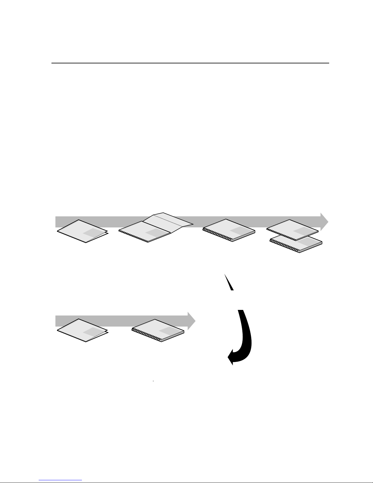
Using the Profile XP Documentation Set
This manual is part of a full set of support documentation for the Profile XP Media
Platform. The following illustrates how to use the Profile XP documentation
depending on the task you are performing.
Profile XP
Manual
F
a
m
i
l
y
o
f
X
P
S
e
r
i
e
s
Grass Valley Group
Profile XP
Manual
F
a
m
i
l
y
o
f
X
P
S
e
r
i
e
s
Grass Valley Group
Profile XP
Manual
F
a
m
i
l
y
o
f
X
P
S
e
r
i
e
s
Grass Valley Group
Profile XP
Manual
F
a
m
i
l
y
o
f
X
P
S
e
r
i
e
s
Grass Valley Group
0624-39
Profile XP
Manual
F
a
m
i
l
y
o
f
X
P
S
e
r
i
e
s
Grass Valley Group
Profile XP
Manual
F
a
m
i
ly
o
f
X
P
S
e
r
i
e
s
Grass Valley Group
Release Notes
Path for the Installer
Path for the Operator
System Guide
User Manuals
Other Manuals
Contains the latest
information about Profile XP
hardware and software
shipped with your system.
Profile XP
Manual
F
a
m
i
ly
o
f
X
P
S
e
r
ie
s
Grass Valley Group
Release Notes
Contains the latest
information about Profile XP
hardware and software
shipped with your system.
Installation Guide
Contains essential steps for
installing your Profile XP
system using factory
default settings.
Contains complete instructions for using
Profile applications. These manuals include:
-
Profile XP User Manual
- ContentShare Explorer User Manual
- Other user manuals you received with
Installers consult
the User Manuals
as needed.
These manuals include:
-
PFC500 Instruction Man
u
- Profile XP Service Manu
a
with NetCentral.
Contains the product description
and step-by-step instructions for
modifying system settings.
Page 12

12 PFC 500/E Instruction Manual 2 December 1999
Manual Descriptions
• Installation Guide (for your Profile XP Model) This guide provides step-by-step
instructions for installing the Profile XP Media Platfor m using factory default
settings for all record/play channels. Factory default settings are indicated within
the guide. After installing the Profile XP system using this installation guide, you
can refer to this Profile XP System Guide to customize system settings for your
installati on.
•
Profile XP System Guide This guide provide s all the information you need to go
beyond facto ry default settings and customize your system’s comf iguration to meet
your site-specific needs. This guide also provides an overvie w of your Profile XP
system, and provides all the spscifications you ne ed to integrate the Profile XP
Media Platform into your operation.
• Profile XP User Manual Contains complete instructions for using Profile
applications to operate the Profile XP Media Platform.
•
Profile XP Service with NetCentral Manual Contains information for servici ng
the Profile XP Media Platform, and include s procedures for the following tasks:
- Problem analysis using symptom, pr oblem, solution tables.
- Running diagnostics locally and remotely
- Set up and operation of Portals remote monitoring software.
- Replacing field replaceable units.
•
Profile XP Release Notes Contains the latest information about the Profile
hardware and the software release shipped on your system. This information
includes software specif ications and requirements, fea tur e changes from the
previous releases, helpful system administrative information, and any known
problems.
• PFC 500/E Instruction Manual
Contains information f or servicing the Profile XP
Fibre Channel RAID Storage Chassis (PFC 500/E) including step-by-step
procedures for repla cing field replaceable units.
Page 13

How this manual is organized
2 December 1999 PFC 500/E Instructi on Manual 13
How this manual is organized
The PFC500/E Instruction Manual is organized around the tasks you’ll be
performing to insta ll and ser vice your Fibr e Channel RAID Storage System. You can
see this refle cted in the chapter t itles c hosen f or t his manu al. The foll owing i dentif ies
and describes the chapters included in this manual:
Chapter 1 - About the PFC500/E
Introduces the Profile XP Fibre Channel RAID Storage Chassis (PFC500) and the
RAID Expansion Chassis (PFC500E). You can read this chapter to get familiar with
the RAID Storage Chassis key features and components.
Chapter 2 - Installing a PFC500/E
Describes how to install a RAID Storage Chassis and RAID Expansion Chassis,
including rack mounting. Refer to the Profile XP System Guide for connection and
configuration information.
Chapter 3 - Servicing and upgrading a PFC500/E
Describes how to replace CRUs , such as disk modul es, and add disk modules and
redundant CRUs.
Appendix A - Technical specifications and operating limits
This appendix consists of electrical and environmental specifications.
Glossary
The Glossary explains terms used throughout this manual.
Page 14

14 PFC 500/E Instruction Manual 2 December 1999
Getting more information
In addition to printed documents, Profile XP product information is avai lable in
on-line manuals. Use these as additional sources for information.
On-line manuals
Electronic ver sions of the following manuals are located on the system drive of your
Profile XP Media Platform and on the Profile XP software CD-ROM.
• Installat ion Guide (for your mode l )
• Profile XP System Guide
• Profile XP User Manual
• Profile XP Service with NetCent ral Manual
• PFC 500/E Instruction Manual
• Profile XP Release Notes
You can view these m anuals using Adobe Acrobat Reade r which is al so pre-in stalled
on your Profile XP system.
Page 15

On-line manuals
2 December 1999 PFC 500/E Instructi on Manual 15
Grass Valley Group Product Support
You can get technical assista nc e, check on the status of pr oblems, or report new problems by
contacting our Product Sup port Group.
United States and Canada
Monday–Friday 5:30AM–5:00PM Pa cific Time
(800) 547-8949
Europe
Monday–Friday 9:00AM–5:30PM
Asia and South America
World Wide
24-hour Emergency Hotline (530) 478-4148 (Contract and warranty customers)
World Wide Web http://www.grassvalleygroup.com
FTP Site ftp.grassvalleygroup.com
Users Group profile-users@grassvalleygroup.com
France 01 69 86 83 47 United Ki ngdom 01628 405830
Germany 0221 9477 446 Other +44 1628 405840
Italy 02 25086606
Australia
- from overseas
02-9888 0100
61-2-9888 0100
Japan 81-3-3448-3111
Korea 82-2-528-5299
Beijing 86-10-62351230
ext. 711
Mexico 52-5-666-6333
Singapore 65-356-3900
Brazil 55-11-3741-8422 Taiwan 886-2-27571571
Hong Kong 852-25856655
Page 16

16 PFC 500/E Instruction Manual 2 December 1999
Page 17
2 December 1999 PFC 500/E Instructi on Manual 17
Chapter
1
About the PFC500/E
This chapter introduces the Profile XP Fibre Channel RAID Storage Chassis. Topics
are :
• PFC 500/E components
•Enclosure
• RAID Contro ll ers (RC s )
• Disk modules
• Power supplies
• Drive fan pack
• Configurations
The PFC500 is an intelligent, highly avail able, high performance, high capacity
storage system tha t uses a Fibre Channel Ar bitrated Loop (FC- AL) as its inter connect
interface. Its modular, s cala ble design provides additional disk storage as yo ur needs
increase.
Using its FC-AL int erface, with simple FC-AL s erial cablin g, an PFC500 can support
up to two PFC500E RAID Expansion Chassis. A PFC500E is a basic chassis without
a RAID controller (RC). The PFC500 and two PFC 500Es support up to 30 disk
modules in a single disk-arr ay storage system. You can place the PFC500Es in the
same cabinet as the PFC500, in a separate cabinet, or in two separate cabinets.
An PFC500 connects to a Profile XP Media Platfor m using the server’s Fi bre Channel
Disk adapter (F C ad ap ter).
Throughout this m anual, the term PFC500/E is used to refer to either the PFC500 or
the PFC500E interchangeably.
Page 18

Chapter 1 About the PFC500/E
18 PFC 500/E Instruction Manual 2 December 1999
PFC500/ E components
The PFC500/E components are:
• A sheet-metal chassis with a midplane and front door
• One or two RAID controllers (PFC500 only)
• One or two Link Control cards (PFC500E only)
• As many as ten Fibre Channel disk modules
• One or two power supplies
• One drive fan pack
Any unoccupied slot (RAID control ler, disk module, or power supply) has a filler
module to maintain ai r flow and compliance with e lectromagnetic interference (E MI)
standards.
The RCs, disk modules, power supplies, fan packs, and filler modules are
customer-replaceable units (CRUs), which you can a dd or repl ace without t ools while
the PFC500/E is powered up.
The optional high availability features for an PFC500/E are
• second RC (PFC500 only)
• second power supply
A second RC p rovides conti nued access to the P FC500 and any connec ted PFC500Es
if the first RC fail s. Adding a second RC to the same chassis is not int ended to increase
performance, but rather to add red undancy
. Refer to the Profile XP System Guide for
detailed connecti on, configuration, and performance information.
The disk drives are FC-AL compliant and suppor t dual-port FC-AL interconnects
through the two RCs and their cabling.
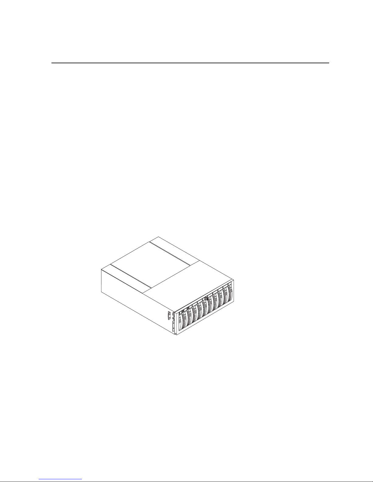
Chassis
The chassis is a sheet-metal housing with a front panel, a midplane, front door, and
slots for the RCs, disk modules, power supplies, and the fan pack.
The following figures show the PFC500/E components. Details on each component
follow the figures. If the chassis provides slots for two identical c omponents, the
component in slot A is called component-name A. If there is a second component, it
is in slot B and is called component-nameB, as follows.
If you have one power supply, it can be in either slot A or slot B. If you have one
RAID controller, it can be in either slot A or B.
Component Name in slot A Name in slot B
RAID Controller RC A RC B
Po wer supply PS A PS B
Page 19
Chassis
2 December 1999 PFC 500/E Instructi on Manual 19
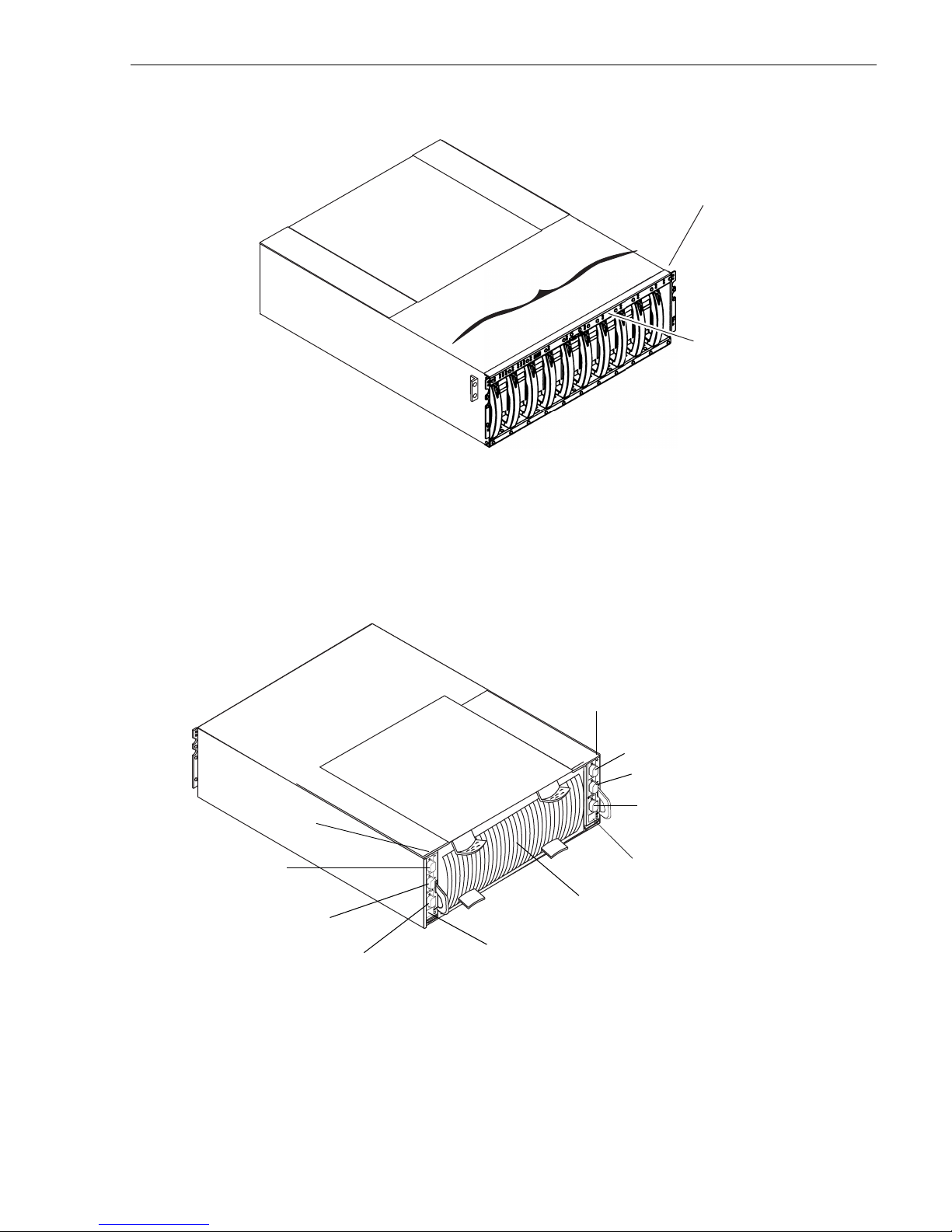
n1
n3
n7
n9
n0
n2
n4
n5
n6
n8
D
i
s
k
m
o
d
u
l
e
s
*
* n is the chassis address (CA) set on the front panel at
installation. It must be set to 0 for a
PFC500. All other CA
values are invalid for a
PFC 500. T h e d is k mo d ul e ID is th e
chassis address and the module ID (0-9) within the chassis. In
a
PFC500, the ID for the right most disk module is 09.
Front panel
Front panel with door
removed for clarity.
A
B
E
X
P
A
B
E
X
P
Serial port
Serial port
Drive fan pack
Port A
Port B
RC B
RC A
Expansion (EXP) port
Expansion (EXP) port
Port B
Port A
Page 20
Chapter 1 About the PFC500/E
20 PFC 500/E Instruction Manual 2 December 1999
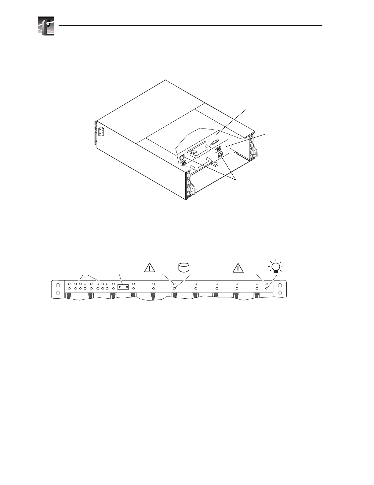
The front panel cont ains the chassis add ress (CA) light, two status lights for each disk
module slot, and two status lights. All lights are visible with the front door closed.
The chassis address light displays the chassis address setting for the PFC500. The
PFC 500 must have an CA of 0. You must set that CA using the chassis address
switches, as explained in Chapter 2.
The status lights are described in the “Monitoring PFC500/E status” on page 40.
Midplane
The midplane di stributes power and signals to all the c hassis components. All CRUs
except the fan packs plug directly into midplane connectors.
A
B
E
X
P
A
B
E
X
P
Power cord
connectors
Power supply
in slot A
Power supply
in slot B
0
12345
10
678910
11
2 3 4 5 6 7 8 9
Chassis
address lights
PFC 500/E status lights
Disk module status lights
(two per module)
System
Check
Power
Disk
check
0
Disk
Active
Chassis
address switch
(not visible with
door closed)
Page 21
Front door
2 December 1999 PFC 500/E Instructi on Manual 21
Front door
The front door has a locking latch and an EMI shield. The latch is a push button with
a removable locking key that you can use in any PFC500 or PFC500E. When the door
is open, you can remove or install disk modules.
IMPORTANT: The front door must be closed for the PFC500/E to be EMI
compliant. Opening the door to access the disk modules is a service procedure.
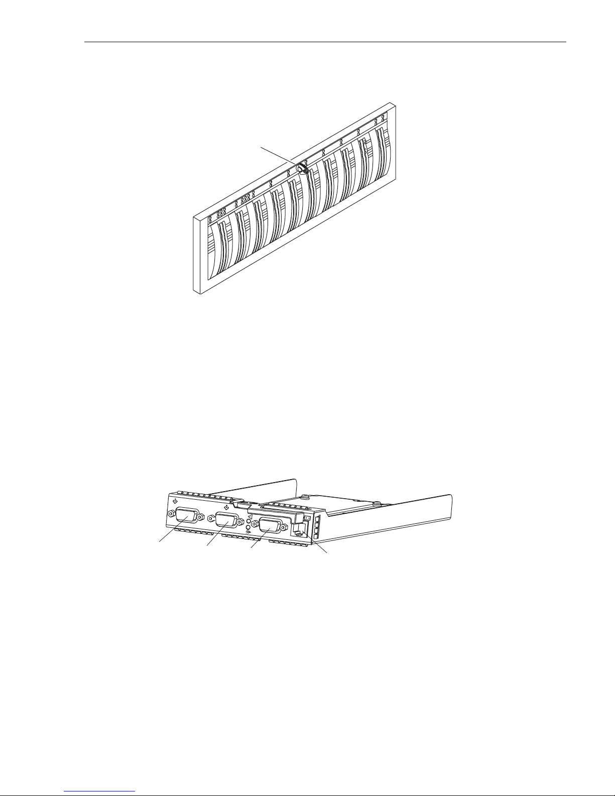
RAID Controllers (RCs)
The RC is the PFC500’s intelligent component. It defines the PFC500 and
differentiates the
PFC500 from a PFC500E. An RC is a printed-circuit board
with one dual in-line me mo ry mo dule (DIM M), a bezel with status lights, and
securin g la tc he s .
The RC has three Fibre Channel ports. Port A and Port B are for connecting to a
Profile XP Media Platform. The expansion connector (EXP) is for connecting to a
PFC500E. The port interface i s called the RC front en d. It can connect to a Profile XP
Media Platform’s Fibre Channel storage board. You set an RC’s FC-AL address ID
using rotary switches.
The RC connects to disk modules in the same chassis via an internal FC-AL. The
expansion port extends the internal FC-AL to the corresponding link control car d
(LCC) in the PFC 500E chassis. This FC-AL is referred to as the RC back end.
An RC also has an RJ-type connector for serial co mmunications with a console.
Locking latch
with key
B
E
X
P
expansion (EXP) port
port B
port A
serial connection
Page 22
Chapter 1 About the PFC500/E
22 PFC 500/E Instruction Manual 2 December 1999
Each RC has two status li ghts visible from the rear of the PFC500/E. For the meaning
of these lights, see “Monitoring PFC 500/E status” on page 40.
Storage-syste m read caching requires one RC, and mirrored storage-system write
caching requires two RCs. If an PFC500 has one RC, you can install a second one
while the PFC500 is running. When both RCs ar e installed, you can re place either R C
while the PFC500 is running. You should never attempt to replace any of the RC’s
components, except the memory modules.
Disk modules
Each disk module consists of a Fibre Channel disk drive in a carrier assembly. You
can add or remove a disk module while the PFC500/E is powered up.
Disk drives
The disk drives are 3.5-inch FC-AL drives that conform to the following standards:
• SFF-8045
• Fibre Channel Arbitrated Loop (FC-AL)
• FC-AL Private Loop Direct Atta ch (PLDA) profile
The disk module slots in the chassis accommodate drives with heights of either
1.0 inch (2.54 cm) or 1.6 inches (4.06 cm). You ca n combine approved drives of either
height, and from different manufacturers, within the same PFC500/E, subject to the
restriction s imposed by the Licensed Internal Code (LIC) running in the PFC500’s
RCs.
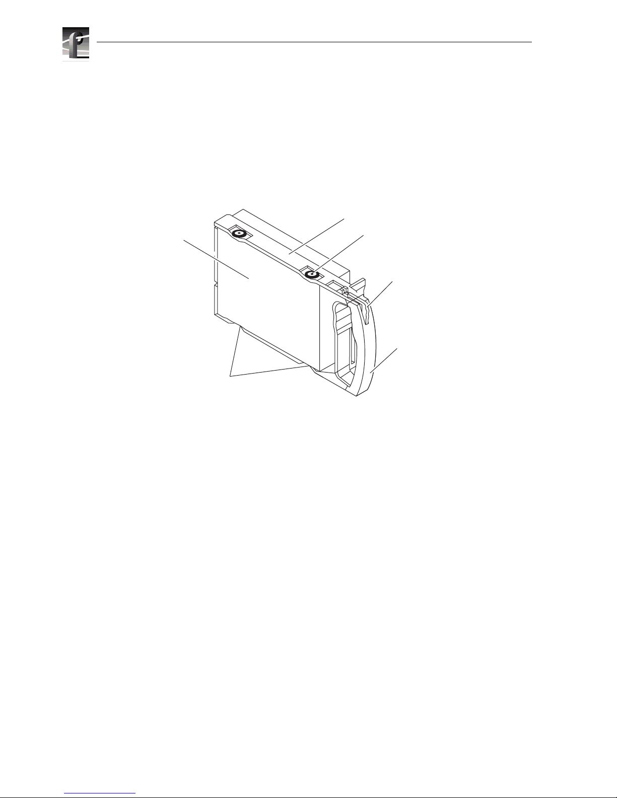
Drive carrier
The disk-drive carrier is a plastic assembly that slides into the chassis slot guides and
midplane connectors. It has a handle with a latch and electrostatic discha rge (ESD)
clips, which connect to the drive’s head-disk assembly. The latch holds the disk
module in place to ensure proper connection with the midplane.
Disk drive
Latch
Shock mount (4)
Carrier
Handle
ESD clip (2)
Page 23
Power supplies (PSs)
2 December 1999 PFC 500/E Instructi on Manual 23
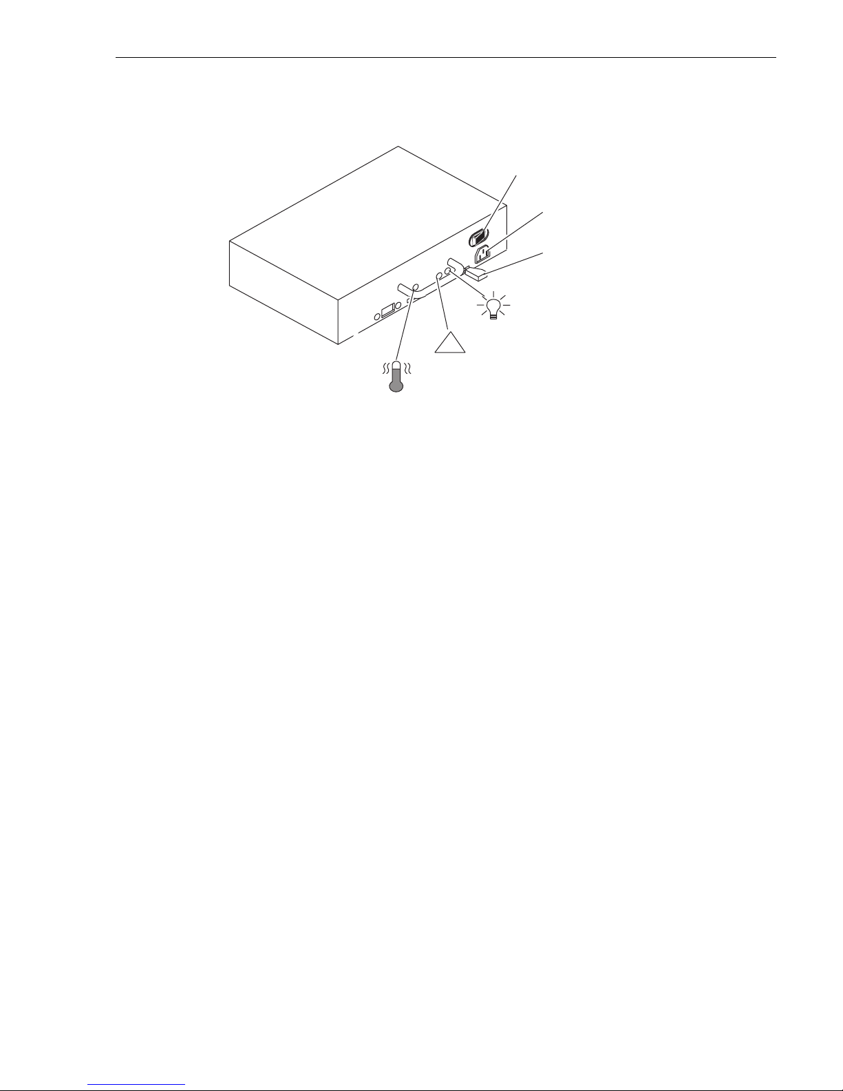
Power supplies (PSs)
The power supplies are locate d behind the drive fan pack. With two power supplies,
the top supply is installed inverted with respect to the bottom supply.
Each power supply is an auto -ranging, power-fa ctor-cor recte d, multi -output, off-li ne
converter with its own line cord and on/off switch. Each supply supports a fully
configured PF C500 and shares load current s with t he other s upply, if it is present. The
drive voltage lines have individual soft-start switches that protect the disk drives if
you install them wh ile th e PFC500/E is powered up. A dis k wit h power- relate d fault s
will not adversely affe ct the operation of any other disk.
Each power supply has status light s. The se status lights are partially vis ible through
the drive fan pa ck, and fully vi sible with the dr ive fan pack remove d. The status lig hts
are described in the “Monitoring PFC500/E status” on page 40.
A latch on the power supply locks it into place to ensure proper connection to the
midplane. You can add or remove one power supply in a highly available P FC500/E
while the PFC500/E is powered up.
On/Off switch and
circuit breaker
Latch
Active light
(green)
Ac line cord
connector
Check light
(amber)
!
Cooling Check
light (amber)
Page 24
Chapter 1 About the PFC500/E
24 PFC 500/E Instruction Manual 2 December 1999
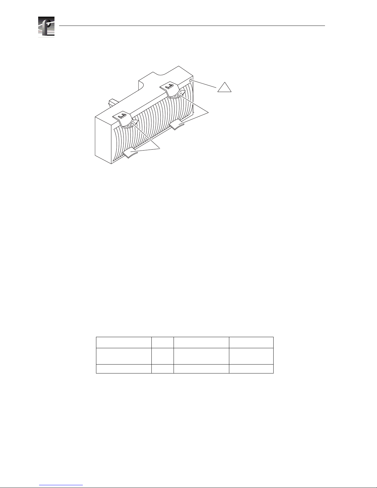
Drive fan pack
The drive f an pack cools the disk modules a nd RCs i n the PFC500. The drive fan pack
contains thre e fans that draw ambient r oom air thr ough the fr ont door, across the dr ive
modules, and through the midplane and power suppl ies. The drive fan pa ck connects
directly to both power supplies, and either supply can power it. The fans operate at a
lower voltage and spe ed during normal operatio n to minimize acoustic noi se. If a fan
fails, the volt age and spee d of t he remai ning fans inc rease to c ompensate, re sulti ng in
higher acoustic noise.
One status light on the driv e fan pack indicat es status. The status li ght is desc ribed in
the “Monitoring PFC500 status” section of Chapter 3.
Latches on the drive fan pack hold the pack in place.
IMPORTANT: You can remove the driv e fan pack while the PFC500 is powered up.
While the pack is removed, the Cooling Check light on each power supply flashes.
If the pack is removed for more than approximately two minutes, the disk module s
power down and the RCs go into standby mode. When you re-install the drive fan
pack, the disk modules power up and the RCs go into active mode.
Configurations
The PFC 500 minimum and maximum configurations are as follows.
The maximum configuratio n provides the mos t redundancy, an d therefore the h ighest
degree of system availability. The fan pack provides redundant cooling for any
configuration.
What next?
Continue to the next chapter, which tells how to install a PFC 500/E.
Configuration RCs Power Suppli es Disk Modules
minimum 1
2
1
1
5
5
maximum 2 2 10
Check light
(amber)
Latches
Latches
!
Page 25

2 December 1999 PFC 500/E Instructi on Manual 25
Chapter
2
Installing a PFC500/E
This chapter desc ribes the Profile XP Fibre Channel R AID Storage Chassis (P FC500/E)
installation requirements and procedures. Major topics are:
•Requirements
• Rack mounting a PFC500/E
• PFC500/E powerup and initialization
• PFC 500/E powerdown
• Binding disk modules into groups
Requirements
This section explains site, cabling, and addressing requirements.
Site requirements
For proper PFC500/E operation, the installation site must conform to certain
environmental specifications. These are detailed below and in Appendix A.
Power
To determine a PFC500/E’s power requirements, use the power rating on the chassis
label. This rating is the maximum power required for a fully loaded chassis. The input
current, power (VA), and diss ipation for the PFC500/E are based on the maximum
capability of the power supplie s and cooling system to provide internally regulated
power. Typical values will be less depending on the number and manufacturer of disk
drives and activity le vel. These values represent either the values for the power cord of
an PFC500/E with a single power supply, or the total values shared by the line cords of
two power supplies in the same PFC 500/E, with the division between the power cords
and supplies at the current sharing r atio. If one of the two power supplies fails, the
remaining suppl y and cord su pport the full load. You must use a r ack mount c abinet with
ac power distri bution , and h ave mai n branch ac distr ibut ion that can handle the se va lues
for the number of PFC500s and PFC500Es that you will interconnect.
Cooling
The ambient temperature specification is measured at the front door inlet. The site must
have air condit ioning of the correct si ze and pla cement to mainta in the specifie d ambient
temperature range . The air conditi oning must be able to handle the BTU requir ements of
the PFC500s and any connected PFC500Es.
Page 26

Chapter 2 Installing a PFC500/E
26 PFC 500/E Instruction Manual 2 December 1999
Cabling requirements
You mst use copper cables for the FC-AL connections between the RCs and the server
adapters or hubs. You should use a common ground distribution grid for all
interconn ected d evi ces.
IMPORTANT: You must use a copper c able only (not an optical cable) to connect
a PFC500 to a PFC500E.
Any copper cables you use must meet the appropriate standards for 1-Gbaud FC-AL
loops. Such cables are fully shielded, twin-axial, full-duplex cables with DB-9
connectors. Cable s greater than 10 mete rs must be equaliz ed; cables equal to or less than
10 meters do not need to be equalized.
PFC500 and PFC500E interconnections shoul d maint ain LCC c onsiste ncy. Th at is, one
FC loop should conne ct the PFC500’s RC A and each PFC500E’s LCC A. The other FC
loop should connect the PFC500/E’s RC B and each PFC500E’s LCC B.
Do not leave an unus ed (that i s, dangl ing) c able connec ted to an R C port bec ause it may
cause excess noise on the loop.
Addressin g re qu ir eme nt s
There are two addresse s for the PFC500: the Fibre Channel Arbitrated Loop addres s ID
(FC-AL address ID) and the chassis addre ss.
FC-AL address ID
Each node (such as an RC) on the Fibre Channel front-end loop mus t have a unique
FC-AL address ID. The FC-AL protocol translates the FC-AL address ID into an 8-bit
arbitrated loop physic al address (ALPA). You set the RC FC-AL address ID using
switches, as explained la ter in this chapter. If your PFC500 has a second, redundant RC,
it should be set to the same FC-AL address ID as the primary FC.
Chassis address (CA)
Each PFC500 and PFC500E on a back-end loop needs a unique chassis address (CA)
that identifie s the chassis and determines dis k module addresses. The PFC500 must have
an CA of 0. You must set that CA using the chassis address switches, as explained later
in this chapter. If you cable any PFC500Es to the PFC500, you might want to set the
nearest PFC500E’s CA to 1, and the next to 2. The chassis add ress is dis pla yed in lig hts
visible behind the front door .
Page 27

Installing a PFC500/E in a cabinet
2 December 1999 PFC 500/E Instructi on Manual 27
Installing a PFC500/E in a cabinet
The cabinet in which you will install the PFC500/E(s) must have a full earth ground to
provide reliable grounding. Also, the cabinet should have its own switchable power
distribution. If any PFC500/E you will install has two power supplies, we suggest that
you use a cabinet that has dual power distribution units, one on each side.
>>> WARNING: The rack mount PFC500/E is heavy and should be installed into a
rack by two people. To avoid personal injury and/or damage to the equipment, do
not attempt to lif t and install the PFC500/E into a rack without help from another
person.
We recommend that you use cabinet anti-tip devices, especially if you are installing or
removing a PFC500/E in the upper half of the cabinet when the lower half is empty.
You install each PFC500/E on two L-shaped mounting rails connected to the cabinet’s
vertical channels. The PFC500/E mounting rails attach to the cabinet only, and do not
have components which attach to the RAID chassis.
Rack-mounting the PFC500/E chassis consists of:
1. Determining the rail mounting positions in the cabinet.
2. Attaching the mounting rails to the cabinet.
3. Sliding the PFC500/E chassis onto the mounting rails.
4. Setting addresses and connecting cables.
The following sections describe these operations.
Determining the rail mounting positions
The following table lists the heights of the PFC 500 and the PFC500E. Use these
measurements to determine the position of your RAID devices in your cabinet.
NOTE: Because the RAID storage unit s are each 3.5 U hi gh, a 0.5 U open space is
created if you install one of these units immediately below your Profile XP Media
Platform. You can fill this gap wi th a 1/ 2 U fill er, w hich at taches t o the chass is, no t
to the cabinet channels.
Device Height
Number of cabinet
channel holes,
starting U-aligned
PFC500 RAID Storage Chassis 3.5. U, 6-1/8 in,
15.6 cm
10
PFC 500E RAID Expansion
Chassis
3.5. U, 6- 1/8 in,
15.6 cm
10
Page 28

Chapter 2 Installing a PFC500/E
28 PFC 500/E Instruction Manual 2 December 1999
The following illustration shows the baselines of different devices in a cabinet.
Review your plan to make sure all devices will fit in the cabinet and also review any
requirements for filler panels.
1/2in
5/8in
5/8in
1/2in
5/8in
5/8in
1/2in
5/8in
5/8in
1/2in
5/8in
5/8in
1/2in
5/8in
5/8in
1/2in
5/8in
5/8in
1/2in
5/8in
5/8in
1/2in
1U device
3.5U device
6.5U device
Baseline of next device
Baseline of next device
Baseline of next device
Baseline of device at a
U-aligned position, between
two holes 1/2in apart.
Pre drilled holes for
rail installation
6.5U
6U
5U
3.5U
3U
2U
1U
4U
Page 29

Attaching the mounting rails
2 December 1999 PFC 500/E Instructi on Manual 29
Attaching the mounting rail s
Once you have determined the positions for the mounting rails, you can attach them to
the cabinet. Each rail has thre aded nuts on its front flange. You can install any rail in a
U-aligned or U-nonalig ned position.
1. For each device, attach the rails to the front channels as follows.
A. Align the base of the left rail with the
baseline and use two screws to
attach the front of the left rail loosely
to the cabinet’s front channel.
Baseline
B. Align the base of the right rail with
the baseline and use two screws to
attach the front of the right rail
loosely to the cabinet’s front channel.
DPE rails
Baseline
Page 30

Chapter 2 Installing a PFC500/E
30 PFC 500/E Instruction Manual 2 December 1999
2. Attach the rails to the middle channel, as shown next.
If you want to use one or more filler panels for esthetic purposes, attach them after
installing the devices in the cabinet.
Sliding PFC500/E onto rails
To install PFC500/Es on the mounting rails in the cabinet
1. Attach the cl ip of the E SD wri stban d (str ap ) to bare metal on the cabin et , and put
the wristband around your wrist with the metal button against your skin.
2. Lift the PFC500/E, and from the front of the cabinet, slide the PFC500/E onto the
lowest rails. Brackets on the rear of the rails fit into cutouts on the PFC500/E.
Middle channel,
view from front
of cabinet
C.
Tighten all screws that fasten the rails to the channels.
Middle channel,
view from front
of cabinet
B.
Use two screws to fasten the back of the rail to the clip nuts.
A.
Push the rail away from the middle channel and slide clip nuts onto the
channel, into the channel holes that align with the rail holes. The
surface of the channel you use depends on the type of rail.
Page 31

Sliding PFC500/E onto rails
2 December 1999 PFC 500/E Instructi on Manual 31
3. Open the PFC500/E front door as shown here.
4. Secure the PFC500/E to the vertical channels of the cabinet as shown here.
Latch
Key
If the door is locked
• Insert the key in the door’s latch.
• Turn the key 180
o
clockwise.
• Remove the key, if desired. (If you
do not remove the key, it may fall
to the floor after you open the
door.)
• Press the door latch.
• Lower the door unt il it i s perpendi cular
to the font of the chassis.
CAUTION: Do not force the door open.
If the door snaps off the hinges, re-install it by positioning it at a
45
o
angle to the chassis and snapping it into the hinge openings.
Latch
NOTE: Only one hole in the chassis bracket aligns with
a mounting hole on the cabinet. The mounting hole you
use depends on where the rails are mounted in the cabinet.
Fasten the front of the enclosure to
the front mounting holes in the cabinet
using two screws (one per side)
Page 32

Chapter 2 Installing a PFC500/E
32 PFC 500/E Instruction Manual 2 December 1999
5. Close the PFC500/E front door, as shown here.
IMPORTANT: The door must be closed for EMI compliance. Open the door only
to service the PFC500/E.
A. Raise the door until it
latches into place.
B. If desired, lock the door as follows:
• Insert the key into the door latch.
• Turn the key 180
o
counterclockwise.
• Remove the key, if desir ed.
Latch
Latch
Key
Page 33

Setting addresses and connecting cables
2 December 1999 PFC 500/E Instructi on Manual 33
Setting addresses and connecting cables
You must now set FC-AL address ID on the RAID controllers, set the chassis ID,
connect Fibre Channel cable s, and connect power cables. Refer to the Profil e XP System
Guide for the settings required for your installation.
1. At the back of the PFC500 chassis, remove each RC from its slot as shown below.
2. For each RC, set the FC-AL address ID using the FC-AL ID switches on the RC
printed circuit board.
Each node (such as an RC) on a Fibre Channel front-end loop must have a unique
FC-AL address ID. The FC-AL protocol translates the FC-AL address ID into an
8-bit arbitrate d loop physical address (ALPA).
IMPORTANT: Each RC’s FC-AL I D must be unique from al l other F C devic es on
that same FC-AL loop.
The valid FC-AL a ddress ID range is a number 0 through 125 decimal, which is 0
through 7D hexadecimal. The following figures and table locate the switches an d
show how to select ID numbers using them.
A
B
E
X
P
A
B
EXP
Latch up
A. Pull up the latch on the RC.
B. Grasp the RC and gent ly
pull it out of the slot
B
E
X
P
Location of switches
Page 34

Chapter 2 Installing a PFC500/E
34 PFC 500/E Instruction Manual 2 December 1999
RC FC-AL address ID switches
3. Set the PFC500’s chassis addr ess ( CA) switc h to 0 usi ng t he tip of a p en or a pape r
clip as shown in the following illu stration.
To access the CA switch, you must open the PFC500/E’s front door. The chassis
address, referred to as the back-end address, identifies the PFC500/E and
determines disk module addresses. The PFC 500 chassis address must be set to 0.
For address ID Set top switch to Set bottom switch to
00 0
10 1
.
.
.
.
.
.
.
.
.
15 0 F
16 1 0
.
.
.
.
.
.
.
.
.
29 1 D
Chassis
address lights
Increment button
Push to increase address.
Decrement button
Push to decrease address.
Address
switch
NOTE: The address
switch has 16 positions, 12 are marked
0 through 11 and the
remaining 4 are
marked with a dash
(-). A dash position
is equivalent to the 0
position.
00
1
2
3
4
5
123
0
6
7
8
9
10
11
0
Page 35

Setting addresses and connecting cables
2 December 1999 PFC 500/E Instructi on Manual 35
4. Reinstall each RC in its slot as shown below.
5. Remove the drive fan pack as shown below.
A
B
EXP
A
B
EXP
A. Pull up the latch on the RC.
B. Align the RC with the guide on the slot.
C. Gently slide the RC into the slot.
D. Push down the latch until
the RC is fully seated in
the slot.
Latch up
Latch down
A
B
E
X
P
A. Grasp the latches on the drive fan pack.
B. Squeeze the lat ches together and pull the
fan pack from the chassis.
Page 36

Chapter 2 Installing a PFC500/E
36 PFC 500/E Instruction Manual 2 December 1999
6. From the back of the cabinet, plug the ac line cord into each power supply a nd turn
on the supply’s power, as shown next.
7. Re-install the dri ve fan pack in the back of the PFC500/E.
You can install the drive fan pack in eithe r horizontal position. However, for a
consistent image with all PFC500/Es, we recommend you install it with the status
light in the upper right corner as shown below.
A
B
E
X
P
A
B
E
X
P
A
B
E
X
P
A
B
E
X
P
Bottom power supply
Top power supply
ac power cord
(right-angle pl ug)
Channel
ac inlet
Power switch and
circuit breaker
Power switch and
circuit breaker
ac inlet
Channel
ac power cord
(right-angle plug)
A. Insert the right -angle plug on the ac line cord in to the supply’s ac inlet
For each power supply:
B. Route the cord along the power supply to the side of the chassis.
IMPORTANT: The cord must not occupy the drive fan pack space.
C. Bend the cord into a U shape and slide the U into the channel so the end of
the cable comes out of t he channel at the back of the chassis.
D. Plug the end of the cord into one of the cabinet’s power out lets.
E. Set the supply’s power switch to the on (1) position.
A
B
E
X
P
A. Grasp the latches on the
drive fan pack.
B. Squeeze the latches
together and gent ly push
the fan pack into the
chassis until it clicks in
place.
Page 37

Setting addresses and connecting cables
2 December 1999 PFC 500/E Instructi on Manual 37
8. Attach the Fibre Channel cable from the Profile XP Media Platform Fibr e Channel
Disk board to the RC’s A port. Use a copper cable as shown here
IMPORT ANT: Do no t leav e an unus ed (t hat is, dangli ng) ca ble co nnect ed to an RC
port because it may cause excess noise on the loop.
9. To expand this PFC500, cable its EXP connector to the corresponding P FC500E’s
PRI (primary) connector as shown here.
10.If the PFC500 has another RC and PFC500Es, connect the PFC500’s other RC and
the PFC500E’s other LCCs as above.
A
B
E
X
P
A
B
E
X
P
A
B
EXP
A. Plug the copper cable from the
Profile XP Media Platform Fibre
Channel Disk board int o port A on the
RC.
B. Tighten the two screws on each
cable connector.
To server, hub, or other FC device
Port A
Port B
RJ-style connector for
serial connec ti on to an
RCS or a console
A
B
E
X
P
A
E
X
P
PRI
IMPORTANT: Do not connect a cable between
an RC in slo t A and an y LCC i n slot B or betwee n
an RC in slot B and any LCC in slot A.
A. Plug one end of the copper cable
onto the expansion (EXP)
connector on the RC in the
PFC500/E.
D. Tighten the two screws on the
cable’s connector.
C. Plug the oth er end of the copper
cable into the pri ma ry (PRI)
connector on the LCC in the
PFC500E.
B. Tighten the two screws on the
cable’s connector.
EXP port
Page 38

Chapter 2 Installing a PFC500/E
38 PFC 500/E Instruction Manual 2 December 1999
11.To connect additional PFC500Es, attach a copper cable between the PFC500E’s
LCC EXP connector and the next PFC500E’s PRI (primary) connector. If this
PFC 500E and the next PFC500E have a second LCC, repeat this step for the
second LCC.
12.Make sure all the slots in the PFC500 and each PFC500E contain either CRUs or
filler modules. At least three disk modules (in slots 0, 1and 2) are required in the
PFC500.
13.In the cabinet, set the main circuit breaker switches to the on position.
The PFC500 and any PFC500Es in the cabinet will power up.
PFC500/E powerup and initialization
The only power switches on a PFC500/E are those on the power supply, which are
normally covered by the drive fan pack. As a result, a PFC500/E is always active.
When ac power is initially applie d to a PFC500/E, the disk drives power up according
to their specifications, and spin up in a specified sequence. The slot spin-up delays are
multiples of 12 seconds. The maximum delay is 84 seconds. The same delays are used
when you insert a drive while an PFC500/E is powered up.
NOTE: Upon powerup, all LUNs are controlled by RAID Controller A if it is
operational. RC B co ntrols LUNs only if RC A fails , and continues to control LUNs
until the next powerup.
PFC500/E powerdown
To turn off power correctly
1. Stop any I/O activity to the PFC500/E.
2. Shut off power to the ac distribution strips that supply the PFC500/E.
The power in the distribution strips may be controlled by a cir cuit breaker located
inside the cabinet (if the cabine t has such breakers) or may be controlled by a
circuit breaker locate d externally to the cabinet.
To turn on power, reverse the steps to powerup the PFC500/E.
Binding disk modules into groups
After cabling an P FC500/E and any PFC500Es, you must bind dis k module s into LUNs
and create a file system using the Profile XP Disk Utility. Refer to the Profile XP System
Guide for more information on confi guring your storage system.
Page 39

2 December 1999 PFC 500/E Instructi on Manual 39
Chapter
3
Servicing and upgrading a PFC500/E
This chapter describes how to monitor PFC500/E status, handle CRUs, and replace
or add a CRU. Topics are
• Hot swapping components
• Monitoring PFC500/E status
• Handling CRUs
• Replacing or adding a disk module
• Removing an RC or an RC filler module
• Installing or removing the RC memory module
• Installing a n RC or RC filler module
• Replacing the drive fan pack
• Replacing or adding a power suppl y
Hot swapping components
The PFC500/E is desi gned for c ontinuous ope ration, a nd it sh ould always be powered
up. You can replace any disk module, redundant RC, or fan pack while the PFC500/
E is running.
During normal PFC500/E operation, all compartment s should contain either a module
or filler, and the front door should be closed. This ensur es EMI compliance and proper
air flow (cooling) within the unit.
The following CRUs are available from Grass Valley Group.
Description Part Number
18GB replacement drive PFC18G
36GB replacement drive PFC36G
RAID Controller (RC) 039-0084-XX
Link Controller Card (LCC) 116-0942-XX
Power supply 119-6314-XX
Fan modul e 119-6315-XX
Rackmount kit 016-1863-00
Fibre Optic Cable, PFC500 to PFC500E 174-4409-00
Page 40

Chapter 3 Servicing and upgrading a PFC500/E
40 PFC 500/E Instruction Manual 2 December 1999
Monitoring PFC500/E status
Status lights on the PFC500/E and its CRUs indicate error conditions . These lights are
visible outside the PFC500/E. Some lights are visible from the front, and others from
the back. The following figure and table describes the status lights.
IMPORTANT: The PFC500 chassis address must be set to 0 (zero)
.
Light Quantity Color Meaning
PFC500/E Powe r
1 Green
On when the PFC500/E is powered up.
PFC500/E System
Check
1 Amber On when any fault conditi on exists.
Disk Active 1 per disk
module slot
Green Off when the disk module slot is empty or
contains a fill er m odule.
Flashing
(mostl y o ff)
when the drive is
powered up but not spinning; this is a
normal part of the spin
-up sequence,
occurring dur ing the spin- up delay of a sl ot.
Flashing
(at a con sta nt ra te)
when the disk
drive is spinning up or spinning down
normally.
On when the drive is spinni ng but not
handling any I/O activity (the ready state).
Flashing
(mostly on
) when the disk drive is
spinning and handling I/O activity.
Disk Check 1 per disk
module slot
Amber On when the disk module is faulty, or as an
indication to remove the drive.
Chassis Address 12 Green The chassis addres s f or the PFC500 must
be set to 0 (zero), the only chassis
address that is valid for the PFC500.
0
12345
10
678910
11
2 3 4 5 6 7 8 9
Chassis
address lights
PFC 500/E status lights
Disk module status lights
(two per module)
System
Check
Power
Disk
check
0
Disk
Active
Chassis
address switch
(not visible with
door closed)
Page 41

Monitoring PFC500/E status
2 December 1999 PFC 500/E Instructi on Manual 41
Status lights visible at the back of the PFC500 /E
If the RC Check light is on, you should look at the other Check light s to determine
which CRU is faulty. If a check light on a CRU remains on, you should replace that
CRU as soon as possible.
If a nonredundant CRU fails in a PFC500, the system may be inoperable while you
replace the CRU. If a redundant CRU fails, high availability will be compromised
until you replace the faul ty CRU.
Light Quantity Color Meaning
Active 1 per RC Green On when the RC is powered up.
RC Check 1 per RC Amber On when either the RC or a Fibre Channe l
connection is faulty.
Power Supply Active 1 per supply Green On when the power supply is ope rating.
Power Supply Check 1 per supply Amber On when the power supply is faulty or is
not receiving ac li ne voltage.
Cooling Check 1 per supply Amber Flashing when either multiple fans in the
drive f an pack are fault y or the drive fan
pack is removed. The RC powers down
the disk driv es and goes into standby
mode when the fault persists for more
than about two minutes.
Drive Fan Pack Check 1 on drive
fan pack
Yellow On when a fan in the drive fan pack is
faulty.
Page 42

Chapter 3 Servicing and upgrading a PFC500/E
42 PFC 500/E Instruction Manual 2 December 1999
Handling CRUs
This section desc ribes the precautions that you must take and the general procedure s
you must follow when removing, installing, and storing CRUs.
Power issues and CRUs
The PFC500/E is designed for continuous oper ation and to be hot repairable. It should
always be powered up. You should replace any disk module, redundant RC,
redundant power supply, or the fan pack while the PFC500/E is running.
Its front door should be closed and each of its compartments sho uld contain a CRU or
filler panel to ensure EMI compliance and proper air flow over the CRUs.
While the PFC500/E is powered up, you can service or replace any CRU. You should
not remove a faulty CRU until you have a replacement available.
IMPORTANT: You can re move the drive fan pac k whi le the PFC500/E is powered
up. While the pack is remove d, the Cooling check ligh t on the power suppl y flashes.
If the pack is r emoved for more than 2 minutes, th e disk modules power down and
the each RC goe s into standby mode. When you r einstall the drive fan pack, t he disk
modules power up and each RC goes into active mode.
Since you can replace or add any CRU without sliding the PFC500/E out of the
cabinet, you do not have to use cabinet anti-tip de vices when you upgrade or servic e
an PFC500/E.
If you need to power down an PFC500/E, refer to the power down procedure on
page 38.
Avoiding electrostatic discharge (ESD ) damage
When you replace or install CRUs, you can inadver tently damage the sensitive
electronic ci rcuits in the equipment by sim ply touching them. Elec trostatic charge that
has accumulated on your body discharge s through the circuits. If the air in the work
area is very dry, running a humidifier in the work area will help decrease the risk of
ESD damage. You must follow the procedures below to prevent damage to the
equipment.
IMPORTANT: Read and understand the following instru ctions.
• Provide enough room to work on the equipment. Clear the work site of any
unnecessary mate rials or materials that na turally buil d up e lectrostatic charge, such
as foam packaging, foam cups, cell ophane wrappers, and similar items.
• Do not remove r eplacem ent or upgrade CRUs from t heir antist atic packaging unti l
you are ready to install them.
• Gather together the ESD kit and all other materials you will need before you
service an PFC500/E. Once servicing begins, you s hould avoid movin g away from
the work site; otherwise , you may build up an electrostatic charge.
• Use the ESD k it when handling any CRU. If an emergency a rises and the ESD kit
is not available, follow the procedures in the “Emergency procedures (without an
ESD kit)” section.
Page 43

Precautions when removing, installing, or storing
2 December 1999 PFC 500/E Instructi on Manual 43
• To use an ESD wristba nd , attac h the clip of the ESD wrist band (st rap) to any ba re
(unpainted) metal on the PFC500/E chassis; then put the wristband around your
wrist with the metal button against your skin.
Emergency procedures (without an ESD kit)
In an emergency when an ESD kit is not available, use the following procedures to
reduce the pos sibil ity of an e lec trostatic disc harg e by ensur in g that your b ody and the
subassembly are at the same electrostatic potential.
IMPORTANT: These procedures are not a substitute for the use of an ESD kit.
Follow them only in the event of an emergency.
• Before touching any CRU, touch a bare (unpaint ed) metal surface of the cabinet or
chassis.
• Before removing any CRU from its antista tic bag , place one hand fi rmly on a bare
metal surfa ce of the chassi s, and at the same time, pick up the CRU while it is still
sealed in the antista tic bag. Once you ha ve done this, do not move a round th e room
or contact other furnis hings, personnel, or surfaces until you have insta lled the
CRU.
• When you remove a CRU from the antistatic bag, avoid touc hing any electronic
components and circuits on it.
• If you must move around the room o r touch other sur faces befo re installin g a CRU,
first place the CRU back in the antistatic bag. When you are ready again to install
the CRU, repeat these procedures.
Precautions when removing, installing, or storing CRUs
Use the precautions list ed below when you remove, handle, or store CRUs.
• Do not remove a faulty CRU until you have a replacement available.
• Handle a CRU only when using an ESD wris tband as follows: atta ch the clip of the
ESD wristband to the ESD bracket or bar e metal on the PFC500/E chassis, and put
the wristband around your wrist with the metal button against your skin.
• Handle CRUs gently. A sudden jar, drop, or vibration can permanently damage a
CRU.
• Never use exces si v e force t o remo v e or ins ta ll a CRU.
• Store a CRU in the anti-static bag and specially designed shipping container in
which you received it . Use that container if you need to ret urn the CRU for repair.
• Maintain the location where you store CRUs within the limits specified in
Appendix A.
Page 44

Chapter 3 Servicing and upgrading a PFC500/E
44 PFC 500/E Instruction Manual 2 December 1999
Replacing or adding a disk module
>>> CAUTIO N: You can destroy a stor a ge sy ste m b eyond recover y if you move th e
wrong drive. The system operator or service person can move a disk module with
the following cautions:
• The disk module must be unbound.
• Moving a module that is part of a LUN to another slot makes all i nformation on the
LUN inaccessible.
• You must remove and insta ll the di sk module whi le the stor age syst em is powered
up.
A disk module must be inserted a ll the way or removed entirely. Do not leave a disk
module partially r emoved except for periods when you are allowing it to spin down.
A disk module being inserted or removed may be damaged by a partially removed
adjacent module.
When replacing multiple disks, observe the following:
• After re moving a disk m odule, wait for the a ctivity l ights on the other disk module s
to resume a steady flicker before removing the next module. The activity lights
show that the LIC (licensed inter nal code) has rediscovered the FC loop.
• After inserting a disk module, wait for the activity lights on the other drives to
resume a steady flicke r before insert ing the next module. As with m odule removal,
the activity lights show tha t the LIC has rediscovered the FC loop.
>>> CAUTION: Handle a disk module gently and use an ESD wristband. Do not remove
a faulty disk module until you have a replacement module (with the same part
number) or a f iller module av ailable. The part nu mber appears on th e top or bottom
of the module. A replacement or add-on disk module should have the same format
(520- or 512-byt e sectors) and the same capacity as the other modules in the chassis .
IMPORTANT: You must open the PFC500/E’s front door to access the disk
modules. The door must be closed for EMI compliance when the PFC500/E is
powered up. Open it only to replace or add a disk module.
Page 45

Replacing or adding a disk module
2 December 1999 PFC 500/E Instructi on Manual 45
3. To unlock and open the front door
If you are adding a new disk module, continue to the disk filler module removal
procedure that follows. If you are replacing a faulty disk module, proceed to the disk
module removal procedure.
Latch
Key
If the door is locked
• Insert the key i n the door’s latch.
• Turn the key 180
o
clockwise.
• Remove the key, if desired. (If you
do not remove the key, it may fall
to the floor after you open the
door.)
• Press the door lat ch.
• Lower the door unt il i t is per pendic ular
to the font of the chassis.
CAUTION: Do not force the door open.
If the door snaps off the hinges, re-install it by positioning it at a
45
o
angle to the chassis and snapping it into the hinge openings.
Latch
Page 46

Chapter 3 Servicing and upgrading a PFC500/E
46 PFC 500/E Instruction Manual 2 December 1999
To remove a disk filler module
Locate the slot where you want to install the disk module, and remove the filler
module, as shown next.
Skip to the disk installa tion procedure (page 47) to install the add-on disk module in
the slot you just emptied.
To remove a disk module
IMPORTANT: If a disk module has been bound into a LUN, do not move it to
another slot unless you do not care about the data on the LUN. Each module has
LUN identifying informat ion written when it is bound. Moving it to another slot can
make information on the original LUN inaccessible.
Generally, you should not remove a disk module unless its amber check light is on.
Remove the disk module from the slot, as shown next.
Continue to the next section to install the replacement disk module.
Latch
A. Grasp the disk filler modul e’s
handle so that your thumb i s on the
latch.
B. Push the latch, and pull the disk
filler module fro m the chassis.
Latch
A. Grasp the disk module’s handle so
that your thumb is on the latc h.
B. If the active light is on steadily, push the
latch, and slowly pull the module about 1
inch (3 cm) from its slot. Wait 30 seconds
for t h e disk to st o p spinning. Th en rem o v e
the module.
If the active light is off or mostly off you do
not need to wait for the disk to stop
spinning. Push the l atch and slowl y pull the
module from its slot.
Page 47

Replacing or adding a disk module
2 December 1999 PFC 500/E Instructi on Manual 47
To install a disk or filler module
1. Gently insert the disk module as follows:
The disk module’s Active light flashes to re f lect the disk’s spin-up sequence. (No
lights flash with a fill er module.)
2. Remove and store the ESD wristband and continue to the next section to close the
front door.
Latch
A. Grasp the disk or filler module’s
handle.
B. Align the module with the guides in
the slot.
C. Gently push the modul e into the
slot until the latch engages.
Page 48

Chapter 3 Servicing and upgrading a PFC500/E
48 PFC 500/E Instruction Manual 2 December 1999
To close and lock the front door
A. Raise the door until it
latches into place.
B. If desired, lock the door as follows:
• Insert the key i nto the
door latch.
• Turn the key 180
o
Latch
Latch
Key
Page 49

Removing an RC or an RC filler module
2 December 1999 PFC 500/E Instructi on Manual 49
Removing an RC or an RC filler module
>>> CAUTION: Handle an RC gently and use an ESD wristband. Do not remove a
faulty RC until you have a replacement module or filler module available.
IMPORTANT: A PFC500 must have at least one RC installed while it is powered
up. Do not remove both RCs while the PFC500 is powered up.
Before removing an RC from a storage system that has caching enabled, you
should disable the stor age-system cache using a utility des cribed in the server setup
manual.
To remove an RC or an RC filler module
1. If you are removing an RC filler module, ignore this step and proceed to step 2 on
the next page; otherwise, remove the cables connected to the RC, as shown here.
IMPORTANT: Note where the cables connect to the RC.
A
B
E
X
P
A
B
E
X
P
A
B
EXP
A. Loosen two screws on
each cable’s connector.
B. Unplug each cable from its
associated RC connector.
Page 50

Chapter 3 Servicing and upgrading a PFC500/E
50 PFC 500/E Instruction Manual 2 December 1999
2. Remove the RC or RC filler module from its slot as shown here.
Continue to the next section to install the memory on the RC.
A
B
E
X
P
A
B
E
X
P
Latch up
A. Pull up the latch on the RC.
B. Grasp the RC and gent ly
pull it out of the slot
Page 51

Installing or removing the RC memory module
2 December 1999 PFC 500/E Instructi on Manual 51
Installing or removing the RC memory module
Although you RC is equippe d with the requi red amount of memory, you may ne ed to
upgrade the memory in the future. Use these intructions to remove or add memory
modules.
To install or remove an RC memory module
1. Read the “Avoiding electrostatic discharge (ESD) damage” secti on
(page 42).
2. Attach the clip of the ESD wristb and to any bare (unpainte d) metal on the PFC500/
E chassis; then put the wristba nd around your wrist with the metal button against
your skin.
3. Remove the memory module (or the new RC board and memory module) from its
packaging, and place it on a static-free work surface.
4. If you are upgrading an RC, remove the RC from the chassi s (page 49), and place
it on a static-free work sur face.
5. On the RC, remove and /or install the DIMM in the approp riate connector as shown
next.
IMPORTANT: A memory module has a notch on its edge near pin
1 so that you can
insert it only one way.
Page 52

Chapter 3 Servicing and upgrading a PFC500/E
52 PFC 500/E Instruction Manual 2 December 1999
IMPORTANT: Depending on the memory size (in megabytes), the PFC500/E RC
memory module can contain chips on only one side or on both sides.
A
B
E
X
P
A. Use your thumbs to
push out on the locking
tabs, and use your
fingers to push the
DIMM forward until it
releases fro m the tabs.
B. Lift the module out of
the connector, and
place it in its own
antistat ic packaging.
Locking tab
Locking tab
Alignment notch
A
B
E
X
P
A. Use your thumbs to
push out on the locking
tabs, and use your
fingers to push the
DIMM forward until it
releases fro m the tabs.
B. Lift the module out of
the connector, and
place it in its own
antistat ic packaging.
Locking tab
Locking tab
Alignment notch
Page 53

Installing or removing the RC memory module
2 December 1999 PFC 500/E Instructi on Manual 53
6. If you want to install the RC, contin ue to the next section.
If you want to ship the RC, store it in its antistatic bag and special shipping
package. Then remove and store the ESD wristband.
A
B
E
X
P
Alignment notch
Locking tab
Locking tab
A. Lift the module out of
its anti stat ic pa ckag ing
and place the module
into the connect or.
C. Use your finger s to
push out on t he locki ng
tabs, and use your
thumbs to push the
module in until seated.
Then engage the tabs.
B. Ensure that the
alignment notch is
correctly orient ed.
Page 54

Chapter 3 Servicing and upgrading a PFC500/E
54 PFC 500/E Instruction Manual 2 December 1999
Installing an RC or an RC filler module
IMPORTANT: If you ar e in stal ling a new/add- on/replac ement RC, e nsure t hat th e
RC memory has been installed before proceed ing to install the RC.
Each RC requires a unique FC-AL address ID on the loop to communicate with the
Profile XP Media Platfor m. If you are installing a replacement RC, set it s address to
be the same as tha t of t he RC y ou re moved. I f yo u ar e inst alling an a dd-on RC, set the
address to a different setting tha n the address of any ot her RC on th e loop. The F C-AL
protocol tran slates the FC-AL address ID into an 8-bit arbit rated loop physical a ddress
(ALPA).
IMPORTANT: Each RC’s FC-AL ID must be unique on the FC-AL loop. If you
have two FC-AL loops, we su ggest a uniq ue FC-AL address ID for e ach RC on both
loops.
The valid FC-AL address ID range is a number 0 through 125 decimal, which is 0
through 7D hexadecimal. The following figures and table locate the switches an d
show how to select ID numbers using them.
IMPORTANT: You must set the FC-AL a ddress ID on th e RC before you insta ll it .
If you are installi ng an RC fille r modul e, ignore step 1 and proc eed t o step 2 on th e
next page.
1. Using the RC FC-AL ID switches, set the FC-AL address ID as shown below.
RC FC-AL address ID switches
B
E
X
P
Location of switches
For address ID Set top switch to Set bottom switch to
00 0
10 1
.
.
.
.
.
.
.
.
.
15 0 F
16 1 0
.
.
.
.
.
.
.
.
.
29 1 D
Page 55

Installing an RC or an RC filler module
2 December 1999 PFC 500/E Instructi on Manual 55
2. Gently insert the RC or RC filler module as shown below.
If you just install ed an RC fille r module, you are done . Remove and st ore the ESD
wristband.
If you just installed a replacement or add-on RC, the RC Active light turns on.
Continue to step 3.
A
B
EXP
A
B
EXP
Latch up
A. Pull up the latch on the RC.
B. Align the RC wit h the guide on the slot.
C. Gently sl ide the RC into the slot.
D. Push down the latch until the
RC is fully seated in the slot.
Latch down
Page 56

Chapter 3 Servicing and upgrading a PFC500/E
56 PFC 500/E Instruction Manual 2 December 1999
3. Install the cables connected to the RC:
4. Remove and store the ESD wristband.
A
B
E
X
P
A
B
E
X
P
A
B
EXP
A. Plug the copper cable(s) from the
server, hub, or other FC device into
port(s) A and/or B on the RC.
B. Tighten the two screws on each
cable connector.
Port A
Port B
To Profile XP Fibre Channel Disk board.
Page 57

Replacing the drive fan pack
2 December 1999 PFC 500/E Instructi on Manual 57
Replacing the drive fan pack
>>> CAUTION: Handle a drive fan pack gently and use an ESD wristband. Do not
remove a fault y drive fan pack until y ou have a re placement unit available . You can
remove the drive fan pack while the PFC500/E is powered up. While the pack is
removed, the Cooling Check light on the power supply flashes. If the pack is
removed for more than two minutes, the disk modules power down and the RC(s)
go into stand by mode. The disk module s power up when you reinstall the drive fan
pack.
To remove the drive fan pack
As soon as the pack is dis connected from each power supply, the drive fan pack Check
light turns of f, if it was not al ready off; the PFC500/E Check light on the front pa nel
turns on, if it was not already on; and the Cooling Check light on each power supply
flashes.
A
B
E
X
P
A. Grasp the latches on the drive fan pack.
B. Squeeze the lat ches together and pull the
fan pack from the chassis.
Page 58

Chapter 3 Servicing and upgrading a PFC500/E
58 PFC 500/E Instruction Manual 2 December 1999
To install the drive fan pack
You can install the drive fan pack in eithe r horizontal orientation. However, we
recommend that you install it with the status light in the upper right corner.
As soon as the pack is in place, the fans start spinning; the PFC500/E Check light
turns off if no other CRUs are faulty, and the Cooling Check light on each power
supply turns off.
A
B
E
X
P
A. Grasp the latches on the
drive fan pack.
B. Squeeze the latches
together and gent ly push
the fan pack into the
chassis until it clicks in
place.
Page 59

Replacing or adding a power supply module
2 December 1999 PFC 500/E Instructi on Manual 59
Replacing or adding a power supply module
>>> CAUTION: To access the power supplies, you must remove the drive fan pack. If
the drive fan pack is removed for more than approximately two minutes, the disk
modules power down and the RCs go into standby mode. The disk modules power
up when you reinstall the drive fan pack.
Handle a power supply gently and use an ESD wristband. Do not remove a power
supply until you have a replacement suppl y or filler module available.
IMPORTANT: If one power supply is off and the other is on, do not turn one on
and immediately turn off the other. Instead, turn one on and wait five seconds
before turning the other off.
If you are adding a ne w power supply, continue to the procedure that follows. If you
are replacing a faulty power supply, proceed to the power-sup ply removal procedur e
as shown on page 61.
Page 60

Chapter 3 Servicing and upgrading a PFC500/E
60 PFC 500/E Instruction Manual 2 December 1999
To remove a power-supply filler module
1. Remove the drive fan pack as shown on page 57.
2. Remove the power-supply filler module as shown.
Continue to the power-supply installation procedure (page 64) to install the add-on
power supply in the slot from which you removed the fille r module.
A
B
E
X
P
A
B
E
X
P
A
B
E
X
P
A
B
E
X
P
A. Push the latches on both sides of
the filler modul e towar ds the ce nter
of the m odul e .
B. Pull the filler module from the slot.
Bottom filler modul e
Latch
(1 per side)
A
B
E
X
P
A
B
E
X
P
A
B
E
X
P
Top filler module
Latch
(1 per side)
A. Push the latches on both sides of
the filler module t oward s the cen ter
of the module.
B. Pull the filler module from the sl ot.
Page 61

Replacing or adding a power supply module
2 December 1999 PFC 500/E Instructi on Manual 61
To remove a power supply
>>> CAUTION: Turn off the power supply before unplugging the power cord fro m the
supply or removing the supply from the chassi s.
1. Remove the drive fan pack as shown on page 57.
2. Turn off the power supply and unplug its ac line cord as shown.
A
B
E
X
P
A
B
E
X
P
A
B
E
X
P
A
B
E
X
P
Bottom power supply
Top power supply
For the power supply to be removed:
A. Set the supply’s power swit ch to the off (0) position.
B. Unplug the ac power cord from the suppl y’s receptacle.
C. Remove the cord from the chassis.
ac power cord
(right-angle pl ug)
ac receptacle
Power switch
Channel
Channel
Power switch
Page 62

Chapter 3 Servicing and upgrading a PFC500/E
62 PFC 500/E Instruction Manual 2 December 1999
3. Remove the power supply as shown here.
A
B
EX
P
A
B
E
X
P
A
B
E
X
P
A
B
E
XP
A. With your thumb, push the latch
up, and then right as far as it
goes.
You may need to brace your
hand against the supply’s
handle.
B. Grasp the handle with one hand,
and gently p ull t he supply from t he
chassis, supporting it with your
other hand.
Latch
Page 63

Replacing or adding a power supply module
2 December 1999 PFC 500/E Instructi on Manual 63
Continue to the power-suppl y installation procedure that follows to install the
replacem ent su p ply.
A
B
E
X
P
A
B
E
X
P
A
B
E
X
P
A
B
E
X
P
A. With your thumb, push the latch
down, and then left as far as it
goes.
You may need to brace your
hand against the suppl y’s
handle.
B. Grasp the handle with one hand,
and gently pull the supply from
the chassis, sup porting it with
your other hand.
Latch
Page 64

Chapter 3 Servicing and upgrading a PFC500/E
64 PFC 500/E Instruction Manual 2 December 1999
To install a power supply
1. Gently insert the new power supply into the chassis, as shown below.
IMPORTANT: The power supply in the top slot is inverted with respect to the power
supply in the bottom slot.
Installing the bottom power supply
A
B
E
X
P
A
B
E
X
P
A
B
E
X
P
A
B
E
X
P
Latch
Slot
A. Make sure that the supp ly’s latch is
as far left in the slot as possible.
B. Align the supply with the chassis slot
and gently push into the slot until the
latch moves to the mi ddle of the slot.
C. With your th umb, pu s h t h e latch righ t
until it snaps up.
You may need to brace your hand
against the suppl y’s handle.
Page 65

Replacing or adding a power supply module
2 December 1999 PFC 500/E Instructi on Manual 65
Installing the top power supply
A
B
E
X
P
A
B
E
X
P
A
B
E
X
P
A
B
E
X
P
Latch
Slot
A. Make sure that the supply’s latch is
as far right in the slot as possible.
B. Align the supply with the chassis slot
and gently push in to the slot until the
latch moves to the middle of the slot.
C. With your thumb, push the latch right
until it snaps down.
You may need to brace your hand
against the supply’s handle.
Page 66

Chapter 3 Servicing and upgrading a PFC500/E
66 PFC 500/E Instruction Manual 2 December 1999
2. Plug the ac powe r cord into t he new supply, a nd turn on the powe r supply as shown
here.
3. Reinstall the dri ve fan pack as shown on page 57.
A
B
E
X
P
A
B
E
X
P
A
B
E
X
P
A
B
E
X
P
Bottom power supply
Top power supply
ac power cord
(right-angle pl ug)
Channel
ac inlet
Power switch and
circuit breaker
Power switch and
circuit breaker
ac inlet
Channel
ac power cord
(right-angle plug)
A. Insert the right -angle plug on the ac line cord in to the supply’s ac inlet
For each power supply:
B. Route the cord along the power supply to the side of the chassis.
IMPORTANT: The cord must not occupy the drive fan pack space.
C. Bend the cord into a U shape and slide the U into the channel so the end of
the cable comes out of t he channel at the back of the chassis.
D. Plug the end of the cord into one of the cabinet’s power out lets.
E. Set the supply’s power switch to the on (1) position.
Page 67

2 December 1999 PFC 500/E Instructi on Manual 67
Appendix
A
Technical specifications and operating
limits
This appendix describes the PFC500/E technical specificati ons, operat ing l imits, and
shipping and storage requirements.
Technical spec ifica tions
Technical specifications include power requirement, size, drive, interface, and
standards information.
ac power requirements
The input current, power (VA), and dissipation per PFC500/E are based on the
maximum capability of the power supplies and cooling system to provide internal
regulated power. Typical values will be less, depending on the number and
manufacturer of disk modules. These values represent either
• the values for the line cord of an PFC500/E with a single power supply, or
• the total values sha red by the line cords of two power supplies in the same iDAE,
with the division between the line cords a nd supplies at the current sharing ratio.
A failure of one of the two po wer supplie s in the i DAE results in the remaini ng supply
and cord supporting the full load. You must use a rackmount cabinet with ac power
distribution, and have main branch ac distribution that can handle the se values for
each iDAE in the cabinet.
Requirement Description
ac line vol tage 100 to 240 Vac +
10%, single phase, 47 to 63 Hz
ac line current 4.0 A max estimate at 100 V (fully configured)
Power consumption 400 VA max estimate (fully configured)
Power dissipation 392 W max estimate (fully configured)
Power factor 0.98 min at full load, low voltage
Heat dissipation
1411x10
3
J/hr (1340 BTU/hr) max esti ma te
In-rush current 25 A max estimat e for 1/2 line cycle, per power sup ply
ac protection 8 A thermal circuit breaker on each power supply
ac inlet type IEC320-C14 appliance coupler
Hold-up time 20 ms min at 50 Hz
Curr ent sh arin g 60% ma x , 4 0% min
Page 68

Chapter A
68 PFC 500/E Instruction Manual 2 December 1999
Size and weight
Drive type
3.5-inch drives, Fibre Channe l inter face, 1.0-inc hes (2.54 c m) or 1.6-inc hes (4.06 c m)
tall.
Disk module address
Each disk module on a Fibre Channel loop has a unique physical a ddress. This address
is derived from the enclosure address (EA, which must be set to 0 for an iDAE) as
follows:
Fibre Channel loop physical address = (10 multiplied by EA) + (slot address)
where the slot address is number of the slo t (0-9) containing the disk module
(numbered from left to right, as viewed from the front of the enclosure).
RC FC-AL interface
Connector - shielded DB-9 receptacle with pinouts as follows.
Item Measurement
Height
5.41 cm (6.07 in)
3.5 NEMA units including mounting hardware
Width 44.5 cm (17.5 in)
Depth
63.27 cm (24 .91 in) front door to back of drive fan pack
60.43 cm (23.79 in) chassis front to back of drive fan pack
57.2 5 cm (2 2. 54 in) rail fr on t to back od drive fan pa ck
Weight 36.0 kg (80.0 lbs) highly available max
1.05 kg (2.3 lbs) disk module
0.68 kg (1.5 lbs) RAID controller or link control card
3.8 kg (8.5 lbs) power supply
1.8 kg (4.0 lbs) drive fan pack
Connector diagram
Pin Signal Defined by
1
2
3
4
5
6
7
8
9
+fc_out
5V
n_mia_fault(active LO)
key
+fc_in
-fc_out
mia_output_disable
gnd
-fc_in
FC standard
MIA consortium
MIA consortium
MIA consortium
FC standard
FC standard
MIA consortium
MIA consortium
FC standard
1
5
9
6
Page 69

Copper cabling
2 December 1999 PFC 500/E Instructi on Manual 69
Copper c abling
Type: Shielded, 75Ω twin-axial, shield bonded to DB-9 plug
connector shell (360°)
FC-AL Standard, Revision 4.4 or highe r
Length: 0.3 m (1 foot) min., 10 m (33 feet) max. PFC500 to PFC500E,
30 m (99 feet) max PFC500 to Profile XP Media Platform;
< 10 m (33 feet) unequalized; > 10 m (33 feet) equalized
Standards certification and compliance
A stand-alone iDAE complies with the international environmental and safety
specifications listed below. Each iDAE will be marked to indicate such compliance
and certification a s requir ed.
Safety st an d ar d s
EMI stand ar d s
Fibre Channel related standards
Standard Description
CSA 22.2 No. 950 Safety of Information Technology Equipment
including Electrical Business Equipment .
EN 60950 Safety of Information Technology Equipment
including Electrical Business Equipment .
UL 1950 Safety of Information Technology Equipment
including Electrical Business Equipment .
Standard Descripti on
FCC Part 15 Class B, Radio Frequency Devic e Requirements
ICES-003 Class B, Interference-Causing Equipments
Standard - Digital Apparatus
CISPR22 Class B, Limits & Methods of Measurement of
Radio Interference Characteristics of ITE
CE Mark European EMC Directive & Low Voltage Directive
Requirements
VCCI Class B, Voluntary Control Council for Interference
AS/NZS 3548 Class B, Electromagnetic Interference - Limits &
Methods of Measurement of ITE
CNS13438 BCIQ EMC Requirements
Standard Description
Fibre Channel Physical and signaling interface, FC-PH, Revision
4.4
Fibre Channel Arbitrated Loop (FC-AL), Revision 4.5
Fibre Channel Private Loop Direc t Att ach (PLDA), Revision 1.10
SCSI III SCSI Enclosure Services (SES), Revision 8a
Page 70

Chapter A
70 PFC 500/E Instruction Manual 2 December 1999
Operating limits
The ambient temperature specification is measured at the front door inlet. The site
must have air conditioni ng of the correct size and place ment to maintain the specifi ed
ambient temperature range. The air conditioning must be able to handle the BTU
requirements of the PFC500/Es.
.
IMPORTANT: The operating limits for temperatu re and humidity must not be
exceeded insi de the closed cabinet in w hich thePFC500/Es are mounted. Mounting
equipment in a cabinet directly above or below a PFC500/E does not restrict air
flow to the PFC 500/E, because air flows through the PFC500/E from
front-to-back. Cabinet doors must not impede the front-to-back air flow.
Shipping and storage requirements
Requirement Description
Ambient temperature 10°C to 40°C (50°F to 104°F)
Temperature gradient 10°C/hr (18°F/hr)
Relative humidity 20% to 80% noncondensing
Elevation 2438 m (8,000 ft) at 40°C, 3077 m (10,000 ft) at 37°C
Drive module power 25 W drive slot maximum (seeking)
Requirement Description
Ambient temperature -40°C to 65°C (-40°F to 149°F)
Temperature gradient -40°C to 65°C (-40°F to 149 °F)
Relative humidity 10% to 90% noncondensing
Elevation 7625 m (25,000 ft.)
Page 71

2 December 1999 PFC 500/E Instructi on Manual 71
The terms and definitions listed below are related to the storage system describe d in
this manual. Understanding them will aid your understanding of the storage system.
ALPA (arbitrated loop physic al address) — An 8-bit address that uniquely
identif ies a device on an FC loop.
bind — In the context of a disk-array stor age system, the procedure by which you
hardware-for mat one or more disk modules into one LUN (logical unit) - usually as
one of seve ral types of RAID group.
BTU (Britis h Th ermal Unit) — A standard measure of a device’s heat output.
cache — See storage-system caching.
CA (chassis address) — A number, selectable on a PFC500/E front panel, set to 0
on an PFC500, that helps establish a unique address for each disk module on an
FC-AL loop. You must set the CA on each RAID Expansion Chassis (PFC500E).
Since the PFC500 CA is 0, you might set the first PFC500E CA to 1 and the second
to 2.
CRU (customer-replaceable unit) — A hardware component, like a disk module,
that anyone can install or replace.
disk-drive mo du le — Another name for disk module.
disk unit — A short name for physical disk unit.
disk modu le — A self-contained disk drive that slides into one of the slots in the
front of the storage syste m. It consists of the carrier assembly, which holds the disk
drive and the regulator board. Also called disk- dr ive module.
DIMM (dual in-line memory module) — A type of memory module used in RC
memory for w rite cach in g or RAID 3 memory.
EMI (electromagnetic interference) — Electronic radiation emitted by an electrical
device. The levels of EMI are strictly controlled for data processing equipment. The
EMI standards are explained after the Notice page near the beginning of the manual.
ESD (electrostatic discharge) — The discharge of an accumulated electrical charge
(static). This can severely damage delicate electronic circuits and you should take
steps to prevent this, as explained in the Chapter 3, “Servicing and upgrading a
PFC 500/E”.
FC-AL (Fibre C hannel arbitrated loop) — An arrangement of Fibre Channel
stations such that messa ges pass from one to the next in a ring.
FC-AL address ID — A number that ide ntif ies a dev ice as a node on a f ib re channel
loop. You select the FC-AL address ID for an SP using switches on the RC. The
Glossary
Page 72

72 PFC 500/E Instruction Manual 2 December 1999
default FC-AL address ID for RC A is 0; the default FC-AL address ID for RC B is
1.
Fibre Channel Disk board — The name for the printed-circuit board within the
Profile XP Media Platform that allows the server to access the Fibre Channel loop
and thence the disk dri ves within a PFC500/E.
field-replaceabl e un it — See FRU (field-replaceable unit).
FRU (field-replaceable unit) — A hardware as sembly that can be rep la ced o n site,
instead of at the point of manufa ct ure.
hot repair — See replace under power.
hub — An FC_AL switching de vice that allows multiple servers a nd targets such as
storage systems to connec t at a central point. A single hub confi gurat ion appear s as a
single loop.
LCC (link control card) — A CRU in an enclosure that connects Fibre Channel
signalling to the disk module s. The LCC receives and electrica lly terminates the
incoming FC-AL signal. Then it passes the input signal to the disk drives in the
PFC500E, and drives the out put signal via cables to the next dev ice (if any) in the
loop.
LUN (logical unit) — One or more disk modules (each ha ving a head assembly and
spindle) bound into a group - usuall y a RAID group. The oper at i ng syste m sees the
LUN, which includes one or more disk modules, as one cont iguous span of disk
space.
media interface adapter — See MIA (media interf ace adapter).
memory module — See RC memory module.
MIA (media interface adapt er) — A device for connecting an optical cable to a
DB9 copper connector.
node — Any device with a Fibre Channel interface tha t connects to a Fibre Channel
loop.
power supply — A n ess en tia l elem en t of the storag e- sys t em power suppl y. A
storage syste m can ha v e two po wer suppl ies, PS A and PS B. With two, it can surviv e
failure of one supply. You can replace a power supply under power, without
interrupting app lications.
PFC500 RAID Expansion Chassis — A storage system that includes a chassis, up
to 10 disk modules, one or two RCs, and one or two po wer supplies. A PFC500 can
support up to two PFC500E RAID Expansion Chassis (each with up to 10 disk
modules) in addition to its own 10 disk modules, for a total of 30 disk modules.
PFC500E RAID Storage Chassis — A storage system that includes a chassis, up to
10 disk modules, one or two LCCs, and one or two po wer supplies.
Page 73

2 December 1999 PFC 500/E Instructi on Manual 73
PLDA (private loop direct attach) profile — A standard for FC-AL disk drive s.
RAID controller (RC) — See RC (RAID controller).
RC (RAID controller) — A printed-cir cuit board with memory modules and control
logic that manages the storage-system I/O between the Profile XP Media Platform
FC adapter and the disk modules. The RC in a PFC500/E storage system sends the
multiplex ed fibre channel loop traf fic through a link control card (LCC) to the disk
units. For higher availability, a PFC500 can use a second RC.
RC memory module — A memory module (DIMM or SIMM) that provides the
local storage fo r an RC.
replace under power — The storage system provides replace under power
capability, allowing you to replace, for example, a disk module or a fan module
without poweri ng down the stora ge system. Applica tions continue while you replace
the failed module.
SCSI (small computer system interface) — A well-known protocol and standard
for connecting computers and peripheral devices.
SES (SCSI enclosure services) — A functio na l sub se t of SCS I III commands that
allow a serv er to communicate with storage enclosures using the ir disk modules.
SFF — Small Form Fa ctor Committee
server — In the context of storage systems, a processor that runs an operating
system and uses a disk-array storage system for data storage and retrieval.
storage chassis — A storage device that includes a chassis, up to 10 disk modules,
one or two Fibre Channel LCCs, and one or two power supplies.
storage-syste m caching — The procedure of storing disk-based data in RAM
memory (in this c ase, DIMM memory on an RC) temporarily to save time if the data
needs to be accessed or changed again soon.
Page 74

74 PFC 500/E Instruction Manual 2 December 1999
Page 75

2 December 1999 PFC 500/E Instructi on Manual 75
A
ac power cord
attaching to power supply 66
ac power, current draw 67
Active light
disk module 40
power supply 41
adding
disk module 44
power supply 59
address ID
FC-AL (Fibre Channel Arbitrated Loop)
setting 33, 54
ALPA (Arbitrated Loop Physical Address)
26, 33
defined 71
avoiding electrostatic discharge damage
(ESD) 4 2
B
back end defined 21
binding RAID configurations 38, 71
C
CA (chass is a d dress)
about 26
defined 71
lights 20
setting 34
cabinet
installing PFC 500/E in 27
requirements 27
cabling
connecting 37
copper
type and length restrictions 69
requirements 26
Canadian Certified AC Adapter 9
Canadian Certified Power Cords 9
Canadian EMC Notice of Compliance 9
carrier, drive 22
chassis description 20
Check light
drive fan pack 41
power supply 41
RC 41
components
PFC 500/E 18
See also CRUs (customer replaceable
units)
configurations 24
Cooling Check light 41
copper cables
type and length restrictions 69
CRUs (customer-replaceable units) 39
defined 18, 71
disk module
adding 44
description 22
installing 47
removing 46
replacing 44
drive fan pack
description 24
installing 58
removing 57
replacing 57
handling 42
listed 39
memory modules
installing 57
removing 57
power issues 42
power supply
adding 59
description 23
installing 64
removing 61
replacing 59
RC
replacing 49
storing 42
technical specifications 67
current draw, PFC 500/E 67
customer-replaceable units
See CRUs (customer-re placeabl e uni ts)
Index
Page 76

76 PFC 500/E Instruction Manual 2 December 1999
D
dimensions 68
DIMM (dual in-line memory module),
See memory module, RC memor y module
71
Disk adapter
See Fibre Channel adapter
disk drive specifications 68
disk module
adding 44
defined 71
description 22
installing 47
removing 46
removing filler 46
replacing 44
status lights 20
disk-drive module
See disk module
drive fan pack 24
Check status light 41
installing 58
removing 57
replacing 57
drives, disk 22
E
electromagnetic interference (EMI), defined
71
electrostatic dischar g e (ES D)
procedure 42
electrostatic discharge damage (ESD)
avoiding 42
EMI standards certification/compliance 69
EN55022 Class A Warning 9
ESD (electrostatic discharge), defined 71
F
FC-AL (Fibre Channel Arbitrated Loop)
address ID
about 26
setting 33
back end/front end defined 21
cabling
copper 69
cabling requirements 26
connector 68
disk standards 22
interface specificati ons 68
FCC Emission Control 9
FCC Emission Limits 9
Fibre Channel
adapter (FC adapter) 17, 21
Disk adapter (FC adapter) 72
related standards 69
Fibre Channel Arbitrated Loop
See FC-AL (Fibre Channel Arbitrated
Loop)
fillers 18
for disk module
removing 46
for power supply
removing 60
for RC
removing 49
front door
closing 48
description 21
locking 48
opening 45
unlocking 45
front end defined 21
front panel
description 20
FRUs (fieldreplaceable units ) 72
G
General Safety Summary 7
grounding 25
H
height 68
high availability features 18
hub
defined 72
I
Injury Precautions 7
installing
disk module 47
drive fan pack 58
Page 77

2 December 1999 PFC 500/E Instructi on Manual 77
fillers
disk module 46
power supply 60
RC 49
memory modules 57
PFC 500/E 27
power supply 64
L
Laser Compliance
FCC Emission Limits 9
LCC
See link control card 21
lights, status 39, 40
link control card
connecting 37
defined 21, 72
loose cable 26, 37
M
memory modules 73
installing 57
removing 57
midplane description 20
P
PFC 500/E
addressing requirements 26
chassis
front panel 20
midplane 20
components 18
configurations 24
defined 17, 72
dimensions 68
disk module description 22
drive fan pack 24
fillers 18
front door
closing 48
description 21
locking 48
opening 45
unlocking 45
front panel
description 20
height 68
high availability features 18
installation requirements 25
installing in cabinet 27
monitoring status 40
operating limits 70
power supply, description 23
powering down 42
powering up 66
requirements
cabling 26
operating 70
standards certification/compliance 69
status lights 20
technical specifications 67
PFC 500/E (Fibre Channel RAID chassis)
defined 72
PFC500/E
CA, setting 34
physical disk units
defined 72
PLDA (Private Loop Direct Attach)
disk standard 22
power
issues and CRUs 42
overview 25
power light, PFC 500/E 39, 40
power supply
adding 59
attaching ac power cord 66
defined 72
description 23
installing 64
removing 61
filler 60
replacing 59
status lights 23
Active 41
Check 41
Cooling Check 41
turning on 66
powering down PFC 500/E 42
powering up PFC 500/E 66
Product Damage Precautions 7
Page 78

78 PFC 500/E Instruction Manual 2 December 1999
R
RAID configurations
binding 38
rails
attaching 29
RC (RAID controller)
adding 49
back end defined 21
cabling
copper 69
cabling requirements 26
defined 73
description 21
FC-AL connector 68
front end defined 21
lights 22
memory modules 73
installing 57
removing 57
removing
filler 49
replacing 49
status lights
Active 41
removing
disk module 46
drive fan pack 57
filler
disk-module 46
fillers
RC 49
memory modules 57
power supply 61
power-supply filler 60
replace under power
defined 73
replacing
disk module 44
drive fan pack 57
power supply 59
RC 49
S
Safety Terms and Symbols 8
SCSI (small computer system interface)
defined 73
server 7 3
SES (SCSI encl o sure services) 73
SFF-8045 standard 22
shipping requirements 70
site requirements 25
See also Appendix A
specifications 67
standards certification/compliance 69
status
monitoring PFC 500/E 40
storage processor 17
storage system
caching
defined 73
RC
description 21
System Check light, PFC 500/E 40
T
technical specifications, PFC 500/E 67
turning off power supply 42
turning on power supply 42, 66
V
voltage, PFC 500/E requirements 67
 Loading...