

Page 1
Profile XP
PVS SERIES MEDIA PLATFORMS
Service Manual
071-8291-01
JULY 2004
the most watched worldwide
Page 2

Copyright Copyright © 2004 T homson Broa dcas t and Medi a Solu tio ns, Inc. All righ ts res er ved. Prin ted in
the United Sta tes of America.
This document may not be copied in whole or in part, or otherwise reproduced except as
specifically permitted under U.S. copyright law, without the prior written consent of Thomson
Broadcast and Medi a Solutions, Inc., P.O. Box 59900 , Nevada City, California 95959-7 900
Trademarks Grass Valley, Profile, and Profile XP are either registered trademarks or trademarks of
Thomson Broadcast and Media Solutions, Inc. in the United States and/or other countries.
Other trademarks used in this document are either registered trademarks or trademarks of the
manufacturers or vendors of the associated products. Thomson Broadcast and Media
Solutions, Inc. products are covered by U.S. and foreign patents, issued and pending.
Additional information regarding Thomson Broadcast and Media Solutions, Inc. trademarks
and other proprietary rights may be fo und at www.thomsongrassvalley.com.
Disclaimer Product options and specifications subject to change without notice. The information in this
manual is furn i shed for informat i onal use only, is subject to ch ange without notice, and shoul d
not be construed as a commitment by Thomson Broa dcast and Media Solu tions, I nc. Thomso n
Broadcast and Media Solutions, Inc. assumes no responsibility or liability for any errors or
inaccuracie s that may appear in this publ ication.
U.S. Government
Restricted Rights
Legend
Use, duplicat ion, o r disclos ure by t he Unite d States Governme nt is su bject to restric tions as s et
forth in subparagraph (c)(1)(ii) of the Rights in Technical Data and Computer Software clause
at DFARS 252.277-7013 or in subparagraph c(1) and (2) of the Commercial Computer
Software Re st ri cted Rights clause at FAR 52.227-19, as applicable. Manufacturer is Thomson
Broadcast and Media Solutions, Inc., P.O. Box 59900, Nevada City, California 95959-7900
U.S.A.
Revision Status
Rev Date Description
November 8, 1999 Initial release of ProfileXP Service Manual with NetCentral,
December 3, 1999 Formal release of Profile XP Service Manual with Net Ce ntral,
September 8, 2000 Updated to include High Definiti on PVS2000 parts in formation.
November 17, 2000 Added procedures for rebuilding system disk drives; added
February 27, 2001 Updated to include new system processor board. 071-8049-02
071-0625-00.
071-0625-01.
071-8049-00.
information about WinTail and Log Capture tools. 071-8049-01
July 20, 2001 Updated to i nclude 2- and 4-channel PVS1000 pla yout models, add
NetCentral i nformation, and inc l ude PVS1100 Series. 071-8114-00
June 17, 2002 Updated to incl ude additional RAID systems. 071-8114-01.
September 20, 2002 Updated mother board replacement, N etCentral infor mation.
July 21, 2003 Updated to support Profile sof tware version 5.2
February 23, 20 04 Updated to support Profile software version 5.4, PVS3000 and
23 July 2004 Removed NetCentral monitoring of DupliDisk, added DupliDisk III.
071-8193-00.
071-8247-00.
PVS3500. 071-8291-00.
2 Profile XP Service Manual 23 July 2004
Page 3

Grass Valley Product Support
To get technical assistance, check on the status of problems, or report new problems,
contact Grass Valle y Product Support via e-mail, the Web, or by phone or f ax.
Web Technical Support
To access support information on the Web, visit t he product support Web p age on the
Grass Valley Web site. You can download software or find solutions to problems by
searching our Frequently Asked Questions (FAQ) database.
World Wide Web: http://www.thomsongrassvalley.com/support/
Technical Support E-mail Address: gvgtechsupport@thomson.net.
Phone Support
Use the following information to contact product support by pho ne during business
hours. Afterhours phone support is available for warranty and contract customers.
United States (800) 547-8949 (Toll Free) France +33 (1) 34 20 77 77
Latin America (800) 547-8949 (Toll Free) Germany +49 6155 870 606
Eastern Europe +49 6155 870 606 Greece +33 (1) 34 20 77 77
Southern Europe +33 (1) 34 20 77 77 Hong Kong +852 2531 3058
Middle East +33 (1) 34 20 77 77 Italy +39 06 8720351
Australia +61 3 9721 3737 Netherlands +31 35 6238421
Belgium +32 2 3349031 Poland +49 6155 870 606
Brazil +55 11 5509 3440 Russia +49 6155 870 606
Canada (800) 547-8949 (Toll Free) Singapore +656379 1390
China +86 106615 9450 Spain + 34 91 512 03 50
Denmark +45 45968800 Sweden +46 87680705
Dubai + 971 4 299 64 40 Switzerland +41 (1) 487 80 02
Finland +35 9 68284600 UK +44 870 903 2022
Authorized Support Representative
A local authorized support representative may be available in your country. To locate
the support representative for your country, visit the product support Web page on the
Grass Valley Web site.
Profile Users Group
You can connect with other Profile XP Media Platform users to ask questions or share
advice, tip s, and hint s. Send e-ma il to profile-users@thomson.net to join the community
and benefit from the experience of others.
23 July 2004 Profile XP Service Manual 3
Page 4

Product Support
4 Profile XP Service Manual 23 July 2004
Page 5

Safety Summaries
General Safety Summary
Review the following safety precautions to avoid injury and prevent damage
to this product or any products connected to it.
Only qualified personnel should perform service procedures.
While using this product, you may need to access other parts of the system.
Read the General Safety summary in other system manuals f or warnings an d
cautions related to operating the system.
Injury P r e cautions
Use Proper Power
Cord
Ground the Product This product is grounded through the grounding conductor of the power
Do Not Operate
Without Covers
Do Not operate in
Wet/Damp
Conditions
Do Not Operate in an
Explosive
Atmosphere
Avoid Exposed
Circuitry
To avoid fire hazard, use only the power cord specified for this product.
cord. To avoid electric shock, the grounding conductor must be connected
to earth ground. Before making connections to the input or output terminals
of the product, ensure that the product is pr operly grounded.
To avoid electric shock or fire hazard, do not operate this product with
covers or pa nels rem oved.
To avoid electric shock, do not operate this product in wet or damp
conditions.
To avoid injury or fire hazard, do not operate this product in an explosive
atmosphere.
To avoid injury, remove jewelry such as rings, watches, and other metallic
objects. D o not to uc h exp os e d con ne cti o ns and c ompon e nts wh en po we r is
present.
Product Dam age P recautions
Use Proper Power
Source
Provide Proper
Ventilation
Do Not Operate With
Suspected Failures
23 July 2004 Profile XP Service Manual 5
Do not operate this product from a power source that applies more than the
voltage specified.
To prevent product overheating, provide proper ventilation.
If you suspect there is damage to this product, have it inspected by qualified
service personnel.
Page 6
Safety Su m maries
Battery
Replacement
To avoid damage, replace only with the same or equivalent type
recommended by the circuit board manufacturer. Dispose of used battery
according to the circuit board manufacturer’s instructions.
Safety Terms and Symbols
Terms in This
Manual
!
!
Terms on the
Product
These terms may appear in this manual:
WARNING: Warning statements identify conditions or practices that can
result in personal injury or loss of life.
CAUTION: Caution statements identify conditions or practices that can
result in damage to the equipment or other property.
These terms may appear on the product:
DANGER indicates a personal injury hazard immediately accessible as one
reads the marking.
WARNING indicates a personal injury hazard not immediately accessible
as you read the marking.
CAUTION indicates a hazard to property including the product.
Symbols on the
Product
!
The following symbols may appear on the product:
DANGER high voltage
Protective ground (earth) terminal
ATTENTION – refer to manual
Service Safety Summary
Do Not Service
Alone
Disconnect Power To avoid electric shock, disconnect the main power by means of the power
Use Care When
Servicing With
Power On
Do not perform internal service or adjustment of this product unless another
person capable of rendering first aid and resuscitation is present.
cord or, if provided, the power switch.
Dangerous voltages or currents may exist in this product. Disconnect power
and remove battery (if applicable) before removing protective panels,
soldering, or replacing components.
To avoid electric shock, do not touch exposed connections
6 Profile XP Service Manual 23 July 2004
Page 7

Certifications and Compliances
Canadian Certified
Power Cords
FCC Emission
Control
Canadian EMC
Notice of
Compliance
Canadian approval includes the products and power cords appropriate for
use in the North Amer ica power ne twork. All other powe r cords supp lied are
approved for the country of use.
This equipment has been tested and found to comply with the limits for a
Class A digital device, pursuant to Part 15 of the FCC Rules. These limits
are designed to provide reasonable protection against harmful interference
when the equipment is operated in a commercial environment. This
equipment generates, uses, and can radiate radio frequency energy and, if
not installed and used in accordance with the instruction manual, may cause
harmful interference to radio communications. Operation of this equipment
in a residential area is likely to cause harmful interference in which case the
user will be required to correct the interference at his own expense. Changes
or modifications not expressly approved by Tektronix can affect emiss ion
compliance and could void the user’s authority to operate this equipment.
This digital apparatus does not exceed the Class A limits for radio noise
emissions from digital apparatus set out in the Radio Interference
Regulations of the Canadian Department of Communications.
Le présent apparei l numérique n’émet pas de bruit s radioélectriques
dépassant les limites applicables aux appareils numériques de la classe A
préscrites dans le Règlement sur le brouillage radioélectrique édicté par le
ministère des Communications du Canada.
Canadian Certified
AC Adapter
EN55022 Class A
Warning
Laser Compliance
Laser Safety
Requirements
Canadian approval includes the AC adapters appropriate for use in the North
America power network. All other AC adapters supplied are approved for
the countr y of use.
For products that comply with Class A. In a domestic environment this
product may cause radio interference in which case the user may be required
to take adequate measures.
The device used in this product is a Class 1 certified las er product. Operating
this product outside specifications or altering its original design may resu lt
in hazardous radiation exposure, and may be considered an act of modifying
or new manu factu ring of a laser pr oduct under U. S. reg ulations contain ed in
21CFR Chapter 1, subchapter J or CENELEC regulations in HD 482 S1.
People performing such an act are required by law to recertify and reidentify
this product in accordance with provisions of 21CFR subchapter J for
distribution within the U.S.A., and in accordance with CENELEC HD 482
S1 for distribution within countries using the IEC 825 standard.
23 July 2004 Profile XP Service Manual 7
Page 8

Safety Su m maries
Laser Safety Laser safety in the United States is regulated by the Center for Devices and
Radiological Health (CDRH). The laser safety regulations are published in
the “Laser Product Performance Standard,” Code of Federal Regulation
(CFR), Title 21, Subchapter J.
The International Electrotechnical Commission (IEC) Standard 825,
“Radiation of Laser Products, Equipment Classification, Requirements and
User’s Gui de,” gove rns laser pr oducts out side the Uni ted States . Europe a nd
member nations of the European Free Trade Association fall under the
jurisdiction of the Comité Européen de Normalization Electrotechnique
(CENELEC).
FCC Emission
Limits
Certification
Category Standard
Safety Designed/tested for compliance with:
This device complies with Part 15 of the FCC Rules. Operation is s ubject to
the following two conditions: (1) This device may not cause harmful
interference, and (2) this device must accept any interference received,
including interference that may cause undesirable operation.
UL1950 - Safety of Information Technology Equipment, including Electrical Business
Equipment (Third Edition, 1995)
IEC 950 - Safety of Information Technology Equipment, including Electrical Business
Equipment (Second edition, 1991)
CAN/CSA C22.2, No. 950-95 - Safety of Information Technology Equipment,
including Electrical Business Equipment
EN60950 - Safety of Information Technology Equipment, including Electrical Business
Equipment
8 Profile XP Service Manual 23 July 2004
Page 9

Contents
Grass Valley Product Support .....................................................................................................3
Safety Summaries ......................................................................................................................... 5
Preface ......................................................................................................................................... 13
About this manual............................................ ........ .................................. ........ ......... .......13
Organization of the manual...........................................................................................13
Related documentation.................................................................................................14
Product description............................................................................................................15
Standard accessories....................................................................................................16
Profile XP Media Platform features...............................................................................17
Features common to all media platforms.................................................................17
PVS1000 features.......................................... ........ ......... ........ ......... ........ ......... .......18
PVS1100 features.......................................... ........ ......... ........ ......... ........ ......... .......19
PVS2000 features.......................................... ........ ......... ........ ......... ........ ......... .......20
PVS3000 features.......................................... ........ ......... ........ ......... ........ ......... .......21
PVS3500 features.......................................... ........ ......... ........ ......... ........ ......... .......22
Front panel controls and indicators...............................................................................23
Profile XP system overview ...............................................................................................26
Platform resources...................................................................................................26
Applications subsystem............................................................................................26
Real Time subsystem...............................................................................................27
Media storage subsystem........................................................................................27
Chapter 1 Characterizing the problem
Localizing the problem.......................................................................................................29
What was the media platform doing when the problem occurred?...............................29
What has changed?......................................................................................................30
What error indications were reported by the NetCentral system?.................................30
What attempts have you made to remedy the problem?...............................................30
Readily diagnosed problems.................................... ........ ......... ........ ......... ........ ......... .......30
Diagnostic tools..................................................................................................................31
Chapter 2 Troubleshooting Windows NT boot problems
Pre-boot problems ................................................... ........ ......... ........ ......... ........ ......... .......33
Booting Windows NT .........................................................................................................34
Invoking LastKnownGood.............................................................................................34
Windows NT boot problems..........................................................................................35
Using the emergency repair process.................................................................................36
Rebuilding the system drive...............................................................................................37
Re-installing and configuring drivers..................................................................................38
Chapter 3 Troubleshooting video problems
Checking NetCentral messages ........................................................................................39
SDI problems ................................................................................................................39
SDTI problems................................... ......... ........ ........ .................................. ......... .......40
Video playback (decode) problems...............................................................................41
Video record (encoder) problems..................................................................................42
Correcting common setup problems..................................................................................43
Correcting common video problems..................................................................................44
Chapter 4 Troubleshooting audio problems
Checking NetCentral messages ........................................................................................45
23 July 2004 Profile XP Service Manual 9
Page 10

Contents
Audio problems related to SDI board............................................................................45
Audio problems related to Audio board.........................................................................46
Correcting common audio problems..................................................................................48
Chapter 5 Troubleshooting timecode problems
Checking NetCentral messages.........................................................................................52
Correcting common timecode problems ............................................................................52
Chapter 6 Troubleshooting storage system problems
Checking NetCentral messages – PFC500.......................................................................56
Locating a drive or a chassis.........................................................................................61
Monitoring PFR 500/600 Series storage with NetCentral ..................................................62
How to set up PFR 500/600 Series NetCentral monitoring...........................................62
Using the PFR 500/600 Series device provider interface..............................................62
Monitoring PFR 700 Series storage with NetCentral .........................................................64
Correcting common storage system problems...................................................................65
Chapter 7 Troubleshooting video network problems
Checking NetCentral messages.........................................................................................67
Correcting common Fibre Channel video network problems.............................................68
Testing the Fibre Channel Video network.....................................................................69
Testing the Ethernet name resolution and connectivity............................................69
Testing Fibre Channel name resolution and connectivity.........................................70
Correcting common Ethernet video network problems ...................................................... 72
Testing the Ethernet Video network..............................................................................73
Testing the Windows NT Ethernet name resolution and connectivity ......................73
Testing video Ethernet name resolution and connectivity........................................74
Chapter 8 Troubleshooting miscellaneous system problems
Applications subsystem problems......................................................................................77
Correcting common Applications Subsystem I/O problems..........................................77
Correcting common Ethernet network problems...........................................................78
Correcting common problems using Configuration Manager........................................79
Checking Real Time Processor board NetCentral messages............................................80
Checking power supply, fan, and thermal NetCentral messages....................................... 80
Chapter 9 Troubleshooting channel control problems
Correcting common channel control problems...................................................................81
Chapter 10 Routine maintenance
Cleaning or replacing air filters...........................................................................................83
Cleaning the filters.........................................................................................................83
Additional air filters........................................................................................................83
Removing and replacing the Profile XP filters...............................................................83
Removing and replacing the PAC216 filter ...................................................................85
Cleaning and inspecting the chassis..................................................................................86
Cleaning........................................................................................................................86
Exterior.....................................................................................................................86
Interior ......................................................................................................................86
Visual Inspection...........................................................................................................86
Updating the emergency repair data..................................................................................87
Chapter 11 Parts removal and replacement
Procedures.........................................................................................................................89
External Parts Removal................................................................................................. 89
Removing the front panel.........................................................................................89
Removing the fan unit...............................................................................................90
10 Profile XP Service Manual 23 July 2004
Page 11

Contents
Removing the system disk, floppy disk, or CD-ROM drive.......................................91
Installing a new system disk or restoring a corrupt system disk...............................91
Removing the power supplies...................................................................................94
Internal parts removal....................................................................................................95
Removing the top cover............................................................................................95
Removing and installing plug-in circuit boards .........................................................96
Removing the processor board.................................................................................97
Removing the air chamber........................................................................................97
Removing the standby/on switch and fault LED.......................................................98
Removing the power distribution board....................................................................99
Removing the bulkhead..........................................................................................100
Replacing the motherboard.........................................................................................101
Removing the motherboard ....................................................................................101
Installing the motherboard......................................................................................102
Replacing parts in a system with the redundancy option............................................104
Interpreting the DupliDisk III control panel LEDs....................................................105
Operation of the DupliDisk III control panel buzzer ................................................105
Replacing a redundant system disk drive: DupliDisk III Controller.........................106
Creating a bootable DupliDisk Utilities diskette......................................................108
Interpreting the DupliDisk II control panel LEDs.....................................................109
Operation of the DupliDisk II control panel buzzer .................................................109
Replacing a redundant system disk drive: DupliDisk II Controller..........................110
Replacing a redundant system disk drive: DupliDisk Controller.............................113
Restoring a corrupt system drive............................................................................115
Replacing the Superdrive.......................................................................................118
Field-replaceable parts.....................................................................................................119
Appendix A Diagnostic Tools
Using NetCentral Lite.......................................................................................................122
Interpreting status indicators .......................................................................................122
Viewing the system tray icon..................................................................................123
Starting and stopping NetCentral Lite.....................................................................123
Viewing the NetCentral Lite main window...................................................................124
Responding to messages............................... ........ ......... ........ ......... ........ ......... .....125
To clear alarms.......................................................................................................125
To clear informational messages............................................................................126
Getting help with NetCentral Lite.................................................................................126
Launching the Profile XP Configuration Manager.......................................................126
Viewing subsystem properties.....................................................................................127
To view general properties, address, and location.................................................127
To view Thermal properties....................................................................................128
To view Storage properties.....................................................................................128
To set storage time remaining estimate perimeters:...............................................130
To view Timing properties.......................................................................................131
To view Video and Audio properties.......................................................................132
To view Board Status..............................................................................................133
To view network properties.....................................................................................134
Viewing logs............................................................................................................134
Configuring messages.................................................................................................135
Setting heartbeat polling.......................................................... ......... ........ ......... .....135
Ignoring messages ................................................. ......... ........ ......... ........ ......... .....137
Configuring actions and notifications...........................................................................138
Adding and modifying actions.................................................................................138
Controlling the front panel LED...............................................................................140
Sending e-mail and pager notifications...................................................................142
Playing a beep........................................................................................................143
Running a program.................................................................................................144
23 July 2004 Profile XP Service Manual 11
Page 12

Contents
Triggering Profile XP GPI outputs..........................................................................145
Making settings for a Profile XP system.................................................................146
Profile log tools.................................................................................................................147
Viewing Profile logs with WinTail.................................................................................147
Log Capture Tool.........................................................................................................147
Profile XP diagnostics......................................................................................................151
Starting Profile XP diagnostics....................................................................................151
Launching the tests.....................................................................................................151
Windows NT diagnostic tools...........................................................................................153
Windows NT diagnostics.............................................................................................153
Event viewer................................................................................................................153
The event logs........................................................................................................153
Event types.............................................................................................................154
Registry editor.............................................................................................................154
Role of the registry during boot ..............................................................................155
Appendix B Theory of operation
Architecture overview.................................................... ........ ......... ........ ......... ........ .........157
Applications subsystem (Windows NT system)................................................................161
Applications processor................................................................................................161
Windows NT I/O devices.............................................................................................161
Ethernet Interface..................................................... ........ ......... ........ ......... ........ .........161
Applications system disk storage ................................................................................161
RS-422 interface .........................................................................................................161
Real time subsystem........................................................................................................162
Real Time System board.............................................................................................162
Real Time Processor (RTP)...................................................................................162
LTC & GPI I/Os.......................................................................................................162
Genlock ..................................................................................................................162
MPEG-2 Encoder and Decoder boards (PVS1000 Series).........................................163
HD MPEG-2 Encoder and Decoder Boards (PVS2000, 3000, and 3500 Series).......163
Video Processor board (PVS1100, 3000, and 3500 Series).......................................163
Serial Digital Interface (SDI) boards............................................................................164
High Definition Serial Digital Interface Board..............................................................164
Serial Data Transfer Interface (SDTI) Board (optional)...............................................164
Video network adapter (optional) ................................................................................164
Audio interface ............................................................................................................165
Audio...........................................................................................................................165
Time code I/O..............................................................................................................165
Media storage subsystem................................................................................................ 165
Fibre Channel disk interface........................................................................................165
Platform resources...........................................................................................................166
Index............................................................................................................................................167
12 Profile XP Service Manual 23 July 2004
Page 13

Preface
About this manual
This service manual provides procedures for servicing the Profile XP Media Platform
to the field-replaceable unit level. Use this manual to isolate problems to a board or
module, such as the Power Supply, and to make repairs through module exchange.
Organizat io n of t he ma n ual
The Service Manual is divided into the following chapters and appendixes:
Chapter 1 - Characterizing the problem
A troubleshooting-guide starting point. Asks basic questions that:
1. enable you to determine the nature of the problem
2. guide you to the chapter that deals with that problem for further tests, analysis, an d
corrective action
This chapter also briefly discusses the various diagnostic aids available, and describes
the obvious hardware faults that require no further analysis.
Chapter 2 - Troubleshooting Windows NT boot problems
Guides you through the Windows NT boot sequence and problems associated with
booting.
Chapter 3 - Troubleshooting video problems
Lists the NetCentral messages for the video subsystem, and provides corrective action
for video problems that occur whether the media platform is controlled locally or
remotely with automation tools.
Chapter 4 - Troubleshooting audio problems
Lists the NetCentral messages for the audio subsystem, and provides corrective action
for audio problems that might occur as a result of incorrect settings, connections, etc.
Chapter 5 - Troubleshooting timecode problems
Lists the NetCentral messages for timecode problems, and provides corrective action
for timecode problems that might occur as a result of incorrect settings, connections,
etc.
Chapter 6 - Troubleshooting storage system problems
Lists the NetCentral messages for the storage system, and suggests preventive or
corrective action for common media storage problems.
Chapter 7 - Troubleshooting video network problems
Lists NetCentral messages and provides corrective action for both Fibre Channel and
Ethernet video networking problems. Includes procedures for testing either video
network.
23 July 2004 Profile XP Service Manual 13
Page 14

Preface
Chapter 8 - Troubleshooting miscellaneous system problems
Lists NetCentral messages and provides corrective action for a variety of subsystems
in the Profile XP media platform including the Applications subsystem, the Real
Time Processor board, the power supplies, the fans, and the thermal monitoring.
Chapter 9 - Troubleshooting channel control problems
Provides corrective action for some common control problems.
Chapter 10 - Routine maintenance
Provides procedures for filter cleaning and other routine maintenance tasks.
Chapter 11 - Parts removal and replacement
Provides illustrated procedures for disassembly and a list of field-replaceable parts.
Appendix A - Diagnostic Tools
Serves as a reference for use of the various diagnostic tools available on Profile XP
media platform, including instructions for using the NetCentral system, Profile XP
diagnostics, Windows NT diagnostics, and POST (power-on self-test).
Appendix B - Theory of operation
High level system overview, and high level discussions of each of the boards in the
system.
Related docum entation
Profile XP User Guide
PVS1000 Installation Guide
PVS1100 Installation Guide
PVS2000 Installation Guide
PVS3000 & PV3500 Installation Guide
Profile XP System Guide
PFC500/E Instruction Manual
PFR500/E Instruction Manual
PFR600/E Instruction Manual
PFR700/E Instruction Manual
Profile System Software Release Notes
Open SAN Instruction Manual
Open SAN Rel e ase Notes
14 Profile XP Service Manual 23 July 2004
Page 15
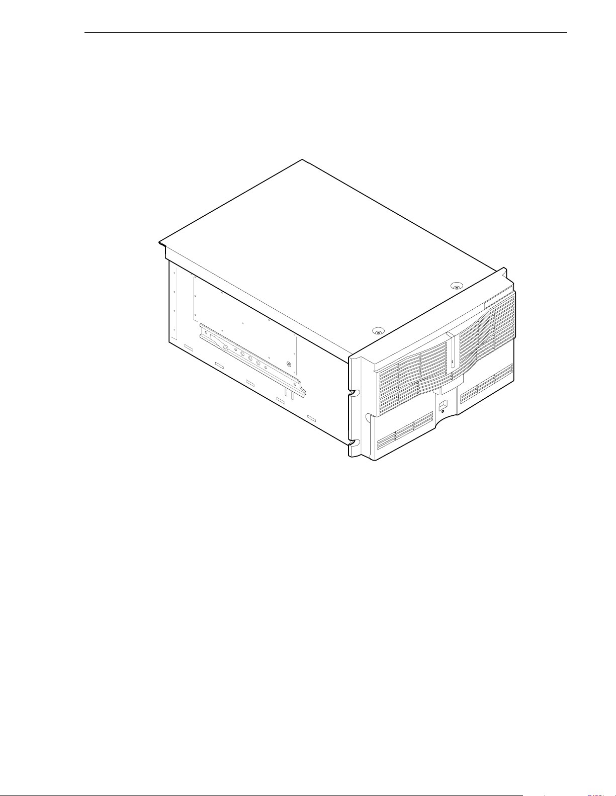
Product description
The Grass Vall ey P rofi le XP Medi a Plat form prov ides a high ban dwid th p latfo rm f or
the storage and manipulation of video and audio in professional applications
including spot insertion, program delay, store and forward, and multi-channel replay.
Product description
0625-2
The Profile XP Media Platfo rm
23 July 2004 Profile XP Service Manual 15
Page 16

Preface
Standard accessor ie s
The Profile XP Media Platform is shipped with the following standard accessories:
• Manuals Include:
- Installation Guide
- Profile XP System Guide
- Profile XP User Guide
- Profile XP Service Manual
- Profile XP Release Notes
• Software package which includes the Profile XP Software CD-ROM.
• Windows NT software package
• Keyboard and mouse
• I/O Panel and cables (provides LTC, RS-422 & GPI interfaces)
• Power cable
• Rack mounting slides
• Ethernet cable
• System rebuild CD-ROM
16 Profile XP Service Manual 23 July 2004
Page 17

Profile XP Media Platform features
Features common to all media platforms
• 16 (8 AES Pairs)/ 32 (16 AES pairs) channel audio - AES/EBU, embedded or
analog uncompressed audio, Dolby E and AC-3 compressed audio
• 600Mb / s System Bandwi dth
• Redundant power supply, NT disk, cooling fans for reliability
• External Fibre Channel RAID st orage (dua l controllers optional)
• Storage capability supported includes distributed storage for hundreds of channels
as well as centralized storage for up to 32 channels
• NetCentral™ provides remote error reporting and monitoring via SNMP
• High speed Fibre Channel networking up to 250Mb/s
• 100BaseT Ethernet networking up to 30Mb/s
• Remote control including:
- Remote Applications over Ethernet
Profile XP Media Pla tf orm fe at ures
- RS-42 2 con t ro l prot o c ol inc luding VDCP, O det i cs , BVW , or Pr of i l e prot o c o ls.
- GPI Trigger (8 I/O)
23 July 2004 Profile XP Service Manual 17
Page 18
Preface
PVS1000 features
• Up to 8 standard definition (SD) channels of broadcast-quality video
PVS1000 Series channel configurations by model
Model
Number
PVS1022 1 1 2 in/2 out
PVS1024 1 2 2 in/ 4 out
PVS1026 1 3 2 in/6 out
PVS 1042 2 1 4 in/2 out
PVS1044 2 2 4 in/4 out
PVS1062 3 1 6 in/2 out
PVS 1002 0 1 0 in/2 out
PVS 1004 0 2 0 in/4 out
PVS 1006 0 3 0 in/6 out
PVS1008 0 4 0 in/8 out
a.
MPEG Encoder and Decoder boards in PVS1000 series are Standard
Definition.
Numbe r of MP EG
Encoder Boards
Number of MPEG
a
Decoder Boards
Channel
Configuration
• MPEG-2 4: 2:2 @ Main Level from 4-50Mbs, long GOP
• SMPTE 259M, 270MHz Serial Digital I/O (Optional analog monitor with
timecode burn-in and text overlay)
• 525/60 or 625/50 operation: accepts NTSC, PAL
18 Profile XP Service Manual 23 July 2004
Page 19

PVS1100 features
• Up to 8 standard definition (SD) channels of broadcast-quality video
PVS1100 Series channel configurations by model
Profile XP Media Pla tf orm fe at ures
Model
Number
PVS1102 2 2 play/record
PVS1104 4 4 play/record
PVS1106 6 6 play/record
PVS1148 8 4 play/record
PVS1108 8 8 play/record
Number of video
codecs
Channel
Configuration
plus 4 play
• DVCPRO 25 video compression
• DVCPRO 50 video compression (req uires 50Mb/s option)
• MPEG-2 4:2:2 @ Main Level from 4 to 25Mb/s or 50Mb/s (requires 50Mb/s
option)
• MPEG-D10: I-frame to 50Mb/s CBG (requires 50Mb/s option)
• SDTI (optional): two channels, each can be configured as input or output.
DVCPRO 2 5 input at 1x, 2x, 4x; ou tput at 1x , 4x. DVCPRO 50 input at 1x, 2x;
output at 1x.
• SMPTE 259M, 270MHz Serial Digita l I/O (Opti onal analog monit o r with
timecode burn-in a nd text overlay)
• 525/60 or 625/50 operation: accepts NTSC, PAL
23 July 2004 Profile XP Service Manual 19
Page 20
Preface
PVS2000 features
• Up to 4 high definition (HD) channels of broadcast-quality video
PVS2000 Series channel configurations by model
Model
Number
PVS2012 1 1 1 in/2 out
PVS2013 1 2 1 in/ 3 out
PVS2004 0 2 0 in/4 out
PVS2022 2 2 2 in/2 out
PVS2212 1 HD, 1 SD 1 HD, 1 SD 2 in/2 out (SD)
a.
MPEG Encoder and Decoder boards in PVS2000 series are High Definition.
Number of MPEG
Encoder Boards
Number of MPEG
a
Decoder Boards
Channel
Configuration
1 in/2 out (HD)
• MPEG-2 4: 2:0 @ Main Level from 24-80Mbs, long GOP (for HD )
• SMPTE 292M, 1.485 Gbs Serial Digital I/O (includes downconverted SD SDI and
composite analog monitor with text overlay and timecode burn-in)
• 1080i and 720p line rates for HD, 50 and 59.94, accepts house black and tri-level
sync reference
20 Profile XP Service Manual 23 July 2004
Page 21

PVS3000 features
• Up to 7 channels of broadcast-quality video
• Standard and high definition channels can record and play concurrently
PVS3000 Series channel configurations by model
Profile XP Media Pla tf orm fe at ures
Model
Number
PVS 3004 0 1 1 2 SD out
PVS 3014 1 1 1 2 SD out
PVS3024 0 1 1 (4 Ch.) 2 SD in
PVS3034 1 1 1 (4 Ch.) 2 SD in
Number of HD
MPEG Encoder
Boards
Number of HD
MPEG Decoder
Boards
Number of SD
Video Processor
Boards
Channel
Configuration
2 HD out
1 HD in
2 HD out
2 SD out
2 HD out
2 SD out
1 HD in
2 HD out
• MPEG-2 4:2:0 @ Main Leve l from 24-80Mbs, lo ng GOP (for HD)
• MPEG-2 4:2:2 @ Main Level from 4 to 25Mb/s or 50Mb/s (requires 50Mb/s
option)
• SMPTE 292M, 1. 485 Gbs Seri al Digi tal I/O (i ncludes downconv erted SD SDI and
composite analog monitor with text overlay and timecode burn-in)
• SMPTE 259M, 270MHz Serial Digita l I/O (Opti onal analog monit o r with
timecode burn-in a nd text overlay)
• 1080i and 720p line rates for HD, 50 and 59.94, accepts house black and tri-level
sync reference
• DVCPRO 25 video compression
• DVCPRO 50 video compression (req uires 50Mb/s option)
• MPEG- D10: I-fra me at 30, 40, or 50Mb/s CBG (requires 50Mb/s option)
• 525/60 or 625/50 operation: accepts NTSC, PAL
•
23 July 2004 Profile XP Service Manual 21
Page 22

Preface
PVS3500 features
• Up to 7 channels of broadcast-quality video.
• HD decoders can play MPEG-2 4:2:0 SD and HD clips through either an SD or an
HD SDI output, down- or up-converted as required.
PVS3500 Series channel configurations by model
Model
Number
PVS3502 0 1 0 2 HD/SD out
PVS3504 0 2 0 4 HD/SD out
PVS3512 1 1 0 1 HD in
PVS3514 1 2 0 1 HD in
PVS3522 0 1 1 2 SD in
PVS3524 0 2 1 2 SD in
PVS3532 1 1 1 2 SD in
PVS3534 1 2 1 2 SD in
Number of HD
MPEG Encoder
Boards
Number of HD
MPEG Decoder
Boards
Number of SD
Video Processor
Boards
Channel
Configuration
2 HD/SD out
4HD/SD out
2 HD/SD out
4 HD/SD out
1 HD in
2 HD/SD out
1 HD in
4 HD/SD out
• MPEG-2 4: 2:0 @ Main Level from 24-80Mbs, long GOP (for HD )
• MPEG-2 4:2:2 @ Mai n Level from 4 to 25Mb/s or 50Mb/ s (requires 50Mb/s
option)
• SMPTE 292M, 1.485 Gbs Serial Digital I/O (includes downconverted SD SDI and
composite analog monitor with text overlay and timecode burn-in)
• SMPTE 259M, 270MHz Serial Digital I/O (Optional analog monitor with
timecode burn-in and text overlay)
• 1080i and 720p line rates for HD, 50 and 59.94, accepts house black and tri-level
sync reference
• DVCPRO 25 video compression
• DVCPRO 50 video compression (requires 50Mb/s option)
• MPEG-D10: I-frame a t 30, 40, or 50Mb/s CBG (requires 50Mb/s option)
• 525/60 or 625/50 operation: accepts NTSC, PAL
22 Profile XP Service Manual 23 July 2004
Page 23
Front panel con t ro ls and indicato rs
The Profile XP Media Platform front panel shown here includes the following
controls a nd i ndicators:
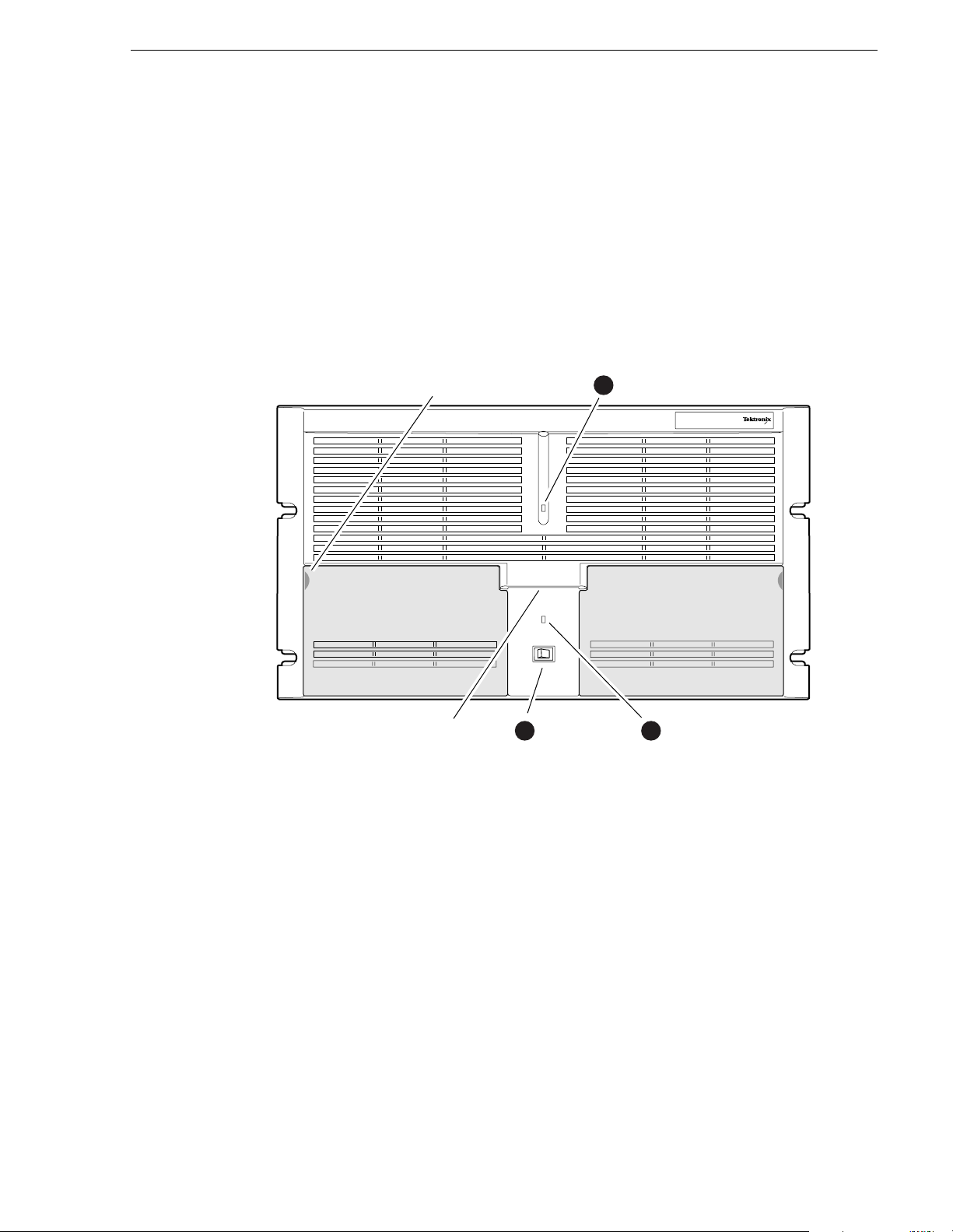
➊ Standby/On LED - indicates the standby switch is in the on position and that
secondary voltages are present in the chassis.
➋ Standby/On Switch - provides system On/Off control.
➌ System Fault LED - indicates a system fault somewhere in the Profile XP system.
This LED is under control of the NetCentral system and goes off when NetCentral
receives notice from the system that the cause of the fault is cleared.
Front panel controls and indicators
Pull here to
open (each side)
Accessory
Door
Standby/On
2
Switch
Profile XP Media Platform front panel
1
Standby/On LED
Accessory
Door
System
3Chassis Pull
Fault LED
0624-5
The Profile XP front panel features two accessory doors that provide access to several
application subsystem storage devices. A system with standard equipment is shown
on page 24, while a system equipped with the redundant storage option is shown on
page 25.
23 July 2004 Profile XP Service Manual 23
Page 24
Preface
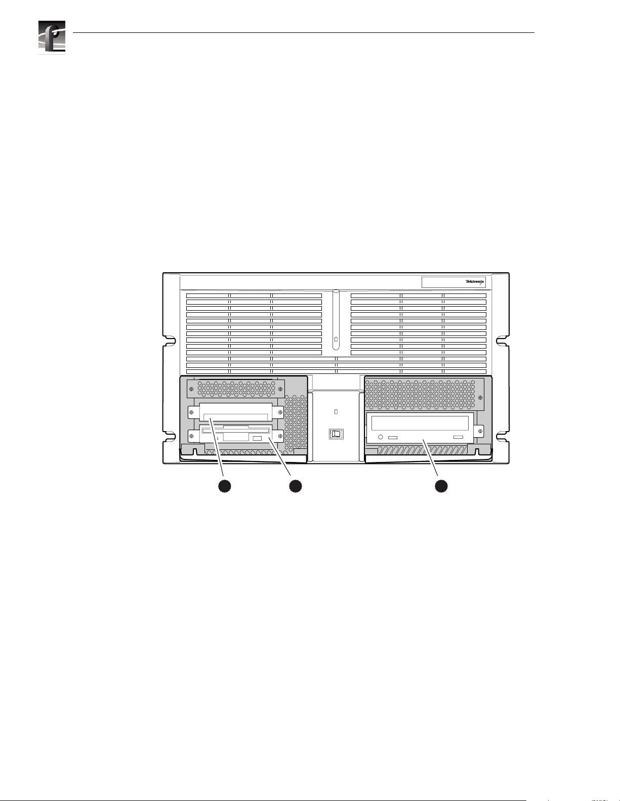
The storage devices in the standard system include:
➊ System Drive - contains Windows N T operating system and Profile XP software
and applications.
➌ 1.44MB Floppy Disk Drive - for installing operating system and Profile XP system
software upgrades.
➍ CD-ROM Drive - for installing operating system and Profile XP system software
upgrades.
NOTE: The snap-in hinges in the front panel accessory doors allow you to easily
pop the door back into place should it be accidentally knocked from its hinges.
0624-4
System
1
Disk Drive
Profile XP Media Platform with accessory doors open
Floppy
2
Disk Drive
CD-ROM
3
Drive
24 Profile XP Service Manual 23 July 2004
Page 25
Front panel controls and indicators
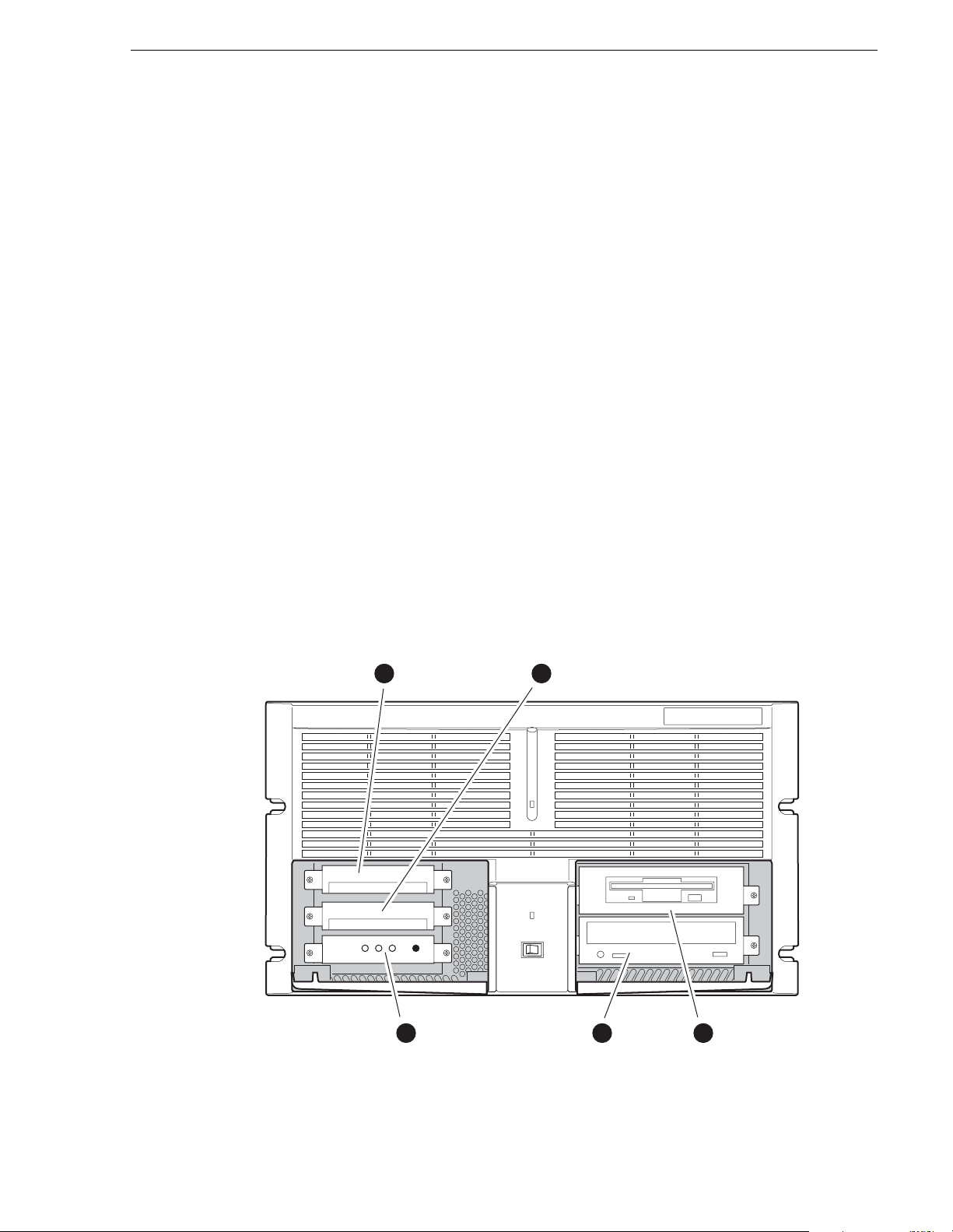
The storage devices in the system with the redundant system disk option include:
➊ Primary System Drive - contains Win dows NT operating system and Profile XP
software and applications.
➋ Mirror System Di sk - mirrors primary system disk and provides automatic fail-over
in the event primary system disk fails.
➌ Drive Mirroring Controller and Indicator Panel - The Primary and Mirror LEDs
monitor the status of the channels as follows:
- Green - Drive installed on the current channel
- Red - Drive not installed or channel marked as bad
- Orange - Drive activity
The Status LED indicates the operating mode of the mirroring system:
- Green - Drives are in Mirror mode
- Red - Drives in Single mode
The Buzzer Off switch can be used to silence the buzzer, which sounds under the
following conditions:
- Short beep during power on indicates successful boot-up
- Second beep indicates the mirroring system is running in single mode
- Continuous or intermittent beep indicates a drive failure
➍ CD-ROM Drive - for installing operating system and Profile XP system software
upgrades.
➎ 120MB Superdrive or 1.44MB Floppy Drive - the Super-Drive accepts 1.44MB
floppy dis ks and 120MB disks.
DupliDisk
Primary System
1
Disk Drive
Primary
Mirror Status Buzzer
3
DupliDisk
Indicator Panel
Mirrored System
2
Disk Drive
4
CD-ROM
Drive
Superdrive or
5
Floppy Drive
0625-18
Profile XP with redundant system disk option
23 July 2004 Profile XP Service Manual 25
Page 26
Preface
Profile XP system ove rview
The Profile XP Media Platform system is an extension to a standard PCI bus based
Windows NT Computer. This standard computer base is enhanced to add
functionality and performance necessary to deliver an industrial grade, broadcast
quality, disk-based media platform. This section discusses the major architectural
blocks, what they do, and how they interconnect. A more detailed overview of the
system is available in Appendix B, Theory of operat i on.
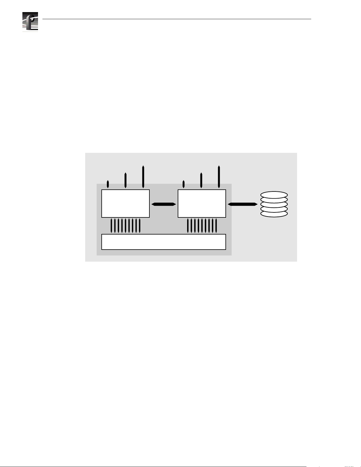
The Profile XP Media Platform consists of two major subsystems, the Application
Subsystem and the Real Time Subsystem, and the platform resources needed for them
to functi on. Thes e are sh own in the dark er tinte d area of the hig h-level block di agram .
A third major subsystem, the Media Storage Subsystem, is external to the media
platform.
Configuration
Control
User I/F
Application
Subsystem
Platform resources
The platform resources provide the infrastructure necessary to operate, interconnect,
and integrate all the components of the Application and Real Time Subsystems. The
platform resources include the multi-slot PCI bus, the video & audio crosspoint fabric,
the power supply, and system cooling.
Applications subsystem
Video I/O
IPM
Channel
Subsystem
Platform Resources
High-level Block Diagram
Media Networking
Audio I/O
Real Time
Media Storage
Subsystem
Fibre
Channel
0625-4
The Applications Subsystem is a Windows NT computer subsystem in a standard
NLX single board computer form factor. The Applications Subsystem provides a
platform for runni ng Wi ndows b ased appli catio ns tha t co nfigu re an d contr ol t he Real
Time Subsystem both locally and remotely.
26 Profile XP Service Manual 23 July 2004
Page 27

Real Time subsystem
The Real Time Subsystem contains a real time processor and peripheral devices and
runs the VXWorks operating system.The Real Time Subsystem manages all the
hardware involved in controlling the flow of video, audio, and timecode in and out of
the system. This includes video I/O boards, audio I/O boards, video compression
boards, an d networking and storage. The Real Time Subsy s tem is controlled by
applications running on the Applications S ubsystem using Inter-Processor Messaging
channels (IPM). It is responsible for the execution of events on the play time line.
Media storage subsystem
NOTE: If your P r ofile XP Medi a Platform is part of an Open SAN, refer to th e
Open SAN Installation Guide for information about media storage.
The Storage Subsystem is where the video, audio, timecode and other media related
data is stored. This storage system is made up of one or more external RAID level 3
storage chassis containing Fibre Channel disks. The Profile XP Real Time Subsystem
controls re ad /w rit e dis k op e rati ons by se n din g SCSI pr oto col com man ds o ver one or
more Fibre Channel links.
Profile XP system overview
23 July 2004 Profile XP Service Manual 27
Page 28

Preface
28 Profile XP Service Manual 23 July 2004
Page 29

Chapter
1
Characterizing the problem
This is your first step in diagnosing the problem you are having with your Profile XP
Media Platform. The information presented here and the questions asked will enable
you to:
• Determine the nature of the problem
• Direct you to the area of the manual that deals more specifically with the problem
you are experiencing
You will also find brief discussions of the diagnostic aids available on the media
platform. In cases where the error message carries with it the remedy to the cause, you
will not need to go beyond this chapter.
Localizing the problem
In determining the nature of the problem, there are four questions that will in most
cases help you localize the problem to one of the three major subsystems.
What was the media platform doing when the problem occurred?
Another wa y to ask this would be, “What were you doing w ith the media platform
when the problem occurred?” or “How were you using the media platform when the
problem occurred?” This can include “When did the problem occur?”
• Does the problem occur at start-up?
Any failure before the desktop ap pears is mos t likely a Windows NT b oot proble m. If
you are experiencing boot problems, refer to Chapter 2, Troubleshooting Windows NT
boot proble ms, which covers the potential problems you can encounter during the
WindowsN T boot sequence.
• Can you record and play video, audio, and timecode?
Record and play problems can have a number of causes. The most frequent problems
result from a change in configuration, or cables being accidentally disconnected or
misconnected. R efer to Chapt er 3, Troubleshooting video problems, Chapter 4,
Troubleshooting audio problems, or Chapter 5, Troubles hooting tim ecode probl ems
for help determining those problems.
If an automatic controller is used to operate the media platform, refer to Chapter 9,
Troubleshooting channel control problems for dealing with possible problems cau sed
by controller interface problems.
• Is there a problem with the video network?
If you are having network problems such as an inability to access other Profile
systems on the network see Chapter 7, Troubleshooting video network problems,
which deals with possible problems in the fibre channel or ethernet video network
systems.
23 July 2004 Profile XP Service Manual 29
Page 30

Chapter 1 Characterizing the problem
What has changed?
If the media platform has been working, but has suddenly developed a problem, think
of what has changed in the system.
• Have you changed resources for any of the channels?
• Have you installed any software?
• Have you installed or removed a board?
If reversing the changes restores the system, perhaps there is a problem with the
software or hardware that was installed or removed.
What error indications wer e repo rted by the NetCentral system?
The NetCentral system monitors the operational status of the media platform, keeping
track of a number of operating parameters and the health of the circuit boards. Many
of the messages displayed by the NetCentral system contain the remedy for a problem
along with the notification. NetCentral also generates log files that you can use to help
determine where and when faults have occurred. Refer to “Viewing logs” on
page 134.
What attempts have you made to remedy the problem?
Keep track of efforts you make to remedy your problem. In the event that you need to
contact Grass Valley Support, this information can greatly assist the person working
with you to isolate and correct the problem.
Readily diagnosed problems
Many problems are easily diagnosed because they are primarily hardware faults that
are indicated by messages at boot time or because they generate a NetCentral Alarm
or an Attention message.
• Power-supply fa ilure
• Fan failure
• Temperature (fans/filter/overload)
• Applic a ti on s pr oc es s or boot failur e
Any of the plug-in circuit boards in the media platform will generate a NetCentral
Alarm message if the board fails. This message states the name of the board and its
slot location in the Profile XP media platform, and recommends that you replace the
board.
30 Profile XP Service Manual 23 July 2004
Page 31

Diagnostic tools
Several diagnostic tools are available to you for determining the nature and source of
a problem. They are listed here with brief explanations of their uses, and they are
discussed in more detail in Appendix A, Diagnostic Tools.
NetCentral — Monitors the state of the Profile XP media platform, and alerts you to
component failures and maintenance needs. This system uses SNMP managers and
agents to monitor one Profile XP media platform locally or, if you are using optional
full-featured NetCentral, many Profile XP systems from a remote location. The
system constantly monitors the status of the Profile XP media platform and generates
Attention (warning) messages when hardware failures are imminent or when
operating conditions are degrading, and generates Alarm (critical) messages when
hardware failures occur or when the operating environment exceeds safe parameters.
Profile XP Diagnostics — A diagnostic suite that checks the functionality of the
boards in the Profile XP Media Platform.
Windows NT diagnostic tools — Provid ed by Mic ros of t for us e in tr oub l esho ot in g
problems with Windows NT.
POST — Power-On Self-Test. Basic tests to assess the initial health of the system as
it boots.
Diagnostic tools
23 July 2004 Profile XP Service Manual 31
Page 32

Chapter 1 Characterizing the problem
32 Profile XP Service Manual 23 July 2004
Page 33

Chapter
2
Troubleshooting Windows NT boot problems
This chapter deals with problems that occur between setting the switch to “on” and
the appearance of the desktop on the monitor screen. During this period, the power-on
self-test runs and Windows NT boots.
Pre-boot problems
The pre-boot sequence of events occurs when you first turn on the computer before
Windows NT loads and begins to run. The problems that occur during pre-boot are
primarily hardware problems. These problems are typically in the Applications
Processor board or in one of the peripherals attached to it: the display, the keyboard,
the mouse, the system drive, or the diskette drive. When these events are complete,
the computer is ready t o begin loa ding Windows NT.
The following table lists some possible p roblem symptoms that you might see as error
messages that appear during the Power-On Self-Test (POST).
Symptom Possible Cause Solution
Error message indicating failure
in a hard disk drive.
Error message indicating failure
in diskette drive
Error message indicating
keyboard problem.
Error message indicating
inability to find boot device or
operating system.
Error message in dicating CMOS
battery low or dead.
Error message indicating
memory problem.
Error message indicating timer
or clock problems.
No display Component failure in
Hard disk drive failure Try replacing the hard disk
drive.
Connecting cable failure Check the connecting cable,
replace if necessary.
Diskette drive failure Try replacing the diskette drive.
Connecting cable failure Check the connecting cable,
replace if necessary.
Keyboard unplugged Plug in keyboard
Keyboard or connecting cable
defective
Hard disk drive failure Try replacing the hard disk
Connecting cable failure Check the connecting cable,
Battery low or dead Replace Applications Processor
Defective memory. Replace Applications Processor
Component failure in
Applications Processor board
Applications Processor board
Monitor or cable failure
Replace keyboard
drive.
replace if necessary.
board.
board.
Replace Applications Processor
board.
Replace Applications Processor
board.
23 July 2004 Profile XP Service Manual 33
Page 34

Chapter 2 Troubleshoo ting Windows NT boot probl em s
These are messages you might see reported by NetCentral at a remote monitoring
station that relate to system startup for a Profile XP system. No entry in the Possible
Cause column means that the cause is implicit in the problem statement, that knowing
the cause is unimportant to the solution, or in the case of status messages, there is no
cause.
Problem Possible Cause Corrective Action
Flash ROM image download and
execution error detected on the
boardtype board in slot Jn. The Pro file
XP system might operate incorrectly.
Power-On-Self -Test failure dete cted for
the boardtype board in slot Jn. The
Profile XP system might operate
incorrectly.
Mismatching software version detected
on the boardtype board in slot Jn. The
Profile XP system might operate
incorrectly.
Hardware failure on the
board.
Incorrect or incomplete
installation of Profile
XP System Software.
• Restart the Profile XP
system.
• Reload the system
software.
• Contact Support.
Do one or more of the following:
• Restart the Profile XP
system.
• Reload the system
software.
• Replace th e board.
• Contact Support.
Reload the system software if the
Profile XP system operates
incorrectly.
Booting Windows NT
This is the sequence that the computer follows when loading Windows NT.
1. Load NTLDR into memory and run it.
2. NTLDR reads co n te n t s o f Boot.ini. On the screen it displays the boot loader menu,
a menu that allows the user to select which operating system to load.
3. NTLDR loads Windows NT, or Windows NT VGA-mode if selected by the user.
4. NTLDR executes NTDETECT.COM.
On the screen, NTDETECT displays “NTDETEC T V1. 0 Checki n g Hard ware…”
5. Ready to load and initialize Windows NT.
Display:OS Loader V4.0
Press spacebar now to invoke Hardware Profile/Last Known Good menu.
6. Initialize Windows NT.
The screen turns blue with white lettering.
7. Begin loading Windows NT. The boot process is complete when the desktop
appears following a user log on or autologon.
Invoking
LastKnownGood
As its name implies, LastKnownGood is a copy of the configuration from the last
successful syste m boot-up. Invoking LastKnownGood allows you to overcome
configuration related boot problems. It is used to undo any configuration changes that
did not have the intended effect, such as those caused by adding a new driver to the
system, or those caused by user-modified registry values. However, LastKnownGood
does not repair corrupted or missing drivers or files.
34 Profile XP Service Manual 23 July 2004
Page 35

Windows NT boot problems
LastKnownGood is loaded in when the user presses the space bar at the prompt before
Windows NT begins to load.
It is important to remember that when you invoke LastKnownGood, any system
configuration changes made since the last successful start up are discarded. And once
you successfully log on, the configuration used becomes LastKnownGood
Windows NT bo ot problems
Possible problems that occur during the Windows NT boot sequence are listed in the
following table. These problems can be repaired using the emergency repair process
described later in this chapter.
Problem Probable cause
Windows boots without displaying Boot Loader Menu
or
Problem in Windows NT Path
New boot loader operating system menu item appears If the path for the default operating system in the boot
This will occur if Boot.ini is missing. If Boot.ini is
missing NTLDR will boot from the \winnt directory by
default. If this is the correct directory, Windows NT
boots automatically. If not, the following message
appears:
Windows NT could not start because the following
file is missing or corrupt:
\winnt root\system32\ntoskrnl.exe
Please reinstall a copy of the above file.
loader section of the boot.ini file does not match any
paths in the operating system portion of the file a new
entry, “NT (default)” will be added to the operating
system portion of the file. This new entry will be
highlighted and used to boot NT if user does not make
a selection.
The following message is displayed:
OS Loader V4.0
Windows NT could not start because of a computer disk
hardware configuration. Could not read from the selected
boot disk. Check boot path and disk hardware. Please check
the Windows NT (TM) documentation about hardware disk
configuration and your hardware reference manuals for
additional information.
The following error message is displayed:
Boot: Couldn’t find NTLDR
Please insert another disk
The following error message is displayed:
NTDETECT V1.0 Checking Hardware…
NTDETECT failed
The following error message is displayed:
Windows NT could not start because the following file is
missing or corrupt:
\winnt root\system32\ntoskrnl.exe
Please re-install a copy of the above file.
The following error message is displayed:
I/O Error accessing boot sector file
multi (0) disk (0) rdisk (0) partition (1):\bootsect.dos
Invalid device (Name, for instance) in Windows NT
path in boot.ini.
NTLDR file is corrupt or missing
Ntdetect.com file is corrupt or missing
Ntoskrnl.exe file is corrupt or missing
Bootsect.dos file is corrupt or missing
23 July 2004 Profile XP Service Manual 35
Page 36

Chapter 2 Troubleshoo ting Windows NT boot probl em s
Using the emergency repair process
The emergency repair data located in c:\winnt\repair and on the Emergency Repair
Disk (ERD) is used to restore a Windows NT workstation back to the state of the last
repair update. It is used to search for missin g or corrupt Windows NT files and to
restore the registry files, including SAM database, security information, disk
configuration, software registry entries, and other information.
Use of the Emergency Repair Disk (ERD) is called for when Windows NT Fails to
function correctly and invoking the LastKnownGood configuration does not solve the
problem. Some points to remember when using the ERD:
• The ERD is computer specific. An ERD created on one computer will not work on
another unless the computers are identical and the software is installed in the same
locations.
• If you replace the SAM database, you must remember the Administrator password
used when the ERD was updat ed.
• Using the ERD returns the system to the state it was in at the time of the last update
to the Emerge ncy Repair di rectory o r disk.
Follow this procedure to use the ERD:
1. Locate the Windows NT installation CD-ROM. You need the installation
CD-ROM in case any system files are bad or missing. Also locate the installation
media for any Service Packs or Y2K fix installed on the computer.
NOTE: If you repair System files, the emergency repair process DELETES all
Service Packs and the Y2K fix; you must re-install them at the end of the process.
2. Insert the Windows NT Setup disk 1 and restart the computer. The repair process
is a part of Windows NT Setup.
3. Insert Disk 2 when prompted , and type “
R” to select repair from the Setup Menu
that appears (do not select new or update). The following menu appears:
[X] Inspect registry files
[X] Inspect start-up environment
[X] Verify Windows NT system files.
[X] Inspect boot sector.
Continue (perform selected tasks)
4. Leave all choices selected, choose Continue, and press
5. When prompted, inse rt Windows NT Workstati on Setup Di sk #3 and press
6. When prompted to scan for mass storage devices press “
7. In the next screen press “
8. Select “Other” and press
S” again, this time to specify the CD ROM Drive.
Enter.
Enter.
Enter.
S” to skip.
9. Insert the CDROM Driver floppy disk when prompted, then press
10.Select “FIT” and press
Enter to continue.
Enter.
11.When prompted, a ga in insert Windows NT Workstation Se t up Disk #3 an d press
Enter to continue.
36 Profile XP Service Manual 23 July 2004
Page 37

Rebuilding the syst em dri ve
12.Ins ert the ERD when pr ompted. If you do not have an ER D, the repair pro cess uses
the repair data it finds under c:\winnt\system32\repair.
13.Conf irm that you want your hard disk(s) examined for co rruption by pressing
Enter.
14.The r egistry repa i r choices appear if you l eft “inspect regist ry files” selected.
[X] SYSTEM (System Configuration)
[X] SOFTWARE (Software Information)
[ ] DEFAULT (Default User Profile)
[ ] NTUSER.DAT (New User Profile)
[ ] SECURITY (Security Policy and SAM (User Accounts Database)
Continue (perform selected tasks)
Select the keys you want to restore by entering X between brackets, then highlight
Continue and press
choices because in most cases they will correct problems that require emergency
repair.
Enter. SYSTEM and SOFTWARE are the recommended
15.Press
16.Re-install the Windows NT service pack(s) and Y2K fix that were in use before
Enter to restart the computer.
you performed the emergency repair process.
Rebuilding the system drive
On occasion, the system drive might become corrupted in such a way that installation
with the ERD is impossible, or the system drive might fail and the replacement drive
has nothing on it. In such a case, you can rebuild the system drive using the process
described in “Installing a new system disk or restoring a corrupt system disk” on
page 91.
23 July 2004 Profile XP Service Manual 37
Page 38

Chapter 2 Troubleshoo ting Windows NT boot probl em s
Re-installing and configuring drivers
In the event that the display, Ethernet, or RS -422 drivers are co rrupted or the s ettings
lost, here is the information you need for re-installing the drivers and making settings
that return the Profile XP media platform to its factory default conditions. Drivers for
the Ethernet adapter, the VGA adapter, and the RS-422 board are located in
c:\profile\Drivers. When a dialog box requests a location for a file normally found on
the CD-ROM, start the path name with c:\profile\Drivers\…
In the table below, note that there are two sets of display drivers and ethernet adapters,
each set associated with a system processor board rear panel. Select the drivers
associated with the rear panel that matches the system processor in your media
platform. Note also that the one RS-422 driver is used with either system processor
board.
Hardware Driver Location Factory settings
VGA adapter for
use with this
system process or.
Ethernet adapter
for use with this
system process or.
RS-422 board for
use with all
system
processors.
VGA adapter for
use with this
system process or.
Ethernet adapter
for use with this
system process or.
ATI Rage PRO c:\profile\Drivers\ATI_RAGE Desktop Area: 1024 X 768
Intel EtherExpress
PRO Adapter 82558
Comtrol RocketPort c:\profile\Drivers\rocket Com Port Range:
Intel 810 Graphics
Controller Hub
Intel (R) GD82559ER
Fast Ethernet Adapter
c:\profile\Drivers\Intel_PRO Memory Address:
c:\profile\Drivers\Intel_810 Desktop Area: 1024 X 768
c:\profile\Drivers\Intel_GD82559ER Speed and Duplex set to
Refresh Rate: 70 Hz
Color Palate: 24 bit,
16,777,216 Colors
0xFC000000
I/O Address: 0x1000
Interrupt: 9
Starting COM Port: COM3
Scan Rate (ms): 1
Refresh Rate: 70 Hz
Color Palate: 24 bit,
16,777,216 Colors
Auto Select.
38 Profile XP Service Manual 23 July 2004
Page 39

Chapter
3
Troubleshooting video problems
If your video problem is a resul t of equipment failure, your first indication might be
a message in the NetCentral system. The tables of NetCentral messages list the
Warning and Alarm messages you might see, with some possible causes and
solutions.
When you are troubleshooting video problems and you have determined that the
problem is hardware related, remember that you are trying isolate the fault to a
field-replaceable unit. There are several field-replaceable units that could cause video
problems:
• An SDI or HD SDI board, a Video Monitor board, or the SDTI board
• the Motherboard
• the MP EG-2 Encoder or Decoder board (P VS1000 or 2000), or the V ideo
Processor board (PVS 1100)
In general, yo u c an ve rify or rule out hard wa re pro bl ems by using the Profile XP
diagnostics described in Appendi x A, Diagnostic Tools. If the diagnostics indicate
that a board is defective, replace that board.
In many cases an improper configuration setting or other change in the system setup
can result in video problems. Search through the problems listed in “Correcting
common setup problems” and “Correcting common video problems” later in this
chapter.
The System Guide referred to in the tables in this chapter is the Profile XP System
Guide.
Checking NetCe ntral messages
These are Warning and Alarm messages you might see from the NetCentral system.
The tables present the messages that appear as a result of some fault condition in th e
SDI board, MPEG-2 Decoder and Encoder boards, or Video Proc essor board.
SDI prob lems
Problem Possible Causes Corrective Action
Video is not present at SDI input N.Cable disconnected or damaged. Reconnect cable, after repairs if
Signal source interrupted. Check that signal is available
SDI digital signal processor N
has failed.
Defective board. Do one or more of the following:
necessary.
from source.
• Run Profile XP
diagnostics to verify that
the board has failed.
• Replace the board.
• If the problem persists,
contact Support.
23 July 2004 Profile XP Service Manual 39
Page 40

Chapter 3 Troubleshoo ting v ide o problems
SDTI prob lem s
Problem Possible Causes Corrective Action
The SDTI board in slot J-N
failed to initialize.
The SDTI channel using
connector N has failed. The
record or playback operation on
this channel will abort. Other
SDTI channels will continue to
operate.
Unable to detect an SDTI input
signal on connector N. No video
will be recorded.
The SDTI input signal on
connector N is the wrong data
format. Recording will abort on
the channel associated with this
input.
A valid SDTI input signal is
detected on connector N.
Recording will continue on the
channel associated with this
input.
One or more ECC checksum
errors were detected while
recording the input signal on
connector N. Media recording
will continue.
This could be due to a
communication failure between
the SDTI board realtime and I/O
processors, or a hardware fault.
This could be due to a
communication failure between
the SDTI board realtime and I/O
processors, or a hardware fault.
Restart the Profile XP system,
and run Profile diagnostics.
Restart the Profile XP system,
and run Profile diagnostics.
Check the signal source, cable
connection, and input signal
frame rate.
Check that the record channel
configuration matches the input
signal data format.
Confirm the quality of the
recorded media, then re-record
if necessary.
40 Profile XP Service Manual 23 July 2004
Page 41

Video playback (decode) problems
Problem Possible Causes Corrective Action
Decoder# X failed to initialize
on slot J-N.
The decoder driver on slot J-N is
not able to establish
inter-processor communicati ons
at startup.
Could not allocate resources for
the task on the Real Time
System.
The decoder on slot J-N failed to
initialize because it was
deprived of a system wide
resource (such as a DMA
channel). Playback tasks
associated with this board will
fail.
The decoder on slot J-N
encountered an error while
accessing the storage system.
Playback tasks will fail, produce
frozen or black video.
The decoder on slot J-N can now
access the storage system.
The decoder on slot J-N is
unable to decode due to
insufficient memory. Playback
tasks may fail, produce frozen,
stuttered, or black video.
The decoder in slot J-N is now
able to decode.
Defective board, or problem
with internal software. Check
system status.
Video playback (decode) problem s
Do one or more of the following:
• Restart the Profile XP
system.
• Replace the board.
• Contact Support.
23 July 2004 Profile XP Service Manual 41
Page 42

Chapter 3 Troubleshoo ting v ide o problems
Video record (en c od er) pro bl em s
Problem Possible Causes Corrective Action
Encoder# %d failed to initialize
on slot J-N.
Encoder# %d failed to initialize
on slot J-N.
The video system is unable to
establish inter-p roc e ss or
communications for the encoder
on slot J-N. Media recording
tasks may fail.
The encoder on slot J-N failed to
initialize because it was
deprived of a system wide
resource (such as a DMA
channel).
Interprocessor communication
error between the encoder's
media driver on the
Real-Time-System board and
the driver on Encoder board.
Recording tasks may fail.
The storage system is
responding too slowly to the
encoder media driver. Video
may be dropped shortly. Verify
that the storage system is not
exceeding bandwidth limits.
The storage system is
responding too slowly to the
encoder media driver. Video
may be dropped shortly. Verify
that the storage system is not
exceeding bandwidth limits.
The storage system has
responded too slowly to the
encoder media driver. Video has
been dropped and black
frame(s) have been recorded.
The storage system has
responded too slowly to the
encoder media driver. Video has
been dropped and black
frame(s) have been recorded.
The Profile has detected
frequent CRC errors (more than
10 times an hour) on SDI input
on slot J-N. This could result in
bad recording.
Defective board, or problem
with internal software. Check
system status.
Do one or more of the following:
• Restart the Profile XP
system.
• Replace the board.
• Contact Support.
Check the SDI video input(s) for
bad signal sources or bad
cabling
42 Profile XP Service Manual 23 July 2004
Page 43

Correcting commo n set up problems
Correcting common setup problems
This troubleshooting aid provides corrective action for some common record/play
problems. Search the table for the problem you are experiencing, then try the
corrective action. Some problems have more than one corrective action.
Problem Possible Causes Corrective Action
Application fails to select a
channel or channels when it is
started.
The recorded clip contains
colorbar.
The recorded clip contains black
or freeze frame.
The channel output is black in
E t o E, but playback is fine.
Channel output is always black. The output you’re monitoring is
Freeze frames or black frames
during playback.
Resource conflict because a
resource needed by the channel
is already in use.
The colorbar generator is
selected as the channel input.
Loss of input signal. Verify that you have a valid
Loss of input signal. Verify that you have a valid
not assigned to the channel.
The number of record and play
channels operating
simultaneously exceeds the
system storage bandwidth.
Check for resources that may be
assigned to more than one
channel and correct the problem
Refer to “Using the Warning
symbol to find shared
resources” in the P rofile XP
System Guide. Also, make s u re
the Channel Configuration
dialog box is closed before
running the application or
selecting channels.
Select the desired video input as
the channel source. Refer to
“Selecting video quality and
crosspoints” in the Profile XP
System Guide.
input signal. Refer to “Viewing
video input status” in the
Profile XP System Guide.
input signal. Refer to “Viewing
video input status” in the
Profile XP System Guide.
Determine the video output
assigned to the channel by
referring to “Selecting video
quality and crosspoints” in the
Profile XP System Guide, then
verify cable connections.
Reduce the number of channels
operating at the same time, or
select a lower video quality
preset for the record. Refer to
“Guidelines for selecting Video
Quality Presets” in the
Profile XP System Guide.
23 July 2004 Profile XP Service Manual 43
Page 44

Chapter 3 Troubleshoo ting v ide o problems
Correcting common video problems
This troubleshooting aid provides corrective action for some common video
problems. Search the table for the problem you are experiencing, then try the
corrective action. Some problems have more than one corrective action.
Problem Possible Causes Corrective Action
Video output distortion in
playback and E to E.
Continuous horizontal picture
shift in Record mode (or E to E).
Sometimes intermittent
depending on the input signal
selected.
Playout timing is 16 lines
delayed
Vertical shift when switching
between video input and
playout.
Compression artifacts are
present in the output.
Wrong video standard. Verify system video standard is
Input frame sync set to “pass”
when incoming signal is
asynchronous.
Playout timing set to E to E
timed output.
Playout timing set to
Zero-Timed output.
Video quality setting is too low
for your program material.
configured correctly. Refer to
“Changing the system video
standard” in the Profile XP
System Guide.
Set frame sync to “Auto-time”.
Refer to “Options for timing
asynchronous feeds” in the
Profile XP System Guide.
Change playout timing to
“Zero-Timed” output. Refer to
“Adjusting playout timing to
match zero time” in the
Profile XP System Guide.
Change playout timing to
“E to E-Timed” output. Refer to
“Adjusting playout timing to
match E to E timing” in the
Profile XP System Guide.
Select higher video quality
preset (refer to “Guidelines for
selecting Video Quality Presets”
in the Profile XP System Guide,
or define your own video quality
preset. Refer to “Defining and
selecting a custom video quality
preset” in the Profile XP System
Guide.
44 Profile XP Service Manual 23 July 2004
Page 45

Chapter
4
Troubleshooting audio problems
If your audio problem is a resul t of equipment failure, your first indication might be
a message in the NetCentral system. The tables of NetCentral messages list the
Warning and Alarm messages you might see, with some possible causes and
solutions.
When you are troubleshooting audio problems and you have determined that the
problem is hardware related, remember that you are trying isolate the fault to a
field-replaceable unit. There are four field-replaceable units that could cause video
problems:
• An SDI board (if you are working with embedded audio)
• the Motherboard
• An Audio board
• An audio interface (a PAC216 Audio Chassis or BNC/XLR216 breakout box)
In general, yo u c an ve rify or rule out hard wa re pro bl ems by using the Profile XP
diagnostics described in Appendi x A, Diagnostic Tools. If the diagnostics indicate
that a board is defective, replace that board.
In many cases an improper configuration setting or other change in the system setup
can result in audio problems. Search through the problems listed in “Correcting
common audio problems” later in this chapter.
The System Guide referred to in the tables in this chapter is the Profile XP System
Guide.
Checking NetCe ntral messages
These are Warning and Alarm messages you might see from the NetCentral system.
Audio probl e m s related to SDI board
Problem Possible Causes Corrective Action
The Profile has detected frequent
audio sync errors (more than 10 times
an hour) while extracting embedded
audio from its SDI input on slot N.
This could result in recording where
the audio and video are out of sync.
The Profile has detected frequent
errors (more than 10 times an hour)
while extracting embedded audio
from an SDI input on slot J-N.
Bad signal from source. • Check the SDI video
input(s) for bad signal
sources or cabling.
• Try another source or
a known good source.
• Replace the board.
• Contact Support.
23 July 2004 Profile XP Service Manual 45
Page 46

Chapter 4 Troubleshoo ting audio problems
Audio problems rel at ed t o A udio board
Problem Possible Causes Corrective Action
Internal memory problems in the
Digital Signal Processor during
play.
The audio system was unable to
extract embedded during an EE
or record mode. This indicates a
loss in audio and a possible loss
in video.
Audio is lost due to a loss in
connectivity between
Receive-Port N on the Audio
board and the crosspoint fabric.
The recording and playing of
audio will be disrupted due to a
bad audio-clock average sample
count.
The Digital Signal Processor is
producing poor audio.
Bad recording, or bad E-E audio
(fifo overflow).
Disrupted play/record of audio
with AES I/O.
The DSP's internal memory
buffers have overflowed during
play mode.
Disrupted audio clock.
Audio sample clock reference
incorrectly selected.
The DSP hardware has failed to
wait for a new mode because its
command queue is full and is not
producing good audio.
SDI input error.
Loss of input signal due to no
signal or poor signal from source.
Loss of input signal due to cable
disconnect.
Do one or more of the following:
• Restart the Profile XP
system.
• Replace the board.
• If the problem persists
contact Support.
Do one or more of the following:
• Check for loss of input
signal.
• Replace the board
• Restart the Profile XP
system.
• If the problem persists,
contact Support.
Check for configuration
problems. See the table under
“Correcting common audio
problems” on page 48..
Use system reference as audio
clock reference for synchronous
video signals.
Do one or more of the following:
• Restart the Profile XP
system.
• Replace the board.
• If the problem persists
contact Support.
Check presence and quality of
input signal from source.
Check all cabling into breakout
box and between breakout box
and Audio board.
46 Profile XP Service Manual 23 July 2004
Page 47

Audio problems related to Audio board
Problem Possible Causes Corrective Action
The Profile is unable to connect
to the PAC216 serial I/O interrupt
through the Audio board in slot
J-N. Communications with the
audio option will fail.
The Profile was unable to create a
serial port for the PAC216
connected to slot J-N.
Communications with the audio
option will fail.
The Profile was unable to open
the serial port for the PAC216
connected to slot J-N.
Communications with the audio
option will fail.
The Profile audio system
received an invalid
inter-processor communication
message during startup or
configuration. The audio system
may not operate as expected.
The audio system software
encountered an inter-processor
messaging write error during
startup or configuration.
The PAC216 connected to the
Audio board in slot J-N failed to
reset. Audio may be lost, or
analog audio could be at the
wrong level.
There was a temporary loss of
contact between the Profile and
the PAC216, XLR216, or
BNC216 connected to slot J-N.
The Profile has reset to the last
known good audio state. This
may result in an audio glitch.
The Profile has lost contact with
the external audio interface
(PAC216, XLR216, or BNC216)
connected to in slot J-N. Audio
will be lost on all the channels
using audio resources on this s lot.
The Profile has established
contact with the external audio
interface (PAC216, XLR216, or
BNC216) connected to the Audio
board in slot J-N.
If the audio subsystem cannot
recover from this error condition,
try these solutions:
• Check the external audio
option and the cable
connecting it to the audio
board.
• Check that PAC has power.
• Check for a flashing LED
on rear of PAC.
• Replace the external audio
option and interconnect
cables.
• Restart the external audio
option and the Profile
system.
• Contact Support if the
problem persists.
23 July 2004 Profile XP Service Manual 47
Page 48

Chapter 4 Troubleshoo ting audio problems
Correcting common audio problems
This troubleshooting aid provides corrective action for some common audio
problems. Search the table for the problem you are experiencing, then try the
corrective action. Some problems have more than one corrective action.
Problem Possible Causes Corrective Action
AES/EBU or analog audio:
No audio I/O or the audio does
not match the video.
AES/EBU or analog audio:
No audio I/O.
Analog audio:
Audio is present on audio level
meters in applications, but there
is no audio output signal.
Analog audio:
Both E to E and playback audio
output are distorted.
Analog audio:
Audio level is too low.
Embedded audio:
No audio input.
Embedded audio:
No audio input.
You are using audio I/O
connectors for audio channels not
assigned to the video channel you
are using.
The incorrect audio input format
is selected for the audio channels
you are using.
Analog audio out is muted. Un-mute the audio output. Refer
Audio input signal clipping
caused by excessive audio input
level or wrong input impedance
setting. PAC216 input
impedance is set to Hi-Z by
default.
Analog input and output level can
be adjusted in the Profile XP
system user interface.
Wrong video source selected. Select the correct video input.
Wrong audio group or channel
pair selected.
Verify the audio channel pair(s)
assigned to the channel you’re
using. Refer to “Selecting audio
channels for an audio track” in
the Profile XP System Guide.
Determine the audio channels
assigned the channel by referring
to “Selecting audio channels for
an audio track” in the Profile XP
System Guide, then verify that the
correct audio input format is
selected. Refer to “Changing the
audio I/O format” in the
Profile XP System Guide.
to “Muting analog audio outputs”
in the Profile XP System Guide.
Check for input audio clipping,
and reduce the input audio level
using the input gain adjustment.
Refer to “Adjusting analog audio
input level” in the Profile XP
System Guide. Change input
impedance to 600 ohms if
required in your system.
Adjust the input or output audio
level as required. Refer to
“Adjusting analog audio input
level” in the Profile XP System
Guide or “Adjusting analog audio
output level” in the Profile XP
System Guide
Refer to “Select audio input
format” in the Profile XP System
Guide.
Determine which audio group is
being used in the video input
signal by using “Viewing video
input status” in the Profile XP
System Guide, the n refer to
“Select audio input format” in the
Profile XP System Guide.
48 Profile XP Service Manual 23 July 2004
Page 49

Correcting common audio problems
Problem Possible Causes Corrective Action
Embedded audio:
No audio output.
Embedded audio:
No audio output.
Audio level meters do not display
the correct reference level used in
my system.
Distorted audio or no audio Wrong incoming digital audio
Wrong video output selected. Select the correct video output.
Refer to “Select audio output
format” in the Profile XP System
Guide.
Incorrect audio group or channel
pair selected for your system.
Incorrect reference level Refer to “Selecting audio
coding format selected.
Verify which embedded audio
group and channel pair are used
in your system, then refer to
“Select audio output format” in
the Profile XP System Guide.
reference level” in the Profile XP
System Guide.
Verify the input audio format is
set correctly, refer to “Selecting
incoming digital audio coding
format” in the Profile XP System
Guide.
23 July 2004 Profile XP Service Manual 49
Page 50

Chapter 4 Troubleshoo ting audio problems
50 Profile XP Service Manual 23 July 2004
Page 51

Chapter
5
Troubleshoot ing timecode problems
If your timec o de pr ob lem i s a res ul t of equi pme nt f ai lur e, yo ur fir st i ndi cati o n mig ht
be a message in the NetCentral system. The tables of NetCentral messages list the
Warning and Alarm messages you might see, with some possible causes and
solutions.
When you are troubleshooting timecode problems and you have determined that the
problem is hardware related, remember that you are trying isolate the fault to a
field-replaceable unit. There are several field-replaceable units that could cause video
problems depending on whether the problem is with VITC, LTC, or with timecode
burn-in on the monitor output. If the problem is with VITC, the faulty
field-replaceable unit could be one of these:
•An SDI board
• the Motherboard
• the MP EG-2 Encoder or Decoder board (P VS1000 or 2000), or Vide o Processor
board (PVS1100)
If the problem is with LTC, the RTS board could be at fault as well as the
Motherboard. If the problem is with timecode burn-in, the Monitor board might be
faulty.
In general, yo u c an ve rify or rule out hard wa re pro bl ems by using the Profile XP
diagnostics described in Appendi x A, Diagnostic Tools. If the diagnostics indicate
that a board is defective, replace that board.
In many cases an improper configuration setting or other change in the system setup
can result in video problems. Search through the symptoms in “Common setup
problems,” “Problems with video,” and “Problems with Configurat ion Manager.”
23 July 2004 Profile XP Service Manual 51
Page 52

Chapter 5 Troubleshoo ting timecode probl ems
Checking NetCentral messages
This table of NetCentral messages lists the message issued by the NetCentral system
in response to timecode problems.
Problem Possible Causes Corrective Action
The Profile has detected
frequent VI TC read errors (more
than 10 times an hour) on its SDI
input on slot N.
Bad signal on video input. • Check the SDI video
Correcting common timecode problems
This troubleshooting aid provides corrective action for some common timecode
problems. Search the table for the problem you are experiencing, then try the
corrective action. Some problems have more than one corrective action.VITC Record
The System G ui d e referred to in the tables in this chapter is the Profile XP System
Guide.
input(s) for bad signal
sources or cabling.
• Replace the SDI board.
• Call support.
Problem Possible Causes Corrective Action
VITC:
Incorrect recorded timecode.
VITC:
Incorrect or no recorded
timecode.
VITC:
Can’t read or record VITC.
VITC:
The VITC output I want to use is
not listed in the Timecode
Output list.
VITC reader is set to automatic
and there are two sets of VITC
in the VBI.
The VITC reader is set to
manual and there are two sets of
VITC in the VBI and the wrong
VITC lines may be specified.
VITC detection is set to manua l
and the wrong VITC lines are
specified
You have not assigned the
corresponding video output to
the channel.
Use manual VITC detection and
specify lines where VITC
should be read. Refer to
“Recording VITC” in the
Profile XP System Guide.
Verify location of VITC signals
and set up manual VITC
detection accordingly. Refer to
“Recording VITC” in the
Profile XP System Guide.
Set VITC detect to Automatic or
verify location of VITC signals
and set up manual VITC
detection accordingly. Refer to
“Recording VITC” in the
Profile XP System Guide.
Assign the video output you
want to use to the channel. Refer
to “Changing the video I/Os
used by a channel” in the
Profile XP System Guide
52 Profile XP Service Manual 23 July 2004
Page 53

Correcting common timecode problems
Problem Possible Causes Corrective Action
VITC:
Incorrect VITC timecode on the
video output.
VITC:
Two sets of VITC signals are
present on the output.
Recorded timecode reads
xx.xx.xx.xx.
LTC:
No time code or incorrect time
code.
LTC:
No time code or incorrect time
code.
Timecode Burn-in
Video Monitor timecode burn-in
doesn’t change.
There may be two sets of VITC
on the video output and the
external reader is reading the
wrong timecode signal. Two
VITC signals can occur when
there is VITC on the video input
or playback signal and at the
same time, the video output is
generating VITC.
There may be two sets of VITC
because there is VITC on the
video input or playback signal
and also the video output is
generating VITC.
No timecode source for the
channel.
The incorrect LTC input is
assigned to the channel you’re
using.
The LTC output you’re
monitoring is not assigned to the
channel.
The Video Monitor output is not
selected as the timecode output
for the channel.
Erase the VITC signal on the
video output (refer to “Erasing
video input VBI information” in
the Profile XP System Guide) or
turn off the VITC generator on
the output (refer to “Setting up
the VITC generator on a video
output” in the Profile XP System
Guide and choose “Do not
generate VITC”).
Erase the VITC signal on the
video output (refer to “Deleting
unwanted VITC signals” in the
Profile XP System Guide) or
turn off the VITC generator on
the output (refer to “Setting up
the VITC generator on a video
output” in the Profile XP System
Guide and choose “Do not
generate VITC”).
Select a timecode source. Refer
to “Selecting timecode I/O for
each timecode track” in the
Profile XP System Guide. This
is normal in Profile Applications
when there is no clip cued.
Determine the LTC input
assigned to the channel by
referring to “Recording or
generating LTC” in the
Profile XP System Guide, then
modify if needed.
Determine the LTC output
assigned to the channel by
referring to “Recording or
generating LTC” in the
Profile XP System Guide, then
verify cable connections.
Make sure the video monitor
you are connected to is selected
as a timecode output for the
channel. Refer to “Select a
timecode source for timecode
burn-in” in the Profile XP
System Guide.
23 July 2004 Profile XP Service Manual 53
Page 54

Chapter 5 Troubleshoo ting timecode probl ems
54 Profile XP Service Manual 23 July 2004
Page 55

Chapter
6
Troubleshooting storage system problems
The storage system troubleshooting described in this chapter covers local storage
systems in which the RAID systems are connected directly to the media platform. If
the media platform is part of an Open SAN, look for additional troubleshooting
information in the Open SAN Ins t ruction Manual.
If your video storage problem is a result of equipment failure, your first indication
might be a message in the NetCentral system. Look through “Checking NetCentral
messages” for the Warning or Alarm message you might see, and the suggested
corrective action.
When you are trou bleshooti ng storage sy stem problems and you have dete rmined that
the problem is hardware related, remember that you are trying isolate the fault to a
field-replaceable unit. Most storage system problems will be confined to:
• the Fibre Channel Disk Interface board
• the Fibre Channel cables
• the RAID storage system
In general, yo u c an ve rify or rule out hard wa re pro bl ems by using the Profile XP
diagnostics described in Appendi x A, Diagnostic Tools. If the diagnostics indicate
that a board is defective, replace that board.
In many cases an improper configuration setting or other change in the system setup
can result in storage system problems. Search through the symptoms in “Correcting
common storage system problems”, then try the corrective action.
23 July 2004 Profile XP Service Manual 55
Page 56

Chapter 6 Troubleshooti ng sto rage system problems
Checking NetCentral messages – PFC500
These are NetCentral Warning and Alarm messages for PFC 500 Series Fibre Channel
RAID Chassis. For PFR Series related monitoring, refer to “Monitoring PFR 500/600
Series storage with NetCentral” on page 62. and “Monitoring PFR 700 Series storage
with NetCentral” on page 64..
In the table below, no entry in the Possible Cause column means that the cause is
implicit in the problem statement, that knowing the cause is unimportant to the
solution, or in the case of status messages, there is no cause.
NOTE: Instructions for changing drives and other components in the RAID system
are availabl e in the Instruction Manual for your RAID storage system.
RAID storage messages Possible cause Corrective action
Internal chassis temperat ure of
N degrees C exceeds the
recommended operating thermal
range.
Internal chassis temperat ure of
N degrees C has exceeded the
maximum recommended
operating temperature.
Internal chassis temperature has
leveled off at X degrees C.
1. One or more fans in the fan
pack have stopped running.
2. Blocked cooling air intakes or
exhaust on RAID chassis.
3. Ambient room temperature
too high.
1. One or more fans in the fan
pack have stopped running.
2. Blocked cooling air intakes or
exhaust on RAID chassis.
3. Ambient room temperature
too high.
Check for faulty boards, power
supplies, cooling fans, or
blocked vents.
Check for faulty boards, power
supplies, cooling fans, or
blocked vents.
RAID controller X cannot
access drive N in chassis Y. The
drive may have failed or is
removed.
RAID controller X has rebuilt
N % of the data on drive N in
chassis Y.
RAID controller X has
completed rebuilding data on
drive N in chassis Y.
RAID controller X has aborted
rebuilding data on drive N in
chassis Y. The drive may be
unusable until a subsequent
rebuild.
The storage system is nearing
full capacity and will be unable
to store additional media.
Replace the drive module.
Status information only, no
action required.
Status information only, no
action required.
Reseat the replacement drive
and try again, otherwise contact
Support.
Delete any unused media files.
56 Profile XP Service Manual 23 July 2004
Page 57

Checking NetCentral messages – PFC500
RAID storage messages Possible cause Corrective action
The storage system is at
maximum capacity and is
unable to store additional
media.
The system has reported
sufficient storage capacity and is
able to store additional media.
Delete any unused media files.
RAID controller X cannot
access drive N in chassis Y. The
drive may have failed or is
removed.
RAID controller X detected a
replacement for drive N in
RAID chassis Y, but the drive
does not have adequate capacity
for the controll er to sta rt
rebuilding data.
RAID controller X does not
support drive N in chassis Y.
The drive is unusable.
RAID controller X does not
support the firmware on drive N
in chassis Y.
RAID controller X does not
support drive N in chassis Y.
The drive is unusable.
RAID controller X has cleared
media defects reported by drive
N in chassis Y.
RAID controller X has
scheduled a disk block for
reallocation after drive N in
chassis Y reported a media
error.
Replace the drive module.
Replace the drive module.
Replace the drive module.
Replace the drive module.
Replace the drive module.
Replace the drive module.
Replace the drive module.
RAID chassis Y associated with
controller X has resumed
normal operation.
Fan module on RAID chassis Y
associated with controller X was
disabled. The controller(s) will
power down the drives and go
into standby mode if the f ans are
not operational within 2
minutes.
Check whether the fan module is
inserted correctly into the
chassis or replace the Fan
module.
23 July 2004 Profile XP Service Manual 57
Page 58

Chapter 6 Troubleshooti ng sto rage system problems
RAID storage messages Possible cause Corrective action
Fan module on RAID chassis Y
associated with controller X was
removed or has shutdown. The
controller(s) will power down
the drives and go into standby if
the fans are not operational
within 2 minutes.
Fan module in RAID chassis Y
associated with controller X
resumed operation.
Check whether the fan module is
inserted correctly into the
chassis or replace the Fan
module.
RAID controller X is attempting
a corrective action after it
detected excess temperature
within chassis Y.
RAID controller X is shutting
down all drives in chassis Y
after it was unable to correct the
excess temperature within the
chassis.
The redundant power supply
unit in RAID chassis Y
associated with controller X has
been removed or has failed.
The redundant power supply
unit in RAID chassis Y
associated with controller X has
been removed or has failed.
RAID controller X has failed,
lost its Fibre Channel
connection, or has been
removed.
RAID controller X has res ume d
normal operation.
1. One or more fans in the fan
pack have stopped running.
2. Blocked cooling air intakes or
exhaust on RAID chassis.
3. Ambient room temperature
too high.
Check for incorrectly installed
fan module, faulty controllers,
power-supplies, or blocked air
vents.
Check for incorrectly installed
fan module, faulty controllers,
power-supplies, or blocked air
vents.
Check the AC line voltage, or
whether the power switch on the
unit is turned off, or replace the
power supply unit.
Check the AC line voltage, or
whether the power switch on the
unit is turned off, or replace the
power supply unit.
Reboot the RAID system, then
the Profile. In Open SANs,
consult reboot procedures in the
Open SAN Instruction Manual,
or contact product support.
Replace the RAID controller if
needed.
The RAID controller X is
rebooting after it encountered a
situation from which there was
no reliable execution.
Reboot the RAID system, then
the Profile. In Open SANs,
consult reboot procedures in the
Open SAN Instruction Manual,
or contact product support.
Replace the RAID controller if
needed.
58 Profile XP Service Manual 23 July 2004
Page 59

Checking NetCentral messages – PFC500
RAID storage messages Possible cause Corrective action
RAID controller X that was
operating in non-mirrored
caching mode has detected a
non-recoverable memory fault
in the cache memory area.
A hardware failu re oc curred on
RAID controller X which
caused cache to be disabled.
System bandwidth will be
degraded.
The non-volatile memory on
RAID controller X was found to
be uninitialized. The controller
has initialized it to a default
state, and it will be functional
after a reboot.
RAID controller X is unable to
determine the correct logical
configuration of all units in the
system. Some units may become
unusable.
Reboot the RAID system, then
the Profile. In Open SANs,
consult reboot procedures in the
Open SAN Instruction Manual,
or contact product support.
Replace the RAID controller if
needed.
Reboot the RAID system, then
the Profile. In Open SANs,
consult reboot procedures in the
Open SAN Instruction Manual,
or contact product support.
Replace the RAID controller if
needed.
Reboot the RAID system, then
the Profile. In Open SANs,
consult reboot procedures in the
Open SAN Instruction Manual,
or contact product support.
Replace the RAID controller if
needed.
Reboot the RAID system, then
the Profile. In Open SANs,
consult reboot procedures in the
Open SAN Instruction Manual,
or contact product support.
Replace the RAID controller if
needed.
The redundant controller is no
longer responding to queries
from RAID controller X. The
system may be operation, but
Fibre Channel redundancy is
lost.
Fibre Channel port# 1 on the
Fibre Channel Disk board has
failed.
Fibre Channel port# 2 on the
Fibre Channel Disk board has
failed.
Both Fibre Channel ports on the
Fibre Channel Disk board have
failed.
Reboot the RAID system, then
the Profile. In Open SANs,
consult reboot procedures in the
Open SAN Instruction Manual,
or contact product support.
Replace the RAID controller if
needed.
Restart the Profile, recheck for
messages, then run Profile
system diagnostics if needed.
Restart the Profile, recheck for
messages, then run Profile
system diagnostics if needed.
Restart the Profile, recheck for
messages, then run Profile
system diagnostics if needed.
23 July 2004 Profile XP Service Manual 59
Page 60

Chapter 6 Troubleshooti ng sto rage system problems
RAID storage messages Possible cause Corrective action
Compression bitrate is set to a
higher rate than the RAID
system is able to process causing
a storage bandwidth overflow.
Media capture tasks may have
failed. First, check Profile video
compression settings and try
again.
RAID controller X has reported
a hard SCSI bus error on drive N
in chas sis Y.
The Profile has detected an error
on the active Fibre Channel
storage loop and switched over
to the backup loop.
The Profile has regained
communication with the
external storage.
The Profile is unable to access
the external video storage. All
playback and record tasks will
be affected.
The system has detected
conflicting RAID controller
loop IDs. The RAID equipment
is incorrectly setup.
Duplicate RAID controller
serial numbers detected. This
may cause Fibre Channel
communication conflicts and
cause storage to be
inaccessible.
The system has detected a RAID
chassis ID that conflicts with the
ID on another chassis associated
with controller X. Storage
associated with the controller
will be in an unpredictable
state.
The storage system is
responding normally to the
encoder media driver, after a
period when it responded too
slowly.
RAID controller X has shut
down drive N in chassis Y.
Restart the Profile, recheck for
messages, then run Profile
system diagnostics if needed.
Replace the drive module.
Check for faulty fibr e- c hannel
cabling, or RAID controllers.
Refer to the Profile XP
documentation for instructions
on setting unique controller
IDs.
Contact support.
Refer to the Profile XP
documentation for instructions
on setting unique chassis IDs.
Replace the drive module.
60 Profile XP Service Manual 23 July 2004
Page 61

RAID storage messages Possible cause Corrective action
The link control module in
chassis Y associated with RAID
controller X has failed.
Locating a drive or a chassis
When trying to locate a drive or a chassis named in a NetCentral message, refer to
your Installation Guid e and Profile XP System Guide for cabling and configuration
information. The key to locating any RAID component is to remember that the RAID
controlle r board in the RAID chassis ha s the unique number.
Locating a drive or a chas sis
Restart the RAID system and the
Profile if using local storage. In
Open SANs, consult the Open
SAN Instruction Manual, or
contact Support.
23 July 2004 Profile XP Service Manual 61
Page 62

Chapter 6 Troubleshooti ng sto rage system problems
Monitoring PFR 500/600 Series storage with NetCentral
This section includes the following:
• “How to set up PFR 500/600 Series NetCentral monitoring”
• “Using the PFR 500/600 Series device provider interface”
How to set up PFR 500/600 Series NetCe ntral mon ito ring
For PFR 500/600 Series RAID devices, the SNMP agent required for NetCentral
monitoring runs on the RAID Controller module. Communication with the
NetCentral monitor takes place over the RAID Controller Ethernet port. This means
that to monitor the RAID chassis, you must follow the cabling instructions and the
network configuration instructions for the PFR Series 500/600 RAID storage located
in the Installation Guide for your Profi le XP model.
Once you’ve configured your PFR 500/600 Series RAID storage as directed, you can
add it to the list of monitored devices in the NetCentral device tree. If the redundant
RAID Controller option is installed, both can be added to NetCentral and used
independently to monitor the RAID storage.
Using the PFR 500/600 Serie s devi ce provider interface
As with other devices in NetCentral, you’ll be able to check status of all PFR Series
sub-systems and receive any alarm or warning messages that occur.
NOTE: Refer to the Installation Guide for your P rofile XP model to set up the RAID
chassis for NetCentral monitoring and for adding it to the NetCentral device list.
To monitor the PFR 500/600 Series RAID storage:
1. In the NetCentral left panel, select the RAID Controller from the list of monitored
devices.
62 Profile XP Service Manual 23 July 2004
Page 63

Using the PFR 500/600 Series device prov i der i nte rfa ce
2. Select a subsystem for the RAID Controller to open the device provider interface
and check sub-system status.
3. You can browse each RAID chassis subsystem in the same way. Alarm and
Warning messages are also displayed in the NetCentral interface.
For more information about using the NetCentral interface, refer to the appropriate
documentation for your NetCentral product. If you are using NetCentral Lite, refer to
“Using NetCentral Lite” on page 122. If you are using NetCentral, refer to the
NetCentral User Guide.
!
CAUTION: Do not use the PFR Series device configuration application
(Web Manager on PFR500 and PFR600 for example). This utility is not
supported. Use the GVG Disk Utility as described in the Profile XP System
Guide to make all RAID configuration changes.
23 July 2004 Profile XP Service Manual 63
Page 64

Chapter 6 Troubleshooti ng sto rage system problems
Monitoring PFR 700 Series stor age with NetCent ral
For PFR 700 Series RAID devices, the SNMP agent required for NetCentral
monitoring runs on the LAN card. The LAN card is a component in the PFR 700
RAID chassis. Communication with the NetCentral monitor takes place over the LAN
card Ethernet port. This means that to monitor the RAID chassis, you must follow the
cabling instructions and the network configuration instructions for the PFR 700 Series
RAID storage located in the Installation Guide for your Pr of i le XP model.
Once yo u’ve c on fig ure d yo ur P FR 7 00 Ser ie s RAI D s tor age as d ire ct ed , you can a d d
it to the list of monitored devices in the NetCentral device tree. Since the network and
SNMP settings are set and stored on the LAN card, the RAID chassis, including its
one or two RAID controllers, is added to NetCentral as a single device. This means
that if you have redundant RAID controllers, both controllers report as one to
NetCentral, and you monitor the RAID storage as a single device.
!
CAUTION: Do not use the PFR 700 Series device configuration
application (MSMGR). This utility is not supported. Use the GVG Disk
Utility as described in the Profile XP System Guide to make all RAID
configuration changes.
64 Profile XP Service Manual 23 July 2004
Page 65

Correcting com m on sto r age syst em prob le m s
Correcting common storage system problems
This troubleshooting aid provides corrective action for some common storage system
problems. Search the table for the problem you are experiencing, then try the
corrective action. Some problems have more than one corrective action.
Problem Possible Causes Corrective Action
No file system found message
displayed at first time power-up
of the Profile XP system.
No file system found message
after a video file system has
been created in the past.
Cannot “see” the disk system in
disk utility.
No video file system. If this is a first time start-up for
the system, you must create a
video file system. Create a video
file system on the storage disks.
Refer to “Working with Profile
XP storage systems” in the
Profile XP System Guide.
All RAID storage chassis are not
powered on and initialized
before the Profile XP system is
powered on.
Interface problem. Check all cabling and that all
One or more of the RAID
chassis or expansion chassis is
not powered on and fully
initialized. Refer to the Profile
XP Installation Guide for your
system. If this does not help, you
may have a hardware problem.
Refer to your RAID storage
Instruction Manual. Do not
create a new file system until
you have identified the problem.
Making a new file system
destroys all existing media.
systems are fully initialized.
Refer to your RAID storage
Instruction Manual.
23 July 2004 Profile XP Service Manual 65
Page 66

Chapter 6 Troubleshooti ng sto rage system problems
66 Profile XP Service Manual 23 July 2004
Page 67

Chapter
7
Troubleshooting video network problems
If your video network problem is a result of equipment failure, your first indication
might be a message in the NetCentral system. Look through the table in “Checking
NetCentral messages” for the Warning or Alarm message you might see, and the
suggested corrective action.
When you are troubleshooting video network problems and you have determined that
the problem is hardware related, remember that you are trying isolate the fault to a
field-replaceable unit. Most video network problems will be confined to:
• the Fibre Channel V i deo Network board
• the Et hernet Vide o Network board
In general, yo u c an ve rify or rule out hard wa re pro bl ems by using the Profile XP
diagnostics described in Appendi x A, Diagnostic Tools. If the diagnostics indicate
that a board is defective, replace that board.
In many cases an improper configuration setting or other change in the system setup
can result in video network problems. Search through the symptoms in “Correcting
common Fibre Channel video network probl ems” or “Correcting common Et hernet
video network problems” then try the corrective action.
Checking NetCe ntral messages
These are Warning and Alarm messages you might see from the NetCentral system
that relate to the video network. No entry in the Possible Cause column means that the
cause is implicit in the problem statement or that knowing th e cause is unimportant to
the solution or that, in the case of status messages, there is no cause.
Problem Possible Causes Corrective Action
The Fibre Channel video network
adapter is not responding.
The Ethernet video network adapter
is not responding.
Do one or more of the
following:
• Check the
connections
Restart the Profile
XP system.
• Replace the board.
• Contact Support.
23 July 2004 Profile XP Service Manual 67
Page 68

Chapter 7 Troubleshoo ting video network problem s
Correcting common Fibre Channel video network problems
This troubleshooting aid provides corrective action for some common Fibre Channel
video network problems. Search the table for the problem you are experiencing, then
try the corrective action. Some problems have more than one corrective action.
The System G ui d e referred to in the tables in this chapter is the Profile XP System
Guide.
Problem Possible Causes Corrective Action
The Profile has lost
connectivity with the Fibre
Channel network. Video
transfers will fail.
The Profile has r e gained
connectivity with the Fibre
Channel network.
Can’t transfer files in Media
Manager.
Can’t transfer files in Media
Manager.
In Media Manager, files
transfer only one direction.
Media Manager can’t find a
Profile XP when you try to
add it to the network hosts list.
Media Manager can’t find the
Profile XP when you try to
add it to the network hosts list.
Media Manager can’t find a
Profile XP when you try to
add it to the network hosts list.
There may be an incorrect Fibre
Channel name entry in the
HOSTS file on the Profile XP
system.
No Fibre Channel connectivity. Refer to “Testing the Fibre Channel
There may be an incorrect entry
in the HOSTS file on the
Profile XP system s.
PortServer is not running on the
remote Profile XP system.
Unable to resolve Ethernet
name. There may be an incorrect
Ethernet name entry in the
HOSTS file.
No Ethernet connectivity. Refer to “Testing the Ethernet Video
Check for faulty Fibre Channel
cabling, or check whether the device
at the other end of the cable has lost
communication with this Profile.
Verif y al l E t he rn et an d Fi br e C han n el
entries in the HOSTS all systems.
Make sure Fibre Channel names use
_fc0, that is, zero and not the letter O.
Refer to “Manually E dit the hosts file
on each Profile XP” in the Profile XP
System Guide.
Video network” on page 69..
Verif y al l E t he rn et an d Fi br e C han n el
entries in the HOSTS file on both
systems, refer to “Manually Edit the
hosts file on each Profile XP” in the
Profile XP System Guide.
Start PortServer on the remote system,
refer to “Running PortServer to enable
remote operation” in the Profile XP
System Guide.
Verif y al l E t he rn et an d Fi br e C han n el
entries in the HOSTS file on both
systems, refer to “Manually Edit the
hosts file on each Profile XP” in the
Profile XP System Guide.
network” on page 73..
68 Profile XP Service Manual 23 July 2004
Page 69

Testing the Fibre Channel Video network
Testing the Fibre Channel Video network
Use this pro ce dure to test your Fibre Channel video network se tup.
Testing the Ethernet name resolution and connectivity
The Fibre Channel video network relies on Ethernet connectivity and name
resolutio n.This procedur e uses t he ping command whi ch reques ts a respon se from th e
named Prof ile XP system. If th e remote s ystem doe s not respon d, you’ll t ry ping using
the IP address of the remote system. If the system responds, you have a name
resolution problem. If there is no response, there may be problems with the Ethernet
adapter or cabling.
To test the Ethernet network:
1. Open the Windows NT command prompt by selecting
Prompt.
Start | Prog rams | C omma nd
2. Type ping, then the Ethernet name of one of the Profile XP systems on the network,
then press
ping Profi le 1
Enter. For Example:
If this command returns:
Pinging Profile1 with 32 bytes of data:
Reply from 192.168.99.100: bytes=32 time<10ms TTL=128
Reply from 192.168.99.100: bytes=32 time<10ms TTL=128
Reply from 192.168.99.100: bytes=32 time<10ms TTL=128
Reply from 192.168.99.100: bytes=32 time<10ms TTL=128
You have successfully resolved the name Profile1 and you have Ethernet network
connectivity.
If, however, the ping com mand returns:
Pinging Profile1 with 32 bytes of data:
Request timed out.
Request timed out.
Request timed out.
Request timed out.
There is a connectivity problem or the Ethernet IP address could not resolve
properly. Continue with step 3.
3. Type ping, then, this time, use the IP address of one of the Profile XP systems on
the network, then press
ping 192.168.99.100
Enter. For Example:
If this command returns:
Pinging 192.168.99.100 with 32 bytes of data:
Reply from 192.168.99.100: bytes=32 time<10ms TTL=128
Reply from 192.168.99.100: bytes=32 time<10ms TTL=128
Reply from 192.168.99.100: bytes=32 time<10ms TTL=128
Reply from 192.168.99.100: bytes=32 time<10ms TTL=128
You have connectivity to the network, so there must be a name resolution problem
for the IP address. You need to re-check your HOSTS file for accuracy. Refer to
Manually Edit the hosts file on each Profile XP in the Profile XP System Guide.
23 July 2004 Profile XP Service Manual 69
Page 70

Chapter 7 Troubleshoo ting video network problem s
NOTE: You may want to re-boot to ensure that any changes have taken effect.
If, however , th e ping command returns:
Pinging 192.168.99.100 with 32 bytes of data:
Request timed out.
Request timed out.
Request timed out.
Request timed out.
One or both of the Profile XP systems appears to have a network connectivity
problem. Re-check the cabling and try again. If this does not solve the problem,
check for NetCentral messages.
4. Repeat step 2 on all Profile XP systems on the network, then proceed with “Testing
Fibre Channel name resolution and connectivity” on page 70..
Testing Fibre Channel name resolution and conne ctivity
Use this procedure to test for Fibre Channel network connectivity and proper name
resolution. This procedure uses the
Network dia l o g box.
To verify name resolution and Fibre Channel connectivity:
Test button in the Configuration Manager
1. Open Configuration Manager, then click
Network.
2. Click the
70 Profile XP Service Manual 23 July 2004
Test.
Page 71

Testing the Fibre Channel Video network
3. In the Ping Window, select the Ping the Interface option.
4. Type fc0 in the text box, then click
Ping. Make sure to enter a zero not an O. All
Profile systems connected to Fibre Channel are asked to respond.
5. Wait for ping results.
6. Check the Ping Results window, then do one of the following:
a. If only the local system responded, there is a problem with the Fibre Channel
network connectivity. Verify the Fibre Channel connections for all systems,
then review all configuration steps under Setting up a simple video network:
Fibre Channel in the Profile XP System Guide.
b. If all systems responded, but a Profile sy stem name is missing or inc orrect, ther e
is an error in the HOSTS file. Refer to Manually Edit the hosts file on each
Profile XP in the Profile XP System Guide.
NOTE: You can use the “Ping the Site” option to ping a specific Profile system
using it’s IP add ress or name, fo r example Prof ile1_ fc0. Pingin g by name requires
the HOSTS file to be correct . Pinging by IP address does no t require the HOSTS
file.
23 July 2004 Profile XP Service Manual 71
Page 72

Chapter 7 Troubleshoo ting video network problem s
Correcting common Ethernet video network problems
This troubleshooting aid provides corrective action for some common Ethernet video
network problems. Search the table for the problem you are experiencing, then try the
corrective action. Some problems have more than one corrective action.
Problem Possible Causes Corrective Action
Can’t transfer files in Media
Manager.
Can’t transfer files in Media
Manager.
In Media Manager, files
transfer only one direction.
Media Manager can’t find a
Profile XP when you try to add
it to the network hosts list.
Media Manager can’t find the
Profile XP when you try to add
it to the network hosts list.
Media Manager can’t find a
Profile XP when you try to add
it to the network hosts list.
There may be an incorrect
network name entry in the
HOSTS file on the Profile XP
system.
No video Ethernet connectivity. Refer to “Testing the Ethernet Video
There may be an incorrect entry
in the HOSTS file on the
Profile XP systems.
PortServer is not running on the
remote Profile XP system.
Unable to resolve Windows NT
Ethernet name. There may be an
incorrect Windows NT Ethernet
name entry in the HOSTS file.
No Windows NT Ethernet
connectivity.
Verify all Windows NT Ethernet and
video Ethernet entries in the HOSTS
all systems. Make sure video
Ethernet names use Ø, that is, zero
and not the letter O. Refer to
“Manually Edit the hosts file on each
Profile XP” in the Profile XP System
Guide.
network” on page 73..
Verify all Windows NT Ethernet and
video Ethernet entries in the HOSTS
file on both systems, refer to
“Manually Edit the hosts file on each
Profile XP” in the Profile XP System
Guide.
Start PortServer on the remote
system, refer to “Running PortServer
to enable remote operation” in the
Profile XP System Guide.
Verify all Windows NT Ethernet and
video Ethernet entries in the HOSTS
file on both systems, refer to
“Manually Edit the hosts file on each
Profile XP” in the Profile XP System
Guide
Refer to “Testing the Ethernet Video
network” on page 73..
72 Profile XP Service Manual 23 July 2004
Page 73

Testing the Ethernet Video network
Testing the Ethernet Video network
Use this procedure t o test your Ethernet vi deo network setup.
Testing the Windows NT Ethernet name resolution and connectivity
The video Et hernet v ideo network relies on Windows NT Ethern et connec tivity and
name resolution.This procedure uses the ping command which requests a response
from the named Profile XP system. If the remote system does not respond, you’ll try
ping using the IP address of the remote system. If the system responds, you have a
name resolution problem. If there is no response, refer to “Correcting common
Etherne t network problems” on page 78. for help with solving problems with the
Windows NT Ethernet adapter or cabling.
To test the Windows NT Ethernet network:
1. Open the Windows NT command prompt by selecting
Prompt.
Start | Prog rams | C omma nd
2. Type ping, then the Windows NT Ethernet name of one of the Profile XP systems
on the network, then press
ping Profi le 1
Enter. For Example:
If this command returns:
Pinging Profile1 with 32 bytes of data:
Reply from 192.168.99.100: bytes=32 time<10ms TTL=128
Reply from 192.168.99.100: bytes=32 time<10ms TTL=128
Reply from 192.168.99.100: bytes=32 time<10ms TTL=128
Reply from 192.168.99.100: bytes=32 time<10ms TTL=128
You have successfully resolved the name Profile1 and you have Windows NT
Ethernet network connectivity.
If, however, the ping com mand returns:
Pinging Profile1 with 32 bytes of data:
Request timed out.
Request timed out.
Request timed out.
Request timed out.
There is a connectivity problem or the Windows NT Ethernet IP address could not
resolve properly. Continue with step 3.
3. Type ping, then, this time, use the IP address of one of the Profile XP systems on
the network, then press
ping 192.168.99.100
Enter. For Example:
If this command returns:
Pinging 192.168.99.100 with 32 bytes of data:
Reply from 192.168.99.100: bytes=32 time<10ms TTL=128
Reply from 192.168.99.100: bytes=32 time<10ms TTL=128
Reply from 192.168.99.100: bytes=32 time<10ms TTL=128
Reply from 192.168.99.100: bytes=32 time<10ms TTL=128
You have connectivity to the network, so there must be a name resolution problem
for the IP address. You need to re-check your HOSTS file for accuracy. Refer to
Manually Edit the hosts file on each Profile XP in the Profile XP System Guide.
23 July 2004 Profile XP Service Manual 73
Page 74

Chapter 7 Troubleshoo ting video network problem s
If, however , th e ping command returns:
Pinging 192.168.99.100 with 32 bytes of data:
Request timed out.
Request timed out.
Request timed out.
Request timed out.
One or both of the Profile XP systems appears to have a network connectivity
problem. Re-check the cabling and try again.
4. Repeat step 2 for all Profile XP systems on the network, then proceed with “Testing
video Ethernet name resolution and connectivity” on page 74..
Testing video Ethernet name resolution and connectivity
Use this procedure to test fo r video Ethe rnet net work connectivity a nd proper na me
resolution. This procedure uses the
Network dia l o g box.
To verif y name resolution an d video Ethernet network connectivity:
Test button in the Configuration Manager
1. Open Configuration Manager, then click
Network.
2. Click the
74 Profile XP Service Manual 23 July 2004
Test.
Page 75

Testing the Ethernet Video network
3. In the Ping Window, select the Ping the Interface option.
4. Type le0 in the text box, then click
Ping. Make sure to enter a zero not an O. All
Profile systems are asked to respond.
5. Wait for ping results.
6. Check the Ping Results window, then do one of the following:
a. If only the local system responded, there is a problem with the video Ethernet
network connectivity. Verify the video Ethernet connections for all systems,
then review all configuration steps under Setting up a simple video network:
Ethernet in the Profile XP System Guide.
b. If all systems responded, but a Profile sy stem name is missing or inc orrect, ther e
is an error in the HOSTS file. Refer to Manually Edit the hosts file on each
Profile XP in the Profile XP System Guide.
NOTE: You can use the “Ping the Site” option to ping a specific Profile system
using it’s IP address or name, for exampl e Profile_le0. Pinging by name requires
the HOSTS file to be correct . Pinging by IP address does no t require the HOSTS
file.
23 July 2004 Profile XP Service Manual 75
Page 76

Chapter 7 Troubleshoo ting video network problem s
76 Profile XP Service Manual 23 July 2004
Page 77

Chapter
8
Troubleshooting miscellaneous system problems
This chapter covers problems and NetCentral messages from a variety of subsystems
in the Profile XP media platform including:
• Problems related to the Applications Subsystem I/O, including tables for Ethernet
problems and common problems associated with using Configuration Manager
• NetCentral messages for the Real Time Processor, including RefGen and GPI
• NetCentral messages for power supply and thermal subsystem problems
Search the tables for the problem you are experiencing, then try the corrective action.
Some problems have more than one corrective action.
Applications subsystem problems
No entry in the Possible Causes column means that the cause is implicit in the
problem statement, that knowing the cause is unimportant to the solution, or in the
case of status messages, there is no cause.
Correcting common App lications Subsy stem I/O problems
This troubleshooting aid lists some of the more common problems encountered and
suggests corrective action for those problems.
Symptom Possible Causes Solution
Error message indicating failure
in a hard disk drive.
Error message indicating failure
in diskette drive
Error message indicating
keyboard problem.
Erratic cursor movement when
mouse is moved.
No cursor movement with
mouse or response to mouse
clicks.
Hard disk drive failure Try replacing the hard disk
drive.
Connecting cable failure Check the connecting cable,
replace if necessary.
Defective controlle r fo r
mirrored system driv e (if
installed).
Diskette drive failure Try replacing the diskette drive.
Connecting cable failure Check the connecting cable,
Keyboard unplugged Plug in keyboard
Keyboard or connecting cable
defective
Dirty ball or rollers in mouse. Inspect and clean the ball and
Mouse unplugged. Plug in mouse.
Defective cable or mouse. Replace mouse.
Replace the controller.
replace if necessary.
Replace keyboard
internal rollers.
23 July 2004 Profile XP Service Manual 77
Page 78

Chapter 8 Troubleshooting m i sce ll ane ous system problems
Symptom Possible Causes Solution
No display Component failure in
Applications Processor board
Monitor or cable failure Replace cable or monitor as
Correcting common Ethernet network problems
This troubleshooting aid provides corrective action for some common Ethernet
network problems .
Problem Possible Causes Corrective Action
Windows NT reports there is an
IP address conflict.
Only the local Profile XP
system is listed in Network
Neighborhood.
No Profile XP systems are listed
in the network neighborhood.
Profile XP systems do not
immediately appear in Network
Neighborhood, but are
eventually displayed.
Two or more Profile XP systems
have the same Ethernet IP
address.
Missing network connection. Check that the link indicator
Some component of Windows
NT Networking improperly
installed.
This is the normal operation of
Network Neighborhood.They
same applies when systems are
switched off. It may be several
minutes before refreshing the
display removes the system
from the list.
Replace Applications Processor
board.
necessary.
Refer to the procedure Set
machine name and IP address
on each Profile XP system in the
Profile XP System Guide.
LED is lit on the hub you’re
using. If not, make sure the
network cable is properly
connected.
Refer to the Windows NT
documentation that came with
your Profile XP Media
Platform.
None
78 Profile XP Service Manual 23 July 2004
Page 79

Correcting commo n probl e m s using Conf iguration Manager
Correcting common problems using Configuration Manager
This troubleshooting aid provides corrective action for some common problems when
using Configuration Manager. Search the table for the problem you are experiencing,
then try the corrective action. Some problems have more than one corrective action.
Problem Possible Causes Corrective Action
Configuration Manager does not
display the effect of your
crosspoint selections as you
make them.
After using import or export the
two Profile XP systems do not
have the same configuration.
When attempting to connect to a
remote system, the remote
Profile XP system does not
appear in the “Remote Host
List”.
Cannot connect to a remote
machine after selecting it in the
“Remote Host List”.
A message appears that states
that Configuration Manager is
already running.
Can’t start Configuration
Manager locally.
Another application is using the
channel or a channel which uses
one or more of the same
resources.
There may be hardware
differences between the
Profile XP systems which
include circuit board locations
in the motherboard.
No network connection. Refer to “Common Ethernet
PortServer not running on the
remote machine.
Configuration Manager already
running or some one is running
Configuration Manager
remotely.
Configuration Manager is
already running or someone is
connected remotely.
Terminate the use of the channel
by the application.
Compare the hardware
configurations of the two
systems. Refer to “Viewing
board location information” in
the Profile XP System Guide.
network problems” in the
Profile XP System Guide.
Start PortServer on remote
Profile XP system. Refer to
“Running PortServer to enable
remote operation” in the
Profile XP System Guide.
Use the Configuration Manager
already running or resolve the
conflict with the remote user.
Use the session already running
or terminate the remote session.
23 July 2004 Profile XP Service Manual 79
Page 80

Chapter 8 Troubleshooting m i sce ll ane ous system problems
Checking Real Time Processor board NetCentral messages
These are the NetCentral Warning and Alarm messages you might see:
Symptom Possible Causes Solution
The Profile is not in sync with
the ext e rnal reference signal.
You will be unable to adjust
video output timing. If audio
clock reference is set to system
reference, and not the incoming
video, recorded audio may pop,
crack, or be out of sync.
The reference timing system
failed to initialize correctly.
The Profile has locked to the
external reference timing signa l.
• Signal not present from source
• Input cable disconnected.
• Defective board.
Do one or more of the following:
• Check input cable and signal.
• Check that reference black
signal is present and clean.
• Try restarting Profile XP
system if cables and signals OK.
• Replace the Real Time
Processor board.
• Contact Support.
Checking power supply, fan, and thermal NetCentral messages
These are the NetCentral Warning and Alarm messages you might see if problems
occur in a power supply or fan unit, or if the chassis temperature rises too high.
Symptom Possible Causes Solution
The upper system power-supply
unit has failed or has been
removed.
The upper system power-supply
unit resumed operation.
The lower system power-supply
unit has failed or has been
removed.
The lower system power-supply
unit resumed operation.
One or more system
cooling-fans have failed or the
fan assembly has been removed.
The system cooling-fans
resumed normal operation.
Internal temperature of X
degrees C. exceeds
recommended operating range.
NOTE: This message appears
for both Warning and Alarm
conditions.
Check for:
• faulty boards
• overheating power supplies
• faulty fans
• blocked vents
Check AC line voltage or
replace power supply unit.
Replace the power supply as
soon as possible.
Check AC line voltage or
replace power supply unit.
Replace the power supply as
soon as possible.
Replace the fan unit as soon as
possible.
Do one or more of the following:
• Take appropriate steps to cool
the system.
• Replace faulty components.
80 Profile XP Service Manual 23 July 2004
Page 81

Chapter
9
Troubleshooting channel control problems
Correcting common channel control problems
This troubleshooting aid provides corrective action for some common control
problems. Search the table for the problem you are experiencing, then try the
corrective action. Some problems can have more than one corrective action.
The System Guide referred to in this table is the Profile XP Sys te m Gu ide.
Problem Possible Causes Corrective Action
VdrPanel RS-422 Control:
The Profile XP system fails to
respond.
Prolink:
Cannot open channel.
Ethernet:
Cannot connect to a remote
machine.
Ethernet:
When running an application
remotely, you cannot find the
Profile XP system listed in the
Remote Host List.
Incorrect protocol selected. Refer to “Setting up RS-422
remote control in VdrPanel” in
the Profile XP System Guide.
Controller connected to the
wrong RS-422 Port.
Channel names do not match
those expected by the controller.
Controller connected to the
wrong RS-422 port.
PortServer is not running on
remote machine.
The ProfileXP system has a
problem with the Ethernet
connection.
Verify the RS-422 cable is
connected to the correct
physical port (P1-P8).
Define new channels or rename
existing ones. Refer to “Adding
and configuring a new channel”
or “Entering channel name and
description” Profile XP System
Guide.
Check the title bar of the Prolink
window and verify the RS-422
cable is connected to the correct
physical port (P1-P8).
Start PortServer on remote
machine. Refer to “Running
PortServer to enable remote
operation” in the Profile XP
System Guide.
Refer to “Correcting common
Ethernet network problems” on
page 78.
23 July 2004 Profile XP Service Manual 81
Page 82

Chapter 9 Troubleshoo ting channel control problems
82 Profile XP Service Manual 23 July 2004
Page 83

Chapter
10
Routine maintenance
Routine maintenance in the Media Platform consists primarily of cleaning the air
filters on a scheduled basis, and removing accumulated dust and dirt from the
equipment on an as-needed basis. In addition to the cleaning, the Emergency Repair
Disk should be updated routinely as part of any hardware or software inst allation.
Cleaning or replacing air filt ers
In order to operate in all environmental conditions, the Profile XP and PAC216
require clean, unrestricted internal air flow. For both units, internal fans pull air into
the chassis through filters in the front panel. The air then flows across the boards and
power supply and exhausts from the chassis through the rear panel and right side panel
in the case of the PAC216.
The Profile XP uses one large filter and two small filters, and the PAC216 uses a
single filter. Check these air filters frequently for dust and grime buildup. Much of the
buildup of dust and lint can be removed through the front panel with a portable
vacuum cleaner. However, frequent cleaning ensures adequate, clean cooling air to
the equipment.
Cleaning the filters
The air filters supplied with this Profile XP and PAC216 can easily be cleaned and
used again. Wash them in warm water and mild detergent. Make sure the filters are
dry before reinstalling them and powering up the Profile XP or PAC216.
Additional air f i lters
Additional air filters can be ordered directly from Grass Valley. See the Replaceable
Parts Li sts in Chapter 11 for the part numb ers.
Removing and replacing the Profile XP filters
Removal of the air filters for cleaning or replacement requires removal of the front
panel, but does not require shutting down the Profile XP. To remove the Profile XP
air filters:
1. Grasp the front panel at both sides and snap loose from the chassis as shown on
page 84.
2. Remove the large filter from the mounting posts on the inside of the panel cover;
detach the small filters from the two access doors. The small filters are each held
in place by six hook and loop fasteners.
3. Install the cleaned or replacement filters.
4. Position the front panel cover at the chassis so that the cover alignment posts
engage the holes in the chassis; snap the front panel cover onto the chassis.
23 July 2004 Profile XP Service Manual 83
Page 84

Chapter 10 Routi ne m aintenance
Reach further behind front
panel and pull until top
2
fasteners unsnap.
Gently pull front panel
1
until bottom fasteners
unsnap.
Turn over front panel
3
and remove filters
0625-1
Removing the Profile XP Media Platform Front Panel and Air Filters
Alignment
Posts (6)
Attachment
tabs (6 each)
84 Profile XP Service Manual 23 July 2004
Page 85

Removing and replacing the PAC216 filter
Removing and replacing the PAC216 filter
Removal of the air filter for cleaning or replacement does not require removal of the
PAC216 from the rack or the use of any tools. To remove the PAC216 air filter:
1. Grasp the front panel cover at both sides and snap loose from the chassis as shown
here.
2. Place face down and remove the filter from the mounting posts on the inside of the
panel cover.
Fan Filter
2
9675-40
1
PAC216 Filter Removal
3. Attach the cleaned or replacement filter to the mounting posts on the inside.
4. Position the front panel cover at the chassis so that the cover mounting posts align
with the holes in the chassis; snap the front panel cover onto the chassis.
23 July 2004 Profile XP Service Manual 85
Page 86

Chapter 10 Routi ne m aintenance
Cleaning and inspecting the chassis
Any schedule established for cleaning and visually inspecting the equipment should
be based on the environment in which it is operated and the amount it is used. Under
average conditions, cleaning and visual inspection should be scheduled every 2000
hours of ope ra ti o n.
Cleaning
The equipment should be cleaned often enough to prevent dust or dirt from
accumulating. Dirt acts as a thermal insulating blanket that prevents effective heat
dissipation, and can provide high-resistance electrical leakage paths between
conductors or components in a humid environment.
Exterior
Clean the dust from the outside by wiping with a soft cloth or small brush. A brush is
especially useful to remove dust from around the connectors. Hardened dirt may be
removed with a cloth dampened in water that contains 50% Isopropyl alcohol.
Abrasive cleaners should not be used.
Interior
Clean the interior by loosening the accumulated dust with a dry, soft brush. Once the
dirt is loosened, remove it with low-pressure air (high-velocity air can damage some
parts). Hardened dirt or grease may be removed with a cotton-tipped applicator
dampene d with a solut ion of 50% Isopropy l alcohol and water. Abrasive cle aners
should not be used. If the circuit board assemblies must be removed for cleaning,
follow the removal/replacement instructions.
After cleaning, allow the interior to thoroughly dry before applying power to the unit.
CAUTION: Do not allow water to get inside any enclosed assembly or component.
!
Do not clean any plastic materials with organic cleaning solvents, such a s benzene,
toluene, xylene, acetone, or similar compounds, because they may damage the
plastic.
Visual Inspection
After cleaning, carefully check the equipment for defective connections, damaged
parts, and improperly seated connectors and plug in components. If heat-damaged
parts are discovered, to prevent additional damage, determine the cause of
overhea ting before replacing the da maged part.
86 Profile XP Service Manual 23 July 2004
Page 87

Updating the emergency repair dat a
Updating the emergency repair data
The emergency repair data located in c:\winnt\repair and on the Emergency Repair
Disk (ERD) is used to restore a Windows NT workstation back to the state of the last
repair update. It is used to search for missing or corrupt Windows NT files and to
restore the registry files, including SAM database, security information, disk
configuration, software registry entries, and other information.
To keep repair data up-to-date, the administrator should create and update repair data
in the re pair di rectory a nd on the rep air dis k any t ime har dware is added t o the system,
or softwa re is added or updated.
To update the emergency repair data:
1. Click on
2. Type
3. Click
Start | Run.
rdisk, and then click OK.
Update Repair Info. The Repair Disk Utility dialog box will ask if you really
want to update the repair data.
4. Click
Yes. After the repair data has been updated the Repair Disk Utility dialog box
will appear and ask if you would like to make an Emergency Repair Disk.
5. Click
Yes to create an Emergency Repair Disk.
6. When prompted, insert the Emergency Repair Disk that was created during
installation, and then click
7. When the update is finished, click
OK.
Exit.
The following table lists the files in the repair directory and on the repair disk:
File Description
SETUP.LOG An information file used for ve rifying the files system file s
installed on the system drive. This is a read-only, hidden, system
file.
SYSTEM._
SAM._ A copy of the Security Accounts Manager (SAM) from the
SECURITY._ A copy of the Security hive from the Registry.
SOFTWARE._ A copy of the registry’s Software hive.
DEFAULT._ A copy of the registry’s default hive.
CONFIG.NT The windows NT version of the CONFIG.SYS file used when
AUTOEXEC.NT The Windows NT version of the AUTOEXEC.BAT file used
a.
Files with the ._ extension are compressed files . T hese c an be d ecompr esse d in the same manne r
as the Windows N files on the source disks, using the expand command.
a
A copy of the system hive from the registry.
registry.
running a Virtual DOS Machine (VDM).
when running a VDM.
23 July 2004 Profile XP Service Manual 87
Page 88

Chapter 10 Routi ne m aintenance
88 Profile XP Service Manual 23 July 2004
Page 89

Chapter
11
Parts removal and replacement
The pictures in this chapter show how to disassemble the Profile XP Media Platform.
Re-assembly is the reverse. A list of field-replaceable parts is found at the end of the
chapter.
NOTE: Do not discard any hardware unless specifically instructed to do so.
WARNING: To avoid seriou s injury from high currents, ensure that the power cord
!
is disconnected prior to removing or replacing any internal parts.
Procedures
The disassembly procedures are divided into two categories: external parts removal,
and internal parts removal. You need only a Torx tool with T15 magnetic tip to
remove and replace parts in the Profile XP Media Platform.
External Parts Removal
All the parts in this category can be removed and replaced without opening the
Profile XP cabinet, and except for the power supplies, are accessible from the front of
the cabinet.
Removing the front panel
0625-16
Reach further behind front
panel and pull until top
2
fasteners unsnap.
Gently pull front panel
1
until bottom fasteners
unsnap.
23 July 2004 Profile XP Service Manual 89
Page 90

Chapter 11 Parts removal and rep lac e m ent
Removing the fan unit
When removing the fan unit, hook forefingers in the holes on the fan unit and pull
while pressing the thumbs against the edge of the chassis.
1
1
0625-6
Pry with thumbs against
2
chassis to unseat fan unit.
3
90 Profile XP Service Manual 23 July 2004
Page 91

Removing the system disk, floppy disk, or CD-ROM drive
Slide accessories out until
2
cables can be unplugged.
Remove EMI shields.
1
0625-8
CAUTION: Th ere are no f ield proc edures that require op ening or a djustment o f the
!
CD-ROM drive. Attempts to open or adjust the CD-ROM drive could result in
hazardous radiation.
External Parts Removal
Installing a new system disk or restoring a corrupt system disk
NOTE: This procedure applies only to systems with single system drives. If yo u are
replacing a failed drive in a media platform with a redundant system drive, follow
the instructions found in “Replacing a redundant system disk drive: DupliDisk II
Controller ” on page 110.
If you are installing a new system disk in the media platform, you must perform the
following procedure to return the system to operation after all the cables are attached,
the screws tightened, and the covers snapped back in place. The replacement system
disk is blank, so you will need to use the Profile XP System Drive Rebuild CD-ROM
that you received with your Profile XP system or from Gra s s Valley Support.
If you are restoring a co rrupt syste m disk on which the informa tion is unusable, you
must perform the following procedure to restore the system to operation.
CAUTION: This procedure destroys all data stored on the system drive. Perform
this procedure only if there is no other way to restore the system drive to operation.
Before you begin (and if it is possible to do so), copy the configuration file,
C:\profile\config.cfg, and the hosts table, C:\WINNT\system32\drivers\etc\HOSTS,
onto a floppy disk or to a network drive if available.
1. Power-up the Profile XP system and press
F2 to enter Setup.
2. Use the arrow keys to move the screen highlight to Boot (highlight is normally on
Boot by default).
23 July 2004 Profile XP Service Manual 91
Page 92

Chapter 11 Parts removal and rep lac e m ent
3. Adjust the order of the boot devices as necessary so that they appear as follows:
Removable Dev ices (floppy drive)
CD-ROM
Hard Drive
4. Place the Profile XP System Drive Rebuild CD-ROM in the CD-ROM drive.
5. Press
F10 to save and exit Setup. The Profile XP system will reboot from the
CD-ROM, starting a version of DOS.
6. When the licensing agreement comes up for the installation software, press any key
(as prompted) to read though the several pages of the agreement.
CAUTION: This procedure destroys all data stored on the system drive. Perform
this procedure only if there is no other way to restore the system drive to operation.
7. At the Easy Restore window click on
Continue and Yes after you read the warning
about everything on t he drive being destroyed. The progress bars in the Easy
Restore window indicate how near the process is to completion.
8. When the process is complete and the Reboot dialog box appears, remove the
CD-ROM from the drive.
9. Click the
reboot button and allow the Profile XP system to fully reboot.
10. Log on as administrator (password triton).
11. R e l o ad t he HOSTS file table to the C:\WINNT\system32\drivers\etc directory.
12.Load the serial number for the Profile XP system.
a. Choose
Start | Programs | Command Prompt.
b. At the C:\ prompt type serutil GVxxxxxx and Enter, where
GVxxxxx x is t he serial number of the Pr of i l e XP sy st em.
c. When prompted type
Y and press Enter, then type Exit and press Enter.
13.Change all of the network settings, and the computer name.
a. Choose
b. Select and open
Start | Settings | Control Panel.
Network.
c. In the Network window, change the computer name and network addresses as
needed. Check with your system administrator for the correct information to
enter. For more information about setting up the network, refer to the Profile XP
System Gu ide.
14.Close all open windows and restart the Profile XP system to activate the changes.
15. Log on as administrator (password triton) when the system has rebooted.
16.Use Windows N T Explorer (or My Computer) t o verify the presence of
C:\pdrmovie_db.
17.Load the system software. Yo u can use the c urrent prod uction versi on of Profile
Software located in C:\Software, or if you prefer, you can use a version from your
own CD-ROM or from a network drive.
92 Profile XP Service Manual 23 July 2004
Page 93

External Parts Removal
a. Use Windows NT Explorer to run Disk 1\Setup.exe.
b. Follow the directions, being sure to select “Yes, I want to restart…” in the Setup
Complete window.
18.Log on as administrator.
19.Start the Configuration Manager.
20.If you have a saved c onfigura tion file, open it using
File | Open.
21.Configure the Prof ile XP system for Video, Audio, and Fibre Channel to
accommodate your needs. Refer to the Profile XP System Guide for information
about using Configuration Manager.
22.When the configuration is complete, use
File | Save a Copy to store the
configuration in the C:\profile\config directory and to floppy disk or a network
drive for backup.
23.Reload yo ur applic ation so ftwar e such as T imeDela y, NetCe ntral, Too lbox Edi tor,
etc.
24.Reconfigure NetCentral settings including the SNMP Traps.
23 July 2004 Profile XP Service Manual 93
Page 94

Chapter 11 Parts removal and rep lac e m ent
Removing the power supplies
When removing a power supply, unplug its ac power cable before removing the power
supply from the cabinet.
Loosen retaining
1
screw(s)
2
0625-26
94 Profile XP Service Manual 23 July 2004
Page 95

Internal parts removal
The illustrations that follow show how to remove all the internal parts of the
Profile XP Media Platform beginning with removing the top cover and finishing with
removing the motherboard from the bottom of the cabinet. The last illustration shows
the cable connections on the front of the Motherboard to aid in reassembly.
CAUTION: To avoid possible damage to circuit boards and other sensitive parts,
!
turn off the media platform and disconnect ac power before opening the top cover
or removing any internal parts or circuit boards.
WARNING: Th e media platform can hav e more than one power su pply cord, and
!
the power supply cords are the only means of disconnecting mains power.
Disconnect all power supply cords before servicing to avoid electrical shock.
Removing the top cover
Internal parts removal
2
0625-3
1
23 July 2004 Profile XP Service Manual 95
Page 96

Chapter 11 Parts removal and rep lac e m ent
Removing and installing plug-in circuit boards
Board Installation Details
2
1
Remove screws
1
4
3
3
2
0625-27
NOTE: Holding the lever up while pushing down on the board can jam it against
the bulkhead, making board extraction extremely difficult.
To install a board, follow these steps (refer to the installation detail in the illustration):
1. Lift the release lever to the up position.
2. Lower the board in the slot.
3. When the lever contacts the bulkhead, swing the lever down to seat the board in the
front socket and latch the board in place.
4. Push down on the rear of the board to seat the board in the rear socket.
96 Profile XP Service Manual 23 July 2004
Page 97

Removing the processor board
CAUTION: To avoid damage when replacing the battery, replace only with the
!
same or equivalent type recommended by the circuit board manufacturer. Dispose
of the used battery according to the circuit board manufacturer’s instructions.
NOTE: If you need to replace the processor board, check the part number on the
board and order a replaceme n t board with that part number. Refer to
“Field-replaceable parts” on page 119. for the Grass Valley part numbers.
Internal parts removal
1
2
Removing the air chamber
Lift up to unhook,
then forward.
0625-14
2
Disconnect cabling
1
from Mother Board
Fan
Power
0625-7
23 July 2004 Profile XP Service Manual 97
Page 98

Chapter 11 Parts removal and rep lac e m ent
Removing the standby/on switch and fault LED
Fault LED
Standby/On Switch
Disconnect cabling
1
from Mother Board
0625-15
Remove Standby/On
2
Switch and Fault LED
98 Profile XP Service Manual 23 July 2004
Page 99

Removing the powe r distribution board
Loosen Power
Supply(s)
approx. 1/4"
2
Pry up on metal
3
tab to unseat
board.
Internal parts removal
Carefully angle
board and remove
4
from chassis.
0625-9
1
Loosen
CDROM drive
approx. 1/4"
23 July 2004 Profile XP Service Manual 99
Page 100

Chapter 11 Parts removal and rep lac e m ent
Removing the bulkhead
1
2
1
0625-11
100 Profile XP Service Manual 23 July 2004
 Loading...