

Page 1
Profile XP
PVS SERIES MEDIA PLATFORMS
System Guide
SOFTWARE VERSION 5.4
071-8289-01
JULY 2004
the most watched worldwide
Page 2

Copyright Copyright © 2004 T homson Broa dcas t and Medi a Solu tio ns, Inc. All righ ts res er ved. Prin ted in
the United Sta tes of America.
This document may not be copied in whole or in part, or otherwise reproduced except as
specifically permitted under U.S. copyright law, without the prior written consent of Thomson
Broadcast and Medi a Solutions, Inc., P.O. Box 59900 , Nevada City, California 95959-7 900
Trademarks Grass Valley, Profile, and Profile XP are either registered trademarks or trademarks of
Thomson Broadcast and Media Solutions, Inc. in the United States and/or other countries.
Other trademarks used in this document are either registered trademarks or trademarks of the
manufacturers or vendors of the associated products. Thomson Broadcast and Media
Solutions, Inc. products are covered by U.S. and foreign patents, issued and pending.
Additional information regarding Thomson Broadcast and Media Solutions, Inc. trademarks
and other proprietary rights may be fo und at www.thomsongrassvalley.com.
Disclaimer Product options and specifications subject to change without notice. The information in this
manual is furn i shed for informat i onal use only, is subject to ch ange without notice, and shoul d
not be construed as a commitment by Thomson Broa dcast and Media Solu tions, I nc. Thomso n
Broadcast and Media Solutions, Inc. assumes no responsibility or liability for any errors or
inaccuracie s that may appear in this publ ication.
U.S. Government
Restricted Rights
Legend
Use, duplicat ion, o r disclos ure by t he Unite d States Governme nt is su bject to restric tions as s et
forth in subparagraph (c)(1)(ii) of the Rights in Technical Data and Computer Software clause
at DFARS 252.277-7013 or in subparagraph c(1) and (2) of the Commercial Computer
Software Re st ri cted Rights clause at FAR 52.227-19, as applicable. Manufacturer is Thomson
Broadcast and Media Solutions, Inc., P.O. Box 59900, Nevada City, California 95959-7900
U.S.A.
Revision Status
Rev Date Description
December 1, 1999 Initial release of the Profile XP System Guid e 071-0624-00A
December 6, 1999 Updated to include version 4.0.1 features 071-0624-01
July 21, 2000 Updated f or hi gh definition features in v. 4.1 — 071-8048-00
Novem b er 17 ,
2000
January 17, 2001 Supports new system processor board connect ion s. 071- 804 8-02
July 13, 2001 Updated t o su pport version 5.0. 071-8112-00
June 17, 2002 Updated to include additional RAID systems and new disk utility.
Updated to include support for 73 GB RAID drives — 071-8048-01
071-8112-01
September 19,
2002
July 21, 2003 Updated to support version 5.2 Profile XP system software release.
February 23, 2004 Updated to support version 5.4 Profile XP system software release,
23 July 2004 New video standard procedures.
Updated to support version 5.1 Profile XP system software release.
071-8194-00
071-8248-00
PVS3000, PVS 3500, Long GoP on Video Processor board, new
Fibre Channel D i sk II board, Agil e Output option, PF R600 and
PFR700 Fibre Channel RAID storage. 071-8289-00
2 23 July 2004
Page 3

Contents
Preface
About this manual.................................................................................................................9
Using the Profile XP Documentation Set.........................................................................9
Manual Descriptions......................................................................................................10
How this manual is organized........................................................................................11
Getting more information....................................................................................................12
Grass Valley Product Support............................................................................................13
Safety Summaries
General Safety Summary................................................. ......... ........ ......... ........................15
Safety Terms and Symbols ................................................................................................16
Service Safety Summary....................................................................................................17
Certifications and Compliances..........................................................................................17
Chapter 1 Introducing the Profile XP Media Platform
Profile XP Media Platform features....................................................................................19
About channels and factory default configuration..........................................................26
Video compression for standard definition ....................................................................27
Video compression for high definition............................................................................27
Serial Data Transport Interface (SDTI)..........................................................................27
Fibre Channel RAID storage .........................................................................................28
Fibre Channel and/or Ethernet IP Video Networks........................................................28
Front panel controls and indicators....................................................................................29
Rear Panel View.................................................................................................................32
Standard accessories....................................................... .................................. ......... .......33
Profile XP Media Platform system overview.......................................................................34
High level block diagram...............................................................................................34
Board level block diagram.............................................................................................35
Starting the Profile XP system............................................................................................43
Logging on Windows NT....................................................................................................44
Automatic Logon.......................................... ........ ........ ......... ........ .................................44
Logging on as Administrator..........................................................................................44
Logging on as Profile.....................................................................................................45
Shutting down the Profile XP system .................................................................................46
Chapter 2 Working with Configuration Manager
Tour of Configuration Manager ..........................................................................................48
File System....................................................................................................................48
Network .........................................................................................................................49
Video setup items..........................................................................................................50
Audio setup items..........................................................................................................51
License Configuration....................................................................................................52
Channel Configuration.......................................................... .................................. .......53
Viewing hardware settings summary dialog boxes........................................................54
Viewing board location information ....................................................................................56
Saving and restoring your system settings.........................................................................57
Saving a copy of your system configuration..................................................................57
Opening saved configuration files .................................................................................58
Importing system settings...................................................................................................59
Importing a configuration...............................................................................................60
Remote configuration.........................................................................................................62
23 July 2004 Profile XP System Guide 3
Page 4

Contents
Chapter 3 Working with RAID Storage Using GVG Disk Utility
RAID chassis product descriptions....................................................................................66
PFC5 00 product description..........................................................................................66
PFR5 00 product description..........................................................................................66
PFR6 00 product description..........................................................................................67
PFR7 00 product description..........................................................................................68
Estimating storage capacity...............................................................................................69
Determining maximum video data rate per channel...........................................................70
Connecting RAID chassis cabling......................................................................................70
Configuring RAID storage using GVG Disk Utility..............................................................71
About configuring storage .............................................................................................72
Introducing the GVG Disk Utility....................................................................................75
Binding disks and creating a video file system..............................................................77
Configuring hot spare drives .........................................................................................83
Changing the video file system volume name...............................................................85
Expanding storage ........................................................................................................87
Unbinding LUNs for reconfiguration..............................................................................91
Performing RAID storage maintenance
using GVG Disk Utility................................................................................................... 93
System reboot procedure..............................................................................................94
Checking RAID controller microcode version................................................................95
Loading RAID controller microcode: All models............................................................96
Identifying disk modules prior to removal......................................................................98
Performing PFR500 maintenance tasks .....................................................................100
Performing PFR600 maintenance tasks .....................................................................107
Performing PFR700 maintenance tasks .....................................................................113
Resetting the PFC500 system clock...........................................................................117
Chapter 4 Adding or Removing Channels
Using the Channel Configuration dialog box....................................................................119
Displaying the Channel Configuration dialog box........................................................120
Working with channels ................................................................................................121
Default settings for channels you add.........................................................................121
Why resources appear dimmed, red, or in use ...........................................................122
Using Tool Tips to manage resources.........................................................................123
Using the Warning symbol to find shared resources...................................................124
Using the Summary button to review channel settings...............................................125
Adding and configuring a new channel............................................................................126
To add a channel.........................................................................................................126
Entering channel name and description......................................................................126
Selecting the channel type..........................................................................................128
Selecting video quality and crosspoints ......................................................................131
Setting the SD MPEG recorder aspect ratio................................................................136
Selecting playout aspect ratio conversion...................................................................137
Setting up an SDTI channel ........................................................................................140
Selecting audio channels for each audio track............................................................ 141
Selecting timecode I/O for each timecode track..........................................................142
Removing a channel ........................................................................................................143
Chapter 5 Modifying a Channel: Video Settings
Adjusting video output timing...........................................................................................145
Adjusting playout timing to match zero time................................................................146
Adjusting playout timing to match E to E timing..........................................................148
Adjusting system reference timing to offset all playout timing.....................................150
Recording synchronous and asynchronous feeds...........................................................152
Changing the system video standard...............................................................................153
Configuring the video codec type.....................................................................................155
4 Profile XP System Guide 23 July 2004
Page 5

Contents
Selecting the video I/Os used by a channel.....................................................................157
Selecting video quality for a channel................................................................................158
Guidelines for selecting Video Quality Presets............................................................158
Selecting video quality settings for a channel..............................................................160
Selecting browse video quality settings for a channel.................................................162
Defining and selecting a custom video quality preset..................................................164
Recording VBI information uncompressed.......................................................................165
Selecting the video still-play mode...................................................................................169
Viewing video input status................................................................................................170
Modifying video input settings ..........................................................................................171
Setting up the VITC reader..........................................................................................171
Erasing video input VBI information ............................................................................173
Selecting freeze or black upon video input loss ..........................................................175
Modifying video output settings........................................................................................176
Setting up the VITC generator.....................................................................................176
Erasing video output VBI information..........................................................................178
Ancillary Data insertion................................................................................................179
Selecting freeze or black for video output signal loss..................................................181
Erasing the horizontal blanking interval.......................................................................182
Renaming video I/Os in crosspoint lists ...........................................................................183
Renaming the video inputs..........................................................................................183
Renaming the video outputs........................................................................................184
Configuring the video monitor output ...............................................................................185
Enabling or disabling dither on the Video Monitor output............................................185
Enabling or disabling NTSC pedestal..........................................................................186
Configuring Text Overlay on the Video Monitor output................................................187
Enabling Video Monitor timecode burn-in....................................................................188
Using multiple video tracks for one channel.....................................................................190
Chapter 6 Modifying a Channel: Audio Settings
About Profile XP Audio.....................................................................................................193
Determining the number of audio channels available..................................................193
Determining the audio formats available.....................................................................194
Adding or removing audio tracks......................................................................................195
Removing audio tracks................................................................................................195
Adding audio tracks.....................................................................................................196
Selecting audio channels for an audio track.....................................................................198
Changing the audio I/O format.........................................................................................199
Select audio input format.............................................................................................199
Select audio output format...........................................................................................201
Checking AES/EBU input status......................................................................................203
Selecting incoming digital audio coding format................................................................204
Adjusting audio delay.......................................................................................................205
Selecting audio delay presets......................................................................................205
Selecting custom audio delay......................................................................................206
Adjusting analog audio input level....................................................................................207
Adjusting analog audio output level..................................................................................208
Muting analog audio outputs............................................ .................................. ......... .....209
Selecting analog audio output line mode .........................................................................210
Selecting audio reference level........................................................................................211
Changing how audio sounds during jog...........................................................................212
Chapter 7 Modifying a Channel: Timecode Settings
About Profile XP series timecode.....................................................................................213
Using the internal timecode generators............................................................................214
Selecting the internal generator as a timecode source ...............................................214
Using the same TC generator for multiple channels ...................................................215
23 July 2004 Profile XP System Guide 5
Page 6

Contents
Setting up an internal timecode generator..................................................................217
Recording VITC................................................................................................................219
Selecting a VITC input for a channel...........................................................................219
Recording timecode from ancillary data......................................................................220
Setting up the VITC reader on a Video Input ..............................................................221
Setting up the VITC reader on the Reference Input....................................................223
Generating VITC on a video output..................................................................................225
Selecting the video output as a timecode output for the channel................................225
Setting up the VITC generator on a video output........................................................227
Deleting unwanted VITC and other VBI signals...............................................................228
Recording or generating LTC...........................................................................................230
Select a timecode source for timecode burn-in................................................................231
Chapter 8 Modifying a Channel: Ancillary Data
About Profile XP series ancillary data..................................................................... .........233
Adding an ancillary data track..........................................................................................234
Selecting the video I/Os used for ancillary data............................................................... 235
Removing an ancillary data track.....................................................................................237
Chapter 9 Managing Optional Licenses
Enabling optional features................................................................................................239
Requesting a license........................................................................................................240
Adding a license........................................... ......... ........ ........ ......... ..................................244
Deleting licenses..............................................................................................................245
Archiving licenses ............................................................................................................245
Chapter 10 Controlling the Profile XP Remotely
Setting up RS-422 remote control in VdrPanel................................................................248
Setting up RS-422 remote control using Prolink..............................................................251
How to set up Prolink ..................................................................................................251
Overview of the Prolink communications window .......................................................252
Running PortServer to enable remote operation..............................................................253
Setting up AMP remote control........................................................................................254
Configuring AMP protocol control................................................................................254
Using the AMP application for local control......................................................................256
Setting Options............................................................................................................257
Loading a clip..............................................................................................................258
Playing a clip .................. ........ .................................. ........ ......... ........ ......... ........ .........258
Recording a clip...........................................................................................................258
Chapter 11 Setting up a Simple Network
About Profile Networking............................................... ........ ......... ........ ......... .................259
About Windows NT networking...................................................................................259
About the Fibre Channel video network option ...........................................................260
About the Ethernet video network option ....................................................................263
Simple Networks .........................................................................................................265
Profile XP systems with both video network options installed.....................................265
Setting up a simple Windows NT network........................................................................266
Set machine name and IP address on each Profile XP system..................................266
Power-off and connect proper cabling.........................................................................268
Power-on the hub or switch and configure if necessary..............................................269
Power-on and test each Profile XP system on the network ........................................269
Setting up a simple video network: Fibre Channel...........................................................270
Set up the Windows NT Ethernet network ..................................................................270
Configure Fibre Channel network settings on each Profile XP ...................................271
Manually Edit the hosts file on each Profile XP ..........................................................272
Power-down and connect proper Fibre Channel cabling ............................................274
6 Profile XP System Guide 23 July 2004
Page 7

Power-on the switch and configure if necessary .........................................................275
Test the Fibre Channel network using Media Manager...............................................275
Setting up a simple video network: Ethernet....................................................................279
Set up the Windows NT Ethernet network...................................................................279
Configure the video network on each Profile XP: Ethernet .........................................279
Manually Edit the hosts file on each Profile XP...........................................................281
Power-off and connect proper Ethernet cabling ..........................................................283
Power-on the hub or switch and configure if necessary..............................................284
Test the Ethernet video network using Media Manager..............................................284
Chapter 12 Solving Common Setup Problems
Summary of setup problems ............................................................................................289
Common record/play problems........................................................................................290
Problems with video.........................................................................................................291
Problems with audio.........................................................................................................292
Problems with timecode...................................................................................................294
VITC Record................................................................................................................294
Storage system problems.................................................................................................296
Problems using Configuration Manager...........................................................................297
Channel control problems ................................................................................................298
Common Ethernet network problems...............................................................................299
Common Fibre Channel video network problems............................................................300
Testing the Fibre Channel Video network ...................................................................301
Common Ethernet video network problems.....................................................................305
Testing the Ethernet Video network ............................................................................306
Contents
Appendix A Electrical and Environmental Specifica ti ons
General Information.......................................... ........ ........ ......... .................................. .....311
Test Equipment................................................................................................................311
Electrical Specifications....................................................................................................312
Profile XP System Power Specifications..........................................................................317
PAC 216 Power Requirements........................................................................................317
Environmental Criteria......................................................................................................318
Appendix B Connector Pin-outs
S-VGA connector .............................................................................................................319
RJ-45 Ethernet connector ................................................................................................320
Parallel Port connector.....................................................................................................321
RS-232 connectors...........................................................................................................322
I/O Panel RS-422 connectors...........................................................................................323
I/O Panel GPI connectors.................................................................................................324
GPI Input connector (on I/O Panel).............................................................................324
GPI output connector (on I/O Panel)...........................................................................325
I/O Panel LTC connectors................................................................................................326
Fibre Channel Disk board connectors..............................................................................327
Fibre Channel Cable Specifications ............................................................................327
Fibre Channel Network board connector..........................................................................328
Audio board connector............................................. .................................. ........ ......... .....329
Appendix C Rack Mounting Information and
Rear Panel Drawings
Rack mounting the ProfileXP ..........................................................................................331
Chassis dimensions for ProfileXP and peripheral equipment.....................................332
Rack mount hardware shipped with the Profile XP system.........................................333
Rack mounting Fibre Channel RAID systems.............................................................333
Mounting the Rack Slides............................................................................................334
Installing the Profile XP on the rack mount rails..........................................................336
23 July 2004 Profile XP System Guide 7
Page 8

Contents
Making Rack Slide Adjustments..................................................................................336
Mounting Panels and Audio Chassis...........................................................................337
Rear Panel Drawings.......................................................................................................338
Profile XP Media Platform Chassis .............................................................................338
XLR216 and BNC216 AES/EBU Breakout Panels.....................................................338
PAC216 Profile Audio Chassis....................................................................................339
I/O Panel .....................................................................................................................339
PFC 5 00 Fibre Channel RAID Chassis........................................................................340
PFC5 00E Expansion Chassis.....................................................................................340
PFR 5 00 Fibre Channel RAID Chassis........................................................................341
PFR5 00E Expansion Chassis.....................................................................................341
PFR 6 00 Fibre Channel RAID Chassis........................................................................342
PFR6 00E Expansion Chassis.....................................................................................342
PFR 7 00 Fibre Channel RAID Chassis........................................................................343
PFR7 00E Expansion Chassis.....................................................................................343
Index
8 Profile XP System Guide 23 July 2004
Page 9
Preface
About this manual
This Profile XP System Guide describes the features of the Profile XP Media Platform
and presents step-by-step procedures for modifying system settings to meet the specific
needs of our system. This manual assumes you have already installed your Profile XP
system using the Installation Guide shipped with your unit.
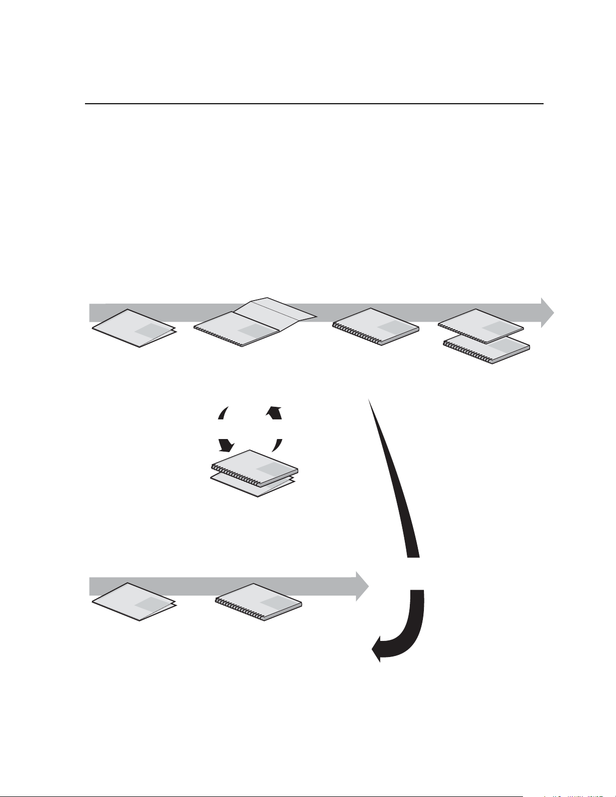
Using the Profile XP Documentation S et
This manual is part of a full set of support documentation for the Profile XP Media
Platform. The following illustrates how to use the Profile XP documentation depending
on the task you are performing .
Path for the Installer
s
ie
r
e
S
Profile XP
P
X
f
o
ly
i
m
Manual
a
F
Grass Valley Group
Release Notes
Contains the latest
information about Profile XP
hardware and software
shipped with your system.
Grass Vall
ey Group
Profile XP
Manual
s
e
i
r
e
S
P
X
f
o
y
l
i
m
a
F
Installation Guide
Contains essential steps for
installing your Profile XP
system with local storage,
using factory default settings.
Use alternate procedures
for shared storage option.
System Guide
Contains the product description
and step-by-step instructions for
modifying system settings.
Grass Valley Group
Profile XP
s
e
i
r
e
S
P
X
f
o
y
l
i
Manual
m
a
F
Grass Valley Group
Grass Valley Group
Profile XP
s
e
i
r
e
S
P
X
f
o
y
l
i
Manual
m
a
F
s
e
i
r
e
S
P
X
f
o
Profile XP
y
l
i
Manual
m
a
F
Other Manuals
These manuals include:
- PFC500 Instruction Manual
- PFR500 Instruction Manual
- PFR600 Instruction Manual
- PFR700 Instruction Manual
- Profile XP Service Manual
Path for the Operator
up
s
ie
r
e
S
Profile XP
P
X
f
o
ly
i
m
Manual
a
F
Grass Valley Gro
Release Notes
Contains the latest
information about Profile XP
hardware and software
shipped with your system.
ey Group
Grass Vall
Grass Valley Group
Profile XP
Profile XP
Manual
s
e
i
r
e
S
P
X
f
o
y
l
i
Manual
m
a
F
s
e
i
r
e
S
P
X
f
o
y
il
m
a
F
Open SAN
Instruction Manual and Release Notes
Contains instructions for installing storage
that is shared by multiple Profile XP systems.
s
e
i
r
e
Profile XP
Manual
S
P
X
f
o
y
l
i
m
a
F
Grass Valley Group
User Manuals
Contains complete instructions for using
Profile applications. These manuals include:
- Profile XP User Manual
- Other user manuals you received with
optional Profile applications.
Installers consult
the User Manuals
as needed.
23 July 2004 Profile XP System Guide 9
Page 10

Preface
Manual Descriptions
• Installation Guide (for your P rofi le XP Mode l) Pr ovi des st ep-b y-ste p ins tru ction s
for installing the Profile XP Media Platform using factory default settings for all
record/play channels. Factory default settings are indicated within the guide. After
installing the Profile XP system using this installation guide, you can refer to this
Profile XP System Guide to customize system settings for your installation.
Profile XP User Manual Contains complete instructions for using Profile
•
applications to operate the Profile XP Media Platform.
Profile XP Service Manual Contains information for servicing the Profile XP
•
Media Platform and monitoring systems using NetCentral II Lite. Procedures are
included for following tasks:
- Setting up and using NetCentral to monitor and diagnose problems on local and
remote Profile XP systems.
- Problem analysis using symptom, possible problem, solution tables.
- Runnin g dia g nostics
- Replacing field replaceable units.
• NetCentral User Guide Contains information for using NetCentral to monitor
various types of broadcast equipment, including Profile XP systems, from a central
monitoring station.
Profile XP Release Notes Contains the latest information about the Profile
•
hardware and the software release shipped on your system. This information
includes software specifications and requirements, feature changes from the
previous releases, helpful system administrative information, and any known
problems.
PFC500 Instruction Manual Contai ns informatio n for servicing t he PFC500 Fibre
•
Channel RAID Chassis including step-by-step procedures for replacing field
replaceable units.
PFR500 Instruction Manual Contai ns informatio n for servicing t he PFR500 Fibre
•
Channel RAID Chassis including step-by-step procedures for replacing field
replaceable units.
PFR600 Instruction Manual Contai ns informatio n for servicing t he PFR600 Fibre
•
Channel RAID Chassis including step-by-step procedures for replacing field
replaceable units.
PFR700 Instruction Manual Contai ns informatio n for servicing t he PFR700 Fibre
•
Channel RAID Chassis including step-by-step procedures for replacing field
replaceable units.
Open SAN Instruction Manual Contains instructions for installing sto rage that is
•
shared by multiple Profile XP systems.
10 Profile XP System Guide 23 July 2004
Page 11

How this manual is organized
The Profile XP System Guide is organized a round the task s you’ll be performing to
customize the Profile XP settings to meet your system needs. Y ou can see this reflected
in the chapter titles chosen for this manual. The following identifies and describes the
chapters included in this manual:
Chapter 1 - Introducing the Profile XP Media Platform
Introduces the Profile XP Media Platform. You can read this chapter to get familiar with
the Profile XP key features and system components. Also included is a brief architectural
overview o f the Profile XP system.
Chapter 2 - Working with Configuration Manager
Describes the Configuration Manager user interface and functionality. Configuration
Manager is the application used to configure and manage the Profile XP system.
Chapter 3 - Working with RAID Storage Using GVG Disk Utility
Describes how to set up local storage for the Profile XP Media Platform. Procedures are
included for configurations with PFC500, PFR500, PFR600, and PFR700 Fibre
Channel RAID Chassis and expansion chassis, and for storage systems with the optional
second controller board.
Chapter 4 - Adding or Removing Channels
Describes the basics of adding, configuri ng, or removing channe ls. Information on
advanced channel settings are referenced to chapters 5 through 7.
How this manual is organized
Chapter 5 - Modifying a Channel: Video Settings
Describes how to modify the video settings for a channel.
Chapter 6 - Modifying a Channel: Audio Settings
Describes how to modify the audio settings for a channel.
Chapter 7 - Modifying a Channel: Timecode Settings
Describes how to modify the timecode settings for a channel.
Chapter 8 - Modifying a Channel: Ancillary Data
Describes how to modify the ancillary data settings for a channel.
Chapter 9 - Managing Optional Licenses
Describes how to request and add optional software licenses to enable features such as
the Agile Output.
Chapter 10 - Controlling the Profile XP Remotely
Describes how to set up the Profile XP Media Platform for the control mode you want
to use: remote control protocol over RS-42 2 or remote applications over Ethernet.
Chapter 11 - Setting up a Simple Network
Describes how to set up a simple network of Profile XP systems. Procedures are
included for setting up the Windows NT network and both Profile XP video network
options.
Chapter 12 - Solving Common S etup Problems
Provides help for solving common set up problems that occur when Profile XP features
or signal requirements are not understood.
Appendix A - Electrical and Environmental Specifications
This appendix consists of electrical and environmental specifications.
23 July 2004 Profile XP System Guide 11
Page 12

Preface
Appendix B - Connector Pin-outs
This appendix identifies connectors and the signals present on the pins of those
connectors.
Appendix C - Rack Mounting Information and Rear Panel Drawings
This appendix provides rack mounting information for the Profile XP system and
peripheral equipment. Also provided are rear panel illustrations for the Profile XP and
peripheral equipment.
Getting more information
In addition to printed documents, Profile XP product information is available in on-line
manuals and the Profile XP help system. Use these as additional sources for information.
On-line manuals
Electronic versions of the following manuals are located on the system drive of your
Profile XP Media Platform and on the Profile XP software CD-ROM.
• Installation Guide (for your model)
• Profile XP System Guide
• Profile XP User Manual
• Profile XP Release Notes
• Profile XP Service Manual
• NetCentral User Guide
• PFC 500 Instruction Manual
• PFR 500 Inst r uct ion Manual
• PFR 600 Inst r uct ion Manual
• PFR 700 Inst r uct ion Manual
You can view these manuals using Adobe Acrobat Reader which is also pre-installed on
your Profile XP system.
On-line Help
Contains all the information in the Profile XP System Guide, optimized for use on-line.
You can access on-line help by choosing the Help menu, or by clicking the Help button
in a dialog box.
12 Profile XP System Guide 23 July 2004
Page 13

Grass Valley Product Support
To get technical assistance, check on the status of problems, or report new problems,
contact Grass Valley Product Support via e-mail, the Web, or by phone or fax.
Web Technical Support
To access support information on the Web, visit the product support Web page on the
Grass Valley Web site. You can download software or find solutions to p roblems by
searching our Frequently Asked Questions (FAQ) database.
World Wide Web: http://www.thomsongrassvalley.com/support/
Technical Support E-mail Address: gvgtechsupport@thomson.net.
Phone Support
Use the following information to contact product support by phone during business
hours. Afterhours phone support is available for warranty and contract customers.
United States (800) 547-8949 (Toll Free) France +33 (1) 34 20 77 77
Latin America (800) 547-8949 (Toll Free) Germany +49 6155 870 606
Grass Valley Product Support
Eastern Europe +49 6155 870 606 Greece +33 (1) 34 20 77 77
Southern Europe +33 (1) 34 20 77 77 Hong Kong +852 2531 3058
Middle East +33 (1) 34 20 77 77 Italy +39 06 8720351
Australia +61 3 9721 3737 Netherlands +31 35 6238421
Belgium +32 2 3349031 Poland +49 6155 870 606
Brazil +55 11 5509 3440 Russia +49 6155 870 606
Canada (800) 547-8949 (Toll Free) Singapore +656379 1390
China +86 106615 9450 Spain + 34 91 512 03 50
Denmark +45 45968800 Sweden +46 87680705
Dubai + 971 4 299 64 40 Switzerland +41 (1) 487 80 02
Finland +35 9 68284600 UK +44 870 903 2022
Authorized Support Representative
A local authorized support representative may be available in your country. To locate
the support representative for your country, visit the product support Web page on the
Grass Valley Web site.
Profile Users Group
You can connect with other Profile XP Media Platform users to ask questions or share
advice, tips, and hints. Send e-mail to profile -users@ thomson .net to join the community
and benef it from the experience of others.
23 July 2004 Profile XP System Guide 13
Page 14

Preface
14 Profile XP System Guide 23 July 2004
Page 15

Safety Summaries
General Safety Summary
Review the following safety precautions to avoid injury and prevent damage
to this product or any products connected to it.
Only qualified personnel should perform service procedures.
While using this product, you may need to access other parts of the system.
Read the General Safety summary in other system manuals f or warnings an d
cautions related to operating the system.
Injury P r e cautions
Use Proper Power
Cord
Ground the Product This product is grounded through the grounding conductor of the power
Do Not Operate
Without Covers
Do Not operate in
Wet/Damp
Conditions
Do Not Operate in an
Explosive
Atmosphere
Avoid Exposed
Circuitry
To avoid fire hazard, use only the power cord specified for this product.
cord. To avoid electric shock, the grounding conductor must be connected
to earth ground. Before making connections to the input or output terminals
of the product, ensure that the product is pr operly grounded.
To avoid electric shock or fire hazard, do not operate this product with
covers or pa nels rem oved.
To avoid electric shock, do not operate this product in wet or damp
conditions.
To avoid injury or fire hazard, do not operate this product in an explosive
atmosphere.
To avoid injury, remove jewelry such as rings, watches, and other metallic
objects. D o not to uc h exp os e d con ne cti o ns and c ompon e nts wh en po we r is
present.
23 July 2004 Profile XP System Guide 15
Page 16

Safety Summaries
Product Damage Precautions
Use Proper Power
Source
Provide Proper
Ventilation
Do Not Operate With
Suspected Failures
Battery
Replacement
Do not operate this product from a power source that applies more than the
voltage sp e c i f ied.
To prevent product overheating, provide proper ventilation.
If you suspect there is damage to this product, have it inspected by qualified
service personnel.
To avoid damage, replace only with the same or equivalent type
recommended by the circuit board manufacturer. Dispose of used battery
according to the circuit board manufacturer’s instructions.
Safety Terms and Symbols
Terms in This
Manual
!
!
These terms may appear in this manual:
WARNING: Warning statements identify conditions or practices that can
result in personal injury or loss of life.
CAUTION: Caution statements identify conditions or practices that can
result in damage to the equipment or other property.
Terms on the
Product
Symbols on the
Product
!
These terms may appear on the product:
DANGER indicates a personal injury hazard immediately accessible as one
reads the marking.
WARNING indicates a personal injury hazard not immediately accessible
as you read the marking.
CAUTION indicates a hazard to property including the product.
The following symbols may appear on the product:
DANGER high voltage
Protective ground (earth) terminal
ATTENTION – refer to manual
16 Profile XP System Guide 23 July 2004
Page 17

Service Safety Summary
Do Not Service
Alone
Disconnect Power To avoid electric shock, disconnect the main power by means of the power
Use Care When
Servicing With
Power On
Do not perform internal service or adjustment of this product unless another
person capable of rendering first aid and resuscitation is present.
cord or, if provided, the power switch.
Dangerous voltages or currents may exist in this product. Disconnect power
and remove battery ( if applicable) before removing protective p anels,
soldering, or replacing components.
To avoid electric sho ck, do not touch exposed connecti ons
Certifications and Compliances
Canadian Certified
Power Cords
FCC Emission
Control
Canadian approval includes the products and power cords appropriate for
use in the North Amer ica power ne twork. All other powe r cords supp lied are
approved for the country of use.
This equipment has been tested and found to comply with the limits for a
Class A digital device, pursuant to Part 15 of the FCC Rules. These limits
are designed to provide reasonable protection against harmful interference
when the equipment is operated in a commercial environment. This
equipment generates, uses, and can radiate radio frequency energy and, if
not installed and used in accordance with the instruction manual, may cause
harmful interference to radio communications. Operation of this equipment
in a residential area is likely to cause harmful interference in which case the
user will be required to correct the interference at his own expense. Changes
or modific ation s not ex press ly app roved by Th omson Br oadca st an d Media
Solutions Inc. can affect emission compliance and could void the user’s
authority to operate this equipment.
Canadian EMC
Notice of
Compliance
Canadian Certified
AC Adapter
EN55022 Class A
Warning
23 July 2004 Profile XP System Guide 17
This digital apparatus does not exceed the Class A limits for radio noise
emissions from digital apparatus set out in the Radio Interference
Regulations of the Canadian Department of Communications.
Le présent apparei l numérique n’émet pas de bruit s radioélectriques
dépassant les limites applicables aux appareils numériques de la classe A
préscrites dans le Règlement sur le brouillage radioélectrique édicté par le
ministère des Communications du Canada.
Canadian approval includes the AC adapters appropriate for use in the
North America power network. All other AC adapters supplied are
approved for the country of use.
For products that comply with Class A. In a domestic environment this
product may cause radio interference in which case the user ma y be
required to take adequate measures.
Page 18

Safety Summaries
Laser Compliance
Laser Safety
Requirements
The device used in this product is a Class 1 certified laser p roduct. Operating
this product outside specifications or altering its original d esign may r esult
in hazardous radiation exposure, and may be considered an act of modifying
or new m anufact uring o f a lase r produc t unde r U.S. r egulat ions co ntained in
21CFR Chapter 1, subchapter J or CENELEC regulations in HD 482 S1.
People performing such an act are required by law to recertify and reidentify
this product in accordance with provisions of 21CFR subchapter J for
distribution within the U.S.A., and in accordance with CENELEC HD 482
S1 for distribution within countries using the IEC 825 standard.
Laser Safety Laser safety in the United States is regulated by the Center for Devices and
Radiological Health (CDRH). The laser safety regulations are published in
the “Laser Product Performance Standard,” Code of Federal Regulation
(CFR), Title 21, Subchapter J.
The International Electrotechnical Commission (IEC) Standard 825,
“Radiation of Laser Products, Equipment Classification, Requirements and
User’s Gui de,” gove rns laser pr oducts out side the Uni ted States . Europe a nd
member nations of the European Free Trade Association fall under the
jurisdiction of the Comité Européen de Normalization Electrotechnique
(CENELEC).
FCC Emission
Limits
This device complies with Part 15 of the FCC Rules. Operation is s ubject to
the following two conditions: (1) This device may not cause harmful
interference, and (2) this device must accept any interference received,
including interference that may cause undesirable operation.
Certification
Category Standard
Safety Designed/tested for compliance with:
UL1950 - Safety of Information Technology Equipment, including Electrical Business
Equipment (Third Edition, 1995)
IEC 950 - Safety of Information Technology Equipment, including Electrical Business
Equipment (Second edition, 1991)
CAN/CSA C22.2, No. 950-95 - Safety of Information Technology Equipment,
including Electrical Business Equipment
EN60950 - Safety of Information Technology Equipment, including Electrical Business
Equipment
18 Profile XP System Guide 23 July 2004
Page 19

Chapter
1
Introducing the Profile XP Media
Platform
The Profile XP Media Platform provides a multi-channel, high bandwidth platform for
the storage and manipulation of video and audio in professional applications. The
Profile XP Media Platform has a wide range of capabilities, from a stand alone digital
disk recorder to being part of a large network of video servers. The Profile XP Media
Platform can be used in a wide variety of applications including spot insertion, program
delay, store and forward, and multi-channel replay.
Profile XP Media Platform feat ures
Encoders and decoders in the PVS1000 models process standard definition MPEG-2
video, while encoders and decoders in the PVS2000 models process high definition
MPEG-2 video.
The PVS1100 Series uses video codecs to process video. Y ou can configure each of the
codecs to encode and decode video using the DVCAM, DVCPRO or MPEG-2
compression standards. The PVS1100 Series processes video using DVCAM,
DVCPRO 25, and MPEG-2 at bits rates up to 25 Mb/s. The 50 Mb/s software option
allows you to proces s vid eo us ing D VCP RO 50, and M PEG-2 at bi t ra tes up to 50 Mb /s,
including the D10 format at 30, 40, or 50 Mb/s. You to play clips of any of these
compressi on t ype s th ro ug h an y co de c wi th out an y co nfi g ura tion c hang es. For ex ampl e,
a DVCPRO 50 can immediately follow an MPEG-2 clip at 12 Mb/s on any playout
channel. The only limitation is that you cannot create or play master clips (complex
movies) that include more than one compression type.
The PVS3000 Series combines both standard and high definition capabilities in a single
Profile XP Media Platform. You can record and play SD clips in all the
PVS1100-supported formats on your SD channels, and concurrently record and play HD
clips in all the PVS2000-supported fo rmats on your HD channels.
The PVS3500 Series extends these capabilities to allow you to play both SD and HD
MPEG-2 4:2 :0 clips thr ough an HD dec oder . Y o u can play both 1080i and 72 0p HD clips
through the same decoder. Clips are played out in the format specified for the output
assigned to the channel, but all HD outputs on a system must be set to the same standard
(1080i or 720p). The decoder can play out on either a standard definition output or a high
definition output.
All clips are either up- or down-converted appropriately to play on that output, and their
aspect ratios are adjusted according to your custom settings. As with the PVS1100, you
cannot create or play master clips (complex movies) that include both standard and high
definition material.
This definition-independent software option (Agile Output) can be installed on a
PVS2000 or a PVS3000, althou gh up- or dow n-con versi on is de pend ent on your out put
hardwar e. For example, your PVS2000 cannot down-convert HD material without
adding standard definition output cards.
23 July 2004 Profile XP System Guide 19
Page 20

Chapter 1 Introducing the Profile XP Media Platform
All inputs, both standard and high definition, can record ancillary data. When you play
these clips, the ancillary data is inserted on the specified lines. If your chosen output does
not support as much ancillary data as was recorded on each line, the data is truncated at
the maximum for that output. This occurs, for example, when you play HD clips on an
SD output.
20 Profile XP System Guide 23 July 2004
Page 21

Features common to all med ia platf or ms
• 16 (8 AES Pairs)/ 32 (16 AES pairs) channel audio - AES/EBU, embedded or
analog uncompressed audio, Dolby E and AC-3 compressed audio
• 600 Mb/s Syste m Ba ndwidth
• Redundant power supply, Windows NT system disk, cooling fans for reliability
• Fibre Channel attached high performance RAID storage
• Storage capability supported includes distributed storage for hundreds of channels
as well as centralized storage for up to 64 channels
• NetCentral™ provides remote error reporting and monitoring via SNMP
• High speed Fibre Channel networking up to 250 Mb/s
• 100BaseT Ethernet networking up to 30 Mb/s
• Remote control including:
- Remote Applications over Ethernet
- RS-422 control protocol including AMP, VDCP, Odetics, BVW, or Profile
protocols.
Profile XP M edia Platform features
- GPI Trigger (8 I/O)
PVS1000 features include:
• Up to 8 standard definition (SD) channels of broadcast-quality video
PVS1000 Series channel configurations by model
Model
Number
PVS1022 1 1 2 in/2 out
PVS1024 1 2 2 in/ 4 out
PVS1026 1 3 2 in/6 out
PVS 1042 2 1 4 in/2 out
PVS1044 2 2 4 in/4 out
PVS1062 3 1 6 in/2 out
PVS 1002 0 1 0 in/2 out
PVS 1004 0 2 0 in/4 out
PVS 1006 0 6 0 in/6 out
PVS1008 0 4 0 in/8 out
a.
MPEG Encoder and Decoder boards in PVS1000 series are Standard
Definition.
Number of MPEG
Encoder Boards
• MPEG-2 4:2:2 @ Main Level from 4-50 Mb/s, long GoP ( for SD)
Number of MPEG
a
Decoder Boards
Channel
Configuration
• SMPTE 259M, 270MB Serial Digital I/O (Analog monitor optional)
• 525/60 or 625/50 operation: accepts NTSC, PAL
23 July 2004 Profile XP System Guide 21
Page 22
Chapter 1 Introducing the Profile XP Media Platform
PVS1100 features include:
• Up to 8 standard definition (SD) channels of broadcast-quality video
PVS1100 Series channel configurations by model
Model
Number
PVS1102 2 2 play/record
PVS1104 4 4 play/record
PVS1106 6 6 play/record
PVS1108 8 8 play/record
Number of video
codecs
Channel
Configuration
• DVCAM video compression
• DVCPRO 25 video compression
• DVCPRO 50 video compression with 50 Mb/s option
• MPEG-2 4:2:0 @ Main Level from 4 to 15 Mb/s, long GoP
• MPEG-2 4: 2:2 @ Main Level from 4-25 Mb/s, l ong GoP or up to 50 Mb/s with
50 Mb /s option
• MPEG-D10 I-frame at 30, 40, or 50 Mb/s CBG (requires 50 Mb/s option)
• Back-to-back playout of all formats on any codec
• SDTI (optional): two channels, each configurable as input or output. DVCPRO 25
input at 1x, 2x, 4x; output at 1x, 4x. DVCPRO 50 input at 1x, 2x; output at 1x.
• New real-time processor board with improved processing capacity — provides
greater bandwidth for fibre channel transfers, concurrent channel operations, etc.
• 525/60 or 625/50 operation: accepts NTSC, PAL
22 Profile XP System Guide 23 July 2004
Page 23

PVS2000 features include:
• Up to 4 high definition (HD) channels of broadcast-quality video
PVS2000 Series channel configurations by model
Profile XP M edia Platform features
Model
Number
PVS2002 0 1 0 in/2 out
PVS2004 0 2 0 in/4 out
PVS2012 1 1 1 in/2 out
PVS2013 1 2 1 in/ 3 out
PVS2022 2 2 2 in/2 out
Number of HD
Encoder Boards
Number of HD
Decoder Boards
Channel
Configuration
• MPEG-2 4:2:0 @ Main Level from 20-80 Mb/s, long GoP (for HD)
• HD: SMPTE 292M, 1.485 Gbs Serial Digital I/O (includes downconverted SD SDI
and composite analog monitor with text overlay and timecode burn-in)
• Up-conversion of MPEG-2 4:2:0 clips with aspect ratio configuration (requires
Definition Independent option)
• 1080i and 720p line rates for HD, 50, 59.94, and 60 fps, accepts house black and
tri-level sync reference
23 July 2004 Profile XP System Guide 23
Page 24

Chapter 1 Introducing the Profile XP Media Platform
PVS3000 features include:
• Up to 3 high definition (HD) channels of broadcast-quality video
• Up to 4 standard definition (SD) channels of broadcast-quality video
PVS3000 Series channel configurations by model
Model
Number
PVS3004 2 0 2 2 play/record, or
PVS3014 2 1 2 2 play/record, or
PVS3024 4 0 2 2 play/record, or
PVS3034 4 1 2 2 play/record, or
Number of SD
video codecs
Number of HD
MPEG Encoders
Number of HD
MPEG Decoders
SD Channel
Configuration
1 in/1 out
1 in/1 out
2 in/2 out
2 in/2 out
• MPEG-2 4:2:0 @ Main Level from 20-80 Mb/s, long GoP (for HD)
• HD: SMPTE 292M, 1.48 5 Gbs Seria l Digital I /O (includ es downconv erted SD SDI
and composite analog monitor with text ove rl ay and timecode burn-in)
• 1080i and 720p line rates for HD, 50, 59.94, and 60 fps, accepts house black and
tri-level sync reference
• DVCAM video compression (for SD)
• DVCPRO 25 video compression (for SD)
• DVCPRO 50 video compression with 50 Mb/s option (for SD)
• MPEG-2 4:2:0 @ Main Level from 4 to 15 Mb/s, long GoP (for SD)
HD Channel
Configuration
0 in/2 out
1 in/2 out
0 in/2 out
1 in/2 out
• MPEG-2 4: 2:2 @ Main Level from 4-25 Mb/s, l ong GoP or up to 50 Mb/s with
50 Mb/s option (for SD)
• MPEG-D10 I-frame at 30, 40, or 50 Mb/s CBG with 50 Mb/s option (for SD)
• Back-to-back playout of all SD formats on any SD codec
• Up-conversion of SD MPEG-2 4:2:0 clips with aspect ratio configuration (requires
Definition Independent option, Agile Output)
• Down-conversion of HD clips with aspect ratio configuration (requires Definition
Independent option, Agile Output)
24 Profile XP System Guide 23 July 2004
Page 25

PVS3500 features include:
• Up to 3 high definition (HD) channels of broadcast-quality video
• Up to 4 standard definition (SD) channels of broadcast-quality video
PVS3500 Series channel configurations by model
Profile XP M edia Platform features
Model
Number
PVS3502 0 0 2 0 in/1 out,
PVS3504 0 0 4 0 in/2 out,
PVS3504H 0 0 4 0 in/0 out 0 in/4 out
PVS3512 0 1 2 0 in/1out,
PVS3514 0 1 4 0 in/2 out
PVS3522 2 0 2 2 play/record, or
PVS3524 2 0 4 2 play/record, or
PVS3532 2 1 2 2 play/record, or
PVS3534 2 1 4 2 play/record, or
Number of SD
video codecs
Number of HD
MPEG Encoders
Number of HD
MPEG Decoders
SD Channel
Configuration
down-converted
down-converted
down-converted
down-converted
1 in/1 out
2 in/2 out
1 in/1 out
2 in/2 out
HD Channel
Configuration
0 in/1 out
0 in/2 out
1 in/2 out
1 in/2 out
0 in/2 out
0 in/2 out
1 in/2 out
1 in/2 out
• MPEG-2 4:2:0 @ Main Level from 20-80 Mb/s, long GoP (for HD)
• HD: SMPTE 292M, 1.485 Gbs Serial Digital I/O (includes downconverted SD SDI
and composite analog monitor with text overlay and timecode burn-in)
• 1080i and 720p line rates for HD, 50, 59.94, and 60 fps, accepts house black and
tri-level sync reference
• DVCAM video compression (for SD)
• DVCPRO 25 video compression (for SD)
• DVCPRO 50 video compression with 50 Mb/s option (for SD)
• MPEG-2 4:2:0 @ Main Level from 4 to 15 Mb/s, long GoP
• MPEG-2 4:2:2 @ Main Level from 4-25 Mb/s, long GoP or up to 50 Mb/s with
50 Mb/s option (for SD)
• MPEG-D10 I-frame at 30, 40, or 50 Mb/s CBG with 50 Mb/s option (for SD)
• Back-to-back playout of all SD formats on any SD codec
• Up-conversion of SD MPEG-2 4:2:0 clips with aspect ratio configuration
• Down-conversion of HD clips with aspect ratio configuration
23 July 2004 Profile XP System Guide 25
Page 26

Chapter 1 Introducing the Profile XP Media Platform
About channels and factor y defau lt confi gu ration
Profile applications use channels to control disk recording and playback. A channel
defines a grouping of video, audio, and timecode resources and is identified by a unique
name. Profile XP software supports three channel types: Recorder channel, Player
channel, or Player/Recorder channel.
Your Profile XP system is shipped with default Recorder, Player, or Recorder/Player
channels. These default channels are named Vtr1, Vtr2, Vtr3 and so on. The following
table describes the video and audio connections you’ll make for the channel types. The
Installation Guide contains specifics about the type and number of default channels in
your Profile XP model, and their video and audio I/O connections.
Default channel
type
Recorder 1 SDI or HD-SDI
Player 1 SDI or HD-SDI
Player/Recorder 1 SDI or SDTI video
a.
The number of audio I/Os is determined by your Profile XP model and the number of Audio boards
installed. For SDTI, audio is part of the data stream.
b.
Available on the PVS1000 and PVS1100 Series only if the optional Video Monitor board is
installed. Input monitoring of SDTI video is not available. Input monitoring is always available as
a connection on the HD-SDI board.
Video I/O
connections
video input
1 analog monitor
video output
input and output
1 analog monitor
Audio connections
2, 4, or 8 audio I/Os Uses the internal
b
2, 4, or 8 audio I/Os Recorded timecode is
2, 4, or 8 audio I/Os Uses the internal
b
a
Timecode I/O
timecode generator.
used to generate VITC on
the SDI video output or
insert VITC in the
HD-SDI output
timecode generator.
Recorded timecode is
used to generate VITC on
the SDI video output.
You can use the information in this System Guide to modify default channel settings to
satisfy the needs of your system. For more information about channels, refer to
Chapter 4, Adding or Remo ving Channels.
26 Profile XP System Guide 23 July 2004
Page 27

Video compression for standard de fini tion
Video compression for stan dar d defi ni tion
The Profile XP Media Platform uses a variety of standard definition video compression
formats: MPEG-2, DVCPRO 25, DVCPRO 50, and MPEG D10. Files of different
compression types can be stored concurrently on the media platform, and accessed
concurrently by different channels.
MPEG-2 support
The PVS1000 uses MPEG-2 4:2:2 @ Main Level encoding with selectable bit rates from
4 Mb/s to 50 Mb/s. The additional chroma resolution that 4:2:2 sampling gives provides
good multi-generation capability as well as up-conversion quality. 4:2:0 chroma
sampling is also available, allowing the creation of clips that can be up converted to HD
resolutions on an HD decoder with the Definition Independent option, which is included
on the PVS 3500.
Seamless play and cuts editing at any bit rate and any GoP is made possible by the
Profile XP dual MPEG decoder architecture that allows storage efficiencies of a long
GoP and maintains the ability to cut on any frame and play clips back-to-back
seamlessly. This provides all of the advantages of long GoP encoding, without the
limitations.
The PVS1100 provides MPEG-2 4:2:2 support at bit rates up to 25 Mb/s, and up to
50 Mb/s with the 50 Mb/s option. The PVS1100 also provides MPEG D10 compatibility .
MPEG D10 is an MPEG format that was developed for tape. It is characterized by a
selectable fixed bit rate (3 0, 40, or 50 Mb/s) and constraine d byte GoP (CBG), that
prevents the size of a field from exceeding the physical size of the tape scan.
DVCPRO support
The PVS1100 provides DVCPRO 25 and optional DVCPRO 50 compression formats.
These formats improve work flow by allowing the transfer of material between other
equipment and the Profile XP media platform without re-encoding the compressed
video.
Video compression for hi gh defi ni tion
The PVS2000 uses MPEG-2 4:2:0 @ Main Level encoding with selectable bit rates from
20 Mb/s to 80 Mb/s.
Serial Data Transport Interface (SDTI)
SDTI is available as an option to the PVS1100 Series. The SDTI board provides two
channels, each of which you can configure to be an input or output. The SDTI board
accepts input of DVCPRO 25 video at 1x, 2x, and 4x real time, and input of DVCPRO
50 video at 1x and 2x real time. SDTI output of DVCPRO 25 is selectable at 1x or 4x;
output of DVCPRO 50 at 1x. This version of system software supports DVCPRO 25 and
DVCPRO 50 as SDTI video formats.
23 July 2004 Profile XP System Guide 27
Page 28

Chapter 1 Introducing the Profile XP Media Platform
Fibre Channel RAID storage
IMPORTANT: If your Profile XP Media Platform is part of an Open SAN, refer to
the Open SAN Instruction Manual for information about media storage.
The Profi le XP Media Platform s upports two storage options, distributed and
centralized.
Distributed Storage
Distributed storage is implemented using RAID storage systems connected directly to
each Profile XP Media Platform. Each Profile XP system accesses media on its own
dedicated storage system. Increased availability to storage is provided by an optional
redundant RAID controller board available for the RAID storage system. If the primary
connection fails, the system automatically switches over and uses the redundant
connection. Media is shared in the distributed storage model by transferring the media
files over an optional video network adapter. With Profile streaming protocol, media
playout can begin before the video network transfer is complete.
Centralized Storage
The Profile XP centralized storage solution, the Open SAN, is implemented using a
Fibre Channel switch fabric to connect all RAID storage chassis and Profile XP Media
Platforms. Centralized storage provides multiple Profile XP Media Platforms
simultaneous access to a common pool of media. As in distributed storage, a redundant
Fibre Channel connection option is available to provide a redundant path to the
centralized storage pool in case the primary path fails.
Fibre Channel and/or Ethernet IP Video Networks
The Profile XP family offers true IP netw orking of m edia files over Fibre Channel or
Ethernet.
• Faster than real time transfers (up to 40x) with no generation loss
• Reliable transfers using secure file transfer protocols
• IP networking enables files to be moved between devices or between facilities over
standar d pu bl i c ne tw o rks .
• Profile network streaming enables “play while transferring”
Fibre Channel Streaming enables the file to be used shortly after the destination Profile
starts receiving it — just like you can do with a traditional video router. This eliminates
the traditional drawback of networking in which the file must finish transferring before
a user has access to edit it or play it out.
28 Profile XP System Guide 23 July 2004
Page 29
Front panel controls and indicators
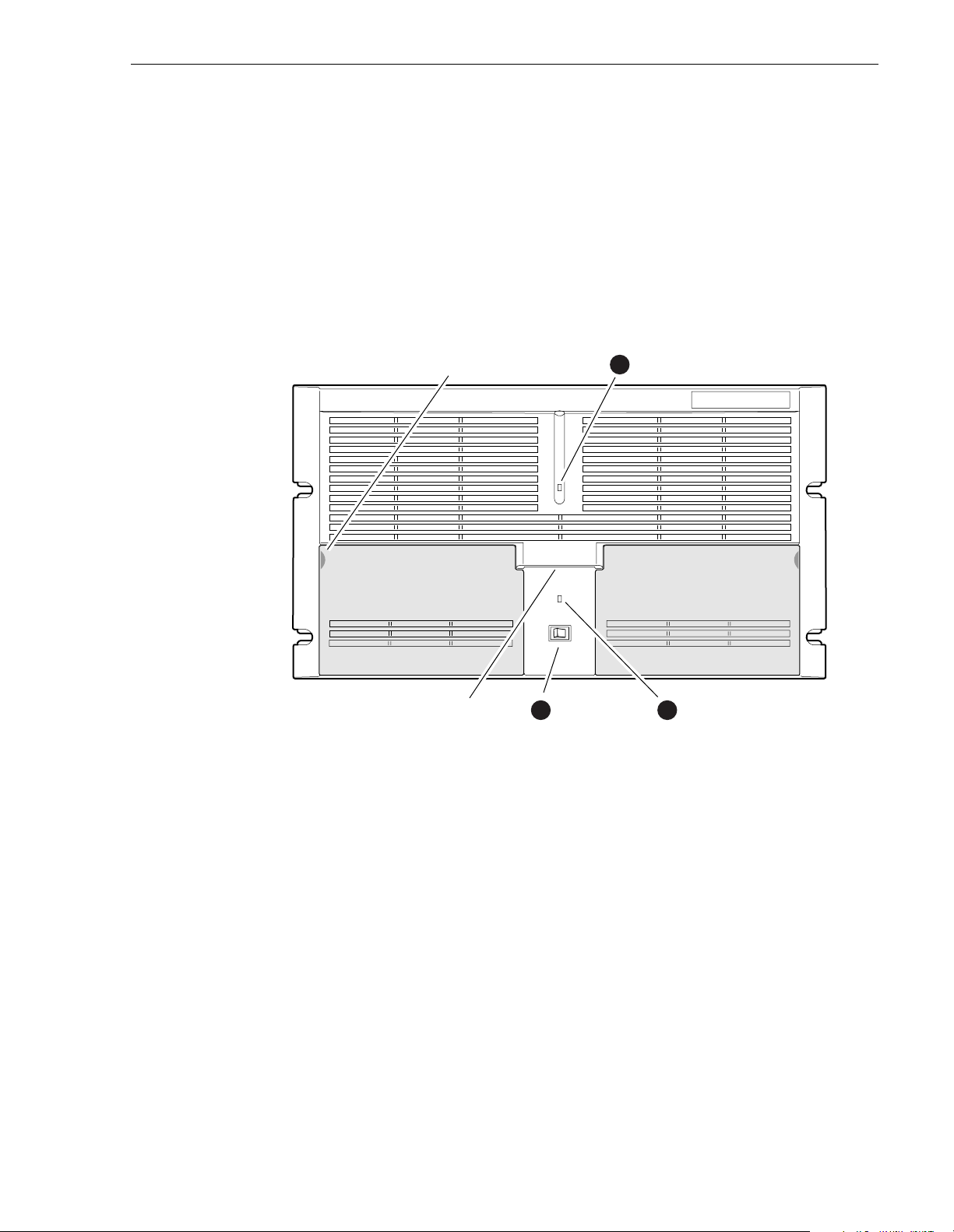
Front panel controls and indicators
The front panel includes the following controls and indicators:
➊ Power-On LED - indicates the standby switch is in the on positio n and that secondary
voltages are present in the chassis.
➋ Standby Switch - provides system On/Off control.
➌ System Fault LED - indicates a system fault exist somewhere in the Profile XP unit.
Pull here to
open (each side)
Accessory
Door
Standby/On
2
Switch
1
Standby/On LED
Accessory
Door
System
3Chassis Pull
Fault LED
0624-5
23 July 2004 Profile XP System Guide 29
Page 30
Chapter 1 Introducing the Profile XP Media Platform
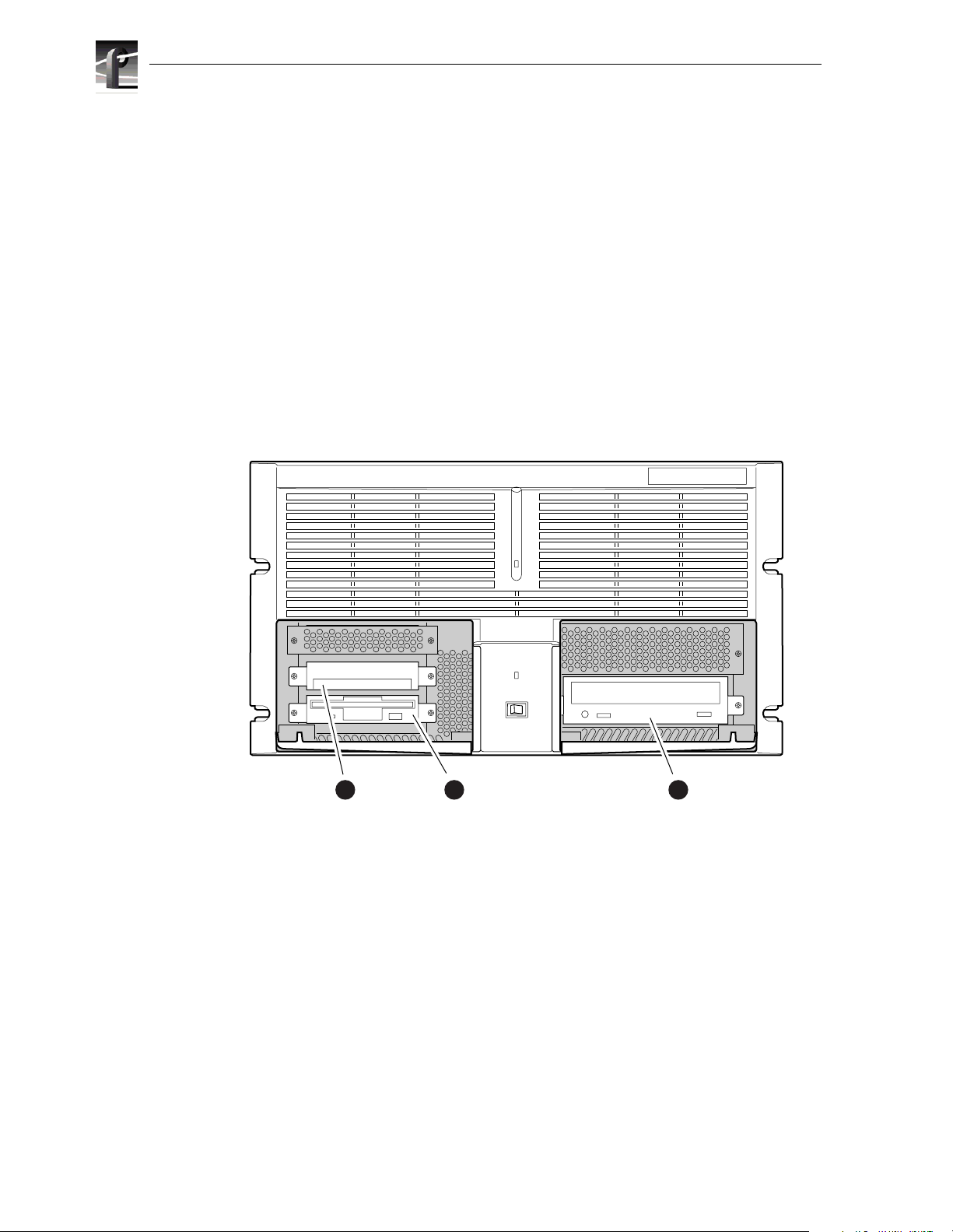
The front panel features two accessory doors that provide access to several storage
devices. The following describes the storage devices installed on the standard Profile XP
system.
➊ System Disk - contains the Windows NT operating system and Profile XP system
software and applications.
➋ 1.44MB F lop py D isk Driv e
➌ CD-ROM Drive - for maintaining the Windows NT operating system and performing
Profile XP system software upg rades.
NOTE: If an accessory door is accidentally dislocated from its hinges, you can
easily pop it back into place.
0624-4
System
1
Disk Drive
30 Profile XP System Guide 23 July 2004
Floppy
2
Disk Drive
CD-ROM
3
Drive
Page 31

Front panel controls and indicators
The following describes the storage devices in a Profile XP system with the redundant
system disk option .
➊ Primary System Drive - contains Windows NT operating system and Profile XP
software and applications.
➋ Mirror System Disk - mirrors primary system disk and provides automatic fail-over
in the event the primary system disk fails.
➌ Drive Mirroring Controller and Indicator Panel -
The Indicator Panel status LEDs indicate the operating mode of the mirroring
system as follows:
- Green - Drives are in Mirror mode
- Red - Drives in Single mode
- Orange - Drive activity
The Buzzer Off switch can be used to silence the buzzer, which sounds under the
following conditions:
- Short beep during power on indicates successful boot-up
- Second beep indicates the mirroring system is running in single mode
- Continuous or intermittent beep to indicate a drive failure
➍ CD-ROM Drive - for maintaining the W in dows NT operating system and performing
Profile XP system software upgrades.
➎ 1.44MB Floppy Disk Drive
DupliDisk
Primary System
1
Disk Drive
Primary
Mirror Status Buzzer
3
DupliDisk
Indicator Panel
Mirrored System
2
Disk Drive
4
CD-ROM
Drive
Superdrive or
5
Floppy Drive
0625-18
23 July 2004 Profile XP System Guide 31
Page 32

Chapter 1 Introducing the Profile XP Media Platform
Rear Panel View
The figure shows the rear panel connectors. Rear panel drawings for peripheral
equipment are located in Appendix C, “Rack Mounting Information and Rear Panel
Drawings”.
Power Cord
Power
Good LED
Optional
Power
Supply
Profile XP Media Platform
Audio
Channels
1-16
Audio
Channels
1-16 (opt.)
SDTI
(opt.)
Video I/O,
VideoOut, or
Video Monitor
FC Disk (Port A)
FC Disk
(Port B)
LTC/
GPI
Monitor
Parallel Port
Com1 (RS-232)
Ethernet
(Windows NT
Network)
Reference In
(Loop-Thru)
Mouse
Keyboard
RS-422
Breakout
Video
network (opt.)
8112-1
32 Profile XP System Guide 23 July 2004
Page 33

Standard accessories
The Profile XP Media Platform is shipped with the following standard accessories:
• Manuals Include:
- Installation Guide
- Profile XP System Guide
- Profile XP User Manual
- Profile XP Service Manual
- Profile XP Release Notes
• Software package which includes the Profile XP Software CD-ROM
• Windows NT software package
• Keyboard and mouse
• I/O Panel and cables (provides LTC, RS-422 & GPI interfaces)
• Power cable
• Rack mounting slides
Standard accessories
• Ethernet cable
• System rebuild CD-ROM
23 July 2004 Profile XP System Guide 33
Page 34

Chapter 1 Introducing the Profile XP Media Platform
Profile XP Media Platform system overview
The Profile XP Media Platform system is an extension to a standard PCI bus-based
Windows NT computer . This standard is enhanced to add functionality and performance
necessary to deliver an industrial grade, broadcast-quality disk-based video server. This
section discusses the major architectural blocks, what they do, and how they
interconnect.
High level bl ock diagram
The Profile XP Media Platform has three subsystems: Application Subsystem, Real
Time Subsystem, and Storage Subsystem.
User Interface, Control,
Configuration
Application
Subsystem
Application Subsystem
The Application Subsystem is a Windows NT computer subsystem. The Application
Subsystem pro vide s a pl atfor m fo r run ning Win dows b ased appl icatio ns f or co nfigu ring
and controlling the Real Time Subsystem both locally and remotely.
Real Time Subsystem
The Real Time Subsystem contains a real time processor and peripheral devices and runs
the VXWorks operating sys te m.T he Real Time Subsystem ma n age s all t he ha rd w are
involved in controlling the flow of video, audio, timecode in and out of the system. This
includes video I/O boards, audio I/O boards, video compression boards, and networking
and storage. The Real Time Subsystem is controlled by applications running on the
Applications Subsystem using Inter-Processor Messaging channels (IPM). It is
responsible for the execution of events on the play timeline.
IPM
Channel
Platform
Resources
Video I/O, Audio I/O,
Media Networking
Real Time
Subsystem
Fibre
Channel
Media
Storage
Subsystem
0624-40
34 Profile XP System Guide 23 July 2004
Page 35

Media Storage Subsystem
IMPORTANT: If your Prof ile XP Media Pl atfor m is pa rt of a n Open SAN , refe r to
the Open SAN Instruction Manual for information about media storage.
The Storage Subsystem is where the video, audio, timecode and other media related data
is stored. This storage system is made up of one or more external RAID level 3 storage
chassis containing Fibre Channel disks. The Profile XP Real Time Subsystem controls
read/write d isk op erat io ns b y se nd ing SCSI pr ot ocol c omma nd s o ver one or m or e F ibr e
Channel links.
Platform Resources
The platform resources provide the infrastructure necessary to operate, interconnect, and
integrate all the Application Subsystem, Real Time Subsystem components. The
elements that comprise the Platform Resources are: Multi-slot PCI bus, video & audio
crosspoint fabric, powe r supply and system cooling.
Board level block diagram
This section describes the Profile XP architecture in more detail using a board level
block diagram. From this discussion you‘ll gain an understanding of the basic signal
flow in the Profile XP system. Use this information when you are installing and setting
up the Profile XP Media Platform.
Board level block diagram
23 July 2004 Profile XP System Guide 35
Page 36

Chapter 1 Introducing the Profile XP Media Platform
P
C
I
B
u
s
Audio Interface Audio Interface
Net.
Net.
SDI
2In/2Out
SDI
4Out
Video
Monitor
NTSC/PAL
Add. I/O Boards
Audio
(Ch1-16)
Audio
(Ch1-16)
Ethernet
Video
Network
Fibre Ch.
Video
Network
Real Time Subsystem
Crosspoint
Examples
Video/Audio
Crosspoint
Fabric
PCI
B
u
s
Video
Compression
(up to 8 channels
total)
MPEG-2
Encoder
(2Ch SD)
MPEG-2
Decoder
(2Ch SD)
Add. Encoder/
Decoder Boards
Real Time
System Board
Real Time
Processor
LTC & GPI
I/Os
Genlock
LTC
4
GPI
8
Ref In
Media Storage Subsystem
Fibre Channel
Disk Interface
Port A Port B
Local or Shared Storage
Applications Subsystem
P
C
I
B
u
s
4
8
8112-3
Applications
Processor
(plus Windows NT)
3.5FDCD HD Mirror
8 CH
RS-422
Interface
I/O
Panel
SVGA
Mouse
Kybd
Ethernet
HD
Video
Embedded
Audio
AES/EBU
Audio
Profile XP
Optional item
Block diagram for PVS1000 standard definition system
36 Profile XP System Guide 23 July 2004
Page 37

NTSC/PAL
SD SDI
HD out
HD in
PCI Bus
HD SDI
HD SDI
HD SDI*
Add. I/O Boards
Real Time Subsystem
Crosspoint
Examples
Not Available when
Embedded Audio is used.
Video
Compression
HD
MPEG-2
Encoder
HD
MPEG-2
Decoder
Add. Encoder/
Decoder Boards
Needed only when
Embedded Audio is used.
Board level block diagram
Media Storage Subsystem
Fibre Channel
Disk Interface
Port A Port B
"
$&
! " # $ % & '
!#
%'
PFC 500 System
(RAID 3 Storage)
PCI Bus
Applications Subsystem
Applications
Processor
(plus Windows NT)
3.5FDCD HD Mirror
SVGA
Mouse
Kybd
Ethernet
HD
Audio Interface Audio Interface
Net.
Net.
Audio
(Ch1-16)
Audio
(Ch1-16)
Ethernet
Video
Network
Fibre Ch.
Video
Network
Real Time
System Board
Real Time
Video/Audio
Crosspoint
Fabric
Processor
LTC & GPI
I/Os
Genlock
*Embedded audio
requires extra SDI board.
LTC
4
GPI
8
Ref In
PCI Bus
Block diagram for PVS2000 high definition system
4
8
0624-65
8 CH
RS-422
Interface
I/O
Panel
Video
Embedded
Audio
AES/EBU
Audio
Profile XP
Optional item
23 July 2004 Profile XP System Guide 37
Page 38

Chapter 1 Introducing the Profile XP Media Platform
PCI Bus
SDTI
2In/2Out
SDI
2In/2Out
SDI
4Out
Video
Monitor
NTSC/PAL
Add. I/O Boards
Audio
(Ch1-16)
Real Time Subsystem
Compression
(up to 8 channels
Crosspoint
Examples
Video
total)
Video
Processor
Board
Codec
Codec
Add. Processor
Boards
Media Storage
Subsystem
Fibre Channel
Disk Interface
Port A Port B
Local or Shared Storage
Applications Subsystem
PCI Bus
Applications
Processor
(plus Windows NT)
3.5FDCD HD Mirror
SVGA
Mouse
Kybd
Ethernet
HD
Audio Interface Audio Interface
Net.
Net.
Audio
(Ch1-16)
Ethernet
Video
Network
Fibre Ch.
Video
Network
Video/Audio
Crosspoint
Fabric
Real Time
System Board
Real Time
Processor
LTC
LTC & GPI
I/Os
Genlock
PCI Bus
4
GPI
8
Ref In
Block diagram for PVS1100 standard definition system
4
8
8112-4
8 CH
RS-422
Interface
I/O
Panel
Video
Embedded
Audio
AES/EBU
Audio
Profile XP
Optional item
38 Profile XP System Guide 23 July 2004
Page 39

Motherboard
The Profile XP system motherboard contains 14 board slots. Each slot includes a
connection to the system PCI bus and the Video/Audio Transport Fabric. The
Video/Audio transport fabric is an integrated 96x96 crosspoint switch which provides
uncompressed video ( CCIR601) an d audio (24bi t ) routing.
Applications Subsystem
The Applications Subsystem is a Windows NT computer system and includes the
following components:
Application Processor Board
The Application Engine is a standard NLX single board computer. The Application
Subsystem p rov ides a platf orm f or run ning W ind ows based a pplic ation s for confi guri ng
and controlling the Real Time Subsystem both locally and remotely. Rear panel I/O
includes:
• Mouse, Keyboard, and SVGA Connectors
• One Serial Port
• One Parallel Port
Board level block diagram
• Two USB Ports
• Audio Line Level IN/OUT, and Mic Input
• 10/100BASE -T RJ -45 Ethernet P ort
RS422 Board
This RS-422 adapter is installed as part of the Applications Processor system under
Windows NT . Control applications running on the Application Processor receive control
commands from a remote protocol listener that monitors the RS-422 ports.
23 July 2004 Profile XP System Guide 39
Page 40

Chapter 1 Introducing the Profile XP Media Platform
Real Time Subsystem
The Real Time Subsystem includes the following components:
Real Time Sy stem
The Real Time System board contains a real time processor and peripheral devices. A
second generation of this board, Real Time System II, is now used for all Profile XP
models. The RTP-II board requires Profile System Software v. 5.0 or higher. This board
manages all the hardware involved in controlling the flow of video, audio, timecode in
and out of the system. This includes video I/O boards, audio I/O boards, video
compression boards, and networking and storage. Other board functionality includes:
• Generation of system clocks for SD (27MHz) and HD (either 37.0879 or 37.125
Mhz)
• Generation of frame reference pulses
• Ability to lock system clocks and frame reference pulses to tri-level sync or to
NTSC/PAL bi-level sync (reference video input).
• LTC In reader and LTC Out generator.
• VITC reader for reference video input.
• GPI (8 In, 8 Out)
• Black generator and Colorbar generator used for loss of input or output video
conditions (SD only).
Serial Digital Video Boards
These boards provide four serial digital video (270 Mb/ s S MPTE 259M) , e i ther
2In/2Out or 4 Out, through four BNC connectors on the rear of the board. An internal
frame buffer is provided for each video input on the board for auto-timing synchronous
and asynchronous i nputs. Embedded aud io is suppor ted — maximum of 8 channels
audio per vide o inp ut — a nd is rout ed ove r the video routing fabri c. VITC can be read
from each input and generated on each output.
High Definition Serial Digital Video Board
This boar d, through four BNC con nectors, provides one SMPTE292M serial digital
video input, one SMPTE292M serial digital video output, a standard SDI (SMPTE
259M) output, and a composite analog NTSC or P AL monitor output. The HD-SDI
board can function as both input and output if AES/EBU audio is in use, but when
embedde d audio is used, the board functions either as input or output but not both. The
output on the standard SDI por t and monit or port is do wn-converted from the high
definition output signal. The composite analog monitor output includes Text Overlay
and Timecode burn-in.
Serial Data Transfer Interface (SDTI) Board (optional)
This board provides two SDTI channels, each with an input and an output BNC
connector. From the compressed video at the input, this board extracts video and audio
data and sends it to the media storage subsystem. At its output, this board provides
formatted video and audio data retrieved from the media storage subsystem.
40 Profile XP System Guide 23 July 2004
Page 41

Video Monitor (optional)
The Video Monitor board provides four analog composite video outputs for monitoring
purposes. The outputs include Text Overlay and Timecode burn-in.
Audio Board
The Audio board provides sixteen channels of 16- or 24-bit audio I/O. An additional
Audio Board may be added as an option for a total of 32 channels of audi o.
Audio I/O formats include
•Embedded
•AES/EBU
•Analog
The Audio board includes a rear panel 80 pin interface connector for AES/EBU
audio I/O. For AES/EBU operation, a breakout panel is required. For operation with
analog signals, the PAC216 Analog Audio Chassis is required for conversion of analog
signals to AES/EBU.
Embedded audio is extracted from the video inputs by the Video I/O boards and routed
over the Video/Audio Transport Fabric to the Audio board.
Audio processed by the Audio board is routed over the PCI bus to the Media Storage
Subsystem. The audio board does not compress the audio for storage, but can pass
through pre-co mpressed Dolby E and AC-3 compressed signals.
Board level block diagram
MPEG-2 Encoder and Decoder Boards (PVS1000 Series)
Each MPEG-2 Encoder or MPEG-2 Decoder board provides 2 channels of video
processing. Encoding bit rate s are from 4 Mb/ s to 50 Mb/s. Up to four of these type
boards can be installed in a Profile XP system.
For record mode, video is routed from the Video I/O boards, over the video transport
fabric to the MPEG-2 Encoder Board. MPEG-2 compressed data is moved over the PCI
bus to the Medi a Storage Subsystem. For play mo de, MPEG-2 compressed data is routed
from the Media Storage Subsystem, over PCI bus, to the MPEG-2 Decoder board where
the data is processed. Full bandwidth video is routed from the MPEG-2 Decoder boa rd
over the vid eo transport fabric to the Video I/O boards.
HD MPEG-2 Encoder and Decoder Boards (PVS2000 and PVS3000 Series)
The HD MPEG-2 Encoder provides one channel of video processing. The maximum rate
is 80 Mb/s, while the minimum usable rate is 20 Mb/s. Video routing for HD in record
and play modes is the same as for SD.
The HD MPEG-2 Decoder provides two channels of video processing. Each decoder can
play HD or S D MPEG-2 4:2:0 clips to either an SD or an HD SDI output, up- or
down-converting appropriately. This ability is enable through the Definition
Independent option, which is included on all PVS3500 system.
Video Processor board (PVS1100 Series)
The two mo dels of Video Process or board provide two or four channels of video
compression and decompression. Up to eight channels can be installed in a Profile XP
system.
23 July 2004 Profile XP System Guide 41
Page 42

Chapter 1 Introducing the Profile XP Media Platform
In their default configuration, the codecs on the Video Processor board are set for
DVCPRO 25 operation. A codec can be reconfigured to be either an MPEG encoder, an
MPEG decoder, or an MPEG codec, with bit rates selectable from 4-25 Mb/s at 4:2:2
chroma sampling, or 4-15 Mb/s at 4:2:0 chroma sampling. With the 50 Mb/s software
option installed, each codec can be configured for DVCPRO 50 operation, MPEG D10
operat ion at 30, 40, or 50 Mb/s , or MPEG op eration up to 50 Mb/s.
When a codec is reconfigured, the media platform must be restarted to put the change
into effect. However, any codec can play all formats of SD clip seamlessly, back to back,
without any configuration changes.
For record mode, video is routed from the Video I/O boards, over the video transport
fabric to the Video Processor board. Compressed data is moved over the PCI bus to the
Media Storage Subsystem. For play mode, compressed data is routed from the Media
Storage Subsyst em, over PCI bus, to the Video Processor board where the data is
processed . Full bandw idth video i s routed fr om the V ideo Pr ocessor bo ard over th e video
transport fabric to the Video I/O boards.
Video Network Adapter (Optional)
The Video Network Adapter is a 1Gb/s Fibre Channel board or 100BaseT Ethernet board
for video network connections. Both provide faster than real-time transfers of video data.
Media Storage Subsystem
The Media Storage Subsystem includes the following components:
Fibre Channel Disk Board
This is a dual port Fibre Channel Disk board for connecting the Profile XP system to the
external Fibre Channel RAID storage system in either a local or centralized storage
configuration. In local storage configurations, the Fibre Channel RAID storage system
is connected directly to the Fibre Channel Disk board. In centralized storage
configurations, this board is connected to a Fibre Channel switch fabric to provide access
to a centralized pool of Fibre Channel RAID storage systems.
When the RAID storage systems are configured with an optional second controller
board, Port B of the Fibre Channel Disk board can be connected to provide a redundant
path to the disks.
Both ports use hot-swappable copper or optical Small Form-Factor Pluggable interfaces
(SFPs) to connect to Fibre Channel cables. Copper connections allow transfers at up to
1Gb/s, while optical cables and SFPs support up to 2Gb/s rates.
Fibre Channel RAID Chassis
The high performance RAID storage system provides the Profile XP a low profile,
compact storage system with either 36, 73, or 146 GB Fibre Channel drives. The Fibre
Channel RAID Chassis is a Fibre Channel disk array with RAID drives, hot spares,
dual power supplie s (optional), redundant controllers (opt ional) and spare fans.
The Fibre Channel RAID Chassis comes with either 36, 73, or 146 GB drives. You
can expand the RAID storage system with the Expansion chassis, which houses 5, 10,
or 15 drives but does not need a RAID controller. The Fibre Channel RAID Chassis
offers optional redundant RAID controllers. If one fails, the system will automatically
switch over to the second controller within a few seconds.
42 Profile XP System Guide 23 July 2004
Page 43

Starting the Profile XP system
IMPORTANT: If your Profile XP Media Platform is part of an Open SAN,
disregard these instructio ns and refer to the instructions Open SAN Instruction
Manual for starting the Profile XP system.
When starting your system, you must power-on the RAID storage system and then the
Profile XP Media Platform as described in the following procedure.
To power-on the Profile XP system:
1. Power-on all peripheral devices connected to the Profile XP, including all RAID
storage chassis.
NOTE: Always power-on the RAID Exp ansion chassis prior to, or at the same time
as the RAID Controller chassis.
2. Wait for RAID storage initialization, as follows:
- PFR700 RAID Storage systems - Wait until all disk access LEDs are steady —
approximately 4 minutes. The controller READY LED must be ON, the front
Power LED must be ON, and the front Service LED must be OFF. (Refer to the
PFR700 Instruction Manual to interpret other disk access LED or status LED
behavior.)
Starting the Profile XP system
- PFR600 RAID Storage systems - Wait until all disk access LEDs are steady
green is illuminated — approximately 4 minutes. The rear panel 7-segment LED
displays the chassis address. (Refer to the PFR 600 Instruction Manual to
interpret other disk access LED or 7-segment LED behavior.)
- PFR500 RAID Storage systems - Wait until all disk access LEDs are steady
green and the HOST RDY LED is illuminated — approximately 4 minutes. The
rear panel 7-segment LED displays the chassis address. (Refer to the PFR 500
Instructi on Manual to interpret other disk access LED or 7-segment LED
behavior.)
- PFC500 RAID Storage systems - Wait until the System Check LED is off and
all disk access LEDs are steady green— approximately 2 minutes. (Refer to the
PFC500 Instruction Manual to interpret other front panel LED behavior.)
NOTE: Do not power-on the Profile XP Media Platform until the RAID storage
chassis are fully initialized.
3. Power-on the Profile XP Media Platform and wait for the Windows operating
system to initialize and perform auto-logon. The Windows NT desktop will appear
after successful aut o-logon. Otherwise, refer to “Logging on Windows NT” on
page 44.
23 July 2004 Profile XP System Guide 43
Page 44

Chapter 1 Introducing the Profile XP Media Platform
Logging on Windows NT
When the Profile system powered-on and before Windows NT boots, you must ma ke a
choice of how you want to logon the system.
Automatic Logon
When the Profile XP system is powered on, you may let Windows NT go through an
automatic logon sequence. The system will perform automatic logon using a default
account called profile. After automatic logon, the Windows NT desktop will appear.
Automatic logon will occur at power On when:
-The profile account was used the last time the Profile XP Media Platform was
turned off.
- The Profile XP Media Platform is initially powered On from the factory. (The
factory sets the last user to profile prior to shipment.)
Logging on as Administrator
When the Profile XP system is powered On, you may interrupt automatic logon and
logon as Administrator . It is not necessary to logon as administrator to configure Profile
System software. However, you must logon as Administrator for Windows NT
administration and to:
- Configure Ethernet network settings (see Chapter 11, Setting up a Simple
Network).
- Install new software applications or upgrades (see Profile XP Release Notes).
To log on as Administrator at Power Up
To logon as Administrator at power-up:
1. Power-on the Profile XP system, then hold the
prevent auto-logon as profile. Be sure to continue holding the shift key until the
logon dial o g box appears .
2. Logon as administrator. The default administrator password on a Profile system is
triton.
The next time the Profile XP system is restarted, Windows NT will display a logon error
message. When this occurs, use the logon dialog box to logon manually as administrator
or as profile (see the following procedure).
Shift key down during start-up to
44 Profile XP System Guide 23 July 2004
Page 45

Logging on as Administrator from Profile account
To logon as Administrator from Profile account:
1. Log on as Administrator using the following steps:
Logging on as Profile
a. Press the
Control-Alt-Del key sequence. The Windows NT Security dialog box
appears.
b. Click
Log off. The Log off Windows NT dialog box appears.
c. Press and hold down the
NOTE: You must hold down the shift key to over-ride auto-logon.
d. When the Begin Logon dialog box appears release the
Control-Alt-Del key sequence.
e. Enter the following, then click
Username: Administrator
Password: triton
You are now logged on as Administrator and can modify system settings.
Logging on as Profile
After performing system administrative tasks using the Administrator user account,
Profile account to enable the automatic logon feature for future system boots.
T o logon as profile:
1. Power up or log off the Profi l e XP System.
Shift key on the Profile XP keyboard, then click OK.
Shift ke y, then press t he
OK.
2. When the logon error message appears click
3. Enter the following, then click
OK.
OK.
Username: Profile
Password: profile
Windows NT will now perform automatic logon the next time the system is
restarted.
23 July 2004 Profile XP System Guide 45
Page 46

Chapter 1 Introducing the Profile XP Media Platform
Shutting down the Profile XP system
To shut down your Profile XP system without loss of data, you must:
1. Quit all Profile applications by selecting
2. Exit or Quit any other processes which may be running in the same way.
3. Shutdown Windows NT by pressing the
choosing
4. When Windows NT displays a message that it is safe to turn off the system, turn
the front panel switch to
IMPORTANT: If your Profile XP Media Platform is part of an Open SAN,
disregard the following ste p and refer to the instructions Open SAN Instruction
Manual for shutting down the Open SAN.
5. Power-off the RAID storage system by powering-off the RAID Controller chassis
prior to, or at the same time as the RAID Expansion chassis.
>>> CAUTION : You must always power off the PFR500 RAID Controller chassis prior
to, or at the same time as the Expansion Chassis. Failure to do so on a PFR500 may
force some LUNs offline. This will cause loss of access to the media file system
when the system is powered on again. Refer to “Forcing LUNs online: Recovery
from improper power-off sequence” on page 103.
6. Power-off all peripheral devices.
Shutdown.
Standby.
Quit or Exit from the File menu.
CTRL+ALT+DEL key sequence and
46 Profile XP System Guide 23 July 2004
Page 47

Chapter
2
Working with Configuration Manager
Configuration manager is the tool you’ll use to set up the Profile XP for operation.
You’ll use Configuration Manager to do things like create a video file system on the
RAID storage system, create or modify channels, and configure system hardware
settings. Some models allow you to configure codecs. The Configuration Manager
window appears as shown here.
This chapter gives a brief tour of Configuration Manager. Also included are instructions
for remote configuration and saving/restoring configuration settings.
Sections in this chapter include:
• Tour of Configuration Manager
• Viewing board location information
• Sav ing and restoring your system settings
• Im porting system settings
• Remote configuration
23 July 2004 Profile XP System Guide 47
Page 48

Chapter 2 Working with Co nfi guration Manager
Tour of Configuration Manager
Configuration Manager provides a central graphical user interface for all system
configuration tasks. Configuration Manager includes the following selection items:
• File System - used to configure the media storage system
• Network - used to set up the video network option
• Video setup items - used to configure video input and output settings, and on the
models that have them, video codecs
• Audio setup items - used to configure audio input and output settings
• Channel Configur ation - used to add and modify channels.
File System
Choosing File System in Configuration Manager opens the Disk Utility dialog box. Use
the pages in the Disk Utility to configure local storage (connected directly to the
Profile XP system).
IMPORTANT: If your Profile XP Media Platform is part of an Open SAN, follow
the instructions in the Open SAN Instruction Manual for configuring storage.
For more information on configuring storage, see Chapter 3, “Working with RAID
Storage Using GVG Disk Utility”.
48 Profile XP System Guide 23 July 2004
Page 49

Network
Network
Choosing Network in Configuration Manager opens the video network configuration
pages. Use these pages to configure the settings for the optional video network.
For more information on setting up the video network option, see Chapter 11, “Setting
up a Simple Network”.
23 July 2004 Profile XP System Guide 49
Page 50

Chapter 2 Working with Co nfi guration Manager
Video setup items
Configuration Manager incl udes four items used for configuring the video
input/output settings. These include:
• Video Timing - used to select the video standard and for setting up reference
genlock and video out put timing.
• Video Input - used to configure the settings for each video input, including:
input frame buffer operation, input blanking, loss of signal behavior and VITC
reader settings.
• Video Output - used to configure the settings for each video output including:
loss of signal behav ior, vertical interval blanking, and VITC generator settings.
• Video Codec - Used to configure the operation of each video codec present on
the Profile XP models that have one or more Video Codec boards.
• Video Monitor - used to set up timecode burn-in and text overlay on the optional
video monitor board or monitor output on t he HD SDI board.
See Chapter 5, “Modifying a Channel: Video Settings”, for more information on
modifying video settings.
50 Profile XP System Guide 23 July 2004
Page 51

Audio setup items
Configuration Manager includes four menu items used for configuring the audio input/
output settings. These include:
• Audio Reference - used to set the audio reference level. The audio reference
level is used to set the default audio level in some Profile applications.
• Audio Input - used to adjust the analog audio input gain and monitor the status
of AES/EBU input signals.
• Audio Output - used to adjust the analog audio output gain.
• Audio Routing - used to set up audio sources and destinations for Profile XP
audio channels.
See Chapter 6, “Modifying a Channel: Audio Settings”, for more information on
modifying audio settings.
Audio set up items
23 July 2004 Profile XP System Guide 51
Page 52

Chapter 2 Working with Co nfi guration Manager
License Configuration
Choosing License Configuration in Configuration Manager opens the SabreTooth
License Request wizard. The SabreTooth License Manager is used to obtain, install, and
manage licenses required to enable some of the optional features of your Profile XP
Media Platform.
See Chapter 9, “Managing Optional Licenses”, for more information on using Channel
Configuration.
52 Profile XP System Guide 23 July 2004
Page 53

Channel Configuration
Choosing C hannel Configuration in Configuration Manager opens the Channel
Configuration window. Channel Configuration is used to modify or create channels that
are used by Profile applications.
See Chapter 4, “Adding or Removing Channels”, for more information o n using Channel
Configuration.
Channel Con figuration
23 July 2004 Profile XP System Guide 53
Page 54

Chapter 2 Working with Co nfi guration Manager
Viewing hardware settings summary dialog boxes
Use summary dialog boxes to view hardware settings in Configuration Manager.
Summary d ialog boxe s are disp layed when you clic k the Fini sh button on a configu ration
page. The Video Monitor Summary dialog box is shown here as an example.
Clicking
saving your settings. Clicking the
Back in a summary dialog box returns you to the configuration page without
OK closes the summary di alog box and saves your
settings.
54 Profile XP System Guide 23 July 2004
Page 55

Show or hide summary dialog boxes
You can choose to hide the summary dialog boxes. This allows you to click the Finish
button on configuration pages to store your settings without displaying the summary.
Viewing hardware settings sum mary dia lo g box es
To show or hide summary dialog boxes, in the Configura tion Manager
choose
Show Summary.
View menu,
23 July 2004 Profile XP System Guide 55
Page 56

Chapter 2 Working with Co nfi guration Manager
Viewing board location information
Selecting Board Location in the View menu allows you to view the location and type of
circuit boards installed in your Profile XP.
To view board location information:
1. Select
View | Board Location. The Profile Board Location window appears.
2. Click
56 Profile XP System Guide 23 July 2004
Ok to close the window.
Page 57

Saving and restoring your system settings
Saving and restoring your system settings
You can use Configuration Manager to save a cop y of your hardware sett i ngs and
channels in named configuration files. Later, you can easily restore settings by opening
the saved configuration files. Configuration Manager also allows you to restore factory
default settings.
Using the Save a copy/Open feature you can:
• Easily modify Profile XP system configuration for a different use.
• Revert to a known good configuration.
• Du plicate configurations on Profile XP systems.
Saving a copy of your system configuration
Use the Save a Copy command in the Configuration Manager File menu to save the
current configuration to a named configuration file. You can choose to save the current
channel and hardware settings or just channel settings by saving the appropriate file type.
To save a copy of your system configurati o n:
1. In Configuration M anager selec t,
appears.
File | Save a Copy. The Save As dialog box
2. Choose whether to save hardware and channel configuration (.cfg) or the channel
configuration only (.cdf) using the
NOTE: Opening a .cfg file changes both channel and hardware configuration
while opening a .cdf file changes only channel configuration.
3. Enter the file name, then click
named. You may want to copy your fil e to floppy disk and sto re it in a safe p lace.
Save as type drop down list.
Save. Your configuration is stored in the file you
NOTE: You can quickly duplicate a configuration on two Profile XP systems by
placing a copy of the saved configuration files on the other machine and then using
the File menu Open command. See “Opening saved configuration files” on page
58.
23 July 2004 Profile XP System Guide 57
Page 58

Chapter 2 Working with Co nfi guration Manager
Opening saved confi gu ration files
You can restore system hardware settings and channels using configuration files you
saved earlier. You can choose to restore the channels and hardware settings or just the
hardware settings by selecting the file type to open.
NOTE: When a configuration file is opened, the current configuration is lost. Be
sure to use the “Save a copy” command in the File menu, if you want to save the
current system configuration.
To open a saved configuration:
1. In Configurati o n M ana g e r, select
2. Choose the file type you want to open, either .cdf or .cfg, usi ng the
File | Open. The Open dialog box appears.
File of type drop
down list.
Opening a .cdf file changes the channel configuration settings and keeps the
existing hardware settings. Opening a .cfg file changes both channel and hardware
settings.
3. Find and select the file name you want to open, then click
Open. All hardware
settings take immediate effect. If you opened a .cdf file, the new channels are also
available for you to select in Profile applications.
NOTE: If there are hardware differences between Profile XP systems, unusable
configuration items are ignored. Also, the settings for video inputs/outputs are
assigned be ginning with the video board closest to slot 1.
58 Profile XP System Guide 23 July 2004
Page 59

Importing system settings
If your Profile XP systems are connected by an Ethernet network, you can import
configurations to quickly set up two machines the same way. Imported configurations
take immediate effect.
NOTE: When a new configuration is imported , the current configuration is lo st. Be
sure to use the “Save a copy” command in the File menu if you want to save the
current configuration before using Import.
When you impo rt a conf igu ratio n, you c an sel ect whet her yo u want to modif y hardw are
settings, channel configuration, or both. Channel configurations are used by applications
and specify what video, audio, and timecode resources makeup each channel. The
hardware settings specify the video and audio hardware setup for the Profile XP system.
If there are hardware differences between Profile XP systems, unusable configuration
items are ignored. Also, the settings for video inputs/outputs are assigned beginning with
the video board closest to slot 1.
Importing system settings
23 July 2004 Profile XP System Guide 59
Page 60

Chapter 2 Working with Co nfi guration Manager
Importing a config uration
To import a configuration:
1. In Conf i gu r at i o n Ma nager, choose
File | Import.
60 Profile XP System Guide 23 July 2004
Page 61

Importing a configuration
2. In the Import Configuration dialog box, select the Profile XP system from which
you want to import th e configuration.
3. In the Components drop down list, select whether you want to import hardware or
channel configuration, or both, then click the
Import button.
The remote configuration is imported to the local Profile XP system.
23 July 2004 Profile XP System Guide 61
Page 62

Chapter 2 Working with Co nfi guration Manager
Remote configuration
You can remotely configure Profile XP systems connected to the Ethernet network with
Configuration Manager running on a Profile XP or on a standard Windows NT
workstat ion. The Windows NT workstation must have ProfileXP software and
Windows N T version 4.0 or later i nstalled. (Refer to your Profile XP Software Release
Notes for more information on installing Profile software on an Windows NT
workstation.
Profile XP
Ethernet
Profile XP
Windows NT
NT Workstation
Workstation running
running Profile
Configuration Manager
Remote Applications
0624-16
Profile XP
To configure remote Profile XP systems:
1. Set up the Windows NT Ethernet network using the procedures in Chapter 11,
“Setting up a Simple Network”, then return to this procedure.
2. Install Profile system software on the Windows NT workstation you want to use to
monitor and configure remote Profile XP systems.
3. Start Port Server on all Profile XP systems by double-clicking the Port Server
shortcut on t he de s ktop or choose
Server.
Start | Programs | Profile Applications | Port
62 Profile XP System Guide 23 July 2004
Page 63

Remote configuration
4. Start Configuration Manager on the local system, then, in Configuration Manager,
choose
File | Remote Connection. The Remote Connection dialog box appears.
5. Select a Profile XP system in the Remote Host List, then click
Connect. The
Configuration Manager reappears. Note that the remote host now appears in the
Configuration Manager title bar.
Remote
Host
Name
6. Configure the remote machine using Configuration Manager. Then use step 4 and
step 5 to configure other remote Profile XP systems as required.
23 July 2004 Profile XP System Guide 63
Page 64

Chapter 2 Working with Co nfi guration Manager
64 Profile XP System Guide 23 July 2004
Page 65

Chapter
3
Working with RAID Storage Using GVG Disk Utility
The information here introduces the Fibre Channel RAID storage systems used with the
Profile XP Media Platform. Also included, are procedures for configuring and
maintaining the RAID storage systems using GVG Disk Utility.
Topics included are:
• “RAID chassis product descriptions” on page 66
• “Estimating storage capacity” on page 69
• “Determining maximum video data rate per channel” on page 70
• “Connecting RAID chassis cabling” on page 70
• “Configuring RAID storage using GVG Disk Utility” on page 71
• “Performing RAID storage maintenance using GVG Disk Utility” on page 93
23 July 2004 Profile XP System Guide 65
Page 66

Chapter 3 Working wit h RA ID St orage Using GVG D isk Utility
RAID chassis product descriptions
• “PFC500 product description” on page 66
• “PFR500 product description” on page 66
• “PFR600 product description” on page 67
• “PFR700 product description” on page 68
PFC500 product description
The PFC500 is a 3.5 RU 10 drive Fibre Channel disk array with RAID drives, hot spare
drives, dual power supplies (optional), redundant controllers (optional) and spare fans –
all hot swappable. The PFC500 comes with either 36 GB (PFC536) or 73 GB drives
(PFC573).
PFC500 expansion is ava i lable using the PFC500E Expansion Chassis which houses 5
or 10 drives, but does not need a RAID controller. The PFC500’s RAID controller will
control up to 2 expansion frames (30 drives total). All PFC500 chassis must contain the
same size disk modules to make full use of the storage capacity.
NOTE: Grass Valley does not support mixing disk drives of differing capacities in
any RAID chassis connected to a Profile XP media platform. For example, if a
PFC500 and PFC500E are connected to a Profile XP system, all the disk drives in
both chassis must be of the same ca pacity. If a qualified drive of a different capacity
is added, all the drives in the chassis will take on the characteristics of the smallest
drive.
The PFC500 offers optional redundant RAID controllers for automatic failover. Failover
can occur when the primary RAID Controller, Fibre Channel Port of the Profile XP, or
Fibre Channel cable fails. When failover occurs, the system continues to run with
minimal interruption.
For servicing information on the PFC500 RAID storage system including monitoring
the front and rear panel LED indicators, and replacing serviceable modules, refer to the
PFC500 Instruction Manual.
PFR500 product description
The PFR500 contains fi ve or ten half-height 3.5" Fibre Ch annel Arbitrated Loo p
(FC-AL) disk drives. The chassis also supports one or two hardware RAID Controllers
in one 3U high rack-mountable chassis. The PFR500 currently uses 73 GB or 146 GB
drive capacities. With ten drives, one chassis holds up to 73 0 GB or 1.46 TB depending
on disk drive option.
The PFR500E RAID Expansion Chassis provides additional storage capacity. It is an
identical chassis with two Loop Bypass Board installed. Up to nine PFR500E RAID
Expansion Chassis can be connected to a single PFR500 comprising a single disk-array
storage system with a total of 100 drives and 7.3 TB or 14.6 TB of storage depending on
disk drive option. The built-in chassis daisy-chaining capabilities provide for cost
effective storage expansion as requirements grow.
The PFR500 utilizes dual FC-AL technology, allowing two loop configurations within
a single chassis. Port-Bypass Circuits have been added to maintain loop integrity during
failures without user intervention. Each loop and associated Po rt Bypass Circuits along
66 Profile XP System Guide 23 July 2004
Page 67

with all other active components are on redundant, separate hot swappable modules.
This improves serviceability and increases fault tolerance by eliminating any single
point of failure. With two RAID Controllers, the two loops within a single standard
chassis are configured as a single loop with a backup loop in standby mode.
PFR500 host interface supports both Arbitrated Loop and fabric switching industry
standard Fibre Chan nel technol ogy. The physical layer is determi ned by the use of
GBICs.
NOTE: Grass Valley does n ot support mixing disk dri ves of dif fering capacities in
any RAID chassis connected to a Profile XP media platform. For example, if a
PFR500 and PFR500E are connected to a Profile XP system, all the disk drives in
both chas sis must be of th e same c apacity. If a qu alified drive of a differe nt capa city
is added, all the drives in the chassis will take on the characteristics of the smallest
drive.
For servicing information on the PFR500 RAID storage system including monitoring
the front and rear panel LED indicators, and replacing serviceable modules, refer to the
PFR500 Instruction Manual.
PFR600 product descripti on
The PFR600 contains f ive or ten h al f-height 3.5" Fibre Channel Arbitrate d Loop
(FC-AL) disk drives. The chassis a lso suppor t s one or two hardware RAID Controllers
in one 3U high rack-mountable chassis. The PFR600 currently uses 36 GB, 73 GB or
146 GB drive capacities. With ten drives, one chassis holds up to 360 GB, 730 GB or
1.46 TB depending on disk drive option .
PFR600 product description
The PFR600E RAID Expansion Chassis provides additional storage capacity. It is an
identical chassis with two Loop Bypass Board installed. Up to five PFR600E RAID
Expansion Chassis can be connected to a single PFR600 comprising a single disk-array
storage syste m with a total of 60 drives and 3.6 TB, 7.3 TB or 14.6 TB of storage
depending on disk drive option. The b uilt-in chassis d aisy-chaining capabilities provide
for cost effective storage expansion as requirements grow.
The PFR600 utilizes dual FC-AL technology, allowing two loop configurations within
a single chassis. Port-Bypass Circuits have been added to maintain loop integrity during
failures without user intervention. Each loop and associated Port Bypass Circuits alo ng
with all other active components are on redundant, separate modules. This improves
serviceability and increases fault tolerance by eliminating any single point of failure.
With two RAID Controllers, the two loops within a single standard chassis are
configur ed as a single loop with a backup loop in standby mode.
PFR600 host interface supports 1Gb or 2Gb Fibre Channel physical layers. The physical
layer is determined by the type of Small Form-Factor Pluggable transceiver (SFP)
installed in the host port. 2Gb operation requires the optical SFP. Co pper SFPs are used
for 1Gb op eration.
NOTE: Grass Valley do es not support mixing disk drives of differing c apacities in
any RAID chassis. For example, if a PFR600 and PFR600E are connected to a
Profile XP system, all the disk drives in both chassis must be of the same capacity.
If a qualified drive of a different capacity is added, all the drives in the chassis will
take on the characteristics of the smallest drive.
23 July 2004 Profile XP System Guide 67
Page 68

Chapter 3 Working wit h RA ID St orage Using GVG D isk Utility
Refer to the PFR600 Instruction Manual for service information, including monitoring
the front and rear panel LED status indicators, and replacing serviceable modules.
PFR700 product description
The PFR 700 Series contains five, ten, or fifteen half-height 3.5" Fibre Channel
Arbitrated Loop (FC-AL) disk drives. The chassis also supports one or two hardware
RAID Controllers in one 3U high rack-mountable chassis. The PFR 700 Series currently
uses 36GB, 73GB or 146GB drive capacities. With 15 drives, one chassis holds up to
540GB, 1.095TB. or 2.19TB depending on the disk drive option. Drives are numbered
0 to 14 in the PFR700 RAID Chassis.
The PFR 700E RAID Expansion Chassis provides additional storage capacity. One PFR
700E RAID Expansion Chassis can be connected to a single PFR 700 comprising a
single di sk-array st orage sys tem with a to tal of 30 dr ives and 1. 08TB, 2.19 TB, or 4. 38TB
of storage depending on the disk drive option. This provides for cost effective storage
expansion as requirements grow. Drives are numbered 16 to 30 in the PFR 700E RAID
Expansion Chassis. There is no drive 15 between the PFR700 RAID Chassis and the
PFR 700E RAID Exp a ns ion Chassis.
The PFR700 utilizes dual FC-AL technology, allowing two loop configurations within
a single chassis. Loop integrity is maintained during failures without user intervention.
Each loop and associated circuits along with all other active components are on
redundant, separate hot swappable modules. This improves serviceability and increases
fault tolerance by eliminating any single point of failure.
The PFR700 controllers provide enhanced performance of up to 2 Gb/s transfer rates
using SCSI protocol. Optical cables connect to hosts, such as to a Profile XP Media
Platform equipped with a Fibre Channel Disk II card, or to a Fibre Channel switch in an
Open SAN installation. Copper cables connect a PFR700 to the PFR700E RAID
Expansion Chassis
NOTE: Grass Valley does not support mixing disk drives of differing capacities in
any RAID chassis. For example, if a PFR700 and PFR700E are connected to a
Profile XP system, all the disk drives in both chassis must be of the same capacity.
If a qualified drive of a different capacity is added, all the drives in the chassis will
take on the characteristics of the smallest drive.
Refer to the PFR700 Instruction Manual for service information, including monitoring
the front and rear panel LED status indicators, and replacing serviceable modules.
68 Profile XP System Guide 23 July 2004
Page 69

Estimating storage capacity
The storage capacity is determined by the number and size of disk drives in system, and
the video data rate selected to record video. The Fibre Channel RAID storage system can
be configured with five to thirty disk drives, including the Expansion chassis.
You can refer the following tables for storage capacity estimates based on the number of
disk drives installed and the video data rate. The estimates in these tables are based on
use of four a udio channels and one time code channel per video channel using the 525
video format.
Storage capacity estimates in hours using 36 GB drives:
Estimating storage cap ac it y
Video Data
Rate
4 Mb/s 37.8 75.6 113. 4 151.2 189 226.8
8 Mb/s 25.4 50.8 76. 2 101.6 127 152.4
12 Mb/s 19.1 38.2 57.3 76.4 95.5 114.6
15 Mb/s 16.1 32.2 48.3 64.4 80.5 96.6
18 Mb/s 13.8 27.6 41.4 55.2 69 82.8
24 Mb/s 10.8 21.6 32.4 43.2 54 64.8
32 Mb/s 8.4 16.8 25.2 33.6 42 50.4
40 Mb/s 6.8 13.6 20.4 27.2 34 40.8
50 Mb/s 5.5 11 16.5 22 27.5 33
Storage capacity estimates in hours using 73 GB drives
Video
Data Rate
4 Mb/s 76.6 153.2 229.9 306.4 383.1 459.6
8 Mb/s 51.4 102.8 154.4 205.6 257.3 308.4
12 Mb/s 38.7 77.4 116.1 154.8 193.5 232.2
15 Mb/s 32.6 65.3 97.9 130.5 163.1 195.7
5 Drives 10
Drives
5 Drives 10
Drives
15
Drives
15
Drives
20
Drives
20
Drives
25
Drives
25
Drives
30
Drives
30
Drives
24 Mb/s 22.2 44.3 66.4 88.6 110.7 132.9
30 Mb/s 18.2 36.5 54.7 72.9 91.1 109.4
40 Mb/s 14.1 28.1 42.2 56.2 70.3 84.3
50 Mb/s 11.4 22.9 34.3 45.7 57.1 68.5
65 Mb/s 8.8 17.6 26.3 35.1 43.9 52.6
23 July 2004 Profile XP System Guide 69
Page 70

Chapter 3 Working wit h RA ID St orage Using GVG D isk Utility
Determining maximum video data rate per channel
The maximum video data rate per channel depends on the number of video channels in
operation, the video data rate used, and the number of disk drives in the RAID storage
system. You can select the video data rate the Profile XP system uses to record the video
signal. For information on setting the video data rate, refer to “Selecting video quality
for a channel” on page 15 8.
When selecting video data rates, be sure not to exceed the total maximum system
bandwidth. Keep in mind that Fibre channel transfers, archive operations, off-speed
play, and high bandwidth recording or playout may require that you reduce the data rate
on other channels or operate fewer channels at one time. Although playout and recording
take priority over other operations, exceeding your Profile XP system bandwidth may
result in record or playback problems.
If you are unsure about maximum video data rate per channel or your Profile XP
available system bandwidth, consult your Grass Valley support representative. Be
prepared to supply the number of video channels, the usual bit rate, uncompressed VBI
usage, the number of audio channels, typical video network loads, and all the other
factors that are used to calculate maximum data per channel and the number of storage
disks requ ir ed.
NOTE: The information in the following sections do not apply to Profile XP media
platforms connected to an Open SAN.
Connecting RAID chassis cabling
The Installation Guide for your PVS Series model provides complete information on
connecting your RAID storage chassis to the Profile XP system using both single and
redundant RAID controllers. It also de scribes how to set Fibre Cha nnel Loop addr ess
and Chassis ID for the RAID storage and the Expansion Chassis.
70 Profile XP System Guide 23 July 2004
Page 71

Configuring RAI D storage u s ing GVG Disk Utility
Configuring RAID storage using GVG Disk Utility
After connecting the Fibre Channel RAID storage system to the Profile XP Media
Platform, you must use the GVG Disk Utility to bind the storage system’s disk modules
into logical units (LUNs) and create a video file system that is recognizable by the
Profile XP Media Platform.
This section includes the following:
• “About configuring storage” on page 72
• “Introducing the GVG Disk Utility” on page 75
• “Binding disks and creating a video file system” on page 77
• “Configuring hot spare drives” on page 83
• “Changing the video file system volume name” on page 85
• “Expanding storage” on page 87
• “Unbinding LUNs for reconfiguration” on page 91
NOTE: If your ProfileXP Media Pl at form is part of an Open SAN, disregard t h e
procedures in this section, and refer to the configuration instructions in the Open
SAN Instruction Manual.
23 July 2004 Profile XP System Guide 71
Page 72

Chapter 3 Working wit h RA ID St orage Using GVG D isk Utility
About configuring storage
This section describes terms and concepts related to configuring your the Fibre Channel
RAID storage system. Topics include:
• Binding di sk modules
• Unbinding disk modules
• Creating a video file system
• Expanding Storage
• File system volume name
• Using Hot Spare drives
Binding disk modules
Binding the disk modules hardware formats them into a logical units called LUNs. The
disks that make up a LUN are accessed as a contiguous disk space. Disk modules must
be bound before they can be part of the video storage file system.
You can use the GVG Disk Utility to bind disks modules as Data LUNs (RAID-3
containing 4 data disks and 1 parity disk) or as hot spare LUNs, depending on the storage
needs of your system. Depending on the model, a RAID chassis can contain up to 10 or
15 drives.
For simplicity, the disk utility only allows binding contiguous disk modules into LUNs,
that is, in a ten dis k c hassi s, di sks 0-4 an d 5 -9 mu st b e b ou nd as tw o di ff ere nt LU Ns. To
help in finding the physical location of disks in large systems, the disk utility includes
Identify Disk button which allows the selected disk drive’s disk access light to flash.
an
After binding, disk modules become slot specific and cannot be moved to other disk
module slots.
Unbinding disk modules
Unbindin g r eve rse s the b ind pro ces s. Unb ind i ng mi ght be n ee ded w hen rec onf i gurin g a
storage system, for example, when reconfiguring hot spare disks into a data LUN.
PFC500 and PFR700 storage systems allow un binding LUNs independ ently. PFR500
and PFR600 storage systems enforce unbinding all LUNs simultaneously (i.e. clearing
the configuration).
CAUTION: Unbinding al ways destroys all user media files stored on the disk
!
modules.
Creating a video file system
The Fibre Channel RAID storage system must contain a video file system recognizable
by the Profile XP Media Platform system. When you choose to make a new video file
system, the Disk Utility creates one video file system using all available data LUNs. All
hot spare LUNs and Unbound LUNs are ignored.
CAUTION: Creating a video file system destroys the existing file system and all
!
user media fi l es stor e d on th e di s k mo du le s .
72 Profile XP System Guide 23 July 2004
Page 73

Expanding Storage
You can expand storage by installing additional disk modules in empty disk slots or by
connecting additional Fibre Channel RAID Chassis or Expansion chassis. To use the
additional storage, you must bind the new disk modules and create a new video file
system.
The disk modules you use in a LUN must all have the same capacity to fully use the
modules’ disk space. The same applies to LUNs. Make sure all LUNs have the same
capacity to fully use the LUN’s disk space.
When redeploying an Expansion Chassis that was bound using a PFR500 or PFR600
RAID Controller Chassis, always use the GVG Disk Utility to unbind the disk modules
in the expansion chassis before disconnecting them from the original RAID Controller
chassis. Ref er to “Unbinding LU Ns for reconfigurati on” on page 91.
File system volume name
The video file system volume name is the logical name used when accessing the storage
system. All local and remote Profile XP applications use the volume name when
referencing the video file system.
You can change the video file system volume name at any time without affecting the
media files stored on the system. Changing the volume name may be required with some
third party Profile XP control software which requires a specific volume name.
About configur ing storag e
Using Hot Spare drives
You can bind disks as hot spare drives. Hot spare drives are on standby and are used in
the event of a drive failure in a data LUN. If a drive fails, the RAID Controller
automatically selects a hot spare drive to use in place of the failed drive. This prevents
the system from operating in a degraded state, ensuring there are always 5 disks in the
RAID-3 LUN keeping the data LUN in a protected mode. See “Configuring hot spare
drives” on page 83.
The following table describes how your RAI D system will respond when the f ailed drive
is replaced.
RAID Sto rage Models How this system handles the replacement drive
PFC500 The replacement disk drive module is rebuilt, and the hot spare drive reverts to
PFR500
PFR600
PFC700 The replacement disk drive module is rebuilt, and the hot spare drive reverts to
a
Since hot spare drives remain members of the LUN, disk modules in a LUN can become physically separated in time.
a
a
Before replacing a failed disk module, always use the GVG Disk Utility to physically identify it.
“hot spare” status.
The replacement drive becomes a hot spare drive. The original hot spare drive
remains a permanent member of the LUN.
The replacement disk module is in a “free state”. The hot spare drive remains a
member of the LUN. You must use the GVG Disk Utility to bind the
replacement drive as a hot spare drive to make it available.
“hot spare” status.
23 July 2004 Profile XP System Guide 73
Page 74

Chapter 3 Working wit h RA ID St orage Using GVG D isk Utility
If the drives you want to designate as hot spares are bound as part of a data LUN, you
must unbind the drives first, then bind them as hot spares. (Refer to “Unbinding LUNs
for reconfiguration” on page 91.) You can configure any disk in the array as a hot spare
drive, however, hot spare drives are available only to RAID Controller to which they are
connected.
74 Profile XP System Guide 23 July 2004
Page 75

Introducing the GVG Disk Utility
This section includes the following:
• GVG Disk Utility user interface overview
• Checking storage subsystem status
GVG Disk Utility user interface overview
The GVG Disk Utility user interface includes a tree view in the left-hand pane, and a
status information area displayed in the right-hand pane. The tree view displays the
hardware that make up the storage system connected. The context menus in the tree view
are used to configure storage. The right-hand status pane displays information about the
item selected in the tree view. The tree view hierarchy is as follows:
RAID Controller Model - Provides a logical grouping of RAID chassis models, i.e.
all PFR500 RAID Controller Chassis connected are listed under the PFR500 icon.
Controller - Represents the RAID Controllers found. These are numbered in the
order discovered. The controller icon represents both RAID Controller A and, if
installed, RAID Controller B. To determine if an optional RAID Controller B is
installed, select the Controller icon in the tree view, then examine the status pane
for peer status.
Introducing the GVG Disk Utility
RAID Controller
Model
Controller Node
(Both A an d B,
if installed)
Bound LUNs
LUN
Bound LUNs - Expanding the Bound node displays all bound LU Ns.
LUN - Represents a bound LUN. Expanding the LUN node displays the disk
modules that make up the LUN.
UnBound disks - Expanding the UnBound node, displays a ll unbound disk
modules.
Disks - Represents the disk modules.
UnBound Disks
Subsystem
Status Pane
(displays status of the selected item)
23 July 2004 Profile XP System Guide 75
Page 76

Chapter 3 Working wit h RA ID St orage Using GVG D isk Utility
Checking storage subsystem status
NetCentral monitoring software is available to monitor your Profile XP media platform
and the attached RAID storage system, however, some limited status information for
storage subsystems is displayed in the GVG Disk Utility. This can be helpful when
configuring storage.
You can view status information by selecting these items in the tree view.
• Storage Model
• Controller
• Bound
•LUN
•Disk
76 Profile XP System Guide 23 July 2004
Page 77

Binding disks and creat i ng a vi deo file system
Binding disks and cre ating a video file system
Before you can use your Profile XP system, you must create a video file system on the
Fibre Channel RAID Storage Chassis using the GVG Disk Utility.
Creating a video file system involves:
• Setting the RAID Controller Fibre Channel ID (PFR500s only)
• Binding any unbound disk modules
• Creating and naming the file system
NOTE: Make sure you allow adequate time for binding disk modules into LUNs.
PFR500 and PFR600 controllers bind each LUN in turn, but take less than a
minute for each LUN. PFC500 and PFR700 controllers bind multiple LUNs at the
same time, yet take more than an hour to bind a LUN. Large drive capacities and
multiple LUNs can increase the binding time to 10 hours or more.
NOTE: If you want to use hot spare drives in your system, refer to the procedures
in “Configuring hot spare drives” on page 83.
To create a video file system:
1. Start Configuration Manager using t he desktop shortcut or by selecting
Programs | Profile Applications | Configuration Manager.
Start |
23 July 2004 Profile XP System Guide 77
Page 78

Chapter 3 Working wit h RA ID St orage Using GVG D isk Utility
2. In Conf i gu r at i o n Ma nager, click File System to start the GVG Disk Utility.
3. If you are configuring a PFR500 or PFR600 storage system, perform the following
steps to set the Fibre Channel ID, otherwise, proceed to step 4.
a. Expand the tree view and right-click the
PFR600, then select
Set Fibre Channel ID in the context menu.
b. In the Set Fibre Channel ID dialog box, enter IDs as shown, then click
c. Click
OK in the Operation Successful dialog box.
Controller0 icon under PFR500 or
OK.
d. Reboot the PFR500 or PFR600 RAID storage system and the Profile XP media
platform using the “System reboot procedure” on page 94, then proceed to
step e.
78 Profile XP System Guide 23 July 2004
Page 79

Binding disks and creat i ng a vi deo file system
e. On the Profile XP media platform, start Configuration Manager using the
desktop shortcut or by selecting
Configuration Manager.
Start | Programs | Profile Applications |
f. In Configuration Manager, click
File System to start the GVG Disk Utility.
4. Expand the tree view and identify bound LUNs and unbound disks by their
placement in the hierarchy of the tree view.
5. If there are unbound disks displayed in th e tree view, you must perform the
following steps, otherwise, proceed to step 6.
a. To bind unbound disks, right-click the
Bind LUNs in the context menu. (Peer controllers that sh are the same set of disks
Unbound node for a controller, then select
are automatically selected as a pair.)
The Bindin g LUN… dialog box opens show ing all unbound disks for the
controller listed in the Available Disk list.
b. Select
RAID 3 using the LUN TYPE drop-down box.
c. Select five contiguous disks, then click the add button to add them to the
Selected Disks list. (TIP: Use ‘shift-click’ or ‘control-click’ to select disks.)
NOTE: As an aid in identifying a disk module’s physical location, select it in the
Selected Disks list, then click
d. Click
OK to close t he Bindi ng LUN… d ialog bo x and beg in the bi nding p rocess.
Identify Disks . This causes the disk drive LED to flash.
The Progress Report dialog box opens, showing the status of the binding
process.
23 July 2004 Profile XP System Guide 79
Page 80

Chapter 3 Working wit h RA ID St orage Using GVG D isk Utility
e. Repeat step a through step d for all unbound disks on all remaining controllers
displayed in the tree view.
PFR500 and PFR600 controllers take less than a minute to bind a LUN, but can
bind only one LUN at a time. You must wait until binding is completed before
binding the n ext LU N. PF C500 and PFR700 controller s ta ke mor e th an an hour
to bind a LUN, but allow multiple binding processes at the same time.
f. Upon 100% completion, click
Close in Progress Report window.
Do not proceed until all LUNs are finished binding.
g. Restart the Windows operating system on the Profile XP Media Platform.
h. Start Configuration Manager using t he desktop shortcut or by selecting Start |
Programs | Profile Applications | Configuration Manager.
i. In Configuration Manager, click
6. In the GVG Disk Utility main menu, click
File System to start the GVG Disk Utility.
Tools | Make File System. The File
System wizard appears.
80 Profile XP System Guide 23 July 2004
Page 81

Binding disks and creat i ng a vi deo file system
7. Enter a volume name or accept the default name, then click Next.
8. Select
9. Click
Yes, create a file system using all RAID3 LUNs, then click Finish.
OK, in the warning message box. The Progress Report window appears
showing the create file system task status.
23 July 2004 Profile XP System Guide 81
Page 82

Chapter 3 Working wit h RA ID St orage Using GVG D isk Utility
10. When the rebo ot mes s a ge a pp e ar s , c li c k OK to restart the Profile XP Media
Platform.
Afterward, the storage system is ready for record/play operation.
82 Profile XP System Guide 23 July 2004
Page 83

Configuring hot spare drives
When you configure storage, you can designate hot spare drives. For more information
about hot spares, see “Using Hot Spare drives” on page 73.
If the drives you want to designate as hot spares are bound as part of a data LUN, you
must unbind the drives first, then bind them as hot spares. (Refer to “Unbinding LUNs
for reconfiguration” on page 91.)
To bind drives as hot spare drives:
Configuring hot spare dr iv es
1. Start Configuration Manager using t he desktop shortcut or by selecting
Programs | Profile Applications | Configuration Manager.
Start |
2. In Configuration Manager, click
File System in the Configuration Manager
window. The GVG Disk Utility appears.
3. To bind unbound disks as hot spares, right-click the
then select
Bind LUNs in the context menu. (Peer controllers that share the same set
Unbound no de for a contro ller,
of disks are automatically selected as a pair.)
23 July 2004 Profile XP System Guide 83
Page 84

Chapter 3 Working wit h RA ID St orage Using GVG D isk Utility
The Bindi ng LUN dialo g box opens showing all unbound di sks for the con troller
listed in the Available Disk list.
4. Select Hot Spare using the LUN TYPE drop-down box.
5. Select the disk(s) to be used as hot spares, then click the add button to add
them to the Selected Disks list.
NOTE: As an aid in identifying a disk module’s physical location, select it in the
Selected Disks list, then click
6. Click
OK to close the Binding LUN… dialog bo x and begin the binding process.
Identify Disks. This causes the disk drive LED to flash.
The Progre ss Report dialog box opens, showing the sta tus of the binding process.
7. Repeat step 3 through step 6 to bind additional hot spare disks modules on other
controllers as ne eded.
8. Upon 100% c ompletion, click
84 Profile XP System Guide 23 July 2004
Close in Progress Report window.
Page 85

Changing the video file system volume na m e
9. Reboot the Wi n do w s oper at i n g sy s t em on t he Pr of i le XP me dia pla t f orm.
10.If you have not created a video file system on the remaining disks, refer to “Binding
disks and creating a video file system” on page 77.
Changing the video file system volume name
You can change the video file system volume name at any time without affecting the
media files stored on the system. Changing the volume name may be required with some
third party Profile XP control software which requires a specific volume name.
To change the file system volume name:
1. Start Configuration Manager using t he desktop shortcut or by selecting
Programs | Profile Applications | Configuration Manager.
Start |
2. In Configuration Manager, click
3. In GVG Disk Utility, click
File System to start GVG Disk Utility.
Tools | Make File System. The File System wizard
appears.
23 July 2004 Profile XP System Guide 85
Page 86

Chapter 3 Working wit h RA ID St orage Using GVG D isk Utility
4. Enter a new volume name, then click Next.
5. Select
No, set the volume name only, then click Finish. The Progre ss Repor t window
appears showing the change volume name task status.
6. Upon 100% c omplet ion, clic k
Close in Progress Report window. Be sure to restart
applications that access disk storage on the Profile XP system.
86 Profile XP System Guide 23 July 2004
Page 87

Expandin g st orage
You can expand storage by installing additional disk modules in empty disk slots or by
connecting additional storage chassis. To use the additional storage, you must bind
unbound LUNs and create a new video file system which includes the new disk modules.
CAUTION: Back up all media on existing drives before creati n g a n ew video file
!
system. Creating a new video file system destroys all media files and other data on
the disk mo dul e s .
If you are adding additional storage chassis, refer to the Installation Guide for your
Profile XP Media Platform to make hardware connections, then return to this procedure
to configure the storage system.
To create a video file system on expanded storage:
Expanding storage
1. Start Configuration Manager using t he desktop shortcut or by selecting
Programs | Profile Applications | Configuration Manager.
Start |
2. In Configuration Manager, click
File System to start GVG Disk Utility.
3. Expand the tree view and identify bound LUNs and unbound disks by their
placement in the hierarchy of the tree view.
4. If there are unbound LUNs displayed in the tree view, you must perform the
following steps, otherwise, proceed to step f.
a. To bind unbound disks, right-click the
Bind LUNs in the context menu. (Peer controllers that sh are the same set of disks
Unbound node for a controller, then select
are automatically selected as a pair.)
23 July 2004 Profile XP System Guide 87
Page 88

Chapter 3 Working wit h RA ID St orage Using GVG D isk Utility
The Binding LUN… dialog box opens showing all unbound disks for the
controller listed in the Available Disk list.
b. Select RAID 3 using the LUN TYPE drop-down box.
c. Select five contiguous disks, then click the add button to add them to the
Selected Disks list. (TIP: Use ‘shift-click’ or ‘control-click’ to select disks.)
NOTE: As an aid in identifying a disk module’s physical location, select it in the
Selected Disks list, then click
d. Click
OK to close the Binding LUN… dialog box and begin the binding process.
Identify Disks. This causes the disk drive LED to flash.
The Progress Report dialog box opens, showing the status of the binding
process.
e. Repeat step a through step d for all unbound disks on all remaining controllers
displayed in the tree view.
NOTE: PFR500 and PFR600 controllers take less than a minute to bind a LUN,
but can bind only one LUN at a time. You must wait until binding is completed
before bin ding the next LUN. PFC500 and PFCR700 cont rollers take more than
an hour to bind a LUN, but allow multiple binding processes at the same time.
88 Profile XP System Guide 23 July 2004
Page 89

f. Upon 100% completion, click Close in Progress Report window.
Do not proceed until all LUNs are finished binding.
Expanding storage
g. Restart the Window s operating system on the Profile XP Media Platf orm.
h. Start Configuration Manager using the desktop shortcut or by selecting Start |
Programs | Profile Applications | Configuration Manager.
i. In Configuration Manager, click
5. In the GVG Disk Utility main menu, click
File System to start the GVG Disk Utility.
Tools | Make File System. The File
System wizard appears.
23 July 2004 Profile XP System Guide 89
Page 90

Chapter 3 Working wit h RA ID St orage Using GVG D isk Utility
6. Enter a volume name or accept the default name, then click Next.
7. Select
8. Click
Yes, create a file system using all RAID3 LUNs, then click Finish.
OK, in the warning message box. The Progress Report window appears
showing the create file system task status.
90 Profile XP System Guide 23 July 2004
Page 91

Unbinding LUNs for reconfiguration
9. Upon 100% completion, click Close in Progress Report window.
10.When the rebo ot message appears, clic k
OK, then rebo ot the Window s operating
system on the Profile XP media platform. Afterward, the system is ready for
operation.
Unbindin g LU Ns for reconfiguration
Unbinding may be necessary to reconfigure the disk modules in the RAID storage
system. You must unbind a LUN before you can bind the disk modules in a different
configuration.
When redeploying an Expansion Chassis that was bound using a PFR500 or PFR600
RAID Controller Chassis, always use the GVG Disk Utility to unbind the disk modules
in the expansion chassis before disconnecting them from the original RAID Controller
chassis.
CAUTION: Unbinding destroys all user media files stored on the disk modules.
!
This section includes the following procedures:
• Unbinding LUNs: PFC500 and PFR700 Storage Systems
• Unbinding LUNs: PFR500 and PFR600 Storage System s
Unbinding LUNs: PFC500 and PFR700 Storage Systems
If you need to unbind LUNs, per form the following:
1. Start Configuration Manager using t he desktop shortcut or by selecting
Programs | Profile Applications | Configuration Manager.
2. In Configuration Manager, click
File System to start the GVG Disk Utility.
Start |
3. Expand the tree view and ide ntify bound LUNs.
23 July 2004 Profile XP System Guide 91
Page 92

Chapter 3 Working wit h RA ID St orage Using GVG D isk Utility
4. Right-click the Bound node or a LUN you want to unbind, then select Unbind LU Ns
in the context menu. T he Unbinding LUN… dialog box opens.
5. On receiving the warning message, click
OK.
6. Move LUNs to the Selected LUNs box using the arrow buttons. (HINT: To select
all LUNs, use
7. Click
OK to close the Unbinding LUN… dia log box and begin the unbinding
Shift + click, then click the >> arrow button.).
process. The Progress Report dialog box opens, displaying a unbind status.
8. Repeat step 4 through step 7 to unbind LUNs on additional controllers, if needed.
9. Upon 100% c ompletion, click
Close in the Progress Report dialog box.
This completes the unbind procedure.
Unbinding LUNs: PFR500 and PFR600 Storage Systems
PFR500 and PFR600 RAID contr ollers do not allow unbinding individual LUN s . You
must unbind all LUNs to reconfigure your storage system.
CAUTION: In this release, you must use
!
Unbind All LUNs in the Controller context
menu. Do not use the Unbind LUN entry in any other context menu.
To unbind LUNs, perform the following:
1. Start Configuration Manager using the desktop shortcut or by selecting
Programs | Profile Applications | Configuration Manager.
2. In Conf i gu r at i o n Ma nager, click
File System to start the GVG Disk Utility.
3. Expand the tree view to identify bound LUNs.
4. Right-click the Controller icon, then select
Unbind All LUNs in the context menu.
The unbind all LUN op eration begins.
5. On receiving the warning message, click
OK.
6. On receiving the “Operation Successful” message, click
This completes the unbind procedure. You can now bind disk modules in a new
configuration as required.
Start |
OK.
92 Profile XP System Guide 23 July 2004
Page 93

Performing RAID storage maintenance using GVG Disk Utility
Performing RAID storage maintenance
using GVG Disk Utility
The maintenance procedures for your RAID storage system include the following:
• “System reboot pro ce dure” on page 94
• “Checking RAID controller microcode ver s i on” on page 95
• “Loading RAID controller microcode: All models” on page 96
• “Identifying disk modules prior to removal” on page 98
• “Performing PFR500 maintenance tasks” on page 100
• “Performing PFR600 maintenance tasks” on page 107
• “Performing PFR700 maintenance tasks” on page 113
• “Resetting the PFC500 system clock” on page 117
23 July 2004 Profile XP System Guide 93
Page 94

Chapter 3 Working wit h RA ID St orage Using GVG D isk Utility
System reboot procedure
Some RAID storage maintenance procedures require rebooting the RAID storage system
and Profile XP Media Platform. Use the following procedure when a reboot is required.
NOTE: If your Profile XP Media Platform is part of an Open SAN, disregard this
procedure, and refer to the instructions in the Open SAN Instruction Manual for
shutting down the Open SAN.
1. Power-off the RAID storage system by powering-off the RAID Controller chassis
prior to, or at the same time as the RAID Expansion chassis.
CAUTION: You must alwa ys power off the PFR500 RAID Controller chassis prior
!
to, or at the same time as the PFR500E Expansion Chassis. Failure to do so may
force some LUNs offline. This will cause loss of access to the media file system
when the system is powered on again. Refer to “Forcing LUNs online: Recovery
from improper power-off sequence” on page 103.
2. Wait approximately 30 seconds for the disk drives to spin down, then power-on all
RAID Expansion chassis, then all RAID Controller chassis.
NOTE: Always power-on the RAID Exp ansion chassis prior to , or at the same time
as the RAID Controller chassis.
3. Wait for RAID storage initialization, as follows:
- PFR700 RAID Storage systems - Wait until the Ready LED on the RAID
controller is steady green— approximately 2 minutes. The wait is approximately
5 minutes for the first reboot after a firmware download. (Refer to the PFR700
Instruction Manual to interpret other LED behavior.)
- PFR600 RAID Storage system s - Wait until all disk access LEDs are steady
green— approximately 1 minute. The rear panel 7-segment LED displays the
chassis address. (Refer to the PFR 600 Instruction Manual to interpret other disk
access LED or 7-segment LED behavior.)
- PFR500 RAID Storage system s - Wait until all disk access LEDs are steady
green and the HOST RDY LED is illuminated — approximately 4 minutes. The
rear panel 7-segment LED displays the chassis address. (Refer to the PFR 500
Instruction Manual to interpret other disk access LED or 7-segment LED
behavior.)
- PFC500 RAID Storage systems - Wait until the System Check LED is off and
all disk access LEDs are steady green— approximately 2 minutes. (Refer to the
PFC500 Instruction Manual to interpret other front panel LED behavior.)
4. On the Prof ile XP Media Platf orm, shutdown and restart the Wind ows operating
system. Wa it for auto-logon, or refer to “Logging on Windows NT” on p age 44.
94 Profile XP System Guide 23 July 2004
Page 95

Checking RAID controller microcode version
Checking RAID controller mi cro code version
To determine RAID controller microcode version:
1. Start GVG Disk Utility, then select a controller node in the tree view.
NOTE: Redundant controlle rs, which share the same set of disks, are displayed in
GVG Disk Utility as a single controller, and the microcode version is reported for
the pair.
2. The controller microcode version is displayed in the right-hand pane.
To upgrade m icro code, refer to “Load ing RAID contr oller m icrocod e: All models”
on page 96.
23 July 2004 Profile XP System Guide 95
Page 96

Chapter 3 Working wit h RA ID St orage Using GVG D isk Utility
Loading RAID controll er microcode: All models
If you upgrade your Profile system software, you may be instructed in the software
release notes to upgrade the RAID Controller microcode on all the RAID chassis. This
allows you to take advantage of the RAID enhancements and benefit from improved
reliability.
To upgrade RAID Controller microcode:
1. In the GVG Disk Utility, do one of the following:
• To upgrade a single RAID controller chassis, right-click a controller in the tree
view, then select
the same set of disks are automatically selected and upgraded as a pair.
• To upgrade all RAID controllers chassis, right-click the RAID model n ode in the
tree view, such as the PFC500 or PFR600 icon, then select
Redundant controllers that share the same set of disks are upgraded as a pair.
The Open dialog box appears.
2. In the Open dialog box, locate the c:\profile\microcode directory, then select the
latest controller microcode file for your controller. Refer to the following table.
RAID Model Microcode File Types
PFC500 .bin
Advanced | Load Microc ode . Redundant controllers that share
Load Microcode.
PFR500 .ima
PFR600
PFR700 .bin
a
PFR600 RAID controller microcode upgrades may include two firmware files; RAID
controller microcode and LBB microcode. See step 4.
3. Click
a
Open.
fs2200<version#>.bin (RAID controller microcode)
app<version#>.bin (LBB microcode)
4. If you are upgrading a model PFR600 RAID controller, continue with the
following steps; for all other models, skip to step 5.
a. The Open dialog box is displayed again; this time select the latest LBB
microcode file (app<version#>.bin), then click
b. Click
c. Click
OK to confirm download.
OK to start the download.
Open.
5. The Progress Report window appears showing the microcode upgrade task and the
percentage completion.
NOTE: Progress remains at 0% until completed.
96 Profile XP System Guide 23 July 2004
Page 97

Loading RAID contro ll er microcode: All mode ls
6. On 100% complet ion, perform one of the followi ng steps:
• If PFR600 or PFR 700 chassis with redundant controllers - The RAID
storage is ready for operation. Proceed to step 7.
• All other models - Power cycle the RAID controller chassis, then restart the
Profile XP Media Platform.
Refer to “System reboot procedure” on page 94.
NOTE: If your RAID chassis is part of an Open SAN, refer to the instructions in
the Open SAN Instruction Manual for powe r-off and power-on procedures.
7. It is recommended that you create labeling for the controller’s rear panel indicating
the current microcode version.
This completes the RAID contro ll er firm ware up grad e.
23 July 2004 Profile XP System Guide 97
Page 98

Chapter 3 Working wit h RA ID St orage Using GVG D isk Utility
Identifying disk modules prior to remo val
The Disk Utility Identify feature allows you to flash the disk access LEDs so that you can
physically locate a specific disk module or group of disk modules that make up a LUN.
Always use the disk identify feature before removing and replacing a failed disk module.
Accidentally removing the wrong disk module can destroy all media on the disk drives.
This is especially important in Open SAN systems that contain both PFR500 and
PFR600 RAID chassis since they indicate disk failures differently. The PFR500 chassis
indicates a disk failure by turning the failed disk access LED green while the remaining
disk LEDs become blue. The PFR600 chassis indicates a disk failure by turning the
failed disk access LED blue while the remaining disk LEDs remain green.
To identify the disks in a LUN
1. Right-click the LUN icon in the tree view, then select
Identify Disks in the context
menu.
2. Perform one of the fo l lowing steps:
- For PFR500 systems, click
OK to identify disk modules in the selected LUN.
Disk modules remain identified for 30 seconds. You can locate the disk modules
now.
- For PFR600 systems, loca te th e disk m odule s now by loca ting t he f lashin g blue
disk module LEDs. Clic k
OK to extinguish the LEDs.
- For PFC500 and PFR700 systems, locate the disk modules now by locating the
flashing amber LEDs. Click
98 Profile XP System Guide 23 July 2004
OK to extinguish the flashing LED.
Page 99

To identify a disk module
Identifying disk modules prior to removal
1. Right-click the disk icon in the tree view, then select
Identify Disk in the context
menu.
2. Perform one of the fol l owing steps:
- For PFR500 systems, click
OK to identify disk modules in the selected LUN.
Disk modules remain identified for 30 seconds. You can locate the d isk modules
now.
- For PFR600 systems, locate the disk module now by locating the flashing blue
LED. Click
OK to extinguish the LED.
- For PFC500 and PFR700 systems, locate the disk mod ules now by locat ing the
flashing amber LEDs. Click
OK to extinguish the flashing LED.
This concludes the disk identification procedure.
23 July 2004 Profile XP System Guide 99
Page 100

Chapter 3 Working wit h RA ID St orage Using GVG D isk Utility
Performing PFR500 maintenance tasks
PFR500 maintenance tasks include:
• “Downloading PFR500 disk drive firmware” on page 100
• “Disk firmware download: Alternate procedure” on page 101
• “Forcing LUNs online: Recovery from improper power-off sequence” on page
103
• “Forcing a replacement drive to rebuild” on page 103
• “Starting and Stopping disk initialization” on page 104
• “Checking and restoring default PFR500 RAID Controller settings” on page
104
• “Checking PFR500 disk settings” on page 106
• “Restoring PFR500 disk settings” on page 106
Downloading PFR500 disk drive firmware
When upgrading your Profile XP System Software, you may be instructed in the
software release notes to upgrade the PFR500 disk drive firmware. This allows you to
take advantage of the disk drive enhancements and benefit from improved performance
and reliability.
To determ ine yo ur disk drive t ype an d curr ent fi rmware versi on, se lect a disk dri ve ico n
in the GVG Disk Utility tree view, then note the drive properties reported in the
right-hand pane. Use the following procedure if you need to download disk drive
firmware.
NOTE: The disk drives on each controller are upgraded one at a time which can
take as long as 2 minutes per drive. Also, the Disk Utility allows selecting multiple
controllers for disk firmware upgrades, however, upgrades are handled one
controller at a time. Take this into consideration when scheduling the upgrade.
To download disk drive firmware:
1. In the GVG Disk Utility, right-click a controller in the tree view, then select
Advanced | Download Disk Firmware in the context menu.
2. In the Open dialog box, locate the c:\profile\microcode directory, then select the
latest .lod file for your disk drive type.
For example, use:
Use Ciprico_Seagate73LP_<version #>.lod for 73GB Seagate drives
Use Ciprico_Seagate181HH_<version #>.lod for 180G Seagate drives
Where <version #> specifies the firmware version number.
To determine drive type and current firmware version, select a drive in the tree
view, then note the drive properties reported in the right-hand pane.
100 Profile XP System Guide 23 July 2004
 Loading...