

Page 1
M-Series
INTELLIGENT VIDEO DIGITAL RECORDER
User Manual
SOFTWARE VERSION 2.0
071-8327-01
APRIL 2005
the most watched worldwide
Page 2

Copyright Copyright © 2005 T homson Broa dcas t and Medi a Solu tio ns, Inc. All righ ts res er ved. Prin ted in
the United Sta tes of America.
This document may not be copied in whole or in part, or otherwise reproduced except as
specifically permitted under U.S. copyright law, without the prior written consent of Thomson
Broadcast and Medi a Solutions, Inc., P.O. Box 59900, Nevada City, Cal ifornia 95959-7900
Trademarks Grass Valley, M-Ser ies, Pr of ile, and Profi l e XP are ei ther regi stere d tra dema rks or trademark s
of Thomson Broadcast and Media Solutions, Inc. in the United States and/or other countries.
Other trademarks used in this document are either registered trademarks or tr ademark s of the
manufacturers or vendors of the associated products. Thomson Broadcast and Media
Solutions, Inc. products are covered by U.S. and foreign patents, issued and pending.
Additional information regarding Thomson Broadcast and Media Solutions, Inc. trademarks
and other proprietary rights may be found at www.thomsongrassvalley.com.
Disclaimer Product options and specifications subject to change without notice. The information in this
manual is furn i shed for informat i onal use only, is subject to change without notice, and should
not be construed as a commitment by Thomson Broa dcast and Media Solu tions, I nc. Thomso n
Broadcast and Media Solutions, Inc. assumes no responsibility or liability for any errors or
inaccuracie s that may appear in this publication.
U.S. Government
Restricted Rights
Legend
Use, duplicat ion, o r disclos ure by t he Unite d States Governme nt is su bject to restric tions as s et
forth in subparagraph (c)(1)(ii) of the Rights in Technical Data and Computer Software clause
at DFARS 252.277-7013 or in subparagraph c(1) and (2) of the Commercial Computer
Software Re st ri cted Rights clause at FAR 52.227-19, as applic able. Manufacturer is Thomson
Broadcast and Media Solutions, Inc., P.O. Box 59900, Nevada City, California 95959-7900
U.S.A.
Revision Status
Rev Date Description
September 11, 2004 Initial releas e of the M-Series Use r Manual — 071-8228-00
March 19, 2004 Updated to include features in version 1.6 — 071-8322-00
July 6, 2004 Updated to include iVDR models M-222D and M-322D and new
April 20, 2005 Updated storage capacity esti mates — 071-8327- 01
features in software version 2.0— 071-8327-00
2 M-Series User Manual 20 April 2005
Page 3

Contents
Finding Information...........................................................................................11
About this manual....................................................................................................11
Getting more information.........................................................................................13
Grass Valley Product Support.................................................................................14
Safety Summaries..............................................................................................15
Chapter 1 Installing the M-Series iVDR
Making connections for basic operation..................................................................22
M-122A/M-222A: Recorder input connections....................................................22
M-122A/M-222A: Player output connections ......................................................23
M-222D/M-322D: Recorder input connections...................................................24
M-222D/M-322D: Player output connections......................................................25
Keyboard, mouse, and VGA monitor connections..............................................26
Audio monitoring connections ............................................................................27
Reference Video connections.............................................................................28
Power connection...............................................................................................29
VGA Display ‘hot-key’ sequence.............................................................................29
Powering on and shutting down..............................................................................30
To power on........................................................................................................30
To shutdown or restart........................................................................................30
Accessing the Windows desktop........................................................................32
Configuring for basic operation ...............................................................................32
Select system settings........................................................................................32
Select the video input.........................................................................................34
Select the audio input (digital models only)................................................... .....35
Select timecode source......................................................................................36
Verifying basic operation.........................................................................................36
Setting up the Ethernet network..............................................................................37
Connecting the Ethernet network cabling...........................................................37
100BaseT Configuration: Data and streaming between iVDRs..........................38
1GBaseT Configuration: Data and streaming between iVDRs...........................42
Operating with both 100BT and 1GBT network connections..............................46
100BaseT Configuration: iVDR and Profile XP streaming..................................47
Connecting IEEE 1394A..........................................................................................53
Connecting RS422..................................................................................................53
Connecting GPI.......................................................................................................54
Chapter 2 Quick Start Procedures
To record a clip........................................................................................................56
To play a clip...........................................................................................................57
To trim a clip............................................................................................................58
To create a playlist..................................................................................................59
Chapter 3 Product Description
Product overview.....................................................................................................62
Key features .......................................................................................................62
Functional description.........................................................................................65
Determining storage capacity..................................................................................66
Front view with optional Front Panel.......................................................................68
Rear panel view.......................................................................................................69
Guide to using AppCenter.......................................................................................70
Starting AppCenter.............................................. ........ .................................. .....70
AppCenter control options ..................................................................................71
AppCenter user interface overview ....................................................................72
20 April 2005 M-Series User Manual 3
Page 4

Contents
Standard channel applications included in AppCenter....................................... 74
Tools included in AppCenter..............................................................................75
Conventions used in the AppCenter interface....................................................76
Terms and concepts used in AppCenter............................................................ 77
Selecting the channel application....................................................................... 78
Displaying on-screen transport controls.............................................................78
Using Keyboard shortcuts.......................................................................................79
Accessing the Windows desktop........................................................................82
Windows Taskbar default settings......................................................................82
Guide to using the Front Panel ...............................................................................83
Using Front Panel controls................................................................................. 84
Tilting the front panel.......................................................................................... 85
Cleaning the touch screen..................................................................................85
Calibrating the front panel touch screen.............................................................85
Adjusting front panel display brightness.............................................................86
Enabling the VGA monitor output....................................................................... 86
Monitoring the system using the StatusBar.............................................................87
Interpreting StatusPane button icons................................................................. 87
Message types displayed in the StatusBar ........................................................88
Using the StatusPane ............................................................................................. 89
Opening the StatusPane.................................. ........ ........ ......... ........ ......... ........89
Showing iVDR software versions....................................................................... 90
Copying messages to the clip board..................................................................90
Clearing messages.............................................................................................90
Closing the StatusPane...................................................................................... 90
Exporting log files...............................................................................................91
Writing data to the CD-R/RW and DVD drives........................................................93
Formatting CD-R/RW and DVD disks ................................................................93
Reading CD-ROMs and DVDs in other iVDRs or computers............................. 95
Chapter 4 Modifying Configuration
Using Configuration Manager................................................................................. 98
Opening and closing Configuration Manager..................................................... 99
Saving and restoring custom iVDR configuration...............................................100
Restoring default settings................................................................................... 101
Selecting the video standard................................................................................... 102
Setting the audio reference level.............................................................................102
Selecting Time-of-day source for event scheduling................................................103
Selecting video compression.................................................................................. 105
Record channel settings..........................................................................................107
Configuring the video input.................................................................................107
Selecting the audio input (for models with digital audio) ....................................111
Adjusting the analog audio input trim.................................................................112
Play channel settings.............................................................................................. 114
Adjusting video output........................................................................................114
Adjusting video output timing ............................................................................. 118
Configuring SDI output embedded audio...........................................................120
Configuring GPI inputs/outputs............................................................................... 121
Configuring GPI inputs.......................................................................................121
Configuring GPI outputs.....................................................................................122
Configuring the Monitor pane display......................................................................124
Front Panel settings................................................................................................ 126
Adjusting the jog/shuttle knob ranges ................................................................ 126
Enabling rear panel audio monitor volume control.............................................127
Setting start record button sequence .................................................................127
Selecting full screen monitor mode....................................................................128
Adding and removing network host names.............................................................130
4 M-Series User Manual 20 April 2005
Page 5

Chapter 5 Using the Monitor Pane
Monitor pane overview............................................................................................132
Viewing the Monitor pane in full screen mode.........................................................134
Selecting the default full screen view .................................................................135
Toggling between multiple and single channel views.........................................135
Displaying channel information in full screen mode ...........................................135
Selecting the channel control application...........................................................136
Selecting the active channel....................................................................................136
Chapter 6 Recording Clips
Before using Recorder............................................................................................138
Starting Recorder....................................................................................................139
Guide to using Recorder .........................................................................................140
Recording clips........................................................................................................142
To record a clip using New Clip..........................................................................142
To record a clip using crash record....................................................................143
To record a clip using fixed length......................................................................143
To specify clip length after recording has begun:...............................................144
Using Continuous Record mode.............................................................................145
About Continuous Record mode........................................................................145
Operational considerations.................................................................................145
To start continuous record:.................................................................................146
Using IEEE 1394 Record mode ..............................................................................148
Changing video compression settings....................................... ..............................151
Selecting the audio monitor source.........................................................................151
Changing the timecode source................................................................................152
Changing the current bin.........................................................................................154
Previewing a clip .....................................................................................................154
Renaming a clip.......................................................................................................155
Viewing clip properties ..................................................... ......... ........ ......... ........ .....155
Locating a clip .................................................................. ......... ........ ......... ........ .....156
Displaying available storage space.........................................................................156
Chapter 7 Playing and Editing
Before using Player.................................................................................................158
Working with clips that are still recording ...........................................................158
Monitoring the play channel................................................................................158
Playing a playlist saved as a program................................................................158
Starting Player.........................................................................................................159
Guide to using Player: Play View............................................................................160
Guide to using Player: Cue View.............................................................................163
Loading a clip from the Clips pane..........................................................................165
Loading a clip from Player.......................................................................................166
Playing a clip ............................................................................. ........ ......... ........ .....167
Selecting loop play..................................................................................................167
Locating a clip .................................................................. ......... ........ ......... ........ .....167
Jumping to a specific timecode...............................................................................168
Using the scrub bar in the Goto Dialog ...................................................................169
Using Cue points for playback.................................................................................170
About using cue points.......................................................................................170
Viewing the cue list.............................................................................................171
Adding a cue point..............................................................................................171
Removing a cue point.........................................................................................171
Jump to the selected cue point...........................................................................171
Jump to the next cue point. ................................................................................172
Renaming a cue point.........................................................................................172
Viewing clip properties ..................................................... ......... ........ ......... ........ .....173
20 April 2005 M-Series User Manual 5
Page 6

Contents
Renaming a clip in Player ....................................................................................... 173
Editing a clip: Moving mark-in/mark-out..................................................................174
Editing a clip: Clearing mark-in/mark-out................................................................175
Changing the clip thumbnail image......................................................................... 176
Adjusting playback audio level................................................................................ 176
Selecting the audio monitor source......................................................................... 177
Striping timecode (replacing the timecode track)....................................................177
Creating Subclips....................................................................................................179
Creating subclips in Subclip mode .....................................................................179
About Auto Subclip mode................................................................................... 181
Creating subclips in Cue view............................................................................181
Selecting E to E mode.............................................................................................182
Chapter 8 Working With Playlists
Introducing Playlist..................................................................................................184
Before using Playlist................................................................................................185
Terms used in Playlist........................................................................................185
Working with clips currently being recorded.......................................................185
Working with programs....................................................................................... 185
Monitoring the play channel ...............................................................................185
Symbols used in Playlist.....................................................................................186
Starting Playlist .......................................................................................................187
Guide to using Playlist: List View ............................................................................188
Guide to using Playlist: Event View.........................................................................192
Changing the event list viewing mode.....................................................................194
Setting monitor information.......................... ......... ........ ........ ..................................195
Creating a list.......................................................................................................... 196
Opening an existing list...........................................................................................196
Renaming a list .......................................................................................................196
Inserting play events............................................................................................... 196
Selecting the insertion point............................................................................... 196
Inserting play events in List view........................................................................197
Inserting play events in Event view....................................................................197
Using copy and paste to insert play events........................................................198
Inserting a clip that is still recording ...................................................................199
Inserting a playlist in a playlist............................................................................199
Using GPI output triggers in playlists ......................................................................200
Playing a list............................................................................................................202
Playlist keyboard shortcuts.................................................................................202
Playing a list using GPI input triggers.................................................................202
Viewing list properties............................................................................................. 203
Creating a looping list..............................................................................................203
Locking a list ...........................................................................................................204
Modifying events in the list......................................................................................205
About editing events while playing a list.............................................................205
Moving Event-In and Event-out marks............................................................... 205
Clearing Event-In/Event-out marks ....................................................................207
Pausing at the end of an event...........................................................................208
Changing the event thumbnail image................................................................. 209
Adjusting the event audio level...........................................................................209
Moving events in the list.....................................................................................210
Viewing play event properties ............................................................................210
Renaming an event............................................................................................211
Locating the source clip............................................ ........ ......... ........ ......... ........211
Managing sections in the list...................................................................................212
Adding and removing sections ...........................................................................212
Moving sections in the list.................................................................................. 213
6 M-Series User Manual 20 April 2005
Page 7

Renaming sections.............................................................................................213
Selecting the section end properties ..................................................................213
Adding pause at the end of all section events....................................................214
Removing pause at the end of all section events...............................................215
Managing playlists...................................................................................................216
Renaming a playlist............................................................................................216
Selecting the playlist timecode...........................................................................216
Changing the list thumbnail image.....................................................................217
Locating a list in the Clips pane..........................................................................218
Saving a list as a program.......................................................................................218
Chapter 9 Managing Media Using Clips Pane
Guide to using the Clips pane .................................................................................220
Viewing the Clips pane.......................................................................................220
Terms used in the Clips pane.............................................................................222
About the Current Bin drop-down list..................................................................223
About the Clips pane context menu....................................................................224
About the asset context menu............................................................................226
Modifying the asset list view....................................................................................227
Selecting Split or Full screen mode.........................................................................229
Working with bins....................................................................................................230
Changing current bin using ‘Look in’ drop-down list...........................................230
Changing current bin..........................................................................................230
Creating a new bin..............................................................................................231
Deleting a bin............................................... ........ ........ ......... ........ ......... ........ .....232
Renaming a bin ..................................................................................................233
Working with assets ................................................................................................234
Renaming an asset.............................................................................................234
Selecting multiple assets....................................................................................234
Moving an asset to another bin ..........................................................................235
Copying an asset................................ ......... ........ .................................. ........ .....236
Deleting an asset................................ ......... ........ ........ ......... ........ ......................239
Erasing a clip’s unused media............................................................................239
Locking an asset.................................................. ........ ......... ........ ......... ........ .....241
Working with the Recycle Bin..................................................................................242
Viewing the Recycle Bin contents......................................................................242
Emptying the Recycle Bin...................................................................................242
Bypassing the Recycle Bin when deleting..........................................................242
Locating assets ........................................................ ........ ......... ........ ......... .............243
Sorting assets in the Asset List..........................................................................243
Using Basic search.............................................................................................244
Viewing recent search results.............................................................................247
Using Advanced Search.............................................. ......... ..............................247
Finding linked assets..........................................................................................250
Working with asset metadata..................................................................................252
Adding and modifying asset metadata .......................................................... .....253
Clearing metadata..............................................................................................255
Deleting asset metadata............................................................... ......... .............257
Importing media from a file or a device...................................................................258
Importing media from a file.................................................................................258
Importing assets from another iVDR or Profile XP system.................................260
Sending media to a file or a device.........................................................................262
Sending media to a file .......................................................................................262
Sending assets to another machine...................................................................265
Guide to using the Transfer Monitor........................................................................267
Starting the Transfer Monitor........................................................ ......... ........ .....267
Transfer Monitor pages and buttons...................................................................267
20 April 2005 M-Series User Manual 7
Page 8

Contents
Viewing transfer jobs in Transfer Monitor...........................................................269
Viewing detailed transfer job properties.............................................................270
Aborting a transfer job........................................................................................271
Removing transfer jobs from the completed list.................................................271
Viewing asset properties.........................................................................................272
Viewing clip properties ..................................................... ......... ........ ......... ........272
Viewing playlist properties................................ ................................. ......... ........273
Viewing program properties..................................... ........ ......... ........ ......... ........273
Viewing bin properties................................................................................ ........274
Viewing volume properties...................... ......... ........ ........ ......... ........ ................. 275
Chapter 10 Using Remote Control Protocols
About remote control protocol support........................................... ........ ................. 278
About Local/Remote mode.................................................................................278
About AMP protocol support ..............................................................................278
About VDCP protocol support............................................................................279
About BVW protocol support..............................................................................279
About video network transfer support.................................................................279
About Front Panel remote indicator lights..........................................................280
Making RS-422 and Ethernet connections..............................................................280
Starting a remote control protocol application......................................................... 281
Selecting the control port and control mode............................................................282
Guide to Protocol Recorder: Protocol Only mode................................................... 283
Guide to Protocol Recorder: Local/Protocol mode..................................................285
Guide to Protocol Player: Protocol Only mode........................................................288
Guide to Protocol Player: Local/Protocol mode ......................................................290
Using Protocol Recorder: Local control tasks.........................................................293
Using Protocol Player: Local control tasks..............................................................293
Playout using current and preview clips............................................................. 293
Skipping to the preview clip during playout........................................................295
Jumping to a specific timecode..........................................................................295
Monitoring remote control communications ............................................................ 297
Appendix A Specifications
AC power specification............................................................................................300
Environmental specifications...................................................................................300
Mechanical specifications ....................................................................................... 301
Electrical specifications...........................................................................................301
Serial Digital Video (SDI)....................................................................................301
Composite Analog Video....................................................................................302
Genlock Reference.............................................................................................302
System Timing....................................................................................................303
AES/EBU Digital Audio.......................................................................................303
Analog Audio......................................................................................................303
Audio Monitor..................................................................................................... 304
Audio headphone output (with Front Panel option)............................................304
LTC Input/Output................................................................................................ 304
VITC Input/Output .................................................... ........ ..................................304
RS-422 specification .......................................................................................... 304
GPI I/O specifications......................................................................................... 305
IEEE 1394A interface specification....................................................................305
Operational specifications....................................................................................... 306
Video codec description.....................................................................................306
Vertical blanking interval compression............................................................... 306
Media file system performance.......................................................................... 307
Video network performance ...............................................................................307
AVI file encoding requirements for importing..................................................... 307
8 M-Series User Manual 20 April 2005
Page 9

Composite analog video input performance.......................................................307
Appendix B Rack-mounting and Connector Pin-outs
Rack-mounting the iVDR.......................................... .................................. ........ .....309
Rack mount hardware shipped with the iVDR....................................................310
Mounting the Rack Slides...................................................................................311
Installing the iVDR on the rack mount rails.........................................................313
Making Rack Slide Adjustments.........................................................................313
Adjusting rack-mount brackets...........................................................................314
Rear panel connector pin-outs ................................................................................315
RS-422 connector pinouts..................................................................................315
LTC connectors pinouts......................................................................................315
Analog audio connector pinouts.........................................................................316
GPI I/O connector pinouts..................................................................................316
Index......................................................................................................................317
20 April 2005 M-Series User Manual 9
Page 10

Contents
10 M-Series User Manual 20 April 2005
Page 11

Finding Information
About this manual
This user manual describes the M-Series iVDR and provides instructions for
installing and operating the product in a variety of applications.
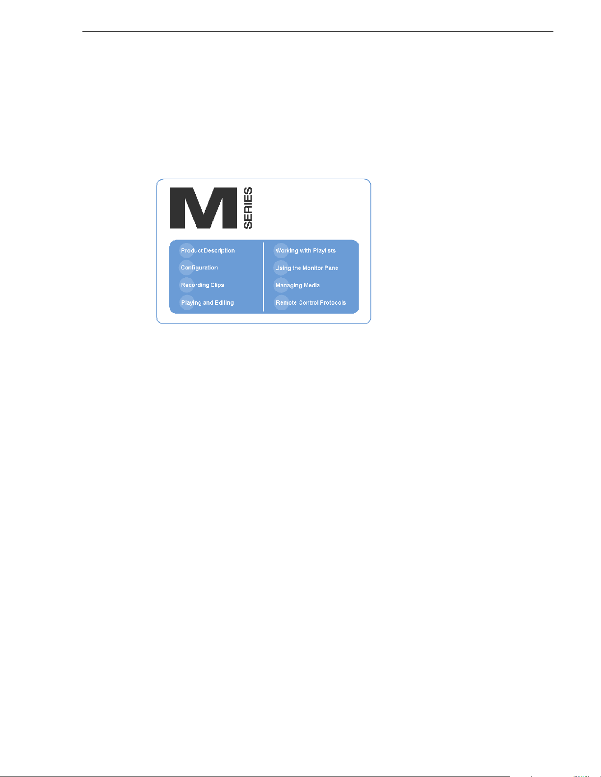
How this manual is organized
This manual is organized around the tasks required to install, configure, and operate
the M-Series iVDR. The following describes the chapters included in this manual:
Chapter 1, Installing the M-Series iVDR — Describes how to make rear panel
connections and configure the iVDR for basic operation.
Chapter 2, Quick Start Procedures — Use these procedures to learn the basics the
iVDR user interface to accomplish key tasks— recording, playing, trimming, and
creating playlists.
Chapter 3, Product Descriptio n — Provides the product functional description and an
introduction to AppCenter, the main user interface.
Chapter 4, Modifying Configuration — Describes how to modify the M-Series iVDR
configuration settings using the Configuration dialog box.
Chapter 5, Using the Monitor Pane — Provides information for using the Monitor
pane and for customizing it to suit your workflow.
Chapter 6, Recording Clips — Describes how to use the Recorder application to
record clips.
Chapter 7, Playing and Editing — Describes how to use the Player application to play
clips, trim clips, and create subclips.
Chapter 8, Working With Playlists — Describes how to use the PlayList application
to create and manage playlists.
Chapter 9, Managing Media Using Clips Pane — This chapter describes how to use
the Clips pane to manage media. Learn how t o move, delete, copy , i mport/export
assets, and to create an d manage bins (direct ories) to organize medi a.
Chapter 10, Usin g Rem ote Cont rol P rotocol s — Describes how to setup and industry
standard remote control protocols to control the M-Series iVDR.
Appendix A, Specifications — Describes the mechanical, environmental, and
electrical specifications of the iVDR.
Appendix B, Rack-mounting and Connector Pin-outs — Contains step-by-step
rack-mount procedures and information about rear panel connector pin-outs.
20 April 2005 M-Series User Manual 11
Page 12
Finding Information
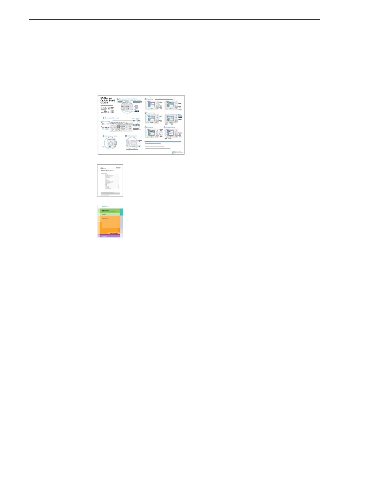
Other printed manuals
This manual is part of a full set of support documentation you received with your
M-Series iVDR.
M-Series iVDR Quick Start Guide — This
•
guide provides step-by-step installation
instructions for basic installation and
operation, including recording and playing
clips, trimming clips, and making a playlist.
M-Series iVDR Release Notes — C ontains the latest information about
•
the M-Series iVDR software shipped on your system. The
information in this document includes software upgrade instructions,
software specifications and requirements, feature changes from the
previous releases, and any known problems.
M-Series iVDR Service Manual — Contains information for solving
•
common setup problems, as well as information on servicing and
maintenance.
12 M-Series User Manual 20 April 2005
Page 13
Getting more information
In addition to the printed manuals, information is available in the following locations.
On-line Help
On-line help is available through the M-Series user interface.
Getting more information
To access online help:
• In the main user interface toolbar, select
pop-up menu. The M-Series Help home page is displayed.
- or -
• In any M-Series application or tool, select the context menu, then choose
Online help for the application is displayed.
Printed manuals in PDF format
All printed manuals are available in the Acrobat file format (pdf) on the M-Series
iVDR System Software CD-ROM. The manuals are located in the CD-ROM
Documentation directory.
Thomson Grass Valley Web site
This public Web site contains all the latest manuals and documentation, and
additional support information. Use the following URL.
http://www.thomsongrassvalley.com.
Tools, then choose Help from the
Help.
20 April 2005 M-Series User Manual 13
Page 14

Finding Information
Grass Valley Product Support
To get technical assistance, check on the status of problems, or report new problems,
contact Grass Valley Product Support vi a e-mail, the Web, or by phone or fax.
Web Technical Support
To acces s suppor t in format ion on the Web, v isit the p roduct supp ort We b page on t he
Grass Valley Web site. You can download software or find solutions to problems by
searching our Frequently Asked Questions (FAQ) database.
World Wide Web: http://www.thomsongrassvalley.com/support/
Technical Support E-mail Address: gvgtechsupport@thomson.net.
Phone Support
Use the following informatio n to contact product su pport by pho ne during business
hours. Afterhours phone support is available for warranty and contract customers.
United States (800) 547-8949 (Toll Free) France +33 (1) 34 20 77 77
Latin America (800) 547-8949 (Toll Free) Germany +49 6155 870 606
Eastern Europe +49 6155 870 606 Greece +33 (1) 34 20 77 77
Southern Europe +33 (1) 34 20 77 77 Hong Kong +852 2531 3058
Middle East +33 (1) 34 20 77 77 Italy +39 06 8720351
Australia +61 3 9721 3737 Netherlands +31 35 6238421
Belgium +32 2 3349031 Poland +49 6155 870 606
Brazil +55 11 5509 3440 Russia +49 6155 870 606
Canada (800) 547-8949 (Toll Free) Singapore +656379 1390
China +86 106615 9450 Spain + 34 91 512 03 50
Denmark +45 45968800 Sweden +46 87680705
Dubai + 971 4 299 64 40 Switzerland +41 (1) 487 80 02
Finland +35 9 68284600 UK +44 870 903 2022
Authorized Support Representative
A local authorized support representative may be available in your country. To locate
the support representative for your country, visit the product support Web page on the
Grass Valley Web site.
14 M-Series User Manual 20 April 2005
Page 15

Safety Summaries
General Safety Summary
Review the following safety precautions to avoid injury and prevent damage
to this product or any products connected to it.
Only qualified personnel should perform service procedures.
While using this product, you may need to access other parts of the system.
Read the General Safety summary in other system manuals f or warnings an d
cautions related to operating the system.
Injury P r e caution s
Use Proper Power Cord
To avoid fire hazard, use only the power cord specified for this product.
Ground the Product
This product is grounded through the grounding conductor of the power
cord. To avoid electric shock, the grounding conductor must be connected
to earth ground. Before making connections to the input or output terminals
of the product, ensure that the product is properly grounded.
Do Not Operate Without Covers
To avoid electric shock or fire hazard, do not operate this product with
covers or pa nels rem oved.
Do Not operate in Wet/Damp Conditions
To avoid electric shock, do not operate this product in wet or damp
conditions.
Do Not Operate in an Explosive Atmosphere
To avoid injury or fire hazard, do not operate this product in an explosive
atmosphere.
Avoid Exposed Circuitry
To avoid injury, remove jewelry such as rings, watches, and other metallic
objects. D o not to uc h exp os e d con ne cti o ns and c ompon e nts wh en po we r is
present.
Product Dam age P recautions
Use Proper Power Source
Do not operate this product from a power source that applies more than the
voltage specified.
Provide Proper Ventilation
To prevent product overheating, provide proper ventilation.
20 April 2005 M-Series User Manual 15
Page 16

Safety Summ ar ies
Do Not Operate With Suspected Failures
If you suspect there is damage to this product, have it inspected by qualified
service personnel.
Battery Replacement
To avoid damage, replace only with the same or equivalent type. Dispose of
used battery according to the circuit board manufacturer’s instructions.
Safety Terms and Symbols
Terms in This Manual
These terms may appear in this manual:
!
!
Terms on the Product
Symbols on the Product
WARNING: Warning statements identify conditions or practices that can
result in personal injury or loss of life.
CAUTION: Caution statements identify conditions or practices that may
result in damage to equipment or other property, or which may cause
equipment crucial to your business environment to become temporarily
non-operational.
These terms may appear on the product:
DANGER indicates a personal injury hazard immediately accessible as one
reads the marking.
WARNING indicates a personal injury hazard not immediately accessible
as you read the marking.
CAUTION indicates a hazard to property including the product.
The following symbols may appear on the product:
DANGER high voltage
Protective ground (earth) terminal
!
16 M-Series User Manual 20 April 2005
ATTENTION – refer to manual
Page 17

Service Safety Summary
!
Do Not Service Alone
Disconnect Power
Use Care When Servicing With Power On
WARNING: The service instructions in this manual are intended for
use by qualified service personnel only. To avoid personal injury, do
not perform any servicing unless you are qualified to do so. Refer to all
safety summaries before performi ng service.
Do not perform internal service or adjustment of this product unless another
person capable of rendering first aid and resusci tation is present.
To avoid electric shock, disconnect the main power by means of the power
cord or, if provided, the power switch.
Dangerous voltages or currents may exist in this product. Disconnect power
and remove battery (if applicable) be fore rem oving prot ective panels,
soldering, or replacing components.
To avoid electric shock, do not touch exposed connec tions
Certifications and Compli ances
Canadian Certified Power Cords
Canadian approval includes the products and power cords appropriate for
use in the North Amer ica power ne twork. All other powe r cords supp lied are
approved for the country of use.
FCC Emission Control
This equipment has been tested and found to comply with the limits for a
Class A digital device, pursuant to Part 15 of the FCC Rules. These limits
are designed to provide reasonable protection against harmful interference
when the equipment is operated in a commercial environment. This
equipment generates, uses, and can radiate radio frequency energy and, if
not installed and used in accordance with the instruction manual, may cause
harmful interference to radio communications. Operation of this equipment
in a residential area is likely to cause harmful interference in which case the
user will be required to correct the interference at his own expense. Changes
or modifications not expressly approved by Grass Valley can affect
emission compliance and could void the user’s authority to operate this
equipment.
20 April 2005 M-Series User Manual 17
Page 18

Safety Summ ar ies
Canadian EMC Notice of Compliance
EN55103 1/2
Class A Warning
FCC Emission Limits
This digital apparatus does not exceed the Class A limits for radio noise
emissions from digital apparatus set out in the Radio Interference
Regulations of the Canadian Department of Communications.
Le présent appareil numérique n’émet pas de bruits radioélectriques
dépassant les limites applicables aux appareils numériques de la classe A
préscrites dans le Règlement sur le brouillage radioélectrique édicté par le
ministèr e des Commun i cations du Canada.
This product has been evaluated for Electromagnetic Compatibility under
the EN 55103-1/2 standards for Emissions and Immunity and meets the
requirements for E4 environment.
This product complies with Class A (E4 environment). In a domestic
environment this product may cause radio interference in which case the
user may be required to take adequate measures.
This device complies with Part 15 of the FCC Rules. Operation is subject to
the following two conditions: (1) This device may not cause harmful
interference, and (2) this device must accept any interference received,
including interference that may cause undesirable operation.
Laser Compliance
Laser Safety Requirements
The device used in this product is a Class 1 certified laser p roduct. Operating
this product outside specifications or altering its original d esign m ay result
in hazardous radiation exposure, and may be considered an act of modifying
or new m anufactur ing of a laser product under U.S. regu lation s conta ined in
21CFR Chapter 1, subchapter J or CENELEC regulations in HD 482 S1.
People performing such an act are required by law to recertify and reidentify
this product in accordance with provisions of 21CFR subchapter J for
distribution within the U.S.A., and in accordance with CENELEC HD 482
S1 for distribution within countries using the IEC 825 standard.
Laser Safety
Laser safety in the United States is regulated by the Center for Devices and
Radiological Health (CDRH). The laser safety regulations are published in
the “Laser Product Performance Standard,” Code of Federal Regulation
(CFR), Title 21, Subchapter J.
The International Electrotechnical Commission (IEC) Standard 825,
“Radiation of Laser Products, Equipment Classification, Requirements and
User’s Guide,” governs laser products outside the United States. Europe and
member nations of the European Free Trade Association fall under the
jurisdiction of the Comité Européen de Normalization Electrotechnique
(CENELEC).
18 M-Series User Manual 20 April 2005
Page 19

Safety Certification
This product has been evaluated and meets the following Safety
Certification Standards:
Standard Designed/tested for complian ce with:
ANSI/UL60950, CAN/CSA
C22.2 No. 60950-00
12/01/2000
IEC 950 Safety of Information Technology Equipment, including
EN60950 Safety of Information Technology Equipment, including
Safety of Information Technology Equipment, including
Electrical Business Equipment (Third edition).
Electrical Business Equipment (Third edition, 1999).
Electrical Business Equipment (Third Edition 2000).
20 April 2005 M-Series User Manual 19
Page 20

Safety Summ ar ies
20 M-Series User Manual 20 April 2005
Page 21

Chapter
1
Installing the M-Series iVDR
Procedures in this chapter include:
• “Making connections for basic operation”
• “VGA Display ‘hot-key’ sequence”
• “Powering on and shutting down”
• “Configuring for basic ope ration”
• “Verifying basic operation”
• “Setting up the Ethernet network”
• “Conn ec ting IEEE 1394A”
• “Connecting RS422”
• “Connecting GPI”
20 April 2005 M-Series User Manual 21
Page 22
Chapter 1 Installing the M-Series iVD R
Making connections for basic operation
Connect as shown for recording and playing under local control. Refer to sections
later in this chapter for other connections, such as those for networking and remote
operation.
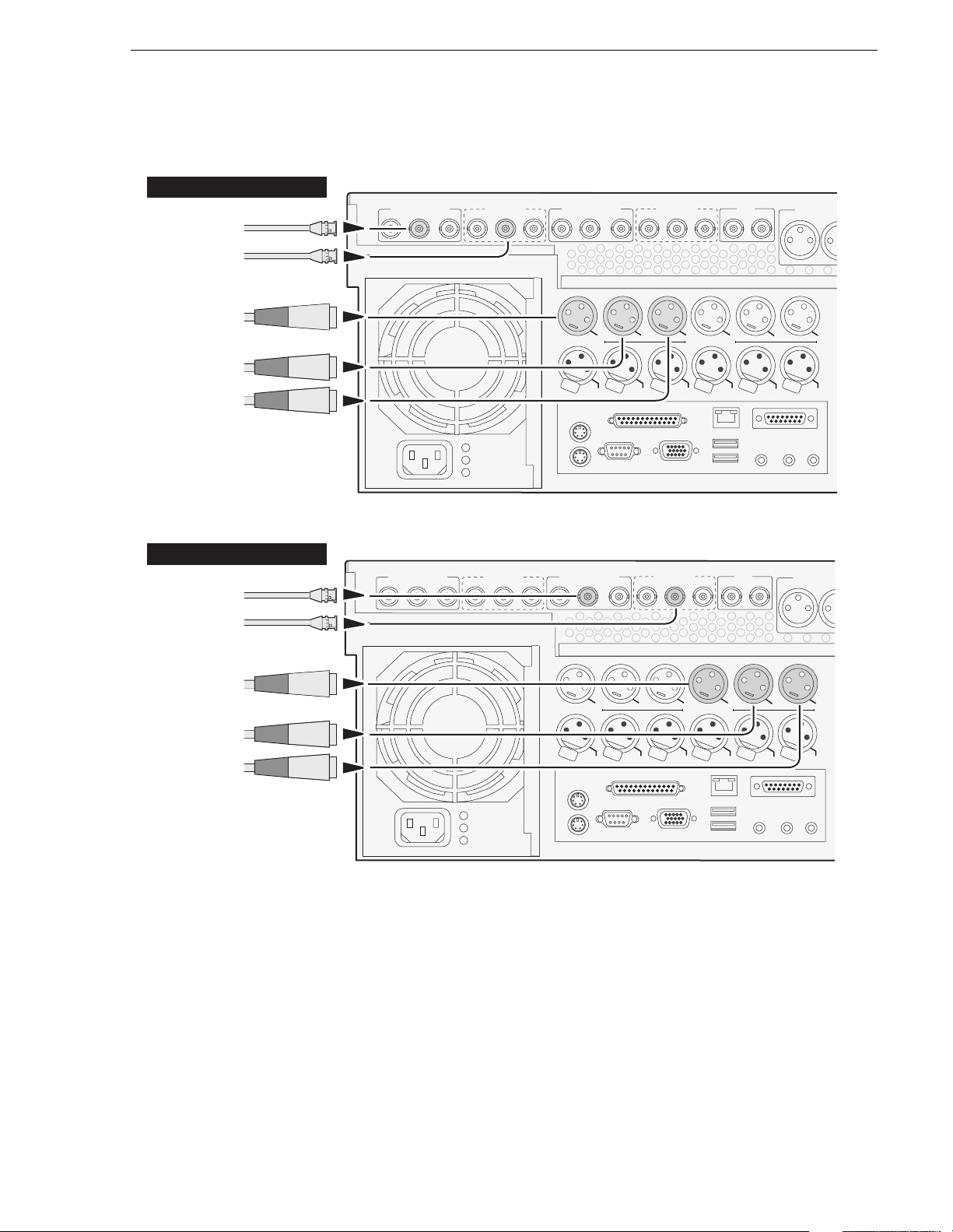
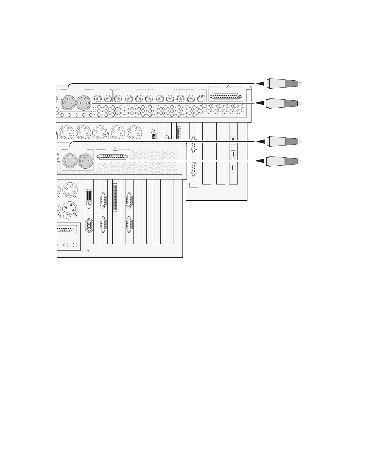
M-122A/M-222A: Record er inp ut con ne ctions
Recorder 1 Inputs (R1)
Video
SDI
R1 IN P1 OUT P1 OUT
Composite
Timecode
Analog audio
Channel 1 (L)
Composite R1 & P1
SDI R1 & P1
R1 IN P1 OUT P1 OUT
Composite R2 & P2
R2 IN P2 OUT P2 OUT
P1 LTC
h
s
u
P
R1 LTC
R2 IN
P1 CH1
Analog
Audio
h
s
u
P
R1 CH1
SDI R2 & P2
P2 OUT
P2 OUT
P1 CH2
h
s
u
P
R1 CH2
REF
Cmpst
P2 LTC
h
s
u
P
R2 LTC
Loop Thru
P2 CH1
Analog
Audio
h
s
u
P
R2 CH1
Audio MON O
L
P2 CH2
h
s
u
P
R2 CH2
OUT
IN
Channel 2 (R)
Recorder 2 Inputs (R2)
Video
SDI
Composite
Timecode
Analog audio
Channel 1 (L)
Channel 2 (R)
Composite R1 & P1
R1 IN P1 OUT P1 OUT
SDI R1 & P1
R1 IN P1 OUT P1 OUT
Composite R2 & P2
R2 IN P2 OUT P2 OUT
P1 LTC
h
s
u
P
R1 LTC
R2 IN
P1 CH1
Analog
Audio
h
s
u
P
R1 CH1
SDI R2 & P2
P2 OUT
P2 OUT
P1 CH2
h
s
u
P
R1 CH2
REF
Cmpst
P2 LTC
h
s
u
P
R2 LTC
Loop Thru
P2 CH1
Analog
Audio
h
s
u
P
R2 CH1
Audio MON O
L
P2 CH2
h
s
u
P
R2 CH2
OUT
IN
22 M-Series User Manual 20 April 2005
Page 23
M-122A/M-222A: Player output connections
M-122A/M-222A: Player ou tpu t conn ecti on s
Player 1 Outputs (P1)
Video
Composite
SDI
Composite R1 & P1
R1 IN P1 OUT P1 OUT
SDI R1 & P1
R1 IN P1 OUT P1 OUT
Composite R2 & P2
R2 IN P2 OUT P2 OUT
R2 IN
SDI R2 & P2
P2 OUT
P2 OUT
Cmpst
REF
Loop Thru
Audio MON O
L
Timecode
Analog audio
Channel 1 (L)
Channel 2 (R)
Player 2 Outputs (P2)
Video
Composite
SDI
Timecode
Analog audio
Channel 1 (L)
Channel 2 (R)
Composite R1 & P1
R1 IN P1 OUT P1 OUT
SDI R1 & P1
R1 IN P1 OUT P1 OUT
P1 LTC
h
s
u
P
R1 LTC
Composite R2 & P2
R2 IN P2 OUT P2 OUT
P1 LTC
h
s
u
P
R1 LTC
P1 CH1
h
s
u
P
R1 CH1
R2 IN
P1 CH1
Analog
Audio
h
s
u
P
R1 CH1
Analog
Audio
P1 CH2
h
s
u
P
R1 CH2
SDI R2 & P2
P2 OUT
P2 OUT
P1 CH2
h
s
u
P
R1 CH2
P2 LTC
h
s
u
P
R2 LTC
REF
Cmpst
P2 LTC
h
s
u
P
R2 LTC
P2 CH1
h
s
u
P
R2 CH1
Loop Thru
P2 CH1
Analog
Audio
h
s
u
P
R2 CH1
Analog
Audio
R2 CH2
P2 CH2
h
s
u
P
R2 CH2
Audio MON O
L
P2 CH2
h
s
u
P
OUT
IN
OUT
IN
20 April 2005 M-Series User Manual 23
Page 24
Chapter 1 Installing the M-Series iVD R
C
C
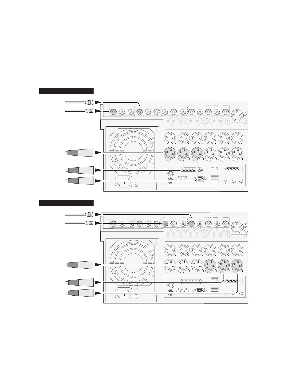
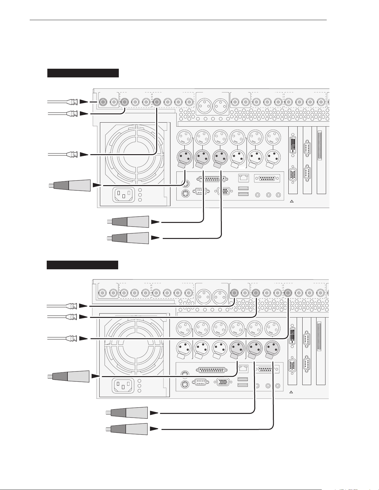
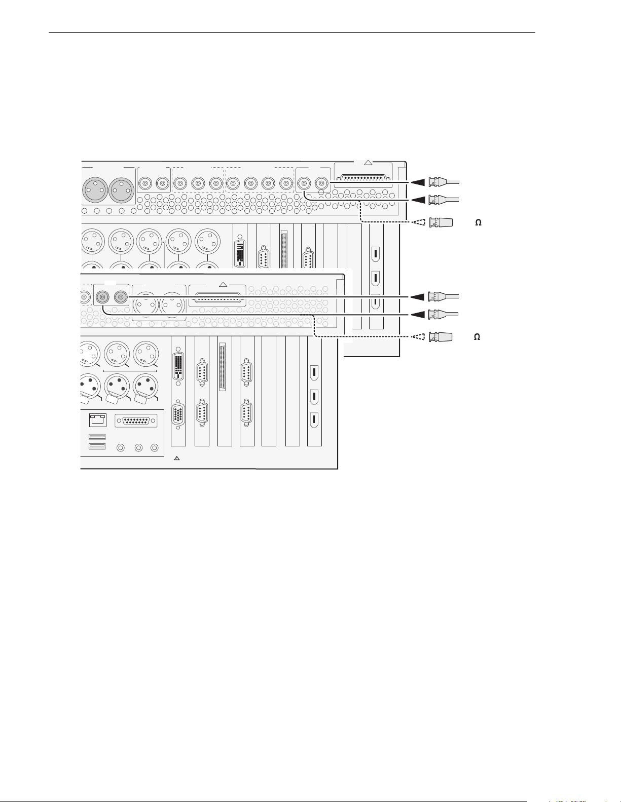
M-222D/M-322D: Record er inp ut con ne ctions
Recorder 1 Inputs (R1)
Video
Composite
SDI
Digital Audio
Timecode
CMPST R1 & P1
R1 IN R1 IN CH 1/2
P1 OUT
SDI R1 & P1
P1 OUT 1
P1 OUT 2
CH 1/2
R1 IN
AES/EBU R1 & P1
P1 OUT
P1 LTC
Push
R1 LTC
CH 3/4CH 3/4
AUD MON OUT
LR
P1 CH1
Analog
Audio
Push
R1 CH1
R2 IN R2 IN CH 1/2
P1 CH2
Push
R1 CH2
CMPST R2 & P2
P2 OUT
P2 LTC
Push
R2 LTC
SDI R2 & P2
P2 OUT 1 P2 OUT 2
P2 CH1
Analog
Audio
Push
R2 CH1
P2 CH2
Push
R2 CH2
OUT
IN
CH 1/2
R2 IN
FRONT
PANEL
VGA
AES/EBU R2 & P2
P2 OUT
RS422
PORT 1
PORT 2
CH 3/4CH 3/4
SCSI
Analog audio
Channel 1 (L)
Channel 2 (R)
Recorder 2 Inputs (R2)
CMPST R1 & P1
Video
R1 IN R1 IN CH 1/2
Composite
SDI
Digital Audio
Timecode
P1 OUT
SDI R1 & P1
P1 OUT 1
P1 OUT 2
CH 1/2
R1 IN
AES/EBU R1 & P1
P1 OUT
P1 LTC
Push
R1 LTC
CH 3/4CH 3/4
AUD MON OUT
LR
P1 CH1
Analog
Audio
Push
R1 CH1
R2 IN R2 IN CH 1/2
P1 CH2
Push
R1 CH2
CMPST R2 & P2
P2 OUT
P2 LTC
Push
R2 LTC
SDI R2 & P2
P2 OUT 1 P2 OUT 2
P2 CH1
Analog
Audio
Push
R2 CH1
P2 CH2
Push
R2 CH2
OUT
IN
CH 1/2
R2 IN
FRONT
PANEL
VGA
AES/EBU R2 & P2
RS422
PORT 1
PORT 2
P2 OUT
CH 3/4CH 3/4
SCSI
Analog audio
Channel 1 (L)
Channel 2 (R)
24 M-Series User Manual 20 April 2005
Page 25
M-222D/M-322D: Player output connections
C
C
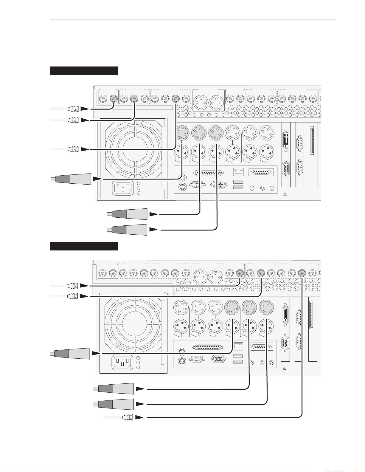
M-222D/M-322D: Player ou tpu t conn ecti on s
Player 1 Outputs (P1)
Video
R1 IN R1 IN CH 1/2
Composite
SDI
Digital Audio
Timecode
Analog audio
Channel 1 (L)
Channel 2 (R)
Player 2 Outputs (P2)
CMPST R1 & P1
P1 OUT
SDI R1 & P1
P1 OUT 1
P1 OUT 2
CH 1/2
R1 IN
AES/EBU R1 & P1
P1 OUT
P1 LTC
Push
R1 LTC
CH 3/4CH 3/4
AUD MON OUT
LR
P1 CH1
Analog
Audio
Push
R1 CH1
R2 IN R2 IN CH 1/2
P1 CH2
Push
R1 CH2
CMPST R2 & P2
P2 OUT
P2 LTC
Push
R2 LTC
SDI R2 & P2
P2 OUT 1 P2 OUT 2
P2 CH1
Analog
Audio
Push
R2 CH1
P2 CH2
Push
R2 CH2
OUT
IN
CH 1/2
R2 IN
FRONT
PANEL
VGA
AES/EBU R2 & P2
P2 OUT
RS422
PORT 1
PORT 2
CH 3/4CH 3/4
SCSI
Video
Composite
SDI
Timecode
Analog audio
Channel 1 (L)
Channel 2 (R)
Digital Audio
CMPST R1 & P1
R1 IN R1 IN CH 1/2
P1 OUT
SDI R1 & P1
P1 OUT 1
P1 OUT 2
CH 1/2
R1 IN
AES/EBU R1 & P1
P1 OUT
P1 LTC
Push
R1 LTC
CH 3/4CH 3/4
AUD MON OUT
LR
P1 CH1
Analog
Audio
Push
R1 CH1
R2 IN R2 IN CH 1/2
P1 CH2
Push
R1 CH2
CMPST R2 & P2
P2 OUT
P2 LTC
Push
R2 LTC
SDI R2 & P2
P2 OUT 1 P2 OUT 2
P2 CH1
Analog
Audio
Push
R2 CH1
P2 CH2
Push
R2 CH2
OUT
IN
CH 1/2
R2 IN
FRONT
PANEL
VGA
AES/EBU R2 & P2
P2 OUT
RS422
PORT 1
PORT 2
CH 3/4CH 3/4
SCSI
20 April 2005 M-Series User Manual 25
Page 26
Chapter 1 Installing the M-Series iVD R
!
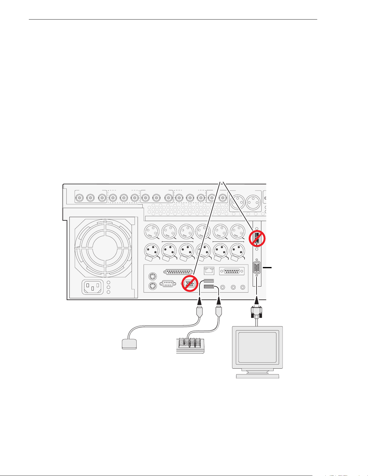
Keyboard, mouse, and VGA monitor connections
If your M-Series iVDR does not have the optional Front Panel, these connections are
required for local operation.
If your M-Series iVDR has the optional Front Panel, these connections are not
required. However, keyboard, mouse, and monitor provide an alternate means to
operate your M-Series iVDR. For example, if you need to enter extensive text or
number s equences you might find the keyboard easier to use. You may also want to
connect an external VGA display to monitor operations on a larger screen size,
however, you must first enable the VGA output. Refer to “Enabling the VGA monitor
output” on page 86.
NOTE: You can use the USB connectors provided along the edge of the optional
Front Panel to connect a keyboard or mouse.
Composite R1 & P1
R1 IN P1 OUT P1 OUT
SDI R1 & P1
R1 IN P1 OUT P1 OUT
R2 IN P2 OUT P2 OUT
Composite R2 & P2
R2 IN
SDI R2 & P2
P2 OUT
P2 OUT
Do not
connect
monitor
REF
Cmpst
Loop Thru
Audio MON Out
LR
h
s
USB mouse
(Supplied with iVDR)
P1 LTC
P1 CH1
Analog
Audio
h
s
u
u
P
P
R1 LTC
R1 CH1
USB keyboard
(Supplied with iVDR)
P1 CH2
h
s
u
P
R1 CH2
P2 LTC
h
s
u
P
R2 LTC
OUT
P2 CH1
P2 CH2
Analog
Audio
h
s
u
P
R2 CH1
h
s
u
P
R2 CH2
IN
VGA monitor
(Not supplied with iVDR)
If the Front Pa n el
option is installed,
refer to “Enabling
the VGA m on itor
output” on page 86.
26 M-Series User Manual 20 April 2005
Page 27
Audio monito ri ng connections
!
!
Connect audio monitor as shown.
Audio monitoring connections
AUD MON OUT
LR
P1 CH1
Analog
Audio
Audio MON Out
ru
LR
Push
R1 CH1
OUT
P2 CH1
P2 CH2
Analog
Audio
CH1
h
s
u
P
R2 CH2
IN
GPIO
SDI R2 & P2
P2 OUT 1 P2 OUT 2
P2 CH1
Analog
Audio
Push
R2 CH1
SCSI
RS422
PORT 3
PORT 4
P2 CH2
Push
R2 CH2
OUT
IN
CH 1/2
R2 IN
FRONT
PANEL
VGA
CMPST R2 & P2
R2 IN R2 IN CH 1/2
P2 OUT
P2 LTC
P1 CH2
Push
Push
R1 CH2
R2 LTC
FRONT
RS422
PANEL
PORT 1
PORT 2
VGA
M-122A/M222A
AES/EBU R2 & P2
P2 OUT
RS422
PORT 1
PORT 2
CH 3/4CH 3/4
SCSI
REF
COMPOSITE LOOP
THRU
RS422
PORT 3
PORT 4
GPI
1394
M-222D/M322D
Left
(Ch1)
Right
(Ch2)
Left
(Ch1)
Right
(Ch2)
20 April 2005 M-Series User Manual 27
Page 28
Chapter 1 Installing the M-Series iVD R
!
h
!
Reference Video conn ecti on s
Connect a reference video signal as shown. The reference signal must be an analog
composite signal. You must terminate the signal if you are not connecting the
loop-through to another device.
AUD MON OUT
LR
P1 CH1
Analog
Audio
REF
Push
OUT
Cmpst
Loop Thru
R1 CH1
P2 LTC
s
u
P
R2 LTC
P2 CH1
h
s
u
P
R2 CH1
OUT
IN
SDI R2 & P2
P2 OUT 1 P2 OUT 2
P2 CH1
Analog
Audio
Push
R2 CH1
FRONT
PANEL
VGA
RS422
PORT 1
PORT 2
P2 CH2
GPIO
Push
R2 CH2
OUT
IN
SCSI
CH 1/2
R2 IN
FRONT
PANEL
VGA
CMPST R2 & P2
R2 IN R2 IN CH 1/2
P2 OUT
P2 LTC
P1 CH2
Audio MON Out
Push
Push
LR
R1 CH2
R2 LTC
P2 CH2
Analog
Audio
h
s
u
P
R2 CH2
AES/EBU R2 & P2
RS422
PORT 1
PORT 2
RS422
PORT 3
PORT 4
SCSI
REF
COMPOSITE LOOP
THRU
RS422
PORT 3
PORT 4
1394
P2 OUT
CH 3/4CH 3/4
M-122A/M-222A
GPI
1394
M-222D/M322D
Reference in/out
Reference in/out
-OR-
75 terminator
Reference in/out
Reference in/out
-OR75 terminator
28 M-Series User Manual 20 April 2005
Page 29
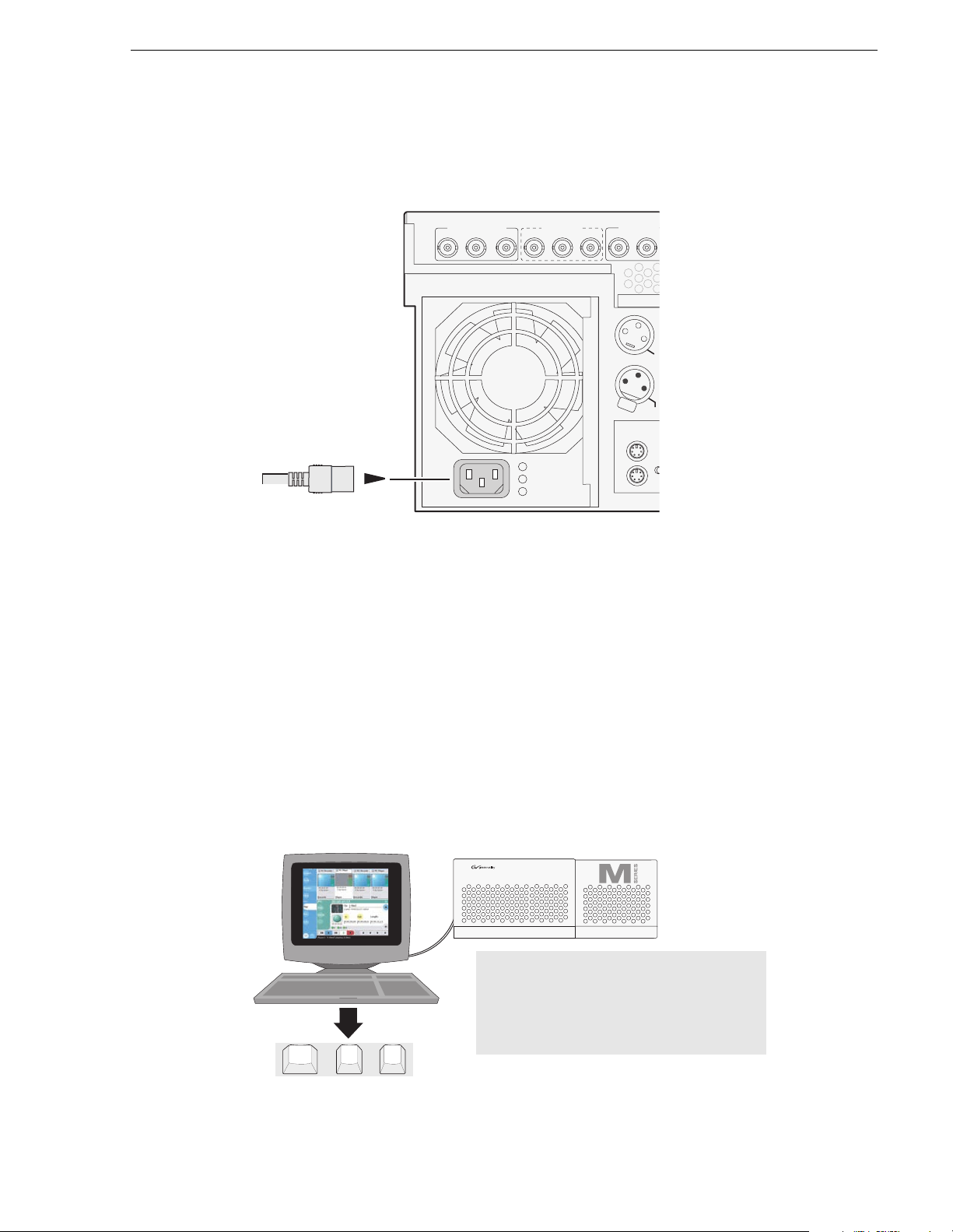
Power connection
T
C
R
Connect the power cable as shown.
Power connection
Composite R1 & P1
R1 IN P1 OUT P1 OUT
SDI R1 & P1
R1 IN P1 OUT P1 OUT
VGA Display ‘hot-key’ sequence
On systems without the optional Front Panel installed, the Windows desktop is
oversized at power-up and scrolls as you move the mouse. This is because the display
adapter card in the iVDR always starts in 640x480 mode even though the Windows
screen si ze is set to 800x 60 0.
Composite
R2 IN P2 OUT
P1 L
h
s
u
P
R1 LT
To easily change the display adapter settings, press the
CTRL+ALT+C hot-key
sequence when AppCenter is fully initialized after power-up to switch the display
adapter card to 800x600 display settings. If you inadvertently select this key sequence
on an iVDR with a front panel, press the
CTRL+ALT+L hot-key sequence to return to
640x480 display settings which is required for front panel operation.
P1
R1
P2
R2
SHTL
JOG
IMPORTANT: On systems without the
optional fr ont panel, pr ess the Ctrl +Alt+C
hot-key sequence when AppCenter is
fully initialized after power-up to set the
correct display settings.
Alt
Ctrl
+
C
+
20 April 2005 M-Series User Manual 29
VAR
Page 30
Chapter 1 Installing the M-Series iVD R
Powering on and shutting down
The following sections provide procedures for power on and shutdown.
To power on
Unlatch and
1
lower the drive
bay door.
Push the standby switch.
2
Wait for the Windows
operating system to
startup, then the iVDR
applications start
automatically.
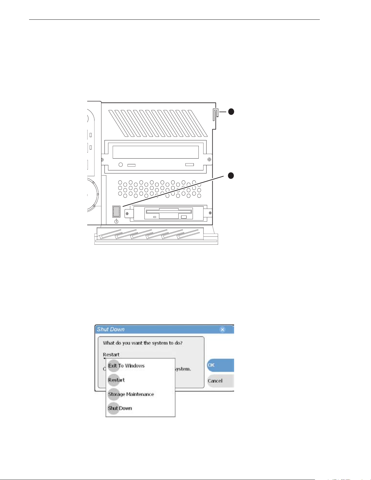
To shutdown or restart
1. In the AppC enter toolbar, selec t System, then choose Shutdown in the pop-up
menu.
The Shutdown dialog box appears.
2. In the Shutdown dialog box, choose a shutdown mode using the drop-down list,
then select
OK.
30 M-Series User Manual 20 April 2005
Page 31

To shutdown or restart
Dialog box shutdown modes:
Shutdown Mode Description
Exit to Windows Exit AppCenter and display the Windows desktop.
Use the desktop shortcut to restart AppCenter.
Restart Exit AppCenter and restart the Windows operating
system. AppCenter will restart automatically.
Storage Maintenance Mode Exit AppCenter and restart the iVDR in storage
maintenance mode to allow maintenance on the
media disk subsystem. Refer to the M-Series
Service Manual for procedures.
Shutdown Shutdown the Windows operating system and
power-off the iVDR.
NOTE: If you believe your iVDR is “hung” in an unresponsive state, you can
perform a forced shutdown by pressing and holding the standby but ton for
approximately five seconds.
!
WARNING: The power standby switch does not turn off power to the
system. The system must be disconnected from the power source.
20 April 2005 M-Series User Manual 31
Page 32

Chapter 1 Installing the M-Series iVD R
Accessing the Windows desktop
For some tasks, such as configuring for Ethernet networking, you must access the
Windows operating system. Use the following procedure to minimize AppC enter.
To access the Windows desktop do the following:
• In the Toolbar select
AppCenter minimizes and the Windows desktop appears.
To maximize, select the maximize button on the AppCenter title bar.
CAUTION: The M-Series is not a general purpose Windows
!
workstation. The Windows configuration on the iVDR has been
specifically set for use as a real time device. The M-Series iVDR is
configured for automatic logon allowing unattended booting. To avoid
partial or total system failure, do not modify any operating system
settings unless approved by Grass Valley, including but not limited to
the following:
— Do not use the User Manager
— Do not use the Disk Administrator
— Do not load any third party software
— Do not install any Windows updates other than “critical updates”
without contacting Grass Valley Product Support
System, then choose Minimize.
Configuring for basic operation
Use the following procedures to configure the iVDR for basic record and play
operations under local control.
For complete configuration procedures refer to Chapter 4, Modifying Configuration.
Configuration tasks:
• “Select system settings” on page 32
• “Select the video input” on page 34
• “Select the audio input (digital models only)” on page 35
• “Select timecode source” on page 36
Select system settings
1. On the Toolbar, select System and choose Configuration.
The Configuration dialog opens.
2. On the Configuration dialog select
The System configuration page appears. The settings on this tab apply system-wide
to all record and play channels.
System.
32 M-Series User Manual 20 April 2005
Page 33

Select system settings
3. Select the video standard for the iVDR.
The iVDR must be restarted for video standard changes to take effect. You’ll be
prompted to restart when you exit the Configuration di alog box.
4. Set the audio reference level for the iVDR.
5. Scroll down to locate the question “What is your channel compression type?”.
6. Select one of the following compression types:
• DV25 or DV50— When you make the se selections, no fu rther compression
settings are available or necessary. Select
OK to save this setting, and when
prompted, restart the iVDR. Restarting is required for the video compression
changes to take effect. NOTE: DV50 is available in model M-322D only.
20 April 2005 M-Series User Manual 33
Page 34

Chapter 1 Installing the M-Series iVD R
• MPEG I-frame — When you make this selection, additional settings are
available. Proceed to step 7 to complete the MPEG I-Frame settings.
NOTE: MPEG I-frame compression is not available in model M-122A.
7. Make sure
MPEG I-frame is selected as instructed previously and then scroll down
to display the additional MPEG settings.
8. Select Data Rate.
50Mb/s is available only in the M-Series model M-322D.
9. Select VBI settings.
Select the
Active picture plus VBI option if you need to record signals or data
inserted in the vertical blanking interval (VBI). Otherwise, you should select
picture only option. The VBI information is compressed along with the picture
content. You may need to increase the data rate if you have trouble with the
integrity of the VBI signals during playback.
10. Select
OK to save all changes at once.
11.When prompted, restart the iVDR. The restart is required to put the video
compression or video standard change into effect.
Select the video inpu t
To select the video input of each record channel:
1. Select
2. Select the
3. Locate the question “What is your video input type?”.
System and choose Configuration, then select the Channel button.
R1 or R2 tab, and open the Video Input link.
Close other links or use the scroll button if necessary to locate the link.
Active
34 M-Series User Manual 20 April 2005
Page 35

4. Make selections as follows:
Select the audio in p ut (digital model s only)
• Analog Composite — Make this selection to record analog composite video
connected to the record channel’s Composite input. If a warning message is
displayed about composite signal not present, verify that and composite signal
is connected. When you select Analog composite additional video input settings
are available as explained in “Record channel settings” on page 107.
• SDI Component — Make this selection to record SDI component video
connected to the record channel’s SDI input. If a warning message is displayed
about SDI not present, verify that and SDI signal is connected.
5. Select
OK to save changes, or proceed to “Select the audio input (digital models
only)”.
Select the audio input (d igital models onl y )
You must select the audio input on iVDR models equipped with digital audio inputs.
To select the audio input of each record channel:
1. Select
2. Select the
Close other links or use the scroll button if necessary to locate the link.
3. Locate the question “What is your audio input type?”.
System and choose Configuration, then select the Channel button.
R1 or R2 tab, and open the Audio Input link.
20 April 2005 M-Series User Manual 35
Page 36

Chapter 1 Installing the M-Series iVD R
4. Make selections as follows:
• Analog — records the analog audio connected to the record channel’s analog
audio input.
• AES — records the AES/EBU digital audio connected to the record channel’s
AES/EBU audio input.
• SDI Embedded — records the embedded audio signal on the Record channel’s
SDI input. When you select SDI Embedded, you must also select an embedded
audio group, 1 through 4, as shown in the diagram.
A warning message is displayed when no signal is detected for the audio input you
select.
NOTE: Audio is output simultaneously on all audio outputs. When using embedded
audio, you must ensure that the correct embedded audio group is selected for each
play channel. You can disable embedded audio output, if needed. See “Configuring
SDI output embedded audio” on page 120.
Select timecode source
The timecode source for each record channel is selected in the Recorder application
running on the channel. Refer to “Changing the timecode source” on page 152.
Verifying basic operation
Record and play a short clip to confirm that your connections and system setup are
correct.
Refer to the Chapter 2, Quick Start Procedures for record and play procedures.
36 M-Series User Manual 20 April 2005
Page 37

Setting up the Ethernet network
!
Refer to the following list of procedures, then perform the ones required to set up the
Ethernet network for your applicat ion.
• “Connecting the Ethernet network cabling”
Shows how to connect the iVDR to an Ethernet network using the standard
100BaseT port or the optional 1GBaseT port.
• “100BaseT Configurat i o n: Da t a an d st r e a ming between iVDRs” Contains
instructions for configuring the 100BaseT network connection to provide standard
data network capability and for streaming media transfers between iVDRs.
• “1GBaseT Configuration: Data and streaming between iVDRs” Contains
instructions for configuring the 1GBaseT network connection to provide standard
data network capability and for streaming media transfers between iVDRs.
• “Operating with both 100B T and 1GBT network conn ections”
Describes how to set up both networks so that you can use the low speed network
for standard da ta network ta sks, and the high sp eed network fo r streaming tra nsfers
between iVDRs.
• “100BaseT Configuration: iVDR and Profile XP streaming”. Follow these
instructions if you use the network for streaming media transfers to non-M-Series
devices such as the Profile XP Media Platform.
Setting up the Ethernet network
Connecting the Ethernet network cabling
Connect as illustrated. The high-speed (1 Gb) connection is available only if you have
the optional card installed.
P2 OUT
P2 LTC
2
h
s
u
P
Cmpst
R2 LTC
REF
Loop Thru
P2 CH1
h
s
u
R2 CH1
Audio MON Out
LR
P2 CH2
Analog
Audio
h
s
u
P
P
R2 CH2
OUT
IN
FRONT
PANEL
VGA
RS422
PORT 1
PORT 2
GPIO
RS422
PORT 3
PORT 4
SCSI
1000Bt
10Bt
100Bt
1000BT Network
(with optional card only)
10/100BT Network
20 April 2005 M-Series User Manual 37
Page 38

Chapter 1 Installing the M-Series iVD R
100BaseT Configur ation: Data and streaming between iVDRs
After making 100BaseT network connections as described in “Connecting the
Ethernet network cabling” on page 37, use the following procedure to configure the
network settings. Once configured, you can perform the following tasks:
• General networking tasks such as file sharing and mapping network drives.
• Remote control of the iVDR using devices and applications software developed for
the M-Series iVDR that use industry standard remote control protocols over
Ethernet.
• Streaming media transfers between iVDRs.
This procedure guides you to relevant settings, but does not instruct you on the
specific settings required for your network. It is assumed that you understand Ethernet
networks in general and your particular network needs and that you can apply that
understanding to make the required settings using standard Windows procedures. If
you need help with these procedures, contact your network administrator.
Procedure summary:
• “Configure Windows network settings” on page 38
• “Add network hosts names for streaming” on page 39
Configure Windows network settings
1. If you normally operate your M-Series iVDR using the optional Front Panel
touch-screen, you should connect keyboard and mouse before proceeding. Refer to
“Keyboard, mouse, and VGA monitor connections” on page 26 for instructions.
You will likely find it easier to configure your network using a keyboard and
mouse rather than the touch-screen. You may need to restart Windows to make the
mouse and keyboard operationa l.
2. Shut do wn A pp Cen t er a s fo ll ows :
a. In the AppCenter toolbar, select
menu.
The Shutdown dialog box appears.
b. Using the drop-down list, choose
AppCenter shuts down and the Windows desktop appears.
CAUTION: The M-S eries is not a general pur pose Windo ws workstat ion.
!
The Windows configuration on the iVDR has been specifically set for use
as a real time device. The M-Series iVDR is configured for automatic
logon allowing unattended booting. To avoid partial or total system
failure, do not modify any operating system settings unless approved by
Grass Valley, including but not limited to the following:
— Do not use the User Manager
— Do not use the Disk Administrator
— Do not load any third party software
— Do not install any Windows updates other than “critical updates”
without contacting Grass Valley Product Support
System, then choose Shutdown in the pop-up
Exit to Windows, then select OK.
38 M-Series User Manual 20 April 2005
Page 39

100BaseT Configu r ation: Data and streaming between iVD Rs
3. In the Windows taskbar, select Start | Settings | Network and Dial-u p Connecti ons
and conti nue w ith s tandar d Wind ows pr oced ures t o config ure the TCP /IP p rotoc ol
properties on each M-Series iVDR on the network. You can setup the network
using DHCP, DNS, WINS, or other st andard networkin g mechanisms.
NOTE: For a small network, without a DHCP server or domain name server
(DNS), you can set up a static IP address and create a Host file on each iVDR. The
Host file specifies a d ev ice nam e for ea ch IP a ddre ss use d on the ne twork . Ref er to
the Windows doc u mentation or your network administrator for more in formation.
4. Shutdown and restart Windows.
5. If you are going to stream video between iVDRs, proceed to “Add network hosts
names for streaming” on page 39, otherwise, the iVDR is ready for standard data
networking tasks.
Add network hosts names for streaming
You must add the ho st names of all peer iVDRs on the networ k that support str eaming
transfers. Adding host names is required to allow selection of networked iVDRs in the
AppCenter user interface and to provide a successful network connection for
streaming. The host names added will appear in the “Import” and “Send to” dialog
boxes.
NOTE: By default, the iVDR host name is the same as the Windows computer
name. To determine the iVDR computer name, right-click My Computer on the
Windows desktop, then properties. Select the Network Identification tab and look
for the “Full computer name”.
In addition, if you are using remote protocol to perform video network transfers,
you’ll need to assign a unique Controller ID number for each host name. If you are
not using r emote p rotoco l for net work t ransfers , you ca n leav e the Cont rolle r Id bla nk.
To add a netw or k host names :
1. Start AppCenter, if it is not already running, using the desktop shortcut.
2. In AppCenter toolbar, select
3. Select the
Hosts button.
System, then choose Configuration.
The networ k ho st na m es are dis pl a y ed.
20 April 2005 M-Series User Manual 39
Page 40

Chapter 1 Installing the M-Series iVD R
4. Select Add, to open the Add Host dialog box, then do the following:
a. Select the “Enter host name:” text entry control, then enter the computer name
of a peer iVDR.
Make sure to enter the exact computer name. Any differences will result in being
unable to connect to the iVDR.
b. If you a re u sing re mot e p ro toco ls t o per form vi de o ne tw ork t ra ns fers, yo u m us t
use the following steps to add a unique Controller ID for each host, otherwise,
you can ignore this step and proceed to step c.
- Select the “Enter controller ID:” text entry control.
- Enter the controller ID of the iVDR, then select
OK.
Make sure to enter a number between 1 and 255 that is unique to the iVDR.
c. Select
OK in the Add Host dialog box.
5. Repeat step 4 for the remaining iVDRs.
40 M-Series User Manual 20 April 2005
Page 41

100BaseT Configu r ation: Data and streaming between iVD Rs
6. In the Co nfiguration dialog box, sele ct OK to save settings.
Once the host names are added, the iVDR is ready for streaming operation. Refer
to “Importing assets from another iVDR or Profile XP system” on page 260, and
“Sending assets to another machine” on page 265 for procedures on transferring
media.
NOTE: If you have trouble, try using the ping utility in the Windows command
prompt using either the IP address or h ost name. Troubleshoot as needed. Also,
refer to the M-Series Service Manual for troubleshooting procedures.
20 April 2005 M-Series User Manual 41
Page 42

Chapter 1 Installing the M-Series iVD R
1GBaseT Configur atio n: Data an d streaming between iVDRs
After making 1GBaseT network connections as described in “Connecting the
Ethernet network cabling” on page 37, use the following procedure to configure the
network settings.
Once the 1GBaseT network configured, you can perform the following tasks:
• General networking tasks such as file sharing or importing/exporting from
networked devices using standard media file formats (AVI DV25/GXF).
• Remote control of the iVDR using devices and applications software developed for
the M-Series iVDR that use industry standard remote control protocols over
Ethernet.
• Stream media transfers between iVDRs using the General Exchange Format (GXF)
as described in SMPTE 360M. GXF streaming transfers allow loading and playing
a clip before the transfer is complete.
Setting up the 1GBaseT network for streaming transfer support has the following
network requirements:
• No DHCP and WINS, DNS, etc. Do not use automatic mechanisms for network
settings. Static IP addresses must be used on the iVDRs. All name resolution
must be through hosts files located on each networked device.
• The host name of all peer iVDRs must be added to a host registry using the
iVDR Configuration tool.
Procedure summary:
• “Set the static IP address”
• “Set up hosts files”
• “Add network hosts names for streaming”
Set the static IP address
This procedure guides you to relevant settings. It is assumed that you understand
Ethernet networks in general and your specific network needs and that you can apply
that understanding to make the settings required for a streaming network using
standard Windows procedures. If you need help with these procedures, contact your
networ k administrator.
To set up the static IP address on the 1GBaseT adapter:
1. If you normally operate your M-Series iVDR using the optional Front Panel
touch-screen, you should connect keyboard and mouse before proceeding. Refer to
“Keyboard, mouse, and VGA monitor connections” on page 26 for instructions.
You will likely find it easier to configure your network using a keyboard and
mouse rather than the touch-screen. You may need to restart Windows to make the
mouse and keyboard operationa l.
2. Shut do wn A pp Cen t er a s fo ll ows :
a. In the AppCenter toolbar, select
System, then choose Shutdown in the pop-up
menu.
The Shutdown dialog box appears.
42 M-Series User Manual 20 April 2005
Page 43

1GBaseT Configuration: Data and streaming between iVDRs
b. Using the drop-down list, choose Exit to Windows, then select OK.
AppCente r shuts down and the Wind ows desktop appears.
CAUTION: The M-Series is not a genera l purpose Wi ndows worksta tion.
!
The Windows configuration on the iVDR has been specifically set for use
as a real time device. The M-Series iVDR is configured for automatic
logon allowing unattended booting. To avoid partial or total system
failure, do not modify any operating system settings unless approved by
Grass Valley, including but not limited to the following:
— Do not use the User Manager
— Do not use the Disk Administrator
— Do not load any third party software
— Do not install any Windows updates other than “critical updates”
without contacting Grass Valley Product Support
Set up
3. In the Windows taskbar, select
Start | Settings | Network and Dial-up Connections
and continue with standard Windows procedures to set up the M-Series iVDR
static IP address.
Be sure to select the optional 1GBaseT adapter, not the standard 100BaseT adapter.
hosts
files
Name resolution for the 1GBaseT adapter cannot be set to DNS or WINS. You must
set up a hosts file located in c:\winnt\system32\drivers\etc\hosts on each iVDR. If you
include the names and addresses of all the iVDRs on the network, then you can create
one file and copy it to all the machines instead of editing the hosts file on each
machine.
On each iVDR, set up the hosts files as follows:
1. Open the following file using Notepad, or so me other text editor.
c:\winnt\system32\drivers\etc\hosts
2. Enter text in a single line for each iVDR, including the local iVDR.
The text format is simple. First type the IP address, then use the TAB key or Space
bar to insert a few spaces. Now type the machine name, such as
iVDR-1 followed
by the characters _he0 to specify network type as 1GBT. Be sure to use the zero
character, not the letter ‘o’.
NOTE: By default, the iVDR host name is the same as the Windows computer
name. To determine the iVDR computer name, right-click My Computer on the
Windows desktop, then properties. Select the Network Identification tab and look
for the “Full computer name”.
Example host file for three iVDRs on a 1Gb Ethernet network:
192.168.99.11 iVDR-1_he0
192.168.99.12 iVDR-2_he0
192.168.99.13 iVDR-3_he0
As an example, the following shows the content of a default Windows hosts file
with the new lines added. All lines beginning with a # are comments and can be
ignored or deleted.
20 April 2005 M-Series User Manual 43
Page 44

Chapter 1 Installing the M-Series iVD R
# Copyright (c) 1993-1995 Microsoft Corp.
#
# This is a sample HOSTS file used by Microsoft TCP/IP for Windows.
#
# This file contain s the mappings of IP addresses to host names. E ach
# entry shou ld be kept on an individual line. The IP address should
# be placed in the first column followed by the corresponding host name.
# The IP address and the host name should be separated by at least one
# space.
# Additionally, comments (such as these) may be inserted on individual
# lines or following the machine name denoted by a '#' symbol.
#
# For example:
#
# 102.54.94.97 rhino.acme.com # source server
# 38.25.63.10 x.acme.com # x client host
127.0.0.1 localhost
192.168.99.11 iVDR-1_he0
192.168.99.12 iVDR-2_he0
192.168.99.13 iVDR-3_he0
3. Save the file and exit the text editor.
4. Reboot your machine.
5. Copy the new hosts file onto all the other machine to save you editing it again.
6. Proceed to “Add network hosts names for st reaming”.
Add network hosts names for streaming
You must add the host names of all peer iVDRs on the network that support streaming
transfers. Adding host names is required to allow selection of networked iVDRs in the
AppCenter user interface and to provide a successful network connection for
streaming. The host names added will appear in the “Import” and “Send to” dialog
boxes.
NOTE: By default, the iVDR host name is the same as the Windows computer
name. To determine the iVDR computer name, right-click My Computer on the
Windows desktop, then properties. Select the Network Identification tab and look
for the “Full computer name”.
In addition, if you are using remote protocol to perform video network transfers,
you’ll need to assign a unique Controller ID number for each host name. If you are
not using remote protocol for network transfers, you can leave the Controller Id blank.
44 M-Series User Manual 20 April 2005
Page 45

1GBaseT Configuration: Data and streaming between iVDRs
To add a netw or k host names :
1. Start AppCenter, if it is not already running, using the desktop shortcut.
2. In AppCenter toolbar, select
3. Select the
Hosts button.
System, then choose Configuration.
The networ k ho st na m es are dis pl a y ed.
4. Select
Add, to open the Add Host dialog box, then do the following:
a. Select the “Enter host name:” text entry control, then enter the computer name
of a peer iVDR.
Make sure to enter the exact computer name. Any differences will result in being
unable to connect to the iVDR.
b. If you are u sin g r emo te prot oc ols to pe rf orm v ide o netw ork tra nsf ers, y ou mu st
use the following steps to add a unique Controller ID for each host, otherwise,
20 April 2005 M-Series User Manual 45
Page 46

Chapter 1 Installing the M-Series iVD R
you can ignore this step and proceed to step c.
- Select the “Enter controller ID:” text entry control.
- Enter the controller ID of the iVDR, then select
OK.
Make sure to enter a number between 1 and 255 that is unique to the iVDR.
c. Select
OK in the Add Host dialog box.
5. Repeat step 4 for the remaining iVDRs.
6. In the Configuration dialog box, select
OK to save settings.
Once the host names are added, the iVDR is ready for streaming operation. Refer
to “Importing assets from a nother iVDR or Profil e XP system” on page 260, and
“Sending assets to another machine” on page 265 for procedures on transferring
media.
NOTE: If you have trouble, try using the ping utility in the Windows command
prompt using either the IP address or host name. Troubleshoot as needed. Also,
refer to the M-Series Service Manual for troubleshooting procedures.
Operating with both 100 BT and 1GBT network con nection s
If you want to use both the 100BaseT and the 1GBaseT Ethernet connections, each
adapter can be set up as described in “100BaseT Configuration: Data and streaming
between iVDRs” on page 38 and “1GBaseT Configuration: Data and streaming
between iVDRs” on page 42. The low speed adapter and high speed adapter are
configured independently, and each must have its own unique IP address and network
setup.
Dual network adapters can create parallel network paths. Parallel network paths occur
when the iVDR is networked with other devices with dual network adapters, and those
devices are connected to the same 100BaseT and 1GBaseT networks.
The following describes how the iVDR handles parallel network paths:
• Video networking – When AppCenter request a streaming transfer, the iVDR will
automatically select the highest speed adapter, the 1GBaseT adapter, for streaming.
• Windows networking – If parallel paths exist between the iVDR and another
networked device, the 100BaseT adapter is used for standard windows networking
tasks, such as, file sharing and mapping network drives. This means if you are
using ‘Send to’ file or ‘Import from’ a file on a network drive, you will experience
transfer speeds typical for the 100BaseT network. However, you can reconfigure
the iVDR Windows network to use the 1GBaseT network adapter to connect to
network drives. Refer to the Windows documentation more information. Using the
1GBaseT network adapter will provide a faster connection to the mapped drive,
however, the extra network traffic could affect the bandwidth available for
streaming network transfers.
46 M-Series User Manual 20 April 2005
Page 47

100BaseT Configu r at ion : iV D R and P ro file XP stre am i ng
100BaseT Configuration: iVDR and Pr ofile XP streaming
The iVDR supports streaming transfers with other devices such as the Profile XP
Media Platform, or any device that supports the General Exchange Format (GXF) as
described in SM PTE 360M. The Prof ile XP sys tem mu st h ave t he opt ional 100B ase T
adapter installed and configured for streaming transfers.
The iVDR user interface does not support browsing a non-M-Series device, such as a
Profile XP Media Platform. In the Send To or Import user interface, you must select
the non-M-Series device, then specify the target manually by entering the disk volume
and bin nam e, e.g. EXT:\default. (Note that the target path is case sensitive.) In
addition, Me dia Manag er does not supp ort the iVDR whi ch means you ca nnot browse
media on the iVDR or initiate transfers from Media Manager running on the Profile
XP Media Platform. All transfers are initiated in the iVDR user interface.
Setting up the iVDR for streaming transfer with Profile XP Media Platforms has the
following network requirements:
• No DHCP and WINS, DNS, etc. Do not use automatic mechanisms for network
settings. Static IP addresses must be used on the iVDRs and Profile XP systems.
All name resolution must be through hosts files located on each networked
device.
• The host nam e of all peer iVDRs and Profile XP system s must be added to a host
registry using the iVDR Configuration tool.
Summary of net work setup tasks:
• “Make 100BaseT network connections”
• “Configure the iVDR static IP address”
• “Set up iVDR hosts f iles”
• “Add network hosts names for streaming”
• “Configure the Profile XP static IP address”
• “Test the network”
20 April 2005 M-Series User Manual 47
Page 48

Chapter 1 Installing the M-Series iVD R
Make 100BaseT network connections
Make 100BaseT network connections for both the iVDR and the Profile XP system
as shown in the following illustration. Refer to “Connecting the Ethernet network
cabling” on page 37 to locate iVDR rear panel network connectors. Refer to the
Profile XP System Guide to locate network connections on the Profile XP rear panel.
Ethernet
Switch
iVDR-1
R1
P2P1R2
SHTL
JOG
VAR
iVDR-2
R1
P2P1R2
SHTL
JOG
VAR
100BaseT
Network
Configure the iVDR static IP address
This procedure guides you to the relevant steps to configure a static IP address on the
iVDR. It is assumed that you understand Ethernet networks in general and that you
can apply that understanding to configure this network setting using standard
Windows tools. If you need help with these procedure s , contact your network
administrator.
To set up the static IP address on the 100BaseT adapter:
1. If you normally operate your M-Series iVDR using the optional Front Panel
touch-screen, you should connect keyboard and mouse before proceeding. You
will likel y find it easier to configure your network using a keyboard and mouse
rather than the touch-screen. Refer to “Keyboard, mouse, and VGA monitor
connections” on page 26. You may need to r estart Wind ows to make the mous e and
keyboard operational.
2. Shut do wn A pp Cen t er a s fo ll ows :
ProfileXP-1
Refer to the
Guide
Profile XP System
to make cable connections.
a. In the AppCenter toolbar, select
System, then choose Shutdown in the pop-up
menu.
The Shutdown dialog box appears.
b. Using the drop-down list, choose
Exit to Windows, then select OK.
AppCenter shuts down and the Windows desktop appears.
48 M-Series User Manual 20 April 2005
Page 49

100BaseT Configu r at ion : iV D R and P ro file XP stre am i ng
CAUTION: The M-Series is not a genera l purpose Windows
!
workstation. The Windows configuration on the iVDR has been
specifically set for use as a real time device. The M-Series iVDR is
configured for automatic logon allowing unattended booting. To avoid
partial or total system failure, do not modify any operating system
settings unless approved by Grass Valley, including but not limited to
the following:
— Do not use the User Manager
— Do not use the Disk Administrator
— Do not load any third party software
— Do not install any Windows updates other than “critical updates”
without contacting Grass Valley Product Support
Set up
3. In the Windows taskbar, select
Start | Settings | Network and Dial-up Connections
and continue with standard Windows procedures to set up the static IP address for
the M-Series iVDR 100BaseT adapter.
After setting the iVDR static IP address, proceed to the next procedure, “Set up
iVDR hosts files”.
iVDR hosts
files
Name resolution for the 100BaseT adapter cannot be set to DNS or WINS. You must
set up a hosts file located in c:\winnt\system32\drivers\etc\hosts on each iVDR. If you
include the names and addresses of all the iVDRs on the network, then you can copy
the same file onto all these machines instead of editing the hosts file on each machine.
On each iVDR, set up the hosts files as follows:
1. Open the following file using Notepad or some other text editor.
c:\winnt\system32\drivers\etc\hosts
2. Enter text in a single line for each machine, including the local machine. Entering
the name of the local machine allows you to copy and use the same file on all
iVDRs.
The text format is simple. First type the IP address, then use the TAB key or Space
bar to insert a few spaces. Now type the host name of each iVDR, for example
iVDR-1 and iVDR-2.
Example:
192.168.99.11 iVDR-1
192.168.99.12 iVDR-2
192.168.99.13 iVDR-3
NOTE: By default, the iVDR host name is the same as the Windows computer
name. To determine the iVDR computer name, right-click My Computer on the
Windows desktop, then properties. Select the Network Identification tab and look
for the “Full computer name”.
3. Enter the host name of each Profile XP Media Platform followed by the characters
_le0 to specify network type as 100BT. Be sure to use the zero character, not the
letter ‘o’. This is only required for the Profile XP systems.
Example host file for one Profile XP Media Platform and three iVDRs on a 100BT
20 April 2005 M-Series User Manual 49
Page 50

Chapter 1 Installing the M-Series iVD R
Etherne t ne t work:
192.168.99.11 iVDR-1
192.168.99.12 iVDR-2
192.168.99.13 iVDR-3
192.168.99.14 ProfileXP-1_le0
4. Add the IP add ress and host name of any o t her device on the video ne twork that
supports the General Exchange Format (GXF).
5. Save the file and exit the text editor.
6. Reboot the iVD R .
7. Copy the new hosts file onto all the other iVDRs and networked devices to save
you editing it again.
NOTE: It is not required to set up a host file on the Profile XP Media Platform since
all transfers are initiated from the iVDR. The Profile XP Media P latform does not
need to resolve host names.
After configuring the host file, proceed to the next procedure, “Add network hosts
names for streaming”.
Add network hosts names for streaming
You must add the host names of all peer iVDRs on the network that support streaming
transfers. Adding host names is required to allow selection of networked iVDRs in the
AppCenter user interface and to provide a successful network connection. The host
names added appear in the “Import” and “Send to” dialog boxes.
In addition, if you are using remote protocol to perform video network transfers,
you’ll need to assign a unique Controller ID number for each host name. If you are
not using remote protocol for network transfers, you can leave the Controller Id blank.
To add a network host name:
1. Start AppCenter, if it is not already running, using the desktop shortcut.
2. In AppCenter toolbar, select
3. Select the
Hosts button.
System, then choose Configuration.
The network host names are displayed.
50 M-Series User Manual 20 April 2005
Page 51

100BaseT Configu r at ion : iV D R and P ro file XP stre am i ng
4. Select Add, to open the Add Host dialog box, then do the following:
a. Select the “Enter host name:” text entry control, then enter the computer name
of a peer iVDR.
Make sure to enter the exact computer name. Any differences will result in being
unable to connect to the iVDR.
b. If you are usi ng remote protocol t o perform video network transfers, you must
use the following steps to add a unique Controller ID for each host, otherwise,
you can ignore this step and proceed to step c.
- Select the “Enter controller ID:” text entry control.
- Enter the controller ID of the iV DR or other networke d device, then select
OK.
Make sure to enter a number between 1 and 255 that is unique to the iVDR.
c. Select
20 April 2005 M-Series User Manual 51
OK in the Add Host dialog box.
Page 52

Chapter 1 Installing the M-Series iVD R
5. Repeat step 4 for the remaining iVDRs or other networked devices.
6. In the Configuration dialog box, select
7. Proceed to “Configure the Profile XP static IP address” on page 52.
Configure the Profile XP static IP address
Use standard Windows tools and procedures to configure the IP address on the
Profile XP Media Platform or oth er non-M-Series de vic e that support s General
Exchange Format (GXF) streaming transfers. You must use static IP address, and not
some automated method of setting IP address, such as DHCP.
Refer to the Profile XP System Guide or the appropriate manual for your
non-M-Series device to setup the network address.
After configuring the Profile XP IP address, proceed to the next procedure, “Test the
network”.
Test the network
Refer to “Importing assets from another iVDR or Profile XP system” on page 260,
and “Sending assets to another machine” on page 265 for procedures on transferring
media.
NOTE: If you have trouble, try using the ping utility in the Windows command
prompt using either the IP address or host name. Troubleshoot as needed. Also,
refer to the M-Series Service Manual for troubleshooting procedures.
OK to save settings.
52 M-Series User Manual 20 April 2005
Page 53

Connecting IEEE 1394A
u
!
!
The iVDR provides an optional IEEE 1394A interface for importing DV based video
and audio from a digital recording device. The iVDR record channel transport
controls can be used to control the remote device. The iVDR supports one 1394A
input. Refer to “Using IEEE 1394 Recor d mode” on page 148.
Connecti n g I EEE 1394A
REF
UT
Cmpst
P2 LTC
P
R2 LTC
Loop Thru
h
R2 CH1
Audio MON Out
LR
P2 CH1
P2 CH2
Analog
Audio
h
s
s
u
P
R2 CH2
OUT
IN
u
P
FRONT
PANEL
VGA
Connecting RS422
You can control the iVDR with remote control devices and software developed for the
iVDR that use industry-standard serial protocols. You can connect up to four RS422
cables to control iVDR channels depending on your remote control needs. Connect
the RS422 cabling as required, then refer to “Using Remote Control Protocols” on
page 277 to con figure the iVDR for remote control.
RS422
PORT 1
PORT 2
GPIO
1394A Input
(Optional)
RS422
PORT 3
PORT 4
SCSI
1394
Note:
The iVDR supports
one IEEE 1394 input.
ut
R
GPIO
Connect one or more
cables for remote
control devices
FRONT
PANEL
VGA
RS422
PORT 1
PORT 2
RS422
PORT 3
PORT 4
SCSI
20 April 2005 M-Series User Manual 53
Page 54

Chapter 1 Installing the M-Series iVD R
!
Connecting GPI
The iVDR provides 12 GPI inputs, and 12 GPI outputs on a singl e DB-25 rear pan el
connector.
RS422
PORT 1
PORT 2
GPIO
RS422
PORT 3
PORT 4
SCSI
ut
R
FRONT
PANEL
VGA
Also see the following related sections of this manual:
• “GPI I/O connector pinouts” on page 316
• “GPI I/O specifications” on page 305
• “Configuring GPI inputs /outputs” on page 121
• “Using GPI output triggers in playlists” on page 200
GPI in/out
54 M-Series User Manual 20 April 2005
Page 55

Chapter
2
Quick Start Procedures
Quick start procedures in this chapter include:
• “To record a clip”
• “To play a clip”
• “To trim a clip”
• “To create a playlist”
20 April 2005 M-Series User Manual 55
Page 56

Chapter 2 Quick Start Proc edures
To record a clip
If your system has no Front Panel, you must use a keyboard, mouse, and monitor
rather than the touch panel as illustrated. Alternate controls for keyboard, mouse, and
monitor are marked with an asterisk (*) and are provided on the VGA monitor only.
VAR
R1
R2
JOG
P1
P2
SHTL
Choose record
3
channel 1
or
1
R
Verify video source
4
Adjust audio
5
1
Display split-screen
view
Begin record
6
or
Select Monitor
2
Rename clip
8
P1
R1
P2
R2
SHTL
JOG
VAR
Stop record
7
*
or
*
Load and play the
9
clip as explained in
"To play a clip"
56 M-Series User Manual 20 April 2005
Page 57

To play a clip
If your system has no Front Panel, you must use a keyboard, mouse, and monitor
rather than the touch panel as illustrated. Alternate controls for keyboard, mouse, and
monitor are marked with an asterisk (*) and are provided on the VGA monitor only.
To play a clip
Select Clips
4
Choose a clip
5
P1
R1
P2
R2
6
or
(Rotate)
Load the clip
Press latch and
1
adjust front panel
viewing angle
2
Display split-screen view
VAR
3
R1
R2
JOG
SHTL
JOG
Choose play
channel 1
or
1
P
P1
P2
SHTL
(Push)
Select Monitor
7
8
Play the clip
or
or
*
VAR
Monitor audio
9
with headphones
20 April 2005 M-Series User Manual 57
Page 58

Chapter 2 Quick Start Proc edures
To trim a clip
If your system has no Front Panel, you must use a keyboard, mouse, and monitor
rather than the touch panel as illustrated. Alternate controls for keyboard, mouse, and
monitor are marked with an asterisk (*) and are provided on the VGA monitor only.
VAR
R1
R2
JOG
P1
P2
SHTL
1
Load a clip into
play channel 1
as explained in
"To play a clip"
2
Select Monitor
Locate a frame
3
or
Set in or out
4
mark to current
timecode
58 M-Series User Manual 20 April 2005
Page 59

To create a playlist
If your system has no Front Panel, you must use a keyboard, mouse, and monitor
rather than the touch panel as illustrated. Alternate controls for keyboard, mouse, and
monitor are marked with an asterisk (*) and are provided on the VGA monitor only.
VAR
R1
R2
JOG
SHTL
R1
R2
JOG
To create a playlist
Select Monitor
1
Choose channel P2
2
or
2
P1
P2
P1
P2
SHTL
P
Select
3
Playlist
on P2
Select Clips
4
Drag clips to list
5
Player
Playlist
Remote AMP
VAR
Play the list
6
or
*
20 April 2005 M-Series User Manual 59
Page 60

Chapter 2 Quick Start Proc edures
60 M-Series User Manual 20 April 2005
Page 61

Chapter
3
Product Description
Information in the chapter includes:
• “Product overview”
• “Determining storage capacity”
• “Front view with optional Front Panel”
• “Rear panel view”
• “Guid e to using AppCenter”
• “Using K eyboard shortcuts”
• “Guide to using the Front Panel”
• “Moni t oring the system using the StatusBa r”
• “Using the StatusPane”
• “Writing data to the CD-R/RW and DVD drives” on page 93
20 April 2005 M-Series User Manual 61
Page 62

Chapter 3 Product Descript io n
Product overview
The M-Series iVDR is a multi-channel video digital recorder that allows four
channels of simultaneous record and playback. Media is stored on internal disk drives.
Storage capacity depends on the disk option installed and the video compression
settings selected. See “Determining storage capacity” on page 66. The iVDR includes
a built in digital recorder application that handles essential tasks— record, edit, play,
and create/play event lists. The optional front panel includes an TFT display with
touch screen, and transport controls to allow easy operation and monitoring with
minimal external connections.
Key features
Simultaneous access to common storage – Simultaneous access to common storage
by all four channels means that you can play a clip that is still being recorded, and that
the a clip can be played simultaneously and independently on multiple channels.
Optional Fro n t Panel – The optional front panel features 640 by 480 TFT display
with touch screen and VTR-like transport controls. The front panel can be tilted to a
convenient operating angle, or removed and operated as a desktop device using an
optional 15 foot extension cable and cradle. The user interface provides an on-screen
keyboar d for text ent ry (enter ing names a nd timecod e), or you ca n connect a ke yboard
to the U SB port o n the fro nt panel . The keyboard also pr ovides for key board sh ortcuts
for transport control.
Integrated control applications software – The standard control application not
only enables a number of simple manual and semi-automatic operations previously
available with tape, but also takes advantage of the capabilities of a disk based
recorder, e.g. simultaneous record/play, list playout, clip trimming.
1. Features may change with new software releases. Be sure to consult the release notes for your software version.
62 M-Series User Manual 20 April 2005
1
Page 63

Key features
Multiple signal I/O formats – The following table describes the signal I/O formats
available in the iVDR. Refer to “Electrical specifications” on page 301 for complete
specifications.
Signal I/O format Description
Video
Analog Composite PAL/NTSC
SDI SDI conforms to SMPTE 259M
Audio
Analog Audio 2ch/video; Balanced differential analog; sampled @ 48 KHz; 16-bit pcm
AES/EBU Digital
Audio
Embedded Audio 4ch/video; user selectable audio group (1-4); Data format conforms to
Timecode
LTC 1ch per record channel; 1 ch per play channel
VITC Lines 10-22 (525 Line); Lines 6-23 (625 Line)
Internal Generator Time of day or user selectable start timecode; drop-frame or
IEEE 1394A Input
(Optional)
4 ch/video; Conforms to SMPTE 276M-1995
(Available in models M-222D/M-322D only.)
SMPTE 272M-1994
(Available in models M-222D/M-322D only.)
Reader: automatic detection or user selectable line numbers.
non-drop-frame.
IEEE 1394A; Available as a Record channel input for importing and
recording media from a digital recording device that uses DV format.
Selectable video compression formats – The following table describes the video
compression types available in the M-Series iVDR mo dels.
Model Compression Typ es
M-122A DV25
M-222A DV25
MPEG2 I fr a me onlya, up to 25Mb/s, 4:2:2
M-222D DV25
MPEG2 I fr a me onlya., up to 25Mb/s, 4:2:2
M-322D DV25
DV50
MPEG2 - I frame onlya., up to 50Mb/s, 4:2:2
MPEG D10 (Play only) - 4:2:2, 30, 40, 50 Mb/s (Input media by import or stream.)
a.
Selectable encode range includes active picture or active picture plus VBI.
Convenient monitoring – The front panel display includes on-screen video for
monitoring the selected channel. A front panel headphone jack and rear panel audio
monitor output are provided for audio monitoring. Both follow the front panel channel
selection.
20 April 2005 M-Series User Manual 63
Page 64

Chapter 3 Product Descript io n
Media t ran s fe r to ot her devices – The iVDR supports media transfers over the
standard Ethernet port or optional network adapters. Supported devices for media
transfers include other M-Series iVDRs, the Grass Valley Profile XP Media Platform,
or any device that supports SMPTE 360M streaming transfers. You must configure
the iVDR network settings prior to attempting media transfers.
Media file exchange using standard media file formats – You can exchange media
with other devices by importing and exporting files using standard file formats such
as AVI (D V) an d G ene ra l E xcha nge Fo r mat ( *. GX F) as de scr ibe d i n SM PT E 36 0M .
Files can be exchanged over a network connection or common forms of removable
media such as CD-RW, DVD-RW (optio nal).
Remote control support – You can use remote control devices and applications
software developed for t he M-Series iVDR t hat use industry -standard serial protocol s.
For each supported protocol, the iVDR provides a protocol-specific application.
Supported protocols includes VCDP or AMP protocols over RS422 or Ethernet.
GPI triggers – GPI input triggers can be assigned to channels to control actions such
as record, play, stop, and skip a playlist event. GPI output triggers can be defined for
channels and inserted in playlists to control external equipment as the list is played.
64 M-Series User Manual 20 April 2005
Page 65

Functional description
The diagram illustrates how the four iVDR channels operate independently, but share
a common internal disk storage area. This gives all channels, two record channels for
recording media and two play channels for playing media, simultaneous random
access to the same media files. This means that you can play a clip that is still
recording on one of the record channels. Each channel handles one video track, two
audio tracks, and one timecode track.
R1
Input
Circuit
R1
Record
Channel 1
Functional description
PB/EE Switch Path
P1
Output
Circuit
P1
Play
Channel 1
R2
Record
Channel 2
R2
Input
Circuit
P2
Play
Channel 2
P2
Output
Circuit
PB/EE Switch Path
Note that an E to E path is provided for monitoring purposes. When E to E mode is
enabled, the play channel video and audio outputs are switched to the corresponding
record channel inputs when the play channel is in stop mode or when no clip is loaded.
The following table describes play channel operation depending the E to E selection.
E to E Setting Play channel mode Play channel output
Disabled Play, FF, Rewind
Stop
Eject
Enabled Play, FF, Rewind
Stop
Eject
a.
Output is black if no video input is connected.
Show clip
Show clip
Show black
Show clip
Show input
Show input
a.
a.
20 April 2005 M-Series User Manual 65
Page 66

Chapter 3 Product Descript io n
E to E considerations
If E to E mode is enabled, you can connect an external reference signal which is
synchronous to the video input. This will eliminate artifacts on the play channel
output (periodic vertical shift) due to routing an asynchronous signal through the
iVDR. However, this is not required for recording, the iVDR can record asynchronous
signals.
NOTE: E to E is provided for monitoring the record channel, and is not intended
as a program switch.
Determining storage capacity
Internal media storage can be configured with three or six disk drives depending on
the storage option installed. A storage option adds three disk drives. Storage options
available include of 36GB, 73GB, and 146GB disk drives. These storage options can
be mixed, for example the iVDR can contain the three 36GB disk option with the three
146GB disk option.
The following tables show the storage capacity estimates based on the number of disk
drives installed and the video data rate. The estimates in the table are based on use of
four audio channels and one time code channel per video channel using the 525 video
format.
NOTE: Storage capacity will increase as larger disk sizes become available.
Storage capacity estimates in hours using 36 GB drives:
Video
Data Rate
18 Mbs 10 hrs 20 hrs
20 Mbs 9 hrs 18 hrs
25 Mbs 8 hrs 16 hrs
50 Mbs 4 hrs 8 hrs
a.
Calculated using 1 video track, 4
audio tracks, 1 timecode track,
and the 525 video standard.
Number of Drives
a
36
66 M-Series User Manual 20 April 2005
Page 67

Storage capacity estimates in hours using 73 GB drives:
Determining storage capacity
Video
Data Rate
Number of Drives
a
36
18 Mbs 22 hrs 44 hrs
20 Mbs 20 hrs 40 hrs
25 Mbs 16 hrs 32 hrs
50 Mbs 8 hrs 16 hrs
a.
Calculated using 1 video track, 4
audio tracks, 1 timecode track,
and the 525 video standard.
Storage capacity estimates in hours using 146 GB drives:
Video
Data Rate
Number of Drives
a
36
18 Mbs 43 hrs 86 hrs
20 Mbs 39 hrs 79 hrs
25 Mbs 32 hrs 65 hrs
50 Mbs 17 hrs 34 hrs
a.
Calculated using 1 video track, 4
audio tracks, 1 timecode track,
and the 525 video standard.
Storage capacity estimates in hours using 300 GB drives:
Video
Data Rate
Number of Drives
a
36
18 Mbs 86 hrs 173 hrs
20 Mbs 78 hrs 158 hrs
25 Mbs 65 hrs 130 hrs
50 Mbs 34 hrs 68 hrs
a.
Calculated using 1 video track, 4
audio tracks, 1 timecode track,
and the 525 video standard.
20 April 2005 M-Series User Manual 67
Page 68

Chapter 3 Product Descript io n
Front view with optional Front Panel
The following illustrations show the front view of the M-Series iVDR with the
optional Front Panel installed.
VAR
R1
R2
JOG
P1
P2
SHTL
Optional
Front Panel
VAR
R2
JOG
Drive Bay Door
CD-RW
Drive
Optional
DVD/RW
Push the latch to
lower the door.
Drive
P1
R1
P2
SHTL
Standby
Switch
Floppy
Drive
Drive Bay Door
Lowered and
In Open Position
68 M-Series User Manual 20 April 2005
Page 69

Rear panel view
!
!
M-122A/M222A
Composite R1 & P1
R1 IN P1 OUT P1 OUT
SDI R1 & P1
R1 IN P1 OUT P1 OUT
Composite R2 & P2
R2 IN P2 OUT P2 OUT
P1 LTC
Push
R1 LTC
R2 IN
P1 CH1
Push
R1 CH1
Analog
Audio
SDI R2 & P2
P2 OUT
P1 CH2
Push
R1 CH2
P2 OUT
REF
Cmpst
P2 LTC
Push
R2 LTC
Loop Thru
P2 CH1
Push
R2 CH1
Audio MON Out
LR
OUT
P2 CH2
Analog
Audio
Push
R2 CH2
IN
FRONT
PANEL
VGA
RS422
PORT 1
PORT 2
GPIO
Rear panel view
RS422
PORT 3
PORT 4
SCSI
M-222D/M322D
CMPST R1 & P1
R1 IN R1 IN CH 1/2
P1 OUT
SDI R1 & P1
P1 OUT 1
P1 OUT 2
CH 1/2
R1 IN
AES/EBU R1 & P1
P1 OUT
h
s
u
P1 LTC
P
R1 LTC
CH 3/4CH 3/4
AUD MON OUT
LR
P1 CH2
P1 CH1
Analog
Audio
h
h
s
s
u
u
P
P
R1 CH2
R1 CH1
CMPST R2 & P2
R2 IN R2 IN CH 1/2
P2 OUT
P2 LTC
h
s
u
P
R2 LTC
SDI R2 & P2
P2 OUT 1 P2 OUT 2
P2 CH1
Analog
Audio
h
s
u
P
R2 CH1
AES/EBU R2 & P2
R2 IN
CH 1/2
OUT
P2 CH2
IN
h
s
u
P
R2 CH2
FRONT
RS422
PANEL
PORT 1
PORT 2
VGA
P2 OUT
CH 3/4CH 3/4
SCSI
REF
COMPOSITE LOOP
THRU
RS422
PORT 3
PORT 4
GPI
20 April 2005 M-Series User Manual 69
Page 70

Chapter 3 Product Descript io n
Guide to using AppCenter
At power-up, the Windows operating system starts, automatically logs on, and then
automatically launches AppCenter, the main user interface. AppCenter is a built-in
video disk recorder application that provides a single interface for tasks such as:
configuration, clip management, media transfers, channel monitoring, system
monitoring, and record and playback control.
Starting AppCenter
There are two ways of restarting AppCenter.
• At power-up, the Windows operating system starts, automatically logs on using the
mseries user account (password = ms eries), and then automatically launches
AppCenter.
• Double-click the AppCenter shortcut on the Windows desktop.
70 M-Series User Manual 20 April 2005
Page 71

AppCenter control options
AppCenter control options
P1
R1
P2
R2
SHTL
JOG
VAR
Keyboard, Mouse
and Monitor
(Connect to Rear Panel)
Local Control
Keyboard, mouse, and monitor – Connecting a keyboard, monitor and mouse to the
iVDR rear panel provides access to AppCenter. You can use a mouse and keyboard
shortcuts to control the iVDR.
Front Pa nel – The optional Front Panel comes mounted on the front of the chassis,
however, it can be removed and operated remotely using an optional front panel
accessory kit which includes a 15 foot extension cable and front panel cradle. See
“Guide to using the Front Panel” on page 83. USB connectors on the edge of the Front
Panel allow you to connect a USB device, such as, a disk, memory stick, mouse,
keyboard, or transport control device. The keyboard is used f or text ent ry and
provides keyboard shortcuts to control the iVDR. A transport control device that
emulates a ke yboard can be used to c ontrol the iVDR throu gh keyboard shortcuts.
Remote Control
GPI I/O – GPI input triggers can be assigned to channels to control actions such as
record, play, stop, and skip a playlist event. GPI output triggers can be defined for
channels and inserted in playlists to control external equipment as the list is played.
See “Configuring GPI inputs/outputs” on page 121.
R1
P2P1R2
SHTL
JOG
VAR
Front Panel
(Mounted or Desktop)
GPI Control
Remote Control
Protocols
over RS-422
(BVW, AMP, VDCP)
Remote Control
Protocol
over Ethernet
(AMP)
Serial Control Protocols over RS-422 – The iVDR can be controlled by devices and
applications software developed for the M-Series iVDR that use serial control
protocols over the RS-422 serial port. See “About remote control protocol support”
on page 278.
Remote Control Protocols over Ethernet – The iVDR can be controlled by devices
and applications software developed for the iVDR that use serial control protocols
over the E ther net ne two rk. See “A bout remot e control pr otocol support” on pag e 278.
20 April 2005 M-Series User Manual 71
Page 72

Chapter 3 Product Descript io n
AppCenter user interface over vie w
Monitor and
Clips pane
select buttons
Application
view select
Some applications
have multiple views
Edit menu button
Includes undo, cut,
copy, paste, and
multiple item select
Split/Fullscreen
view buttons
Displays the active
pane full screen
Toolbar
Channel
Select Tab
Tools Pane
Displays
Monitor or
Clips pane
Applications Pane
Displays the control
application for the
selected channel
Transport Controls
Statusbar
Main components in the AppCenter user interface
The following describes the main components in AppCenter’s split screen view.
AppCenter Component Description
Tools Pane Displays either the Clips pane or Monitor, determined by selecting the
corresponding button in the toolbar. Can be viewed full screen, hiding the
Applications pane.
Applications Pane Displays the control application for the active channel. The active channel
is determined by selecting the corresponding channel tab, or channel select
button on the Front Panel. Can be viewe d full screen, hiding the Tools
pane.
Toolbar Contains the buttons used to control AppCenter.
Channel Select Tabs Used to select the active channel. The active channel receives input from
the touch screen/front panel controls, or mouse and keyboard.
Transport Controls Used to control record and playback. Transport controls do not appear
when the front panel is used.
StatusBar Displays status and error messages, and includes tool buttons for opening
Transfer Monitor, StatusPane, or the Protocol Monitor dialog box.
72 M-Series User Manual 20 April 2005
Page 73

Moving the AppCenter window
When the iVDR display resolution is set to 800x600 or larger, you can reposition the
AppCenter window as needed on the Windows desktop. To reposition the AppCenter
window, click the StatusBar or an open space on the Toolbar, and then drag the
window to a new position.
Toolbar button descriptions
Toolbar button Description
Opens a pop-up menu containing items for managing the iVDR–
configuration dialog, shutdown dialog, and to minimize AppCenter.
Opens a pop-up menu containing the Transfer Monitor and Help menu
selections.
Displays the monitor application in the Tools pane which allows you to
monitor one channel of video– input video on record channels, or playback
on play channels. The rear panel audio monitor output and front panel
headphone jack is automatically switched to follow the video channel
monitored.
Displays the media management application in the Tools pane which allows
you to manage media stored on the iVDR– move, delete, copy, import/export.
AppCenter user interface overview
Application
View Button s
Split Screen and
Full Screen Buttons
View buttons appear in the AppCenter toolbar for channel applications that
have more than one view. The view buttons for Playlist are shown here.
Opens the edit pop-up menu which includes: Undo, Redo, Cut, Paste, Copy,
and Multiple item select. An infinite level of undo is provided for: Clip name,
mark in, mark out, length, or cue points. Unloading or loading clears the undo
lists. Cannot undo any operations after the clip is ejected.
Toggles the active pane between full and split screen views. Split screen
displays the Tools and Applications pane allowing interaction between panes,
such as, drag and drop. Selecting full screen displays the active pane in full
screen, allowing the application to display more information. The transport
controls still effect the control application even though it is hidden in full
screen mode.
20 April 2005 M-Series User Manual 73
Page 74

Chapter 3 Product Descript io n
Standard chann el appl icatio ns included in AppCenter
AppCenter includes standard channel control applications for performing essential
tasks. When AppCenter starts, a control application is started for each channel. (See
“Selecting the channel application” on page 78.)
Standard
Application
Name
Recorder Recorder Recording clips
Player Control View
Protocol
Applications
including Player
and Recorders
Playlist L ist View
User Interface Channel
Type
Required
Player Play clips, edit and trim clips,
Cue View
Player Operate remotely using
Player Create and play event playlists;
Essentials Tasks
create sub-clips, and playout
using cue points.
industry standard serial control
protocols over RS-422 or
Ethernet. Protocol-specific
recorder and player applications
are provided for each supported
protocols.
Lists include clips recorded in
Recorder or imported using the
Clips pane.
Event View
74 M-Series User Manual 20 April 2005
Page 75

Tools included in App C en ter
AppCenter includes the following tools for managing the iVDR and its assets.
Tools User Interface Essentials Tasks
Clips Pane Managing media stored in
Monitor Pane Monitoring channel input
Tools included in AppCenter
the media file system,
including: view
properties, move, copy,
delete, transfer, and
import/export
or output, and selecting
channel control
applications
Configuration
Manager
Transfer Monitor Monitoring media
Shutdown Dialog Box Power-off or restart the
Configuring system
settings
transfers, including
network transfers and file
import/export
iVDR
Online Help Select Tools, then Help in
the AppCenter Toolbar
20 April 2005 M-Series User Manual 75
Page 76

Chapter 3 Product Descript io n
Conventions used in the AppCenter interface
The following table describes the graphical conventions used for the user controls in
the AppCenter interface. These graphical elements are used throughout the interface
to indicate such items as drop-down lists, and context menus.
Assignable
8
Button Groups
Drop-down List
1
Scroll Button
2
Context Menu
3
Eject Button
4
Text Entry Control
5
Timecode Entry Control
6
Meterbar Button
7
8
Convention Graphical Description and User Action
Drop-down list A horizontal line and arrowhead. Select and choose from a list of items in the
!
Scroll Button Scroll by selecting the up or down arrow on the button. At the end of the list,
"
Context Menu
#
Button
Eject Button Select to eject the current clip
$
Text Edit Control A horizontal line and small dot. Select to open the text e ntry dialog which
%
Timecode Entry
&
Control
drop-down list.
the direction arrow is disabled.
All channel applications have a context menu button. Select to choose items
from the context menu.
includes an on-screen graphical keyboard for entering text, or use the
external keyboard.
A horizontal line and small dot. Select to open the timecode entry dialog box
which includes an on-screen graphical keypad for entering timecode, or use
the external keyboard.
76 M-Series User Manual 20 April 2005
Page 77

Terms and co ncepts used in AppCenter
Convention Graphical Description and User Action
Meterbar Button Select to toggle between the Meterbar and the application interface. The
'
Meterbar contains video and audio meters, and the audio level controls.
Assignable Button
(
Groups
Subclip...
Properties
Some button groups are assignable. (The Pla y view button group is shown
here.) Holding down a button longer than one second opens a pop-up menu
which lists the alternative button choices. This allows you to customize the
user interface to suit you workflow.
Terms and concepts used in AppCenter
Active channel – Of the four channels, there is always one active channel. When a
channel is active, the application controlling the channel is displayed in the
Applicati ons pane, and the front panel transport controls, or keyboa rd, if connected,
are delegated to controlling that channel. There are three ways to select the active
channel: pressing a channel select button on the front pane l, selecting a channel tab in
the tools pane, or pressing a keyboard shortcut. Changing the active channel does not
disrupt other channels, they continue to operate in the background.
Active pane – One of the two panes in AppCenter, the Tools or Applications pane, is
always active. The active pane receives input from the front panel or keyboard and
mouse. The active pane is indicated by the color of the application or tool button in
the toolbar. White designates the active pane.
Channel application– When AppCenter starts, an application is opened to control
each channel. The channel application for the active channel is displayed in
AppCenter’s Applications pane. See “Selecting the channel application” on page 78.
Assignable buttons – Some buttons are assignable meaning you can change the order
that buttons appear in some button groups to better suit your workflow. Selecting a
button for longer than approximately one second causes a pop-menu to appear which
lists the alternative button choices for that button.
Clip Thumbnail – Used for visual identification of a clip in channel applications and
Clips pane. By default, the thumbnail is generated from th e 16th fr ame of video. You
can select a new thumbnail using Player (see “Changing the clip thumbnail image” on
page 176). If no thumbnail is available, an icon is displayed showing there is no
thumbnail.
Volume – The set of media drives that functions as a single physical disk in the iVDR.
The volume name used in the iVDR is ‘V:’ for the internal drives.
Bin – A bin is a container used to organize assets like clips and lists in the same way
as directories or folders are used on a typical computer system. A bin is associated
with a single disk volume.
Current Bin – The current bin functions as the target bin when recording clips or
creating playlists. It is also the source bin used to load clips and lists.
20 April 2005 M-Series User Manual 77
Page 78

Chapter 3 Product Descript io n
Selecting the channe l appl ic ation
When the M-Series iVDR is started, an application is launched for each channel.
From the factory, Recorder starts on both record channels, and Player starts on both
play channels. Use the following steps to change the application running on a channel.
1. In the AppC enter toolbar, selec t
Split Screen , and then Monitor.
Control Application
Drop-down List
2. In the Monitor pane, select the control application drop-down list for the
channel, then choose an application.
The current applications closes, and the selected application opens and appears in
the Applications pane which becomes the active pane.
Displaying on-screen transport contro ls
On-screen transport controls are provided for all AppCenter applications when the
optional Front Panel is not installed.
Rewind
Stop
Transport controls are displayed depending on the VGA display setting of the iVDR
when AppCenter starts.
• If the display setting is 640x480 when AppCenter starts, the onscreen transport
controls are not displayed.
• If the display setting is greater than 640x480 when AppCenter starts, the onscreen
transport controls are displayed.
Fast
Forward
Play
Cue to mark-in
Record
Field Reverse
(Single click to
reverse one field.)
Cue to mark-out
Field Advance
(Single click to
advance one field.)
78 M-Series User Manual 20 April 2005
Page 79

Using Keyboard shortcuts
A keyboard can be connected along with a mouse and VGA monitor to operate
AppCenter and channel applications. A keyboard can also be used with the front
panel. The following describes the keyboard shortcuts available for AppCenter.
Keyboard shortcuts are disabled when text entry dialog boxes are open.
Using Keyboard shortcuts
Esc
~
Tab
Caps
Lock
Shift
Ctrl
Channel select
~
F1 F2 F3 F4
Channel Select
@
!
R1
1
Q
#
P1 R2 P2
2
3
WE
S
A
Z
Alt
X
Channel Select
@
!
R1
1
2
F5 F6 F7 F8 F9
$
%
4
RT
DF
C
P1 R2 P2
^
5
6
Y U
G
B
V
#
3
$
4
&
7
H
N
Play/Stop
F10
F11
F12
_
*
8
J
M
0
9
<
VAR/-
,
P
O
L
>
VAR/+
.
I
K
)
(
+
-
=
}
{
[
]
:
"
;
'
?
Shift
/
Alt Ctrl
\
Enter
Print
Scrn
SysRq
Insert
Scroll
Lock
Home
EndDelete
Pause
Break
Page
up
Page
Down
%
5
Basic transport controls
I O
S
A
H
J
K
<
M
VAR/-
,
Play/Stop
L
>
VAR/+
.
:
;
20 April 2005 M-Series User Manual 79
Page 80

Chapter 3 Product Descript io n
Off-speed play controls
For this action... Press
Play faster Shift + L
Play slower Shift + J
VAR/speed increment period (.)
VAR/speed decrement comma (,)
Stop-Mode transport controls
(Repeat this key sequence to
increment the play speed up to the
maximum forward shuttle speed.)
(Repeat this key sequence to
decrement the play speed up to the
maximum reverse shuttle speed.)
(Press for VAR play mode, then
repeat to increment VAR speed.)
(Press for VAR play mode, then
repeat to decrement VAR speed.)
For this action... Press
Cue to mark-in A, Shift + I
Cue to mark-out S, Shift + O
Next frame Arrow-right
Previous frame Arrow-left
Go forward 1 second Shift + Arrow-right
Go back 1 second Shift + Arrow-left
Mark-Point controls
For this action... Press
Set mark-in I
Set mark-out O
Clear m a rk-in Ctrl + I
Clear ma rk-out Ctrl + O
Miscellaneous controls
Action Press
Copy Ctrl + C
Cut Ctrl + X
Paste Ctrl + V
80 M-Series User Manual 20 April 2005
Page 81

Action Press
Display split screen
mode with Monitor
pane.
~
Using Keyboard shortcuts
Display split screen
mode with Clips pane.
Open online help
List controls
The following shortcuts are used to control lists such as text view in Clips pane, or
Playlist's List view.
Action Press
Select previous item in list Up arrow
Select next item in list Down arrow
Scroll to previous page Page Up
Scroll to next page Page Down
Scroll to top of list Home
Scrolls to bottom of list End
Delete current selection Del ete, Backspace
Shift
F1
~
+
20 April 2005 M-Series User Manual 81
Page 82

Chapter 3 Product Descript io n
Playlist controls
Action Press
Next event Shift +S,
Previous event Shift +A,
Next section Shift + Ctrl + S,
Previous section Shift + Ctrl + A,
Goto an event Hold down the Alt key while
Accessing the Windows desktop
You can minimize AppCenter interface when you need access to the Windows
desktop.
Ctrl + S,
Ctrl + Arrow-right
Ctrl + A,
Ctrl + Arrow-left
Shift + Ctrl + Arrow-right
Shift + Ctrl + Arrow-left
clicking the event
• To minimize AppCenter, select
Minimize.
System in the AppCenter toolbar, then choose
• To maximize AppCenter, select the
Windows Taskbar default settings
To ensure that AppCenter displays properly when using the optional Front Panel, do
not modify the factory default Windows Taskbar settings— both
on top should be disabled. Otherwise, the Taskbar will hide a portion of th e
AppCenter interface.
Maximize button in the AppCenter title bar.
Autohide and Always
82 M-Series User Manual 20 April 2005
Page 83

Guide to using the Front Panel
The Front Panel consists of three main components: the VGA display and touch
screen, the channel select buttons, and transport controls including the Jog/Shuttle
knob.
This section includes the following topics:
• “Using Front Panel controls”
• “Tilting the front panel”
• “Cleaning the touch screen”
• “Calibrating the front panel touch screen”
• “Adjus ting front panel display brightness”
VGA Display &
Touch Screen
R1
R2
JOG
Guide to using the Front Panel
Selection
Knob
P1
P2
SHTL
Channel
Select Buttons
Remote Indicator
Jog/Shuttle
Controls
Phone Jack &
Transport Control
Level Control
Note: Refer to display brightness
control, and touch panel calibration
procedures in this manual as needed.
Buttons
VAR
USB Connectors
(bottom edge)
Jog/Shuttle
Knob
Variable Speed
Play Control
20 April 2005 M-Series User Manual 83
Page 84

Chapter 3 Product Descript io n
Using Front P a nel controls
The following table describes how to use the Front Panel to perform simple tasks.
Front Panel
Control
VGA display
and touch
screen
Brightness
Control
+
+
Task Customized Oper ation
Used to operate AppCenter, the M-Series iVDR graphic
user interface.
Adjust VGA display brightness. Located on the back of
the front panel module.
Record – Hold down PLAY, then press REC. You can change to pressing
Stop – Press STOP to stop Record/Play.
Play – Press PLAY to start playback.
Rewind – Hold down REW, then release the button to
cause the clip to return to the previous mode.
Fast Forw a rd – Hold down FF, then release the button
to cause the clip to return to the previous mode.
Cue to beginning – Hol d down STOP, then press REW.
Cue to end – Hold down STOP, then press FF.
Without the optional front
panel, the iVDR can be
operated using a VGA
monitor, mouse, and
keyboard.
Record only.
Selectable rewind speed.
Frame advance – Tap and release the FF button.
Frame reverse – Tap and release the REW button.
Jog/Shuttle
a
Knob
Selection
Knob
Phone Jack &
Level Control
a.
Scrub audio is provided at Shuttle/Jog speeds between +3x to -3x. Outside this range, audio defaults to
burst audio at a fixed window size similar to audio CD behavior.
Jog – Press JOG, then turn knob. Playback corresponds
to the direction and rotational speed of the knob.
Shuttle – Press SHTL, then rotate the knob for -32x to
+32x normal playback speed.
Variable Speed Play – (slo-mo) Press VAR. Off-speed
play begins. You can rotate the knob to set the pl ay speed
(RANGE: ±1x normal playback speed), otherwise,
speed remains at the preset play speed or the last variable
play speed used. Variable play speed is implemented
using interpolated line and field smoothing.
Rotate the knob to scroll through lists that appear on the
VGA display. Select items by pressing in on the knob.
Used to monitor the audio of the selected channel. The
level control also adjusts the rear panel monitor level
unless disabled in Configuration Manager.
Range of jog speeds can be
set for ±1x or ±3x.
Range of shuttle speeds
±16x or ±32x.
Preset can be set to .25x, .5x
or .75x. Initial play speed
can be set to start at either
the preset speed, or the last
play speed set by the Jog/
Shuttle knob.
Control of the rear panel
audio monitor output can be
disabled and the monitor
level set to unity.
84 M-Series User Manual 20 April 2005
Page 85

Tilting the front panel
The following diagram illustrates how to tilt the front panel to the optimal working
angle for your installation.
1
Press latch
2
Adjust position
Tilting the front pa ne l
Cleaning the touch screen
The front surface of th e touch screen should b e kept f ree of dirt, dust, fi nger p rints and
other materials that could degrade optical properties. Long term contact with abrasive
materials will scratch the front surface, and image quality will be detrimentally
affected. For best results, use a clean (damp) non-abrasive cloth towel and any
commercially available window cleaner to regularly clean the surface. The cleaning
solution should be applied to the towel rather than the surface of the touch screen.
Many touch screens have air vents and are not designed with water tight bezels. Fluid
ingress may occur from behind the panel if it is not cleaned properly.
Calibra t ing the front panel touch s cr e en
You can calibrate the touch screen to optimize its performance. The front panel can
be tilted to a convenient operating angle, or removed and operated as a desktop device
using an optional 15 foot extension cable and cradle. Calibration may enhance
operation after the angle of the touch panel is changed, or when the front panel has
been removed and extended to operate as a desktop device using the optional 15 foot
extension cable and front panel cradle.
To calibrate the touch screen:
1. In the AppCenter toolbar, touch
The Window s de s kt o p a pp ea rs .
2. In the Windows taskbar, touch
System, then choose minimize in the pop-up men u.
Start | Settings | Control Pane l.
3. In Control Panel, find and do uble-click the
20 April 2005 M-Series User Manual 85
Touch Screen Calibration app let.
Page 86

Chapter 3 Product Descript io n
The Calibration Applet window opens.
4. On the Calibration tab, touch
Calibration, then follow onscreen instructions to
calibrate the touch panel.
!
5. Touch
CAUTION: Do not modify any other settings in the Calibration Applet
window. These are factory set for optimal performance.
OK in the Calibration Applet window to exit.
6. Close Control Panel.
7. Click the maximize button in the AppCenter title bar and test the touch panel.
Adjusting front panel display brightness
You can adjust front panel di splay brightness fo r best display depending on ambient
light conditions. The brightness control is located on the back side of the front panel.
Enabling the VGA monitor output
You can display AppCenter on the VGA monitor output and the optional Front Panel
at the same time. This allows you to monitor iVDR operations on a larger display. The
rear panel VGA monitor connector is disabled at the factory when the optional front
panel is installed. You can enable the VGA output by connecting an external keyboard
and pressing a display mode hot-key sequence. The following table shows the VGA
output ho t-key sequences for sw i tching between dis pl ay modes.
Monitor Mode External keyboard hot-key
Front panel only Ctrl + Alt + L
VGA output only Ctrl + Alt + C
Front panel and VGA output
a.
Configure screen resolution in Windows for 640x480 for full screen
display.
sequence to use
a
Ctrl + Shift + C
86 M-Series User Manual 20 April 2005
Page 87

Monitoring the system using the StatusBar
Monitoring the system using the StatusBar
The StatusBar, located across the bottom of the AppCenter window, is used to display
system and applications messages. In addition, the StatusBar includes several tool
buttons as described in the following table.
Status Messages
Protocol
Monitor
Button
Tool Name Description
Protocol Monitor This button appear s when a channel is configured for remote control
using a remote control protocol application. The Protocol Monitor button
flashes when any protocol application is successfully receiving serial
control protocol commands. Clicking on the Protocol Monitor button
opens the Protocol Monitor dialog box which shows the specific
channel(s) receiving messages. “Monitoring remote control
communications” on page 297.
Transfer Monitor Appears during a file transfer or import/export operation. Selecting the
button opens the Transfer Monitor pane. See “Guide to using the
Transfer Monitor” on page 267.
Transfer
Monitor
Button
StatusPane
Button
StatusPane Always appears on the StatusBar, however, the button symbol changes
depending on the system status. See “Interpreting StatusPane button
icons” on page 87.
Interpreting StatusPane button icons
The StatusPane button always appears in the StatusBar. The button icon changes
depending on the status of the trap messages. Selecting the StatusPane button op ens
the StatusPane which is used to view and manage status messages logged on the
system.
Icon Name Description
Default All warnings and alert messages have been cleared
Warning There is at least one warning message, and no alert messages.
Alert There is at least one uncleared alert message.
20 April 2005 M-Series User Manual 87
Page 88

Chapter 3 Product Descript io n
Message types disp lay ed in the S tatusBar
The following table describes the message types that appear in the StatusBar.
Typically, the StatusBar message area displays application status messages for the
active channel, however, if a problem develops with the software application or a
hardware subsystem, an error message is momentarily displayed and the symbol for
the StatusPane button changes.
Message Type Example Message
Application
Status Message
Application Error
Message
Clip loaded, clip recording, no clip loaded.
Media disks are full. Cannot record the clip.
Trap Summary
Message
The system drive is at full capacity. Disk recorder
operations will fail. Delete unused or temporary assets,
and resta rt disk reco rd er.
88 M-Series User Manual 20 April 2005
Page 89

Using the StatusPane
The StatusPane is used to view detailed system messages including status, warning,
and error messages. The StatusPane provides a central message area where status
messages are listed as they are continually read from a logging database on the iVDR
system drive. The StatusPane also includes subsystem status indicators, and the
StatusPane menu button. The subsystem status i ndicators display a re d X when an
alert message for the subsystem is listed in the StatusPane. A yellow X is displayed
when a warning messages is listed.
StatusPane Topics:
• “Opening the StatusPane”
• “Showing iVDR software versions”
• “Copying messages to the clip board”
• “Clearing messages”
• “Closing the StatusPane”
• “Exporting log files”
Using the StatusPane
Opening the StatusPane
• To open the StatusPane, click the StatusPane button in the AppCenter
StatusBar.
The StatusPane is displayed where you can view messages.
Subsystem
Status Indicators
StatusPane
Menu
Scrollable
Message
Area
20 April 2005 M-Series User Manual 89
Page 90

Chapter 3 Product Descript io n
Showing iVDR software versi on s
• Select the StatusPane menu button , then choose Show Versions.
Software versions are displayed.
Copying messages to the clip board
1. Select the message in the StatusPane.
2. Select the StatusPane menu button , then choose
After copying the message, it can be pasted using standard Windows techniques.
Clearing messages
Clearing messages from the StatusPane removes them from the logging database and
the StatusPane. This also clears the state of the s ubsytem indicators so they n o longer
display the alert and warning symbols.
• Select the StatusPane menu button , then choose
All messages are removed from the StatusPane and logging database.
Closing t he S t at usPane
• Select the StatusPane menu button , then choose Exit.
Copy Message.
Clear Log.
90 M-Series User Manual 20 April 2005
Page 91

Exporting log file s
The procedures in this section describe how to export the M-Series iVDR and
Windows operating system log files. The M-Series iVDR log files includes all
applications messages, the Windows Event Log, and messages related to managing
the media file system. The exported log files can be sent to Thomson Grass Valley
product su pport where they can be e xamined to analyze the operation of your iVD R .
NOTE: Export Log does not export StatusPane messages. To capture StatusPane
messages, refe r to “Copying messages t o t he clip board” on page 90.
Use one of the following procedures to export the log files.
Exporting log files using the StatusPane
1. Click the StatusPane button in the AppCenter StatusBar to open the
StatusPane.
Exporting log files
2. Select the StatusPane menu button , then choose
Export Log.
The ExportLog dialog box is displayed.
3. In the ExportLog dialog box, browse to locate the destination directory.
4. Select the
5. Use the
File Name edit control, then enter a file name for the exported log file.
Logs tab to select the log files to export.
6. Select
7. When the export confirmation message appears, click
Export.
OK.
8. Retrieve the log files, and send them to Thomson Grass Valley support for analysis.
20 April 2005 M-Series User Manual 91
Page 92

Chapter 3 Product Descript io n
Exporting log files using the Windows command line
This procedure allows you to export log files even if AppCenter does not start
properly. It uses the Windows command prompt.
1. If you have not already done so, connect a mouse and keyboard to the iVDR using
the rear panel ports, or the ports on bottom edge of the Front Panel.
2. In the Windows task bar, select
3. Type the following in the Run dialog box, then click
Start | Run.
OK.
c:\profile\exportlog
The ExportLog dialog box is displayed.
4. In the ExportLog dialog box, browse to locate the destination direc tory.
5. Select the
6. Use the
7. Select
8. When the export confirmation message appears, click
File Name edit control, then enter a file name for the exported log file.
Logs tab to select the log files to export.
Export.
OK.
9. Retrieve the log files, and send them to Thomso n Grass Valley support for analysis.
92 M-Series User Manual 20 April 2005
Page 93

Writing data to the CD-R/RW and DVD drives
Writing data to the CD-R/RW and DVD drives
The follow ing procedures explain how to use the iVDR CD-ROM drive or the
optional DVD drive to store and transport data on removable media disks. The DVD
drive supports DVD-R, DVD+R, DVD+RW, DVD-RW, and CD-R/RW disk formats.
This section includes:
• “Formatting CD-R/RW and DVD disks”
• “Reading CD-ROMs and DVDs in other iVDRs or computers”
Formatting CD-R/RW and DVD disks
You must format the CD-R/RW or DVD disk media before you can use it in the iVDR
disk drives. The iVDR includes the software for doing this formatting.
NOTE: Transferring iVDR assets using the Clips pane “Send To File” feature will
fail if the disk media is not formatted. Be sure to format the disk media before using
the “Send To File” feature.
To format a CD-R/RW or DVD disk:
1. Connect an external keyboard, if needed.
If you normally operate your iVDR using the optional Front Panel touch-screen,
you should connect keyboard and mouse before proceeding. The keyboard is
required if want to name the CD-R/RW or DVD disk, and you will likely find it
easier to m ake sele ctions using a keyboard and mouse rather than th e touch- screen.
You might need to restart Windows to make the mouse and keyboard operational.
2. In AppCenter, select
The Window s de s kt o p a pp ea rs .
3. Insert a blank disk in the CD-ROM or DVD drive.
4. In Windows Explorer, open the CD-ROM or DVD drive. A message appears.
5. Answer
Yes to format the disk. A dialog appears.
System | Minimize.
20 April 2005 M-Series User Manual 93
Page 94

Chapter 3 Product Descript io n
6. Accept Quick as the format type. You can optionally enter a volume name. Select
Start to begin the format operation. A message appears.
7. Answer
Yes to confirm th e format . A progress dialog appears.
When formatting is complete a message appears.
8. Select OK to complete the process. The disk is ready for use.
94 M-Series User Manual 20 April 2005
Page 95

Reading CD-RO Ms and DVDs in other iVDR s or computers
Reading CD-ROMs and DVDs in other iVDRs or computers
After writing data to CD-R/RW or DVD disks in the iVDR, you must make the disk
compatible before you can use it in another computer or device. Making the disk
compatible effectively “closes” the disk and it becomes read-only. You will not be
able to write any more data to the disk so make sure you are finished storing data on
the disk before making it compatible.
You can exchange disks between iVDRs without making the disk compatible if you
read the disk with the same type drive used to burn the disk. For example, use the
DVD drive to read a CD-R/RW that was burned using the DVD drive. If the
destination iVDR doesn’t have the optional DVD drive, you must make the
CD-R/RW compatible before inserting it in the iVDR CD-ROM drive.
To make a CD-R/RW or DVD disk compatible with other computers:
1. Connect an external keyboard, if needed.
If you normally operate your iVDR using the optional Front Panel touch-screen,
you should connect keyboard and mouse before proceeding. Refer to “Keyboard,
mouse, and VGA monitor connections” on page 26 for instructions . You will likely
find it easier to make selections using a keyboard and mouse rather than the
touch-screen. You might need to restart Windows to make the mouse and keyboard
operational.
2. Insert the disk you want to make compatible into the CD-ROM or DVD drive.
3. In AppCenter, select
System | Minimize. The Windows desktop appears.
4. Do one of the following:
• Select the CD-ROM or DVD drive in Windows Explorer, then click
File | <CD-ROM or DVD drive letter> | Make Compatible.
- or -
• In Windo ws Explorer, right-click the drive, and select
Make Compatible in the
shortcut menu.
A dialog appears.
20 April 2005 M-Series User Manual 95
Page 96

Chapter 3 Product Descript io n
NOTE: This operation makes the disk read-only. If you proceed you can no longer
add or modify anything on the disk .
5. Select
Start to make your disk compatible.
Depending on the amount of data on the dis k, this ope ration may take a few
minutes to complete and should not be cancelled once it has begun. When the
operation completes a message appears.
6. Select
OK to complete the process.
You can now use the disk in other devices.
96 M-Series User Manual 20 April 2005
Page 97

Chapter
4
Modifying Configuration
Information in this chapter includes:
• “Using Configuration Manager ”
• “Selecting the video standard”
• “Setting the audio reference level”
• “Selecting Time-of-day source for event scheduling”
• “Selecting video compression”
• “Record channel settings”
• “Play channel settings”
• “Configuring GPI inputs/outputs”
• “Configuring the Monitor pane display”
• “Front Panel settings”
• “Adding and removing network host names”
20 April 2005 M-Series User Manual 97
Page 98

Chapter 4 Modifying Configuration
Using Configuration Manager
Configuration Manager is the primary configuration tool f or the iVDR. It makes
settings that apply to the overall iVDR system as well as settings that apply to
individual channels.
Configuration Manager settings are stored in a database. The iVDR’s current
configuration is always based on the settings saved in the database. When the iVDR
starts up it reads the settings from the database and configures itself accordingly.
When you modify a setting in Configuration Manager you must save the setting in
order to update the database and reconfigure the iVDR.
You can also save Configuration Manager settings as configuration files.
Configuration files are generated by the Configuration Manager application as
stand-alone XML files. You can save settings out of Configuration Manager into a
configuration file. Likewise, you can load settings into Configuration Manager from
a configuration file. However, you must use Configuration Manager as the means to
save the settings to the database before the settings actually take effect. Configuration
files are not linked directly to the database.
You can use configuration files as a means to back up your settings. You can also use
configuration files to save several different groups of customized settings, each with
a unique name, so that you can quickly load settings for specialized applications.
Refer to “Saving and restoring custom i VDR configuration” on page 100.
Refer to the inside front cover of this manual for a quick guide to finding
configuration settings.
The following topics provide instructions on using Configuration Manager:
• “Opening and closing Configu ration Manager”
• “Saving and restoring custom iVDR configuration”
• “Restoring default settings”
98 M-Series User Manual 20 April 2005
Page 99

Opening and closing Configuration Manag er
Opening and closing Configuration Manager
1. On the Toolbar, click System.
The System menu opens.
2. On the Syst em menu choose
Configuration Manager opens.
Configuration.
3. Select buttons, tabs, and links to find settings. The Front Panel selection knob can
be used to make selections in Configuration Manager.
4. Close Configuration Manager as follows:
• To save changes, complete all your modifications on all Configuration Manager
screens, then select
once. When prompted to change the system settings, select
OK. In this way, you can put all the changes into effect at
Yes. Observe
progress as the settings are saved to the database and th e iVDR is reconfigured.
This can take several seconds.
• To discard changes, select
exit, select
20 April 2005 M-Series User Manual 99
Yes.
Cancel. When prompted to discard the changes and
Page 100

Chapter 4 Modifying Configuration
Saving and resto ring custom iVDR configuration
Settings can be saved as a configuration file. You can save any number of uniquely
named custom configuration files. You can load a configuration file to restore iVDR
system settings.
To save custom settings:
1. On the Configuration Manager dialog select the context menu and choose Save
A Copy .
The Save As dia log opens.
2. Use the up arrow or select folders to navigate to the folder in which you want to
save the configuration file.
3. Enter a name for the configuration file.
Do not name the file DefaultConfig.xml, as this name is reserved for the factory
default configuration file. Otherwise, standard Windows 2000 and up file naming
restrictions apply.
4. Select
To restore custom settings:
Save and Close.
1. If you want to save current settings, you should save th em as a configuration file
before continuing.
2. On the Configuration Manager dialog select the menu button , then choose
Open.
The Open dialog opens.
100 M-Series User Manual 20 April 2005
 Loading...