

Page 1

User Manual
974-99M00-103
30 March 2014
Page 2
Copyright & Trademark Notice
Copyright © 2014, Miranda Technologies Partnership. All rights reserved.
Belden, Belden Sending All The Right Signals, and the Belden logo are trademarks or registered
trademarks of Belden Inc. or its affiliated companies in the United States and other jurisdictions.
Miranda and LUMO are trademarks or registered trademarks of Miranda Technologies
Partnership. Belden Inc., Miranda Technologies Partnership, and other parties may also have
trademark rights in other terms used herein.
Terms and Conditions
Please read the following terms and conditions carefully. By using Miranda product
documentation, you agree to the following terms and conditions:
Miranda Technologies Partnership (“Miranda”) hereby grants permission and license to
owners of Miranda products to use their product manuals for their own internal business
use. Manuals for Miranda products may not be reproduced or transmitted in any form or by
any means, electronic or mechanical, including photocopying and recording, for any
purpose unless specifically authorized in writing by Miranda.
A Miranda manual may have been revised to reflect changes made to the product during its
manufacturing life. Thus, different versions of a manual may exist for any given product.
Care should be taken to ensure that one obtains the proper manual version for a specific
product serial number.
Information in this document is subject to change without notice and does not represent a
commitment on the part of Miranda.
Warranty information is available in the Support section of the Miranda Web site
(www.miranda.com).
Document Revision History
Revision Published Description of Changes
974-99M00-100 10 Sep 2012 Initial release of LUMO-BNC frame.
974-99M00-101 29 Nov 2012 Release of LUMO-CPU-ETH controller card, and iControl support.
974-99M00-102 16 Apr 2013 Updatiing of safety compliance information
974-99M00-103 30 Mar 2014 Release of LUMO-DIN frame and FIO-911 series cards.
Discontinuance of FIO-901-series cards.
ii
Page 3
Safety Compliance
LUMO
User Manual
This equipment complies with:
• CSA/UL/IEC/EN 60950-1, 2nd Ed. + AM1, Information Technology Equip-
ment - Safety requirements
The power cord supplied with this equipment meets the appropriate national
standar
ds for the country of destination.
WAR NIN G:
CAUTION:
An appropriately listed/certified mains pow
for the connection of the equipment to the mains voltage at either 120V~
or 240V~.
This equipment is meant to be installed in a restricted access location.
These servicing instructions are for
To reduce the risk of electric shock, do not perform any servicing other than that
c
ontained in the operating instructions unless you are qualified to do so. Refer
all servicing to qualified service personnel. Servicing should be done in a staticfree environment.
CAUTION: THIS UNIT HAS MORE THAN ONE POWER SUPPLY CORD. DISCONNECT
TWO (2) POWER SUPPLY CORDS BEFORE SERVICING TO AVOID ELECTRIC SHOCK.
This equipment incorporates modules c
These modules are certified by the manufacturer to comply with:
use by qualified personnel only.
er supply cord must be used
ontaining Class 1 lasers
• EN 60950-1:2006+A11
• EN 60825-1:2007
• EN 60825-2:2004+A1
iii
Page 4

Electromagnetic Compatibility
This equipment has been tested for verification of compliance with FCC Part 15,
Subpart B requirements for Class A digital devices.
NOTE: This equipment has been tested and found to comply with the limits for a Class A
digital device, pursuant to part 15 of the FCC Rules. These limits are designed to provide
reasonable protection against harmful interference when the equipment is operated in a
commercial environment. This equipment generates, uses, and can radiate radio frequency
energy and, if not installed and used in accordance with the instruction manual, may cause
harmful interference to radio communications. Operation of this equipment in a residential
area is likely to cause harmful interference in which case the user will be required to correct
the interference at his own expense.
This equipment has been tested and found to comply with the requirements of the
EMC directive 2004/108/CE:
• EN 55022 Conducted emissions, Class A
• EN 55022 Radiated emissions, Class A
• EN 61000-3-2 Harmonic current emission limits
• EN 61000-3-3 Voltage fluctuation and flicker limitations
• EN 61000-4-2 Electrostatic discharge immunity
• EN 61000-4-3 Radiated electromagnetic field immunity - RF
• EN 61000-4-4 EFT immunity
• EN 61000-4-5 Surge immunity
• EN 61000-4-6 Conducted immunity
• EN 61000-4-8 Power frequency magnetic field immunity
• EN 61000-4-11 Voltage dips, short-interruption and voltage variation immunity
Environmental Protection
Based on technical specifications provided our suppliers and sub-contractors and to the best of
our knowledge
1. Cadmium (Cd) Content is 100 ppm or less
2.
3. Lead (Pd) Content is 1000 ppm or less
4. Mercury (Hg) Content is 1000 ppm or less
iv
1
, this product is in conformity with the requirements of the following directive:
2011/65/EU Of the European Parliament and of the Council of 8 June 2011 on
Hexavalent Chromium (CrVI) Content is 1000 ppm or less
the restriction of the use of certain hazardous substances in electrical and electronic equipment [*]
Page 5

LUMO
User Manual
5. Polybrominated biphenyls Content is 1000 ppm or less
6. Polybrominated diphenyl ether Content is 1000 ppm or less
Applicable exemptions:
6(a) Lead as an alloying element in steel for machining purposes and in galvanized steel
containing up to 0.35 % lead by weight
6(b) Lead as an alloying element in aluminum containing up to 0.4 % lead by weight
6(c) Copper alloy containing up to 4 % Lead by weight
7(a) Lead in high melting temperature type solders (lead-based alloys containing 85 % by
weight or more lead)
7(c)-I Electrical and electronic components containing lead in a glass or ceramic other than
dielectric ceramic in capacitors (piezoelectronic devices) or in a glass or ceramic matrix
compound
Note 1: The statement made herein is based on Miranda’s knowledge of the materials in the
manufacture of its products as of the date of such statement. All statements are contingent
upon the accuracy of such information. Miranda continues to take steps to provide accurate
information but does not conduct destructive testing or chemical analysis on incoming mate
-
rials and chemicals to verify suppliers’ representations.
[*] OJ L 174, 1.7.2011, p. 88.
v
Page 6

vi
Page 7

Table of Contents
1 Introduction . . . . . . . . . . . . . . . . . . . . . . . . . . . . . . . . . . . . . . . . . . . 1
Introduction to LUMO . . . . . . . . . . . . . . . . . . . . . . . . . . . . . . . . . . . . . . . . . . . . . . . . . . . . . . . . . . . . . . . . . 1
2 LUMO Housing Frame. . . . . . . . . . . . . . . . . . . . . . . . . . . . . . . . . . . 3
Overview. . . . . . . . . . . . . . . . . . . . . . . . . . . . . . . . . . . . . . . . . . . . . . . . . . . . . . . . . . . . . . . . . . . . . . . . . . . . . . 3
Installation . . . . . . . . . . . . . . . . . . . . . . . . . . . . . . . . . . . . . . . . . . . . . . . . . . . . . . . . . . . . . . . . . . . . . . . . . . . . 5
Field-Serviceable Items . . . . . . . . . . . . . . . . . . . . . . . . . . . . . . . . . . . . . . . . . . . . . . . . . . . . . . . . . . . . . . . . 9
Specifications . . . . . . . . . . . . . . . . . . . . . . . . . . . . . . . . . . . . . . . . . . . . . . . . . . . . . . . . . . . . . . . . . . . . . . . . 12
3 Status Card . . . . . . . . . . . . . . . . . . . . . . . . . . . . . . . . . . . . . . . . . . . 13
Overview. . . . . . . . . . . . . . . . . . . . . . . . . . . . . . . . . . . . . . . . . . . . . . . . . . . . . . . . . . . . . . . . . . . . . . . . . . . . . 13
Installation . . . . . . . . . . . . . . . . . . . . . . . . . . . . . . . . . . . . . . . . . . . . . . . . . . . . . . . . . . . . . . . . . . . . . . . . . . . 14
Operation . . . . . . . . . . . . . . . . . . . . . . . . . . . . . . . . . . . . . . . . . . . . . . . . . . . . . . . . . . . . . . . . . . . . . . . . . . . . 15
Specifications . . . . . . . . . . . . . . . . . . . . . . . . . . . . . . . . . . . . . . . . . . . . . . . . . . . . . . . . . . . . . . . . . . . . . . . . 16
4 LUMO-CPU-ETH Controller Card . . . . . . . . . . . . . . . . . . . . . . . . 17
Overview. . . . . . . . . . . . . . . . . . . . . . . . . . . . . . . . . . . . . . . . . . . . . . . . . . . . . . . . . . . . . . . . . . . . . . . . . . . . . 17
Control Interfaces . . . . . . . . . . . . . . . . . . . . . . . . . . . . . . . . . . . . . . . . . . . . . . . . . . . . . . . . . . . . . . . . . . . . 18
5 FIO-911 O/E and E/O Converters . . . . . . . . . . . . . . . . . . . . . . . . 35
FIO-911 3G/HD/SD Optical to/from Electrical Converters . . . . . . . . . . . . . . . . . . . . . . . . . . . . . . . 35
FIO-911-4R-LC. . . . . . . . . . . . . . . . . . . . . . . . . . . . . . . . . . . . . . . . . . . . . . . . . . . . . . . . . . . . . . . . . . . . . . . . 36
FIO-911-4T-S13-LC . . . . . . . . . . . . . . . . . . . . . . . . . . . . . . . . . . . . . . . . . . . . . . . . . . . . . . . . . . . . . . . . . . . 38
FIO-911-4TH-CwwCxxCyyCzz-LC . . . . . . . . . . . . . . . . . . . . . . . . . . . . . . . . . . . . . . . . . . . . . . . . . . . . . . 39
iControl Interface . . . . . . . . . . . . . . . . . . . . . . . . . . . . . . . . . . . . . . . . . . . . . . . . . . . . . . . . . . . . . . . . . . . . . 41
Specifications . . . . . . . . . . . . . . . . . . . . . . . . . . . . . . . . . . . . . . . . . . . . . . . . . . . . . . . . . . . . . . . . . . . . . . . . 48
6 SFP Modules . . . . . . . . . . . . . . . . . . . . . . . . . . . . . . . . . . . . . . . . . . 51
Introduction. . . . . . . . . . . . . . . . . . . . . . . . . . . . . . . . . . . . . . . . . . . . . . . . . . . . . . . . . . . . . . . . . . . . . . . . . . 51
Installing an SFP module. . . . . . . . . . . . . . . . . . . . . . . . . . . . . . . . . . . . . . . . . . . . . . . . . . . . . . . . . . . . . . 52
Connecting the fiber optic cables . . . . . . . . . . . . . . . . . . . . . . . . . . . . . . . . . . . . . . . . . . . . . . . . . . . . . 52
Removing the fiber optic cables. . . . . . . . . . . . . . . . . . . . . . . . . . . . . . . . . . . . . . . . . . . . . . . . . . . . . . . 53
Removing an SFP module. . . . . . . . . . . . . . . . . . . . . . . . . . . . . . . . . . . . . . . . . . . . . . . . . . . . . . . . . . . . . 53
Contact Us . . . . . . . . . . . . . . . . . . . . . . . . . . . . . . . . . . . . . . . . . . . . . . . 55
vii
Page 8

Index . . . . . . . . . . . . . . . . . . . . . . . . . . . . . . . . . . . . . . . . . . . . . . . . . . . . 57
viii
Page 9

Chapter 1 is an introduction to the LUMO series of products.
Topics
Introduction to LUMO . . . . . . . . . . . . . . . . . . . . . . . . . . . . . . . . . . . . . . . . . . . . . . . . . . . . . . . . . . . . . . . . page 1
Introduction to LUMO
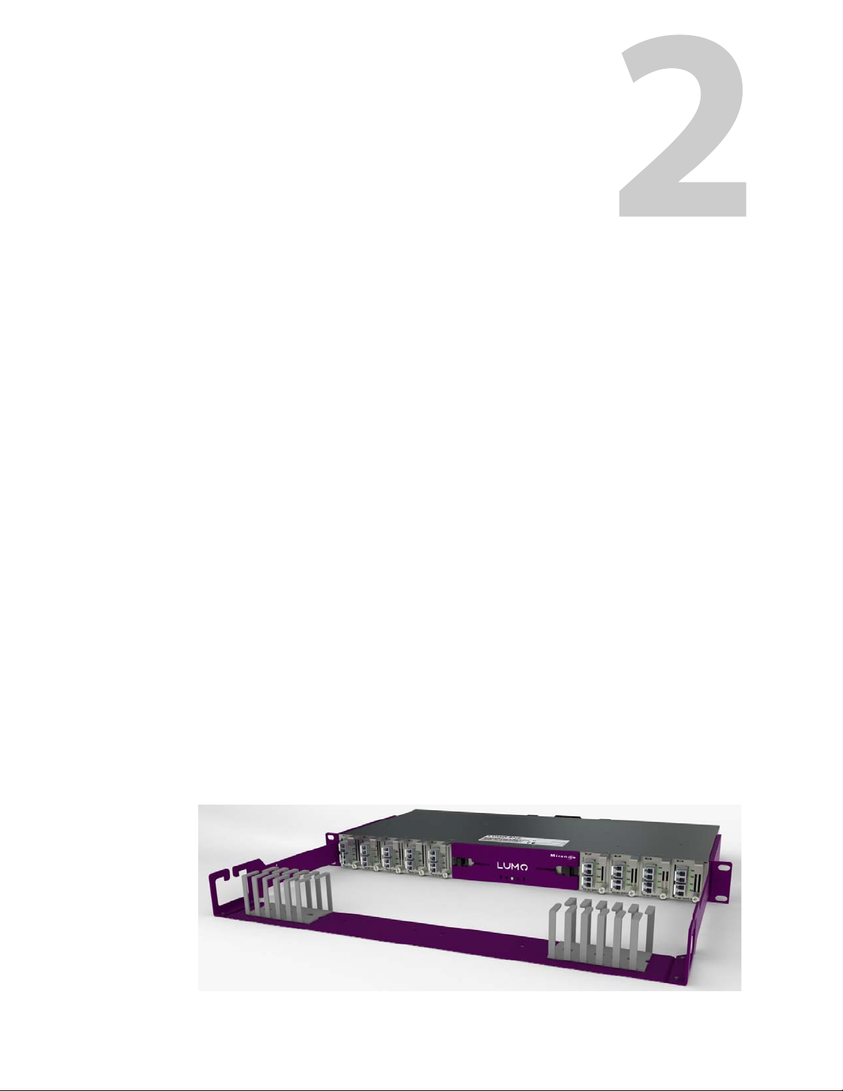
The LUMO is a high-density 1RU frame with 36 SFP-based fiber converters, ideal for large distribution of high bandwidth 3Gbps signals. LUMO’s 1RU size minimizes rack space, and oftencomplex cabling concerns have been greatly reduced by including fiber connectivity on one
side of the unit and coax electrical on the other.
Reliability and serviceability is further secured through the use of hot-swappable cards and a
redundant PSU, as well as remote system health monitoring and alarming for all key compo
nents, including optical signal strength.
Introduction
-
Key Features and Benefits
• High-density 1RU frame with 36 SFP-based fiber converters
• Supports 2 x 18 CWDM wavelengths
• Modular, hot-swappable SFPs and cards for efficient serviceability
• Mechanical design with fiber connectivity on one side and coax on the other for ease of
cabling
• Redundant, hot swappable built-in power supplies
• Remote system health monitoring and alarming for all key components
• Fiber support for convenient and secure optical fiber installation
Available Options
• LUMO-CPU-ETH controller for ethernet access and control
• Second power supply for redundant power security
1
Page 10

Introduction
Introduction to LUMO
Cards (maximum 9 per frame)
The following cards are available to be used with the LUMO frame:
These cards can be used in any combination to occupy the nine available slots in the LUMO
frame.
• FIO-911-4T-S13-LC Quad 3Gbps/HD/SD optical transmitter 1310 nm LC/PC connectors
• FIO-911-4R-LC Quad 3Gbps/HD/SD optical receiver LC/PC connectors
• FIO-911-4TH-CwwCxxCyyCzz-LC High power Quad 3Gbps/HD/SD optical CWDM Tx, LC/PC
connector.
CwwCxx and CyyCzz show the wavelengths of the CWDM transmitters used in this card.
2
Page 11
Overview
LUMO Housing Frame
Chapter 2 describes the LUMO housing frame and details of its installation.
Topics
Overview . . . . . . . . . . . . . . . . . . . . . . . . . . . . . . . . . . . . . . . . . . . . . . . . . . . . . . . . . . . . . . . . . . . . . . . . . . . . . page 3
Features . . . . . . . . . . . . . . . . . . . . . . . . . . . . . . . . . . . . . . . . . . . . . . . . . . . . . . . . . . . . . . . . . . . . . . . . . . . . . . page 4
Physical Layout . . . . . . . . . . . . . . . . . . . . . . . . . . . . . . . . . . . . . . . . . . . . . . . . . . . . . . . . . . . . . . . . . . . . . . . page 4
Assembling the LUMO Frame . . . . . . . . . . . . . . . . . . . . . . . . . . . . . . . . . . . . . . . . . . . . . . . . . . . . . . . . . page 6
Installing Cards in the LUMO Frame . . . . . . . . . . . . . . . . . . . . . . . . . . . . . . . . . . . . . . . . . . . . . . . . . . . page 8
Installing the Power Cord Retaining Clips . . . . . . . . . . . . . . . . . . . . . . . . . . . . . . . . . . . . . . . . . . . . . page 8
Ventilation . . . . . . . . . . . . . . . . . . . . . . . . . . . . . . . . . . . . . . . . . . . . . . . . . . . . . . . . . . . . . . . . . . . . . . . . . . . page 9
Field-Serviceable Items . . . . . . . . . . . . . . . . . . . . . . . . . . . . . . . . . . . . . . . . . . . . . . . . . . . . . . . . . . . . . . . page 9
Changing the Power Supply . . . . . . . . . . . . . . . . . . . . . . . . . . . . . . . . . . . . . . . . . . . . . . . . . . . . . . . . page 10
Replacing or Upgrading the Controller Card or Status Card . . . . . . . . . . . . . . . . . . . . . . . . . . page 10
Replacing the Frame Ventilation Fan . . . . . . . . . . . . . . . . . . . . . . . . . . . . . . . . . . . . . . . . . . . . . . . . page 11
Specifications . . . . . . . . . . . . . . . . . . . . . . . . . . . . . . . . . . . . . . . . . . . . . . . . . . . . . . . . . . . . . . . . . . . . . . page 12
The 1-RU LUMO housing frame and its associated LUMO-series cards are designed to provide
maximum configuration flexibility in a high density and low cost 1-RU chassis. The basic configuration includes one power supply unit and a chassis status
Up to 9 FIO-911-series cards can be installed within a single frame. The LUMO frame offers full
flexibility and integration of a variety of functions and signal types on BNC/DIN or fiber SFP. All
components are hot-swappable and can be quickly configured. The frame is air-cooled, the
PSUs and fan are monitored and status reporting is available. Each card has some multicolored
LEDs for status reporting as well. Remote control and status monitoring via Ethernet is available
as an option. The frame is available in two versions, identified by the rear connector type:
• LUMO-BNC
• LUMO-DIN
card for basic system monitoring.
3
Page 12
LUMO Housing Frame
Overview
Features
• 1 RU with 19” rack mount
• Up to 9 cards (72 Watts)
• Ease of serviceability
• Hot-swappable PSU with optional 2
• Hot-swappable cards, SFPs, controller and fan
• Status and alarm over IP with optional LUMO Ethernet Controller
• Cards can operate without controller
• Small granularity
• Fiber on the front, coax on the rear
• Multiple video and audio formats can be fitted in a single chassis
Physical Layout
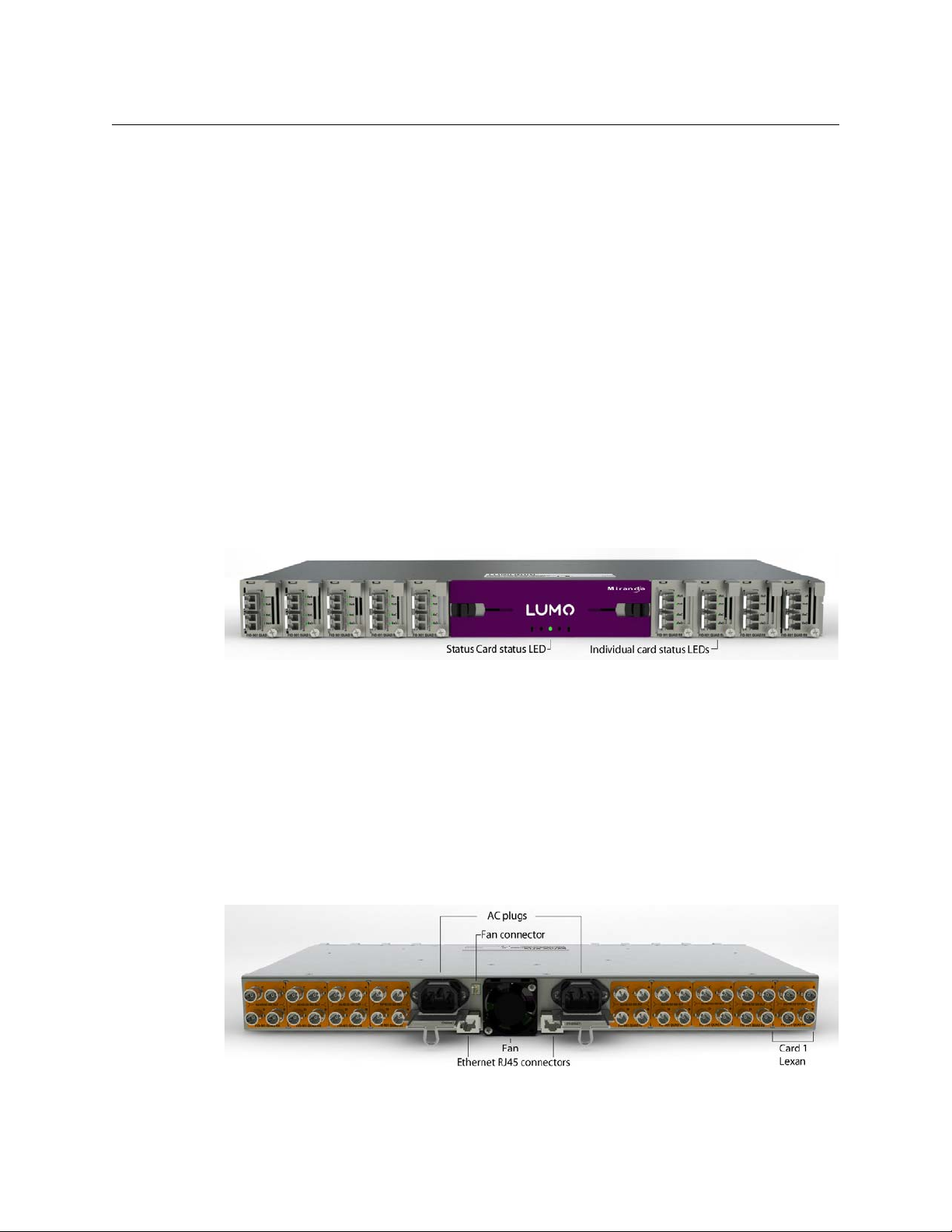
Front Panel Appearance
nd
redundant PSU
Each card (numbered 1 to 9 from left to right as seen from the front of the unit) has its own face
plate which allows the status LEDs on the installed cards to be seen and also allows the card to
be secured in the chassis by a screw. The opening near the center of the panel is for the status or
controller card status LED.
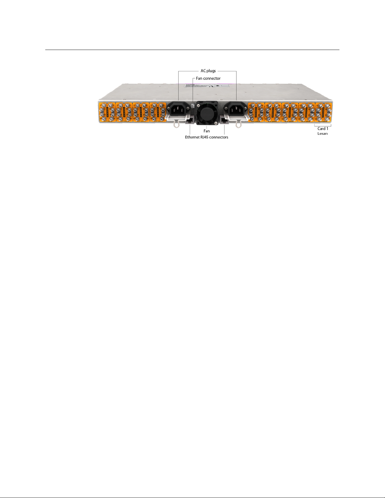
Rear Panel Appearance
The rear panel incorporates the electrical signal connectors, and so has a different appearance
for the LUMO-BNC and the LUMO-DIN. The central portion of the panel is the same for both
models.
LUMO-BNC Rear Panel
4
Page 13
LUMO-DIN Rear Panel
The functionality of Ethernet connectors is described in the Controller card chapter.
LUMO
User Manual
The details of the rear panel card lexans vary depe
Chapter 5.
Installation
Unpacking
Make sure the following items have been shipped with your LUMO frame:
nding on the card type, and are described in
• LUMO-BNC or LUMO-DIN frame, including 1 Power Supply unit (AC in) and 1 Status card
• If the optional LUMO CPU-ETH controller has been ordered, the Status card is not
included
• Rack-mounting brackets (1 pair, with 8 mounting screws)
• An AC power cord
• Power cord retaining clips (2)
• LUMO-series cards (per order) with associated lexans
• Fiber Support with 8 mounting screws
• LUMO controller card (optional)
• A second power supply and AC cord (optional)
5
Page 14
LUMO Housing Frame
Installation
Assembling the LUMO Frame
The LUMO frame is shipped with neither the frame mounting brackets nor the fiber support
installed
.
These instructions describe the insta
onto the LUMO frame.
The rack mounting brackets may be installed alone (See
fiber support.
If the rack mounting brackets are installed with the fiber support, the fiber support must be
installed first. See section B.
llation of the rack mounting brackets and the fiber support
section A), or in combination with the
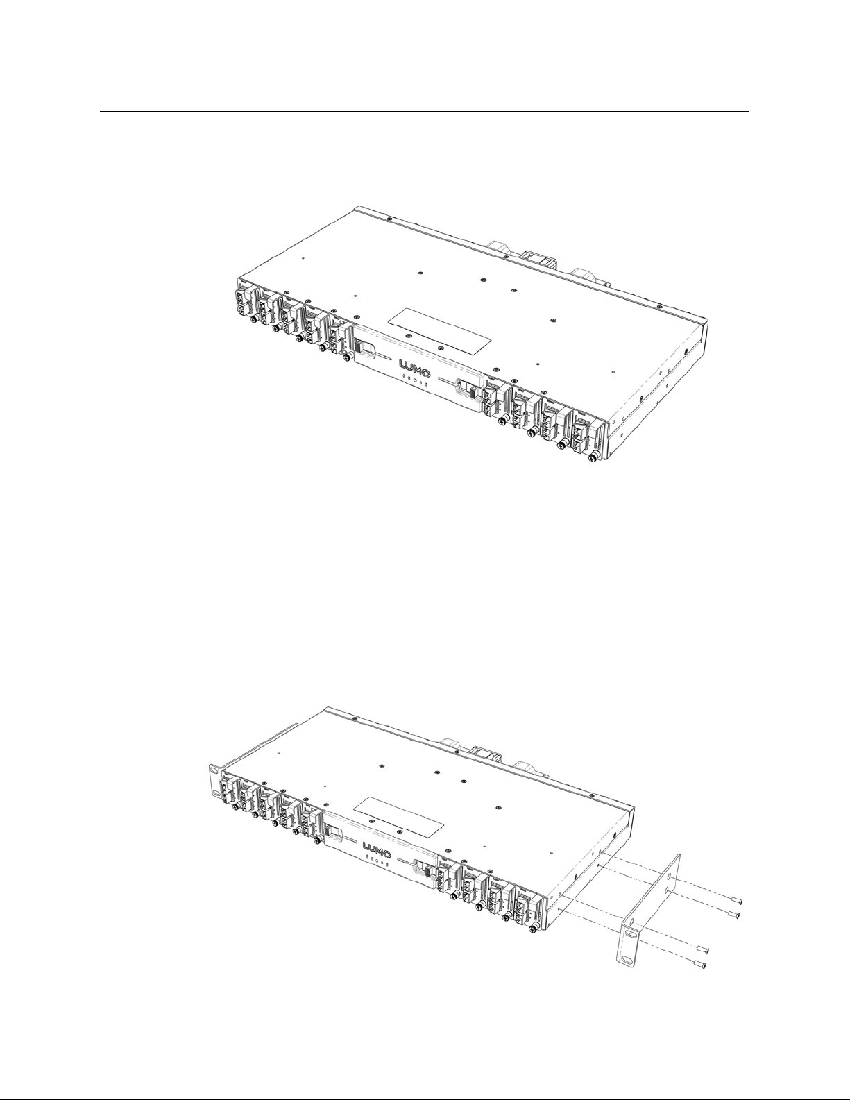
A Installing the rack mounting brackets alone
Position a bracket at each side of the LUMO frame, and install them using the four provided
screws, as shown in the Figur
e.
6
Page 15
LUMO
User Manual
B Installing the Fiber Support
If you are installing this support onto a LUMO frame which has rack mounting brackets installed,
you must remove those brackets first, and then re-install them after the fiber support has been
installed, as described in Section C.
Position the fiber support against the LUMO frame as shown in the figure , and attach it to the
frame with the eight provided screws.
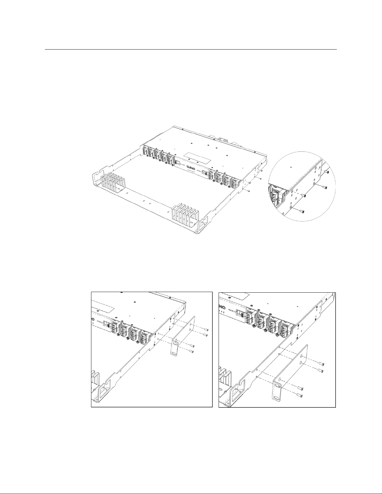
C Installing the Rack Mounting Brackets with the Fiber Support
After the fiber support is installed, you may install the rack mounting brackets in either of two
positions, using four provided screws for each bracket. The figure illustrates the two possible
mounting positions.
Once installation of the rack mount brackets is complete, the LUMO frame should be installed
directly into a standard 19” rack using 4 standard rack-mounting screws through the four holes
in the corners of the rack mount brackets.
7
Page 16
LUMO Housing Frame
Installation
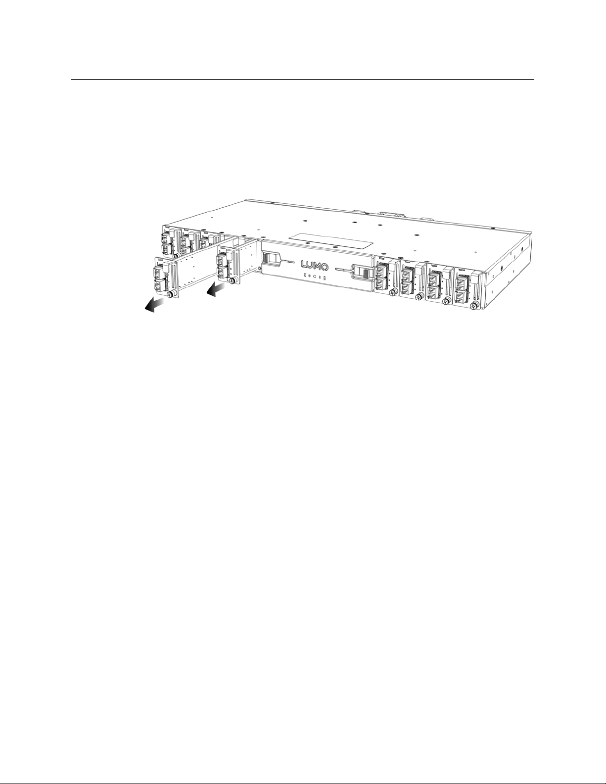
Installing Cards in the LUMO Frame
Each card includes an integrated front panel incorporating the fiber optic connectors.
All cards can be installed with the frame power on. The card has a connector which plugs into a
ba
ckplane for distribution of power, connection to the controller card, and connections to the
input and output connectors.
To install the card :
1 To remove an existing card from the slot, unscrew the existing card front panel and gently
pul
in an empty position, first remove the blank card front by unscrewing it and pulling the handle straight out of the slot.
2 Slide the new card into the slot and push gently on the handle to seat the connectors.
Secure the card in place with the provided front panel captive screw.
l the handle on the front of the card to pull the card straight out of the slot. To add a card
Slip the lexan that was shipped with the card over
rear panel that are associated with the slot into which the card was installed. The lexan identifies
the function of the connectors for that card.
Note: D
each card type.
etailed information about the rear panel connections is included in the chapters describing
the connectors ( four BNC or eight DIN) on the
Installing the Power Cord Retaining Clips
Each power supply is provided with a power cord retaining clip that holds the power cord in
place to prevent inadvertent disconnections.
With the power cord removed, install the clip into the
cord socket on the rear of the frame, by slipping the two ends of the clip into a pair of holes in
the plate, and rotating the clip down into a horizontal position. Several pairs of holes are
provided to accommodate different sizes of plugs. Use the holes that position the clip closest to
the body of the plug.
Once the clip is in place, inser
ping loop of the clip.
t the power cord into the socket, and press the cord into the grip-
plate that extends out beneath the power
8
Page 17
LUMO
User Manual
Ventilation
Ventilation for the frame is provided by a fan mounted in the center of the rear panel. The fan
draws air through the frame and exhausts it to the rear. Ventilation slots are provided in the
chassis and cards front panels to allow air to flow into the frame.
Important Note:
times when cards are installed and operating. As well, blank card front panels must be installed if no
card is present in a slot.
to ensure proper cooling, the front panel of the LUMO frame must be closed at all
Ensure that the front panel ventilation slots of the chassis and the car
Field-Serviceable Items
Field-serviceable items on the LUMO frame itself include the power supplies, the status or
controller card, and the ventilation fan.
The power supplies and status or controller card are located behind the door on the front panel.
T
he door must be opened to change the power supplies, and it must be removed to change the
status or controller card.
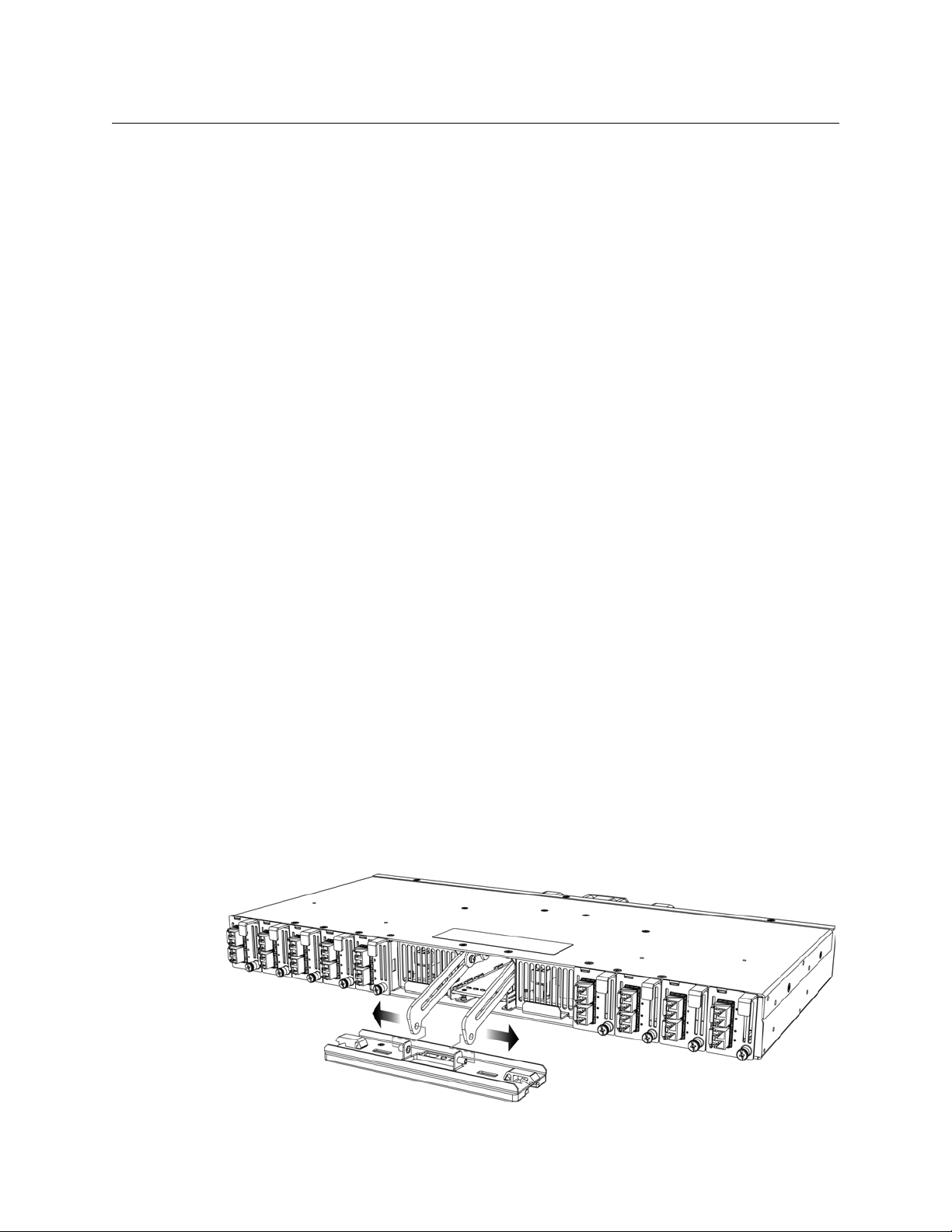
Opening and removing the front panel
The front panel of the LUMO frame is attached by swivel brackets. Two spring-loaded sliders
secure the panel in the closed position. To open the panel, pull the sliders toward the center of
the panel, and then pull the panel out until the support brackets allow it to move down below
the level of the power supplies. The supplies can then be removed.
To remove the status card, the door must be detached
push the flexible brackets apart until the door posts slip out of the holes in the brackets.
There are no electrical connec
Reinstall the panel by slipping the door posts int
door into position and snap it in place. The spring-loaded sliders will hold it in position.
ds are not obstructed.
from the frame. Once the door is open,
tions to the panel.
o the holes in the brackets, and then move the
Note that the door must be kept closed while the
frame is in use, to ensure proper ventilation.
9
Page 18
LUMO Housing Frame
Field-Serviceable Items
Changing the Power Supply
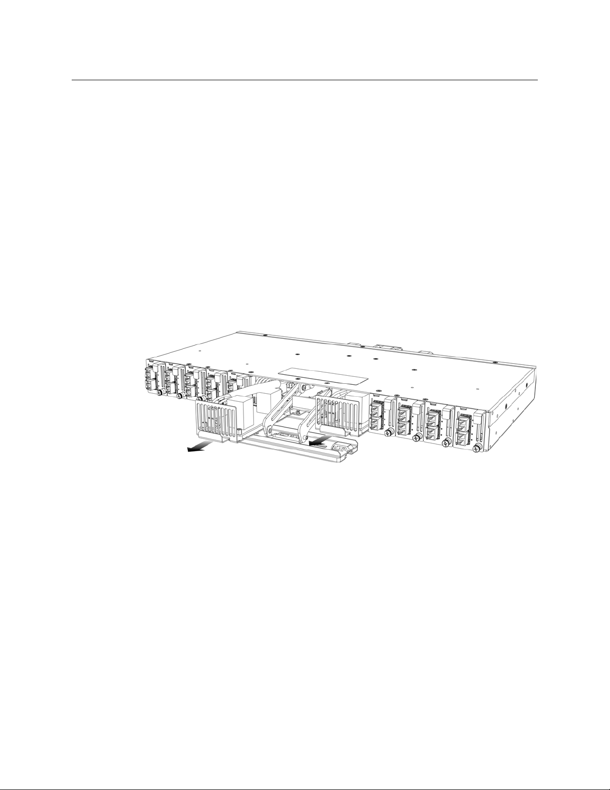
The LUMO frame supports dual redundant hot-swappable power supplies. The basic configuration includes a single supply, plus an empty sl
Installing a second power supply module and applying power to it automatically engages the
redundant supply mode. Each power supply has its own power socket on the rear panel, and
should be connected to the AC supply using the supplied power cord or other approved cord.
• A single supply can be installed in either of the two slots
To install or change a power supply module:
1 Open the front panel of the frame
2 Remove the power supply module by pulling on the handle on its front panel and sliding it
out of the frame
3 Slide the new power supply module into the slot, and push it gently into position to seat the
connectors. There is no guiding slot - the supply base sits on the floor of the frame.
4 Close the front panel of the LUMO frame. The panel secures the power supplies in place.
ot for the optional redundant power supply.
10
Replacing or Upgrading the Controller Card or Status Card
The Controller or Status card is located between the power supply slots at the center of the
frame. To replace the card, proceed as follows:
1 Open the center front door, remove the door
into the frame
2 Hook your finger over the plastic diffuser mounted at the front of the card, and pull out gen-
tly until the card is released from the rear connector; then slide the card out of the frame.
3 Slide the new card into the controller slot, and push gently on the card edge to engage the
rear connectors.
and push the door mounting brackets back
Page 19
LUMO
User Manual
4 Pull the door mounting brackets back out of the frame, and re-install the door onto the
brackets.
5 Be sure to close the door before operating the LUMO system, to ensure proper ventilation.
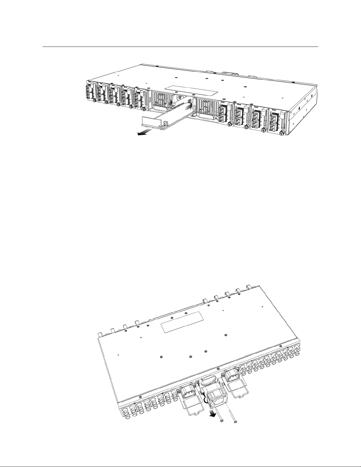
Replacing the Frame Ventilation Fan
In case of failure of the main cooling fan on the rear of the frame, replace it according to the
following steps.
1 Procure a replacement fan. It is available from Miranda as part #1974-1500-100
2 Remove the defective fan from the frame:
• Disconnect the fan power by grasping the connector and pulling straight out.
• Remove the two screws that secure the fan unit to the frame and pull the fan unit away
from the frame.
• Retain the screws, as they will be used with the replacement fan.
11
Page 20

LUMO Housing Frame
Specifications
3 Install the replacement fan:.
Specifications
MECHANICAL
Dimensions 1RU x 17.60” W (447 mm) x 10” D (254 mm) without fiber support
Weight: 8.9 lbs (4.45 kg) with 1 PSU and controller card installed
• Use the two screws that were retained when the old fan was removed to install the new
fan onto the rear panel. See the note above.
• Grasp the power connector attached to the fan assembly, and push it onto the power
outlet located to the left of the fan on the rear panel
1RU x 17.60” W (447 mm) x 20.25” D (515 mm) with fiber support
with connectors
POWER
Rating: 100-240V~
0.83 - 0.42 A
50/60 Hz
150 W max
Ambient Temperature: 40° C max
COOLING
Fans: 1 on frame, removable
COMMUNICATION
Connectors: RJ45 (2)
Compliant to: 10BaseT/100BaseTx
12
Page 21

Overview
Status Card
Chapter 3 describes the installation and functionality of the LUMO chassis status card.
Topics
Overview . . . . . . . . . . . . . . . . . . . . . . . . . . . . . . . . . . . . . . . . . . . . . . . . . . . . . . . . . . . . . . . . . . . . . . . . . . . page 13
Features . . . . . . . . . . . . . . . . . . . . . . . . . . . . . . . . . . . . . . . . . . . . . . . . . . . . . . . . . . . . . . . . . . . . . . . . . . . . page 13
Block Diagram . . . . . . . . . . . . . . . . . . . . . . . . . . . . . . . . . . . . . . . . . . . . . . . . . . . . . . . . . . . . . . . . . . . . . page 14
Installation . . . . . . . . . . . . . . . . . . . . . . . . . . . . . . . . . . . . . . . . . . . . . . . . . . . . . . . . . . . . . . . . . . . . . . . . . page 14
Card-Front Status LED . . . . . . . . . . . . . . . . . . . . . . . . . . . . . . . . . . . . . . . . . . . . . . . . . . . . . . . . . . . . . . page 15
Operation . . . . . . . . . . . . . . . . . . . . . . . . . . . . . . . . . . . . . . . . . . . . . . . . . . . . . . . . . . . . . . . . . . . . . . . . . . page 15
Specifications . . . . . . . . . . . . . . . . . . . . . . . . . . . . . . . . . . . . . . . . . . . . . . . . . . . . . . . . . . . . . . . . . . . . . . page 16
The Status card for the LUMO series is a simple status report card that monitors the presence
and voltage of the power supplies, the temperature of the air flow leaving the chassis, and the
speed status of the fan and reports it on a single bi-color front panel LED. It also carries white
LEDs to illuminate the LUMO chassis front panel.
Features
• Simple LUMO chassis health monitoring card
• Monitors the presence and voltage levels of the power supplies.
• Monitors the chassis fan speed
• Monitors the temperature of the air flow leaving the chassis
• Convenient front loading design
• The LUMO Status card can be easily replaced for maintenance
• The LUMO Status card can be replaced by the LUMO Controller card with remote control/sta-
tus monitoring through iControl and iControl Web Software
13
Page 22

Status Card
Installation
Block Diagram
The following block diagram shows the functionality of the LUMO status card.
Installation
The Miranda LUMO-series Status card is installed in the center of the LUMO chassis, between the
two power supply slots.
To remove or install a LUMO status card, follow these steps:
1 Open the center front door, remove the door and push the door mounting brackets back
into the frame
2 Hook your finger over the plastic diffuser mounted at the front of the card, and pull out gen-
tly until the card is released from the rear connector; then slide the card out of the frame.
3 Slide the new card into the controller slot, and push gently on the card edge to engage the
rear connectors.
14
4 Pull the door mounting brackets back out of the
brackets.
5 Be sure to close the door before operating the LUMO system, to ensure proper ventilation.
frame, and re-install the door onto the
Page 23

Operation
LUMO
User Manual
Card-Front Status LED
The Status card monitor LED is located on the front card-edge of the LUMO Status card, and is
visible through the LUMO frame front panel. This multi-color LED indicates the health status of
the LUMO frame by color, and by flashing/steady illumination.
The table shows how the various error conditions are flagged on the LUMO status card LED.
Alarm/Status Priority Class LED
Chassis temperature over limit 1 Critical Flashing RED
Frame fan stopped 2 Critical Flashing YELLOW
12VA or 12VB missing with
PSUA or PSUB present
Frame fan low speed 4 Maintenance problem YELLOW
All good All good Green
The front LED can display only one alarm/status, so it
example if the fan is at low speed, it should display Yellow. But if at the same time the chassis
temperature is too high, then the LED will display Flashing RED instead.
Be aware that a high priority alarm can
3 Redundancy problem RED
displays only the highest priority. For
mask a lower priority one.
15
Page 24

Status Card
Specifications
Specifications
PROCESSING PERFORMANCE
Microcontroller ARM Cortex-M3
Latency: <1 second
Power: <1W
16
Page 25

Overview
LUMO-CPU-ETH Controller Card
Chapter 4 describes the installation and functionality of the LUMO-CPU-ETH Controller card in
the LUMO housing frame.
Topics
Overview . . . . . . . . . . . . . . . . . . . . . . . . . . . . . . . . . . . . . . . . . . . . . . . . . . . . . . . . . . . . . . . . . . . . . . . . . . . page 17
Features . . . . . . . . . . . . . . . . . . . . . . . . . . . . . . . . . . . . . . . . . . . . . . . . . . . . . . . . . . . . . . . . . . . . . . . . . . . . page 17
Control Interfaces . . . . . . . . . . . . . . . . . . . . . . . . . . . . . . . . . . . . . . . . . . . . . . . . . . . . . . . . . . . . . . . . . . page 18
Using the LUMO-CPU-ETH web page . . . . . . . . . . . . . . . . . . . . . . . . . . . . . . . . . . . . . . . . . . . . . . . . page 18
IP Configuration . . . . . . . . . . . . . . . . . . . . . . . . . . . . . . . . . . . . . . . . . . . . . . . . . . . . . . . . . . . . . . . . . . . . page 18
Resetting the Controller . . . . . . . . . . . . . . . . . . . . . . . . . . . . . . . . . . . . . . . . . . . . . . . . . . . . . . . . . . . . . page 21
Using the iControl interface . . . . . . . . . . . . . . . . . . . . . . . . . . . . . . . . . . . . . . . . . . . . . . . . . . . . . . . . . page 22
Card-Front Status LED . . . . . . . . . . . . . . . . . . . . . . . . . . . . . . . . . . . . . . . . . . . . . . . . . . . . . . . . . . . . . . page 23
Configuring the LUMO-CPU-ETH Controller . . . . . . . . . . . . . . . . . . . . . . . . . . . . . . . . . . . . . . . . . page 23
Specifications . . . . . . . . . . . . . . . . . . . . . . . . . . . . . . . . . . . . . . . . . . . . . . . . . . . . . . . . . . . . . . . . . . . . . . page 34
The LUMO-CPU-ETH Controller installed in the LUMO frame supports all on-frame communication between cards, and incorporates a web page for local control and adjustment of the frame.
The LUMO-CPU-ETH Controller serves as the communications port for control and alarm infor
mation entering and leaving the frame. The LUMO-CPU-ETH controller features two Ethernet
ports for system-wide monitoring and control of the frame, using Miranda’s control solutions or
a third party monitoring system. This controller card is compatible with the TCP/IP protocol and
can support polling or report on error modes (unsolicited messaging).
-
Features
• Dual Ethernet RJ-45 ports (10/100Base-T) with static IP address configuration - same address
for both ports, which are configured for active backup redundancy.
• Provides ultra-robust Ethernet connectivity for LAN/WAN
• Controls up to 9 LUMO cards of any type
• Linux-based operating system for robust, mission-critical operations
• Features web page for local configuration of the controller and frame
• Can be remotely configured via iControl
• Provides card and frame health monitoring and status reporting
• Provides extensive frame monitoring:
17
Page 26

LUMO-CPU-ETH Controller Card
Control Interfaces
- Ethernet port monitoring, with communication settings and overall bit rate
- detailed bitrate and communication thoughput from individual cards
- self-monitoring with CPU load, memory usage
- Power Supply and fan status reporting
• Individual Card parameter storage for easy card swapping
• Communication speeds of up to 100 Mbps via Ethernet ports
Control Interfaces
The LUMO-CPU-ETH controller is the control point for the LUMO frame and the LUMO-series
cards installed in the frame. There are no separate operating controls on the frame or cards.
The LUMO-CPU-ETH has two available control interfaces:
• The LUMO-CPU-ETH serves its own web page with access to some operating controls
• Control panels for the LUMO-CPU-ETH can be accessed through Miranda’s iControl system.
Using the LUMO-CPU-ETH web page
The web page served by the LUMO-CPU-ETH controller provides the only means of configuring
the IP address for the controller card.
IP Configuration
Use of this page is essential for the initial configuration of the device, or re-configuration after a
reset, in order to set it up so it can be accessed via iControl on the local area network.
LUMO-CPU-ETH controllers are shipped from the factory with the following IP configuration:
• IP address:
• Subnet mask:
In addition, the LUMO-CPU-ETH IP address will be reset to this value if the front-panel RESET
button is pushed. See the detailed instructions for the reset process on
It is necessary to change these settings to integrate the LUMO frame into the local network
setup before it can be accessed using iControl. Proceed as follows:
1 Configure a stand-alone computer with the following IP address:
• IP address:
• Subnet mask:
2 Connect the stand-alone computer to the ETH1 port on the LUMO frame (with the LUMO-
CPU-ETH controller installed, and powered up), using a crossover ethernet cable.
192.168.3.31
255.255.0.0
page 21.
192.168.x.x
255.255.0.0
18
Page 27

LUMO
User Manual
3 Start a browser on the stand-alone computer, and browse to the LUMO’s factory IP address
as given above. The LUMO’s web page will open in the browser.
19
Page 28

LUMO-CPU-ETH Controller Card
Control Interfaces
4 Select Setup > Ethernet in the menu on the left to open the ethernet setup page.
5 On the SETUP | Ethernet page, enter the required information. Consult your IT department if
necessary.
Hostname: The hostname is the unique name by which this LUMO is known on the network. The hostname should be 15 characters or less. The hostname may contain only the
ASCII letters 'a' through 'z' (case-insensitive), the digits '0' through '9', and the hyphen
DHCP: (Disabled for this controller)
IP address: Enter an address appropriate for the local network
Network Mask: Enter a mask value appropriate for the local network
Gateway: Enter a gateway address appropriate for the local network
6 Click the Apply button to save your changes
7 Disconnect the stand-alone computer from the LUMO.
The LUMO frame is now ready to be installed in its operating location and connected to the local
network.
Once it is installed, the LUMO web page can be accessed via the network at any time using a
browser and the IP address set in the controller using the above procedure.
20
Page 29

LUMO
RESET button
Status LED
User Manual
Resetting the Controller
IMPORTANT: If for any reason you cannot connect to the LUMO frame through the network
using the address you have entered:
1 Press the RESET button on the
front panel (access it through the
cutout on the panel - it is recessed
to protect against accidental activation)
2 You must keep pressing the button
for approximately 10 seconds in
order to reset the controller. During
that time, the front panel status
LED will flash yellow. You can abort
the reset at any time while the LED
is flashing by releasing the button.
3 Once the LED has stopped flashing, the LUMO-CPU-ETH will reboot, and the IP address
(along with other on-board parameters) will be reset to its factory values.
4 Follow the steps in IP Configuration on page 18 to set the IP address to the required value.
If you can connect to the LUMO-CPU-ETH controller through the network, you can reset the IP
address by browsing to the controller’s IP address, and following steps 4-6 in the
tion on page 18.
Once you have applied the changes, your browser will lose contact with the controller, but you
may re-establish contact at the new IP address.
IP Configura-
21
Page 30

LUMO-CPU-ETH Controller Card
Control Interfaces
Using the iControl interface
The LUMO-CPU-ETH controller supports remote operation through its two rear-panel 10/100
Base-T ethernet ports, using Miranda’s iControl or a third-party solution. This manual describes
the control panels associated with the LUMO-CPU-ETH and their use.
Note -
you must configure the LUMO-CPU-ETH controller with an appropriate IP address before
it can be accessed on your network by iControl. See IP Configuration on
Please consult the iControl User’s Guide for information about setting up and operating
iC
ontrol.
In iControl Navigator or iControl Websites,
double
-click on the icon of the controller to
open its control panel.
• LUMO-CPU-ETH controllers are identified
as LUMO Controller in the Type column of
the iControl Navigator window.
• For convenience, enter a descriptive Label
in the Info panel of the card, to make it
easy to locate this specific frame controller
amongst those in the list. See Identifica-
tion on page 24 for instructions.
page 18 for details.
.
The iControl panel for the LUMO-CPU-ETH
controller displays a series of buttons down
th
e left-hand side. Clicking a button changes
the contents of the main window to display
status reports and controls related to the topic
named on the button.
A full description of the use of the iControl
i
nterface to configure the LUMO-CPU-ETH
card is given below, beginning on page 23.
22
Page 31

LUMO
User Manual
Card-Front Status LED
The status LED is located on the lower-front card-edge of the controller module, and is visible
through the front access door of the LUMO frame. This multi-color LED indicates the status of
the controller card by color, and by flashing/steady illumination.
The table shows how the various error conditions are flagged on the LUMO-CPU-ETH status LED.
Alarm/Status Priority LED
Power supply failure 1 FLASHING RED
Fan failure 1 FLASHING RED
Internal error 2 RED
Normal (no errors) GREEN
The status LED can display only one alarm/status, so
example if there is an internal error, it should display RED. But if at the same time the chassis fan
has failed, then the LED will display FLASHING RED.
Be aware that a high priority alarm can
mask a lower priority one.
it displays only the highest priority. For
Configuring the LUMO-CPU-ETH Controller
This section introduces the operating features of the LUMO-CPU-ETH controller, and describes
how to access and control them using the iControl interface.
See Using the iControl interface
The following topics are covered:
Identification . . . . . . . . . . . . . . . . . . . . . . . . . . . . . . . . . . . . . . . . . . . . . . . . . . . . . . . . . . . . . . . . . . . . . . . page 24
Status Monitoring . . . . . . . . . . . . . . . . . . . . . . . . . . . . . . . . . . . . . . . . . . . . . . . . . . . . . . . . . . . . . . . . . . page 25
Network Status . . . . . . . . . . . . . . . . . . . . . . . . . . . . . . . . . . . . . . . . . . . . . . . . . . . . . . . . . . . . . . . . . . . . . page 28
Data Restoration . . . . . . . . . . . . . . . . . . . . . . . . . . . . . . . . . . . . . . . . . . . . . . . . . . . . . . . . . . . . . . . . . . . page 28
Factory Alignment . . . . . . . . . . . . . . . . . . . . . . . . . . . . . . . . . . . . . . . . . . . . . . . . . . . . . . . . . . . . . . . . . . page 30
Time Management. . . . . . . . . . . . . . . . . . . . . . . . . . . . . . . . . . . . . . . . . . . . . . . . . . . . . . . . . . . . . . . . . . page 31
Alarms . . . . . . . . . . . . . . . . . . . . . . . . . . . . . . . . . . . . . . . . . . . . . . . . . . . . . . . . . . . . . . . . . . . . . . . . . . . . . page 31
Specifications . . . . . . . . . . . . . . . . . . . . . . . . . . . . . . . . . . . . . . . . . . . . . . . . . . . . . . . . . . . . . . . . . . . . . . page 34
on page 22 for instructions on accessing the iControl interface.
23
Page 32

LUMO-CPU-ETH Controller Card
Control Interfaces
Identification
Click the Info button
The LUMO-CPU-ETHcontroller is accessible on
a network, and must be identifiable in order to
fun
ction in the iControl environment. The
identification data is entered in the iControl
INFO control panel. This panel also shows
other data that is not user-adjustable.
You can enter the following information by
click
ing and typing in the data box:
Label: al
identifies this device when it appears in iControl applications
Short Label: a
short-form label for iControl (8 characters)
Source ID: t
LUMO-CPU-ETH controller
Comments: t
The remaining data boxes show manufac
Three buttons in the panel give access to other information:
Details:
Advanced: Show
LUMO-CPU-ETH controller in the iControl network.
Remote System Administration:.
data box, which lists remote
LUMO-CPU-ETH is registered.
lows the user to define the label that
llows the user to define the
ype a descriptive name for this
ype any desired text
turing information about this card.
Reports the Firmware version, service version, and panel version for this card
s the Miranda LongID for this card. The Miranda LongID is the address of this
Opens the Joining Locators
lookup services to which this
Add: F
orce the iControl service for this LUMO-CPU-ETH to
register itself on a user-specified Jini lookup service, using
the following syntax in the data box:
24
jini://<ip_address>
where <ip_address> is the ip address of the server running the lookup service, e.g.:
Page 33

LUMO
User Manual
Remove: select one of the services listed in the window by clicking on it, and click
Remove to open a query box allowing you to delete it from the window.
Status Monitoring
The LUMO-CPU-ETH controller continuously monitors the operating condition and status of the
housing frame’s power supplies and ventilating fans. It also monitors the status and usage of its
two ethernet ports, and the status of its on-board memory, as well as the data throughput of all
cards installed in the frame.
In addition to the information displayed on the Card-Front Status LED (se
mation acquired by the controller can be viewed in the iC
controller display through the menu.
The iControl interface always displays two
ic
ons in the upper left of the window.
These report the status of the frame’s two
power supplies.
The graphic shows the possible icon
displays and the associated messages that
appear below them. Error messages are
always displayed; other status messages
appear only upon mouse-over of the icon.
ontrol interface, and on the local
e page 23), status infor-
Click the Status button
The Status panel shows status information in four categories, each accessed by clicking the
appropriate tab.
25
Page 34

LUMO-CPU-ETH Controller Card
Control Interfaces
Status - Frame
Select the Frame tab to see a report on
the status of the frame’s CPU, fans and
power supplies.
Status - Network
Select the Network tab to see a report
on the status of the two Ethernet ports
on the LUMO-CPU-ETH card.
26
Page 35

Status - Cards
Select the Cards tab to see a chart of the
current send (Tx) and receive (Rx) data
rates, and speed, for all cards installed in
the LUMO frame.
• Note that in the LUMO frame, only
slots 1 to 9 are available
For a more detailed report on the status
of a specif
control panel in iControl.
ic card, open that card’s
LUMO
User Manual
Status - LUMO-CPU-ETH Resource
Usage
Select the Advanced tab to view a report
on the usage of the controller card’s
resources:
27
Page 36

LUMO-CPU-ETH Controller Card
Control Interfaces
Network Status
Click the Network button and select the ETH tab
The status of the LUMO-CPU-ETH
controller’s two Ethernet ports is
displayed in this panel.
NOTE: The IP address for the LUMO-CPUETH controller must be set using the onboard web page. See Using the LUMO-
CPU-ETH web page on
detailed instructions.
page 18 for
The Ethernet Link R
reported in this panel.
In LUMO, this feature is always set to
Ac
tive Backup.
edundancy status is
• The two ethernet interfaces are
bonded together and configured
with the same IP address.
• In the event that the primary inter-
face fails, network traffic is automatically switched over to the backup
interface
The MAC (Media Access Control) address is reported in the data box
• The MAC address is not user-configurable.
Data Restoration
Many of the LUMO-series cards that can be installed in the LUMO frame are complex and have a
lot of data stored on-board related to their configuration and parameter values. The LUMO-CPUETH controller provides a backup of this data, which can be restored to the card when needed.
This is valuable if the card is inadvertently reconfigured, or is replaced after failure with a new
card of the same type. The saving of the current data into the controller’s memory, and restoring
the data onto the LUMO-series card, can be done manually or automatically.
28
For manual operation:
Click the Restore Point button and view the Cards tab.
The tab show a list of the slots available in the frame, with a check box, name, and status box for
each.
• The LUMO frame uses slots 1 to 9.
Click the check box to activate the Data Rest
ore feature for the card in that slot,
Page 37

-or-
LUMO
User Manual
Click the Select All box at the top to activat
Click S
ave to controller at the bottom to
copy all restorable data from the cards in
the selected
board the LUMO-CPU-ETH controller.
Click Lo
selected slots with data from the
controller’s memory. Note that a data
restore will only work if the card in the slot
is the same type as the card that was there
when the data was saved.
slots into the memory on
ad to cards to load the cards in the
e the feature for all slots in the frame.
For automatic restore and save:
Click the Restore Point button and view the Config tab.
Restore: The LUMO-CPU-ETH card can
be set up to automatically update a card
when it is
occupied by a card of the same type
wh
can be configured automatically to
replace the card that was removed,
saving a lot of time when cards are
swapped.
Click the D
the auto restore function for all the cards
in the frame.
Save: Th
configured to automatically back up the
data on the cards in its slots according to
a set schedule.
Click the Au
automatic save function.
inserted in a slot previously
ose data was saved. Thus, a new card
efault Action box to enable
e LUMO-CPU-ETH card can be
to Save box to enable the
29
Page 38

LUMO-CPU-ETH Controller Card
Control Interfaces
Set up the schedule for data backup using the controls provided.
• Schedule: Daily, Weekly, Monthly
• Start Time (UTC): Time in hours (24-hour clock) and minutes
The label and function of the pulldown at the bottom changes to follow the Schedule selection:
Schedule Label Pulldown Options
Daily Freq Every day, Weekdays
Weekly Day Sunday, Monday, Tuesday, Wednesday, Thursday, Friday, Saturday
Monthly Week Week1, Week2, Week3, Week4, Last Week
Day Sunday, Monday, Tuesday, Wednesday, Thursday, Friday, Saturday
Factory Alignment
There may be times when the LUMO-CPU-ETH settings have been adjusted and it is useful to
restore them to a normalized condition. The LUMO-CPU-ETH controller maintains a “Factory
Default” alignment in its memory, to which it can be restored at any time.
Note: Ethernet settings are not included in the F
Factory Default alignment is installed.
Click the Factory Control button
Click the Load Factory button to restore
the card to the Factory default
alignment.
actory data set, and are not changed when the
30
Page 39

LUMO
User Manual
Time Management.
The LUMO-CPU-ETH controller is time-aware, and its internal clock can be updated manually or
via NTP.
Click the Time button
Time (UTC)
The data boxes in this section display
the time and date currently held in the
card.
Enter new values in these boxes to
ch
ange the current setting. If an automatic update via NTP is not enabled,
th
e clock will continue to run using an
on-board reference, but precision is not
guaranteed.
Note - there is no backup battery for the
time
circuit, so the time must be reset
any time the card is powered down.
NTP IP address
Click the Enable NTP
addresses of NTP servers. TheLUMO-CPU-ETH card will use the first source of valid time it finds in
this list.
box to use an NTP (Network Time Protocol) source. Enter up to three IP
Alarms
The LUMO-CPU-ETH controller generates alarms for the frame in which it is installed when error
conditions are detected. These alarms are used to set the card-front Status LED and the status
icon in the top left of the iControl window.
The alarms are reported to the iControl network.
Click the Alarm Config button
31
Page 40

LUMO-CPU-ETH Controller Card
Control Interfaces
The iControl Alarm Configuration panel opens in a new window when the Alarm Config button
is clicked, and can be resized if needed. It allows the alarm reporting of the LUMO-CPU-ETH to
be configured. The panel is organized in columns.
Status/Name
This contains an expandable tree listing all the alarms reported by this LUMO-CPU-ETH
controller.
Each alarm name includes an icon that shows its current status.
The Overall alarm and GSM contribution columns contain pulldown lists that allow the level
of contribution of each individual alarm to the alarm named in the column heading to be set.
Click on the alarm status in either of these columns to show the status options that are available,
then click on one to select it. If no options appear, the alarm is not user-configurable
Overall Alarm
This column allows configuration of the contribution of each individual alarm to the Overall
Alarm associated with this card. The Overall Alarm is shown in the upper left corner of the iCon
trol panel, and also appears at the bottom of the Status/Name column.
-
GSM Contribution
This column allows configuration of the contribution of each individual alarm to the GSM Alarm
Status associated with this card. GSM is a dynamic register of all iControl system alarms, and is
also an alarm provider for external applications. The possible values for this contribution are
related to the Overall alarm contribution:
• If the Overall alarm contribution is selected as Disabled, the GSM alarm contribution can be
set to any available value
• If the Overall alarm contribution is selected as any level other than disabled, the GSM contri-
bution is forced to follow the Overall Alarm.
Levels associated with these alarms:
The alarm status list may contain some or all of the following options:
Alarm status Significance
The alarm makes no contribution (black icon)
The alarm is of minor importance (yellow icon)
The alarm is of major importance (orange icon)
The alarm is of critical importance (red icon)
The alarm exists but has no effect (used for text and composite alarms)
32
Shortcut: if you click on “Set All” at the top of one of these columns, you will open a pulldown
list that lets you assign a level to all alarms in that column simultaneously.
Once the alarms are configured, you may accept the changes or discard them:
Page 41

LUMO
User Manual
Log Events
iControl maintains a log of alarm events associated with the card. The log is useful for troubleshooting and identifying event sequences. Click in the checkbox to enable logging of alarm
ev
ents for each individual alarm.
At the bottom of the window are several other controls:
Copy to other cards
Click this button to open a panel that
allows the alarm configuration set for
this ca
rd to be copied into other
LUMO-CPU-ETH controllers in other
frames.
Select one or more destination
c
ontrollers from the list in the window
by clicking in the checkboxes, or all of
them by clicking in the All checkbox
Get alarm keys
Click this button to open a save dialog
where you can save a file containing a
list of
all alarms on this controller and
their current values, along with an
Alarm Key for each. The alarm keys are
useful for system integration and
troubleshooting.
The file is saved in .csv format
OK, Apply, Cancel
• OK accepts the settings and closes the window once the controller confirms that there are
no errors.
• Apply accepts the settings, but leaves the window open
• Cancel closes the window without applying any changes, and leaves the previous settings
intact.
33
Page 42

LUMO-CPU-ETH Controller Card
Control Interfaces
Specifications
System Interfaces
Status LED Power ON and System Status
Ethernet Ports (2) IEEE802.3 10/100 Base-T on RJ45
Power: <3W
34
Page 43

FIO-911 O/E and E/O Converters
Chapter 5 describes the FIO-911-series optical/ electrical and electrical/opticalconverters that
are available for the LUMO housing frame.
Topics
FIO-911 3G/HD/SD Optical to/from Electrical Converters . . . . . . . . . . . . . . . . . . . . . . . . . . . . page 35
Features . . . . . . . . . . . . . . . . . . . . . . . . . . . . . . . . . . . . . . . . . . . . . . . . . . . . . . . . . . . . . . . . . . . . . . . . . . . . page 35
Description . . . . . . . . . . . . . . . . . . . . . . . . . . . . . . . . . . . . . . . . . . . . . . . . . . . . . . . . . . . . . . . . . . . . . . . . . page 36
Installing cards and SFP modules . . . . . . . . . . . . . . . . . . . . . . . . . . . . . . . . . . . . . . . . . . . . . . . . . . . page 36
FIO-911-4R-LC . . . . . . . . . . . . . . . . . . . . . . . . . . . . . . . . . . . . . . . . . . . . . . . . . . . . . . . . . . . . . . . . . . . . . . page 36
FIO-911-4T-S13-LC . . . . . . . . . . . . . . . . . . . . . . . . . . . . . . . . . . . . . . . . . . . . . . . . . . . . . . . . . . . . . . . . . . page 38
FIO-911-4TH-CwwCxxCyyCzz-LC . . . . . . . . . . . . . . . . . . . . . . . . . . . . . . . . . . . . . . . . . . . . . . . . . . . . page 39
iControl Interface . . . . . . . . . . . . . . . . . . . . . . . . . . . . . . . . . . . . . . . . . . . . . . . . . . . . . . . . . . . . . . . . . . . page 41
Specifications . . . . . . . . . . . . . . . . . . . . . . . . . . . . . . . . . . . . . . . . . . . . . . . . . . . . . . . . . . . . . . . . . . . . . . page 48
FIO-911 3G/HD/SD Optical to/from Electrical Converters
The FIO-911 series are flexible serial digital video To/From Fiber Optic converters for the LUMO
housing frame (both -BNC and -DIN versions). The FIO-911 series are designed for SD, HD and 3G
serial video as well as compressed bit-streams (DVB-ASI). The series supports any data rate
within the range of 19.4 Mbps to 2.97 Gbps and provides a reclocked serial digital video from
270Mbps to 2.97 Gbps.
The FIO-911 series offers three different configurations:
• Quad fiber Tx, with two dual optical transmitters
• Quad fiber Tx CWDM, with two dual high-power optical transmitters
• Quad fiber Rx, with two dual optical receivers
The series is based on SFP modules that provide easy product maintenance and flexibility when
multiple wavelengths are needed (as for CWDM). The SFP Modules are also hot-swappable.
Features
• Supports any serial data rate from 19.4 Mbps (ATSC) to 2.97 Gbps (3G SDI)
• Reclocked serial digital video for 270 Mbps, 1.49 Gbps, and 2.97 Gbps
• Provides unidirectional interface between fiber optic and serial digital
• Supports Multiple wavelength from the standard 1310 nm to multiple CWDM wavelengths
• Ideal for long video run with “Hum” immunity
35
Page 44

FIO-911 O/E and E/O Converters
FIO-911-4R-LC
• Presence/loss of signal alarm – iControl, on-board LED for presence
• SFP Optical power monitoring and report
• Internal SFP temperature alarms on the iControl interface
• SFP Module type detection and card configuration
• Remote monitoring and control
• Convenient front-loading design, SFP on the front of the card
• The cards and the SFP modules are fully hot swappable
Description
The FIO-911 card incorporates two SFP module slots on its front panel. Each slot has two dedicated status LEDs. The front panel also incorporates ventilation slots, a handle used to remove
the card from its slot in the LUMO frame, and a captive screw to secure it in position.
Within the frame, the card connects to intra-frame data and power busses, and to the connectors (four BNC or eight DIN) dedicated to its slot on the frame’s rear.
The front panel of the card is labeled to identify the FIO variant, and each status LED is labeled.
The function of the rear-panel connectors depends on the FIO-911 variant that is installed, and
is identified by a lexan that slips over the connectors on the rear panel. Lexans are supplied for
both -BNC and -DIN versions of the frame.
Installing cards and SFP modules
See Installing Cards in the LUMO Frame on page 8 for detailed instructions for installing the FIO-
911 cards in the LUMO frame.
See SFP Modules on page 51 for instructions on removing and installing SFP modules into the
FIO-911 front panel slots.
FIO-911-4R-LC
Quad 3 Gbps/HD/SD Optical Receiver with LC/PC Connector
This variant utilizes two dual optical receivers at its inputs to receive four channels, each of
which is O-to-E converted, reclocked and sent to the outputs (one BNC or two DIN) on the rear
panel of the housing frame.
36
The FIO-911-4R-LC Quad Receiver includes two SFP-RR-LC modules.All receiver channels are
wideband, responding to wavelengths ranging from1260 to 1620 nm, compatible with 1310 nm
and CWDM wavelengths.
The front panel and rear lexans (DIN and BNC) for this model are shown here:
Page 45

Lexan for DIN frame
Lexan for BNC frame
The functional block diagram of
the FIO-911 Quad Rx model is
shown here.
LUMO
User Manual
Note that the second outputs (A2,
B2, C2, D2) are only available on
the LUMO-DIN frame.
Card-Front Status LEDs
These LEDs monitor the status of the optical inputs to the FIO-911 Quad Rx:
• Green = Optical signal OK
• Yellow = No lock
• Flashing Yellow = Input level too high or too low
• Red = No signal
• Flashing Red = SFP not present, or SFP not detected, or hardware failure
37
Page 46

FIO-911 O/E and E/O Converters
Lexan for DIN frame
Lexan for BNC frame
FIO-911-4T-S13-LC
FIO-911-4T-S13-LC
Quad 3 Gbps/HD/SD Optical Transmitter 1310 nm with LC/PC
connector
This variant utilizes two dual optical transmitters at its outputs to send four channels, each of
which enters on a rear-panel connector, is equalized, reclocked, E-to-O converted, and sent to
the SFP transmitter. For the DIN frame only, each electrical input is also reclocked and sent to the
matching electrical output on the rear panel.
The FI0-911-4T-S13-LC Quad Transmitter includes two SFP-TT-S13S13-LC modules.
The front panel and rear lexans (DIN and BNC) for this model are shown here:
38
The functional block diagram
of the FIO-911 Quad Tx model
is sho
wn here.
Note that the electrical loop
outputs a
the LUMO-DIN frame.
re only available on
Page 47

Card-Front Status LEDs
These LEDs monitor the status of the electrical inputs to the FIO-911 Quad Tx:
• Green = SDI signal OK
• Yellow = No lock
• Red = No signal
• Flashing Red = SFP not present, or SFP not detected, or hardware failure
FIO-911-4TH-CwwCxxCyyCzz-LC
High Power Quad 3 Gbps/HD/SD Optical CWDM Transmitter
with LC/PC connector
This variant utilizes two dual high-power CWDM optical transmitters at its outputs to send four
channels, each of which enters on a rear-panel DIN, is equalized, reclocked, E-to-O converted,
and sent to the SFP transmitter. For the DIN frame only, each electrical input is also reclocked
and sent to the matching electrical output on the rear panel.
LUMO
User Manual
The two signals entering each CWDM transmitter module are modulated at different
wav
elengths.
The model number for this device identifies the tw
mitter modules by specifying the
CwwCxx and CyyCzz Wavelength (nm) Color Code
C27C29 1271/1291 Light Purple
C31C33 1311/1331 Yellow Green
C35C37
C39C41 1391/1411 White
C43C45
C47C49
C51C53
C55C57 1551/1571 Yellow
C59C61 1591/1611 Red
wavelengths of their output:
1351/1371 Pink
1431/1451 Black
1471/1491 Gray
1511/1531 Blue
o included SFP high-power CWDM trans-
Note that both SFP modules can operate at the same wavelengths.
39
Page 48

FIO-911 O/E and E/O Converters
Lexan for DIN frame Lexan for BNC frame
FIO-911-4TH-CwwCxxCyyCzz-LC
The front panel and rear lexans (DIN and BNC) for this model are shown below. Note that they
are identical to those for the FIO-911-4T-LC model. The clasp handles on the SFP modules are
color-coded to identify their wavelengths, and this will serve to distinguish the two FIO-series
products.
• Color coding for CWDM modules is shown in the above table.
The functional block diagram
of the FIO Quad High Power
WDM module is shown
C
here.
Note that the electrical loop
o
utputs are only available on
the LUMO-DIN frame
Card-Front Status LEDs
These LEDs monitor the status of the electrical inputs to the FIO-911 Quad High Power CWDM
Tx:
• Green = SDI signal OK
• Yellow = No lock
• Red = No signal
• Flashing Red = SFP not present, or SFP not detected, or hardware failure
40
Page 49

iControl Interface
When installed in a LUMO frame equipped with a LUMO-CPU-ETH controller card and
connected to a network (see
controlled using Miranda’s iControl system.
To use iControl with the FIO-911 cards, proceed as follows:
1 Install and configure your LUMO-CPU-ETH controller for network access to enable the iCon-
trol interface. See IP Configuration on page 18 for details.
2 In iControl Navigator (shown below) or iControl Websites, double-click on the icon of an
FIO-911 card to open its control panel.
LUMO
User Manual
Chapter 4), the FIO-911 cards may be remotely monitored and
• For convenience, enter a descriptive Label in the Info panel of the card, to make it easy to
locate this specific card amongst those in the list. See Identification and Information on
page 46 for instructions.
The iControl panel for the FIO-911 card displays a series of buttons down the left-hand side.
Clicking a button changes the contents of the main window to display.
The FIO-911 series of cards share the same basic control panel layout, but the detailed information within the main display window changes with the card’s functionality.
41
Page 50

FIO-911 O/E and E/O Converters
iControl Interface
Status
The Status window shows the status of
the four inputs to the card. One tab
show
s the status of inputs A and B, and
the status of their associated SFP module,
while a second tab provides the same
information for inputs C and D.
The Inputs are identified as Electrical or
Optical
, and status icons show the data
rate, Lock status, and Signal status.
The SFP module is identified by type, part
number
This is manufacturer-supplied information, read from the module.
Data about the two optical channels is
m
the SFP Info table: Temperature (C),
Voltage (V), Optical Power (dBm), and
Wavelength (nm)
, serial number and date code.
onitored on the card, and reported in
Reclocker and Optical
The Reclocker and Optical window allows
the user to choose whether the signal
reclockers at
BYPASSED.
• Reclocker control is provided for both
electrical and optical inputs
• A separate control is provided for
each of the four inputs A, B, C and D.
• The default setting is ON.
For FIO-911 cards with optical outputs,
c
ontrols are provided to turn the optical
transmitters in the SFP modules ON or
OFF for outputs A, B, C and D individually.
• The default setting is ON.
the inputs are ON or
42
Page 51

Factory Reset
The FIO-911 card can be reset to factoryspecified settings of all on-board parameters by clicking the Lo
ad Factory button.
LUMO
User Manual
Alarm Configuration
The FIO-911 card detects and signals alarm conditions.
A status LED is positioned beside each fiber connection to the SFP module on the front panel of
the car
d. These four LEDs report the status of their associated channel. The significance of the
LED’s appearance for each card type is given above, in the section devoted to that card.
The iControl Alarm Configuration panel opens in a new window when the Alarm C
is clicked, and can be resized if needed. It allows the alarm reporting of the LUMO-CPU-ETH to
be configured. The panel is organized in columns.
Status/Name
This contains an expandable tree listing all the alarms reported by this FIO-911 card.
Each alarm name includes an icon
Green: OK
Red: Alarm set
Black: Alarm not applicable (in this case, e.g. the
associated with them appear black.
The Ca
rd LED, Overall alarm and GSM contribution columns contain pulldown lists that allow
the level of contribution of each individual alarm to the alarm named in the column heading to
be set. Click on the alarm status in either of these columns to show the status options that are
available, then click on one to select it. If no options appear, the alarm is not user-configurable
that shows its current status:
re is no SFP for inputs A and B, so all alarms
onfig button
43
Page 52

FIO-911 O/E and E/O Converters
iControl Interface
Overall Alarm
This column allows configuration of the contribution
Alarm associated with this card. The Overall Alarm is shown in the upper left corner of the iControl panel, and also appears at the bottom of the Status/Name column.
GSM Contribution
This column allows configuration of the contribution of each individual alarm to the GSM Alarm
St
atus associated with this card. GSM is a dynamic register of all iControl system alarms, and is
also an alarm provider for external applications. The possible values for this contribution are
related to the Overall alarm contribution:
of each individual alarm to the Overall
• If the Overall alarm contribution is selected as Disabled, the GSM alarm contribution can be
set to any available value
• If the Overall alarm contribution is selected as any level other than disabled, the GSM contri-
bution is forced to follow the Overall Alarm.
44
Page 53

Levels associated with these alarms:
The alarm status list may contain some or all of the following options:
Alarm status Significance
The alarm makes no contribution (black icon)
The alarm is of minor importance (yellow icon)
The alarm is of major importance (orange icon)
The alarm is of critical importance (red icon)
The alarm exists but has no effect (used for text and composite alarms)
LUMO
User Manual
Shortcut: if y
ou click on “Set All” at the top of one of these columns, you will open a pulldown
list that lets you assign a level to all alarms in that column simultaneously.
Once the alarms are configured, you may accept the changes or discard them:
Log Events
iControl maintains a log of alarm events associated with the card. The log is useful for troubleshooting and identifying event sequences. Click in the checkbox to enable logging of alarm
ev
ents for each individual alarm.
At the bottom of the window are several other controls:
Copy to other cards
Click this button to open a panel that
allows the alarm configuration set for
this ca
rd to be copied into other FIO-
911 cards in this or other frames.
Select one or more destination cards
f
rom the list in the window by clicking
in the checkboxes, or all of them by
clicking in the All checkbox
Get alarm keys
45
Page 54

FIO-911 O/E and E/O Converters
iControl Interface
Click this button to open a save dialog
where you can save a file containing a
list of
all alarms on this card and their
current values, along with an Alarm
Key for each. The alarm keys are useful
for system integration and troubleshooting.
The file is saved in .csv format
OK, Apply, Cancel
• OK accepts the settings and closes the window once the controller confirms that there are
no errors.
• Apply accepts the settings, but leaves the window open
• Cancel closes the window without applying any changes, and leaves the previous settings
intact.
Identification and Information
Click the Info button
The FIO-911 card is accessible on a network,
and must be identifiable in order to function in
the
iControl environment. The identification
data is entered in the iControl INFO control
panel. This panel also shows other data that is
not user-adjustable.
You can enter the following information by
click
ing and typing in the data box:
Label: al
identifies this device when it appears in iControl applications
Short Label: a
short-form label for iControl (8 characters).
Source ID: t
911 card.
lows the user to define the label that
llows the user to define the
ype a descriptive name for this FIO-
46
Comments: t
The remaining data boxes show manufac
ype any desired text
turing information about this card.
Page 55

Three buttons in the panel give access to other information:
LUMO
User Manual
Details:
Advanced: Show
FIO-911 card in the iControl network.
Remote System Administration:.
data box, which lists remote
911 is registered.
Reports the Firmware version, service version, and panel version for this card
s the Miranda LongID for this card. The Miranda LongID is the address of this
Opens the Joining Locators
lookup services to which this FIO-
Add: F
orce the iControl service for this FIO-901 to register
itself on a user-specified Jini lookup service, using the following syntax in the data box:
jini://<ip_address>
where <ip_address> is the ip address of the server running the lookup service, e.g.:
Remove: select one of the services listed in the window by clicking on it, and click
Remove to open a query box allowing you to delete it from the window.
47
Page 56

FIO-911 O/E and E/O Converters
Specifications
Specifications
ELECTRICAL INPUT
Signal: 3G/HD/SD SDI SMPTE 424M, 292M, and 259M-
Return loss: 15 dB for up to 1.5 GHz
Cable length: 100m at 3G
C compliant
Supported data rates:
Reclocker bypassed – all rates between 19.4
Mbps and 3 Gbps
Reclocked data at 270, 1483.5, 1485, 2967,
2970 Mbps
EN50 83-9 DVB-ASI 270 Mbps
10 dB from 1.5 GHz to 3 GHz
150m at HD
350m at SD
ELECTRICAL OUTPUT
Signal: 3G/HD/SD SDI SMPTE 424M, 292M, and 259M-
C compliant
Supported data rates:
Reclocker bypassed – all rates between 19.4
Mbps and 3 Gbps
Reclocked data at 270, 1483.5, 1485, 2967,
2970 Mbps
EN50 83-9 DVB-ASI 270 Mbps
Return loss: 15 dB for up to 1.5 GHz
10 dB from 1.5 GHz to 3 GHz
Jitter (wideband): HD/SD: < 0.2 UI p-p
3G: < 0.3 UI p-p
Rise/Fall time: HD: 135 ps max., 20% to 80%
SD: 400 – 800 ps, 20% to 80%
48
Page 57

LUMO
User Manual
OPTICAL I/O
Optical: SMPTE-297M-2006 compliant
3G/HD/SD SDI: SMPTE-424M
SMPTE-292M and
SMPTE-259M-C Compliant
RX CHANNEL (PATHOLOGICAL BITSTREAM)
Sensitivity between 1260 and 1610 nm: SD, HD and 3 Gbps: -22 dBm
Tx CHANNEL (1310 nm)
Transmit power: -5 dBm to 0 dBm
Laser type: Fabry-Perot
Tx CHANNEL (CWDM)
Transmit power: 0 dBm to +4 dBm
Laser type: DFB (Distributed Feedback)
PROCESSING PERFORMANCE
Signal path: 10 bits
Latency: < 6 ns
Power: < 4W
49
Page 58

FIO-911 O/E and E/O Converters
Specifications
50
Page 59

Chapter 6 presents information regarding the use of SFP modules in LUMO-series cards.
Topics
Introduction . . . . . . . . . . . . . . . . . . . . . . . . . . . . . . . . . . . . . . . . . . . . . . . . . . . . . . . . . . . . . . . . . . . . . . . . page 51
Cautions and Warnings . . . . . . . . . . . . . . . . . . . . . . . . . . . . . . . . . . . . . . . . . . . . . . . . . . . . . . . . . . . . . page 51
Installing an SFP module . . . . . . . . . . . . . . . . . . . . . . . . . . . . . . . . . . . . . . . . . . . . . . . . . . . . . . . . . . . page 52
Connecting the fiber optic cables . . . . . . . . . . . . . . . . . . . . . . . . . . . . . . . . . . . . . . . . . . . . . . . . . . . page 52
Removing the fiber optic cables . . . . . . . . . . . . . . . . . . . . . . . . . . . . . . . . . . . . . . . . . . . . . . . . . . . . . page 53
Removing an SFP module . . . . . . . . . . . . . . . . . . . . . . . . . . . . . . . . . . . . . . . . . . . . . . . . . . . . . . . . . . . page 53
Keep the connection clean! . . . . . . . . . . . . . . . . . . . . . . . . . . . . . . . . . . . . . . . . . . . . . . . . . . . . . . . . . page 54
Introduction
The LUMO series cards incorporate a fiber optic interface. The interface consists of two parts:
SFP Modules
• Sockets on the front panel into which SFP interface modules are plugged
• SFP (Small Form-factor Pluggable) modules into which the optical fibers are plugged,
and which incorporate the optical/electrical interface
Cautions and Warnings
SFP Transmitter modules contain a class 1 laser, which emits invisible radiation
whenever the module is powered up. Because the SFP is hot-swappable, the module may be powered up as soon as it is installed.
DO NOT LOOK INTO AN OPERATING SFP MODULE’S CONNECTORS, AS EYE DAMAGE
MAY RESULT.
The SFP module is sensitive to electrostatic discharge (ESD). It is recommended that
you use an ESD-preventive wrist strap grounded to the Lumo chassis while handling
the SFP module.
SFP modules are subject to wear, and their useful lifetime is reduced each time they
are inserted or removed. Do not remove them more often than absolutely necessary.
Never remove or install an SFP module with the fiber optic cables connected. Damage to the cables could result.
The presence of dust and debris can seriously degrade the performance of an optical
interface. It is recommended that you insert a dust plug into the SFP module whenever a fiber optic cable is not connected.
51
Page 60

SFP Modules
Installing an SFP module
Installing an SFP module
1 Make sure that the bale clasp lever is in the closed position
2 Position the SFP module so that the recessed
slot is lined up with the tab side of the socket.
3 Slide the module straight into the socket, and
push gently until it clicks into position.
Connecting the fiber optic cables
1 Remove the dust plug from the SFP module if present
2 Verify that the exposed end of the optical fiber in the LC connector is clean
3 Carefully remove any debris if necessary.
4 Plug the LC-terminated fiber optic cable into the SFP module
52
Page 61

Removing the fiber optic cables
1 Grasp the LC fiber optic connector that is plugged into the SFP module, and pull it straight
out to disengage the optical fiber from the SFP.
• Never pull the fiber optic cable itself, as catastrophic damage may occur.
2 Insert a dust plug into the SFP module.
Removing an SFP module
1 Move the bale clasp lever to the open position.
LUMO
User Manual
2 Grasp the SFP module between your thumb and fore-
finger, and pull it straight out of the slot.
Do NOT pull on the bale clasp lever to remove the module, as it is easily damaged.
You may find that you need to wiggle the module, or
perhaps push it into the slot a bit, before it will release
and slide out.
3 Insert a dust plug into the SFP module.
53
Page 62

SFP Modules
Removing an SFP module
Keep the connection clean!
The physical interface between two optical fibers is the critical point in a fiber system. The two
fibers must be accurately aligned – that’s the job of the connector plugs and bulkheads – and be
in intimate contact with no obstructions. That’s the job of the user. The small size of the fiber,
and the even smaller size of the fiber core, means that even common dust particles can seriously
impair the transfer of light from one fiber to another.
There are a variety of cleaning solutions available to help the fiber user maintain good fiber
network performance. For best results, it should be possible for the user to perform a visual
inspection of the fiber ends to verify cleanliness.
Miranda strongly urges all users to select a cleaning method that meets their needs, and to use it
rigorously and consistently.
A few tips:
• Always use a dust plug in an empty fiber receptacle, to keep airborne particles from settling
on the fiber end
• Keep your dust plugs clean – a sealed container is a must.
• Always follow the instructions carefully when cleaning – abrasions on the fiber ends can
degrade system performance significantly
• A visual inspection will ensure that particles and liquid residue have been removed
If it’s still dirty, clean it again!
54
Page 63

Contact Us
Miranda Technical Support
For technical assistance, please contact the Miranda Technical Support center nearest you:
Americas
Office hours: 9:00 a.m. – 9:00 p.m. (EST)
Telephone: 1-800-224-7882
Fax: +1 514 335 1614
E-mail: support@miranda.com
Europe, Middle East, Africa, UK
Office hours: 9:00 a.m. – 6:00 p.m. (GMT)
Telephone: +44 118 952 3444
Fax: +44 118 952 3401
E-mail: eurotech@miranda.com
France
Office hours: 9:00 a.m. – 5:00 p.m. (GMT+1)
Telephone: +33 1 55 86 87 88
Fax: +33 1 55 86 00 29
E-mail: eurotech@miranda.com
Asia
Office hours: 9:00 a.m. – 5:00 p.m. (GMT+8)
Telephone: +852 2539 6987
Fax: +852 2539 0804
E-mail: asiatech@miranda.com
China
Telephone: +86 10 5873 1814
E-mail: asiatech@miranda.com
EMERGENCY After Hours (Global)
Toll Free: 1-800-224-7882 (US and Canada)
Telephone: +1 514 333 1772
Corporate Head Office
Miranda Technologies
3499 Douglas-B.-Floreani, St-Laurent, Quebec, Canada H4S 2C6
Telephone: +1 514 333 1772
Fax: +1 514 333 9828
Web: www.miranda.com
55
Page 64

56
Page 65

Index
A
Africa, contact . . . . . . . . . . . . . . . . . . . . . . . . . . . . . . . . . . . . . . . 55
Americas, contact
Asia, contact
. . . . . . . . . . . . . . . . . . . . . . . . . . . . . . . . . . . 55
. . . . . . . . . . . . . . . . . . . . . . . . . . . . . . . . . . . . . . . . 55
C
Cautions and Warnings . . . . . . . . . . . . . . . . . . . . . . . . . . . . . . 51
change history
China, contact
contact Miranda
Controller card
Installing or replacing
corporate office, contact
customer support
. . . . . . . . . . . . . . . . . . . . . . . . . . . . . . . . . . . . . . . ii
. . . . . . . . . . . . . . . . . . . . . . . . . . . . . . . . . . . . . . . 55
. . . . . . . . . . . . . . . . . . . . . . . . . . . . . . . . . . . . . 55
. . . . . . . . . . . . . . . . . . . . . . . . . . . 10
. . . . . . . . . . . . . . . . . . . . . . . . . . . . . 55
. . . . . . . . . . . . . . . . . . . . . . . . . . . . . . . . . . . 55
D
document
revision
. . . . . . . . . . . . . . . . . . . . . . . . . . . . . . . . . . . . . . . . . . ii
FIO-911-4T-S13-LC
Frame front panel - opening and removing
Frame ventilation fan
France, contact
. . . . . . . . . . . . . . . . . . . . . . . . . . . . . . . . . . .38
. . . . . . . . . . . . 9
. . . . . . . . . . . . . . . . . . . . . . . . . . . . . . . .11
. . . . . . . . . . . . . . . . . . . . . . . . . . . . . . . . . . . . . .55
H
High power optical transmitters . . . . . . . . . . . . . . . . . . . . . .39
hours of operation
Housing frame
Ethernet connectors
Front panel
Lexans
Rear panel
. . . . . . . . . . . . . . . . . . . . . . . . . . . . . . . . . . .55
. . . . . . . . . . . . . . . . . . . . . . . . . . . . . . . . . . . . . . . .3
. . . . . . . . . . . . . . . . . . . . . . . . . . . . . .5
. . . . . . . . . . . . . . . . . . . . . . . . . . . . . . . . . . . . . . .4
. . . . . . . . . . . . . . . . . . . . . . . . . . . . . . . . . . . . . . . . . . . .5
. . . . . . . . . . . . . . . . . . . . . . . . . . . . . . . . . . . . . . . .4
I
Introduction . . . . . . . . . . . . . . . . . . . . . . . . . . . . . . . . . . . . . . . . . .3
L
E
e-mail address . . . . . . . . . . . . . . . . . . . . . . . . . . . . . . . . . . . . . . . 55
Europe, contact
. . . . . . . . . . . . . . . . . . . . . . . . . . . . . . . . . . . . . 55
F
fax number . . . . . . . . . . . . . . . . . . . . . . . . . . . . . . . . . . . . . . . . . . 55
Features
Fiber optic cables
Fiber support
FIO-911-4R-LC
FIO-911-4TH-CwwCxxCyyCzz-LC
. . . . . . . . . . . . . . . . . . . . . . . . . . . . . . . . . . . . . . . . . . . . 35
Connecting
Disconnecting
Installation
Mounting brackets with
. . . . . . . . . . . . . . . . . . . . . . . . . . . . . . . . . . . . . 52
. . . . . . . . . . . . . . . . . . . . . . . . . . . . . . . . . . . 53
. . . . . . . . . . . . . . . . . . . . . . . . . . . . . . . . . . . . . . . 7
. . . . . . . . . . . . . . . . . . . . . . . . . . 7
. . . . . . . . . . . . . . . . . . . . . . . . . . . . . . . . . . . . . . . 36
. . . . . . . . . . . . . . . . . . . . . 39
Lexan installation . . . . . . . . . . . . . . . . . . . . . . . . . . . . . . . . . . . . .8
M
Middle East, contact . . . . . . . . . . . . . . . . . . . . . . . . . . . . . . . . .55
Miranda Technical Support
Miranda, contact
. . . . . . . . . . . . . . . . . . . . . . . . . . . . . . . . . . . . .55
. . . . . . . . . . . . . . . . . . . . . . . . . . .55
O
office hours . . . . . . . . . . . . . . . . . . . . . . . . . . . . . . . . . . . . . . . . . .55
Optical connections, cleanliness
Optical receivers
Optical Transmitters
Optical transmitters (high power)
. . . . . . . . . . . . . . . . . . . . . . . . . . . . . . . . . . . . .36
. . . . . . . . . . . . . . . . . . . . . . . . . . . . . . . . .38
. . . . . . . . . . . . . . . . . . . . . .54
. . . . . . . . . . . . . . . . . . . .39
57
Page 66

P
phone numbers . . . . . . . . . . . . . . . . . . . . . . . . . . . . . . . . . . . . . 55
Power cord retaining clips
. . . . . . . . . . . . . . . . . . . . . . . . . . . . . . . . . . . . . . . . . . . . . . . 1
Preface
. . . . . . . . . . . . . . . . . . . . . . . . . . . . 8
R
Status LED . . . . . . . . . . . . . . . . . . . . . . . . . . . . . . . . . . . 15, 20
support, contact
. . . . . . . . . . . . . . . . . . . . . . . . . . . . . . . . . . . . .55
T
technical support . . . . . . . . . . . . . . . . . . . . . . . . . . . . . . . . . . . .55
trademarks
. . . . . . . . . . . . . . . . . . . . . . . . . . . . . . . . . . . . . . . . . . . ii
revision, document . . . . . . . . . . . . . . . . . . . . . . . . . . . . . . . . . . . ii
S
SFP modules
About
. . . . . . . . . . . . . . . . . . . . . . . . . . . . . . . . . . . . . . . . . . . 51
Cautions and warnings
Installation
Removing
Status card
Features
Installation
Installing or replacing
Specifications
. . . . . . . . . . . . . . . . . . . . . . . . . . . . . . . . . . . . . . 52
. . . . . . . . . . . . . . . . . . . . . . . . . . . . . . . . . . . . . . . 53
. . . . . . . . . . . . . . . . . . . . . . . . . . . . . . . . . . . . 13, 17
. . . . . . . . . . . . . . . . . . . . . . . . . . . . . . . . . . . . . . 14
. . . . . . . . . . . . . . . . . . . . . . . . . . . . . . . 16, 34
. . . . . . . . . . . . . . . . . . . . . . . . . . 51
. . . . . . . . . . . . . . . . . . . . . . . . . . . 10
U
United Kingdom, contact . . . . . . . . . . . . . . . . . . . . . . . . . . . .55
V
Ventilation . . . . . . . . . . . . . . . . . . . . . . . . . . . . . . . . . . . . . . . . . . . 9
W
web site . . . . . . . . . . . . . . . . . . . . . . . . . . . . . . . . . . . . . . . . . . . . .55
58
 Loading...