

Page 1
User’s Guide
3922 496 30571 March 2007 v2.0
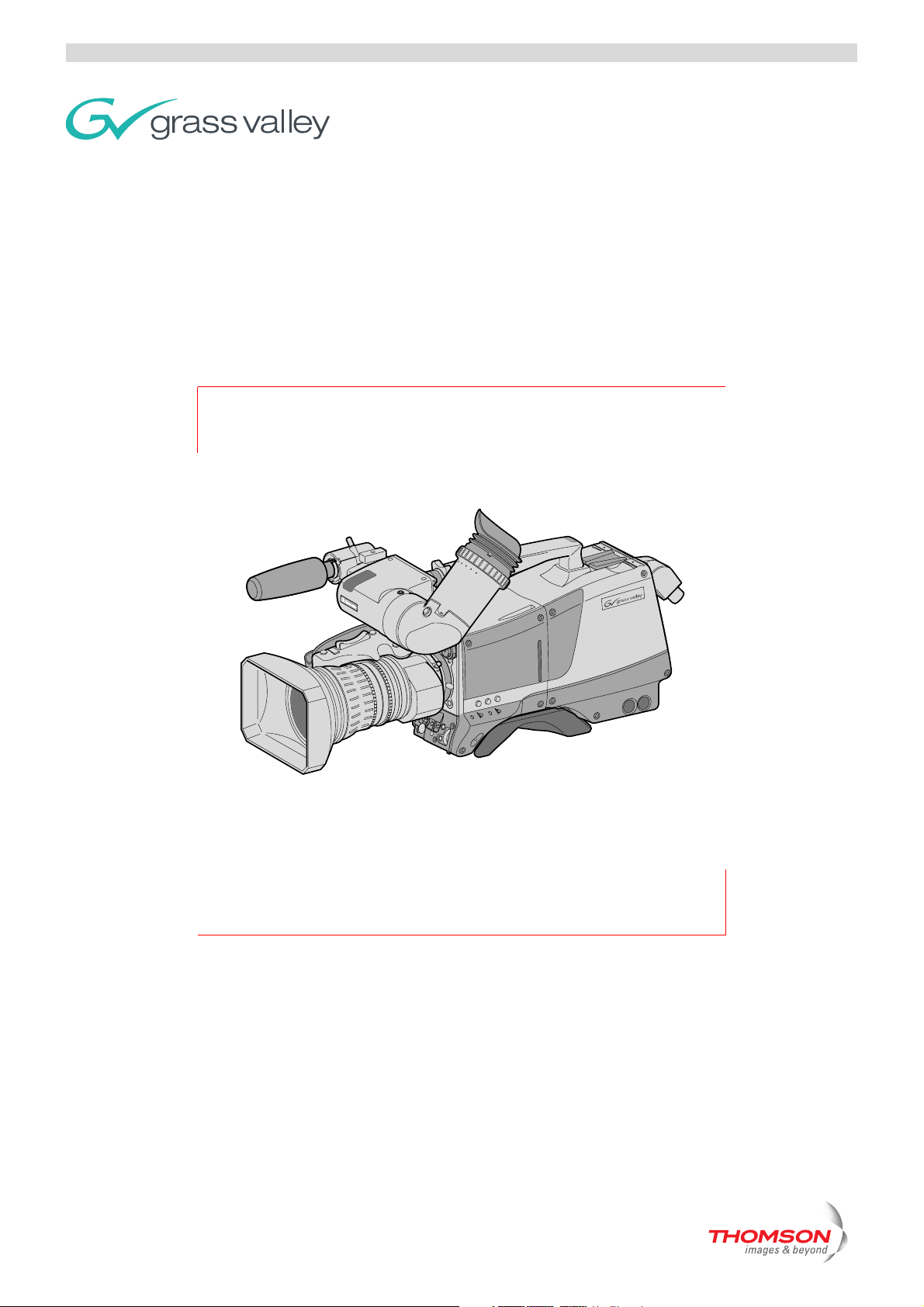
LDK 8000
HDTV multi-standard, multi-format camera system
Page 2

LDK 8000 User’s Guide ii
Declaration of Conformity
We, Grass Valley Nederland B.V., Kapittelweg 10, 4827 HG Breda, The Netherlands, declare
under our sole responsibility that this product is in compliance with the following standards:
- EN60065 : Safety
- EN55103-1: EMC (Emission)
- EN55103-2: EMC (Immunity)
following the provisions of:
a. the Safety Directives 73/23//EEC and 93/68/EEC
b. the EMC Directives 89/336/EEC and 93/68/EEC
FCC Class A Statement
This product generates, uses, and can radiate radio frequency energy and if not installed and
used in accordance with the instructions, may cause interference to radio communications.
It has been tested and found to comply with the limits for a class A digital device pursuant to
part 15 of the FCC rules, which are designed to provide reasonable protection against such
interference when operated in a commercial environment.
Copyright
Trademarks
Website
Operation of this product in a residential area is likely to cause interference in which case the
user at his own expense will be required to take whatever measures may be required to correct
the interference.
Copyright Grass Valley Nederland B.V. 2007. Copying of this document and giving it to others,
and the use or communication of the contents thereof, are forbidden without express authority.
Offenders are liable to the payment of damages. All rights are reserved in the event of the grant
of a patent or the registration of a utility model or design. Liable to technical alterations in the
course of further development.
Grass Valley and Infinity are trademarks of Grass Valley, Inc. All other tradenames referenced are
service marks, trademarks, or registered trademarks of their respective companies.
Visit the Grass Valley public website to download the latest user’s guide updates and additional
information about your broadcast product:
http://www.thomsongrassvalley.com
Page 3

LDK 8000 User’s Guide i
Table of contents
Chapter 1 – Introduction
1.1 Technology. . . . . . . . . . . . . . . . . . . . . . . . . . . . . . . . . . . . . . . . . . . . . . . . . . . . . . . . . 1-1
1.1.1 HD sensors . . . . . . . . . . . . . . . . . . . . . . . . . . . . . . . . . . . . . . . . . . . . . . . . . . . 1-1
1.1.2 Digital processing . . . . . . . . . . . . . . . . . . . . . . . . . . . . . . . . . . . . . . . . . . . . . . 1-1
1.1.3 Film-like characteristics . . . . . . . . . . . . . . . . . . . . . . . . . . . . . . . . . . . . . . . . . . 1-2
1.1.4 Focus assist . . . . . . . . . . . . . . . . . . . . . . . . . . . . . . . . . . . . . . . . . . . . . . . . . . . 1-2
1.1.5 Different versions . . . . . . . . . . . . . . . . . . . . . . . . . . . . . . . . . . . . . . . . . . . . . . 1-2
1.1.6 Acquisition formats . . . . . . . . . . . . . . . . . . . . . . . . . . . . . . . . . . . . . . . . . . . . . 1-2
1.1.7 Advanced TriaxHD features . . . . . . . . . . . . . . . . . . . . . . . . . . . . . . . . . . . . . . . 1-3
1.1.8 SuperXPander . . . . . . . . . . . . . . . . . . . . . . . . . . . . . . . . . . . . . . . . . . . . . . . . . 1-3
1.2 Features . . . . . . . . . . . . . . . . . . . . . . . . . . . . . . . . . . . . . . . . . . . . . . . . . . . . . . . . . . . 1-3
1.3 Accessories . . . . . . . . . . . . . . . . . . . . . . . . . . . . . . . . . . . . . . . . . . . . . . . . . . . . . . . . 1-5
Chapter 2 – Installation
2.1 Packing/unpacking. . . . . . . . . . . . . . . . . . . . . . . . . . . . . . . . . . . . . . . . . . . . . . . . . . . 2-1
2.2 Transport case . . . . . . . . . . . . . . . . . . . . . . . . . . . . . . . . . . . . . . . . . . . . . . . . . . . . . . 2-2
2.3 Mounting a lens . . . . . . . . . . . . . . . . . . . . . . . . . . . . . . . . . . . . . . . . . . . . . . . . . . . . . 2-3
2.4 2-inch viewfinder . . . . . . . . . . . . . . . . . . . . . . . . . . . . . . . . . . . . . . . . . . . . . . . . . . . . 2-4
2.4.1 Mounting viewfinder and microphone holder . . . . . . . . . . . . . . . . . . . . . . . . . 2-4
2.4.2 Positioning the viewfinder . . . . . . . . . . . . . . . . . . . . . . . . . . . . . . . . . . . . . . . . 2-5
2.5 Viewfinder accessories . . . . . . . . . . . . . . . . . . . . . . . . . . . . . . . . . . . . . . . . . . . . . . . 2-6
2.5.1 Wide angle eyepiece . . . . . . . . . . . . . . . . . . . . . . . . . . . . . . . . . . . . . . . . . . . . 2-6
2.5.2 Left eye adapter. . . . . . . . . . . . . . . . . . . . . . . . . . . . . . . . . . . . . . . . . . . . . . . . 2-6
2.6 Mounting a microphone . . . . . . . . . . . . . . . . . . . . . . . . . . . . . . . . . . . . . . . . . . . . . . 2-7
2.7 Tripod adapter plate . . . . . . . . . . . . . . . . . . . . . . . . . . . . . . . . . . . . . . . . . . . . . . . . . 2-8
2.8 Adjusting the shoulder pad. . . . . . . . . . . . . . . . . . . . . . . . . . . . . . . . . . . . . . . . . . . . 2-9
2.9 Attaching an adapter . . . . . . . . . . . . . . . . . . . . . . . . . . . . . . . . . . . . . . . . . . . . . . . . 2-10
Chapter 3 – Configurations
3.1 TriaxHD mode . . . . . . . . . . . . . . . . . . . . . . . . . . . . . . . . . . . . . . . . . . . . . . . . . . . . . . 3-1
3.2 Multiple TriaxHD cameras with C2IP network. . . . . . . . . . . . . . . . . . . . . . . . . . . . . 3-2
3.3 Camera with TriaxHD adapter and SuperXpander . . . . . . . . . . . . . . . . . . . . . . . . . 3-3
3.4 Local mode. . . . . . . . . . . . . . . . . . . . . . . . . . . . . . . . . . . . . . . . . . . . . . . . . . . . . . . . . 3-4
3.5 Triax cable lengths . . . . . . . . . . . . . . . . . . . . . . . . . . . . . . . . . . . . . . . . . . . . . . . . . . 3-5
Chapter 4 – Location of controls
4.1 Camera head controls and connectors . . . . . . . . . . . . . . . . . . . . . . . . . . . . . . . . . . 4-1
4.2 TriaxHD adapter controls and connectors. . . . . . . . . . . . . . . . . . . . . . . . . . . . . . . . 4-4
4.3 Viewfinder controls and indicators . . . . . . . . . . . . . . . . . . . . . . . . . . . . . . . . . . . . . 4-6
Page 4

LDK 8000 User’s Guide ii
Chapter 5 – Operating instructions
5.1 Using the camera. . . . . . . . . . . . . . . . . . . . . . . . . . . . . . . . . . . . . . . . . . . . . . . . . . . . 5-1
5.1.1 Switching on the power. . . . . . . . . . . . . . . . . . . . . . . . . . . . . . . . . . . . . . . . . . 5-1
5.1.2 Controlling the camera. . . . . . . . . . . . . . . . . . . . . . . . . . . . . . . . . . . . . . . . . . . 5-1
5.2 System Menu . . . . . . . . . . . . . . . . . . . . . . . . . . . . . . . . . . . . . . . . . . . . . . . . . . . . . . . 5-2
5.2.1 Entering the System menu . . . . . . . . . . . . . . . . . . . . . . . . . . . . . . . . . . . . . . . 5-2
5.2.2 Finding your way . . . . . . . . . . . . . . . . . . . . . . . . . . . . . . . . . . . . . . . . . . . . . . . 5-3
5.2.3 Leaving the System Menu. . . . . . . . . . . . . . . . . . . . . . . . . . . . . . . . . . . . . . . . 5-4
5.2.4 Making changes. . . . . . . . . . . . . . . . . . . . . . . . . . . . . . . . . . . . . . . . . . . . . . . . 5-4
5.2.5 Undoing changes . . . . . . . . . . . . . . . . . . . . . . . . . . . . . . . . . . . . . . . . . . . . . . . 5-4
5.3 Assigning functions to buttons. . . . . . . . . . . . . . . . . . . . . . . . . . . . . . . . . . . . . . . . . 5-5
5.4 Video acquisition modes. . . . . . . . . . . . . . . . . . . . . . . . . . . . . . . . . . . . . . . . . . . . . . 5-6
5.4.1 Standard camera version . . . . . . . . . . . . . . . . . . . . . . . . . . . . . . . . . . . . . . . . . 5-6
5.4.2 Worldcam version . . . . . . . . . . . . . . . . . . . . . . . . . . . . . . . . . . . . . . . . . . . . . . 5-7
5.5 Viewfinder preferences . . . . . . . . . . . . . . . . . . . . . . . . . . . . . . . . . . . . . . . . . . . . . . . 5-8
5.5.1 Viewfinder picture quality . . . . . . . . . . . . . . . . . . . . . . . . . . . . . . . . . . . . . . . . 5-8
5.5.2 Video level indication . . . . . . . . . . . . . . . . . . . . . . . . . . . . . . . . . . . . . . . . . . . . 5-8
5.5.3 Tally indicators . . . . . . . . . . . . . . . . . . . . . . . . . . . . . . . . . . . . . . . . . . . . . . . . . 5-8
5.5.4 Viewfinder markers . . . . . . . . . . . . . . . . . . . . . . . . . . . . . . . . . . . . . . . . . . . . . 5-9
5.5.5 Focussing. . . . . . . . . . . . . . . . . . . . . . . . . . . . . . . . . . . . . . . . . . . . . . . . . . . . . 5-9
5.6 Lens preferences . . . . . . . . . . . . . . . . . . . . . . . . . . . . . . . . . . . . . . . . . . . . . . . . . . . 5-10
5.6.1 Lens type . . . . . . . . . . . . . . . . . . . . . . . . . . . . . . . . . . . . . . . . . . . . . . . . . . . . 5-10
5.6.2 Auto iris . . . . . . . . . . . . . . . . . . . . . . . . . . . . . . . . . . . . . . . . . . . . . . . . . . . . . 5-10
5.6.3 Extended Iris . . . . . . . . . . . . . . . . . . . . . . . . . . . . . . . . . . . . . . . . . . . . . . . . . 5-10
5.6.4 Lens indicators. . . . . . . . . . . . . . . . . . . . . . . . . . . . . . . . . . . . . . . . . . . . . . . . 5-10
5.7 Video preferences . . . . . . . . . . . . . . . . . . . . . . . . . . . . . . . . . . . . . . . . . . . . . . . . . . 5-11
5.7.1 Standard settings . . . . . . . . . . . . . . . . . . . . . . . . . . . . . . . . . . . . . . . . . . . . . . 5-11
5.7.2 Test signal . . . . . . . . . . . . . . . . . . . . . . . . . . . . . . . . . . . . . . . . . . . . . . . . . . . 5-12
5.7.3 Gain selection . . . . . . . . . . . . . . . . . . . . . . . . . . . . . . . . . . . . . . . . . . . . . . . . 5-13
5.7.4 Optical filter selection . . . . . . . . . . . . . . . . . . . . . . . . . . . . . . . . . . . . . . . . . . 5-13
5.7.5 Colour temperature selection . . . . . . . . . . . . . . . . . . . . . . . . . . . . . . . . . . . . 5-14
5.7.6 Exposure time . . . . . . . . . . . . . . . . . . . . . . . . . . . . . . . . . . . . . . . . . . . . . . . . 5-18
5.7.7 Shooting screens . . . . . . . . . . . . . . . . . . . . . . . . . . . . . . . . . . . . . . . . . . . . . . 5-19
5.7.8 Black stretch . . . . . . . . . . . . . . . . . . . . . . . . . . . . . . . . . . . . . . . . . . . . . . . . . 5-20
5.7.9 Auto skin contour. . . . . . . . . . . . . . . . . . . . . . . . . . . . . . . . . . . . . . . . . . . . . . 5-20
5.8 Controls on the TriaxHD adapter . . . . . . . . . . . . . . . . . . . . . . . . . . . . . . . . . . . . . . 5-22
5.8.1 Powering the camera. . . . . . . . . . . . . . . . . . . . . . . . . . . . . . . . . . . . . . . . . . . 5-22
5.8.2 Selecting monitoring signals . . . . . . . . . . . . . . . . . . . . . . . . . . . . . . . . . . . . . 5-23
5.8.3 Using audio . . . . . . . . . . . . . . . . . . . . . . . . . . . . . . . . . . . . . . . . . . . . . . . . . . 5-24
5.8.4 Intercom. . . . . . . . . . . . . . . . . . . . . . . . . . . . . . . . . . . . . . . . . . . . . . . . . . . . . 5-25
5.8.5 Communication . . . . . . . . . . . . . . . . . . . . . . . . . . . . . . . . . . . . . . . . . . . . . . . 5-26
5.9 Managing files . . . . . . . . . . . . . . . . . . . . . . . . . . . . . . . . . . . . . . . . . . . . . . . . . . . . . 5-27
5.9.1 Scene files . . . . . . . . . . . . . . . . . . . . . . . . . . . . . . . . . . . . . . . . . . . . . . . . . . . 5-27
5.9.2 Operator files . . . . . . . . . . . . . . . . . . . . . . . . . . . . . . . . . . . . . . . . . . . . . . . . . 5-27
5.9.3 Standard files . . . . . . . . . . . . . . . . . . . . . . . . . . . . . . . . . . . . . . . . . . . . . . . . . 5-28
5.9.4 Customer standard files. . . . . . . . . . . . . . . . . . . . . . . . . . . . . . . . . . . . . . . . . 5-28
5.10 User levels . . . . . . . . . . . . . . . . . . . . . . . . . . . . . . . . . . . . . . . . . . . . . . . . . . . . . . . . 5-28
5.10.1 Selecting the user level . . . . . . . . . . . . . . . . . . . . . . . . . . . . . . . . . . . . . . . . . 5-28
5.11 Access and Security. . . . . . . . . . . . . . . . . . . . . . . . . . . . . . . . . . . . . . . . . . . . . . . . . 5-29
5.11.1 Camera cards . . . . . . . . . . . . . . . . . . . . . . . . . . . . . . . . . . . . . . . . . . . . . . . . . 5-29
5.11.2 Access control . . . . . . . . . . . . . . . . . . . . . . . . . . . . . . . . . . . . . . . . . . . . . . . . 5-30
5.11.3 Camera card slot . . . . . . . . . . . . . . . . . . . . . . . . . . . . . . . . . . . . . . . . . . . . . . 5-30
5.12 Smart-Touch™ option . . . . . . . . . . . . . . . . . . . . . . . . . . . . . . . . . . . . . . . . . . . . . . . 5-31
Page 5

LDK 8000 User’s Guide iii
Chapter 6 – Menu structure and contents
6.1 Menu structure. . . . . . . . . . . . . . . . . . . . . . . . . . . . . . . . . . . . . . . . . . . . . . . . . . . . . . 6-1
6.1.1 Top menu structure . . . . . . . . . . . . . . . . . . . . . . . . . . . . . . . . . . . . . . . . . . . . . 6-1
6.1.2 Viewfinder menu structure . . . . . . . . . . . . . . . . . . . . . . . . . . . . . . . . . . . . . . . 6-2
6.1.3 Lens menu structure . . . . . . . . . . . . . . . . . . . . . . . . . . . . . . . . . . . . . . . . . . . . 6-3
6.1.4 Video menu structure . . . . . . . . . . . . . . . . . . . . . . . . . . . . . . . . . . . . . . . . . . . 6-4
6.1.5 Install menu structure (HDriax) . . . . . . . . . . . . . . . . . . . . . . . . . . . . . . . . . . . . 6-5
6.1.6 File menu structure . . . . . . . . . . . . . . . . . . . . . . . . . . . . . . . . . . . . . . . . . . . . . 6-6
6.1.7 Security menu structure . . . . . . . . . . . . . . . . . . . . . . . . . . . . . . . . . . . . . . . . . 6-7
6.2 Menu contents . . . . . . . . . . . . . . . . . . . . . . . . . . . . . . . . . . . . . . . . . . . . . . . . . . . . . . 6-8
6.2.1 Viewfinder menu contents . . . . . . . . . . . . . . . . . . . . . . . . . . . . . . . . . . . . . . . 6-8
6.2.2 Lens menu contents . . . . . . . . . . . . . . . . . . . . . . . . . . . . . . . . . . . . . . . . . . . 6-10
6.2.3 Video menu contents. . . . . . . . . . . . . . . . . . . . . . . . . . . . . . . . . . . . . . . . . . . 6-11
6.2.4 Install menu contents . . . . . . . . . . . . . . . . . . . . . . . . . . . . . . . . . . . . . . . . . . 6-14
6.2.5 Files menu contents . . . . . . . . . . . . . . . . . . . . . . . . . . . . . . . . . . . . . . . . . . . 6-17
6.2.6 Security menu contents. . . . . . . . . . . . . . . . . . . . . . . . . . . . . . . . . . . . . . . . . 6-18
6.2.7 Diagnostics menu contents . . . . . . . . . . . . . . . . . . . . . . . . . . . . . . . . . . . . . . 6-19
6.3 Where to find a function . . . . . . . . . . . . . . . . . . . . . . . . . . . . . . . . . . . . . . . . . . . . . 6-20
Chapter 7 – Connectors
7.1 Camera connectors . . . . . . . . . . . . . . . . . . . . . . . . . . . . . . . . . . . . . . . . . . . . . . . . . . 7-1
7.1.1 Viewfinder connector. . . . . . . . . . . . . . . . . . . . . . . . . . . . . . . . . . . . . . . . . . . . 7-2
7.1.2 HDMI connector . . . . . . . . . . . . . . . . . . . . . . . . . . . . . . . . . . . . . . . . . . . . . . . 7-2
7.1.3 Lens connector . . . . . . . . . . . . . . . . . . . . . . . . . . . . . . . . . . . . . . . . . . . . . . . . 7-3
7.1.4 Audio microphone connector. . . . . . . . . . . . . . . . . . . . . . . . . . . . . . . . . . . . . . 7-3
7.1.5 RS232 serial connector . . . . . . . . . . . . . . . . . . . . . . . . . . . . . . . . . . . . . . . . . . 7-3
7.2 Connectors on the TriaxHD adapter. . . . . . . . . . . . . . . . . . . . . . . . . . . . . . . . . . . . . 7-4
7.2.1 Triax connector . . . . . . . . . . . . . . . . . . . . . . . . . . . . . . . . . . . . . . . . . . . . . . . . 7-5
7.2.2 Viewfinder / External video output connector . . . . . . . . . . . . . . . . . . . . . . . . . 7-5
7.2.3 HD - SDI (B) connector . . . . . . . . . . . . . . . . . . . . . . . . . . . . . . . . . . . . . . . . . . 7-5
7.2.4 HD - SDI (A) connector . . . . . . . . . . . . . . . . . . . . . . . . . . . . . . . . . . . . . . . . . . 7-5
7.2.5 Audio microphone 1 connector . . . . . . . . . . . . . . . . . . . . . . . . . . . . . . . . . . . . 7-6
7.2.6 Audio microphone 2 connector . . . . . . . . . . . . . . . . . . . . . . . . . . . . . . . . . . . . 7-6
7.2.7 Intercom headset connector . . . . . . . . . . . . . . . . . . . . . . . . . . . . . . . . . . . . . . 7-6
7.2.8 DC power input socket . . . . . . . . . . . . . . . . . . . . . . . . . . . . . . . . . . . . . . . . . . 7-7
7.2.9 DC power and tally output socket . . . . . . . . . . . . . . . . . . . . . . . . . . . . . . . . . . 7-7
7.2.10 Script light power supply socket . . . . . . . . . . . . . . . . . . . . . . . . . . . . . . . . . . . 7-7
7.2.11 Teleprompter output / Reference input connector . . . . . . . . . . . . . . . . . . . . . 7-8
7.2.12 Tracker communications connector. . . . . . . . . . . . . . . . . . . . . . . . . . . . . . . . . 7-8
7.2.13 Auxiliary connector . . . . . . . . . . . . . . . . . . . . . . . . . . . . . . . . . . . . . . . . . . . . . 7-9
Chapter 8 – Specifications
8.1 Specifications for LDK 8000 . . . . . . . . . . . . . . . . . . . . . . . . . . . . . . . . . . . . . . . . . . . 8-1
8.2 Specifications for LDK 5860 TriaxHD adapter . . . . . . . . . . . . . . . . . . . . . . . . . . . . . 8-2
8.2.1 Dimensions . . . . . . . . . . . . . . . . . . . . . . . . . . . . . . . . . . . . . . . . . . . . . . . . . . . 8-3
Page 6

LDK 8000 User’s Guide iv
End-of-life product recycling
Grass Valley’s innovation and excellence in product design also extends to the programs
we’ve established to manage the recycling of our products. Grass Valley has developed a
comprehensive end-of-life product take back program for recycle or disposal of end-of-life
products. Our program meets the requirements of the European Union’s WEEE Directive and
in the United States from the Environmental Protection Agency, individual state or local
agencies.
Grass Valley’s end-of-life product take back program assures proper disposal by use of Best
Available Technology. This program accepts any Grass Valley branded equipment. Upon
request, a Certificate of Recycling or a Certificate of Destruction, depending on the ultimate
disposition of the product, can be sent to the requester.
Grass Valley will be responsible for all costs associated with recycling and disposal, including
freight, however you are responsible for the removal of the equipment from your facility and
packing the equipment ready for pickup.
For further information on the Grass Valley product take back system please contact Grass
Valley at + 800 80 80 20 20 or +33 1 48 25 20 20 from most other countries. In the US and
Canada please call 800-547-8949 or 530-478-4148. Ask to be connected to the EH&S
Department. In addition, information concerning the program can be found at:
www.thomsongrassvalley.com/environment
Page 7

LDK 8000 User’s Guide v
Important information
Read these instructions carefully and retain them for future reference.
During installation and operation of this equipment, local building safety and fire protection
standards must be observed.
Before connecting the equipment to the power supply of the installation, verify the proper
functioning of the protective earth lead.
Whenever it is likely that safe operation is impaired, the apparatus must be made inoperative
and secured against any unintended operation. The appropriate servicing authority must then
be informed. For example, safety is likely to be impaired if the apparatus fails to perform the
intended function or shows visible damage.
Any changes or modifications not expressly approved in this manual could void your authority
to operate this equipment.
Cautions and Warnings
Read and comply with the warning and caution notices that appear in the manual.
• Warnings indicate danger that requires correct procedures or practices to prevent death
or injury to personnel.
• Cautions indicate procedures or practices that should be followed to prevent damage or
destruction to equipment or property.
Page 8
LDK 8000 User’s Guide vi
Warnings
To prevent fire or shock hazard, do not expose the unit to rain or moisture. If the unit is in a
wet or damp environment, a rain cover must be used to protect it for personal safety reasons
(EN60065). The rain cover supplied with the unit protects it according to safety specification
EN60529 up to level IPX2 (spraying water).
To avoid electrical shock, do not remove covers or panels. Refer servicing to qualified
personnel only.
In case of an emergency ensure that the power is disconnected.
Use only fuses of the type and rating specified.
Connect the product only to a power source with the specified voltage rating.
The Base Station must always be connected to protective earth. Do not interrupt the
protection conductor inside or outside the unit. Do not disconnect the protective earth
terminal. Intentional interruption is prohibited and is likely to make the unit dangerous.
To prevent risk of overheating, ventilate the units correctly.
For safety reasons the Base Station must be mounted in a 19-inch rack which has safety
covers according to IEC65. When two Base Stations are mounted above each other, the
minimum distance between them must be 50mm or the rack must be force-air cooled.
Page 9
LDK 8000 User’s Guide vii
Triax cable systems
Only connect a Triax cable from the same LDK camera family to the unit.
Do not allow system earth currents to exceed 1.5A in the outer shield of the Triax cable or
0.2A in other cable shields.
To avoid excessive earth currents in a Triax system, galvanically separate the power earth
connection of equipment connected to the camera from the camera earth.
It is strictly prohibited to short circuit the inner and outer shields of a Triax cable used to
connect a camera to a base station.
Galvanic separation
Because of the nature of Triax systems, with long distances between camera and Base
Station, the risk of earth currents flowing is greater. These earth currents can result in damage
to the equipment.
For example, a monitor connected directly to the CVBS output of the camera is powered
locally. The earthing point of the monitor’s power supply can be at a different potential with
respect to the earthing point of the Base Station. If the power earth of the monitor is also the
video earth, then this earth potential is transferred to the camera via the shield of the BNC
connector. The difference in earth potential between the camera and the Base Station results
in an earth current in the Triax system.
To prevent earth currents from flowing in the Triax system, we recommend galvanic
separation of earthed equipment connected to the camera. This separation can be achieved by
using an isolation transformer between the local power outlet and the equipment connected to
the camera. Alternatively, use equipment that has a double insulation and therefore does not
require an earth connection.
Page 10

LDK 8000 User’s Guide viii
Base Station earthing
The rear of the unit has two separate screw terminals for protective earth (PE) and video
earth (VE). These are normally connected by a metal strap.
VE
Metal strap
PE
The protective earth terminal is internally connected to the protective earth conductor of the
power cable. In normal circumstances the connection between the protective earth and the
video earth should not be broken. If required, the central earth connection wire of the studio
can be connected to terminal PE in accordance with VDE regulation 0800/part2.
Only if the studio (or OB van) is equipped with separate protective and video earth systems
may the metal strap be removed. Under these circumstances the video earth terminal must be
connected to the central functional earth potential (video earth) of the studio. This earth
potential should have functional protective and noiseless earth (FPE) qualities as stated in the
VDE regulation 0800/part2. A low impedance interconnection of both earth conductors must
be provided at the central studio earthing point.
Page 11

LDK 8000 User’s Guide ix
Precautions
To ensure continual high performance from the camera take the following precautions into
consideration:
• Avoid very damp places. If the environment is wet or damp a rain cover must be used to
protect the unit.
• Do not subject the unit to severe shocks or vibration.
• Do not expose the camera to extremes of temperature.
• Do not leave the unit in direct sunlight or close to heating appliances for extended periods.
• Do not allow sunlight to shine into the viewfinder.
• Do not allow LASER beams to shine into the lens as this could damage the CCD sensors.
• Avoid extreme highlights as these can cause various kinds of optical reflections.
• Be careful when connecting and disconnecting triax cables.
– Do not mix triax units from different types of camera systems (HD with SD, RGB triax
with digital triax).
– Make connections swiftly and firmly to avoid false error messages.
Mains lead wiring for UK users
The wires in the mains lead are coloured in accordance with the following code:
GREEN and YELLOW- EARTH
BLUE- NEUTRAL
BROWN- LIVE
As the colours of the wires in the mains lead of this apparatus may not correspond with the
coloured markings identifying the terminals in your plug proceed as follows:
• The wire coloured GREEN AND YELLOW must be connected to the terminal on the plug
marked with the letter E or by the safety earth symbol or coloured GREEN or GREEN
AND YELLOW.
• The wire coloured BROWN must be connected to the terminal marked with the letter L or
coloured RED.
• The wire coloured BLUE must be connected to the terminal marked with the letter N or
coloured BLACK.
Ensure that your equipment is connected correctly - if you are in any doubt consult a qualified
electrician.
Page 12

LDK 8000 User’s Guide x
Page 13

LDK 8000 User’s Guide | Introduction 1-1
Chapter 1
Introduction
1.1 Technology
The LDK 8000 is a high definition multi-standard, multi-format digital camera head using
three 2/3-inch HD-DPM
adapter for a flexible camera that is equally at home in the studio or out on location.
1.1.1 HD sensors
The camera head uses HD-DPM+™ CCD sensors which offer superior performance and
ultimate flexibility. Native wide screen pictures in the high-definition formats 1080i, 1080p
(WorldCam) and 720p are produced at the touch of a button. This unique native multi-format
capability is realized with innovative 9.2 million pixel 2/3" CCD sensors. These allow vertically
grouping of different numbers of pixels on the sensors themselves. There is no need for HDTV
format conversion during digital signal processing which would lead to quality degradation.
These sensors have a high dynamic range and high linear sensitivity across all camera lens
apertures. They are based on Frame Transfer technology, which ensures that there is neither
lag nor smear.
1.1.2 Digital processing
The advanced digital processing of the camera is based on 14-bit A/D converters and more
than 22-bit internal processing. All major camera functions are processed in the digital
domain, including knee, gamma, contour, matrix and colour correction.
The intelligent continuous automatics facility provides automatic control of black levels and
black shading. Each sensor provides black reference signals that are used to monitor
temperature changes. This means that continuous automatic correction is applied without
operator intervention.
+
™ sensors. The camera head can be combined with the TriaxHD
v2.0
The digital contour processing uses full amplitude video RGB signals via an extended dynamic
range contour circuit. Colorimetry is selected by means of a variable 6-point digital matrix or
via preset matrices. Digital gamma circuits provide a wide range of standardised gamma
curves and enable soft contrast in black scenes to be enhanced, together with hard contrast
and saturated colour in bright scenes. The matrix and gamma sequence is software
programmable for precise colour matching.
Page 14

LDK 8000 User’s Guide | Introduction 1-2
1.1.3 Film-like characteristics
The pivoting knee circuit adapts both the knee point and the compression ratio according to
the highlight content of the picture to emulate the softly limiting S-shaped transfer
characteristics of film. Digital True Colour Knee circuitry maintains the correct hue for
compressed highlights, reproducing colours faithfully, even overexposed skin tones.
Digital contrast circuitry provides a black stretch function for more detail in black areas and a
black press function for improving the contrast impression by simulating the S-curve of film.
1.1.4 Focus assist
With HDTV, focusing is even more critical than before. The LDK 8000 has special patented
focusing aids. A unique viewfinder zoom function enlarges the viewfinder image instantly
with a simple press-button action, thus providing improved means for focusing. A patented
crawler circuitry adds motion in the viewfinder to objects in sharp focus.
1.1.5 Different versions
The LDK 8000 camera head is available in two versions - Standard and Worldcam.
The Standard version supports 1080i/720p HD formats in 50, and 59.94 Hz, and
simultaneously provides high-quality SDTV outputs in either 50 Hz or 59.94 Hz.
The Worldcam version provides, in addition to the Standard version formats, digital
cinematography formats in 1080p and 720p, which give an impression of motion comparable
to film cameras running at identical speeds.
The Worldcam also provides convenient built-in frame-rate conversions for easy connection to
existing HD peripherals, offering possibilities for cost-effective monitoring and recording
combined with the motion portrayal of film cameras. The 1080p format at 23.98 Hz, for
example, can be converted using 3:2 pull-down to 1080i at 59.94 Hz right inside the camera.
1.1.6 Acquisition formats
The following acquisition formats are available:
Standard version
– 1080i at 59.94 Hz
– 1080i at 50 Hz
– 720p at 59.94 Hz
– 720p at 50Hz
v2.0
Worldcam version
– 1080i at 59.94 Hz
– 1080i at 50 Hz
– 1080p at 23.98 Hz
– 1080p at 24 Hz
– 1080p at 25 Hz
Page 15

LDK 8000 User’s Guide | Introduction 1-3
– 1080p at 29.97 Hz
– 720p at 59.94 Hz
– 720p at 50 Hz
– 720p at 23.98 Hz
– 720p at 25 Hz
– 720p at 29.97 Hz
1.1.7 Advanced TriaxHD features
TriaxHD, which is a further development of the Emmy Award winning triax transmission
system, makes the camera compatible with industry standard triax cables. This allows the
reuse of existing, reliable and valuable cable inventories.
TriaxHD allows video transmission and remote control of cameras up to a distance of 3300 ft
(1000 meters) and beyond, using industry standard 14mm triax cables. It is based on 30MHz
full-bandwidth 4:2:2 transmission (Y/Cr/Cb components).
The double side band modulation technique used in combination with Y/Cr/Cb transmission
ensures linearity, resolution and an optimal signal-to-noise ratio over the maximum cable
length. Bandwidth efficient channel combining and equalization techniques minimize crosstalk and interference. Teleprompter and viewfinder signals maintain high performance with
relatively long cable lengths.
The communication facilities provide for two-wire or four-wire high quality intercom signals.
Full camera control is provided via a C2IP Ethernet-based control network.
The TriaxHD adapter is equipped with a rotary triax connector which provides freedom of
movement during portable use of the camera and protects the connector from being
damaged in near-floor conditions.
TriaxHD Base Station
The TriaxHD Base Station, as well as providing high definition outputs, optionally offers
simultaneous high-end SDTV outputs. This facilitates a gradual and managed transition from
SDTV to HDTV.
1.1.8 SuperXPander
The Triax SuperXpander large lens adapter together with the optional 7-inch HD high
resolution viewfinder turns the portable triax camera into a full-featured studio camera for
studio and EFP situations.
1.2 Fe a tures
• Ultimate flexibility with HD-DPM+ ™ CCD sensors, offering native switchability between
the interlaced 1080i and true progressive 1080p high definition digital cinematography
formats.
v2.0
• The CCDs have 9.2 million pixels, with 1920 (H) x 4320 (V) effective picture elements.
• Frame Transfer technology ensures no smear.
Page 16

LDK 8000 User’s Guide | Introduction 1-4
• 14-bit A-to-D and more than 22-bit digital processing with unique software programmable
video path.
• Superior all digital highlight handling with a wide dynamic range.
• Unique circuitry for pivoting knee and True Colour Knee.
• Variable gain control and variable colour temperature.
• Wide range of presets and variable 6-point digital matrix assure accurate colour matching.
• Fluorescent light matrix.
• Digital gamma with unique standard preset values and highest accuracy.
• Digital contour with an extensive range of parameters.
• Advanced contour correction includes two automatic skin settings.
• Intelligent Continuous Automatics black levels, black shading and video levels - no set-up
time required.
• Digital contrast with standard black stretch and black press.
• International standard 2/3-inch lens interface.
• Optical servo-controlled four-position neutral density filter wheel.
• Optical servo-controlled effect filter wheel with soft focus, four-point star and six-point
star filters.
• Electronic colour filter can be used for creating a special look (warm/cold) of a scene, or
for a smooth colour temperature control around the white balance setting.
• Smart card for personal settings and security.
• Owner card for setting user levels, and for copying and storing control settings.
• Protected, easy-to-operate controls and switches with read-out of all settings.
• Viewfinder status read-out of primary camera functions.
• Clean scan feature allows capture of computer and other monitor pictures.
v2.0
Page 17

LDK 8000 User’s Guide | Introduction 1-5
1.3 Accessories
Xpander LDK 4489
SuperXpander LDK 4488
7” viewfinder support LDK 6517
HD/HS Triax Repeater LDK 4800
2” viewfinder HDTV LDK 5302/60
5” viewfinder HDTV LDK 5305/01
7” viewfinder HDTV High Brightness LDK 4020/20
Wide Angle adapter for 2" VF LDK 5390/00
Left eye adapter for 2” VF LDK 5390/10
Sunhood for 5" VF LDK 6992/02
Raincover for camera with 5"VF LDK 5021/05
Tripod plate LDK 5031/10
Headset dynamic XLR-5 double muff LDK 8111/37
Headset dynamic XLR-5 single muff LDK 8111/51
Scriptboard with light LDK 6985/21
Transport/flightcase LDK 5020
Carrying bag LDK 5020/01
AC power supply 100 W LDK 5901/00
v2.0
Page 18

LDK 8000 User’s Guide | Introduction 1-6
v2.0
Page 19

LDK 8000 User’s Guide | Installation 2-1
Chapter 2
Installation
2.1 Packing/unpacking
Inspect the shipping container for evidence of damage immediately after receipt. If the
shipping container or cushioning material is damaged, it should be kept until the contents of
the shipment have been checked for completeness and the units have been checked
mechanically and electrically.
The shipping container should be placed upright and opened from the top. Remove the
cushioning material and lift out the contents. The contents of the shipment should be checked
against the packing list. If the contents are incomplete, if there is mechanical damage or
defect, or if the units do not perform correctly when unpacked, notify your Grass Valley
Nederland B.V. sales or service centre within eight days. If the shipping container shows signs
of damage or stress, notify the carrier as well.
If a unit is being returned to Grass Valley Nederland B.V. for servicing, try to use the containers
and materials of the original packaging. Attach a tag indicating the type of service required,
return address, model number, full serial number and the return number which will be supplied
by your Grass Valley Nederland B.V. service centre.
If the original packing can no longer be used, the following general instructions should be used
for repacking with commercially available materials:
1. Wrap unit in heavy paper or plastic.
2. Use strong shipping container.
3. Use a layer of shock-absorbing material around all sides of the unit to provide firm
cushioning and prevent movement inside container.
4. Seal shipping container securely.
5. Mark shipping container FRAGILE to ensure careful handling.
v2.0
Page 20
LDK 8000 User’s Guide | Installation 2-2
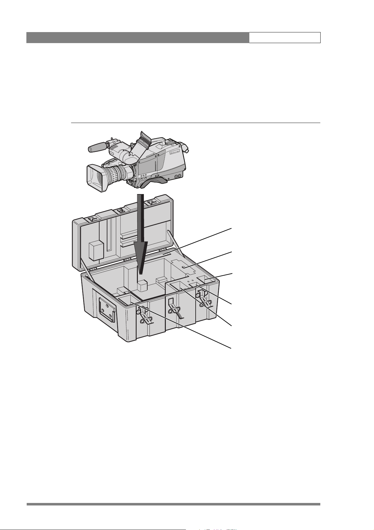
2.2 Transport case
It is important to protect your camera against damage when transporting it. To do this, a
transport case (LDK 5020/00) is optionally available for the camera, lens, viewfinder and some
accessories.
Figure 2-1. Transport case
documentation
packing inserts
top light
tripod plate
power supply
additional supplies
The camera is packed in the transport case as shown in the figure above. This ensures that the
camera is not damaged during transport. Turn the 2-inch viewfinder downwards so that it does
not protrude above the top of the camera. Several foam packing inserts are provided to enable
different configurations of the camera to be packed securely. These inserts are used to
support the rear of the camera. Make sure you use the correct foam insert for your particular
configuration.
v2.0
Page 21
LDK 8000 User’s Guide | Installation 2-3
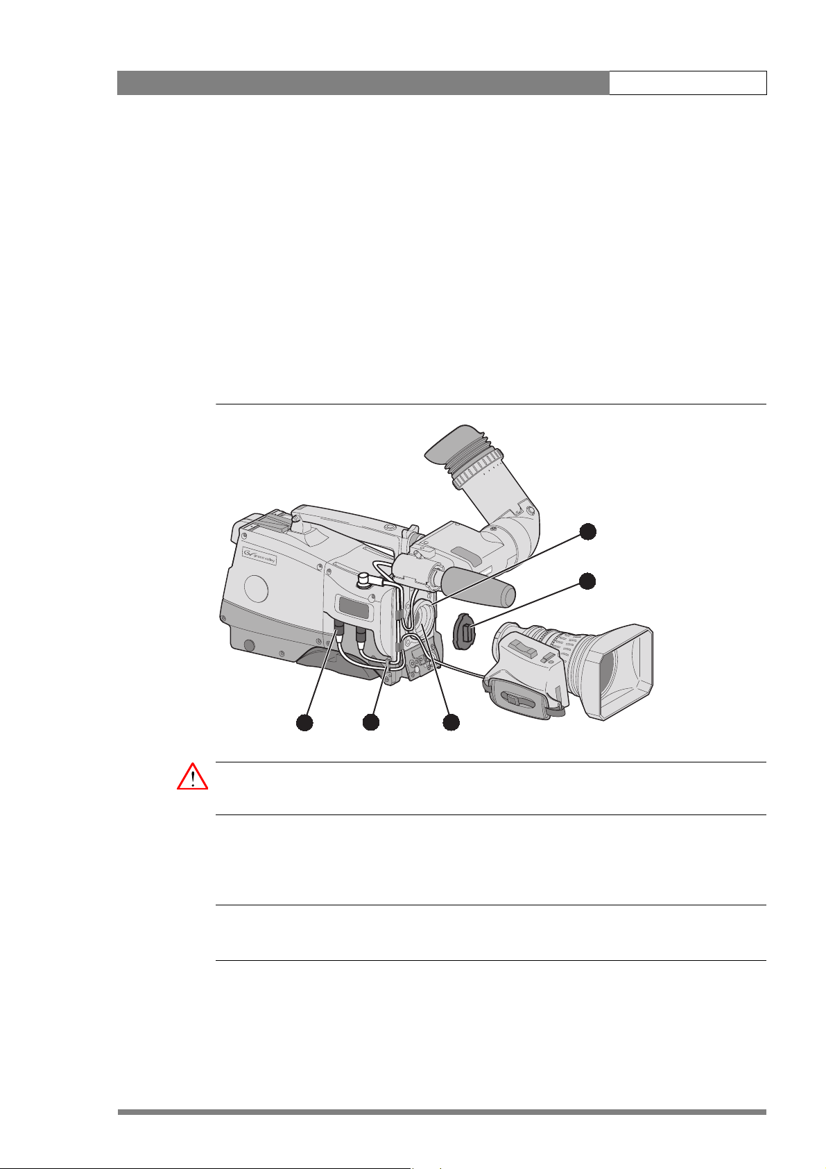
2.3 Mounting a lens
To attach a lens to the camera head proceed as follows:
1. Ensure that the lens locking ring (1) is in the unlocked position - turned counterclockwise.
2. Remove the dust protection cap (2).
3. Slot the lens into the lens mount (3).
4. Turn the lens locking ring (1) clockwise to lock the lens in place.
5. Connect the lens cable to the lens connector (4) at the right side of the camera.
6. Place the lens cable into the bottom clip at the front of the camera and clip (5) located at
the side.
Figure 2-2. Lens mounting
1
2
4
Caution
Do not attach a lens weighing more than 5 kg to the camera without a support.
When a new lens is fitted to the camera it may be necessary to carry out some adjustments to
optimize its use, for example, back focus or shading. For more information about these
adjustments refer to the lens manufacturer’s documentation.
Note
☞
Always mount the dust protection cap when the lens is not connected to the camera.
5
3
v2.0
Page 22
LDK 8000 User’s Guide | Installation 2-4
2.4 2-inch viewfinder
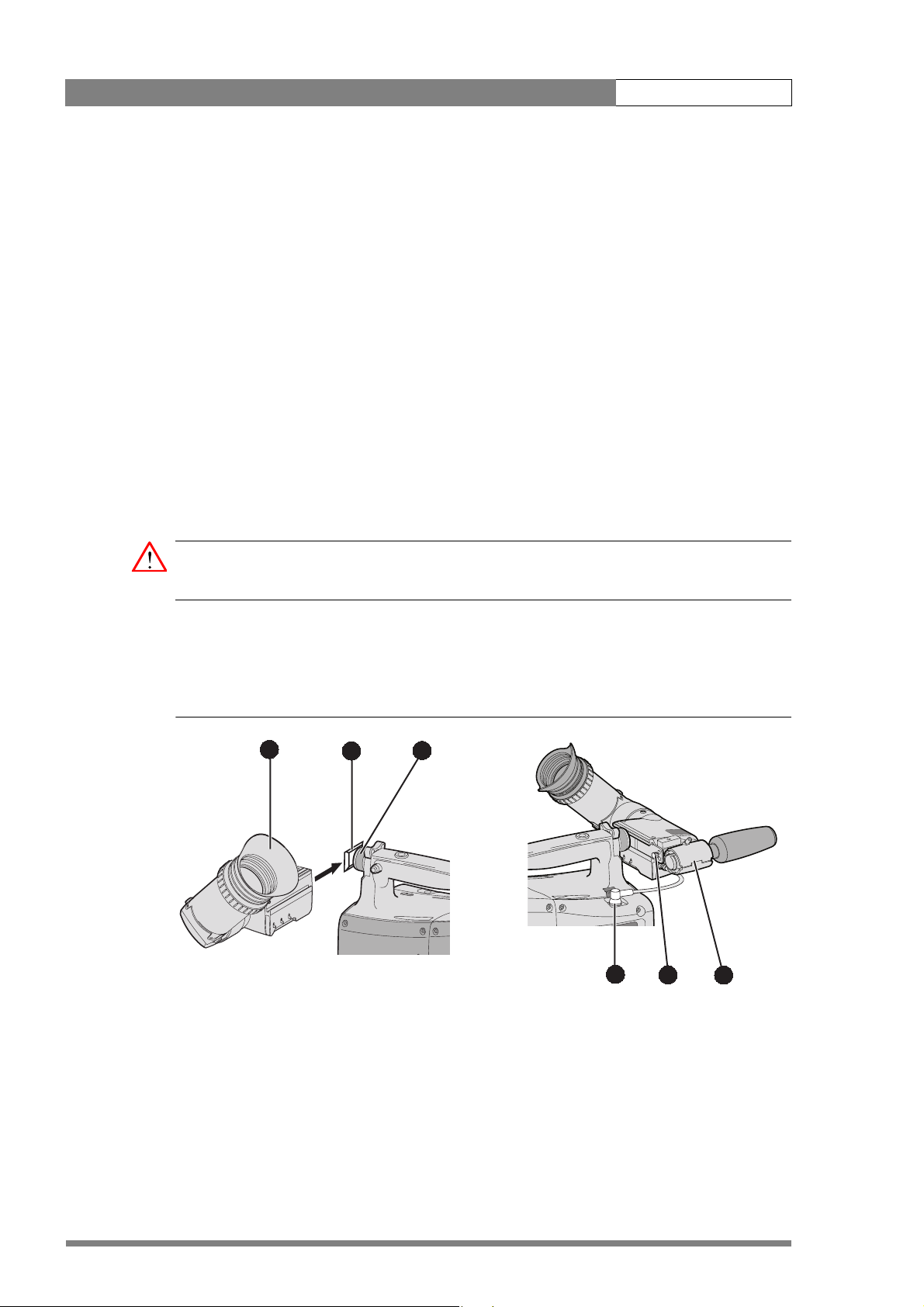
2.4.1 Mounting viewfinder and microphone holder
To mount the viewfinder LDK 5302/60 proceed as follows:
1. Loosen locking ring (1) of viewfinder support bracket (2) at the front of the camera handle.
(As seen from the rear of the camera, turning the locking ring counterclockwise moves it
towards the handle.)
2. Slide the viewfinder onto the viewfinder support bracket.
3. Tighten the locking ring (1) by turning it clockwise (as seen from rear) so that the
viewfinder is mounted securely to the support.
4. Connect the viewfinder cable to the viewfinder connector socket (6) at the top right of the
camera.
5. Slide the microphone holder (4) onto the viewfinder and secure with the knurled screw
(5).
Caution
Always fit the microphone holder as it functions as a safety stop for the viewfinder.
6. To improve the comfort of the skin contact when using the viewfinder, fit the eye piece
cover (3) to the rubber eyepiece. Spare eye piece covers (3922 405 00461) are available at
your Grass Valley representative.
Figure 2-3. Viewfinder mounting
3
2
1
6
5
4
v2.0
Page 23
LDK 8000 User’s Guide | Installation 2-5
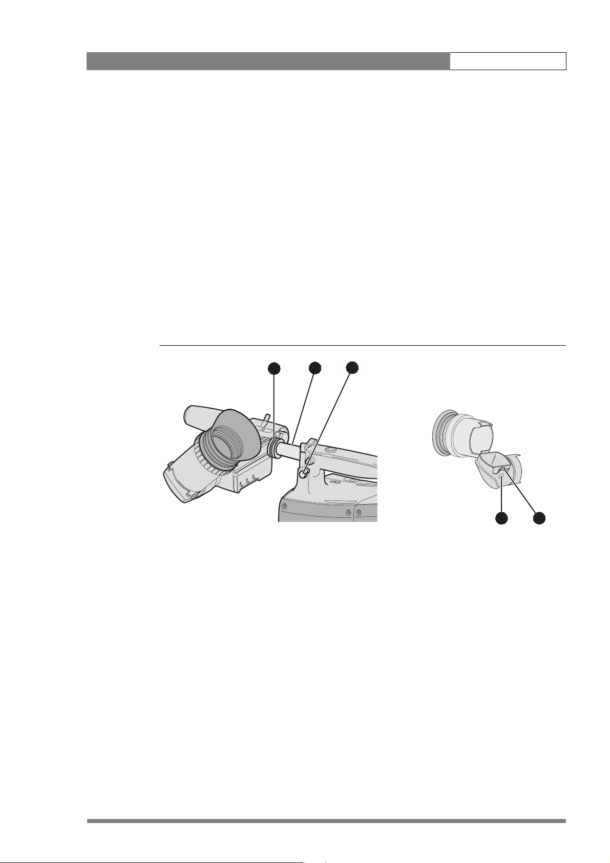
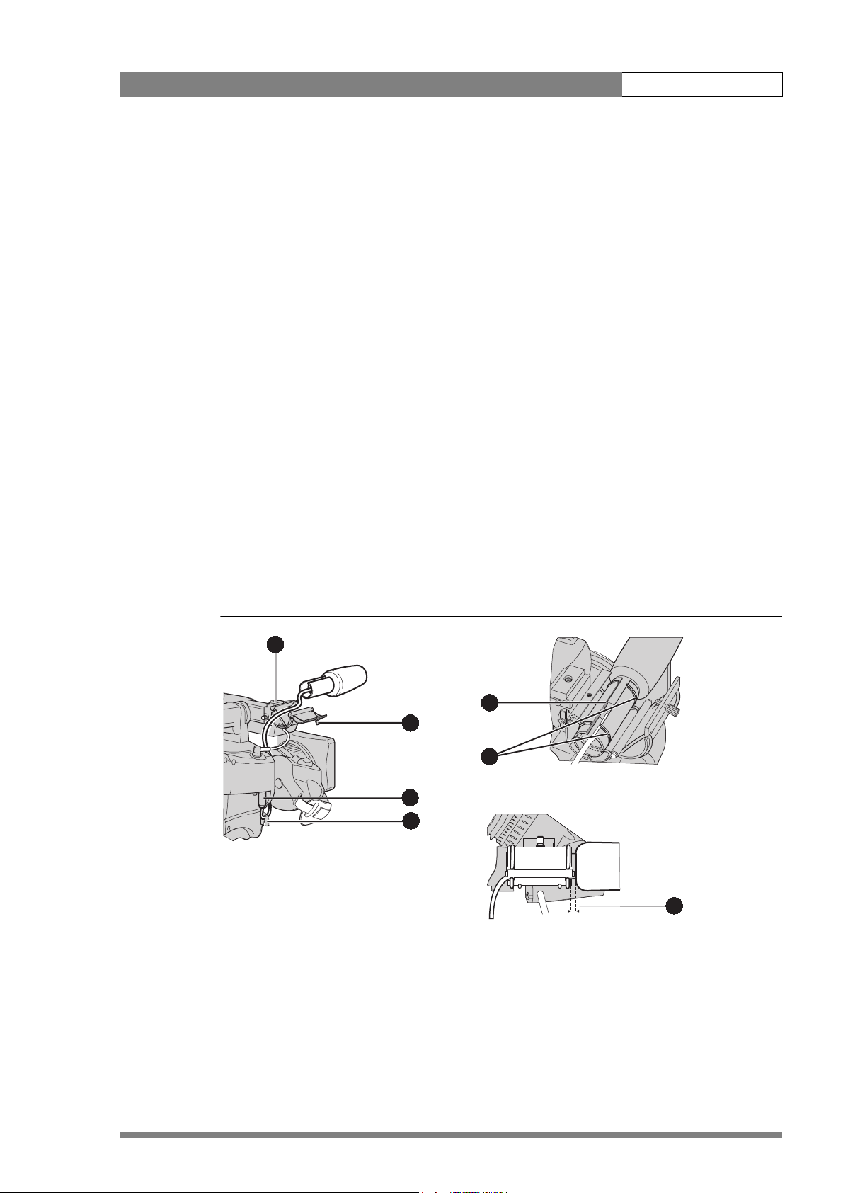
2.4.2 Positioning the viewfinder
The horizontal position of the viewfinder can be adjusted as follows to suit your requirements:
1. Loosen the locking ring (1). (As seen from the rear of the camera, turning the locking ring
counterclockwise moves it towards the handle.)
2. Slide the viewfinder horizontally along the rail to the desired position.
3. Tighten the locking ring (1) by turning clockwise.
The dioptre hood and eyepiece of the viewfinder can be rotated vertically.
The viewfinder can be positioned backwards and forwards along the camera axis. Loosen the
support bracket round bar retaining lever (2) and slide the round bar (3) forwards or backwards.
When the desired position is reached tighten the support bracket round bar retaining lever (2)
again.
To use the viewfinder at a distance press the button (4) below or above the eyepiece tube and
swing it free of the associated clip (5). The display can now be seen from further away.
Figure 2-4. Viewfinder positioning
1
3
2
4
5
v2.0
Page 24
LDK 8000 User’s Guide | Installation 2-6
2.5 Viewfinder accessories
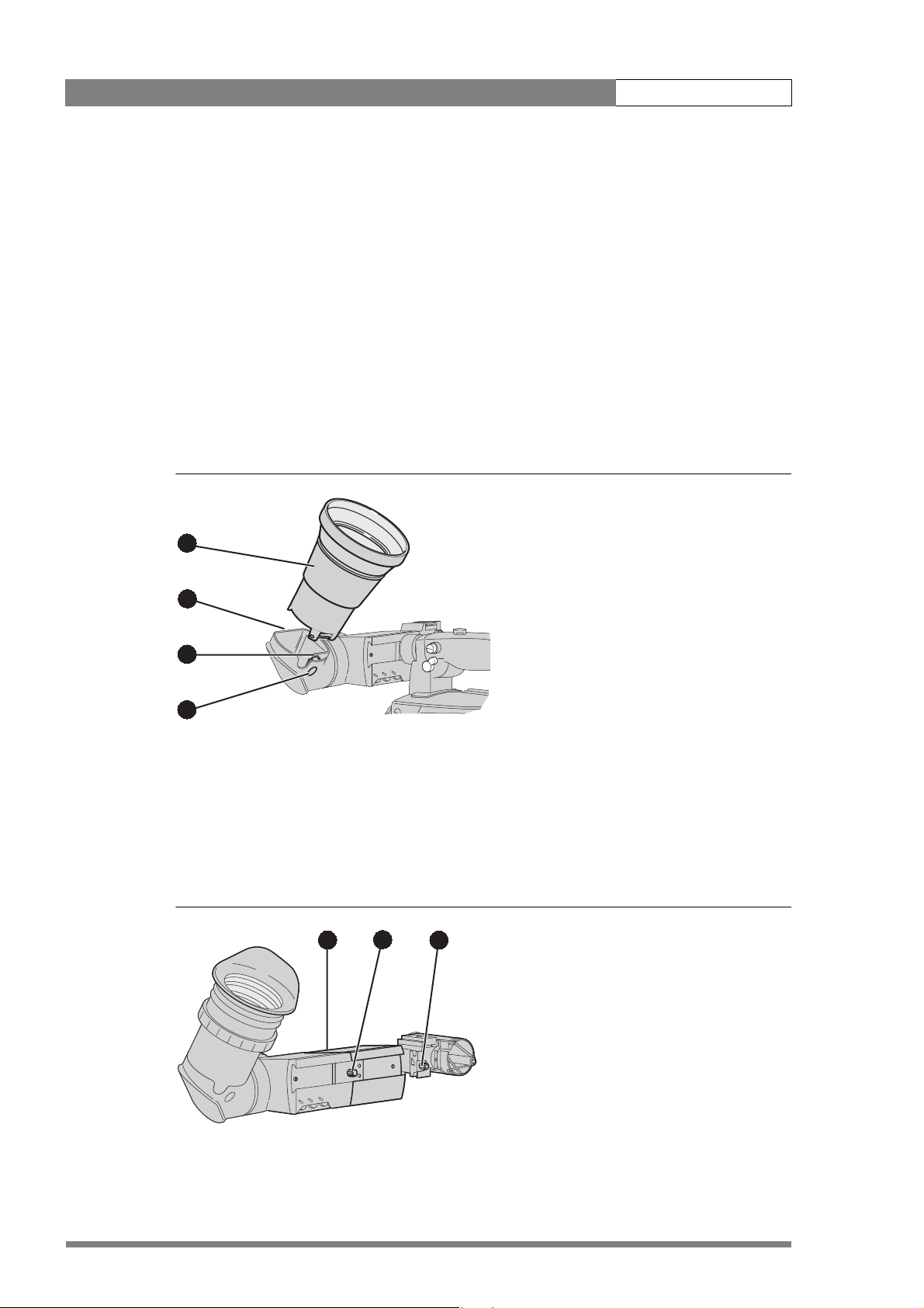
2.5.1 Wide angle eyepiece
If you regularly use the viewfinder at a distance, for example, when you use the camera in the
hand-held position, it is recommended that you fit the optionally available wide angle eyepiece
(LDK 5390/00). To fit the wide angle eyepiece proceed as follows:
1. Hold the eyepiece (1) securely.
2. Press the button (2) below the eyepiece tube and swing it free of the button clip (3).
3. Press the button (4) above the eyepiece tube and remove the eyepiece.
4. Fit the wide angle eyepiece (1) to the two clips (3) ensuring that they both click into place.
Figure 2-5. Viewfinder wide angle eyepiece
1
4
3
2
2.5.2 Left eye adapter
A left eye adapter is optionally available (LDK 5390/10) to allow the viewfinder to be used with
the left eye. Before mounting the viewfinder onto the camera, attach the left eye adapter (1) to
the viewfinder and secure it using the screw (2). Do not forget to mount the microphone
support bracket (3) at the end of the left eye adapter.
Figure 2-6. Viewfinder left eye adapter
1
2
3
v2.0
Page 25
LDK 8000 User’s Guide | Installation 2-7
2.6 Mounting a microphone
To attach the optional microphone (AJ-MC700) to the camera proceed as follows:
1. Open the microphone holder by unscrewing the knurled screw (2) of the microphone
support bracket (1) on the viewfinder and open.
2. Slide the microphone into the split tube until the microphone shoulder reaches the mark
(5) in the tube.
3. Place the tube with the microphone into the holder with the split facing upwards. Mount
the microphone as straight as possible.
4. Ensure that the rubber supports at the back and front of the holder fit into the rims (6)
around the tube.
5. Close the holder and tighten the knurled screw at the top. Don’t allow the wind hood to
touch the holder (7) as this reduces the damping effect.
6. Connect the microphone cable to the MIC audio connector (3) on the right side of the
camera. To avoid mechanical pick-up, do not let the microphone cable touch the holder.
7. Place the microphone cable into the top clip at the front of the camera and into clip (4) at
the side of the camera. (Pull and twist clip to open it.)
Other microphones with a diameter of 21mm can also be used, however, ensure that the
sensitivity of the input that match that type of microphone are correctly selected in the camera
INSTALL menu. When a longer microphone is used, it is not necessary to place it in the split
tube. Phantom power is always present on the front microphone socket.
Figure 2-7. Microphone mounting
1
5
2
6
3
4
7
v2.0
Page 26
LDK 8000 User’s Guide | Installation 2-8
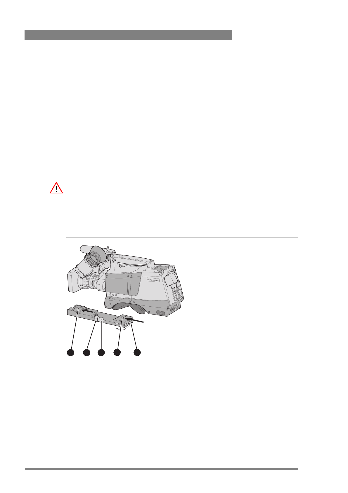
2.7 Tripod adapter plate
To mount the camera on a tripod, the tripod plate LDK 5031/10 must first be attached to the
tripod. Follow the tripod manufacturer’s instructions to mount the wedge plate supplied with
the tripod and the tripod adapter plate firmly onto the tripod. Attach the camera to the tripod
adapter plate as follows:
1. Slide the camera horizontally along the tripod adapter plate from back to front ensuring
that the front of the camera engages the V-slot (1) at the front of the tripod adapter plate,
and that the slot on the bottom of the camera engages the stud (2) at the rear of the tripod
adapter plate.
2. Firmly push the camera forward until it clicks into place.
3. When the camera is mounted firmly, the locking lever (5) swings around fully to the rear
of the plate. If the lever does not travel the full distance, you should manually lock it into
place.
Caution
Failure to attach the camera to the tripod adapter plate in the correct manner could result in an
unsecured camera. Ensure that the rear stud (2) is engaged and that the camera clicks into
place.
Figure 2-8. Tripod adapter plate
2
4
3
1
5
Remove the camera from the tripod as follows:
1. Open the locking lever (5) to free the rear stud (2).
2. Press and hold the red locking lever (3) against the release handle (4).
v2.0
3. Ensure that you have a firm hold of the camera.
4. Pull the release handle (4) forward.
5. Move the camera backwards and up.
Page 27
LDK 8000 User’s Guide | Installation 2-9
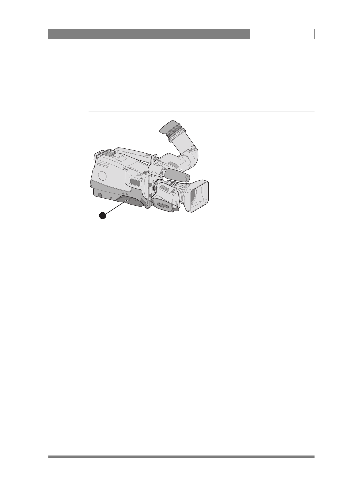
2.8 Adjusting the shoulder pad
To change the position the shoulder pad press and hold lever (1). The shoulder pad can now be
moved backwards and forwards along the axis of the camera. Adjust the shoulder pad when all
units have been mounted to get the best balanced shoulder position.
Figure 2-9. Shoulder pad
1
v2.0
Page 28
LDK 8000 User’s Guide | Installation 2-10
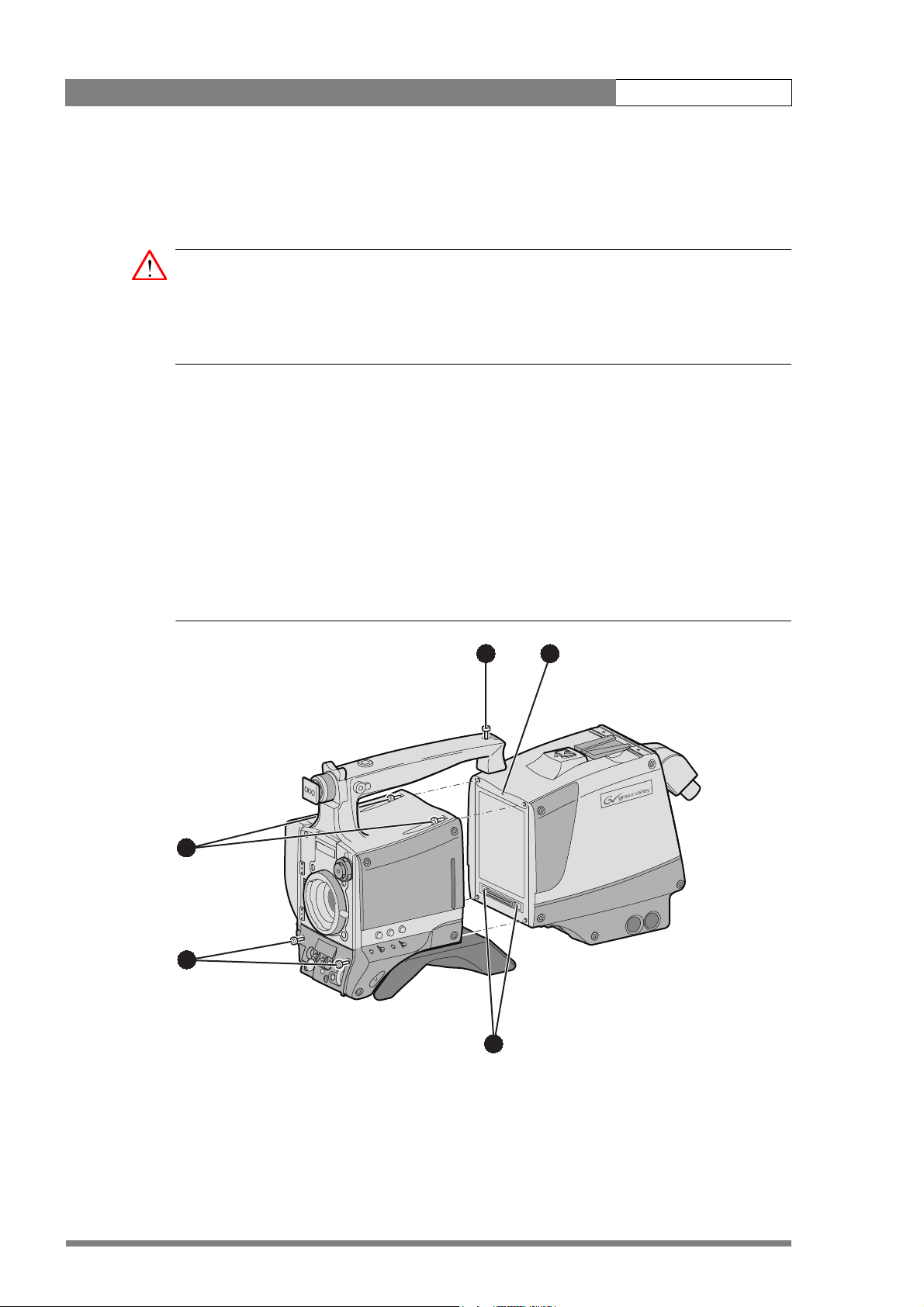
2.9 Attaching an adapter
The camera head is a multi-role camera head that can be used with various adapters.
Caution
Be extremely careful with the connectors between the camera head and the adapter. Do not
allow the guide pins to damage the pins of the connector. Follow these steps in the order
given. Tightening or loosening the screws in the wrong order could result in mechanical
damage to the camera.
To attach an adapter to the camera proceed as follow:
1. Fit the guide pin at the top rear of the camera head and the guide pins on either side of
the camera connector into the corresponding slots (1 and 2) of the adapter.
2. First, tighten the two horizontal screws (3) on the top of camera.
3. Next, tighten the two horizontal screws (4) at the front of the camera.
4. Lastly, tighten the vertical screw (5) in the handle of the camera.
To detach an adapter from the camera head follow the steps for attaching it in the reverse
order.
Figure 2-10. Attaching an adapter
5 1
3
4
v2.0
2
Page 29
LDK 8000 User’s Guide | Configurations 3-1
Chapter 3
Configurations
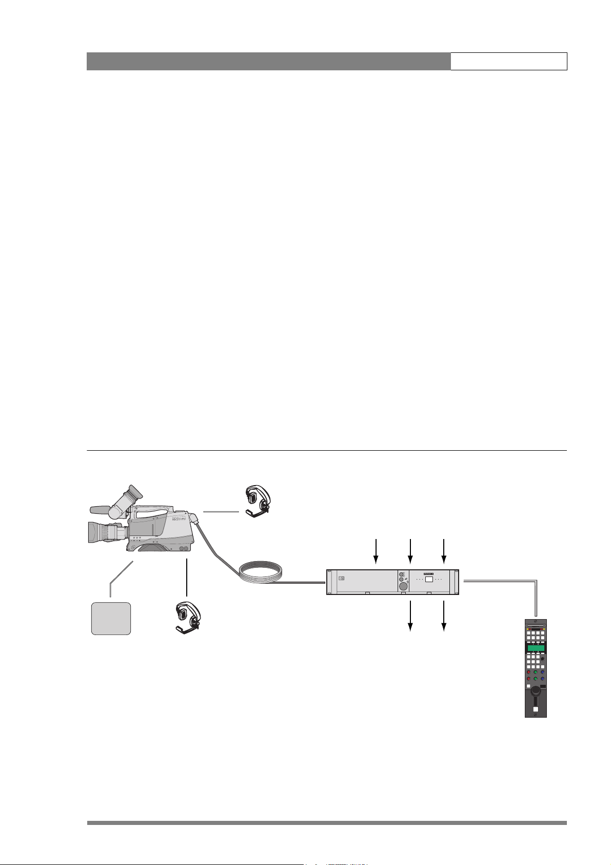
3.1 TriaxHD mode
A camera head with the LDK 5860 TriaxHD adapter is connected to an LDK 4502 HD Base
Station using a Triax cable. The maximum length of cable that can be used without significant
degradation of the video signal is 1,200m (4,000 ft.) for a 14mm Triax cable.
The power supply is applied to the Base Station and via the Triax cable to the camera. An OCP
400 operational control panel can be connected directly to the Base Station using a cross-over
Ethernet cable.
Figure 3-1. Camera in TriaxHD mode
Camera head + Triax adapter
Teleprompter
Tracker
headphone
Camera
operator
headphone
Base Station
TPinExternal
video in
Audio
out
Power
in
Cross over Ethernet cable
Camera Base Station
Video
out
v2.0
OCP 400
Page 30
LDK 8000 User’s Guide | Configurations 3-2
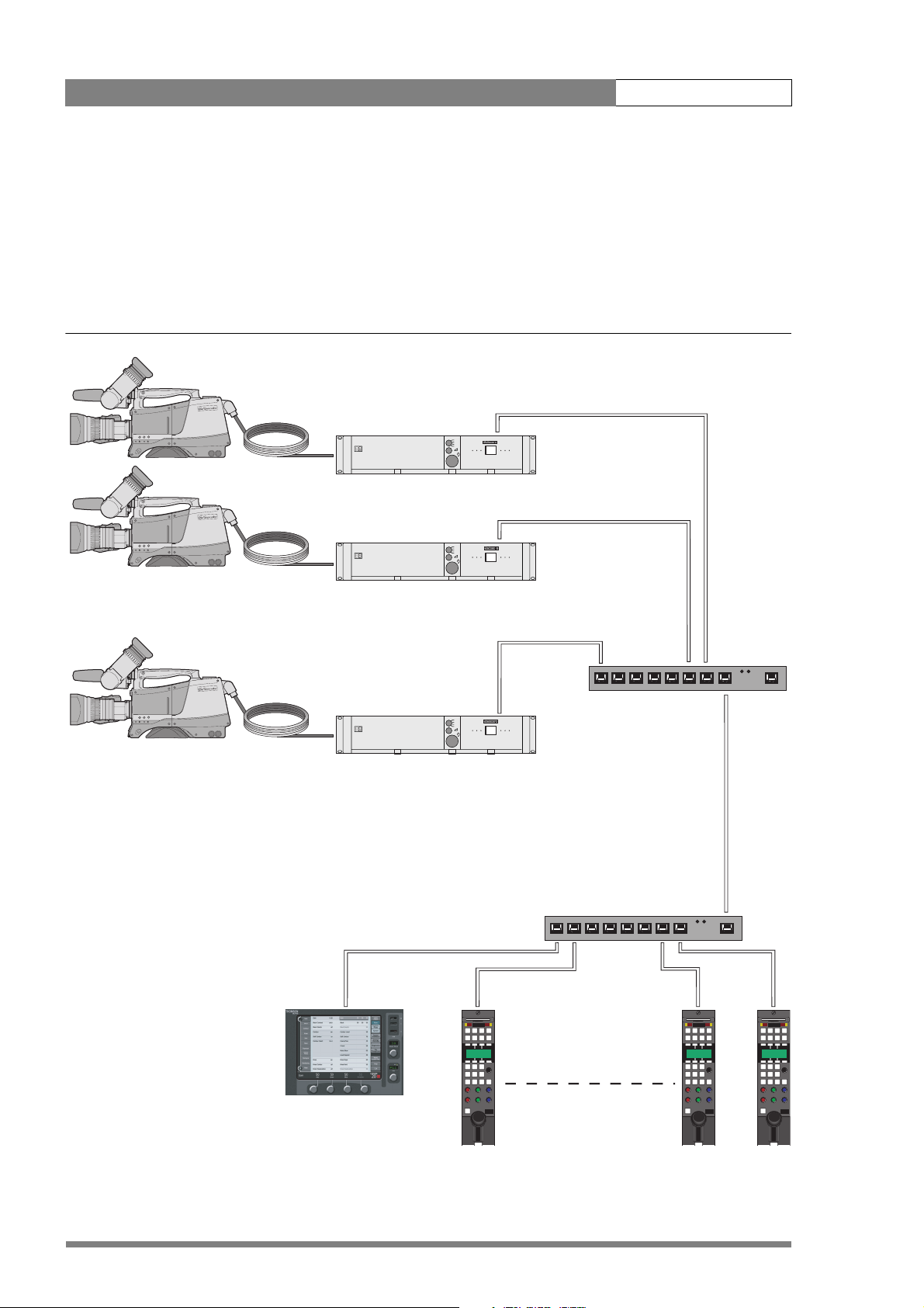
3.2 Multiple TriaxHD cameras with C2IP network
The Base Stations are each connected to a network hub or router via an Ethernet cable
(straight through, not cross-over). The OCP 400 operational control panels and, if required the
MCP 400 Master Control Panel, are also connected to the Ethernet network via a hub or
router.
Figure 3-2. Multiple HD cameras with C2IP network control
Triax adapter
Base Station
Camera Base Station
Ethernet cable
Camera head
Triax cable
Camera Base Station
Hub or switch
Camera Base Station
Hub or switch
Ethernet cable
v2.0
MCP 400
Page 31

LDK 8000 User’s Guide | Configurations 3-3
3.3 Camera with TriaxHD adapter and SuperXpander
A camera head with the LDK 5860 TriaxHD adapter can be mounted in the LDK 4488
SuperXpander. This enables large box lenses to be used with the camera. A 7-inch HDTV
viewfinder LDK 4020/20 can be mounted on the SuperXpander.
The camera with the TriaxHD adapter connects to the SuperXpander via a flying lead. The
power supply for the camera is supplied via this lead. The SuperXpander is connected to an
LDK 4502 HD Base Station using a Triax cable. This configuration can be powered either:
– from the Base Station via the triax cable, or
– locally with the mains power supply connected directly to the SuperXpander.
The maximum length of triax cable that can be used without significant degradation of the
video signal is 1,200m (4,000 ft.) for a 14mm Triax cable when the configuation is powered
locally.
To control the configuration an OCP 400 operational control panel can be connected directly to
the Base Station using a cross-over Ethernet cable. The Base Station is powered by a mains
power supply.
Figure 3-3. Camera with SuperXpander and TriaxHD adapter
Camera head + Triax adapter + SuperXpander
Base Station
TPinExternal
video in
Audio
out
Power
in
Camera Base Station
Cross over
Ethernet cable
Video
out
v2.0
OCP 400
Page 32

LDK 8000 User’s Guide | Configurations 3-4
3.4 Local mode
A camera head with the LDK 5860 TriaxHD adapter can be used in the local mode. The DC
power supply is applied to the adapter. An OCP 400 operational control panel can be
connected directly to the camera using the RS232 connection. A reference signal can be
applied to genlock the camera.
The HD SDI (B) connector carries the HD SDI viewfinder signal. The HD SDI (A) connector
carries the HD SDI camera signal.
Figure 3-4. Camera in local mode
Reference
Camera head +
Triax adapter
in
Video out
RS232
connection
DC power
in
OCP 400
v2.0
Page 33

LDK 8000 User’s Guide | Configurations 3-5
3.5 Triax cable lengths
The approximate maximum cable lengths between a Base Station and a camera are given in
the table below. The signal degrades gradually when these lengths are exceeded. Reduce
these lengths by 20% when a teleprompter signal is sent to the camera.
The maximum length is given for cables of the highest quality. The quality of some cables and
the interconnections can adversely affect this maximum length.
Table 3-1. Triax cable length guide
Cable diameter Maximum length
8mm / 0.32 inch 500 m / 1,600 ft.
11mm / 0.43 inch 700 m / 2,300 ft.
14mm / 0.55 inch 1,200 m / 4,000 ft.
Note
☞
The maximum cable length for 8mm Triax is adversely influenced by the power consumption
of the camera.
v2.0
Page 34

LDK 8000 User’s Guide | Configurations 3-6
v2.0
Page 35

LDK 8000 User’s Guide | Location of controls 4-1
Chapter 4
Location of controls
4.1 Camera head controls and connectors
Figure 4-1. Camera connector location
Viewfinder
connector
connector
v2.0
Lens
HDMI
connector
Microphone
connector
RS232
connector
Page 36

LDK 8000 User’s Guide | Location of controls 4-2
Figure 4-2. Camera head controls - front-left
Clear
1
A
Clear
ND1/4
2
B
Star 4P
ND1/16
3
C
r 6P
Sta
ND1/64
4
D
ocus
t F
Sof
Assignable buttons
Gain switch
Power switch
SW 2
Std.
File
SW1
Standard file button
+
Gain
-
+
Bars
-
Off
Col. Temp.
Off
Black Str.
Black stretch switch
Colour temperature
Power
switch
Colour bars switch
v2.0
Page 37

LDK 8000 User’s Guide | Location of controls 4-3
Figure 4-3. Camera head controls
Zoom control
Tally indicator
Tally indicator
Clear
1
A
ar
le
C
4
/
1
ND
2
B
r 4P
Sta
6
1/1
D
N
3
C
r 6P
ta
S
64
1/
D
N
4
D
cus
o
t F
Sof
Assignable
record button
Audio volume
control
V-shift
switch
VRT start
Audio Level
Exposure
time switch
shift
V
Exp.
Time
White balance
switch
Clean
White
scan
Bal.
Select
Menu
select button
Camera card slot
Clean scan
button
Menu rotary
control
v2.0
Page 38

LDK 8000 User’s Guide | Location of controls 4-4
4.2 TriaxHD adapter controls and connectors
Figure 4-4. TriaxHD adapter controls
Intercom routing switch
Headset production
vol. control selection
Front
Eng
Off
Prod
Rear
Viewfinder display
signal selection
Audio microphone
switches
Video output
selection switch
HD-SDI (B)/VF
Front
Mic.
Mic.
Ext. SD
VF
VF
VF
Loc
Ext1
Mix
Ext2
Ext
Call
Rear
Mic 1
Line
Line
Ext.
HD
Eng Progr Prod
+48V
Headset volume
controls
Call button
Mic 2
Microphone phantom
power switches
+48V
HD-SDI (A)
12V 1.5A max.
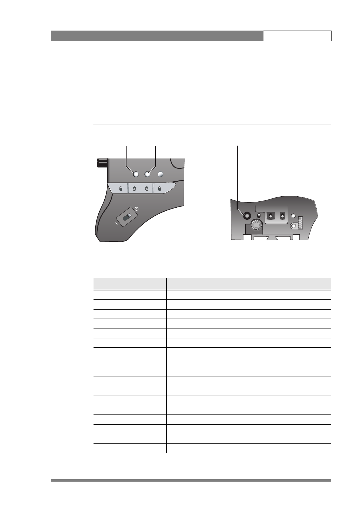
Power on
Script Light
11-17V 5A
Breaker
Power on indicator
Circuit breaker button
v2.0
Page 39

LDK 8000 User’s Guide | Location of controls 4-5
Figure 4-5. TriaxHD adapter connector location
Front
Eng
Off
Prod
Rear
VF
Loc
Ext1
Mix
Ext2
Ext
Triax connector
Viewfinder out
connector
HD-SDI (B) connector
HD-SDI (A) connector
Power out
connector
HD-SDI (B)/VF
HD-SDI (A)
12V 1.5A max.
Front
Rear
Line
Mic.
Line
Mic.
Ext. SD
Ext.
VF
HD
VF
Power on
Script Light
Script light
connector
Call
Mic 1
Mic 2
11-17V 5A
Eng Progr Prod
Microphone 1
connector
+48V
Microphone 2
connector
+48V
Intercom headphone
connector
Breaker
Power in
connector
Reference in / teleprompter out
connector
v2.0
Auxiliary
connector
Tracker
connector
Page 40

LDK 8000 User’s Guide | Location of controls 4-6
4.3 Viewfinder controls and indicators
Figure 4-1. Viewfinder controls
Tally
switch
Dioptre ring
Crispening
control
Figure 4-2. Viewfinder markers and indicators
Gain indicators Top indicators
REC
-
Zoom indication
Cadre marker
Centre marker
Message box
++
+
Zebra
switch
Tally Zebra Option
Crisp
Contr. Bright.
Contrast
control
TAPE
ND/RE
BATT
Option
switch
Brightness
control
FOC+
Iris indicator
Zebra pattern
Safe area
v2.0
4.7
Colour temp.
FL
7.55.63.2
AW2AW1
!
Non-standard
Page 41

LDK 8000 User’s Guide | Operating instructions 5-1
Chapter 5
Operating instructions
5.1 Using the camera
Attach lens, viewfinder, microphone and any other accessories to the camera. Attach the triax
cable or supply the adapter with power.
5.1.1 Switching on the power
1. On the Base Station set the master power switch to the on position (I). The green power
light lights.
2. Set the camera Power switch of the camera to the on position .
3. Allow a few moments for the camera to perform a self-test and for the system to
establish communications.
Note
☞
To switch the camera to stand-by, set the Power switch of the camera to the position.
5.1.2 Controlling the camera
There are several ways of controlling the camera:
• Using an OCP connected to the Base Station.
• Using the switches on the camera itself.
• Using the menu system to select functions.
Note
☞
If you cannot access some camera functions or you wish to restrict access, refer to
Section 5.11 on page 29.
v2.0
Page 42

LDK 8000 User’s Guide | Operating instructions 5-2
5.2 System Menu
The camera is operated via the viewfinder text display and the control system menu switches.
The systems menu is viewed in the viewfinder and navigated by means of the Rotary control
and the Select button which are both located at the front of the camera.
Figure 5-1. Menu control buttons
V
VTR start
shift
Exp.
Time
White
Bal.
Clean
scan
Audio Level
Select
Menu
select button
Menu rotary
control
The functions of the camera are grouped into menus and sub-menus. There are seven
different menus that are listed in the main menu as follows:
VF >>
Lens >>
Video >>
Install >>
Files >>
Security >>
Diagnostics >>
Each of these menus gives you access to a particular group of functions. Spend some time
using the controls and menus to discover the various functions. You will quickly learn to
operate the camera intuitively.
Note
☞
Some of the menu items may not appear if the user level is not set to 3.
5.2.1 Entering the System menu
Press the Select button after the camera is switched on, the message Menu off appears in the
viewfinder. Press the Select button again while this text is showing, the MAIN menu appears
in the viewfinder.
v2.0
Page 43

LDK 8000 User’s Guide | Operating instructions 5-3
Figure 5-2. Main menu
Menu off exec
VF
Lens
Video
Install
MENU: MAIN
Files
Security
Diagnostics
Service
The MAIN menu screen shows five items. The name of the menu is shown below these. Four
more items are hidden but become visible when you scroll down using the Rotary control. A
cursor shows your position in the menu. The Rotary control moves the cursor up and down.
5.2.2 Finding your way
Use the Rotary control to move the cursor through the menu items. If a double arrow (>>) is
visible, then pressing the Select button brings you one level lower in the menu system. Only
five items are visible in each menu. Scroll up or down to see any additional items. When you
first enter a menu (other than the MAIN menu) the cursor is positioned next to the first item.
The TOP and PREVIOUS entries are not immediately visible but are located above the first
item. Use the Rotary control to scroll up to them.
• Select TOP to bring you back to the MAIN menu.
• Select PREVIOUS to go back to the menu that you were in before the current one.
The LENS menu, for example, shows the items displayed when you first enter the menu. The
other items are available by scrolling up or down with the Rotary control.
Figure 5-3. Lens menu
TOP
PREVIOUS
Lens type Std
Auto Iris On
Peak/Average 65
Auto iris setp. 35
Mom. iris setp. 50
MENU: LENS
v2.0
Extended Iris
Page 44

LDK 8000 User’s Guide | Operating instructions 5-4
5.2.3 Leaving the System Menu
If you are deep within the menu structure, the recommended way of leaving the System menu
is:
1. If necessary move the cursor to the left column with the Select button.
2. Scroll upwards with the Rotary control until the cursor points to TOP (this is the MAIN
menu).
3. Press the Select button. The cursor now points to the MENU OFF item of the MAIN
menu.
4. Press the Select button to leave the System menu.
If you do not use the menu it disappears after a few seconds. (This delay can be programmed
in the VF menu.) However, when you press the Select button again you enter the System
menu at the last position of the cursor and not at the top of MAIN menu. To prevent confusion
the next time you enter the System menu, it is advisable to leave the menu by returning to the
MAIN menu (TOP) and selecting MENU OFF.
5.2.4 Making changes
To find out where you have to go to change a function, consult the appendix to discover under
which menu group or sub-group the function you want to change is located. If the cursor
points to an item (and there are no double arrows to indicate a sub-menu) then the item
pointed to has a value. The value can be:
• a toggle value (only two values)
• a list value (more than two values)
• an analogue value (variable from 00 to 99)
• unavailable (---).
If the value is unavailable it cannot be changed. This is indicated by three dashes (---). This can
occur, for example, when a function is switched off. The analogue values associated with that
function are then unavailable.
If there are only two values associated with the function, then pressing the Select button
toggles between these two values. If a value is displayed next to a function that is one of
several possible values, then pressing the Select button places the cursor in a list menu
indicating the value currently selected. Use the Rotary control to point to a new value. Press
the Select button to return the cursor to the function list.
If an analogue value is displayed next to a function name, then pressing the Select button
places the cursor in front of the value and the Rotary control is used to change the analogue
value. Press the Select button to return the cursor to the function list.
5.2.5 Undoing changes
If you make changes to the video settings in the Systems menu and you decide not to keep
them, use the Std. button at the side of the camera to recall a standard set of values for the
video parameters.
v2.0
Page 45
LDK 8000 User’s Guide | Operating instructions 5-5
5.3 Assigning functions to buttons
The camera head has three assignable buttons, two on the side panel (SW1) and (SW2), and
one on the lower front panel (VTR start). The operation of the zoom control button and the VTR
button on the lens can also be assigned. The function and behaviour (momentary or
alternating) of these buttons are set in the INSTALL/BUTTONS menu.
Figure 5-4. Assignable buttons
SW1
button
Power
SW1
SW2
button
SW 2
Std.
Recall
VTR Cam.
button
VTR start
Audio Level
Switch Assignments for Triax operation
SW1 Prod. intercom
Eng. intercom
Zoom
Switch on external signal 1
Switch on external signal 2
SW2 Prod. intercom
Eng. intercom
Zoom
Switch on external signal 1
Switch on external signal 2
VTR Cam. Prod. intercom
Eng. intercom
Zoom
Switch on external signal 1
Switch on external signal 2
VTR lens Prod. intercom
Eng. intercom
shift
V
Exp.
Time
White
Bal.
Clean
scan
Select
v2.0
Page 46

LDK 8000 User’s Guide | Operating instructions 5-6
Switch Assignments for Triax operation
Zoom
Switch on external signal 1
Switch on external signal 2
Zoom switch Momentary
Alternating (latched)
5.4 Video acquisition modes
In the INSTALL menu choose the video mode you wish to use for acquisition. The table below
shows the output signals available for each mode.
5.4.1 Standard camera version
Acquisition format
(sensor)
1080i at 59.94 Hz 1080i59.94 525i59.94 (NTSC) A: 1080i59.94
1080i at 50 Hz 1080i50 626i50 (PAL) A: 1080i50
720p at 59.94 Hz 720p59.94 525i59.94 (NTSC) A: 720p59.94
720p at 50 Hz 720p50 626i50 (PAL) A: 720p50
HDTV
output (B.S.)
SDTV
output (B.S.)
Camera HD-SDI
output
B: VF signal (1080i59.94)
B: VF signal (1080i50)
B: VF signal (720p59.94)
B: VF signal (720p50)
Viewfinder
indication
1080i59
1080i50
720p59
720p50
v2.0
Page 47

LDK 8000 User’s Guide | Operating instructions 5-7
5.4.2 Worldcam version
Acquisition
format (sensor)
1080i at 59.94 Hz 1080i59.94 525i59.94 (NTSC) A: 1080i59.94
1080i at 50 Hz 1080i50 626i50 (PAL) A: 1080i50
1080p at 23.98 Hz 1080psf47.95 colour bar A: 1080psf47.95
1080p at 24 Hz 1080psf48 colour bar A: 1080psf48
1080p at 25 Hz 108psf50 626i50 (PAL) A: 1080psf50
1080p at 29.97 Hz 1080psf59.94 525i59.94 (NTSC) A: 1080psf59.94
720p at 59.94 Hz 720p59.94 525i59.94 (NTSC) A: 720p59.94
720p at 50 Hz 720p50 626i50 (PAL) A: 720p50
720p at 23.98 Hz 720p59.94 525i59.94 (NTSC) A: 720p59.94
720p at 25 Hz 720p50 626i50 (PAL) A: 720p50
720p at 29.97 Hz 720p59.94 525i59.94 (NTSC) A: 720p59.94
HDTV
output (B.S.)
1080psf59.94 525i59.94 (NTSC) A: 1080psf59.94
SDTV
output (B.S.)
Camera SDI
output
B: VF signal
B: VF signal
B: VF signal
B: VF signal
B: VF signal
B: VF signal
B: VF signal
B: VF signal
B: VF signal
B: VF signal
B: VF signal
B: VF signal
Viewfinder
indication
1080i59
1080i50
1080psf23
1080i59-23
1080psf24
1080psf25
1080psf29
720p59
720p50
720p59-23
720p50-25
720p59-29
v2.0
Page 48

LDK 8000 User’s Guide | Operating instructions 5-8
5.5 Viewfinder preferences
Set up the viewfinder according to your own preferences; adjust viewing parameters, select
markers, message boxes and on-screen display times in the VF menu.
Figure 5-5. Viewfinder controls
Dioptre ring
5.5.1 Viewfinder picture quality
Adjust the Brightness and Contrast controls according to your preferences. If you wish, use
the Crispening (peaking) control to adjust the sharpness of the viewfinder picture (reduce
the crispening when the gain is set to +++).
The dioptre of the viewfinder can be adjusted to suit your eyesight by turning the Dioptre ring.
The range of the dioptre is +1 to -3.
5.5.2 Video level indication
Tally
switch
Crispening
control
Zebra
switch
Tally Zebra Option
Crisp
Contr. Bright.
Contrast
control
Option
switch
Brightness
control
Switch on the zebra function so that you are alerted in the viewfinder by a Zebra pattern in
areas where high video levels occur. This diagonal line pattern warns you that the area
affected has risen above a predetermined level of the full scale video exposure value. Go to
the VF menu to set the video levels at which the zebra function works.
5.5.3 Tally indicators
The red Tally indicator at the front of the viewfinder and at the rear of the carrying handle light
to indicate that the camera is on-air. The Tally switch is used to control the Tally indicator at
the front of the viewfinder. When this switch is set to the OFF position, the Tally indicator
does not light when the camera is on-air. The Tally switch does not control the tally indicator
at the rear of the carrying handle.
When the camera is on-air, the REC indicator in the viewfinder lights. When the studio ISO
signal is received, the TAPE indicator lights.
v2.0
Page 49

LDK 8000 User’s Guide | Operating instructions 5-9
Figure 5-6. Viewfinder markers and indicators
Gain indicators Top indicators
TAPE
REC
-
Zoom indication
Cadre marker
Centre marker
Message box
++
+
BATT
ND/RE
FOC+
Iris indicator
Zebra pattern
Safe area
5.5.4 Viewfinder markers
Go to the VF menu to select the markers you wish to see in the viewfinder. The following
markers can be set up:
• The Safe area marker encloses an area that represents 80% of the whole viewfinder
picture area. This is the minimum area seen on a TV-set.
• The Message box displays information messages.The length of time this box remains on
the screen is set by the Info time item of the VF menu.
• The Centre cross marks the centre of the picture.
• The Cadre marker is a dotted white line or a shaded area that shows the limits of a 4:3
(15:9 or 14:9) picture. Exterior marker shading can also be selected.
5.5.5 Focussing
A focus assist function can be switched on or off in the VF menu. This function adds motion in
the viewfinder to objects in sharp focus. The FOC+ indicator in the viewfinder lights when this
function is on.
4.7
Colour temp.
FL
7.55.63.2
AW2AW1
!
Non-standard
v2.0
The viewfinder zoom function is another feature that helps you focus. This function enlarges
the centre of the viewfinder image. Choose one of the following buttons and the way it
operates (momentary or toggle) to control this function in the INSTALL menu:
• The VTR button on the camera,
• The VTR button on the lens,
• The RET switch on a zoom control when a large lens adapter is used.
When the viewfinder zoom function is in use, many of the viewfinder markers are switched off
to improve the clarity of the display. The FOC+ indicator in the viewfinder flashes when the
viewfinder zoom function is active.
Page 50

LDK 8000 User’s Guide | Operating instructions 5-10
5.6 Lens preferences
When you fit a lens to the camera you may need to adjust the back focus. Refer to the lens
manufacturer's instructions to find out how to do this. The LENS menu allows you to choose
and, if necessary, adjust parameters to suit your lens type and your personal preferences.
5.6.1 Lens type
In the LENS menu select the lens type from two predefined settings; standard (Std) or wide
angle (WA). This gives you the optimum shading settings for either a standard or wide angle
lens. The lens manufacturer is also selected in this menu.
5.6.2 Auto iris
If required switch on the auto iris function in the LENS menu. You can also select the
parameters associated with the auto and the momentary iris in this menu.
5.6.3 Extended Iris
The extended iris function automatically regulates the video signal level by adjusting the iris
opening, the gain level and the exposure time to suit the ambient lighting conditions.
To switch on the extended iris function use the Extended iris button at the left-front side of
the camera. When this button is pressed once, the current value of the automatic extended iris
function is displayed. Press the button twice in quick succession to switch between on and
off.
When extended iris is on, the Non-standard indicator in the viewfinder lights, and gain and
exposure controls are blocked. The parameters for the extended iris function are set in the
LENS menu.
5.6.4 Lens indicators
The ND/RE indicator in the viewfinder lights when a lens range extender is selected.
The Iris indicator in the viewfinder shows the value of the iris opening (when enabled in the
VF menu).
The Zoom indicator in the viewfinder shows the degree to which the lens has been zoomed
in or out if this feature is supported by the lens. It shows 50 if not supported.
v2.0
Page 51

LDK 8000 User’s Guide | Operating instructions 5-11
5.7 Video preferences
The means used to control the camera depends on your work methods. A remote OCP can be
used and a low user level can be selected to restrict the available camera functions.
Alternatively, video functions can be controlled on the camera itself. The following functions
are available on the camera:
• Standard settings
• Test signal
• Gain selection
• Optical filter selection
• Colour temperature
• Auto-white balance
• Exposure time
• Black stretch
• Auto skin contour
Many other video functions such as contour, black, gain, knee, gamma, matrix and white limit
functions are available in the VIDEO menu.
5.7.1 Standard settings
To ensure that some of the camera functions are not set to unusual values, a standard file has
been defined that contains the default values for most video functions. The table in the
Appendix lists the values that are set when the standard file is recalled.
To recall the standard values for the various video functions, press the green STD button on
the left-front side of the camera and hold it for two seconds. The standard values only take
effect when the camera is not on-air.
The standard file can be selected as either a factory or a customer standard file. Changing the
standard file can only be done in the System security menu if the owner card or the PIN code
is used.
The Non-standard indicator lights when the video settings are not set to their standard value,
for example, when exposure is not set to nominal. It also lights when black stretch or
extended iris is on and if AWC or FL is selected with the colour temperature selector.
v2.0
Page 52

LDK 8000 User’s Guide | Operating instructions 5-12
Clear
ND1/4
ND1/16
ND1/64
Clear
Star 4P
Star 6P
Soft Focus
12A
B
C
D
3
4
Figure 5-7. Video control buttons
Filter wheel
switches
5.7.2 Test signal
The left-front side panel of the camera has a Colour bars switch for switching on a colour bar
test signal. The colour bar is the standard test signal that is used to set up and check the
camera before use. When the colour bar is selected the following functions are temporarily set
to Off:
• Black stretch
• White limiter
• Zebra
• Safe area (VF)
• Cadre (VF)
SW 2
Std.
File
SW1
Standard file button
+
Gain
-
+
Bars
-
Off
Off
Black Str.
Col. Temp.
Black stretch switch
Colour temperature
Power
switch
Colour bars switch
Gain switch
v2.0
The lens iris closes automatically when the colour bars are switched on.
Page 53

LDK 8000 User’s Guide | Operating instructions 5-13
5.7.3 Gain selection
Depending on the available light levels it may be necessary to adjust the gain of the camera.
The gain is selected via the Gain switch on the left-front side of the camera.
1. When this switch is pressed initially, the current value of the gain in dB is displayed in the
viewfinder.
2. Holding the switch in the up or down position for a very short period selects one of the
five master gain settings: -, 0, +, ++ and +++.
– The actual value of the gain in dB is assigned to these symbols in the INSTALL menu.
– The Gain indicators in the viewfinder light to indicate the value selected. (The + and
++ indicators light when the gain is +++.)
Symbol Gain
- is always -6 or -3dB
0 is always 0dB
+ can be set to 3, 6 or 9dB
++ can be set to 6, 9 or 12dB
+++ is always 12 dB
Variable gain
The gain switch can also be used to vary the gain continuously between its minimum and
maximum value.
1. Hold the switch continuously in the up or down position until you see the value in the
viewfinder change in steps of 0.1dB.
2. Release the switch when you reach the value you want.
3. Using the switch momentarily again sets the gain to the nearest standard value.
5.7.4 Optical filter selection
A neutral density filter and a special effect filter can be placed in the path of the optical signal
to modify the incoming light. The filters are selected via the Filter switches at the top-front of
the camera. These filters can be used, for example, to control depth of field or exposure levels.
The camera does not need colour optical filters to be able to white balance correctly. The range
of the auto-white balance is so wide (from 2.5K to 20K) that there is never any need to use
colour filters to obtain the correct white. Rotate the switches to move the optical filter wheels.
v2.0
Page 54

LDK 8000 User’s Guide | Operating instructions 5-14
The outer (bigger) filter switch has four positions:
Position Filter
1Clear
2 ND 1/4 filter (2 stops)
3 ND 1/16 filter (4 stops)
4 ND 1/64 filter (6 stops)
The inner (smaller) filter switch also has four positions:
Position Filter
1Clear
2 4-point star
3 6-point star
4Soft focus
The status of the filter wheels is displayed in the viewfinder for a few seconds. The ND/RE
indicator in the viewfinder lights when an ND (Neutral Density) filter is selected.
5.7.5 Colour temperature selection
For true colour reproduction the ambient lighting conditions must be compensated for by
selecting a value for the colour temperature. The standard file setting is 3200K (normally used
for tungsten light). Three other reference colour temperatures are available; 4700K (for
outdoors, clouded conditions), 5600K (for outdoors, clouded conditions) and 7500K (for
outdoors, clear blue skies).
The memory positions (FL, FL50, FL60, AW1 and AW2) are available to store the results of the
auto-white measurement process. The memory positions are filled with measured values
using the automatic white balance switch at the front. The FL positions are recommended for
shooting with fluorescent light.
A continuous automatic white balance position (AWC) is also available. This function
continuously measures the white balance and adjusts accordingly. It can be used when a
constant colour balance is required under changing lighting temperatures (sunsets, indoors/
outdoors use).
In the auto-white positions an electronic colour filter can be adjusted in the VIDEO menu. This
varies the colour balance to obtain warmer or colder colour effects. When an automatic white
balance process is performed, the electronic colour filter is reset to its default value.
v2.0
Page 55

LDK 8000 User’s Guide | Operating instructions 5-15
Selecting the colour temperature
The up/down Colour temperature switch on the left-front side of the camera allows a choice
between:
Three preset colour temperatures:
• 3200K (3.2K) - for studio lighting conditions
• 4700K (4.7K) - for outdoors, clouded conditions
• 5600K (5.6K) - for outdoors, clouded conditions
• 7500K (7.5K) - for outdoors, clear blue skies
The memory positions:
• FL - memory position for fluorescent light (matrix automatically set to CoolFL)
• FL50 - memory position for 50Hz fluorescent light (matrix automatically set to CoolFL and
exposure to 50Hz.)
• FL60 - memory position for 60Hz fluorescent light (matrix automatically set to CoolFL and
exposure to 60Hz.)
• AW1 - memory position 1
• AW2 - memory position 2
An automatic continuous white position:
• AWC - continuous measurement (2.5K to 20K)
When the switch is first pressed, the viewfinder displays the current value.
Select a new value by scrolling up or down through the available values.
The Colour temperature indicators in the viewfinder light to show which position is selected.
None of these indicators light when AWC is selected, but the Non-standard indicator lights.
The viewfinder also displays the actual value of a measured colour temperature. The range of
the auto-white balance is from 2.5K to 20K.
Variable colour temperature
The Colour temperature switch on the left-front side of the camera can also be used to vary
the colour temperature continuously between its minimum and maximum value (2.5K to 20K).
1. Hold the switch continuously in the up or down position until you see the value in the
viewfinder change in steps of 10.
2. Release the switch when you reach the value you want.
3. Using the switch momentarily again sets the colour temperature to the nearest standard
value.
v2.0
Page 56

LDK 8000 User’s Guide | Operating instructions 5-16
Auto-white balance
If the reference colour temperatures do not match your lighting conditions carry out the autowhite procedure as follows:
Figure 5-8. Auto white balance switches
SW 2
+
Std.
File
Off
Black Str.
Col. Temp.
Exp.
VTR start
Audio Level
shift
V
Time
White
Bal.
Clean
scan
Select
Auto white balance
switch
SW1
+
Gain
-
Bars
Off
Colour temperature selection
switch
1. Use the Colour temperature switch to select one of the memory positions FL, AW1 or
AW2 in which to store the measured colour temperature value.
2. Press once on the White balance switch at the front of the camera to start the automatic
white balance procedure. The following appears in the viewfinder:
TAPE
REC
++
-
+
BATT
ND/RE
v2.0
AWHITE: window
AW2AW1
FL
☞
7.55.63.2
Note
!
If you did not select one of the memory positions FL, AW1 or AW2, the ’Precondition
fail”message appears in the viewfinder.
3. Point the camera so that the reference white surface is between the two small white
boxes.
Page 57
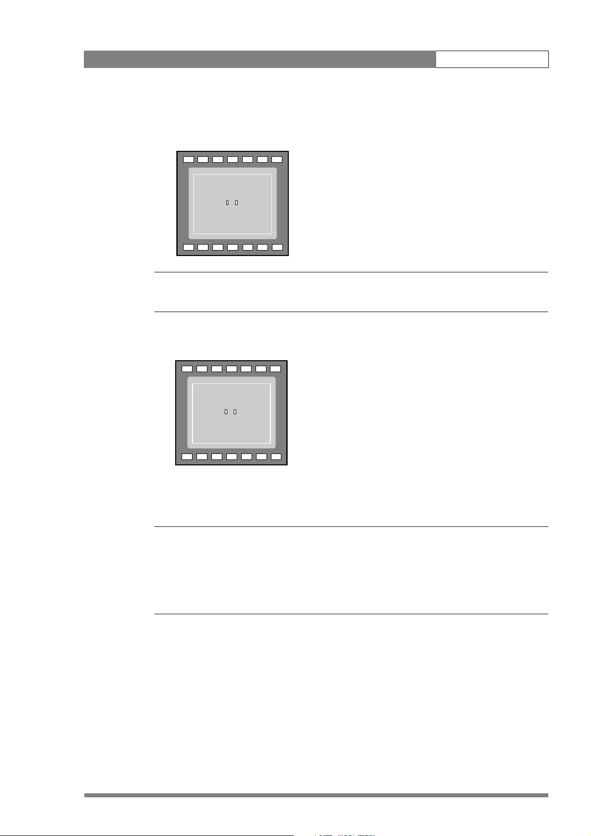
LDK 8000 User’s Guide | Operating instructions 5-17
4. Press the White balance switch again to start the measurement procedure. A message
indicating that the process is runnning appears.
-
+
BATT
ND/RE
TAPE
REC
++
AWHITE: running
AW2AW1
FL
☞
7.55.63.2
Note
!
If there is insufficient light, the ’Light level too low’ message appears in the viewfinder.
5. When the process is completed (within a few seconds) the OK message and the
measured temperature appear in the viewfinder.
-
+
BATT
ND/RE
TAPE
REC
++
AWHITE: OK 3700K
7.55.63.2
!
AW2AW1
FL
The measured colour temperature is now stored in the selected memory position and can be
recalled as required.
Note
☞
During the auto-white measurement process iris is set to Auto and 90% and the knee is turned
off.
Black balance is not necessary with this camera because of the continuous automatic black
control circuits.
v2.0
Page 58

LDK 8000 User’s Guide | Operating instructions 5-18
5.7.6 Exposure time
The exposure time values of 1/200, 1/500 and 1/1000 of a second are used to capture fast
moving objects so that these can be played back sharply in slow motion. The value selected
depends on the speed of the moving object.
Figure 5-9. Exposure time controls
V-shift
switch
VTR start
Audio Level
shift
V
Exp.
Time
Clean scan
button
Clean
White
scan
Bal.
Select
Exposure time
switch
Note
☞
Increasing the exposure speed lowers the camera sensitivity proportionally.
Selecting the exposure time
The momentary up/down Exposure time switch gives a choice of exposure time settings. If
an exposure time other than nominal is selected, the Non-standard indicator (!) in the
viewfinder lights.
v2.0
Valu e Function Shutter blade
Nom. - nominal setting rotating
Var. 1 - enables the exposure to be varied stopped
Var. 2 - enables the exposure to be varied rotating
1/200 - for fast moving objects rotating
1/500 - for fast moving objects rotating
1/1000 - for fast moving objects rotating
50 Hz - shooting with 50Hz lighting (adjustable) rotating
60 Hz - shooting with 60Hz lighting (adjustable) rotating
Lighting
The exposure selection also includes lighting control positions which can be used when
shooting with lighting that is operating at a different frequency to the camera. There are two
positions; 50 Hz and 60 Hz. Each of these positions can be varied further in a range from -10 to
Page 59

LDK 8000 User’s Guide | Operating instructions 5-19
+10. To reduce flicker select the frequency closest to the frequency of the lights and then vary
the lighting control in the INSTALL menu to obtain the best result.
5.7.7 Shooting screens
Sometimes when shooting TVs or computer monitors a horizontal bar can be seen across
these screens in the viewfinder. There are two ways of removing the noise bar from the
picture depending on the frame frequency of the display:
• For displays with the same frame frequency as the camera, for example TV sets, use the
V-shift facility. V-shift can also be used to remove any colour shifts that might occur when
shooting pictures produced by DLP-type devices.
• For displays with a higher frame frequency, for example computer monitors, use the
Clean Scan facility.
Vertical shift (V-shift)
Sometimes when shooting TV screens or monitors with the same display frequency as the
camera, for example TV sets, a horizontal black bar is seen in the viewfinder because the
camera is blanking while the TV is not. The V-shift switch shifts the camera blanking.
The V-shift switch at the front of the camera is spring-loaded with a central rest position.
Holding the switch in the + or - position moves the bar up or down so that it is no longer visible
in the viewfinder. This function is only available when the camera is used in the stand-alone
mode. It is not active when the camera is genlocked or on-air.
When the camera is genlocked, use the V-shift function in the INSTALL menu.
Clean scan
When shooting computer monitors with higher frame frequencies than the camera use the
Clean Scan function as follows to avoid horizontal bars in the picture:
1. Press the Clean Scan button at the front of the camera for about two seconds to directly
access the variable exposure (clean scan) function. The CLEAN SCAN submenu appears in
the viewfinder.
2. Use the Rotary control to change the value and so remove the noise bar.
3. If a more accurate adjustment is required set the CL.SCAN item to EXTENDED. (Set the
mode to NORMAL if a smear effect occurs.)
4. Set the UNIT item to the prefered read out, Hz or mSec.
When you are finished shooting the monitor press the Clean Scan button for two seconds to
switch off the Clean Scan function. (Exposure time returns to its previous non-variable setting.)
When Clean Scan is on, the Non-standard indicator in the viewfinder lights.
v2.0
Note
☞
Do not shoot highlights in the Clean Scan mode as this may cause a smear effect.
Page 60

LDK 8000 User’s Guide | Operating instructions 5-20
Skin
Auto
View
Skin Level
MORE
MENU: VIDEO
1
Off
Off
15
Skin
Auto
View
Skin Level
MORE
MENU: VIDEO
1
Off
Off
15
5.7.8 Black stretch
The black stretch function changes the level of detail in the shadow areas of the picture
without effecting the rest of the picture. Set the Black stretch switch to the On position to
switch on the black stretch function.
The Video menu allows you to adjust the black stretch parameters. Black stretch values above
50 produce more detail in the shadow areas, while values lower that 50 reduce the detail (this
is often referred to as Black Press). The default value is 99.
When black stretch is switched on the Non-standard indicator in the viewfinder lights.
5.7.9 Auto skin contour
Use skin contour to change the contour level in a selected colour range. Decreasing the
contour level of a persons skin colour softens only the skin tones. But not only skin colours can
be selected, for example, decrease the contour level of a soccer field to accentuate the soccer
players or increase the skin contour level to accentuate a rough surface.
Carry out the Auto skin contour procedure as follows:
1. In the VIDEO\SKIN\SKIn menu, select the memory position skin 1 or 2 (not 1+2).
-
+
FL
7.55.63.2
ND/RE
BATT
AW2AW1
!
TAPE
REC
++
2. Place the cursor in front of the VIDEO\SKIN\AUTO item.
TAPE
REC
++
-
+
FL
7.55.63.2
ND/RE
BATT
AW2AW1
!
v2.0
Page 61
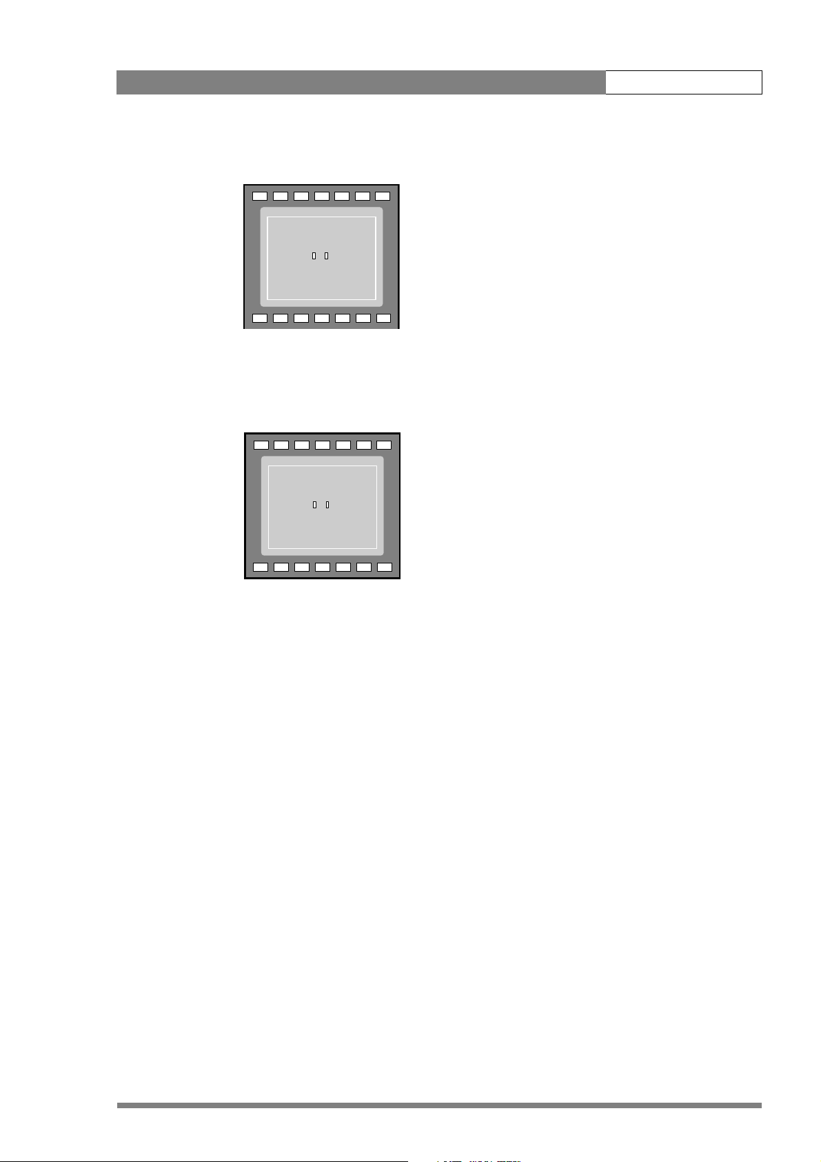
LDK 8000 User’s Guide | Operating instructions 5-21
3. Press the Select button. The following appears in the viewfinder.
-
+
BATT
ND/RE
TAPE
REC
++
ASKIN: window
AW2AW1
FL
7.55.63.2
!
4. Point two small white boxes at the intended surface.
5. Press the Select button to start the measurement procedure (the iris is set to Auto). The
process running message appears:
TAPE
REC
++
-
+
BATT
ND/RE
ASKIN: running
7.55.63.2
!
AW2AW1
FL
6. When the process is completed (within a few seconds) the OK message appears in the
viewfinder.
7. Adjust the skin contour level with the VIDEO\SKIN\SKIN LEVEL item. Decrease the
value below 50 to soften the selected area. Increase the value above 50 to add extra
contour.
Repeat the steps for the other memory position if required. Both skin contour settings can be
used at the same time. Set the menu item VIDEO\SKIN\VIEW to on to indicate the effected
area.
v2.0
Page 62

LDK 8000 User’s Guide | Operating instructions 5-22
5.8 Controls on the TriaxHD adapter
Figure 5-1. Rear controls
Intercom routing switch
Headset production
vol. control selection
Front
Eng
Off
Prod
Rear
Viewfinder display
signal selection
Audio microphone
switches
Video output
selection switch
HD-SDI (B)/VF
Front
Mic.
Mic.
Ext. SD
VF
VF
VF
Loc
Ext1
Mix
Ext2
Ext
Call
Rear
Mic 1
Line
Line
Ext.
HD
Eng Progr Prod
+48V
Headset volume
controls
Call button
Mic 2
Microphone phantom
power switches
+48V
5.8.1 Powering the camera
The power supply for the camera and TriaxHD adapter is normally supplied via the Triax cable
from the Base Station. The power on indicator lights when power is supplied and the camera
power switch is set to the on position .
When power is supplied via the Triax cable, an output power socket supplies +12 Vdc, 1.5A
maximum for powering accessories.
It is also possible to operate the camera without a Triax cable by supplying a +12 Vdc supply to
the DC input socket. The BATT indicator in the viewfinder lights if the camera supply voltage is
less than 11V when using an external supply.
If excessive current flows in the camera or adapter, the circuit breaker trips and shuts off
power to all the units. If this happens check the units for faults and if necessary take corrective
action before pressing the circuit breaker button to reset the power.
HD-SDI (A)
12V 1.5A max.
Power on
Script Light
11-17V 5A
Breaker
Power on indicator
Circuit breaker button
v2.0
Page 63

LDK 8000 User’s Guide | Operating instructions 5-23
E
ff
od
Rear
c.
.
Line
Line
Front
Rea
5.8.2 Selecting monitoring signals
Viewfinder display signal
The viewfinder can display local or external video signals. Two switches determine the signal
that is displayed in the viewfinder. The selection made with these switches also determines
the VF connector output. Viewfinder display signal switch:
– Set to LOC to display the local camera Y signal in the viewfinder.
– Set to MIX to display a mix of the local camera Y signal and external signal.
– Set the switch to EXT to display the external signal 1 or 2.
The external signal selection switch determines which external signal from the Base Station,
either EXT1 or EXT 2, is displayed in the viewfinder.
Figure 5-10. Viewfinder signal display switches
Front
Front
Rear
VF
Loc
Mix
Ext
Viewfinder
display signal
External signal
selection switch
Eng
ng
O
Off
Pr
Prod
Ext1
Ext2
Output monitoring signal
The monitoring output selection switch determines the signal available at the VF output
connector. The output can be switched between:
– VF: the analog viewfinder signal (Y only),
– Ext SD: the external signal from the base station (SD-format, CVBS). or
– Ext HD: the scaled external signal from the base station (HD-format, Y only).
Figure 5-11. VF output connector signal
Front
Rear
r
Line
Mic.
Mi
Line
Mic
VF output connector
signal selection
VF output connector
Mic.
Ext. SD
Ext.
VF
HD
VF
v2.0
Page 64

LDK 8000 User’s Guide | Operating instructions 5-24
5.8.3 Using audio
Two high quality audio channels are available in the Triax mode. Set the gain levels (-22 to -64
dB) for these channels in the AUDIO section of the INSTALL menu. A high-pass filter for each
channel can also be switched on via this menu.
Audio channel 1
The channel 1 input socket selection switch selects either:
• the socket at the front-right of the camera, or
• the Mic 1 audio channel 1 connector at the rear of the adapter
as the input for channel 1.
The rear input level switch selects either a line level input or a microphone level input for the
channel 1 rear connector. The line level input sensitivity is 32dB lower than the microphone
input sensitivity.
The switch under the Mic 1 socket selects a phantom power supply (48V) for the rear socket.
Phantom power (48V) is always present on the front-right microphone socket.
Figure 5-12. Audio channel switches
Channel 1 input socket
selection switch
Front
Rear
Rear input level selection
switch - channel 1
Ch. 2 input level
selection switch
Ch. 2 audio connector
Ch. 2 phantom power
Mic.
Mic.
Ext. SD
VF
Mic 1
Line
Line
Ext.
HD
Mic 2
+48V
Audio channel 1
connector
Channel 1
phantom power
switch
+48V
switch
Audio channel 2
The channel 2 rear input level switch selects either a line level input or a microphone level
input for the channel 2 rear connector (Mic 2). The switch under the Mic 2 socket selects a
phantom power supply (48V) for the rear socket.
v2.0
Page 65
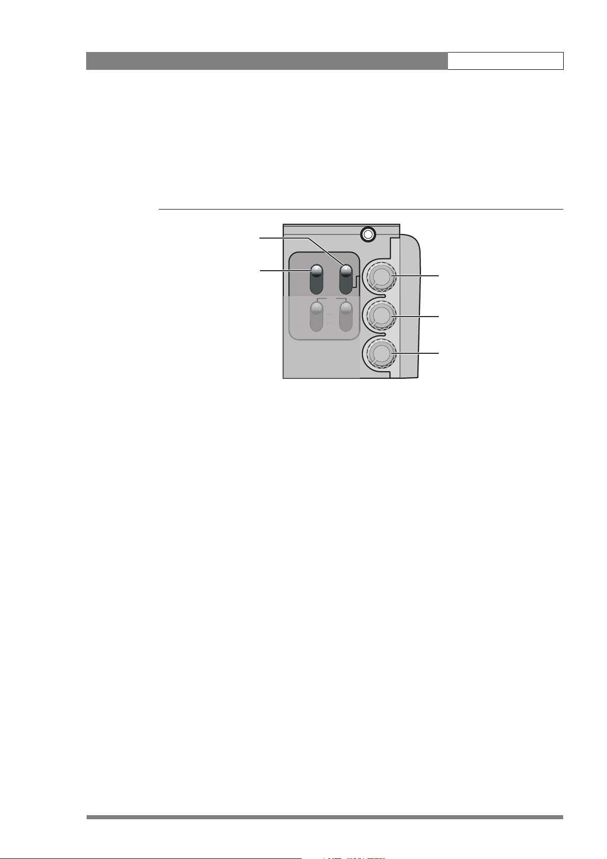
LDK 8000 User’s Guide | Operating instructions 5-25
Ext1
E
L
E
5.8.4 Intercom
Three intercom channels – production (Prod), programme sound (Prog) and engineering (Eng) –
are sent from the Base Station to the camera operator's headset. The camera operator's
intercom microphone signal is sent to the Base Station. Routing and volume controls for the
intercom are on the back of the adapter.
Figure 5-13. Intercom controls
Production intercom
control selection
Front
Intercom microphone
routing switch
Eng
Off
Prod
Ext1
Ext2
Production
Rear
VF
oc
Loc
Mix
xt2
xt
Ext
volume control
Programme
volume control
Eng Progr Prod
Engineering
volume control
Production intercom volume control selection
Use this 2-position switch to control the volume of the production signal in the intercom either
at the front of the camera or at the rear of the adapter.
Intercom microphone routing switch
This 3-position switch routes the camera operator's intercom microphone signal to
engineering (Eng) or production (Prod), or turns it off. The VTR Start button at the front of the
camera, or the VTR button on the lens, can be assigned to send this intercom signal to
production, regardless of the position of this switch.
Intercom headset volume controls
• Prod - adjusts the volume of the production signal to the camera headset when selection
switch is in the REAR position.
• Prog - adjusts the volume of the programme signal to the camera headset.
• Eng - adjusts the volume of the engineering intercom signal to the camera headset.
The INTERCOM section of the INSTALL menu contains various settings for all these channels.
Signals for left and right headset muffs and sidetone levels can be selected. Intercom
microphone amplification levels, phantom power supply and microphone on/off switches are
also available in this menu.
Tracker intercom
A tracker can connect a headset to the side of the adapter to receive the intercom channels
from the Base Station and the camera operator's microphone signal. The tracker's microphone
signal is passed to the camera operator and to the Base Station.
v2.0
Page 66

LDK 8000 User’s Guide | Operating instructions 5-26
5.8.5 Communication
Call button
Press this momentary button to send a signal to the control panels calling for attention. The
ND/RE indicator in the 1.5-inch viewfinder shows when a call signal is sent or received.
The call button can also be used to playback a voice mail message that has been recorded in
the Base Station. Press once to start playback; press again to stop.
Data channel
The Aux connector on the side of the adapter provides analogue control signals and allows for
the connection of a two-way private data channel between camera and Base Station. In the
INSTALL menu, the tracker microphone and engineering intercom channels can be selected
to carry the private data instead of their normal function.
Tracker tally signal
The tracker connector on the side of the adapter, as well as providing full intercom facilities for
the dolly or crane driver, also carries a tally signal and a +12 Vdc power supply. This allows an
external on-air lamp to be used.
v2.0
Page 67

LDK 8000 User’s Guide | Operating instructions 5-27
5.9 Managing files
You can have access to 15 different files. This number can be extended by using additional
scene file camera cards. The Files menu is used to recall and store these files. There are two
types of file:
• scene files
• operator files
A scene file contains values related to the picture performance. The operator file contains
values related to the set-up of the camera (viewfinder, lens and installation parameters). The
tables in the Appendix indicate the functions that are stored in the scene file and those
functions that are stored in an operator file.
5.9.1 Scene files
Four scene files are stored in the camera itself (SCAM1,SCAM2, SCAM3 and SCAM4).
Another four scene files can be stored on the camera card (SCARD1, SCARD2, SCARD3 and
SCARD4). A STANDARD scene file (preselected as either factory or customer defined) is
stored in the camera.
Note
☞
The standard customer scene file is stored via the SECURITY menu, not the FILES menu. The
decision to use the factory defined file or the customer defined file as the standard file is also
made in this menu.
The FILES menu enables the scene files to be stored and recalled using the store and recall
entries of the menu system. If the message NOK is displayed, then the old values are restored.
If the camera is on-air when a scene file is recalled, then the recalled values do not become
active until the camera goes off air.
5.9.2 Operator files
The FILES menu also allows the recall of the operator file stored in the camera (OCAM1) or
one of the two operator files (OCARD1 and OCARD2) stored on the camera card. These files
contain information for setting up the non-video configuration of the camera. A STANDARD
operator files (factory or customer defined) is stored in the camera.
Note
☞
The standard customer operator file is stored via the SECURITY menu, not the FILES menu.
The decision to use the factory defined file or the customer defined file as the standard file is
also made in this menu.
v2.0
Page 68

LDK 8000 User’s Guide | Operating instructions 5-28
5.9.3 Standard files
The green STD button on the left-front side of the camera recalls the standard scene file. This
file contains standard parameters for the picture performance. A standard operator's file can
be recalled via the FILES menu. This file contains parameters for the set-up of the camera.
5.9.4 Customer standard files
You can define a customer standard file for the standard scene file and for the standard
operator's file. The contents of the customer files for both these standard files is stored via the
SECURITY menu. The selection of a factory defined or a customer defined file for use as a
standard file is also made in this menu. You can only access the functions of the SECURITY
menu with an owner's card or the PIN code of the camera.
5.10 User levels
The user level function in the SECURITY menu restricts access, in varying degrees, to the
operational controls of the camera. You can only access the functions of the SECURITY menu
with an owner's card or the PIN code of the camera.
5.10.1 Selecting the user level
There are four user levels: user0, user1, user2 and user3. The purpose of the user levels is to
restrict the set of functions which can be changed by whoever is using the camera. In this way
a more centralized and uniform control can be achieved and the danger of the camera operator
accidentally changing critical functions while shooting is reduced.
User level 0 is a special protection level which locks most of the operational controls of the
camera. Use this level to ensure that a camera that has been set-up is not tampered with. User
level 0 is not normally used for operational purposes as it is too restrictive for normal
circumstances. The recommended minimum user level is 1. For full control set the level to 3.
When you switch off the power, the access rights that were obtained by the use of the PIN
code are disabled and the camera starts at the assigned user level when switched on again.
Disable camera
The disable camera function is a protection function which prevents unathorised interference
with the camera and provides an additional level of security. Setting disable camera to ON is
similar to using User level 0 to protect the settings of the camera.
v2.0
Page 69

LDK 8000 User’s Guide | Operating instructions 5-29
5.11 Access and Security
5.11.1 Camera cards
Three camera cards are delivered with each camera. These comprise of two user's cards and
one owner's card.
Figure 5-14. Camera cards
Owner's Card User's Card
The owner's card has three functions:
• As an access control device to the security settings of the camera.
• As a storage device for four scene files.
• As a storage device for two operator files.
The owner's card is unique to every camera. Owner's card and camera must have the same
serial number. An owner’s card is linked to the serial number of the camera and cannot be
used as an owner’s card for another camera.
The user's card has two functions:
• As a storage device for four scene files.
• As a storage device for two operator files.
Scene files
Both the user's card and the owner's card allow four different scene files to be stored on the
card. The recall and storage of a scene file is carried out via the Files menu of the menu
system. A scene file contains information relating to the video settings.
v2.0
Operator files
Both the user's card and the owner's card allow two different operator files to be stored on the
card. The recall and storage of a operator file is carried out via the Files menu of the menu
system. An operator file contains information relating to the set-up of general camera
preferences.
Page 70

LDK 8000 User’s Guide | Operating instructions 5-30
5.11.2 Access control
The owner’s card or the PIN code is used to access special set-up and security features of the
camera. Inserting the owner’s card into the associated camera always gives direct access to
the Security menu (PIN code is not required). If you select the Security menu without this card
inserted, you must enter the correct PIN code to gain access to this menu.
PIN code
The PIN code of the camera can be viewed and changed in the Security menu. The camera's
PIN code when it leaves the factory is set to 0000. It is strongly advised that this code be
changed by the owner on receipt of the camera. This ensures added protection against
unaurthorised access to the Security menu.
5.11.3 Camera card slot
Insert your camera card into this slot with the chip on the card facing the front of the camera.
Push the card home until it fits snugly. A camera card is not required for normal operation of
the camera.
Figure 5-15. Camera card slot
CAMERA CARD
Note
☞
Only use an original camera card. Store the owner’s card in a safe place.
v2.0
Page 71

LDK 8000 User’s Guide | Operating instructions 5-31
5.12 Smart-Touch™ option
Smart-Touch is an optional software module that gives immediate access to 14 pre-defined
scene files. This library allows you to quickly set up the camera for different shooting
conditions. To choose a particular file proceed as follows:
1. Press the green STD button for 2 seconds; the viewfinder shows the library of available
shooting conditions.
2. Select a file by turning the Rotary control at the front of the camera.
3. Activate the file of your choice by pressing the Select button at the front of the camera.
The new values only take effect when the camera is not on-air. The Smart-Touch files can also
be selected by navigating to the FILES menu using the System Menu. The files of the SmartTouch library are divided into three categories, Lighting, Creative, and Matching, which
complement the standard setting scene file.
The Lighting category provides three different files for various lighting conditions:
• Night optimises the transfer characteristic to enhance the visibility of detail in very dark
scenes without the undesirable consequence of excessive noise associated with simply
increasing gain.
• Fluorescent establishes matrix and colourmetric parameters to reduce the green tinge
and give a more acceptable picture when the scene is lit with uncorrected fluorescent
lighting.
• Extreme contrast uses the full dynamic range of the FT CCD sensor to obtain better
handling of highlights and more detail in the shadows.
The Creative category provides seven files for different effects:
• Sports warm colour delivers warm and rich contrasts bringing out team colours.
• Sports interview incorporates the dual skin tone control into the sports setting for
interviews.
• HI film gives a high contrast film-like look which is ideal for outdoor location production.
• HI film + skin is the HI film setting with dual skin tone control incorporated for natural,
flattering close-ups.
• LO film gives a low contrast film-like look for studio production.
• LO film + skin is the LO film setting with dual skin tone control incorporated for natural,
flattering close-ups.
• Sepia creates a sepia tone look for atmosphere-rich production.
The Matching category provides three files for camera matching:
• LDK9x + LDK10 for matching to Philips LDK9, LDK10, LDK90 and LDK91 cameras.
• DVW xxx for matching to Sony cameras.
v2.0
• HL xxx for matching to Ikegami cameras.
Each of these settings can be personalised and stored on a smart card.
Page 72

LDK 8000 User’s Guide | Operating instructions 5-32
v2.0
Page 73

LDK 8000 User’s Guide | Menu structure and contents 6-1
Chapter 6
Menu structure and contents
6.1 Menu structure
The structure of the main menus and their submenus are shown on the following pages. The
first column shows the user level (0 to 3). You only see menu functions whose user level is
equal to or less than the user level set on your camera. Where appropriate, the default value
of the function in the standard factory file is shown after the function.
6.1.1 Top menu structure
Viewfinder (VF) menu >>
Lens menu >>
Video menu >>
Install menu >>
Files menu >>
Security menu >>
Viewfinder (VF) menu - contains the functions which determine how items in the
viewfinder are displayed.
Lens menu - controls various aspects of the lens.
Video menu - contains those functions which affect the picture quality.
Install menu - contains the functions that are used to set up the general configuration of the
camera. It also contains controls to customize those switches that are directly operated on the
camera.
Files menu - allows values to be stored in scene and operator files, and allows these files to
be recalled as required.
Security menu - used by the camera owner to set user levels and to control access to the
camera, or to store the customer (scene and operator) default files.
Diagnostic menu - provides information on the current status of the camera. No values can
be changed in this menu.
v2.0
Page 74

LDK 8000 User’s Guide | Menu structure and contents 6-2
6.1.2 Viewfinder menu structure
2VF mon Y
2 VF Contour > 2 VF Contour On
0 Focus assist Off 2 Level 50
3Zebra >
0Centre Cross Off
0Audio Bar Off 3Zebra Off
0 Iris Indicator Off 3 Zebra mode Level
0 Focus Indicator Off 3 Zebra level (%) 90
0 Zoom Indicator Off 3 Zebra contrast 15
0 Box downright Off
0 Safe area Off
0 Safe area type 16:9
0 Marker Off
0 Marker type 4:3
0 Marker style Dot
0 Marker shading Shad
0 Indicator White 70
0 Indicator Black 30
0Display Time
0 Menu Time 10
0 Info Time 5
0 Rotary speed 5
0 EXT AspectRatio 4:3
0 LOC AspectRatio 16:9
v2.0
Page 75

LDK 8000 User’s Guide | Menu structure and contents 6-3
6.1.3 Lens menu structure
0 Lens Type STD
0 AutoIris Off
3 Peak/Average 65
3 AutoIris Setpoint 35
3 Mom.Iris Setpoint 35
0 Manufacturer Fuji
0 RE Iris comp. Off
3 Extended Iris > 3 Min Iris F16
3 Autoiris const > 3 Max Iris F2
3 Min Exp.Time 1/500
3 Max Gain (dB) 15
3 Iris gain 5
v2.0
Page 76
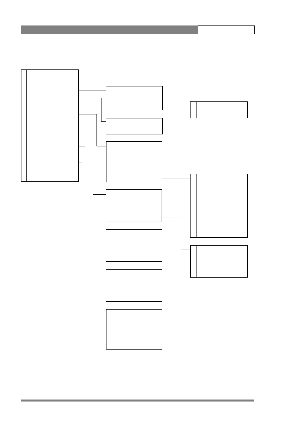
LDK 8000 User’s Guide | Menu structure and contents 6-4
6.1.4 Video menu structure
2 Colour Filter 50
2 Contour Level 30
3 Contour > 3 Level 50
2 Soft Contour > 3 Source Select R+G
3 Knee Contour Off 3 <more> > 3 vert cont 50
2Skin > 3coarse/fine 5
2 Black > 2 Soft Contour On
2 Gain > 2 Level 70
2Knee Off
3Knee > 2Skin Off
2 Gamma Nom 2 Auto Off
3 Gamma > 2 View Off
3 Matrix Skin 2 Skin Level 50
0 Saturation 50 3 <more> > 3 width1 Red 50
3 width1 Blue 50
2 Dyn Black - 3 color1 Red 50
3 Blackstretch 99 3 color1 Blue 50
2 Master 50 3 width2 Red 50
3 <more> > 3 width2 Blue 50
3 color2 Red 50
2 Red 50 3 color2 Blue 50
2Green 50
2Blue 50 3Red 50
2 Range 3db 3 Green 50
3Blue 50
3Knee Off 3Master 50
3 Knee Type Y
3 Slope M 60
3Point M 50
v2.0
3 Gamma Nom
3Master 76
3Red 76
3Green 76
3Blue 76
Page 77

LDK 8000 User’s Guide | Menu structure and contents 6-5
6.1.5 Install menu structure (HDriax)
3 Videomode
2 HD Aspect Ratio 16:9
0 Disable camera Off
0IR receiver Off
0 Tally Handgrip (2”) On
0 OnAir Lamp (7”) On
1 Intercom > 1 SideTone 50
1 Audio > 1 Cam.Mic Sw.
3 Notch Off 1 Cam.Mic gain 40dB
1 Exposure > 1 Cam.Mic power Off
2 Gain preset > 1 Cam.Production Both
0 Timing > 1 Cam.Engeneering Both
1 Quick Smart Touch On 1 Cam.Program Both
0 Private Data Off 1 Cam.Track Off
3 Fan operation > 1 Cam.Track level 50
1 Track Mic to Off
1 Track Mic gain 40dB
1 Track Mic Power Off
1 Track Source Side
1 Cam. Mic to CH1
1 Audio1 Gain -22dB
1 Audio1 HPF Off
1 Audio2 Gain -22dB
1 Audio2 HPF Off
1 Lighting 0
1 Clean Scan > 1 Cl. Scan Mode Norm.
1 Value 50/60
2 gain - -3dB 1 Units Hz
2 gain + 3dB
2 gain ++ 6dB
0 H.Phase 50
0 V-shift Off
0 V-shift level -
3 Head fan On
3Adapter fan On
v2.0
Page 78

LDK 8000 User’s Guide | Menu structure and contents 6-6
6.1.6 File menu structure
2 Store Scenefile > 2 file select
1 Recall Scenefile > 2 store
1 Store Oper.file >
Recall Oper.file > 1 file select
Attributes > 1 recall
2 Standard Files >
1file select
1store
1file select
1 recall
2file select
2file name
2 attribute
2 Standard Settings
(Lighting)
2Night
2 Fluorescent
2 Extreme Contrast
(Creative)
2 Sport Warm Color
2 Sport Interview
2HI Film
2 HI Film + Skin
2 LO Film
2 LO Film + Skin
2 Sepia Film
(Matching)
2LDK9x + LDK10
2DVW-xxx
2 HL-xxx
2 Standard Settings
v2.0
Page 79

LDK 8000 User’s Guide | Menu structure and contents 6-7
6.1.7 Security menu structure
2 Installed Level user3
2 Run Hours > 2 days ago
0 PIN code 0000 2 set time > 2 Hour -
0 Customer Files > 2 set date > 2 Minute -
0 Green Button >
0 Store Cust.Scene exec 2 Year -
0 Store Cust.Oper exec 2 Month -
2 Day -
0 Standard Fact
0 Scene File On
0 Operator File On
v2.0
Page 80

LDK 8000 User’s Guide | Menu structure and contents 6-8
6.2 Menu contents
The number (0,1, 2 or 3) in the LEVEL column indicates the user level at which this item is
visible in the menu; items with numbers higher than the user level that is set on the camera
are not visible in the menu. For example, if user level 2 is set, items marked with a 3 are not
visible.
• If an item is not relevant it is not visible in the menu.
• The Sc. in the FILE column indicates that the value of this item is stored in the Scene file;
the Op. indicates that the value of this item is stored in the Operator file.
• In the VALUES column, the default value of the item is shown in bold.
Note
☞
The items available in the camera menu depend on the version of the software loaded in your
camera. The software version used to reproduce the menu items in this manual may differ
from that of your camera.
6.2.1 Viewfinder menu contents
MENU VALUES DESCRIPTION LEVEL FILE
VF Mon Y, R, G, B, -G Select signal to view in viewfinder. 2 Op.
VF Contour
VF Contour On, Off Turn contours for viewfinder signal on or off. 2 Op.
Level 0..99 (50) Set contour level for viewfinder signal. 2 Op.
Focus Assist On, Off Adds crawling effect in focused areas in the VF.
Zebra Zebra is a diagonal line pattern that warns you
Zebra On, Off Turn zebra indication on or off.
Zebra mode Level, Band Level: zebra indication appears in all
Zebra level (%) 0..99 (90) Set the exposure level where zebra indication is
Zebra contrast 0..99 (15) Set the zebra indication contrast. 3 Op.
Centre Cross On, Off The Centre marker cross marks the centre of
Iris Ind. (SuperXpander) On, Off F stop number is displayed in VF 0 Op.
Focus Ind. On, Off Lens focus position indication:
Zoom Ind. On, Off Zoom position indication, if supported by lens: 0
Box Downright Time, Battery, Tape, FLTR,
Off
that the area affected has risen above a
predetermined level of the full scale video
exposure value.
overexposed picture areas.
Band: zebra indication appears between two
specified exposure levels.
on.
the picture.
0 = close-up, 99 = infinity
= wide, 99 = tele
Select the type of information you want to see
in the message box.
3 Op.
3Op.
0Op.
0Op.
0 Op.
0Op.
v2.0
Page 81

LDK 8000 User’s Guide | Menu structure and contents 6-9
MENU VALUES DESCRIPTION LEVEL FILE
Safe area On, Off The safe area indicates an area that represents
80% of the whole viewfinder picture area.
Safe area type 16:9, 15:9, 14:9, 4:3 Set the aspect ratio of the safe area marker. 0 Op.
Marker On, Off Turn on to show the used area limits. 0 Op.
Marker type 15:9, 14:9, 4:3 Set the aspect ratio of the used area marker. 0 Op.
Marker style Dot, Shad, Both Set the style of the used area marker. 0 Op.
Marker shading Shad, Black Set the shading of the used area marker. 0 Op.
Ind. White 0..99 (70) Adjust the contrast of the characters. 2 Op.
Ind. Black 0..99 (30) Adjust the black shading of the characters; 0 =
Display On, Time (reset on power
up)
Menu Time 0..10 (10) Set the length of time the menu is displayed
Info Time 0..20 (5) Set the length of time that pop-up messages
Rotary speed 0..10 (5) Adjust the sensitivity of the rotary control
EXT AspectRatio 4:3, 16:9 Aspect ratio converter for external video
LOC AspectRatio 4:3, 16:9 Aspect ratio when the SD 5-inch viewfinder is
black, 99 = no shading.
Select the menu display to be on all the time or
to disappear after a set time.
when set to Time.
are displayed.
wheel.
displayed in VF.
used (only with modification).
0 Op.
2Op.
2 Op.
3Op.
3 Op.
3Op.
0
0
v2.0
Page 82

LDK 8000 User’s Guide | Menu structure and contents 6-10
6.2.2 Lens menu contents
MENU VALUES DESCRIPTION LEVEL FILE
Lens Type STD, WA Select a standard (STD) or wide angle (WA) type
lens (affects white shading compensation).
AutoIris On, Off Turns On / Off Auto Iris 0
Peak/Average 0..99 (65) Auto iris setting, balance between peak and
average video level values.
Auto Iris Setpoint 0..99 (35) Auto Iris exposure level setting 3 Sc.
Mom. Iris Setpoint 0..99 (35) Exposure setting in the central area. Exposed to
70% at setting = 50.
Manufacturer Ang, Fuj, Ang, Can, Other Select the manufacturer of the lens (Angenieux,
Canon, Fujinon or other) to compensate for
differences in iris servo feedback.
RE Iris comp. On, Off Turn on to compensate for iris loss when the
lens Range Extender is turned on.
Extended Iris Automatically regulates the video level by
adjusting the iris opening, the gain level and the
exposure time to suit the ambient lighting
conditions.
Min Iris F5.6, F8, F11, F16 Set the minimum iris value to be used with the
extended iris function.
Max Iris F1.4, F2.0, F2.8, F4.0, F5.6 Set the maximum iris value to be used with the
extended iris function.
Min Exp. Time 1/100..1/500 Set the minimum exposure time to be used
with the extended iris function.
Max Gain (dB) 0..15 dB Set the maximum gain value to be used with
the extended iris function.
AutoIris const
Iris gain 5..10 Set sensitivity of auto iris: 5 = slow response,
10 = fast response
0Op.
3Sc.
3Sc.
0
0
3Op.
3 Op.
3Op.
3 Op.
3
v2.0
Page 83

LDK 8000 User’s Guide | Menu structure and contents 6-11
6.2.3 Video menu contents
MENU VALUES DESCRIPTION LEVEL FILE
Colour Filter 0..99 (50) This electronic colour filter varies the colour
balance to obtain warmer or colder effects for
the auto-white memory positions. It resets to
50 when the next automatic white balance
process is carried out.
Contour Level 0..99 (30) Set contour enhancement level. 2 Sc.
Contour
Level 0..99 (50) Set contour enhancement level. 3 Sc.
Source select Y, R, G, R+G Select source to be used for contour
generation: Y before knee, R, G, or average of
R+G.
vert cont 0..99 (50) Adjust the level of vertical component in the
contour signal.
coarse/fine 0..99 (5) Adjust the coarseness of the contours (0 is very
fine).
Soft Contour
Soft Contour Off, On Set to On to reduce the amount of contour
added for large transitions.
Level 0..99 (70) Adjust the upper limit level of contour
enhancement for soft contours.
Knee Contour Off, 1, 2, 3, 4 Select a level of contour enhancement for the
compressed signal above the knee (4 is high
level of enhancement).
Skin Use skin contour to change the contour level
within a selected colour range.
Skin Off, 1, 2, 1+2 Turns on skin contour and selects the memory
position.
Auto Off, On Select to take a sample of the skin colour. 2 -
View Off, On Set to on to indicate the selected area. 2 -
Skin Level 0..99 (15) Decrease the skin contour level below 50 to
soften the selected area. Increase the value
above 50 to add extra contour.
<more>
width1 Red 0..99 (50) Manual correction of skin gate (red saturation)
for memory position 1.
The higher the number, the broader the range.
width1 Blue 0..99 (50) Manual correction of skin gate (blue saturation)
for memory position 1.
color1 Red 0..99 (50) Manual correction of skin gate (red color) for
memory position 1.
color1 Blue 0..99 (50) Manual correction of skin gate (blue color) for
memory position 1.
width2 Red 0..99 (50) Manual correction of skin gate (red saturation)
for memory position 2.
width2 Blue 0..99 (50) Manual correction of skin gate (blue saturation)
for memory position 2.
2Sc.
3Sc.
3 Sc.
3Sc.
2Sc.
2 Sc.
3Sc.
2Sc.
2 Sc.
3 Sc.
3Sc.
3 Sc.
3Sc.
3 Sc.
3Sc.
v2.0
Page 84

LDK 8000 User’s Guide | Menu structure and contents 6-12
MENU VALUES DESCRIPTION LEVEL FILE
color2 Red 0..99 (50) Manual correction of skin gate (red color) for
memory position 2.
color2 Blue 0..99 (50) Manual correction of skin gate (blue color) for
Black
Blackstretch 0..99 (99) Set black stretch level (50 is no stretch, values
Master 0..99 (50) Black level adjustment – RGB 2 Sc.
<more> 3
Red 0..99 (50) Black level adjustment – R 3 Sc.
Green 0..99 (50) Black level adjustment – G 3 Sc.
Blue 0..99 (50) Black level adjustment – B 3 Sc.
Master 0..99 (50) Black level adjustment – RGB 3 Sc.
Gain
Red 0..99 (50) Manual red gain control 2 Sc.
Green 0..99 (50) Manual green gain control 2 Sc.
Blue 0..99 (50) Manual blue gain control 2 Sc.
Range 3dB, 6dB Gain control step size 2 Op.
Knee Off, Auto, Var Knee Off, Auto, or variable (manual) 2 Sc.
Knee -
Knee Off, Auto, Var Knee Off, Auto, or variable (manual) 3 Sc.
Knee Type Y, NAM Signal used for knee. (NAM: luminance of
Slope M 0..99 (60) Adjusts the knee slope angle in manual mode 3 Sc.
Point M 0..99 (50) Adjusts the knee slope point in manual mode 3 Sc.
Gamma Nom, Low, Pre Select Normal, Low (linearised on each selected
Gamma
Gamma Nom, Low, Pre Select Normal, Low (linearised on each selected
Master 0..99 (76) Adjust the RGB gamma curves manually. 3 Sc.
Red 0..99 (76) Adjust the red gamma curve manually. 3 Sc.
Green 0..99 (76) Adjust the green gamma curve manually. 3 Sc.
Blue 0..99 (76) Adjust the blue gamma curve manually. 3 Sc.
Matrix EBU, Skin, B/W, RAI, BBC,
1:1, CoolFL
Saturation 0..99 (50) Adjust saturation 0 Sc.
memory position 2.
below 50 are black press)
highest RGB component)
curve) or Pre (manual curve).
curve) or Pre (manual curve).
EBU: True colour matrix.
SKIN: Optimised for skin tone reproduction.
B/W: Monochrome picture
RAI: SONY cameras impression.
BBC: BBC optimisation.
1:1: Matrix is off.
COOLFL: Optimised for mixed fluorescent and
incandescent lighting.
3 Sc.
3Sc.
3Sc.
3 Sc.
2Sc.
3Sc.
3 Sc.
v2.0
Page 85

LDK 8000 User’s Guide | Menu structure and contents 6-13
6.2.4 Install menu contents
MENU VALUES DESCRIPTION LEVEL FILE
Video mode Available modes (1080i59) Select a video acquisition mode (Available
modes depend on the camera version. See
Section 5.4 on page 6).
HD Aspect Ratio 16:9, Wide Select the aspect ratio. 2
IR receiver Off, On Enable or disable the remote control IR receiver
on the camera.
Tally Hand grip (2”) On, Switch Set to On so that the tally light at the rear of the
hand grip follows the tally signal; set to Switch
to allow it to be switched off with the switch on
the 2” viewfinder.
On-air Lamp (7”) Off, On Set to On so that the tally light at the front of
the 7” viewfinder follows the tally signal; set to
Off if you never want it to light.
Intercom
SideTone 0..99 (50) Set the level of the sidetone in the camera
Cam.Mic Off, On, Switch Set to Switch to allow the intercom routing
Cam.Mic gain 0dB, 40dB Set gain of camera operator’s intercom
Cam.Mic power Off, On +48V phantom power to camera operator’s
Cam.Production Off, Left, Right, Both Select the camera operator’s ear muff for the
Cam.Engeneering Off, Left, Right, Both Select the camera operator’s ear muff for the
Cam.Program Off, Left, Right, Both Select the camera operator’s ear muff for the
Cam.Track Off, Left, Right, Both Select the camera operator’s ear muff for the
Cam.Track level 0..99 (50) Set the level of the tracker signal in the camera
Track Mic to Off, Cam, Eng, Prod, All Select the tracker microphone routing. 1 Op.
Track Mic gain 0dB, 40dB Set gain of tracker’s microphone to 0dB or 40dB 1 Op.
Track Mic Power On, Off +48V phantom power to tracker’s microphone 1 Op.
Track Source Side, Eng Select engineering intercom or tracker’s
Cam. Mic to CH1, CH2 1 Op.
Audio 1Op.
Audio1 Gain -22dB, -28dB, -34dB,
-40dB, -46dB, -52dB,
-58dB, -64dB
+6db, 0dB, -6dB, -12dB, 18dB, -24dB, -30dB, -34dB
operator’s headphones.
switch on the adapter to route the intercom
microphone signal.
microphone to 0dB or 40dB.
intercom microphone.
production intercom.
engineering intercom.
program audio.
tracker intercom.
operator’s headphones
microphone sidetone for tracker’s headphone.
Set gain of Audio 1 channel for mic. input.
Set gain of Audio 1 channel for line input.
3-
0Op.
0
0Op.
1Op.
1 Op.
1Op.
1 Op.
1Op.
1 Op.
1Op.
1 Op.
1Op.
1Op.
1 Op.
v2.0
Page 86

LDK 8000 User’s Guide | Menu structure and contents 6-14
MENU VALUES DESCRIPTION LEVEL FILE
Audio1 HPF On, Off Turn Audio1 high-pass filter on to reduce 50Hz.
hum or low freqency noise.
Audio2 Gain -22dB, -28dB, -34dB,
-40dB, -46dB, -52dB,
-58dB, -64dB
+6db, 0dB, -6dB, -12dB, 18dB, -24dB, -30dB, -34dB
Audio2 HPF On, Off Turn Audio 2 high-pass filter on to reduce 50Hz.
Notch On, Off Turn CVBS notch filter on or off. 3 Op.
Exposure
Lighting -10 . . . +10 (0) Select correction in 50 / 60Hz mode to
Clean Scan
Cl. Scan Mode Normal, Extended In normal mode the shutter blade is running (no
Value 50.6 … 103.1Hz (50)
54.7 … 121.5Hz (60)
Units Hz, msec Select display units for clean scan. 1
Gain preset
gain - -6dB, -3dB Select gain value for - preset position. 2 Op.
gain + +3dB, +6dB, +9dB Select gain value for + preset position. 2 Op.
gain ++ +6dB, +9dB, +12dB Select gain value for ++ preset position. 2 Op.
gain +++ +12dB, +15dB Select gain value for +++ preset position. 2 Op.
Timing
H.Phase 0..99 (50) Adjust CVBS H-phase. 0 Op.
V-shift Off, On Set to On to synchronize camera with DLP
V-shift level 0..99 Variable video delay from 0 to 1 frame. 0
Quick Smart Touch On, Off When On, green STD button opens Smart
Private Data Off, C->B, B->C, B<->C Select the purpose of the tracker intercom
Fan operation
Head fan On, Off Turns the head fan off. Turns itself on after 2
Adapter fan On, Off Turns the adapter fan off. Turns itself on after 2
VTR lens Inter, Zoom, EXT 1, EXT 2 Select the function of the VTR switch on the
Set gain of Audio 2 channel for mic. input.
Set gain of Audio 2 channel for line input.
hum or low freqency noise.
synchronise with lighting frequency.
smear).
In extended mode shutter is not running (more
accurate CLS but possible vertical smear).
Value depends on video mode. 1 Sc.
projectors or to hide the horizontal bar of CRT
monitors. (Only available for a limited number of
video modes.)
Touch menu (if installed).
channel: tracker microphone (Off), or private
data between camera (C) and base station (B).
hours or if it gets too hot.
hours or if it gets too hot.
lens.
1 Op.
1Op.
1 Sc.
1
0
1
0
3
3
1
v2.0
Page 87

LDK 8000 User’s Guide | Menu structure and contents 6-15
MENU VALUES DESCRIPTION LEVEL FILE
VTR camera Inter, Zoom, EXT 1, EXT 2 Select the function of the VTR switch on the
camera.
Zoom switch Mom., Alt. Select how the zoom switch operates:
momentary or alternating (latched).
1
1
v2.0
Page 88

LDK 8000 User’s Guide | Menu structure and contents 6-16
6.2.5 Files menu contents
MENU VALUES DESCRIPTION LEVEL FILE
Store Scene file 2
file select SCAM 1..4, SCARD 1..4, Select a memory-stored file (SCAM) or a card-
stored file (SCARD).
store Exec Select to store the current settings in the
selected file.
Recall Scene file 1
file select <available files> Select a file. 1
recall Exec Select to overwrite the current settings with the
settings in the selected file.
Store Operator file 1
file select OCAM 1, OCARD 1..2 Select a file. 1
store Exec Select to store the current settings in the
selected file.
Recall Operator file 1
file select <available files> Select a file. 1
recall Exec Select to overwrite the current settings with the
settings in the selected file.
Attributes
file select <available files> Select a file. 2
file name <file name> Displays the file’s name 2
attribute R, R/W R: read only; R/W: read and write 2
Standard Files Smart-Touch optional software
Standard Settings Exec Recalls camera standard settings
Lighting
Night Exec Enhances visibility of dark scenes. 2
Fluorescent Exec Reduces green tinge. 2
Extreme contrast Exec Handling of highlights and details in dark scenes
simultaneously.
Creative
Sport Warm Color Exec Rich contrast to bring up team colours. 2
Sport Interview Exec Dual skin tone control 2
Hi Film Exec High contrast film-like look. 2
Hi Film + Skin Exec High contrast film-like look + dual skin tone
control for close-ups.
Lo Film Exec Low contrast film-like look for studio
production.
Lo Film + Skin Exec Low contrast film-like look + dual skin tone
control for close-ups.
Sepia Film Exec Sepia tone look. 2
Matching Files for camera matching.
LDK9x + LDK10 Exec For older Philips cameras. 2
2
2
1
1
1
2
2
2
2
v2.0
Page 89

LDK 8000 User’s Guide | Menu structure and contents 6-17
MENU VA LUES DESCRIPTION LEVEL FILE
DVW-xxx Exec For Sony camcorders. 2
HL-xxx Exec For Ikegami camcorders. 2
Standard Settings Exec Recalls camera standard settings. 2
6.2.6 Security menu contents
MENU VALUES DESCRIPTION LEVEL FILE
Installed Level user0..user3 Select the user level. 2
Run Hours 2
days ago <days> Checks operation time for the set number of
days.
set time Set the time. 2
Hour 00..23 Set the value for Hour 2
Minute 00..59 Set the value for Minute 2
set date Set the date. 2
Ye a r 1900..2100 Set the value for Year 2
Month 1..12 Set the value for Month 2
Day 1..31 Set the valie for Day 2
PIN Code **** (0000) Set four-digit PIN code (no confirmation) 0
Station Name <name> Displays the station name 0
Customer Files 0
Store Cust. Scene Exec Select to store the current settings in the
customer scene file.
Store Cust. Oper Exec Select to store the current settings in the
customer operator file.
Green Button 0
Standard Fact, Cust Select factory or customer file for green button
recall.
Scene file On, Off Select if the file is to be recalled when the
green button is pressed.
Operator file On, Off Select if the file is to be recalled when the
green button is pressed.
2
0
0
0
0
0
v2.0
Page 90

LDK 8000 User’s Guide | Menu structure and contents 6-18
6.2.7 Diagnostics menu contents
MENU VALUES DESCRIPTION LEVEL FILE
Adaptor Type Triax, DVCPRO, ... Displays value 2
Sensor Type IT, ITW, FT, DPM Displays value 2
Sensor Voltage Ok, NotOK Displays value 2
Shutter Run Run, Stop Displays value 2
Front Power Ok, NotOk Displays value 2
Camera 12nc last 4 digits of type no. Displays value 2
Camera Status 2 digits Displays value 2
Adapter 12nc last 4 digits of type no. Displays value 2
Adapter Status 2 digits Displays value 2
PPG Status 0..255 Displays value 0
DVP Status 0..255 Displays value 0
Cam. temp <temp> Displays value 0
Head temp C -55..128 Displays value 0
Head temp F -67..262 Displays value 0
Head fan Off, Low, Mid, High, Max Displays value 0
Adaptor temp C -55..128 Displays value 0
Adaptor temp F -67..262 Displays value 0
Adaptor fan Off, Low, Mid, High, Max Displays value 0
v2.0
Page 91

LDK 8000 User’s Guide | Menu structure and contents 6-19
6.3 Where to find a function
The following table contains an alphabetical list of the functions and points to their location
in the menu structure.
.
Function Subfunction Menu path
A
B
Aspect Ratio
Audio
Auto Iris
select
external (VF signal)
local (5”VF)
gain
HP filter
switch
peak/average
setpoint
iris gain
INSTALL \ HD ASPECT RATIO
VIEWFINDER \ EXT ASPECT RATIO
VIEWFINDER \ LOC ASPECT RATIO
INSTALL \ AUDIO
INSTALL \ AUDIO
LENS
LENS
LENS
LENS \ AUTOIRIS CONST
Black
C
Camera matching
Clean scan
v2.0
black stretch
dynamic black
level Blue
level Green
level Red
master level
VIDEO \ BLACK
VIDEO \ BLACK
VIDEO \ BLACK \ MORE
VIDEO \ BLACK \ MORE
VIDEO \ BLACK \ MORE
VIDEO \ BLACK
FILES \ STANDARD FILES \
MATCHING
Page 92

LDK 8000 User’s Guide | Menu structure and contents 6-20
Function Subfunction Menu path
mode
units
value
Colour filter
Contour
coarse/fine level
level
source select
vertical contour level
Creative settings
Customer Standard file
store Operator file
store Scene file
INSTALL \ EXPOSURE \ CL. SCAN
INSTALL \ EXPOSURE \ CL. SCAN
INSTALL \ EXPOSURE \ CL. SCAN
VIDEO \
VIDEO \ CONTOUR \ MORE
VIDEO \ CONTOUR
VIDEO \ CONTOUR
VIDEO \ CONTOUR \ MORE
FILES \ STANDARD FILES
SECURITY \ CUSTOMER FILES
SECURITY \ CUSTOMER FILES
D
Disable Camera
E
Exposure time lighting
Extended Iris parameters
F
Fan operation
File Attributes
Focus assist switch
G
Gain
head
adapter
INSTALL
INSTALL \ EXPOSURE
LENS \ EXTENDED IRIS
INSTALL \ FAN OPERATION
INSTALL \ FAN OPERATION
FILES
VF
v2.0
level blue
VIDEO \ GAIN
Page 93

LDK 8000 User’s Guide | Menu structure and contents 6-21
Function Subfunction Menu path
Gamma select
Green Button file recall
I
Installed User Level
level green
level range
level red
presets
select
level blue
level green
level master
level red
VIDEO \ GAIN
VIDEO \ GAIN
VIDEO \ GAIN
INSTALL \ GAIN PRESET
VIDEO
VIDEO \ GAMMA
VIDEO \ GAMMA
VIDEO \ GAMMA
VIDEO \ GAMMA
VIDEO \ GAMMA
SECURITY \ GREEN BUTTON
SECURITY
Intercom
IR receiver switch
K
Knee
L
Lens
cameraman
tracker
contour switch
master point
master slope
switch
type
INSTALL \ INTERCOM
INSTALL \ INTERCOM
INSTALL
VIDEO \ KNEE CONTOUR
VIDEO \ KNEE
VIDEO \ KNEE
VIDEO
VIDEO \ KNEE
v2.0
RE iris compensation
LENS
Page 94

LDK 8000 User’s Guide | Menu structure and contents 6-22
Function Subfunction Menu path
Lighting conditions
M
Marker
Matrix select
Momentary iris setpoint
N
Notch
manufacturer
type
shading
style
switch
type
LENS
LENS
FILES \ STANDARD FILES
VF
VF
VF
VF
VIDEO
LENS
INSTALL
O
On-air lamp switch
Operator file
P
PIN code
Private data
Q
Quick Smart Touch
R
Recall Scene file
Recall Oper. file
recall
store
INSTALL
FILES \ RECALL OPER. FILE
FILES \ OPER. FILE
SECURITY
INSTALL
INSTALL \ QUICK SMART TOUCH
FILES
FILES
Run Hours settings
v2.0
SECURITY
Page 95

LDK 8000 User’s Guide | Menu structure and contents 6-23
Function Subfunction Menu path
Rotary speed
S
Saturation
Scene file recall switch
Scene file store switch
Skin Contour
Soft Contour
auto
level
paramaters (width, color)
select
view
level
VF
VIDEO
FILES \ RECALL SCENEFILE
FILES \ STORE SCENEFILE
VIDEO \ SKIN
VIDEO \ SKIN
VIDEO \ SKIN \ MORE
VIDEO \ SKIN
VIDEO \ SKIN
VIDEO \ SOFT CONTOUR
Standard files
Standard Settings
Store Scene file
Store oper. file
T
Tally Light switch
Timing
U
User level select
switch
H. phase
V-shi ft
V-shi ft level
VIDEO \ SOFT CONTOUR
FILES
FILES \ STANDARD FILES
FILES
FILES
INSTALL
INSTALL \ TIMING
INSTALL \ TIMING
INSTALL \ TIMING
SECURITY \ INSTALLED LEVEL
V
v2.0
Page 96

LDK 8000 User’s Guide | Menu structure and contents 6-24
Function Subfunction Menu path
VF
Audio Bar switch
Contour level
Contour switch
Centre cross switch
Focus ind. switch
Iris indicator switch
Info time
Menu time
Rotary speed
Safe area switch
Text display time
Zebra parameters
Zoom ind. switch
VF
VF \ VF CONTOUR
VF \ VF CONTOUR
VF
VF
VF
VF
VF
VF
VF
VF
VF \ ZEBRA
VF
Video mode
Z
Zebra
Zoom indicator
Contrast
level
mode
switch
INSTALL
VF \ ZEBRA
VF \ ZEBRA
VF \ ZEBRA
VF \ ZEBRA
VF
v2.0
Page 97

LDK 8000 User’s Guide | Connectors 7-1
Chapter 7
Connectors
7.1 Camera connectors
Figure 7-1. Camera connector location
Viewfinder
connector
connector
v2.0
Lens
HDMI
connector
Microphone
connector
RS232
connector
Page 98

LDK 8000 User’s Guide | Connectors 7-2
7.1.1 Viewfinder connector
Figure 7-1. Camera viewfinder connector
20-pole female; panel view
Panel part number (X14): 5322 214 12544
Cable part number (male): 5322 320 12159
7.1.2 HDMI connector
Figure 7-2. HDMI - VF connector
HDMI type A (19-pole)
3 41 2 5
8 96 7 10
13 1411 12 15
18 1916 17 20
1. -80V
2. n.c.
3. GND
4. INTN-D
5. vf ext video
6. n.c.
7. vf video ret
8. SDA-D
9. SCL-D
10. vf ext video ret
1. TDMS Data 2+
2. TDMS Data 2 Shield
3. TDMS Data 2 -
4. TDMS Data 1+
5. TDMS Data 1 Shield
6. TDMS Data 1-
7. TDMS Data 0+
8. TDMS Data 0 shield
9. TDMS Data 0-
10. TDMS Clock+
11. GND
12. vf video
13. Pb vf ret
14. Pr vf ret
15. GND
16. +batt
17. +batt
18. Pb vf
19. Pr vf
20. shield
11. TDMS Clock shield
12. TDMS clock -
13. VF-video (CEC)
14. + 12 V (switched)
15. SCL
16. SDA
17. Ground
18. +5V power
19. Hot Plug Detect
v2.0
Page 99

LDK 8000 User’s Guide | Connectors 7-3
7.1.3 Lens connector
Figure 7-3. Camera lens connector
1
9
8
7
Hirose 12-pole female; panel view
Panel part number (X15): 5322 265 10389
Cable part number (male): 5322 265 41208
10
6
5
2
1112
3
4
7.1.4 Audio microphone connector
Figure 7-4. Audio microphone connector
1
3
1. Ext. Video On/Off
2. VTR Trigger Switch
3. -batt
4. Momentary Iris
5. IrisControl
6. + batt
8. Lens Servo
9. Range Extender
10. Zoom Follow
11. Focus follow*
12. Spare
* not standard on lens
7. Iris Follow
1. Audio Screen
2. Audio In
3. Audio Return
Microphone impedance >200 ohm
Sensitivity range: -70 to -28 dBm
2
XLR 3-pole female; panel view
Panel part number (X13): 5322 267 40523
7.1.5 RS232 serial connector
Figure 7-5. RS232 serial connector
54321
876
9
SubD 9-pin male; panel view (X12)
Signal at pin 2 of audio input is in phase with signal at
pin 2 of audio output.
1. SPARE
2. RS-RXD
3. RS-TXD
4. RS-DTR
6. RS-DSR
7. RS-RTS
8. RS-CTS
9. +12V
5. RS-DGND
v2.0
Page 100

LDK 8000 User’s Guide | Connectors 7-4
7.2 Connectors on the TriaxHD adapter
Figure 7-2. TriaxHD adapter connector location
Front
Eng
Off
Prod
Rear
VF
Loc
Ext1
Mix
Ext2
Ext
Triax connector
Viewfinder out
connector
HD-SDI (B) connector
HD-SDI (B)/VF
Call
Front
Rear
Mic 1
Line
Mic.
Line
Mic.
Ext. SD
Ext.
VF
HD
Mic 2
VF
Eng Progr Prod
Microphone 1
connector
+48V
Microphone 2
connector
+48V
HD-SDI (A) connector
Power out
connector
HD-SDI (A)
12V 1.5A max.
Power on
Script Light
Script light
connector
11-17V 5A
Intercom headphone
connector
Breaker
Power in
connector
Reference in / teleprompter out
connector
v2.0
Auxiliary
connector
Track er
connector
 Loading...