

Page 1

HD Fibre adapter LDK 5476 1
HD Fibre adapter
LDK
5476
Contents
1 Important information . . . . . . . . . . . . . . . . . . . . . . . . . . . . . . . . . . . . . . . . . . . . . 2
1.1 Fibre optic transmission units . . . . . . . . . . . . . . . . . . . . . . . . . . . . . . . . . . . 2
1.2 Handling precautions . . . . . . . . . . . . . . . . . . . . . . . . . . . . . . . . . . . . . . . . . 2
2 Specifications. . . . . . . . . . . . . . . . . . . . . . . . . . . . . . . . . . . . . . . . . . . . . . . . . . . . 4
3 HD Fibre adapter controls. . . . . . . . . . . . . . . . . . . . . . . . . . . . . . . . . . . . . . . . . . . 5
3.1 Powering the camera . . . . . . . . . . . . . . . . . . . . . . . . . . . . . . . . . . . . . . . . . 6
3.2 Selecting monitoring signals . . . . . . . . . . . . . . . . . . . . . . . . . . . . . . . . . . . . 6
3.3 Using audio . . . . . . . . . . . . . . . . . . . . . . . . . . . . . . . . . . . . . . . . . . . . . . . . 6
3.4 Intercom . . . . . . . . . . . . . . . . . . . . . . . . . . . . . . . . . . . . . . . . . . . . . . . . . . 7
3.5 Communication . . . . . . . . . . . . . . . . . . . . . . . . . . . . . . . . . . . . . . . . . . . . . 8
4 HD Fibre adapter connectors . . . . . . . . . . . . . . . . . . . . . . . . . . . . . . . . . . . . . . . . 9
4.1 Fibre connector . . . . . . . . . . . . . . . . . . . . . . . . . . . . . . . . . . . . . . . . . . . . 10
4.2 CVBS output connector . . . . . . . . . . . . . . . . . . . . . . . . . . . . . . . . . . . . . . 10
4.3 Viewfinder / External video output connector . . . . . . . . . . . . . . . . . . . . . . 10
4.4 Script light power supply socket . . . . . . . . . . . . . . . . . . . . . . . . . . . . . . . . 11
4.5 Teleprompter video output connector . . . . . . . . . . . . . . . . . . . . . . . . . . . 11
4.6 DC power and tally output socket . . . . . . . . . . . . . . . . . . . . . . . . . . . . . . 11
4.7 Audio microphone 2 connector . . . . . . . . . . . . . . . . . . . . . . . . . . . . . . . . 12
4.8 DC power input socket. . . . . . . . . . . . . . . . . . . . . . . . . . . . . . . . . . . . . . . 12
4.9 Audio microphone 1 connector . . . . . . . . . . . . . . . . . . . . . . . . . . . . . . . . 13
4.10 Intercom headset connector . . . . . . . . . . . . . . . . . . . . . . . . . . . . . . . . . . . 13
4.11 Reference input connector . . . . . . . . . . . . . . . . . . . . . . . . . . . . . . . . . . . . 14
4.12 Tracker communications connector . . . . . . . . . . . . . . . . . . . . . . . . . . . . . 14
4.13 Auxiliary connector. . . . . . . . . . . . . . . . . . . . . . . . . . . . . . . . . . . . . . . . . . 15
5 Install menu . . . . . . . . . . . . . . . . . . . . . . . . . . . . . . . . . . . . . . . . . . . . . . . . . . . . 16
Page 2
HD Fibre adapter LDK 5476 | Important information 2
1 Important information
1.1 Fibre optic transmission units
CLASS 1
LASER PRODUCT
LASER KLASSE 1
PRODUKT
The CLASS 1 LASER PRODUCT label is located on top of the fibre optic connector on
the rear panel.
Laser safety statement (Europe)
Fibre optic transmission units are classified as a "CLASS 1 Laser Product" according to
EN 60825-1, Safety of Laser products. Class 1 laser products are considered safe and
do not result in biological hazard if used according to the instructions.
Laser safety statement (US)
Fibre optic transmission units are classified as a "CLASS 1 Laser Product" according to
21CFR 1040.10 of the US Food and Drug Administration (FDA) Center for Devices and
Radiological Health.
WARNING
Use of controls, adjustments or performance of procedures other than those specified
herein may result in hazardous radiation exposure.
To ensure proper use of this product, please read this instruction manual carefully and
retain for future reference. Should the unit ever require maintenance, contact an
authorized service location.
1.2 Handling precautions
A number of events can damage fibre optic connectors and cables. Unprotected
connector ends can experience damage by impact, airborne dust particles, or excess
humidity or moisture. To prevent deterioration of performance observe the following:
• Always put the dust caps on cable and panel connectors immediately after
disconnecting a cable.
• Keep connectors and dust caps clean.
• Never touch the fibre end face of the connector.
• Do not overly bend the cable where it attaches to the base of the connector.
• Avoid applying tension to the cable.
Page 3

HD Fibre adapter LDK 5476 | Important information 3
• Do not twist the cable.
• Insert the cable straight into the connector, not at an angle.
• Do not allow the cable to kink.
• Avoid impact damage to connectors; do not let them hit the floor.
• Cover a fibre optic connector when it is not in use.
Cleaning
The fibre end face and ferrule must be absolutely clean before it is inserted into a
transmitter or receiver. Dust, lint, oil (from touching the fibre end face), or other
foreign particles obscure the end face, compromising the integrity of the optical signal
being sent over the fibre.
WARNING
Never clean an optical connector attached to a fibre that is carrying light.
Fibre optic connectors need to be cleaned every time they are mated; it is essential that
users develop the necessary discipline to always clean the connectors before they are
mated. Mate the connector immediately after cleaning! Don’t let the connector lie
around and collect dust before mating.
The connectors used on the LDK 5476 HD Fibre adapter and LDK 4503 Base Station
are Lemo hybrid optical connectors (SMPTE 304M). Refer to the connector
manufacturer for specific instructions on cleaning these connectors.
Page 4

HD Fibre adapter LDK 5476 | Specifications 4
2 Specifications
Table 1 LDK 5476 HD Fibre adapter
Item Value
Power requirements Fibre powered or 12 Vdc
Operating temperatures -20 to +45°C (-4 to +113°F)
Storage temperatures -20 to +60°C (-4 to +140°F)
Weight (approx.) 2.3 kg
Dimensions 220 (L) x 120 (W) x 205 (H) without handgrip
Fibre in/out Lemo hybrid optical connector (SMPTE 304M)
Fibre attenuation > 12.5 dB
Fibre cable Hybrid cable (SMPTE 311M)
Length 4000m (13,000ft.) max.
Intercom XLR5/Tuchel with channels ENG/PROD/PROG
Video (CVBS) out Optional: 1 Vpp; 75 Ohm; BNC
Video telepromter out 1 Vpp; 75 Ohm; BNC
Monitor (Y) 1 Vpp; 75 Ohm; BNC
Reference in 1 Vpp; 75 Ohm; BNC
Tracker 11 pins Communication / Signalling
Auxilary/ Data 11 pins private data
Rear microphone in (2x) XLR 3, balanced, +48V
DC12Volts in XLR-4 male
Scriptlight power 12 Volts, 0,25A, 3-pin Fisher
DC12Volts out 4-pin Fisher 1.5 Amp.
Page 5
HD Fibre adapter LDK 5476 | HD Fibre adapter controls 5
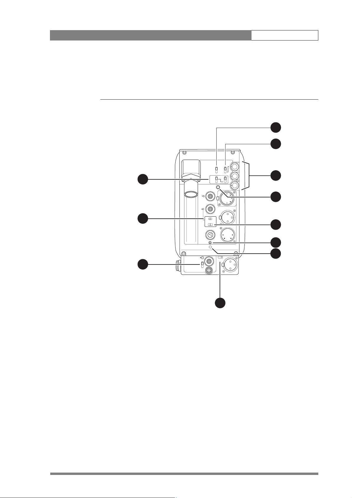
3 HD Fibre adapter controls
Figure 1 LDK 5476 HD Fibre adapter controls
1
2
Eng
Front
Off
Prod
11
Ext
Mix
CVBS (option)
Rear
Loc
Call
Eng Progr Prod
3
4
10
9
12V 1.5A DC Out
1. Intercom routing switch
2. Headset production vol. control
selection
3. Headset volume controls
Ext 1
Ext 2
TP
Script
Light
Breaker
Power on
Mic
Ext
VF
Front Rear 48V
DC in
5
6
7
48VOn
Mic 2
8
7. Power on indicator
8. Microphone 2 phantom power
switch
9. External signal selection
4. Call button
5. Audio microphone switch
6. Circuit breaker button (BREAKER)
10. Viewfinder display signal
11. Video output selection switch
Page 6

HD Fibre adapter LDK 5476 | HD Fibre adapter controls 6
3.1 Powering the camera
The power supply for the camera and adapter is normally supplied via the fibre cable
from the Base Station. The power on indicator (6) lights when power is supplied and
the camera power switch is On.
When power is supplied via the fibre cable, an output power socket supplies +12 Vdc,
1.5A maximum for powering accessories.
If excessive current flows in the camera or adapter, the circuit breaker (7) trips and
shuts off power to all the units. If this happens check the units for faults and if
necessary take corrective action before pressing the circuit breaker button to reset the
power.
It is also possible to operate the camera without a fibre cable by supplying a +12 Vdc
supply to the DC input socket.
3.2 Selecting monitoring signals
Viewfinder display signal
The viewfinder can display local or external video signals. Two switches (11) determine
the signal that is displayed in the viewfinder.
Set the first switch to LOC to display the local camera Y signal in the viewfinder. (The
Ret. button on the lens also selects this signal in parallel with this switch.) If set to the
other position, then the second switch determines the signal displayed in the
viewfinder.
The second switch selects the signal displayed in the viewfinder when the viewfinder
signal selection switch is not in the LOC position. The signal then displayed is:
• EXT Base Station external input 1 or 2.
• MIX Base Station external input 1 or 2 and camera Y signal mixed.
External signal selection
The External signal selection switch (9) selects either the EXT1 or EXT 2 signal from
the Base Station.
In addition to this switch, other switches on the camera (VTR start) can be set up in the
Install menu to switch this function.
Output monitoring signal
The monitoring output selection switch (10) determines whether the viewfinder signal
from the camera or the external video signal from the Base Station is available at the
output connector
3.3 Using audio
Two high quality audio channels are available in the fibre mode. Set the gain levels (-22
to -64 dB) for these channels in the Audio section of the Install menu. A high-pass filter
for each channel can also be switched on via this menu.
.
Page 7

HD Fibre adapter LDK 5476 | HD Fibre adapter controls 7
Audio channel 1
The microphone for channel 1 is connected either to the socket at the front-right of
the camera or to the Mic 1 socket on the adapter. A 3-position switch (5) activates the
socket at the front-right or the connector at the rear. The third position selects the rear
socket with a phantom power supply (48V).
Audio channel 2
The microphone for the second audio channel is connected to the Mic 2 socket on the
adapter. A 2-position switch (8) selects a phantom power supply (48V) for the second
audio microphone.
3.4 Intercom
Three intercom channels – production (Prod), program sound (Prog) and engineering
(Eng) – are sent from the Base Station to the camera operator's headset. The camera
operator's intercom microphone signal is sent to the Base Station. A tracker can also
connect a headset to the intercom system to receive all of the channels from the Base
Station and the camera operator's microphone signal as well. The tracker's
microphone signal is passed to the camera operator and to the Base Station.
The Intercom section of the Install menu contains various settings for all these
channels. Signals for left and right headset muffs and sidetone levels can be selected.
Intercom microphone amplification levels, phantom power supply and microphone on/
off switches are also available in this menu.
Additional controls are found on the back of the adapter.
Intercom microphone routing switch
This 3-position switch (1) routes the camera operator's intercom microphone signal to
engineering (Eng) or production (Prod), or turns off the intercom. Use the VTR Start
button at the front of the camera, or the VTR button on the lens, to send the camera
operator's intercom microphone signal to production, regardless of the position of this
switch.
Production volume control selection
Use this 2-position switch (2) to control the volume of the production signal in the
intercom either at the front of the camera
or at the rear of the adapter.
Intercom headset volume controls
• Prod - adjusts the volume of the production signal to the camera operator's headset
when selection switch (2) is in the REAR position.
• Prog - adjusts the volume of the programme signal to the camera operator's
headset.
• Eng - adjusts the volume of the engineering intercom signal to the camera
operator's headset.
Page 8

HD Fibre adapter LDK 5476 | HD Fibre adapter controls 8
3.5 Communication
Call button
Press this momentary button (4) to send a signal to the control panels calling for
attention. The ND/RE indicator in the 1.5-inch viewfinder shows when a call signal is
sent or received.
Data channel
The Aux connector on the side of the adapter provides analogue control signals and
facilities for the connection of a two-way private data channel between camera and
Base Station. In the Install menu, the tracker microphone and engineering intercom
channels can be selected to carry the private data instead of their normal function.
On-air signal
The tracker connector on the side of the adapter, as well as providing full intercom
facilities for the dolly or crane driver, also carries a tally signal and a +12 Vdc power
supply. This allows an external on-air lamp to be used.
Page 9

HD Fibre adapter LDK 5476 | HD Fibre adapter connectors 9
4 HD Fibre adapter connectors
Figure 2 LDK 5476 HD Fibre adapter connector location
Fibre connector
Front
Eng
Off
Prod
Rear
Loc
Ext
Mix
Eng Progr Prod
Intercom headset
CVBS output
CVBS (option)
Call
Viewfinder/Ext. video output
Script light power supply
Teleprompter output
DC power and tally output
REF
IN
Ext 1
Ext 2
12V 1.5A DC Out
Script
Light
Breaker
Power on
TP
VF
Front Rear 48V
Mic
Ext
Audio microphone 1
input
DC power supply
DC in
48VOn
input
Audio microphone 2
Mic 2
input
Tracker
Aux
Reference signal input
Auxiliary
connector
Tracker
communication
connector
Page 10

HD Fibre adapter LDK 5476 | HD Fibre adapter connectors 10
4.1 Fibre connector
Figure 3 Fibre connector
Optic fibre channel A
Power supply
Lemo hybrid optical connector (SMPTE 304M): panel view (X100)
4.2 CVBS output connector
Figure 4 CVBS output connector
Power supply return
Optic fibre channel B
This socket provides a 1.0 Vpp CVBS output video signal.
BNC connector: panel view (X105)
4.3 Viewfinder / External video output connector
Figure 5 Viewfinder / External video output connector
This socket provides a 1.0 Vpp VBS output viewfinder
signal or the external video signal from the Base Station.
NC connector: panel view (X106)
Page 11

HD Fibre adapter LDK 5476 | HD Fibre adapter connectors 11
4.4 Script light power supply socket
Figure 6 Script light power supply output connector
1. +12 Vdc (maximum dissipation 3W)
2. Power return
3. Shield
1
2
3
Fischer 3-pole female: panel view (X102)
4.5 Teleprompter video output connector
Figure 7 Teleprompter video output connector
BNC connector: panel view (X112)
4.6 DC power and tally output socket
Figure 8 DC power and tally output connector
1
4
2
3
This socket supplies the 1Vpp teleprompter signal applied
to the Base Station.
1. Ground
2. On air
3. No connection
4. +12 Vdc (max. 18W)
Shield of cable directly to the connector housing.
The socket provides access to an internal tally switch.
When the camera is on-air, the contact of the internal
relay is closed.
Hirose 4-pole female: panel view (X110)
Page 12

HD Fibre adapter LDK 5476 | HD Fibre adapter connectors 12
4.7 Audio microphone 2 connector
Figure 9 Audio microphone 2 connector
1. Audio Screen
2. Audio In
1
3
3. Audio Return
Microphone impedance >200 ohm
Sensitivity range: -64 to -24 dBu
XLR 3-pole female; panel view (X107)
4.8 DC power input socket
Caution
The input voltage must not exceed +17 Vdc.
Figure 10 DC power input connector
1
23
2
4
Signal at pin 2 of audio input is in phase with signal at pin
2 of audio output.
1. Ground
2. No connection
3. No connection
4. +10.5 Vdc . . . +17 Vdc
This socket accepts a DC voltage of 12V nominal.
Maximum power consumption 23W.
XLR 4-pin male: panel view (X101)
Page 13

HD Fibre adapter LDK 5476 | HD Fibre adapter connectors 13
4.9 Audio microphone 1 connector
Figure 11 Audio microphone 1 connector
1. Audio Screen
2. Audio In
1
3
3. Audio Return
Microphone impedance >200 ohm
Sensitivity range: -64 to -24 dBu
2
XLR 3-pole female; panel view (X107)
4.10 Intercom headset connector
Figure 12 XLR intercom headset connector
1
2
3
4
5
XLR 5-pole female; panel view (X104)
Signal at pin 2 of audio input is in phase with signal at pin
2 of audio output.
1. Microphone return
2. Microphone
3. Telephone return
4. Telephone left
5. Telephone right
Microphone level: -64 dBu / -24 dBu switchable
Microphone impedance: >600 Ohm
Telephone level: +6 dBu nominal
Telephone output impedance: <50 Ohm
Figure 13 Tuchel intercom headset connector
1. Telephone left
2. Not connected
1
2
3
6
5
4
Tuchel 6-pole female; panel view (X104)
3. Microphone
4. Microphone return
5. Telephone right
6. Telephone return
Microphone level: -64 dBu / -24 dBu switchable
Microphone impedance: >600 Ohm
Telephone level: +6 dBu nominal
Telephone output impedance: <50 Ohm
Page 14

HD Fibre adapter LDK 5476 | HD Fibre adapter connectors 14
4.11 Reference input connector
Figure 14 Reference input connector
This conector is used to supply a 0.6 Vpp HD tri-level
reference signal to the camera for genlocking.
BNC connector: panel view (X111)
4.12 Tracker communications connector
Figure 15 Tracker communications connector
1. On-air signal return
2. Tracker microphone return
10
9
11
23
8
1
4
5
7
6
ischer 11-pole female; panel view
anel part number (X108): 3922 040 02463
3. Tracker microphone input
4. Production tracker
5. Sidetone/engineering tracker
6. Intercom return
7. Program sound tracker
8. Cameraman microphone
9. Tally control tracker (Cmos level, R out = 1k)
10. +12V; I max. = 100mA
11. +12V return
Microphone level: -58dBu/-20dBu switchable
Microphone impedance: 200 ohm
Telephone level: + 6dBu
Telephone output impedance: <10 ohm
Page 15

HD Fibre adapter LDK 5476 | HD Fibre adapter connectors 15
4.13 Auxiliary connector
Figure 16 Auxiliary connector
1. +5VL
2. 0VL
10
9
11
23
8
1
4
5
7
6
3. AN0
4. AN1
5. Spare
6. On-air n.c.
7. Private Data Camera - Base Station
8. Ground
9. Private Data Base Station - Camera
10. Ground
11. Shield
Private data input signals: 0 <0.8 Volt; 1 >2.4 Volt
max. level: +/-12 Volt
input impedance: >100 kOhm
baud rate: 2400 bits/s nom; 4800 bits/s max.
Fischer 11-pole female; panel view
Panel part number (X109): 3922 040 02512
Private data output signals: C-MOS levels 5V
output impedance: <1 kOhm.
Analogue outputs (AN0 and AN1) output level: 0 - 5 Volt
output impedance: 100 Ohm
Page 16

HD Fibre adapter LDK 5476 | Install menu 16
5 Install menu
Table 2 Install menu (HD Fibre camera)
Main menu items Purpose
Video Mode Select the acquisition mode
HD aspect ratio 16:9, Wide
Disable Camera on/off
IR receiver on/off
OnAir Lamp on/off
Intercom set intercom values
Audio set gain and filter
Timing set subcarrier and h-phase
Notch on/off
Chroma on/off
Aspect ratio select aspect ratio values
Exposure set lighting and clear scan values
Gain preset set gain preset values
Autowhite set autowhite speed and gain
Quick Smart Touch on/off
Private Data select data for intercom channels
Heater on/off switch for SuperXpander heater
Buttons assign functions to buttons
 Loading...