

Page 1
LDK 5309/10
User’s Guide
3922 496 31721 August 2011 v1.0
9-inch LCD HD color viewfinder
Page 2

Declaration of Conformity
We, Grass Valley Nederland B.V., Kapittelweg 10, 4827 HG Breda, The Netherlands,
declare under our sole responsibility that this product is in compliance with the
following standards:
- EN60065 : Safety
- EN55103-1: EMC (Emission)
- EN55103-2: EMC (Immunity)
following the provisions of:
a. the Low Voltage directive 2006/95/EC
b. the EMC directive 2004/108/EC
FCC Class A Statement
This product generates, uses, and can radiate radio frequency energy and if not
installed and used in accordance with the instructions, may cause interference to
radio communications.
It has been tested and found to comply with the limits for a class A digital device
pursuant to part 15 of the FCC rules, which are designed to provide reasonable
protection against such interference when operated in a commercial environment.
Operation of this product in a residential area is likely to cause interference in which
case the user at his own expense will be required to take whatever measures may
be required to correct the interference.
Copyright
Copyright Grass Valley Nederland B.V. 2011. Copying of this document and giving it
to others, and the use or communication of the contents thereof, are forbidden
without express authority. Offenders are liable to the payment of damages. All rights
are reserved in the event of the grant of a patent or the registration of a utility model
or design. Liable to technical alterations in the course of further development.
Trademarks
Grass Valley is a trademark of Grass Valley, Inc. All other tradenames referenced are
service marks, trademarks, or registered trademarks of their respective companies.
Website
Visit the Grass Valley public website to download the latest user’s guide updates and
additional information about your broadcast product: www.grassvalley.com
Page 3

Table of contents
Chapter 1 – Introduction
1.1 Overview . . . . . . . . . . . . . . . . . . . . . . . . . . . . . . . . . . . . . . . . 13
1.2 Locations of indicators and controls . . . . . . . . . . . . . . . . . . 14
1.2.1 Front panel view . . . . . . . . . . . . . . . . . . . . . . . . . . . . . 14
1.2.2 Back panel view . . . . . . . . . . . . . . . . . . . . . . . . . . . . . 15
Chapter 2 – Installation
2.1 Attaching the quick mount support . . . . . . . . . . . . . . . . . . . 17
2.2 Mounting the viewfinder . . . . . . . . . . . . . . . . . . . . . . . . . . . 18
2.3 Attaching accessories . . . . . . . . . . . . . . . . . . . . . . . . . . . . . . 19
2.3.1 Sunhood . . . . . . . . . . . . . . . . . . . . . . . . . . . . . . . . . . . 19
2.3.2 LDK 6400/20 Identification numbers (option) . . . . . . . 20
2.4 Adjusting the position. . . . . . . . . . . . . . . . . . . . . . . . . . . . . . 20
2.4.1 Height adjustment. . . . . . . . . . . . . . . . . . . . . . . . . . . . 20
2.4.2 Tilting. . . . . . . . . . . . . . . . . . . . . . . . . . . . . . . . . . . . . . 21
2.4.3 Panning . . . . . . . . . . . . . . . . . . . . . . . . . . . . . . . . . . . . 22
Chapter 3 – Operation
3.1 Controls . . . . . . . . . . . . . . . . . . . . . . . . . . . . . . . . . . . . . . . . . 25
3.1.1 Power switch. . . . . . . . . . . . . . . . . . . . . . . . . . . . . . . . 25
3.1.2 Buttons . . . . . . . . . . . . . . . . . . . . . . . . . . . . . . . . . . . . 25
3.1.3 Rotary controls . . . . . . . . . . . . . . . . . . . . . . . . . . . . . . 26
3.1.4 Indicators. . . . . . . . . . . . . . . . . . . . . . . . . . . . . . . . . . . 27
LDK 5309/10 9-inch LCD HD color viewfinder User’s Guide (v1.0) 3
Page 4

3.2 Operational functions . . . . . . . . . . . . . . . . . . . . . . . . . . . . . . 28
3.2.1 Box. . . . . . . . . . . . . . . . . . . . . . . . . . . . . . . . . . . . . . . . 28
3.2.2 Monochrome . . . . . . . . . . . . . . . . . . . . . . . . . . . . . . . . 28
3.2.3 Ext1 . . . . . . . . . . . . . . . . . . . . . . . . . . . . . . . . . . . . . . . 28
3.2.4 Ext2 . . . . . . . . . . . . . . . . . . . . . . . . . . . . . . . . . . . . . . . 28
3.2.5 Zoom . . . . . . . . . . . . . . . . . . . . . . . . . . . . . . . . . . . . . . 29
3.2.6 Focus bar . . . . . . . . . . . . . . . . . . . . . . . . . . . . . . . . . . . 29
3.2.7 Text . . . . . . . . . . . . . . . . . . . . . . . . . . . . . . . . . . . . . . . 29
3.2.8 Call . . . . . . . . . . . . . . . . . . . . . . . . . . . . . . . . . . . . . . . .29
3.3 Menus . . . . . . . . . . . . . . . . . . . . . . . . . . . . . . . . . . . . . . . . . . . 30
3.3.1 Camera system menu . . . . . . . . . . . . . . . . . . . . . . . . . 30
3.3.2 Viewfinder setup menu . . . . . . . . . . . . . . . . . . . . . . . . 31
3.3.3 Button assignment menu . . . . . . . . . . . . . . . . . . . . . . 31
3.4 Cleaning the viewfinder. . . . . . . . . . . . . . . . . . . . . . . . . . . . . 32
Chapter 4 – Viewfinder setup menu
4.1 Menu contents . . . . . . . . . . . . . . . . . . . . . . . . . . . . . . . . . . . . 33
4.1.1 Diagnostics (“Diag”) . . . . . . . . . . . . . . . . . . . . . . . . . .33
4.1.2 Configuration #1 (“Config1”) . . . . . . . . . . . . . . . . . . . . 34
4.1.3 Configuration #2 (“Config2”) . . . . . . . . . . . . . . . . . . . . 34
4.1.4 Indicator adjustment . . . . . . . . . . . . . . . . . . . . . . . . . .35
4.1.5 Focus (“Focus”). . . . . . . . . . . . . . . . . . . . . . . . . . . . . . 35
4.1.6 Zoom (“Zoom”) . . . . . . . . . . . . . . . . . . . . . . . . . . . . . . 36
4.1.7 Color (“Color”) . . . . . . . . . . . . . . . . . . . . . . . . . . . . . . .36
4.1.8 Monochrome (“Mono”) . . . . . . . . . . . . . . . . . . . . . . . . 37
4.1.9 Box setup (“Box”) . . . . . . . . . . . . . . . . . . . . . . . . . . . . 37
4.2 Viewfinder status information . . . . . . . . . . . . . . . . . . . . . . . 38
Chapter 5 – Specifications
5.1 Technical specifications. . . . . . . . . . . . . . . . . . . . . . . . . . . . . 39
5.1.1 General. . . . . . . . . . . . . . . . . . . . . . . . . . . . . . . . . . . . . 39
5.1.2 Screen . . . . . . . . . . . . . . . . . . . . . . . . . . . . . . . . . . . . . 39
5.1.3 Dimensions . . . . . . . . . . . . . . . . . . . . . . . . . . . . . . . . . 40
5.1.4 Accessories . . . . . . . . . . . . . . . . . . . . . . . . . . . . . . . . . 40
5.2 Connectors . . . . . . . . . . . . . . . . . . . . . . . . . . . . . . . . . . . . . . . 41
5.2.1 Viewfinder connector (lead) . . . . . . . . . . . . . . . . . . . . .41
4 LDK 5309/10 9-inch LCD HD color viewfinder User’s Guide (v1.0)
Page 5

LDK 5309/10 9-inch LCD HD color viewfinder User’s Guide (v1.0) 5
Page 6

End-of-life product recycling
Grass Valley’s innovation and excellence in product design also extends to the
programs we’ve established to manage the recycling of our products. Grass Valley
has developed a comprehensive end-of-life product take back program for recycle or
disposal of end-of-life products. Our program meets the requirements of the
European Union’s WEEE Directive and in the United States from the Environmental
Protection Agency, individual state or local agencies.
Grass Valley’s end-of-life product take back program assures proper disposal by use
of Best Available Technology. This program accepts any Grass Valley branded
equipment. Upon request, a Certificate of Recycling or a Certificate of Destruction,
depending on the ultimate disposition of the product, can be sent to the requester.
Grass Valley will be responsible for all costs associated with recycling and disposal,
including freight, however you are responsible for the removal of the equipment
from your facility and packing the equipment ready for pickup.
For further information on the Grass Valley product take back system please contact
Grass Valley at + 800 80 80 20 20 or +33 1 48 25 20 20 from most other countries.
In the US and Canada please call 800-547-8949 or 530-478-4148. Ask to be
connected to the EH&S Department. In addition, information concerning Grass
Valley’s environmental policy can be found at:
www.grassvalley.com/about/environmental-policy
Notes
• The viewfinder's LCD panel is manufactured using high precision technology
that yields a quality of 99.99% or higher. However, it is possible that one or
more pixels may constantly display a single color or be permanently off. This
does not indicate a defective display and the camera's video signals are not
affected.
• Using the viewfinder at low temperatures may result in a decrease of dynamic
resolution and brightness.
6 LDK 5309/10 9-inch LCD HD color viewfinder User’s Guide (v1.0)
Page 7

Packing/Unpacking
Inspect the shipping container for evidence of damage immediately after receipt. If
the shipping container or cushioning material is damaged, it should be kept until the
contents of the shipment have been checked for completeness and the unit has
been checked mechanically and electrically.
The shipping container should be placed upright and opened from the top. Remove
the cushioning material and lift out the contents.
The contents of the shipment should be checked against the packing list. If the
contents are incomplete, if there is mechanical damage or defect, or if the unit does
not perform correctly when unpacked, notify your Grass Valley sales or service
centre within eight days.
If the shipping container shows signs of damage or stress, notify the carrier as well.
If the unit is being returned to Grass Valley for servicing, try to use the containers
and materials of the original packaging. Attach a tag indicating the type of service
required, return address, model number, full serial number and the return number
which will be supplied by your Grass Valley service centre.
If the original packing can no longer be used, the following general instructions
should be used for repacking with commercially available materials:
• Wrap unit in heavy paper or plastic.
• Use a strong shipping container.
• Use a layer of shock-absorbing material around all sides of the unit to provide
firm cushioning and prevent movement inside container.
• Seal shipping container securely.
• Mark shipping container FRAGILE to ensure careful handling.
LDK 5309/10 9-inch LCD HD color viewfinder User’s Guide (v1.0) 7
Page 8

Important information
Read this information carefully before installing this equipment and retain them for
future reference. Read and comply with the warning and caution notices that appear
in the manual. Any changes or modifications not expressly approved in this manual
could void your authority to operate this equipment.
Safety Summary
This information is intended as a guide for trained and qualified personnel who are
aware of the dangers involved in handling potentially hazardous electrical/electronic
equipment. It is not intended to contain a complete list of all safety precautions
which should be observed by personnel in using this or other electronic equipment.
The installation of this equipment involves risks both to personnel and equipment
and must be performed only by qualified personnel exercising due care.
During installation and operation of this equipment, local building safety and fire
protection standards must be observed.
Whenever it is likely that safe operation is impaired, the apparatus must be made
inoperative and secured against any unintended operation. The appropriate servicing
authority must then be informed. For example, safety is likely to be impaired if the
apparatus fails to perform the intended function or shows visible damage.
The unit is protected according to IEC 60529 IPX54 (dust-protected and resistant to
splashing water).
Warnings
Warnings indicate danger that requires correct procedures or practices to prevent
death or injury to personnel.
• Do not modify this equipment;
• Do not use any accessories other than those recommended by the
manufacturer;
• In case of an emergency ensure that the power is disconnected;
• Mount equipment so that power lead can be accessed to disconnect power;
• There are no user serviceable parts inside. Refer servicing to qualified
personnel only or contact your local Grass Valley representative;
• Observe local building safety, fire protection and electrical installation
standards during installation and operation of this equipment;
• Whenever it is likely that safe operation is impaired, the apparatus must be
made inoperative and secured against any unintended operation.
8 LDK 5309/10 9-inch LCD HD color viewfinder User’s Guide (v1.0)
Page 9

Cautions
Cautions indicate procedures or practices that should be followed to prevent
damage or destruction to equipment or property.
• Do not subject the unit to severe shocks or vibration;
• Do not expose the unit to extremes of temperature;
• To prevent risk of overheating, ventilate the product correctly;
LDK 5309/10 9-inch LCD HD color viewfinder User’s Guide (v1.0) 9
Page 10

Wichtige Hinweise
Lesen Sie bitte diese Hinweise genau bevor Sie diese Apparatur installieren und
erhalten Sie Sie für künftiges Nachslagen. Beachten und Lesen Sie alle mit
“Achtung” und “Vorsicht” gekennzeichneten Warnhinweise.
Änderungen haben zur Folge, dass die Garantie ungültig wird und der Benutzer für
etwaige durch die veränderte Ausrüstung verursachte Störungen haftbar gemacht
werden könnte.
Sicherheit (Zusammenfassung)
Diese Informationen sind als Leitfaden für qualifiziertes Fachpersonal gedacht, das
die Gefahren beim Umgang mit potenziell gefährlicher elektrischer/elektronischer
Ausrüstung kennt. Es handelt sich dabei nicht um eine vollständige
Zusammenstellung aller Sicherheitsvorkehrungen, die beim Gebrauch dieser oder
anderer elektronischer Geräte zu beachten sind.
Die Montage, Wartung und Instandsetzung dieser Ausrüstung ist mit Risiken für
Personal und Ausrüstung verbunden und darf nur von qualifiziertem Personal
vorgenommen werden, wobei mit der nötigen Sorgfalt vorzugehen ist.
Beim Einbau und Betrieb dieser Ausrüstung müssen die örtlichen
Gebäudesicherheits- und Brandschutzvorschriften beachtet werden.
Wenn eine Beeinträchtigung des sicheren Betriebs wahrscheinlich ist, muss das
Gerät außer Betrieb gesetzt und gegen ungewollten Betrieb gesichert werden. Dann
muss der zuständige Kundendienst benachrichtigt werden. Eine Beeinträchtigung
der Sicherheit ist zum Beispiel dann wahrscheinlich, wenn das Gerät nicht wie
vorgesehen funktioniert oder einen sichtbaren Schaden aufweist.
Dieser Ausrüstung ist gemäß IE 60529 IPX54 geschützt (Staub- und
Spritwassergeschützt).
Vorsicht
Mit “Vorsicht” wird auf eine Gefahr hingewiesen, die korrekte Arbeits- oder
Verfahrensweisen erfordert, um Tod oder Verletzung zu verhindern.
• An dieser Ausrüstung dürfen keine Änderungen vorgenommen werden;
• Es sollen nur von den Hersteller empfohlene Zubehöre verwendet werden;
• Bei Eintreten eines Notfalls unbedingt die Stromzufuhr abschalten;
• Ausrüstung so montieren, daß das kabel zum Abschalten der Stromzufuhr
zugänglich ist;
10 LDK 5309/10 9-inch LCD HD color viewfinder User’s Guide (v1.0)
Page 11

Achtung
• Dieses Produkt enthält keine Anwenderteile. Reparatur und Wartung nur von
qualifiziertem Fachpersonal vornehmen lassen oder nehmen Sie Kontakt auf
mit Ihrem Grass Valley Vertretene;
• Beim Einbau und Betrieb dieser Ausrüstung müssen die örtlichen
Gebäudesicherheits- und Brandschutzvorschriften beachtet werden;
• Wenn eine Beeinträchtigung des sicheren Betriebs wahrscheinlich ist, muss
das Gerät außer Betrieb gesetzt und gegen ungewollten Betrieb gesichert
werden.
Mit “Achtung” werden Arbeitsanweisungen gekennzeichnet, die zu befolgen sind,
um eine Beschädigung oder Zerstörung der Ausrüstung bzw. von Eigentum zu
verhindern.
• Dieses Produkt darf nicht an extremen stöße oder Zittern ausgesetzt werden;
• Dieses Produkt darf nicht an extremen Temperaturen ausgesetzt werden;
• Um einer Überhitzungsgefahr vorzubeugen, ist das Produkt korrekt zu
belüften.
LDK 5309/10 9-inch LCD HD color viewfinder User’s Guide (v1.0) 11
Page 12

12 LDK 5309/10 9-inch LCD HD color viewfinder User’s Guide (v1.0)
Page 13

Chapter 1
Introduction
1.1 Overview
The LDK 5309/10 is a high quality, flat panel color viewfinder. Its light-weight
construction, multi-format compatibility and its high brightness performance make
this viewfinder a perfect match for EFP/portable, studio and outside broadcast
applications. The supplied sun hood provides excellent shading fit for outdoor
situations.Its 9-inch diagonal screen size makes fast and accurate focussing easy.
The LDK 5309/10 viewfinder is designed to work with Grass Valley’s LDK 8000
(Elite), LDK 4000 (Elite) and LDK 3000 series HD cameras and accommodates all
required HD frame rates and video modes.
Compact design
The compact design allows for great operator flexibility with much wider panning
and tilting angles compared to CRT based viewfinders.
Chapter 1 - Introduction
Camera operation
Due to its advanced user interface and built-in text generator, the viewfinder allows
for easy access to the camera system menu.
Focus bar
Aids focussing by providing a visual indication of the sharpness of the image.
Viewfinder zoom
The viewfinder picture can be zoomed in for precise focussing while the full picture
overview is shown in a small overlay area.
Color adjustment
Without influencing the main video signal the viewfinder color temperature can be
adjusted to suit the operator’s personal preference.
Assignable buttons
Three user buttons are provided that can be assigned to a range of operational
functions, customizing the LDK 5309/10 to your personal preferences.
LDK 5309/10 9-inch LCD HD color viewfinder User’s Guide (v1.0) 13
Page 14
Chapter 1 - Introduction
1
2
3
4
2’
3’
4’
6
7
8
9
10
11
5
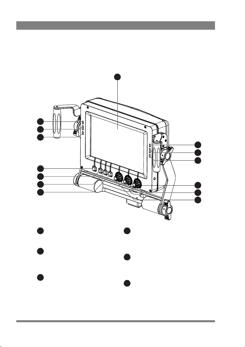
Display area
Active viewfinder display area.
ISO indicators
These yellow indicators light when the
camera is in ISO status.
On-Air indicators
These red indicators light when the
camera is On-Air.
1
2
3
Call indicators
These green Call indicators light when a
Call signal is activated.
Contrast control
Controls the contrast level of the VF
display.
Brightness control
Controls the brightness level of the VF
display.
4
5
6
1.2 Locations of indicators and controls
1.2 .1 Front panel view
14 LDK 5309/10 9-inch LCD HD color viewfinder User’s Guide (v1.0)
Page 15
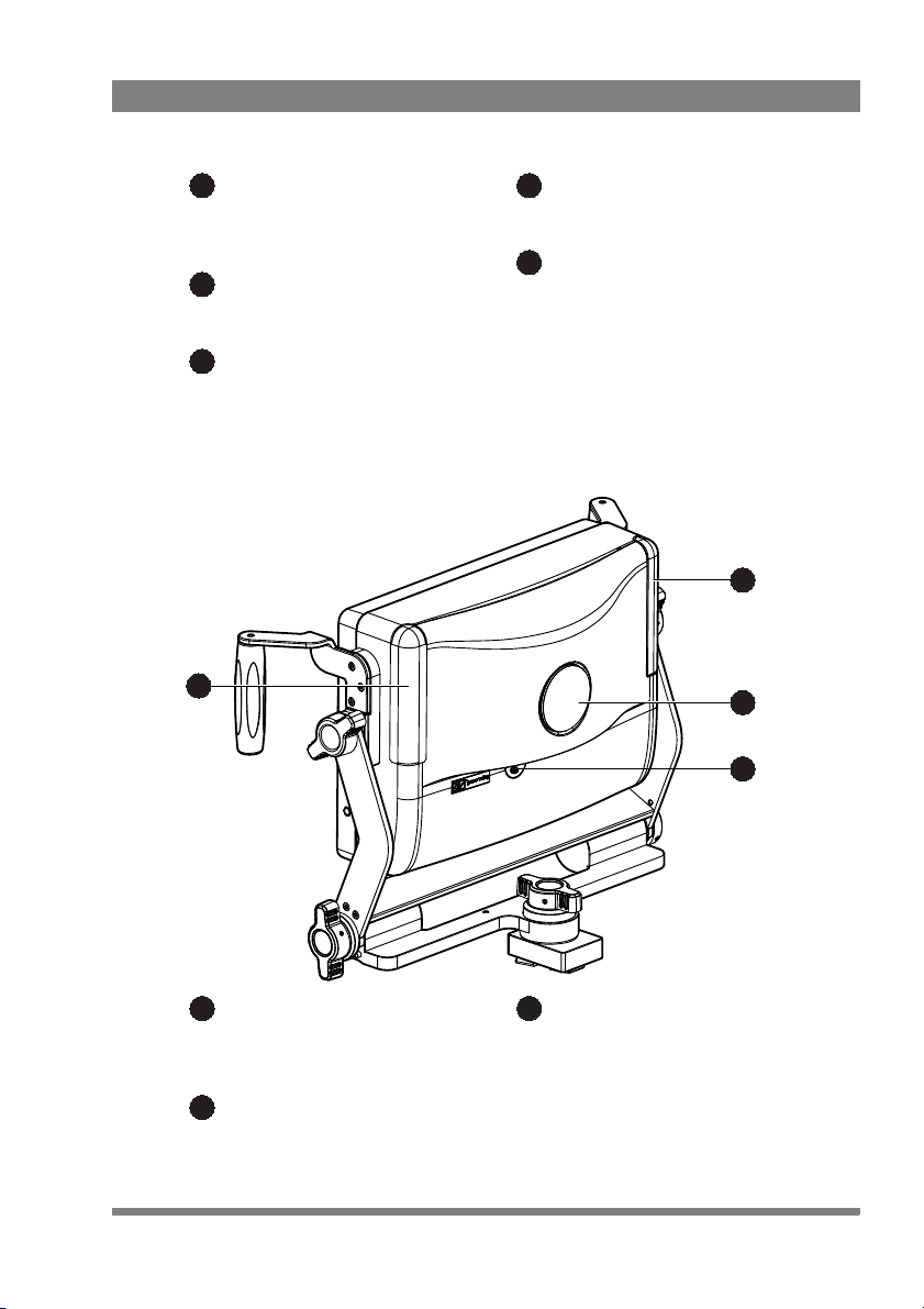
1.2 .2 Back panel view
Peaking control
Controls the level of peaking that is
applied to the viewfinder signal.
User button 3
Assignable user button 3.
User button 2
Assignable user button 2.
7
8
9
User button 1
Assignable user button 1.
Menu button
Press this button to open the viewfinder,
camera system or button assignment
menus.
10
11
12
14
13
12’
Tally lights (On-Air)
These two bright red tally lights are lit
when the camera is On-Air.
Number plate
Recess for camera number plate
(optional).
12
13
Power switch
This switch is used to switch the
viewfinder on or off.
14
Chapter 1 - Introduction
LDK 5309/10 9-inch LCD HD color viewfinder User’s Guide (v1.0) 15
Page 16

Chapter 1 - Introduction
16 LDK 5309/10 9-inch LCD HD color viewfinder User’s Guide (v1.0)
Page 17

Chapter 2 - Installation
Note
(2) Attach
quick mount
support
(1) Remove
quick mount
block
Chapter 2
Installation
2.1 Attaching the quick mount support
For improved viewfinder stability it is recommended to exchange the existing quick
mount block with the supplied quick mount support.
To attach the quick mount support to the camera adapter proceed as follows:
1. Loosen the four (Torx 15) screws from the existing quick mount block and
remove the block from the camera adapter.
2. Fit the quick mount support into the hole and fasten the support using the four
existing screws and two supplied (Torx 20) screws at the sides.
LDK 5309/10 9-inch LCD HD color viewfinder User’s Guide (v1.0) 17
Page 18

2.2 Mounting the viewfinder
Note
release
lever
V-block
quick mount
block
To mount the viewfinder on top of the camera adapter proceed as follows:
1. Switch off the camera.
2. Slide the V-block of the viewfinder onto the quick mount block on the camera
adapter until it clicks firmly into place.
Chapter 2 - Installation
3. Connect the viewfinder cable to the viewfinder connector on the camera head
4. Guide the cable along the top of the camera body.
When the LDK 5309/10 is used with a camera that is mounted in a SuperXpander,
make sure to plug the viewfinder cable into the SuperXpander VF socket, not the
camera VF socket.
To release the viewfinder proceed as follows:
1. Switch off the camera.
2. Disconnect the viewfinder cable from the camera head or SuperXpander
viewfinder socket.
3. Press the release lever and slide the viewfinder out of the quick mount block.
18 LDK 5309/10 9-inch LCD HD color viewfinder User’s Guide (v1.0)
Page 19

2.3 Attaching accessories
Tip
2.3.1 Sunhood
A short sunhood is supplied for outdoor use. To attach the sunhood to the viewfinder
proceed as follows:
Chapter 2 - Installation
1. Make sure that the viewfinder is mounted and that its position is fixed.
2. Lift the sunhood above the viewfinder and lower it until the hooked edges at
the sides touch the guiding rail on the viewfinder.
3. Slide down the sunhood until it clicks into place.
Draw out and tilt the upper half of the sunhood to get a larger vertical viewing angle.
LDK 5309/10 9-inch LCD HD color viewfinder User’s Guide (v1.0) 19
Page 20

Chapter 2 - Installation
Caution
Note
Do not hold the sunhood to carry the viewfinder as it may cause damage.
2.3.2 LDK 6400/20 Identification numbers (option)
A set of camera identification numbers (1 to 15) is available as an option. To mount a
number remove the blind number plate from the back panel of the viewfinder and
click the number of choice into the holes in the recess.
2.4 Adjusting the position
Adjustment range may be limited when other accessories are attached to the
camera.
2.4.1 Height adjustment
The height of the viewfinder can be adjusted over a wide range.
1. Loosen the two upper rotation knobs with two hands in a contrary direction;
2. Loosen lower rotation knob (at the right).
.
20 LDK 5309/10 9-inch LCD HD color viewfinder User’s Guide (v1.0)
Page 21
3. Bring the viewfinder to the desired height using the hand grips and fasten the
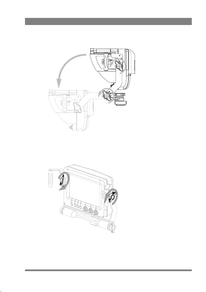
2.4.2 Tilting
The viewfinder can be tilted up and down.
1. Loosen both rotation knobs with two hands in a contrary direction.
Chapter 2 - Installation
lower rotation knob and then the two upper knobs.
LDK 5309/10 9-inch LCD HD color viewfinder User’s Guide (v1.0) 21
Page 22

2. Tilt the viewfinder to the desired angle and fasten the rotation knobs.
2.4.3 Panning
The viewfinder can be panned over an angle of 90° to the right and 90° to the left.
1. Reach behind the viewfinder and loosen the rotation locking wheel.
Chapter 2 - Installation
22 LDK 5309/10 9-inch LCD HD color viewfinder User’s Guide (v1.0)
Page 23

Chapter 2 - Installation
2. Grasp the side bars and rotate the viewfinder to the desired angle and fasten
the rotation locking wheel.
LDK 5309/10 9-inch LCD HD color viewfinder User’s Guide (v1.0) 23
Page 24

Chapter 2 - Installation
24 LDK 5309/10 9-inch LCD HD color viewfinder User’s Guide (v1.0)
Page 25

Chapter 3
MENU BOX
MONO ZOOM Pk:20 Br:50 Cn:99
menu
button
user
buttons
Operation
3.1 Controls
3.1.1 Power switch
The toggle switch at the back panel is used to switch the viewfinder on or off. When
the viewfinder is switched off, the left green LED indicator flashes. The power to the
viewfinder is supplied by the camera trough the viewfinder lead cable.
3.1.2 Buttons
The front panel of the viewfinder holds the operational controls.
Chapter 3 - Operation
Menu button
This button is used the enter the camera system menu, the viewfinder setup menu
or the button assignment menu. Refer to “Menus” on page 30 for a detailed
description of these menus.
LDK 5309/10 9-inch LCD HD color viewfinder User’s Guide (v1.0) 25
Page 26

User buttons
Tip
MENU BOX
MONO ZOOM Pk:50 Br:50 Cn:50
Peaking
control
Brightness
control
Contrast
control
Three buttons can be assigned to different operational functions. Their default
functions are: Box, Mono and Zoom. Refer to “” on page 27 for more information
about these functions and other functions that can be assigned.
3.1.3 Rotary controls
Adjust the viewfinder parameters to your personal preference using the rotary
controls:
Chapter 3 - Operation
Peaking control (A)
Controls the level of peaking that is applied to the viewfinder signal. Peaking makes
the edges of the image look sharper. Turn the rotary control clockwise to increase
peaking. The adjustment range is from 0 to 99 and its factory default value is 20.
When camera gain is set to high values, reduce peaking level for a better image.
Brightness control (B)
Controls the brightness level of the viewfinder display. Turn the rotary control
clockwise to increase brightness. The adjustment range is from 0 to 99 and its
factory default value is 50.
Contrast control (C)
Controls the contrast level of the viewfinder display. Turn the rotary control
clockwise to increase contrast. The adjustment range is from 0 to 99 and its factory
default value is 99.
26 LDK 5309/10 9-inch LCD HD color viewfinder User’s Guide (v1.0)
Page 27

3.1.4 Indicators
Tip
ISO indicators (yellow)
The yellow LEDs light to indicate that the camera is currently in ISO mode.
On Air indicators (red)
The red LEDs light to indicate that the camera is currently On Air.
Call indicators (green)
The green LEDs light to attract attention when a Call signal is activated.
The indicator brightness level can be changed in the viewfinder setup menu. Refer to
“Configuration #2 (“Config2”)” on page 34 for more information.
Tally lights (red)
The large red tally lights at the back of the viewfinder light when the camera is
currently On-Air. These lights can be enabled or disabled in the camera system
menu. Brightness level can also be adjusted using an Operational or Master Control
Panel or a SuperXpander.
Chapter 3 - Operation
LDK 5309/10 9-inch LCD HD color viewfinder User’s Guide (v1.0) 27
Page 28

3.2 Operational functions
box type line type full type
Many operational functions can be assigned to the user buttons at the bottom of the
viewfinder. Refer to “Button assignment menu” on page 31 to read more about
assigning user buttons.
3.2.1 Box
Turns the framing box on or off. This superimposed box is a very useful feature to
help focussing and framing while shooting. Three box types are available:
The framing box can be selected and set up in the viewfinder setup menu. Refer to
“Box setup (“Box”)” on page 37 for more information.
3.2.2 Monochrome
Switches the viewfinder to monochrome mode. Select the source (Y, R, G, B or -G)
in the viewfinder setup menu. When the camera color bar is switched on, the
viewfinder returns to color mode.
Chapter 3 - Operation
3.2.3 Ext1
Press the button to show the external (return) video channel 1.
3.2.4 Ext2
Press the button to show the external (return) video channel 2.
28 LDK 5309/10 9-inch LCD HD color viewfinder User’s Guide (v1.0)
Page 29

3.2.5 Zoom
Note
Zooms in to the center of the image to indicate an uncropped (‘pixel exact’) viewing
area. Both the border color and screen position of the Picture in Picture box can be
selected in the viewfinder setup menu.
The zoom factor depends on the selected camera video mode.
3.2.6 Focus bar
The focus bar is intended to be used as a tool for the camera operator to support the
judgement of sharpness by looking at the viewfinder picture with peaking.
The screen position (top, bottom, left, right) of the focus bar can be selected in the
viewfinder setup menu. The focus bar has a peak/hold indicator (green cadre) with a
typical hold time of 2 seconds, which allows the operator to indicate the maximum
focus of the current picture.
A preset gain control is available in the viewfinder setup menu to control the
selectivity of the focus bar.
3.2.7 Text
Removes all text from the viewfinder image. This includes menu and message texts
and camera indicators. Markers and cadres are not removed from the image. Press
again to restore all text.
Chapter 3 - Operation
3.2.8 Call
Press the button to activate the system Call function. The green Call indicators on
the viewfinder light.
LDK 5309/10 9-inch LCD HD color viewfinder User’s Guide (v1.0) 29
Page 30

3.3 Menus
Note
Note
MENU DOWN
UP SELECT
Menu off
Viewfinder
Lens
Video
Install
>
Exec
>>
>>
>>
>>
Root
3.3.1 Camera system menu
The camera can be conveniently controlled by the viewfinder:
• Press the menu button to open the menus.
•Press the system menu button to open the camera system menu. The camera
system menu is superimposed on the viewfinder image.
Chapter 3 - Operation
• Use the down, up and select buttons to navigate through the menu system.
• Press the menu button to leave the camera system menu.
For more information on navigating the camera system menu and for a complete
description of the menu contents, refer to the user’s guide of your camera.
More viewfinder functions such as on-screen indicators and markers can be found in
30 LDK 5309/10 9-inch LCD HD color viewfinder User’s Guide (v1.0)
the viewfinder submenu of the camera system menu.
Page 31

3.3.2 Viewfinder setup menu
Tip
Config1
Config2
Diag
Focus
Zoom
Color
Mono
Box
CONFIG2
EXIT
<Off>
Text
<Whit>
PkCol INDADJ
NEXT
PREV
Many viewfinder functions can be set in the viewfinder setup menu:
• Press the menu button to open the menus.
•Press vf setup to open the viewfinder setup menu. At the right side of the
screen a list of submenus is shown.
• Turn the rotary control at the right to loop through the submenus. An arrow
indicates the selected submenu. The actions of the user buttons change
depending on the selected submenu.
• Carry out any changes you want to do.
• Press the menu button again to store the changes and leave the viewfinder
setup menu.
Chapter 3 - Operation
Hold the menu button and at the same time press a user button to quickly configure
the function that is assigned to that button.
3.3.3 Button assignment menu
To assign a function to each of the three user buttons, proceed as follows:
• Press the menu button to open the menus.
•Press button assign to open the button assign menu.
•Press a user button to change its switching mode: toggle between momentary
(<Mom>) and alternating (<Alt>).
LDK 5309/10 9-inch LCD HD color viewfinder User’s Guide (v1.0) 31
Page 32

• Use the rotary controls to select a function for the corresponding user button.
Note
Caution
Caution
EXIT
ASSIGN
<Alt>
Btn1
<Alt>
Btn2
<Mom>
Btn3
<Box> <Mono> <Call>
Func1 Func2 Func3
• Press EXIT ASSIGN to store the changes and leave the button assign menu.
When a button is assigned to the Call function, its switching mode is automatically
set to momentary.
3.4 Cleaning the viewfinder
Chapter 3 - Operation
Always turn off the viewfinder before cleaning the screen.
Never use cleaning solvents such as glass cleaner or soap to clean the screen.
Use a slightly damp soft cloth to clean the screen and then immediately a soft dry
cloth (preferably micro fiber tissue - no paper products) to dry the screen. The use of
purified (distilled) water is strongly recommended. Wipe gently and do not apply
strong pressure as this may damage the screen.
32 LDK 5309/10 9-inch LCD HD color viewfinder User’s Guide (v1.0)
Page 33

Chapter 4 - Viewfinder setup menu
Chapter 4
Viewfinder setup menu
4.1 Menu contents
The following tables show the items and functions that can be set up in the
viewfinder setup menu.
4.1.1 Diagnostics (“Diag”)
Control Item Valu e (s) Description
Menu EXIT DIAG Exits the diagnostics menu.
Button1 STATUS INFO Go to the viewfinder status information
screen. More information can be found in the
paragraph “Viewfinder status information” on
page 38.
Button2 — — —
Button3 — — —
Rotary1 Format <list of video
formats>
Rotary2 VF Temp nn C Info: shows the current operating
Rotary3 PREV
↑ NEXT ↓ Selects a menu from the list.
Info: shows the current video format.
temperature in degrees celsius.
LDK 5309/10 9-inch LCD HD color viewfinder User’s Guide (v1.0) 33
Page 34

Chapter 4 - Viewfinder setup menu
4.1.2 Configuration #1 (“Config1”)
Control Item Valu e (s) Description
Menu EXIT CONFIG Exits the configuration 1 menu.
Button1 — — —
Button2 — — —
Button3 FACTORY RESET Resets the viewfinder’s settings to their
factory defaults. The factory defaults are
shown in the value(s) column in bold.
Rotary1 — — —
Rotary 2 NoSignal {Black, Input,
Rotary 3 PREV
↑ NEXT ↓ Selects a menu from the list.
Bars}
Selects signal when no camera signal is
present.
4.1.3 Configuration #2 (“Config2”)
Control Item Valu e (s) Description
Menu EXIT CONFIG Exits the configuration 2 menu.
Button1 Text On > Off Turns viewfinder on-screen text on or off (this
Button2 PkCol {Whit, Red, Grn,
Blue, Yell, Mgnt,
Cyan}
Button3 INDADJ — Push to enter the indicator adjustment
Rotary1 — — —
Rotary2 — — —
Rotary3 PREV
↑ NEXT ↓ Selects a menu from the list.
is a camera system function).
Selects the color of the viewfinder peaking
indication.
submenu.
34 LDK 5309/10 9-inch LCD HD color viewfinder User’s Guide (v1.0)
Page 35

Chapter 4 - Viewfinder setup menu
4.1.4 Indicator adjustment
Control Item Valu e (s) Description
Menu EXIT INDADJ Exits the indicator adjustment menu. Set
indicator levels are stored in memory.
Button1 IndLvl {Low, Med,
High}
Button2 — — —
Button3 — — —
Rotary1 ISO 0..99 (99) Adjusts the intensity of the selected indicator
Rotary2 OnAir 0..99 (99) Adjusts the intensity of the selected indicator
Rotary3 Call 0..99 (99) Adjusts the intensity of the selected indicator
Selects the indicator level for the ISO, On-Air
and Call indicators.
(Low, Med or High) level for the ISO (yellow)
indicators (both left and right).
(Low, Med or High) level for the OnAir (red)
indicators (both left and right).
(Low, Med or High) level for the Call (green)
indicators (both left and right).
4.1.5 Focus (“Focus”)
Control Item Valu e (s) Description
Menu EXIT FOCUS Exits the focus menu.
Button1 Bar {Off, Top, Right,
Bttm, Left}
Button2 Area {Centre, All,
Button3 — —
Rotary1 Gain 0..99 (50) Sets sensitivity of focus bar range
Rotary2 P/Hold 0..99 (50) Sets peak/hold time (0 = 0 video frames, 99 =
Rotary3 PREV
LDK 5309/10 9-inch LCD HD color viewfinder User’s Guide (v1.0) 35
↑ NEXT ↓ Selects a menu from the list.
Zoom}
Selects the screen position of the focus bar.
Focus measurement window:
centre = center-weighted average; All = full
screen average; Zoom = follow zoom area
255 frames)
Page 36

Chapter 4 - Viewfinder setup menu
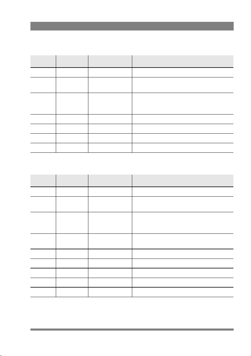
4.1.6 Zoom (“Zoom”)
Control Item Valu e (s) Description
Menu EXIT ZOOM Exits the zoom menu.
Button1 PIP On > Off Turns Picture in Picture function on or off.
Button2 PIPCol {Whit, Red, Grn,
Blue, Yell, Mgnt,
Cyan}
Button3 Pos {Centre, TopL,
TopR, BtmL,
BtmR}
Rotary1 — — —
Rotary2 — — —
Rotary3 PREV
↑ NEXT ↓ Selects a menu from the list.
Selects the color for the Picture in Picture
box.
Selects the position of the Picture in Picture
box (centre, top left, top right, bottom left,
bottom right).
4.1.7 Color (“Color”)
Control Item Valu e (s) Description
Menu EXIT COLOR Exits the color menu.
Button1 — — —
Button2 — — —
Button3 — — —
Rotary1 Satur 0..99 (50) Sets the color saturation level.
Rotary2 ColTemp 3200K .. 9500K
(6500K)
Rotary3 PREV
↑ NEXT ↓ Selects a menu from the list.
Sets the color temperature.
36 LDK 5309/10 9-inch LCD HD color viewfinder User’s Guide (v1.0)
Page 37
Chapter 4 - Viewfinder setup menu
4.1.8 Monochrome (“Mono”)
Control Item Valu e (s) Description
Menu EXIT MONO Exits the monochrome menu.
Button1 Mono On > Off Turns monochrome mode on or off (this is a
Button2 Source {Y, R, G, B, -G} Selects a signal source for the monochrome
Button3 — — —
Rotary1 — — —
Rotary2 — — —
Rotary3 PREV
↑ NEXT ↓ Selects a menu from the list.
camera system function).
image when mono mode is on (this is a
camera system function).
4.1.9 Box setup (“Box”)
Control Item Valu e (s) Description
Menu EXIT BOX Exits the box menu.
Button1 Box {Off, Box, Line,
Button2 Color {Whit, Red, Grn,
Button3 Side T/B > L/R Selects the side of the box to be adjusted:
Rotary1 Top 0..99 (24) Sets the top position of the box.
Rotary2 Bottom 0..99 (73) Sets the bottom position of the box.
Rotary1 Left 0..99 (24) Sets the left position of the box.
Rotary2 Right 0..99 (74) Sets the right position of the box.
Rotary3 PREV
↑ NEXT ↓ Selects a menu from the list.
Full}
Blue, Yell, Mgnt,
Cyan}
Selects the box type.
Selects the line color of the box.
T/B = Top/Bottom; L/R = Left/Right
LDK 5309/10 9-inch LCD HD color viewfinder User’s Guide (v1.0) 37
Page 38

Chapter 4 - Viewfinder setup menu
EXIT
Viewfinder Status Information
Type: LDKxxxx
Package: 12NC: 3922 407 xxxxx vxx.xx Date: xx/xx/xx
Firmware: 12NC: 3922 407 xxxxx vxx.xx Date: xx/xx/xx
Main Brd: 12NC: 3922 406 xxxxx St: xx Date: xx/xx/xx
PID: xxxxx
Appl.Sw: 12NC: 3922 407 xxxxx vxx.xx Date: xx/xx/xx
Conf.Sw: 12NC: 3922 407 xxxxx vxx.xx Date: xx/xx/xx
PID: xxxxxx
4.2 Viewfinder status information
The status information screen shows information about the viewfinder’s internal
hard- and software components. This information can be useful when contacting
Grass Valley service support. Press EXIT to leave this screen.
38 LDK 5309/10 9-inch LCD HD color viewfinder User’s Guide (v1.0)
Page 39

Chapter 5
Specifications
5.1 Technical specifications
5.1.1 General
Dimensions (W x H x D) 323 x 260 x 101 mm (12.7 x 10.2 x 4.0 in) without
sunhood, including mounting bracket.
Weight (approx.) 2.7 kg (5.9 lbs) without sunhood, including
mounting bracket.
Operating temperatures -20 to +45 °C (-4 to +113 °F)
Storage temperatures -25 to +70 °C (-13 to +158 °F)
Power supply -50 to -100 VDC (supplied by the camera head)
Power consumption (typ.) 20 W (supplied by the camera head)
Input signals Y, Pr, Pb
Controls Menu button, assignable user buttons (3), rotary
controls (3) for brightness, contrast and peaking.
Indicators ISO (yellow), On-Air (red), Call (green), Tally (red)
Chapter 5 - Specifications
5.1.2 Screen
Diagonal size 9 inch (~229 mm)
Colour depth 16.7M colors
Total display area 800 (H) x 480 (V) pixels
Active image area 800 (H) x 450 (V) pixels (16:9 aspect ratio)
LDK 5309/10 9-inch LCD HD color viewfinder User’s Guide (v1.0) 39
Page 40

Viewing angle -85° to +80° (horizontal); -80° to +60° (vertical)
386
269
197
40
101
128
55
Pixel pitch 0.246 x 0.246 mm (0.0097 x 0.0097 in)
Brightness (typical) 350 Cd/m
Contrast ratio (typical) 850:1
Color temperature 6500 K (adjustable)
Screen coating Anti reflective layer
5.1.3 Dimensions
Chapter 5 - Specifications
2
5.1.4 Accessories
40 LDK 5309/10 9-inch LCD HD color viewfinder User’s Guide (v1.0)
• Mounting bracket (supplied)
• Short sunhood (supplied)
• LDK 6506/30 Quick mount support for 9-inch viewfinder (supplied)
• LDK 6992/13 Long closed sunhood (optional)
• LDK 6400/20 Set of identification numbers (optional)
Page 41

5.2 Connectors
Pin Description
1 -80 VDC
2 Not connected
3 GND
4 INTN-D (I
2
C interface)
5 Not connected
6 Not connected
7 VF video return
8 SDA-D (I
2
C interface)
9 SCL-D (I
2
C interface)
10 Not connected
Pin Description
11 GND
12 VF video
13 Pb VF video return
14 Pr VF video return
15 GND
16 +Batt (10.5 to 17 VDC)
17 -Batt (10.5 to 17 VDC)
18 Pb VF video
19 Pr VF video
20 Shield
20-pin male viewfinder connector, moulded to the viewfinder cable
(manufacturer code: Hirose HR12-14LA20P)
20
1
16
5
5.2.1 Viewfinder connector (lead)
Chapter 5 - Specifications
LDK 5309/10 9-inch LCD HD color viewfinder User’s Guide (v1.0) 41
Page 42

Chapter 5 - Specifications
42 LDK 5309/10 9-inch LCD HD color viewfinder User’s Guide (v1.0)
Page 43

LDK 5309/10 9-inch LCD HD color viewfinder User’s Guide (v1.0) 43
Page 44

Printed in The Netherlands Copyright Grass Valley Nederland B.V. 2011
 Loading...