

Page 1
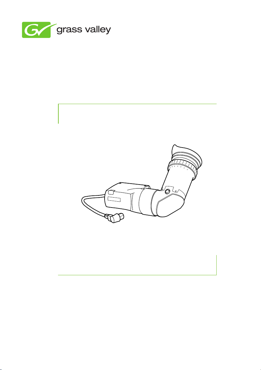
LDK 5302/60
User’s Guide
3922 496 49001 September 2011 v3.0
2-inch HD viewfinder
Page 2

Declaration of Conformity
We, Grass Valley Nederland B.V., Kapittelweg 10, 4827 HG Breda, The Netherlands,
declare under our sole responsibility that this product is in compliance with the
following standards:
- EN60065 : Safety
- EN55103-1: EMC (Emission)
- EN55103-2: EMC (Immunity)
following the provisions of:
a. the Low Voltage directive 2006/95/EC
b. the EMC directive 2004/108/EC
FCC Class A Statement
This product generates, uses, and can radiate radio frequency energy and if not
installed and used in accordance with the instructions, may cause interference to
radio communications.
It has been tested and found to comply with the limits for a class A digital device
pursuant to part 15 of the FCC rules, which are designed to provide reasonable
protection against such interference when operated in a commercial environment.
Operation of this product in a residential area is likely to cause interference in which
case the user at his own expense will be required to take whatever measures may
be required to correct the interference.
Copyright
Copyright Grass Valley Nederland B.V. 2011. Copying of this document and giving it
to others, and the use or communication of the contents thereof, are forbidden
without express authority. Offenders are liable to the payment of damages. All rights
are reserved in the event of the grant of a patent or the registration of a utility model
or design. Liable to technical alterations in the course of further development.
Trademarks
Grass Valley is a trademark of Grass Valley, Inc. All other tradenames referenced are
service marks, trademarks, or registered trademarks of their respective companies.
Website
Visit the Grass Valley public website to download the latest user’s guide updates and
additional information about your broadcast product: www.grassvalley.com
Page 3

Table of contents
Chapter 1 – Installation
1.1 Mounting the viewfinder . . . . . . . . . . . . . . . . . . . . . . . . . . . 11
1.1.1 Mounting viewfinder and microphone holder . . . . . . . 11
1.1.2 Positioning the viewfinder. . . . . . . . . . . . . . . . . . . . . . 12
1.2 Viewfinder accessories . . . . . . . . . . . . . . . . . . . . . . . . . . . . . 13
1.2.1 LDK 5390/00 Wide angle eyepiece . . . . . . . . . . . . . . . 13
1.2.2 LDK 5390/10 Left eye adaptor. . . . . . . . . . . . . . . . . . . 14
Chapter 2 – Operation
2.1 Controls . . . . . . . . . . . . . . . . . . . . . . . . . . . . . . . . . . . . . . . . . 15
2.1.1 Tally on/off switch . . . . . . . . . . . . . . . . . . . . . . . . . . . . 15
2.1.2 Zebra (exposure indication) . . . . . . . . . . . . . . . . . . . . . 16
2.1.3 VF option switch . . . . . . . . . . . . . . . . . . . . . . . . . . . . . 16
2.1.4 Viewfinder picture quality . . . . . . . . . . . . . . . . . . . . . . 16
2.1.5 Dioptre adjustment . . . . . . . . . . . . . . . . . . . . . . . . . . . 16
2.2 Viewfinder markers and indicators . . . . . . . . . . . . . . . . . . . 16
2.2.1 Screen markers . . . . . . . . . . . . . . . . . . . . . . . . . . . . . . 17
2.2.2 Screen indicators. . . . . . . . . . . . . . . . . . . . . . . . . . . . . 17
2.2.3 Gain preset indicators . . . . . . . . . . . . . . . . . . . . . . . . . 18
2.2.4 Top indicators . . . . . . . . . . . . . . . . . . . . . . . . . . . . . . . 18
2.2.5 Color temperature indicators. . . . . . . . . . . . . . . . . . . . 19
2.2.6 Non-standard indicator (!) . . . . . . . . . . . . . . . . . . . . . . 19
2.3 Focussing . . . . . . . . . . . . . . . . . . . . . . . . . . . . . . . . . . . . . . . . 20
Chapter 3 – Specifications
3.1 Technical specifications . . . . . . . . . . . . . . . . . . . . . . . . . . . . 21
3.1.1 General . . . . . . . . . . . . . . . . . . . . . . . . . . . . . . . . . . . . 21
3.2 Connectors. . . . . . . . . . . . . . . . . . . . . . . . . . . . . . . . . . . . . . . 22
3.2.1 Viewfinder connector (lead). . . . . . . . . . . . . . . . . . . . . 22
LDK 5302/60 2-inch HD viewfinder User’s Guide (v3.0) 3
Page 4

End-of-life product recycling
Grass Valley’s innovation and excellence in product design also extends to the
programs we’ve established to manage the recycling of our products. Grass Valley
has developed a comprehensive end-of-life product take back program for recycle or
disposal of end-of-life products. Our program meets the requirements of the
European Union’s WEEE Directive and in the United States from the Environmental
Protection Agency, individual state or local agencies.
Grass Valley’s end-of-life product take back program assures proper disposal by use
of Best Available Technology. This program accepts any Grass Valley branded
equipment. Upon request, a Certificate of Recycling or a Certificate of Destruction,
depending on the ultimate disposition of the product, can be sent to the requester.
Grass Valley will be responsible for all costs associated with recycling and disposal,
including freight, however you are responsible for the removal of the equipment
from your facility and packing the equipment ready for pickup.
For further information on the Grass Valley product take back system please contact
Grass Valley at + 800 80 80 20 20 or +33 1 48 25 20 20 from most other countries.
In the US and Canada please call 800-547-8949 or 530-478-4148. Ask to be
connected to the EH&S Department. In addition, information concerning Grass
Valley’s environmental policy can be found at:
www.grassvalley.com/about/environmental-policy
4 LDK 5302/60 2-inch HD viewfinder User’s Guide (v3.0)
Page 5

Packing/Unpacking
Inspect the shipping container for evidence of damage immediately after receipt. If
the shipping container or cushioning material is damaged, it should be kept until the
contents of the shipment have been checked for completeness and the unit has
been checked mechanically and electrically.
The shipping container should be placed upright and opened from the top. Remove
the cushioning material and lift out the contents.
The contents of the shipment should be checked against the packing list. If the
contents are incomplete, if there is mechanical damage or defect, or if the unit does
not perform correctly when unpacked, notify your Grass Valley sales or service
centre within eight days.
If the shipping container shows signs of damage or stress, notify the carrier as well.
If the unit is being returned to Grass Valley for servicing, try to use the containers
and materials of the original packaging. Attach a tag indicating the type of service
required, return address, model number, full serial number and the return number
which will be supplied by your Grass Valley service centre.
If the original packing can no longer be used, the following general instructions
should be used for repacking with commercially available materials:
• Wrap unit in heavy paper or plastic.
• Use a strong shipping container.
• Use a layer of shock-absorbing material around all sides of the unit to provide
firm cushioning and prevent movement inside container.
• Seal shipping container securely.
• Mark shipping container FRAGILE to ensure careful handling.
LDK 5302/60 2-inch HD viewfinder User’s Guide (v3.0) 5
Page 6

Important information
Read this information carefully before installing this equipment and retain them for
future reference. Read and comply with the warning and caution notices that appear
in the manual. Any changes or modifications not expressly approved in this manual
could void your authority to operate this equipment.
Safety Summary
This information is intended as a guide for trained and qualified personnel who are
aware of the dangers involved in handling potentially hazardous electrical/electronic
equipment. It is not intended to contain a complete list of all safety precautions
which should be observed by personnel in using this or other electronic equipment.
The installation of this equipment involves risks both to personnel and equipment
and must be performed only by qualified personnel exercising due care.
During installation and operation of this equipment, local building safety and fire
protection standards must be observed.
Whenever it is likely that safe operation is impaired, the apparatus must be made
inoperative and secured against any unintended operation. The appropriate servicing
authority must then be informed. For example, safety is likely to be impaired if the
apparatus fails to perform the intended function or shows visible damage.
The unit is protected according to IEC 60529 IPX54 (dust-protected and resistant to
splashing water).
Warnings
Warnings indicate danger that requires correct procedures or practices to prevent
death or injury to personnel.
• Do not modify this equipment;
• Do not use any accessories other than those recommended by the
manufacturer;
• There are no user serviceable parts inside. Refer servicing to qualified
personnel only or contact your local Grass Valley representative;
6 LDK 5302/60 2-inch HD viewfinder User’s Guide (v3.0)
Page 7

Cautions
Cautions indicate procedures or practices that should be followed to prevent
damage or destruction to equipment or property.
• Do not subject the unit to severe shocks or vibration;
• Do not expose the unit to extremes of temperature;
• To prevent risk of overheating, ventilate the product correctly;
LDK 5302/60 2-inch HD viewfinder User’s Guide (v3.0) 7
Page 8

Wichtige Hinweise
Lesen Sie bitte diese Hinweise genau bevor Sie diese Apparatur installieren und
erhalten Sie Sie für künftiges Nachslagen. Beachten und Lesen Sie alle mit
“Achtung” und “Vorsicht” gekennzeichneten Warnhinweise.
Änderungen haben zur Folge, dass die Garantie ungültig wird und der Benutzer für
etwaige durch die veränderte Ausrüstung verursachte Störungen haftbar gemacht
werden könnte.
Sicherheit (Zusammenfassung)
Diese Informationen sind als Leitfaden für qualifiziertes Fachpersonal gedacht, das
die Gefahren beim Umgang mit potenziell gefährlicher elektrischer/elektronischer
Ausrüstung kennt. Es handelt sich dabei nicht um eine vollständige
Zusammenstellung aller Sicherheitsvorkehrungen, die beim Gebrauch dieser oder
anderer elektronischer Geräte zu beachten sind.
Die Montage, Wartung und Instandsetzung dieser Ausrüstung ist mit Risiken für
Personal und Ausrüstung verbunden und darf nur von qualifiziertem Personal
vorgenommen werden, wobei mit der nötigen Sorgfalt vorzugehen ist.
Beim Einbau und Betrieb dieser Ausrüstung müssen die örtlichen
Gebäudesicherheits- und Brandschutzvorschriften beachtet werden.
Wenn eine Beeinträchtigung des sicheren Betriebs wahrscheinlich ist, muss das
Gerät außer Betrieb gesetzt und gegen ungewollten Betrieb gesichert werden. Dann
muss der zuständige Kundendienst benachrichtigt werden. Eine Beeinträchtigung
der Sicherheit ist zum Beispiel dann wahrscheinlich, wenn das Gerät nicht wie
vorgesehen funktioniert oder einen sichtbaren Schaden aufweist.
Dieser Ausrüstung ist gemäß IE 60529 IPX54 geschützt (Staub- und
Spritwassergeschützt).
Vorsicht
Mit “Vorsicht” wird auf eine Gefahr hingewiesen, die korrekte Arbeits- oder
Verfahrensweisen erfordert, um Tod oder Verletzung zu verhindern.
• An dieser Ausrüstung dürfen keine Änderungen vorgenommen werden;
• Es sollen nur von den Hersteller empfohlene Zubehöre verwendet werden;
• Dieses Produkt enthält keine Anwenderteile. Reparatur und Wartung nur von
qualifiziertem Fachpersonal vornehmen lassen oder nehmen Sie Kontakt auf
mit Ihrem Grass Valley Vertretene;
8 LDK 5302/60 2-inch HD viewfinder User’s Guide (v3.0)
Page 9

Achtung
Mit “Achtung” werden Arbeitsanweisungen gekennzeichnet, die zu befolgen sind,
um eine Beschädigung oder Zerstörung der Ausrüstung bzw. von Eigentum zu
verhindern.
• Dieses Produkt darf nicht an extremen stöße oder Zittern ausgesetzt werden;
• Dieses Produkt darf nicht an extremen Temperaturen ausgesetzt werden;
• Um einer Überhitzungsgefahr vorzubeugen, ist das Produkt korrekt zu
belüften.
LDK 5302/60 2-inch HD viewfinder User’s Guide (v3.0) 9
Page 10

10 LDK 5302/60 2-inch HD viewfinder User’s Guide (v3.0)
Page 11

Chapter 1 - Installation
Note
Chapter 1
Installation
1.1 Mounting the viewfinder
1.1. 1 Mounting viewfinder and microphone holder
To mount the viewfinder proceed as follows:
1. Loosen locking ring (1) of viewfinder support bracket (2) at the front of the
camera handgrip. (As seen from the rear of the camera, turning the locking ring
counterclockwise moves it towards the handgrip.)
2. Slide the viewfinder onto the viewfinder support bracket.
3. Tighten the locking ring (1) by turning it clockwise (as seen from rear) so that
the viewfinder is mounted securely to the support.
4. Connect the viewfinder cable to the viewfinder connector socket (6) at the top
right of the camera.
5. Slide the microphone holder (4) onto the viewfinder and secure with the
knurled screw (5).
Always fit the microphone holder as it functions as a safety stop for the viewfinder.
LDK 5302/60 2-inch HD viewfinder User’s Guide (v3.0) 11
Page 12

6. To improve the comfort of the skin contact when using the viewfinder, fit the
3
2
1
5
6
4
eye piece cover (3) to the rubber eyepiece. Spare eye piece covers (ordering
number 3922 405 00461) are available via your Grass Valley representative.
1.1. 2 Positioning the viewfinder
The horizontal position of the viewfinder can be adjusted as follows to suit your
requirements:
1. Loosen the locking ring (1). (As seen from the rear of the camera, turning the
locking ring counterclockwise moves it towards the handgrip.)
2. Slide the viewfinder horizontally along the rail to the desired position.
3. Tighten the locking ring (1) by turning clockwise.
The dioptre hood and eyepiece of the viewfinder can be rotated vertically.
The viewfinder can be positioned backwards and forwards along the camera axis.
Loosen the support bracket round bar retaining lever (2) and slide the round bar (3)
forwards or backwards. When the desired position is reached tighten the support
bracket round bar retaining lever (2) again.
Chapter 1 - Installation
12 LDK 5302/60 2-inch HD viewfinder User’s Guide (v3.0)
Page 13

To use the viewfinder at a distance press the button (4) below or above the eyepiece
5
4
2
1
3
tube and swing it free of the associated clip (5). The display can now be seen from
further away.
1.2 Viewfinder accessories
1.2 .1 LDK 5390/00 Wide angle eyepiece
If you regularly use the viewfinder at a distance, for example, when you use the
camera in the hand-held position, it is recommended that you fit the optionally
available wide angle eyepiece. To fit the wide angle eyepiece proceed as follows:
1. Hold the eyepiece (1) securely.
2. Press the button (2) below the eyepiece tube and swing it free of the button
clip (3).
3. Press the button (4) above the eyepiece tube and remove the eyepiece.
Chapter 1 - Installation
LDK 5302/60 2-inch HD viewfinder User’s Guide (v3.0) 13
Page 14

4. Fit the wide angle eyepiece (1) to the two clips (3) ensuring that they both click
4
2
1
3
2
1
3
into place.
1.2 .2 LDK 5390/10 Left eye adaptor
A left eye adaptor is optionally available to allow the viewfinder to be used with the
left eye. Before mounting the viewfinder onto the camera, attach the left eye adaptor
(1) to the viewfinder and secure it using the screw (2). Do not forget to mount the
microphone support bracket (3) at the end of the left eye adaptor.
Chapter 1 - Installation
14 LDK 5302/60 2-inch HD viewfinder User’s Guide (v3.0)
Page 15

Chapter 2
Crisp
Tally Zebra Option
Contr. Bright.
Tally on/off
switch
Zebra on/off
switch
VF option
switch
Crispening
control
Contrast
control
Brightness
control
Dioptre
adjustment ring
Operation
2.1 Controls
Set up the viewfinder according to your own preferences; adjust viewing
parameters, select markers, message boxes and on-screen display times in the VF
menu.
Chapter 2 - Operation
2.1.1 Tally on/off switch
LDK 5302/60 2-inch HD viewfinder User’s Guide (v3.0) 15
The red Tally indicators at the front of the viewfinder and at the rear of the handgrip
light to indicate that the camera is On Air. The Tally switch is used to control the Tally
indicators at the front of the viewfinder and the rear of the handgrip. When this
switch is set to the Off position, the Tally indicator does not light even when the
camera is On Air.
When the camera is On Air, the REC indicator in the viewfinder lights. When the
studio ISO signal is received, the MEDIA indicator lights.
Page 16

2.1.2 Zebra (exposure indication)
ND/RE
BATT
MEDIAREC
++
+
-
AW2AW1AWFL7.55.63.2
FOC+
4.7
!
45
A2
23
Safe area
marker
Zoom
indicator
Centre
cross
Message
box
Iris indicator or
Focus indicator
Cadre marker
Box downright:
Filter indicator or
Quality of
service indicator
Gain preset
indicators
To p
indicators
Non-standard
indicator
Color temperature
indicators
The Zebra function displays a zebra pattern in the viewfinder in areas where
highlights occur. This diagonal line pattern warns you that the area affected has risen
above a preset level of the full scale video exposure. Go to the VF > Zebra menu to
turn Zebra on or off and to set the video levels at which the Zebra function works.
2.1.3 VF option switch
Not used.
2.1.4 Viewfinder picture quality
Adjust the Brightness and Contrast controls according to your preferences. If you
wish, use the Crispening (peaking) control to adjust the sharpness of the viewfinder
picture (reduce the crispening when the gain is set to +++).
2.1.5 Dioptre adjustment
The dioptre of the viewfinder can be adjusted to suit your eyesight by turning the
Dioptre adjustment ring. The range of the dioptre is +1 to -3.
Chapter 2 - Operation
2.2 Viewfinder markers and indicators
16 LDK 5302/60 2-inch HD viewfinder User’s Guide (v3.0)
Page 17

2.2.1 Screen markers
Note
Go to the VF menu to select the markers you wish to see in the viewfinder screen.
The following markers can be set up:
Marker Description
Cadre marker A dotted white line or a shaded area that shows the limits
Safe area marker Encloses an area that represents 80% of the whole
Message box Displays information messages.
Centre cross Marks the centre of the picture
2.2.2 Screen indicators
Go to the VF menu to select the indicators you wish to see in the viewfinder screen.
The following indicators can be set up:
Indicator Description
Zoom indicator Indicates the percentage to which the lens has been
Iris indicator Indicates the iris opening (F -value) of the lens. Typical
Focus indicator Indicates the percentage of the focus distance range from
Filter indicator Indicates the selected optical filter.
Quality of Service
indicator
Chapter 2 - Operation
of a 4:3 (15:9 or 14:9) picture.
viewfinder picture area. This is the minimum area seen on
a TV-set.
zoomed out or in, ranging from 0 (wide) to 99 (tele). It
shows 50 if the lens does not support this feature.
range is 1.4 to 25. Displays ‘Closed’ when the lens is
closed or capped.
0 (close-up) to 99 (infinity).
When an HD Wireless system is in use, this indicator
shows the quality of the wireless transmission link.
Either the Iris indicator or the Focus indicator can be displayed in the viewfinder.
When one of the indicators is turned on, the other is automatically turned off.
LDK 5302/60 2-inch HD viewfinder User’s Guide (v3.0) 17
Page 18

Note
When using an HD Wireless system Go to the VF > Box Downright item to select
the Filter or the Quality of Service indicator to be displayed in the viewfinder screen.
You can also switch off the indicator.
2.2.3 Gain preset indicators
The gain preset indicators at the top of the viewfinder light as follows:
Indicator Function
– Gain is – (-6 dB or -3 dB)
Off Gain is 0 dB
+ Gain is + (3 dB, 6 dB or 9 dB)
++ Gain is ++ (6 dB, 9 dB or 12 dB)
+ and ++ Gain is +++ (12 dB)
2.2.4 Top indicators
The top indicators provide status information about the camera:
Chapter 2 - Operation
Indicator Function
REC Lights when the camera is On Air.
MEDIA Lights when studio ISO recording has started.
BATT Lights if the camera supply voltage is less than 11.5 V
(when using a battery or an external supply).
ND/RE Lights when an ND optical filter or the range extender is
selected.
FOC+ Lights when the focus assist function is on.
18 LDK 5302/60 2-inch HD viewfinder User’s Guide (v3.0)
Page 19

2.2.5 Color temperature indicators
The color temperature indicators light as follows:
Indicator Function
3.2 Lights when preset temperature of 3200 K is selected.
5.6 Lights when preset temperature of 5600 K is selected.
7.5 Lights when preset temperature of 7500 K is selected.
AWFL Lights when a memory for fluorescent light (FL50 or
FL60) is selected.
AW1 Lights when auto white balance memory 1 is selected.
AW2 Lights when auto white balance memory 2 is selected.
2.2.6 Non-standard indicator (!)
The non-standard video settings indicator (!) lights when one of the following
conditions occur:
• exposure time is not set to the nominal value.
• black stretch is on.
• extended auto iris is on.
• AWC (continuous automatic white balance) or FL color temperature is on.
Chapter 2 - Operation
LDK 5302/60 2-inch HD viewfinder User’s Guide (v3.0) 19
Page 20

2.3 Focussing
A focus assist function can be switched on or off in the VF menu. This function adds
motion in the viewfinder to objects in sharp focus. The FOC+ indicator in the
viewfinder lights when this function is on.
The viewfinder zoom function is another feature that helps you focus. This function
enlarges the centre of the viewfinder image. Choose one of the following buttons
and the way it operates (momentary or toggle) to control this function in the Install
menu:
• The VTR button on the camera.
• The VTR button on the lens.
• The RET switch on a zoom control when a large lens adaptor is used.
When the viewfinder zoom function is in use, many of the viewfinder markers are
switched off to improve the clarity of the display. The FOC+ indicator in the
viewfinder flashes when the viewfinder zoom function is active.
Chapter 2 - Operation
20 LDK 5302/60 2-inch HD viewfinder User’s Guide (v3.0)
Page 21

Chapter 3
Specifications
3.1 Technical specifications
3.1.1 General
Dimensions (L X W x H) 255 x 126 x 135 mm
Weight (approx.) 0.74 kg (1.6 lbs) without microphone and mic holder
Operating temperatures -20 to +45 °C (-4 to +113 °F)
Storage temperatures -25 to +60 °C (-13 to +140 °F)
Operating humidity 93%
Power supply +10.5 VDC to 17 VDC (supplied by the camera)
Power consumption (max.) 10 W (supplied by the camera head)
Display type 2-inch CRT high resolution type
Linearity and geometry Distortion: 1% within a circle with a diameter of
picture height, 1.5% for outer region.
Resolution (horizontal) Min. 650 lines in centre of screen at 400 cd/m
Frequency response 5 MHz within -1 dB to +2 dB with resp. to 0.1 MHz
10 MHz - 3 dB
Peaking 0 to 12 dB at approx. 3.5 MHz
Black level stability Change of black level 1.5% with respect to white
level
Controls Brightness, Contrast and Peaking
Indicators Tally light, On-Air, Yellow On-Air, Call signal
Chapter 3 - Specifications
2
LDK 5302/60 2-inch HD viewfinder User’s Guide (v3.0) 21
Page 22

3.2 Connectors
Pin Description
1 -80 VDC
2 Not connected
3 GND
4 INTN-D (I
2
C interface)
5 Not connected
6 Not connected
7 VF video return
8 SDA-D (I
2
C interface)
9 SCL-D (I
2
C interface)
10 Not connected
Pin Description
11 GND
12 VF video
13 Pb VF video return
14 Pr VF video return
15 GND
16 +Batt (10.5 to 17 VDC)
17 -Batt (10.5 to 17 VDC)
18 Pb VF video
19 Pr VF video
20 Shield
20-pin male viewfinder connector, moulded to the viewfinder cable
(manufacturer code: Hirose HR12-14LA20P)
20
1
16
5
3.2.1 Viewfinder connector (lead)
Chapter 3 - Specifications
22 LDK 5302/60 2-inch HD viewfinder User’s Guide (v3.0)
Page 23

LDK 5302/60 2-inch HD viewfinder User’s Guide (v3.0) 23
Page 24

Printed in The Netherlands Copyright Grass Valley Nederland B.V. 2011
 Loading...