

Page 1

User’s Guide
3922 496 30081
version 2
LDK 500
CAMERA SYSTEM
Page 2

LDK 500 User’s Guide iii
Table of Contents
Chapter 1 – Introduction
Technology . . . . . . . . . . . . . . . . . . . . . . . . . . . . . . . . . . . . . . . . . . . . . . . . . . . . . . 1-1
Frame Transfer DPM sensor . . . . . . . . . . . . . . . . . . . . . . . . . . . . . . . . . . . . . . . 1-1
Digital Processing . . . . . . . . . . . . . . . . . . . . . . . . . . . . . . . . . . . . . . . . . . . . . . . 1-2
Film-like characteristics . . . . . . . . . . . . . . . . . . . . . . . . . . . . . . . . . . . . . . . . . . . 1-2
Features . . . . . . . . . . . . . . . . . . . . . . . . . . . . . . . . . . . . . . . . . . . . . . . . . . . . . . . . 1-2
Specifications. . . . . . . . . . . . . . . . . . . . . . . . . . . . . . . . . . . . . . . . . . . . . . . . . . . . . 1-4
Dimensions. . . . . . . . . . . . . . . . . . . . . . . . . . . . . . . . . . . . . . . . . . . . . . . . . . . . 1-6
Accessories . . . . . . . . . . . . . . . . . . . . . . . . . . . . . . . . . . . . . . . . . . . . . . . . . . . . . . 1-7
Chapter 2 – Installation
Packing/unpacking. . . . . . . . . . . . . . . . . . . . . . . . . . . . . . . . . . . . . . . . . . . . . . . . . 2-1
Transport case . . . . . . . . . . . . . . . . . . . . . . . . . . . . . . . . . . . . . . . . . . . . . . . . . . . . 2-2
Mounting a lens . . . . . . . . . . . . . . . . . . . . . . . . . . . . . . . . . . . . . . . . . . . . . . . . . . 2-3
1.5-inch Viewfinder . . . . . . . . . . . . . . . . . . . . . . . . . . . . . . . . . . . . . . . . . . . . . . . . 2-4
Mounting viewfinder and microphone holder . . . . . . . . . . . . . . . . . . . . . . . . . . 2-4
Positioning the viewfinder . . . . . . . . . . . . . . . . . . . . . . . . . . . . . . . . . . . . . . . . 2-5
1.5-inch Viewfinder Accessories. . . . . . . . . . . . . . . . . . . . . . . . . . . . . . . . . . . . . . . 2-5
Wide angle eyepiece. . . . . . . . . . . . . . . . . . . . . . . . . . . . . . . . . . . . . . . . . . . . . 2-5
Left eye adapter . . . . . . . . . . . . . . . . . . . . . . . . . . . . . . . . . . . . . . . . . . . . . . . . 2-6
Mounting a microphone . . . . . . . . . . . . . . . . . . . . . . . . . . . . . . . . . . . . . . . . . . . . 2-7
Tripod adapter plate . . . . . . . . . . . . . . . . . . . . . . . . . . . . . . . . . . . . . . . . . . . . . . . 2-8
Adjusting the shoulder pad . . . . . . . . . . . . . . . . . . . . . . . . . . . . . . . . . . . . . . . . . . 2-9
Mounting a top light . . . . . . . . . . . . . . . . . . . . . . . . . . . . . . . . . . . . . . . . . . . . . . 2-10
Zoom controls . . . . . . . . . . . . . . . . . . . . . . . . . . . . . . . . . . . . . . . . . . . . . . . . . . . 2-11
Attaching an adapter. . . . . . . . . . . . . . . . . . . . . . . . . . . . . . . . . . . . . . . . . . . . . . 2-12
Chapter 3 – Cabling and connectors
Configurations . . . . . . . . . . . . . . . . . . . . . . . . . . . . . . . . . . . . . . . . . . . . . . . . . . . 3-2
Camera with Triax adapter . . . . . . . . . . . . . . . . . . . . . . . . . . . . . . . . . . . . . . . . 3-2
Multiple Triax cameras with C2IP network . . . . . . . . . . . . . . . . . . . . . . . . . . . . 3-2
Camera with Triax adapter and SuperXpander . . . . . . . . . . . . . . . . . . . . . . . . . 3-4
Camera connectors . . . . . . . . . . . . . . . . . . . . . . . . . . . . . . . . . . . . . . . . . . . . . . . . 3-5
Viewfinder connector . . . . . . . . . . . . . . . . . . . . . . . . . . . . . . . . . . . . . . . . . . . . 3-5
Lens connector . . . . . . . . . . . . . . . . . . . . . . . . . . . . . . . . . . . . . . . . . . . . . . . . . 3-6
Audio microphone connector . . . . . . . . . . . . . . . . . . . . . . . . . . . . . . . . . . . . . . 3-6
RS232 serial connector . . . . . . . . . . . . . . . . . . . . . . . . . . . . . . . . . . . . . . . . . . . 3-7
Page 3

LDK 500 User’s Guide iv
Triax adapter connectors . . . . . . . . . . . . . . . . . . . . . . . . . . . . . . . . . . . . . . . . . . . . 3-8
Triax connector. . . . . . . . . . . . . . . . . . . . . . . . . . . . . . . . . . . . . . . . . . . . . . . . . 3-9
CVBS output connector . . . . . . . . . . . . . . . . . . . . . . . . . . . . . . . . . . . . . . . . . . 3-9
Viewfinder / External video output connector . . . . . . . . . . . . . . . . . . . . . . . . . . 3-9
Script light power supply socket . . . . . . . . . . . . . . . . . . . . . . . . . . . . . . . . . . . 3-10
Teleprompter video output connector. . . . . . . . . . . . . . . . . . . . . . . . . . . . . . . 3-10
DC power and tally output socket. . . . . . . . . . . . . . . . . . . . . . . . . . . . . . . . . . 3-10
Audio microphone 2 connector . . . . . . . . . . . . . . . . . . . . . . . . . . . . . . . . . . . 3-11
DC power input socket . . . . . . . . . . . . . . . . . . . . . . . . . . . . . . . . . . . . . . . . . . 3-11
Audio microphone 1 connector . . . . . . . . . . . . . . . . . . . . . . . . . . . . . . . . . . . 3-12
Intercom headset connector . . . . . . . . . . . . . . . . . . . . . . . . . . . . . . . . . . . . . . 3-12
Reference input connector . . . . . . . . . . . . . . . . . . . . . . . . . . . . . . . . . . . . . . . 3-13
Tracker communications connector. . . . . . . . . . . . . . . . . . . . . . . . . . . . . . . . . 3-13
Auxiliary connector. . . . . . . . . . . . . . . . . . . . . . . . . . . . . . . . . . . . . . . . . . . . . 3-14
Chapter 4 – Operating instructions
Camera head controls . . . . . . . . . . . . . . . . . . . . . . . . . . . . . . . . . . . . . . . . . . . . . . 4-3
Viewfinder controls . . . . . . . . . . . . . . . . . . . . . . . . . . . . . . . . . . . . . . . . . . . . . . . . 4-4
Assigning functions to buttons . . . . . . . . . . . . . . . . . . . . . . . . . . . . . . . . . . . . . 4-5
Using the camera. . . . . . . . . . . . . . . . . . . . . . . . . . . . . . . . . . . . . . . . . . . . . . . . . . 4-6
Switching on the power . . . . . . . . . . . . . . . . . . . . . . . . . . . . . . . . . . . . . . . . . . 4-6
Controlling the camera . . . . . . . . . . . . . . . . . . . . . . . . . . . . . . . . . . . . . . . . . . . 4-6
Access and Security . . . . . . . . . . . . . . . . . . . . . . . . . . . . . . . . . . . . . . . . . . . . . . . . 4-7
Camera cards . . . . . . . . . . . . . . . . . . . . . . . . . . . . . . . . . . . . . . . . . . . . . . . . . . 4-7
Access control . . . . . . . . . . . . . . . . . . . . . . . . . . . . . . . . . . . . . . . . . . . . . . . . . 4-8
Camera card slot . . . . . . . . . . . . . . . . . . . . . . . . . . . . . . . . . . . . . . . . . . . . . . . 4-8
System Menu. . . . . . . . . . . . . . . . . . . . . . . . . . . . . . . . . . . . . . . . . . . . . . . . . . . . . 4-9
Entering the System menu . . . . . . . . . . . . . . . . . . . . . . . . . . . . . . . . . . . . . . . . 4-9
Finding your way . . . . . . . . . . . . . . . . . . . . . . . . . . . . . . . . . . . . . . . . . . . . . . 4-10
Leaving the System Menu . . . . . . . . . . . . . . . . . . . . . . . . . . . . . . . . . . . . . . . . 4-10
Making changes . . . . . . . . . . . . . . . . . . . . . . . . . . . . . . . . . . . . . . . . . . . . . . . 4-11
Undoing changes . . . . . . . . . . . . . . . . . . . . . . . . . . . . . . . . . . . . . . . . . . . . . . 4-11
Viewfinder preferences . . . . . . . . . . . . . . . . . . . . . . . . . . . . . . . . . . . . . . . . . . . . 4-12
Viewfinder picture quality . . . . . . . . . . . . . . . . . . . . . . . . . . . . . . . . . . . . . . . . 4-12
Video level indication . . . . . . . . . . . . . . . . . . . . . . . . . . . . . . . . . . . . . . . . . . . 4-12
Tally indicators . . . . . . . . . . . . . . . . . . . . . . . . . . . . . . . . . . . . . . . . . . . . . . . . 4-12
Viewfinder markers. . . . . . . . . . . . . . . . . . . . . . . . . . . . . . . . . . . . . . . . . . . . . 4-12
Lens preferences . . . . . . . . . . . . . . . . . . . . . . . . . . . . . . . . . . . . . . . . . . . . . . . . . 4-13
Lens type . . . . . . . . . . . . . . . . . . . . . . . . . . . . . . . . . . . . . . . . . . . . . . . . . . . . 4-13
Auto iris . . . . . . . . . . . . . . . . . . . . . . . . . . . . . . . . . . . . . . . . . . . . . . . . . . . . . 4-13
Extended Iris . . . . . . . . . . . . . . . . . . . . . . . . . . . . . . . . . . . . . . . . . . . . . . . . . . 4-13
Lens indicators . . . . . . . . . . . . . . . . . . . . . . . . . . . . . . . . . . . . . . . . . . . . . . . . 4-13
Page 4

LDK 500 User’s Guide v
Video preferences . . . . . . . . . . . . . . . . . . . . . . . . . . . . . . . . . . . . . . . . . . . . . . . . 4-14
Standard settings . . . . . . . . . . . . . . . . . . . . . . . . . . . . . . . . . . . . . . . . . . . . . . 4-14
Test signal . . . . . . . . . . . . . . . . . . . . . . . . . . . . . . . . . . . . . . . . . . . . . . . . . . . 4-14
Gain selection. . . . . . . . . . . . . . . . . . . . . . . . . . . . . . . . . . . . . . . . . . . . . . . . . 4-15
Optical filter selection . . . . . . . . . . . . . . . . . . . . . . . . . . . . . . . . . . . . . . . . . . . 4-15
Colour temperature selection . . . . . . . . . . . . . . . . . . . . . . . . . . . . . . . . . . . . . 4-16
Exposure time. . . . . . . . . . . . . . . . . . . . . . . . . . . . . . . . . . . . . . . . . . . . . . . . . 4-18
Black stretch. . . . . . . . . . . . . . . . . . . . . . . . . . . . . . . . . . . . . . . . . . . . . . . . . . 4-21
Auto skin contour. . . . . . . . . . . . . . . . . . . . . . . . . . . . . . . . . . . . . . . . . . . . . . 4-21
Freeze frame . . . . . . . . . . . . . . . . . . . . . . . . . . . . . . . . . . . . . . . . . . . . . . . . . 4-22
Effects . . . . . . . . . . . . . . . . . . . . . . . . . . . . . . . . . . . . . . . . . . . . . . . . . . . . . . 4-23
Managing files. . . . . . . . . . . . . . . . . . . . . . . . . . . . . . . . . . . . . . . . . . . . . . . . . . . 4-23
Scene files . . . . . . . . . . . . . . . . . . . . . . . . . . . . . . . . . . . . . . . . . . . . . . . . . . . 4-24
Operator files . . . . . . . . . . . . . . . . . . . . . . . . . . . . . . . . . . . . . . . . . . . . . . . . . 4-24
Standard files . . . . . . . . . . . . . . . . . . . . . . . . . . . . . . . . . . . . . . . . . . . . . . . . . 4-24
Customer standard files . . . . . . . . . . . . . . . . . . . . . . . . . . . . . . . . . . . . . . . . . 4-24
User levels . . . . . . . . . . . . . . . . . . . . . . . . . . . . . . . . . . . . . . . . . . . . . . . . . . . . . . 4-25
Selecting the user level . . . . . . . . . . . . . . . . . . . . . . . . . . . . . . . . . . . . . . . . . . 4-25
Smart-Touch™ . . . . . . . . . . . . . . . . . . . . . . . . . . . . . . . . . . . . . . . . . . . . . . . . . . 4-26
Triax adapter controls . . . . . . . . . . . . . . . . . . . . . . . . . . . . . . . . . . . . . . . . . . . . . 4-27
Powering the camera . . . . . . . . . . . . . . . . . . . . . . . . . . . . . . . . . . . . . . . . . . . 4-28
Selecting monitoring signals . . . . . . . . . . . . . . . . . . . . . . . . . . . . . . . . . . . . . . 4-28
Using audio . . . . . . . . . . . . . . . . . . . . . . . . . . . . . . . . . . . . . . . . . . . . . . . . . . 4-28
Intercom. . . . . . . . . . . . . . . . . . . . . . . . . . . . . . . . . . . . . . . . . . . . . . . . . . . . . 4-29
Communication . . . . . . . . . . . . . . . . . . . . . . . . . . . . . . . . . . . . . . . . . . . . . . . 4-30
Chapter 5 – Menu structure
Menu structure . . . . . . . . . . . . . . . . . . . . . . . . . . . . . . . . . . . . . . . . . . . . . . . . . . . 5-2
Main (top) menu . . . . . . . . . . . . . . . . . . . . . . . . . . . . . . . . . . . . . . . . . . . . . . . 5-2
Where to find a function . . . . . . . . . . . . . . . . . . . . . . . . . . . . . . . . . . . . . . . . . 5-6
Page 5

LDK 500 User’s Guide vi
Page 6

Introduction 1-1
Chapter 1
Introduction
This section outlines the technology used in the camera system and describes how this
translates into a practical, useable camera. It lists the main features of the camera.
Contents
Technology . . . . . . . . . . . . . . . . . . . . . . . . . . . . . . . . . . . . . . . . . . . . . . . . . . . . . . 1-1
Frame Transfer DPM sensor . . . . . . . . . . . . . . . . . . . . . . . . . . . . . . . . . . . . . . . 1-1
Digital Processing . . . . . . . . . . . . . . . . . . . . . . . . . . . . . . . . . . . . . . . . . . . . . . . 1-2
Film-like characteristics . . . . . . . . . . . . . . . . . . . . . . . . . . . . . . . . . . . . . . . . . . . 1-2
Features . . . . . . . . . . . . . . . . . . . . . . . . . . . . . . . . . . . . . . . . . . . . . . . . . . . . . . . . 1-2
Specifications. . . . . . . . . . . . . . . . . . . . . . . . . . . . . . . . . . . . . . . . . . . . . . . . . . . . . 1-4
Dimensions. . . . . . . . . . . . . . . . . . . . . . . . . . . . . . . . . . . . . . . . . . . . . . . . . . . . 1-6
Accessories . . . . . . . . . . . . . . . . . . . . . . . . . . . . . . . . . . . . . . . . . . . . . . . . . . . . . . 1-7
1.1 Technology
The camera head uses three 2/3-inch CCD sensors. It is available with DPM, FT, IT or
ITW type sensors. A range of adapters can be connected to the head making a flexible
camera system that is equally at home in the studio or out on location in an OB
environment.
1.1.1 Frame Transfer DPM sensor
The Frame Transfer CCD DPM sensor offers superior performance and can handle
highlights of up to 600%. The 2/3-inch sensors have a high dynamic range and high
linear sensitivity over all camera lens apertures. Frame Transfer technology ensures that
there is no lag nor smear. The Frame Transfer DPM sensor uses Dynamic Pixel
Management which allows the format of the sensors to be switched between 4:3 and
16:9 aspect ratios at the touch of a switch without loss of horizontal or vertical
resolution. The 1000 pixels per line in both formats ensures that there is no loss in the
horizontal viewing angle but also ensures high resolution in the red, green and blue
channels.
Page 7

Introduction | Features 1-2
1.1.2 Digital Processing
The advanced digital processing of the camera is based on 14-bit A/D converters and
more than 20-bit internal processing. Two DSPs combine all major camera functions in
the digital domain, including knee, gamma, contour, matrix and colour correction.
The intelligent continuous automatics facility provides automatic control of black levels
and black shading. Each sensor provides black reference signals that are used to
monitor temperature changes. This means that continuous automatic correction is
applied without operator intervention.
The digital contour processing uses full amplitude video RGB signals via an extended
dynamic range contour circuit.
Colorimetry is selected by means of a variable 6-point digital matrix or via preset
matrices. Digital gamma circuits provide a wide range of standardised gamma curves
and enable soft contrast in black scenes to be enhanced, together with hard contrast
and saturated colour in bright scenes. The matrix and gamma sequence is software
programmable for precise colour matching.
1.1.3 Film-like characteristics
The pivoting knee circuit adapts both the knee point and the compression ratio
according to the highlight content of the picture to emulate the softly limiting
S-shaped transfer characteristics of film. Digital True Colour Knee circuitry maintains
the correct hue for compressed highlights, reproducing colours faithfully, even
overexposed skin tones.
Digital contrast circuitry provides a black stretch function for more detail in black areas
and a black press function for improving the contrast impression by simulating the
S-curve of film.
1.2 Features
• Three 2/3-inch switchable DPM FT sensors ensure no vertical smear.
• DPM Frame Transfer sensors with 1000 horizontal pixels in 4:3 and 16:9 aspect
ratios, and the same number of vertical lines in both formats. No change in
horizontal viewing angle - so no optical wide angle convertors required.
• 14-bit digital processing with unique software programmable video path.
• Superior all digital highlight handling with a wide dynamic range.
• Unique circuitry for pivoting knee and True Colour Knee.
• Wide range of presets and variable 6-point digital matrix assure accurate colour
matching.
• Fluorescent light matrix
• Digital gamma with unique standard preset values and highest accuracy.
• Digital contour with an extensive range of parameters.
• Advanced contour correction includes two automatic skin settings.
Page 8

Introduction | Features 1-3
• Intelligent Continuous Automatics black levels, black shading and video levels - no
set-up time required.
• Digital contrast with standard black stretch and black press.
• International standard 2/3-inch lens interface.
• Optical servo-controlled, four-position neutral density filter wheel.
• Optical servo-controlled, effect filter wheel.
• Electronic colour filter for creating a special look (warm/cold) for a scene, or for a
smooth colour temperature control around the white balance setting.
• Camera card for personal settings and security.
• Owner's card for setting user levels, and for copying and storing control settings.
• Protected, easy-to-operate controls and switches with read-out of all settings.
• Viewfinder status read-out of primary camera functions.
• Clean scan feature allows capture of computer and other monitor pictures.
• Digital RS232 serial interface to PC.
• Colour corrector for special effects.
• Digital effect filters for gradient and soft focus.
• Freeze frame for easier configuration.
• Digital zoom control for digital lenses.
• Zoom control handgrip makes awkward shots easy.
Options
• Zoom control handgrip makes awkward shots easy.
• Transport case.
• Smart-Touch gives the operator instant, one-button access to 14 pre-defined
shooting characteristics.
Page 9

Introduction | Specifications 1-4
1.3 Specifications
Table 1-1. LDK 300 Camera Head DPM FT version
Item Value
Power requirements supplied via adapter
Power consumption 35 W (Head + VF)
Operating temperatures -20 to +45°C (-4 to +113°F)
Storage temperatures -20 to +60°C (-4 to +140°F)
Weight (approx.) 4.8 kg incl. 1.5-inch VF and adapter
Pick-up device 3 x 2/3-inch DPM Frame Transfer CCDs
Aspect ratio switchable 4:3 and 16:9
Picture elements NTSC: 1000(h) x 498(v)
PAL: 1000(h) x 594(v)
Digital quantization 14-bit A to D
Digital signal processing 18 MHz and 36 MHz, 24-bit accuracy
Sensitivity 2000 lux at F9.0 reflectance 90%
Minimum illumination Approx. 2 lux at F 1.4 and +30 dB gain
Exposure control Down to 1/1000
Clean scanning NTSC: between 61.1 and 151.0 Hz
PAL: between 51.0 and 103.0 Hz
Optical system F1.4 with quartz filter
Optical filters Clear, 1/4 ND, 1/16 ND, 1/64 ND
Clear, 4-point star, 6-point star, soft focus
Modulation depth 70% at 5Mhz
65% at 5Mhz with Hires Digital Noise Slicer
S/N ratio Typical: 63 dB NTSC
Typical: 61 dB PAL
Registration <25 ns (0.05%) in all zones, without lens
Dynamic range >600%
Gain -6dB to +30dB in 3dB steps (user defined presets)
Viewfinder type 1.5-inch B/W
Viewfinder resolution > 600 TV lines
Page 10

Introduction | Specifications 1-5
Table 1-2. LDK 5430 Triax Adapter
Item Value
Power requirements Triax powered or 12 Vdc
Operating temperatures -20 to +45°C (-4 to +113°F)
Storage temperatures -20 to +60°C (-4 to +140°F)
Weight (approx.) 2.3 kg
Dimensions 220 (L) x 120 (W) x 205 (H) without handgrip
Triax in/out Swivel connector; Fischer, ARD, Lemo or Trilock
Triax cable length 2.400m (7,875 ft) max. with 16mm (0.63") cable
3000m with RGB long triax modification (optional)
Intercom XLR5/Tuchel with channels ENG/PROD/PROG
Video (CVBS) out Optional: 1 Vpp; 75 Ohm; BNC
Video telepromter out 1 Vpp; 75 Ohm; BNC
Monitor (Y) 1 Vpp; 75 Ohm; BNC
Reference in 1 Vpp; 75 Ohm; BNC
Tracker 11 pins Communication / Signalling
Auxilary/ Data 11 pins private data
Rear microphone in (2x) XLR 3, balanced, +48V
DC12Volts in XLR-4 male
Scriptlight power 12 Volts, 0,25A, 3-pin Fisher
DC12Volts out 4-pin Fisher 1.5 Amp.
Page 11
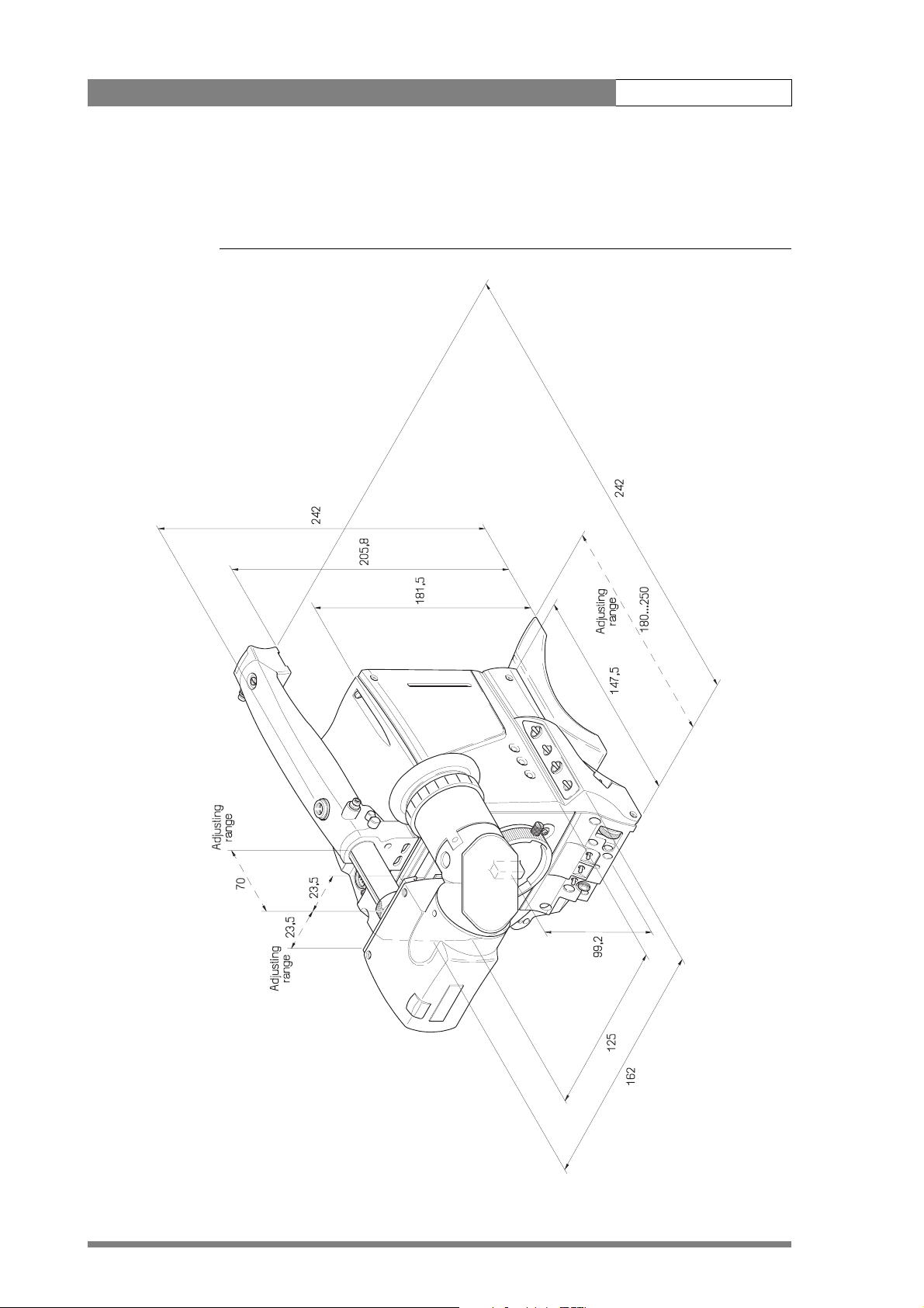
Introduction | Specifications 1-6
1.3.1 Dimensions
Figure 1-1. Dimensions
Page 12

Introduction | Accessories 1-7
1.4 Accessories
SuperXpander LDK 4482/00
5-inch viewfinder 50Hz LDK 5310/00
5-inch viewfinder 60Hz LDK 5310/50
7-inch viewfinder 50Hz LDK4016/00
7-inch viewfinder 60Hz LDK 4016/50
7-inch viewfinder support LDK 6517/00
Wide Angle adapter 1.5" vf LDK 5390/00
Sunhood for 5" VF LDK 6992/02
Raincover DVCPRO camcorder LDK 5021/01
Raincover camera with 5"VF LDK 5021/05
Raincover camera with SuperXpander LDK 6989/00
Tripod plate LDK 5031/00
Headset dynamic XLR-5 double muff LDK 8111/37
Headset dynamic XLR-5 single muff LDK 8111/51
Scriptboard with light LDK 6985/21
Transport/flightcase LDK 5020/00
Carrying bag LDK 5020/01
Camera light 20W LDK 5950/00
AC power supply LDK 4377/40
Camera (IR) remote control LDK 5200/00
Zoombox for Angenieux lenses LDK 6113/16
Zoomcontrol for Canon lenses LDK 6113/26
Zoombox for Fujinon lenses LDK 6113/36
Camera cable triax 8mm Fischer LDK 8107/yy
Camera cable triax 11mm Fischer LDK 8109/yy
Camera cable triax 14mm Fischer LDK 8112/yy
Camera cable triax 8mm ARD LDK 8116/yy
Camera cable triax 11mm ARD LDK 8117/yy
Camera cable triax 8mm LEMO LDK 8119/yy
yy: 01= 10 m, 10= 100m, 99= 990m
Page 13

Introduction | Accessories 1-8
Page 14

Installation 2-1
Chapter 2
Installation
This section describes how to physically set-up the camera system and how to attach
asccessories. Information is also provided on the connectors used in the camera and
adapter.
Contents
Packing/unpacking. . . . . . . . . . . . . . . . . . . . . . . . . . . . . . . . . . . . . . . . . . . . . . . . . 2-1
Transport case . . . . . . . . . . . . . . . . . . . . . . . . . . . . . . . . . . . . . . . . . . . . . . . . . . . . 2-2
Mounting a lens . . . . . . . . . . . . . . . . . . . . . . . . . . . . . . . . . . . . . . . . . . . . . . . . . . 2-3
1.5-inch Viewfinder . . . . . . . . . . . . . . . . . . . . . . . . . . . . . . . . . . . . . . . . . . . . . . . . 2-4
Mounting viewfinder and microphone holder . . . . . . . . . . . . . . . . . . . . . . . . . . 2-4
Positioning the viewfinder . . . . . . . . . . . . . . . . . . . . . . . . . . . . . . . . . . . . . . . . 2-5
1.5-inch Viewfinder Accessories. . . . . . . . . . . . . . . . . . . . . . . . . . . . . . . . . . . . . . . 2-5
Wide angle eyepiece. . . . . . . . . . . . . . . . . . . . . . . . . . . . . . . . . . . . . . . . . . . . . 2-5
Left eye adapter . . . . . . . . . . . . . . . . . . . . . . . . . . . . . . . . . . . . . . . . . . . . . . . . 2-6
Mounting a microphone . . . . . . . . . . . . . . . . . . . . . . . . . . . . . . . . . . . . . . . . . . . . 2-7
Tripod adapter plate . . . . . . . . . . . . . . . . . . . . . . . . . . . . . . . . . . . . . . . . . . . . . . . 2-8
Adjusting the shoulder pad . . . . . . . . . . . . . . . . . . . . . . . . . . . . . . . . . . . . . . . . . . 2-9
Mounting a top light . . . . . . . . . . . . . . . . . . . . . . . . . . . . . . . . . . . . . . . . . . . . . . . 2-9
Zoom controls . . . . . . . . . . . . . . . . . . . . . . . . . . . . . . . . . . . . . . . . . . . . . . . . . . . 2-10
Attaching an adapter. . . . . . . . . . . . . . . . . . . . . . . . . . . . . . . . . . . . . . . . . . . . . . 2-11
2.1 Packing/unpacking
Inspect the shipping container for evidence of damage immediately after receipt. If the
shipping container or cushioning material is damaged, it should be kept until the
contents of the shipment have been checked for completeness and the units have
been checked mechanically and electrically.
The shipping container should be placed upright and opened from the top. Remove
the cushioning material and lift out the contents. The contents of the shipment should
be checked against the packing list. If the contents are incomplete, if there is
mechanical damage or defect, or if the units do not perform correctly when unpacked,
notify your Thomson Broadcast and Media Solutions sales or service centre within eight
days. If the shipping container shows signs of damage or stress, notify the carrier as
well.
Page 15
Installation | Transport case 2-2
If a unit is being returned to Thomson Broadcast and Media Solutions for servicing, try
to use the containers and materials of the original packaging. Attach a tag indicating
the type of service required, return address, model number, full serial number and the
return number which will be supplied by your Thomson Broadcast and Media Solutions
service centre.
If the original packing can no longer be used, the following general instructions should
be used for repacking with commercially available materials:
1. Wrap unit in heavy paper or plastic.
2. Use strong shipping container.
3. Use a layer of shock-absorbing material around all sides of the unit to provide
firm cushioning and prevent movement inside container.
4. Seal shipping container securely.
5. Mark shipping container FRAGILE to ensure careful handling.
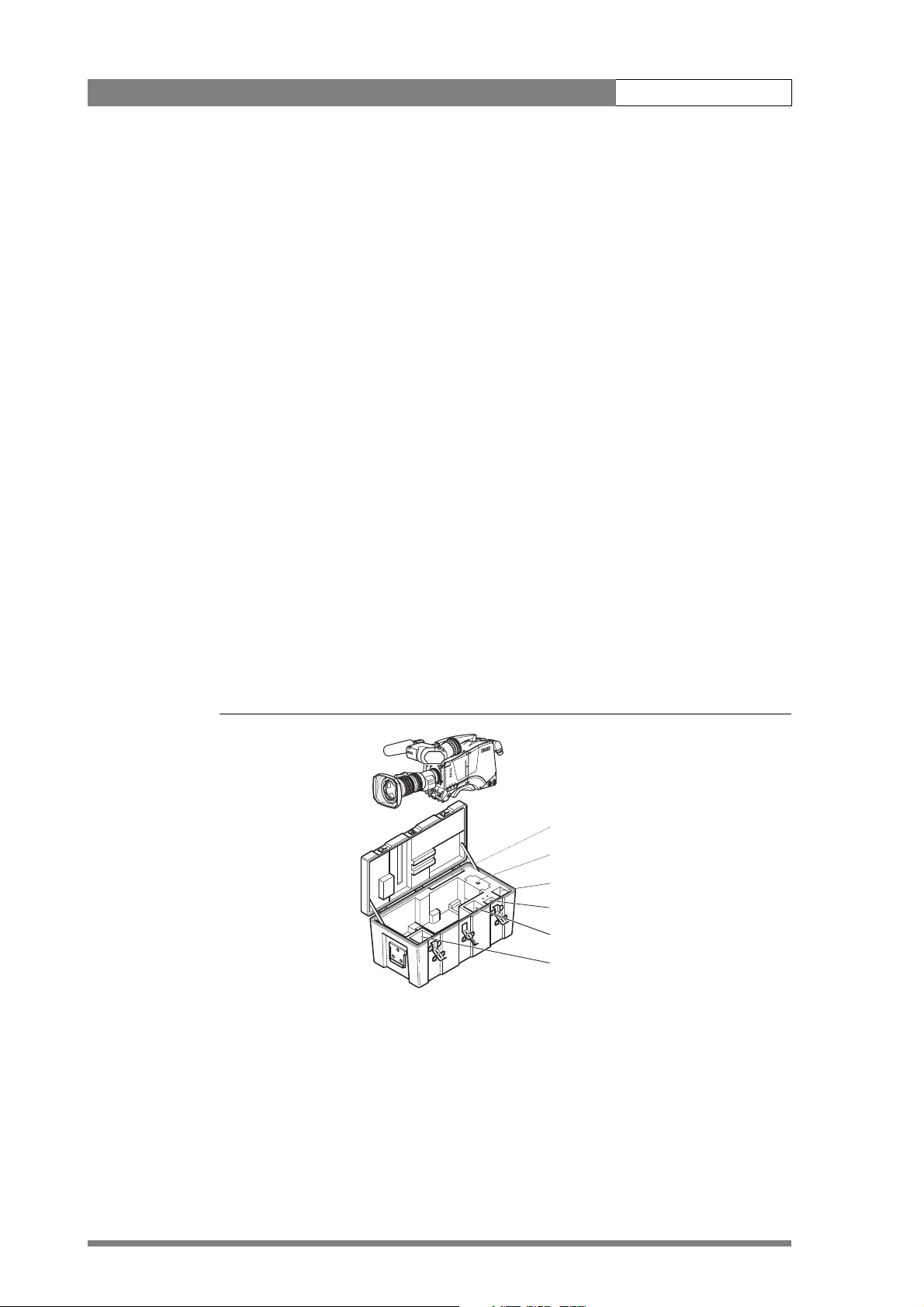
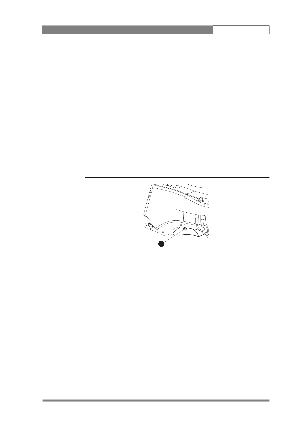
2.2 Transport case
It is important to protect your camera against damage when transporting it. To do this,
a transport case (LDK 5020/00) is optionally available for the camera, lens, viewfinder
and some accessories.
Figure 2-1. Transport case
The camera is packed in the transport case as shown in the figure above. This ensures
that the camera is not damaged during transport. Turn the 1.5-inch viewfinder
downwards so that it does not protrude above the top of the camera. Several foam
packing inserts are provided to enable different configurations of the camera to be
packed securely. These inserts are used to support the rear of the camera. Make sure
you use the correct foam insert for your particular configuration.
r
a
le
C
1
A
r
a
/4
e
l
1
C
D
N
1
B
6
1
P
/
4
1
r
a
D
t
N
S
1
C
4
6
P
/
1
6
r
a
D
t
N
S
1
D
s
u
c
o
f
t
f
o
S
Documentation
Packing inserts
Top light
Tripod plate
Battery
Additional supplies
Page 16
Installation | Mounting a lens 2-3
2.3 Mounting a lens
To attach a lens to the camera head proceed as follows:
1. Ensure that the lens locking ring (1) is in the unlocked position - turned
counterclockwise.
2. Remove the dust protection cap (2).
3. Slot the lens into the lens mount (3).
4. Turn the lens locking ring (1) clockwise to lock the lens in place.
5. Connect the lens cable to the lens connector (4) at the right side of the
camera.
6. Place the lens cable into the bottom clip at the front of the camera and clip (5)
located at the side. (Pull and twist clip to open it.)
Figure 2-2. Lens mounting
☞
1
2
bts1009
4
5
3
Caution
Do not attach a lens weighing more than 5 kg to the camera without a support.
When a new lens is fitted to the camera it may be necessary to carry out some
adjustments to optimize its use, for example, back focus or shading. For more
information about these adjustments refer to the lens manufacturer’s documentation
Note
Always mount the dust protection cap when the lens is not connected to the camera.
Page 17
Installation | 1.5-inch Viewfinder 2-4
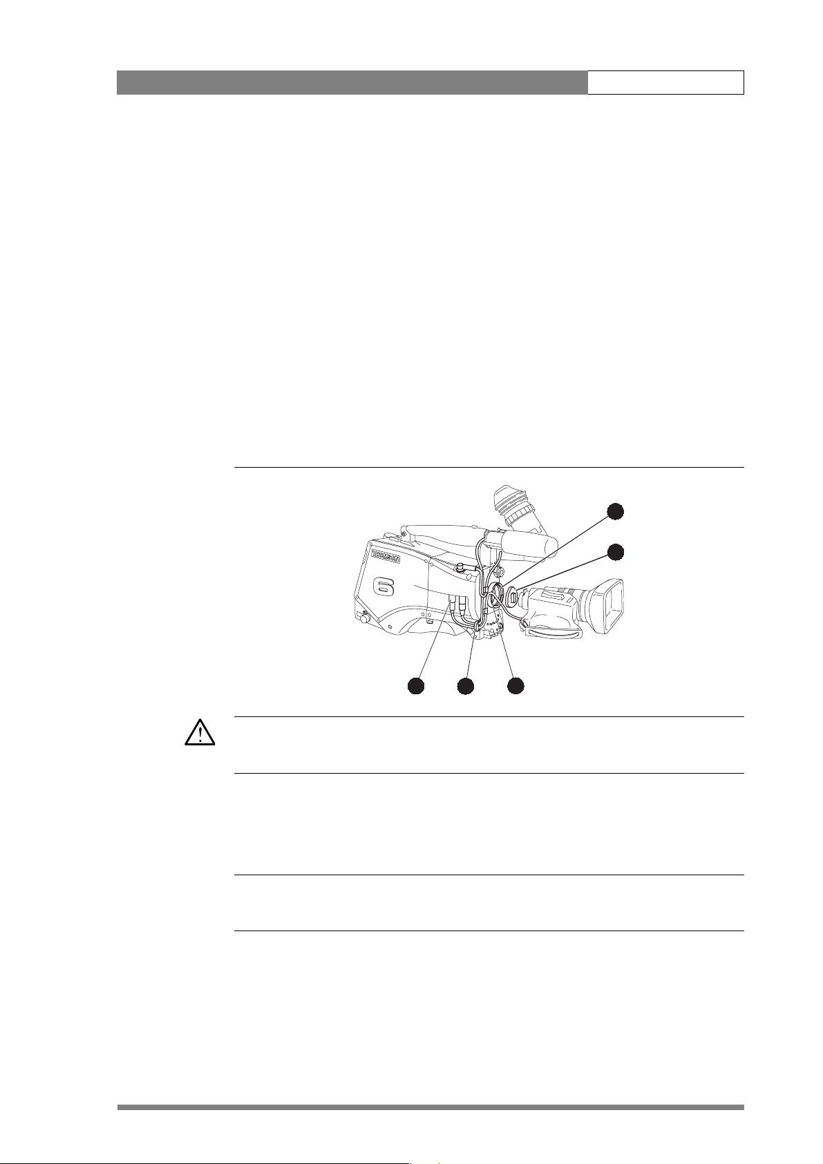
2.4 1.5-inch Viewfinder
2.4.1 Mounting viewfinder and microphone holder
To mount the 1.5-inch viewfinder proceed as follows:
1. Loosen locking ring (1) of viewfinder support bracket (2) at the front of the
camera handle. (As seen from the rear of the camera, turning the locking ring
counterclockwise moves it towards the handle.)
2. Slide the viewfinder onto the viewfinder support bracket.
3. Tighten the locking ring (1) by turning it clockwise (as seen from rear) so that
the viewfinder is mounted securely to the support.
4. Connect the viewfinder cable to the viewfinder connector socket (6) at the top
right of the camera.
5. Slide the microphone holder (4) onto the viewfinder and secure with the
knurled screw (5).
Caution
Always fit the microphone holder as it functions as a safety stop for the viewfinder.
6. To improve the comfort of the skin contact when using the viewfinder, fit the
eye piece cover (3) to the rubber eyepiece. Spare eye piece covers
(3922 405 00461) are available at your Thomson Broadcast and Media
Solutions representative.
Figure 2-3. Viewfinder mounting
3
2
1
6
5
4
Page 18
Installation | 1.5-inch Viewfinder Accessories 2-5
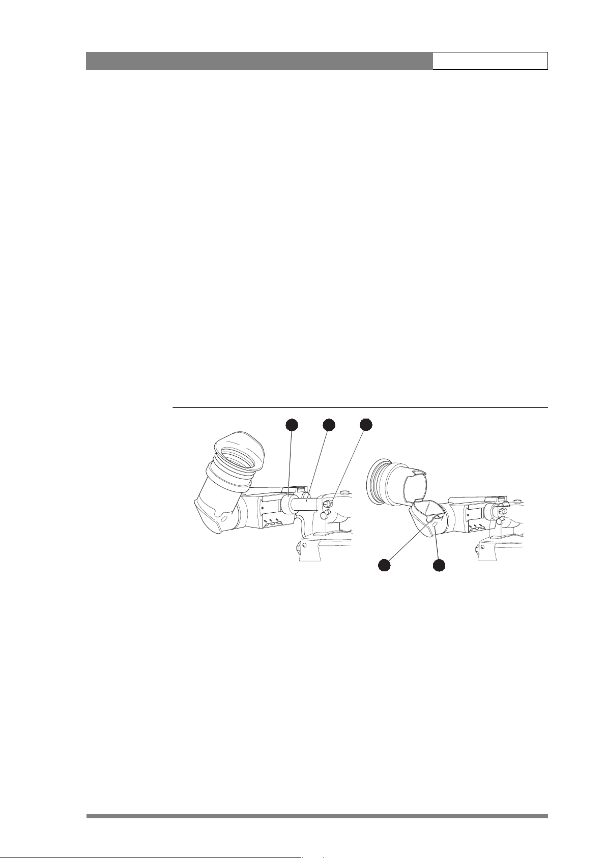
2.4.2 Positioning the viewfinder
The horizontal position of the viewfinder can be adjusted as follows to suit your
requirements:
1. Loosen the locking ring (1). (As seen from the rear of the camera, turning the
locking ring counterclockwise moves it towards the handle.)
2. Slide the viewfinder horizontally along the rail to the desired position.
3. Tighten the locking ring (1) by turning clockwise.
The dioptre hood and eyepiece of the viewfinder can be rotated vertically.
The viewfinder can be positioned backwards and forwards along the camera axis.
Loosen the support bracket round bar retaining lever (2) and slide the round bar (3)
forwards or backwards. When the desired position is reached tighten the support
bracket round bar retaining lever (2) again.
To use the viewfinder at a distance press the button (4) below or above the eyepiece
tube and swing it free of the associated clip (5). The display can now be seen from
further away.
Figure 2-4. Viewfinder positioning
1
3
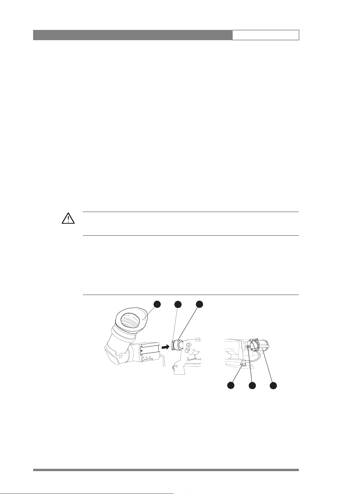
2.5 1.5-inch Viewfinder Accessories
2.5.1 Wide angle eyepiece
If you regularly use the viewfinder at a distance, for example, when you use the camera
in the hand-held position, it is recommended that you fit the optionally available wide
angle eyepiece (LDK 5390/00).
2
5
4
Page 19
Installation | 1.5-inch Viewfinder Accessories 2-6
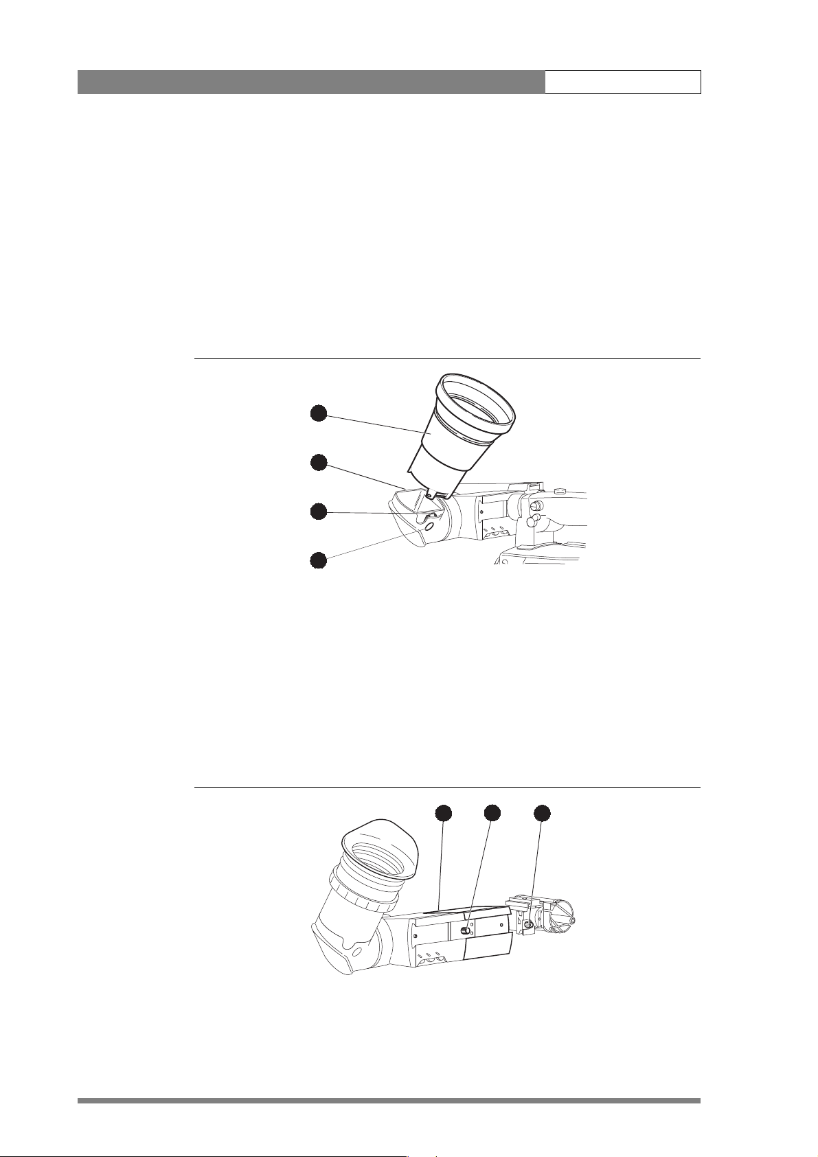
To fit the wide angle eyepiece proceed as follows:
1. Hold the eyepiece (1) securely.
2. Press the button (2) below the eyepiece tube and swing it free of the button
clip (3).
3. Press the button (4) above the eyepiece tube and remove the eyepiece.
4. Fit the wide angle eyepiece (1) to the two clips (3) ensuring that they both click
into place.
Figure 2-5. Viewfinder wide angle eyepiece
1
4
2.5.2 Left eye adapter
A left eye adapter is optionally available (LDK 5390/10) to allow the viewfinder to be
used with the left eye.
Before mounting the viewfinder onto the camera, attach the left eye adapter (1) to the
viewfinder and secure it using the screw (2). Do not forget to mount the microphone
support bracket (3) at the end of the left eye adapter.
Figure 2-6. Viewfinder left eye adapter
3
2
1
2
3
Page 20
Installation | Mounting a microphone 2-7
2.6 Mounting a microphone
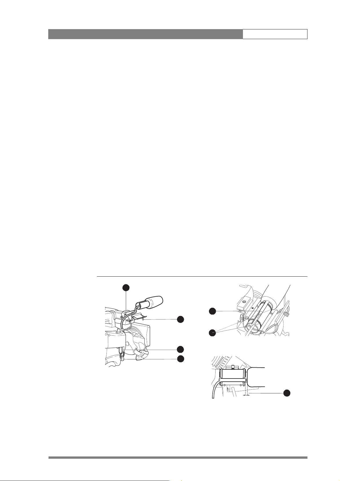
To attach the optional microphone (AJ MC700) to the camera proceed as follows:
1. Open the microphone holder by unscrewing the knurled screw (2) of the
microphone support bracket (1) on the viewfinder and open.
2. Slide the microphone into the split tube until the microphone shoulder reaches
the mark (5) in the tube.
3. Place the tube with the microphone into the holder with the split facing
upwards. Mount the microphone as straight as possible.
4. Ensure that the rubber supports at the back and front of the holder fit into the
rims (6) around the tube.
5. Close the holder and tighten the knurled screw at the top. Don’t allow the
wind hood to touch the holder (7) as this reduces the damping effect.
6. Connect the microphone cable to the MIC audio connector (3) on the right
side of the camera. To avoid mechanical pick-up, do not let the microphone
cable touch the holder.
7. Place the microphone cable into the top clip at the front of the camera and
into clip (4) at the side of the camera. (Pull and twist clip to open it.)
Other microphones with a diameter of 21mm can also be used, however, ensure that
the phantom power and the sensitivity of the input that match that type of
microphone are correctly selected in the camera systems menu. When a longer
microphone is used, it is not necessary to place it in the split tube.
Figure 2-7. Microphone mounting
1
5
2
6
3
4
7
Page 21
Installation | Tripod adapter plate 2-8
2.7 Tripod adapter plate
To mount the camera on a tripod, the tripod plate (LDK 5031/00 is delivered as
standard) must first be attached to the tripod. Follow the tripod manufacturer’s
instructions to mount the wedge plate supplied with the tripod and the tripod adapter
plate firmly onto the tripod. Attach the camera to the tripod adapter plate as follows:
1. Slide the camera horizontally along the tripod adapter plate from back to front
ensuring that the front of the camera engages the V-slot (1) at the front of the
tripod adapter plate, and that the slot on the bottom of the camera engages
the stud (2) at the rear of the tripod adapter plate.
2. Firmly push the camera forward until it clicks into place.
Caution
Failure to attach the camera to the tripod adapter plate in the correct manner could
result in an unsecured camera. Ensure that the rear stud (2) is engaged and that the
camera clicks into place.
Remove the camera from the tripod as follows:
1. Press the red locking lever (3) against release handle (4) on the tripod adapter
plate and hold.
2. Ensure that you have a firm hold of the camera.
3. Pull the release handle (4) forward.
4. Move the camera backwards and up. The camera is now free from the tripod
adapter plate.
Figure 2-8. Tripod adapter plate
r
a
le
C
1
A
r
a
le
C
/4
1
D
N
2
B
P
r 4
ta
S
6
/1
1
3
C
PND
r 6
ta
S
4
/6
1
D
N
4
D
s
u
c
ft fo
o
S
1
3
4
2
5
Page 22
Installation | Adjusting the shoulder pad 2-9
When a 5-inch viewfinder is used with the camera it is recommended that the
optionally available tripod adapter plate LDK 5030 be used. This tripod plate has an
extra locking lever (5) at the rear which provides an additional clamp for the rear stud
and so gives extra stability to the mount. When the camera is mounted on the tripod
tighten this locking lever (5) to ensure that the stud (2) at the rear of the plate is locked
firmly in place. When removing the camera first open the locking lever (5) to free the
rear stud (2).
2.8 Adjusting the shoulder pad
To change the position the shoulder pad press and hold lever (1). The shoulder pad can
now be moved backwards and forwards along the axis of the camera. Adjust the
shoulder pad when all units have been mounted so that the best balanced position can
be obtained.
Figure 2-9. Shoulder pad
1
Page 23
Installation | Mounting a top light 2-10
2.9 Mounting a top light
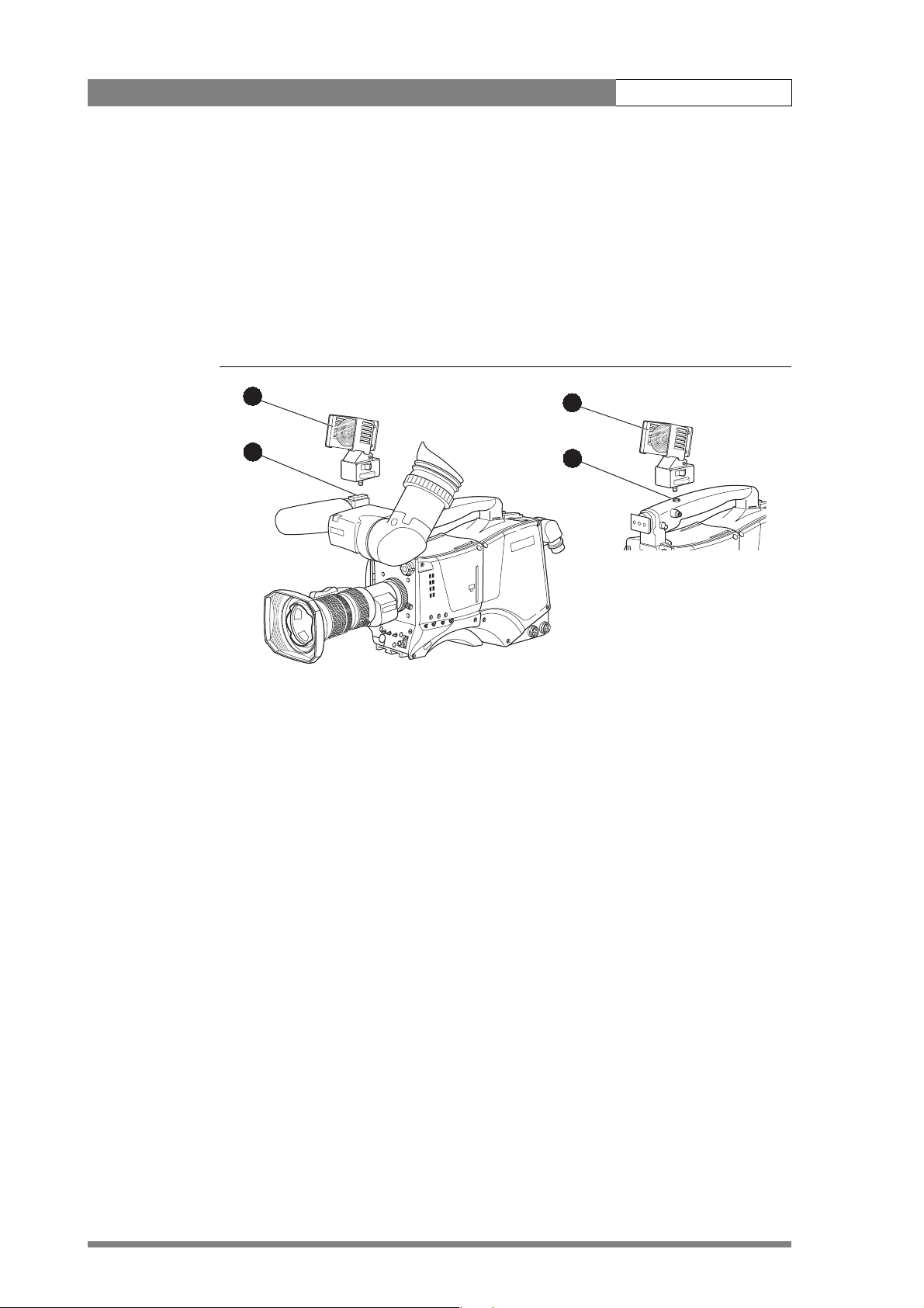
To mount a top light (1) onto the camera, proceed as follows:
1. Screw the top light into either the WW1/4” - 20 screw hole (2) located on the
carrying handle or the screw hole (3) on the top of the microphone holder.
2. Power the top light according to the instructions delivered with the light.
Figure 2-10. Top light
1
2
ar
le
C
1
A
r
lea
C
/4
1
D
N
2
B
r 4P
ta
S
6
/1
1
D
N
3
C
P
r 6
ta
S
4
/6
1
D
4
D
sN
cu
ft fo
o
S
1
3
Page 24
Installation | Zoom controls 2-11
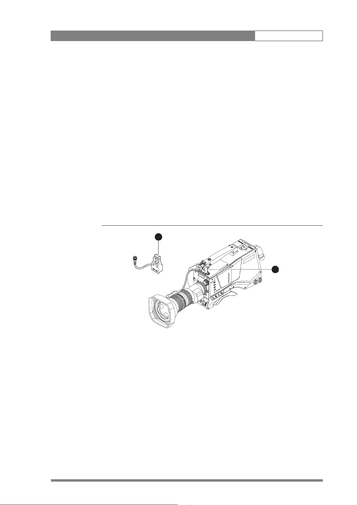
2.10 Zoom controls
The camera has a zoom control on the carrying handle for lenses with a digital
interface. If you wish to control a lens with an analog interface, an optional zoom
control unit (1) can be mounted on the carrying handle instead.
The three available versions for different types of lens are:
• LDK 6113 / 16 for Fujinon.
• LDK 6113 / 26 for Canon.
• LDK 6113 / 36 for Angenieux.
This control unit not only controls the zoom but also has mini-button controls for the
VTR start/stop function and the VTR Ret. function. These are located under the front of
the carrying handle (2).
The instructions for mounting the zoom control unit and the function of the controls
are supplied with the unit.
Figure 2-11. Zoom controls
1
2
lear
C
1
A
r
1/4
Clea
ND
2
B
/16
1
r 4P
ta
ND
S
3
4
C
1/6
D
N
Star 6P
4
D
oft focus
S
Page 25
Installation | Attaching an adapter 2-12
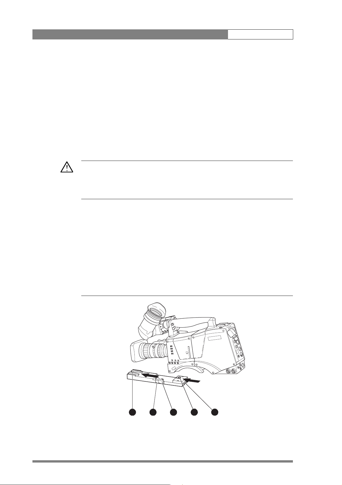
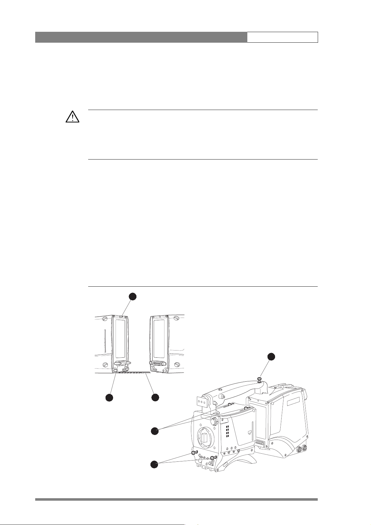
2.11 Attaching an adapter
The LDK 500 camera head is a multi-role camera head that can be used with various
adapters.
Caution
Be extremely careful with the connectors between the camera head and the adapter.
Do not allow the guide pins to damage the pins of the connector. Follow these steps in
the order given. Tightening or loosening the screws in the wrong order could result in
mechanical damage to the camera.
To attach an adapter to the camera proceed as follow:
1. Using the rail (1) on the bottom of the camera head as a guide, fit the guide
pins (2) on either side of the connector and the guide pin (3) at the top rear of
the camera head into the corresponding slots of the adapter.
2. First, tighten the two horizontal screws (4) on the top of camera.
3. Next, tighten the two horizontal screws (5) at the front of the camera.
4. Lastly, tighten the vertical screw (6) in the handle of the camera.
To detach an adapter from the camera head follow the steps for attaching it in the
reverse order.
Figure 2-12. Attaching an adapter
3
6
2
1
Clear
1
A
Clear
ND1/4
B2
4
Star 4P
3
C
Star 6P ND 1/16
4
D
Soft focus ND 1/64
5
Page 26

Cabling and connectors 3-1
Chapter 3
Cabling and connectors
This section describes how to integrate the camera system into your studio system.
Information is also provided on the connectors used in the camera and adapter.
Contents
Configurations . . . . . . . . . . . . . . . . . . . . . . . . . . . . . . . . . . . . . . . . . . . . . . . . . . . 3-2
Camera with Triax adapter . . . . . . . . . . . . . . . . . . . . . . . . . . . . . . . . . . . . . . . . 3-2
Multiple Triax cameras with C2IP network . . . . . . . . . . . . . . . . . . . . . . . . . . . . 3-2
Camera with Triax adapter and SuperXpander . . . . . . . . . . . . . . . . . . . . . . . . . 3-4
Camera connectors . . . . . . . . . . . . . . . . . . . . . . . . . . . . . . . . . . . . . . . . . . . . . . . . 3-5
Viewfinder connector . . . . . . . . . . . . . . . . . . . . . . . . . . . . . . . . . . . . . . . . . . . . 3-5
Lens connector . . . . . . . . . . . . . . . . . . . . . . . . . . . . . . . . . . . . . . . . . . . . . . . . . 3-6
Audio microphone connector . . . . . . . . . . . . . . . . . . . . . . . . . . . . . . . . . . . . . . 3-6
RS232 serial connector . . . . . . . . . . . . . . . . . . . . . . . . . . . . . . . . . . . . . . . . . . . 3-7
Triax adapter connectors . . . . . . . . . . . . . . . . . . . . . . . . . . . . . . . . . . . . . . . . . . . . 3-8
Triax connector. . . . . . . . . . . . . . . . . . . . . . . . . . . . . . . . . . . . . . . . . . . . . . . . . 3-9
CVBS output connector . . . . . . . . . . . . . . . . . . . . . . . . . . . . . . . . . . . . . . . . . . 3-9
Viewfinder / External video output connector . . . . . . . . . . . . . . . . . . . . . . . . . . 3-9
Script light power supply socket . . . . . . . . . . . . . . . . . . . . . . . . . . . . . . . . . . . 3-10
Teleprompter video output connector. . . . . . . . . . . . . . . . . . . . . . . . . . . . . . . 3-10
DC power and tally output socket . . . . . . . . . . . . . . . . . . . . . . . . . . . . . . . . . 3-10
Audio microphone 2 connector . . . . . . . . . . . . . . . . . . . . . . . . . . . . . . . . . . . 3-11
DC power input socket. . . . . . . . . . . . . . . . . . . . . . . . . . . . . . . . . . . . . . . . . . 3-11
Audio microphone 1 connector . . . . . . . . . . . . . . . . . . . . . . . . . . . . . . . . . . . 3-12
Intercom headset connector . . . . . . . . . . . . . . . . . . . . . . . . . . . . . . . . . . . . . . 3-12
Reference input connector . . . . . . . . . . . . . . . . . . . . . . . . . . . . . . . . . . . . . . . 3-13
Tracker communications connector . . . . . . . . . . . . . . . . . . . . . . . . . . . . . . . . 3-13
Auxiliary connector. . . . . . . . . . . . . . . . . . . . . . . . . . . . . . . . . . . . . . . . . . . . . 3-14
Page 27

Cabling and connectors | Configurations 3-2
3.1 Configurations
3.1.1 Camera with Triax adapter
A camera head with an LDK 5430 Triax adapter can be connected to an LDK 4501 Base
Station using a Triax cable. The maximum length of cable that can be used without
significant degradation of the video signal is 3000m (10,000 ft.) for a 14mm Triax
cable. The power supply is applied to the Base Station and via the Triax cable to the
camera. An OCP 400 operational control panel can be connected directly to the Base
Station using a cross-over Ethernet cable.
Figure 3-1. Camera with Triax adapter
Triax adapter
1
A
Clear
Clear
ND1/4
Star 4P
2
B
ND1/16
Star 6P
3
C
Smart
card
ND1/64
Soft Focus
4
D
l
e
w
P
on
Power
TrackerAux
Ethernet cable
Camera head
Base Station
Triax cable
3.1.2 Multiple Triax cameras with C2IP network
Each camera head with an LDK 5430 Triax adapter can be connected to an LDK 4501
Base Station using a Triax cable. The maximum length of cable that can be used
without significant degradation of the video signal is 3000m (10,000 ft.) for a 14mm
Triax cable. The power supply is applied to the Base Station and via the Triax cable to
the camera.
The Base Stations are each connected to a network hub or router via an Ethernet cable
(straight through, not cross-over). The OCP 400 operational control panels and, if
required the MCP 400 Master Control Panel, are also connected to the Ethernet
network via a hub or router.
Optionally, a Series 9000 OCP can be connected directly to a Base Station using a twowire bus cable. In this situation no loop-through is available and the camera number
must be set to 1.
Power supply
THOMSON
Camera Base Station
OCP 400
Page 28
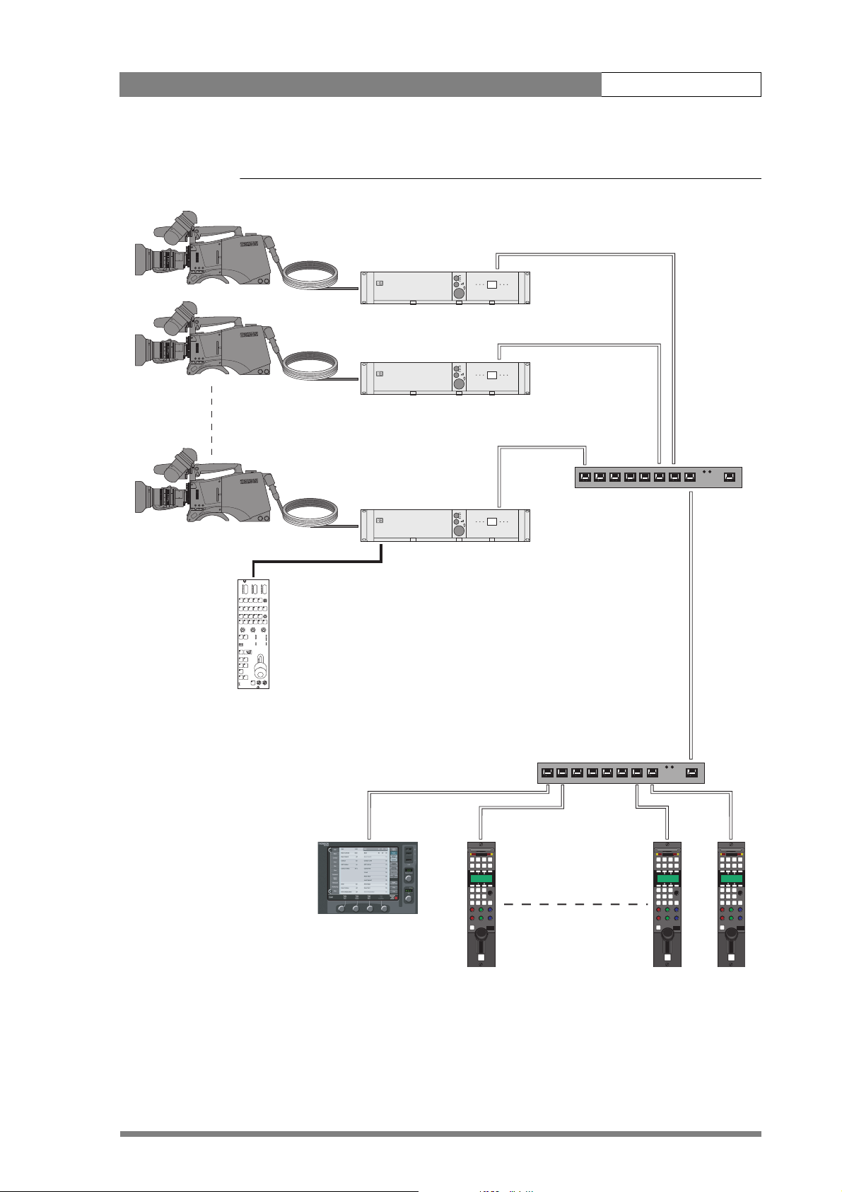
Cabling and connectors | Configurations 3-3
Figure 3-2. Multiple cameras with C2IP network control
Triax adapter
1
A
Clear
Clear
2
B
ND1/4
Star 4P
3
C
ND1/16
Star 6P
Smart
card
4
D
ND1/64
Soft Focus
l
e
w
P
er
ow
on
P
1
A
Clear
Clear
2
ND1/4
B
Star 4P
3
ND1/16
C
Star 6P
Smart
card
4
ND1/64
D
Soft Focus
l
e
w
P
er
ow
on
P
1
A
Clear
Clear
2
B
ND1/4
Star 4P
3
C
ND1/16
Star 6P
Smart
card
4
D
ND1/64
Soft Focus
l
e
w
P
er
on
Pow
Camera head
TrackerAux
TrackerAux
Triax cable
TrackerAux
Base Station
THOMSON
Camera Base Station
THOMSON
Camera Base Station
THOMSON
Camera Base Station
Ethernet cable
Hub or router
Series 9000 OCP
Two-wire bus cable
Hub or router
Ethernet cable
MCP 400
OCP 400
Page 29

Cabling and connectors | Configurations 3-4
3.1.3 Camera with Triax adapter and SuperXpander
A camera head with an LDK 5430 Triax adapter can be mounted in the LDK 4482
SuperXpander. This enables large box lenses to be used with the camera. The Triax
adapter connects to the SuperXpander via a flying lead. A 7-inch viewfinder LDK 4016
is mounted on the SuperXpander. The power supply for the camera is applied to the
SuperXpander.
The SuperXpander is connected to an LDK 4501 Base Station using a Triax cable. The
maximum length of cable that can be used without significant degradation of the
video signal is 3000m (10,000 ft.) for a 14mm Triax cable. The Base Station is powered
by a separate mains power supply. An OCP 400 operational control panel can be
connected directly to the Base Station using a cross-over Ethernet cable.
Figure 3-3. Camera with SuperXpander and Triax adapter
7-inch
Viewfinder
SuperXpander
Triax cable
Triax adapter
Camera head
Base Station
Power supply
Ethernet cable
THOMSON
Camera Base Station
OCP 400
Page 30

Cabling and connectors | Camera connectors 3-5
3.2 Camera connectors
Figure 3-4. Camera connector location
Viewfinder connector
Lens connector
Audio microphone connector RS232 connector
3.2.1 Viewfinder connector
Figure 3-5. Camera viewfinder connector
3 41 2 5
8 96 7 10
13 1411 12 15
18 1916 17 20
bts1009
1. -80V
2. n.c.
3. GND
4. INTN-D
5. vf ext video
6. n.c.
7. vf video ret
8. SDA-D
9. SCL-D
10. vf ext video ret
11. GND
12. vf video
13. Pb vf ret
14. Pr vf ret
15. GND
16. +batt
17. +batt
18. Pb vf
19. Pr vf
20. shield
20-pole female; panel view
Panel part number (X14): 5322 214 12544
Cable part number (male): 5322 320 12159
Page 31

Cabling and connectors | Camera connectors 3-6
3.2.2 Lens connector
Figure 3-6. Camera lens connector
1
9
8
7
10
6
5
2
1112
3
4
Hirose 12-pole female; panel view
Panel part number (X15): 5322 265 10389
Cable part number (male): 5322 265 41208
3.2.3 Audio microphone connector
Figure 3-7. Audio microphone connector
1
3
1. Ext. Video On/Off
2. VTR Trigger Switch
3. -batt
4. Momentary Iris
5. IrisControl
8. Lens Servo
9. Range Extender
10. Zoom Follow
11. TXD
12. RXD
6. + batt
7. Iris Follow
1. Audio Screen
2. Audio In
3. Audio Return
Microphone impedance >200 ohm
Sensitivity range: -70 to -28 dBm
2
XLR 3-pole female; panel view
Panel part number (X13): 5322 267 40523
Signal at pin 2 of audio input is in phase with signal at pin
2 of audio output.
Page 32

Cabling and connectors | Camera connectors 3-7
3.2.4 RS232 serial connector
Figure 3-8. RS232 serial connector
54321
876
9
SubD 9-pin male; panel view (X12)
1. SPARE
2. RS-RXD
3. RS-TXD
4. RS-DTR
5. RS-DGND
6. RS-DSR
7. RS-RTS
8. RS-CTS
9. +12V
Page 33
Cabling and connectors | Triax adapter connectors 3-8
3.3 Triax adapter connectors
Figure 3-9. Triax adapter connector location
Triax connector
Eng
Front
Off
Prod
Rear
Loc
Ext
Mix
Eng Progr Prod
Intercom headset
CVBS output
CVBS (option)
Call
Viewfinder/Ext. video output
Script light power supply
Teleprompter output
DC power and tally output
REF
IN
Ext 1
Ext 2
12V 1.5A DC Out
Script
Light
Breaker
Power on
TP
VF
Front Rear 48V
Mic
Ext
Audio microphone 1
input
DC power supply
DC in
48VOn
input
Audio microphone 2
Mic 2
input
Tracker
Aux
Reference signal input
Auxiliary
connector
Tracker
communication
connector
Page 34

Cabling and connectors | Triax adapter connectors 3-9
3.3.1 Triax connector
Figure 3-10. Triax connector
1. Centre pin: Power and signals
2. Inner shield: Return
3. Outer shield: Camera housing GND
Centre pinOuter shield Inner shield
Panel view (X100)
3.3.2 CVBS output connector
Figure 3-11. CVBS output connector
This socket provides a 1.0 Vpp CVBS output video signal if
the optional encoder board is fitted.
BNC connector: panel view (X105)
3.3.3 Viewfinder / External video output connector
Figure 3-12. Viewfinder / External video output connector
This socket provides a 1.0 Vpp VBS output viewfinder
signal or the external video signal from the Base Station.
NC connector: panel view (X106)
Page 35

Cabling and connectors | Triax adapter connectors 3-10
3.3.4 Script light power supply socket
Figure 3-13. Script light power supply output connector
1. +12 Vdc (maximum dissipation 3W)
2. Power return
3. Shield
1
2
3
Fischer 3-pole female: panel view (X102)
3.3.5 Teleprompter video output connector
Figure 3-14. Teleprompter video output connector
BNC connector: panel view (X112)
3.3.6 DC power and tally output socket
Figure 3-15. DC power and tally output connector
1
4
2
3
This socket supplies the 1Vpp teleprompter signal applied
to the Base Station. (This socket has no output if the
reference input socket is used as a return video channel).
1. Ground
2. On air
3. No connection
4. +12 Vdc (max. 18W)
Shield of cable directly to the connector housing.
The socket provides access to an internal tally switch.
When the camera is on-air, the contact of the internal
relay is closed.
Hirose 4-pole female: panel view (X110)
Page 36

Cabling and connectors | Triax adapter connectors 3-11
3.3.7 Audio microphone 2 connector
Figure 3-16. Audio microphone 2 connector
1. Audio Screen
2. Audio In
1
3
3. Audio Return
Microphone impedance >200 ohm
Sensitivity range: -64 to -24 dBu
2
XLR 3-pole female; panel view (X107)
3.3.8 DC power input socket
Caution
The input voltage must not exceed +17 Vdc.
Figure 3-17. DC power input connector
1
23
Signal at pin 2 of audio input is in phase with signal at pin
2 of audio output.
1. Ground
2. No connection
3. No connection
4. +10.5 Vdc . . . +17 Vdc
4
This socket accepts a DC voltage of 12V nominal.
Maximum power consumption 23W.
XLR 4-pin male: panel view (X101)
Page 37

Cabling and connectors | Triax adapter connectors 3-12
3.3.9 Audio microphone 1 connector
Figure 3-18. Audio microphone 1 connector
1. Audio Screen
2. Audio In
1
3
3. Audio Return
Microphone impedance >200 ohm
Sensitivity range: -64 to -24 dBu
2
XLR 3-pole female; panel view (X107)
3.3.10 Intercom headset connector
Figure 3-19. XLR intercom headset connector
1
2
3
4
5
XLR 5-pole female; panel view (X104)
Signal at pin 2 of audio input is in phase with signal at pin
2 of audio output.
1. Microphone return
2. Microphone
3. Telephone return
4. Telephone left
5. Telephone right
Microphone level: -64 dBu / -24 dBu switchable
Microphone impedance: >600 Ohm
Telephone level: +6 dBu nominal
Telephone output impedance: <50 Ohm
Figure 3-20. Tuchel intercom headset connector
1. Telephone left
2. Not connected
1
2
3
6
5
4
Tuchel 6-pole female; panel view (X104)
3. Microphone
4. Microphone return
5. Telephone right
6. Telephone return
Microphone level: -64 dBu / -24 dBu switchable
Microphone impedance: >600 Ohm
Telephone level: +6 dBu nominal
Telephone output impedance: <50 Ohm
Page 38

Cabling and connectors | Triax adapter connectors 3-13
3.3.11 Reference input connector
Figure 3-21. Reference input connector
This conector is used to supply a 1 Vpp reference signal to
the camera for genlocking when the optional encoder is
fitted.
This connector can be used as an input socket for a 1 Vpp
CVBS signal which is output on the TP out connector of
the Base Station. This is only possible with Base Station
LDK 4501 and when the optional encoder is fitted. Select
the function of this socket in the camera Install menu or
the Base Station System menu.
BNC connector: panel view (X111)
3.3.12 Tracker communications connector
Figure 3-22. Tracker communications connector
1. On-air signal return
2. Tracker microphone return
10
9
11
23
8
1
4
5
7
6
ischer 11-pole female; panel view
anel part number (X108): 3922 040 02463
3. Tracker microphone input
4. Production tracker
5. Sidetone/engineering tracker
6. Intercom return
7. Program sound tracker
8. Cameraman microphone
9. Tally control tracker (Cmos level, R out = 1k)
10. +12V; I max. = 100mA
11. +12V return
Microphone level: -58dBu/-20dBu switchable
Microphone impedance: 200 ohm
Telephone level: + 6dBu
Telephone output impedance: <10 ohm
Page 39

Cabling and connectors | Triax adapter connectors 3-14
3.3.13 Auxiliary connector
Figure 3-23. Auxiliary connector
1. +5VL
2. 0VL
10
9
11
23
8
1
4
5
7
6
3. AN0
4. AN1
5. Spare
6. On-air n.c.
7. Private Data Camera - Base Station
8. Ground
9. Private Data Base Station - Camera
10. Ground
11. Shield
Private data input signals: 0 <0.8 Volt; 1 >2.4 Volt
max. level: +/-12 Volt
input impedance: >100 kOhm
baud rate: 2400 bits/s nom; 4800 bits/s max.
Fischer 11-pole female; panel view
Panel part number (X109): 3922 040 02512
Private data output signals: C-MOS levels 5V
output impedance: <1 kOhm.
Analogue outputs (AN0 and AN1) output level: 0 - 5 Volt
output impedance: 100 Ohm
Page 40

Operating instructions 4-1
Chapter 4
Operating instructions
This section shows the physical location of the controls on the camera. A description is
given of how to navigate through the menu system and set-up your preferences.
Contents
Camera head controls . . . . . . . . . . . . . . . . . . . . . . . . . . . . . . . . . . . . . . . . . . . . . . 4-3
Viewfinder controls . . . . . . . . . . . . . . . . . . . . . . . . . . . . . . . . . . . . . . . . . . . . . . . . 4-4
Assigning functions to buttons . . . . . . . . . . . . . . . . . . . . . . . . . . . . . . . . . . . . . 4-5
Using the camera. . . . . . . . . . . . . . . . . . . . . . . . . . . . . . . . . . . . . . . . . . . . . . . . . . 4-6
Switching on the power . . . . . . . . . . . . . . . . . . . . . . . . . . . . . . . . . . . . . . . . . . 4-6
Controlling the camera. . . . . . . . . . . . . . . . . . . . . . . . . . . . . . . . . . . . . . . . . . . 4-6
Access and Security . . . . . . . . . . . . . . . . . . . . . . . . . . . . . . . . . . . . . . . . . . . . . . . . 4-7
Camera cards . . . . . . . . . . . . . . . . . . . . . . . . . . . . . . . . . . . . . . . . . . . . . . . . . . 4-7
Access control . . . . . . . . . . . . . . . . . . . . . . . . . . . . . . . . . . . . . . . . . . . . . . . . . 4-8
Camera card slot . . . . . . . . . . . . . . . . . . . . . . . . . . . . . . . . . . . . . . . . . . . . . . . 4-8
System Menu. . . . . . . . . . . . . . . . . . . . . . . . . . . . . . . . . . . . . . . . . . . . . . . . . . . . . 4-9
Entering the System menu . . . . . . . . . . . . . . . . . . . . . . . . . . . . . . . . . . . . . . . . 4-9
Finding your way . . . . . . . . . . . . . . . . . . . . . . . . . . . . . . . . . . . . . . . . . . . . . . 4-10
Leaving the System Menu. . . . . . . . . . . . . . . . . . . . . . . . . . . . . . . . . . . . . . . . 4-10
Making changes . . . . . . . . . . . . . . . . . . . . . . . . . . . . . . . . . . . . . . . . . . . . . . . 4-11
Undoing changes . . . . . . . . . . . . . . . . . . . . . . . . . . . . . . . . . . . . . . . . . . . . . . 4-11
Viewfinder preferences . . . . . . . . . . . . . . . . . . . . . . . . . . . . . . . . . . . . . . . . . . . . 4-12
Viewfinder picture quality. . . . . . . . . . . . . . . . . . . . . . . . . . . . . . . . . . . . . . . . 4-12
Video level indication . . . . . . . . . . . . . . . . . . . . . . . . . . . . . . . . . . . . . . . . . . . 4-12
Tally indicators . . . . . . . . . . . . . . . . . . . . . . . . . . . . . . . . . . . . . . . . . . . . . . . . 4-12
Viewfinder markers . . . . . . . . . . . . . . . . . . . . . . . . . . . . . . . . . . . . . . . . . . . . 4-12
Lens preferences . . . . . . . . . . . . . . . . . . . . . . . . . . . . . . . . . . . . . . . . . . . . . . . . . 4-13
Lens type . . . . . . . . . . . . . . . . . . . . . . . . . . . . . . . . . . . . . . . . . . . . . . . . . . . . 4-13
Auto iris . . . . . . . . . . . . . . . . . . . . . . . . . . . . . . . . . . . . . . . . . . . . . . . . . . . . . 4-13
Extended Iris. . . . . . . . . . . . . . . . . . . . . . . . . . . . . . . . . . . . . . . . . . . . . . . . . . 4-13
Lens indicators . . . . . . . . . . . . . . . . . . . . . . . . . . . . . . . . . . . . . . . . . . . . . . . . 4-13
Video preferences . . . . . . . . . . . . . . . . . . . . . . . . . . . . . . . . . . . . . . . . . . . . . . . . 4-14
Standard settings . . . . . . . . . . . . . . . . . . . . . . . . . . . . . . . . . . . . . . . . . . . . . . 4-14
Test signal . . . . . . . . . . . . . . . . . . . . . . . . . . . . . . . . . . . . . . . . . . . . . . . . . . . 4-14
Gain selection. . . . . . . . . . . . . . . . . . . . . . . . . . . . . . . . . . . . . . . . . . . . . . . . . 4-15
Optical filter selection . . . . . . . . . . . . . . . . . . . . . . . . . . . . . . . . . . . . . . . . . . . 4-15
Colour temperature selection . . . . . . . . . . . . . . . . . . . . . . . . . . . . . . . . . . . . . 4-16
Exposure time. . . . . . . . . . . . . . . . . . . . . . . . . . . . . . . . . . . . . . . . . . . . . . . . . 4-18
Black stretch. . . . . . . . . . . . . . . . . . . . . . . . . . . . . . . . . . . . . . . . . . . . . . . . . . 4-21
Auto skin contour. . . . . . . . . . . . . . . . . . . . . . . . . . . . . . . . . . . . . . . . . . . . . . 4-21
Classic mode . . . . . . . . . . . . . . . . . . . . . . . . . . . . . . . . . . . . . . . . . . . . . . . . . 4-22
Page 41

Operating instructions | 4-2
Managing files. . . . . . . . . . . . . . . . . . . . . . . . . . . . . . . . . . . . . . . . . . . . . . . . . . . 4-22
Scene files . . . . . . . . . . . . . . . . . . . . . . . . . . . . . . . . . . . . . . . . . . . . . . . . . . . 4-22
Operator files . . . . . . . . . . . . . . . . . . . . . . . . . . . . . . . . . . . . . . . . . . . . . . . . . 4-23
Standard files . . . . . . . . . . . . . . . . . . . . . . . . . . . . . . . . . . . . . . . . . . . . . . . . . 4-23
Customer standard files . . . . . . . . . . . . . . . . . . . . . . . . . . . . . . . . . . . . . . . . . 4-23
User levels . . . . . . . . . . . . . . . . . . . . . . . . . . . . . . . . . . . . . . . . . . . . . . . . . . . . . . 4-23
Selecting the user level . . . . . . . . . . . . . . . . . . . . . . . . . . . . . . . . . . . . . . . . . . 4-24
Smart-Touch™ . . . . . . . . . . . . . . . . . . . . . . . . . . . . . . . . . . . . . . . . . . . . . . . . . . 4-24
Triax adapter controls . . . . . . . . . . . . . . . . . . . . . . . . . . . . . . . . . . . . . . . . . . . . . 4-26
Powering the camera . . . . . . . . . . . . . . . . . . . . . . . . . . . . . . . . . . . . . . . . . . . 4-27
Selecting monitoring signals . . . . . . . . . . . . . . . . . . . . . . . . . . . . . . . . . . . . . . 4-27
Using audio . . . . . . . . . . . . . . . . . . . . . . . . . . . . . . . . . . . . . . . . . . . . . . . . . . 4-27
Intercom. . . . . . . . . . . . . . . . . . . . . . . . . . . . . . . . . . . . . . . . . . . . . . . . . . . . . 4-28
Communication . . . . . . . . . . . . . . . . . . . . . . . . . . . . . . . . . . . . . . . . . . . . . . . 4-29
Page 42

Operating instructions | Camera head controls 4-3
4.1 Camera head controls
Figure 4-1. Camera head controls
Clear
1
A
Clear
D 1/4
N
2
B
Star 4P
ND 1/16
3
C
Star 4P
4
/6
1
D
N
4
D
t
c
ffe
E
td.
S
ile
F
2
W
S
1
W
S
S
ta
rt
V
s
E
h
x
ift
p
.
T
im
W
h
e
ite
C
B
le
a
l
a
n
s
c
a
n
N
o
m
. le
v
e
l
Power
off
on
Power
t
r
a
m
S
d
r
a
C
Tracker
Aux
1
2
3
4
5
6
7
8
19
9
18
14 13 12151617
1. Filter wheel switches
2. Filter wheel indicators
3. Camera card slot
4. SW1 (assignable button 1)
5. SW2 (assignable button 2)
6. Standard scene file button (Std.)
7. Black stretch switch
8. Colour temp. switch (White bal.)
9. Colour bars switch (Bars)
11
11. Power On/Off switch
12. Menu rotary control
13. Menu select switch
14. Clean Scan button
15. White balance switch
16. Exposure time switch
17. Volume control (Audio Level)
18. Vertical shift switch (V-Shift)
19. VTR Start (assignable button 3)
10
10. Gain selection switch
The digital zoom control on the front of the carrying handle varies the zoom on digital lenses only. There
are mini-button controls for the VTR start/stop and VTR Ret. functions located under the front of the
carrying handle.
Page 43

Operating instructions | Viewfinder controls 4-4
4.2 Viewfinder controls
Figure 4-2. Camera head controls
20
21
26
22
27
23
25
24
28 29
38
37
36
35
20. Tally switch
21. Zebra switch
22. Option (assignable switch 4)
23. Brightness control
24. Contrast control
25. Crispening control
-
++
+
BATT
ND/RE
TAPE
REC
30
31
32
FL
7.55.63.2
AW2AW1
!
33
34
30. Iris indication
31. Zebra pattern
32. Safe area marker
33. Non-standard indicator
34. Colour temperature indicators
35. Message box
26. Dioptre
27. Tally indicators (red)
28. Gain indicators
29. Top indicators
36. Centre marker
37. Cadre marker
38. Zoom indication
Page 44

Operating instructions | Viewfinder controls 4-5
4.2.1 Assigning functions to buttons
The camera head has three assignable buttons, two on the side panel (4) and (5), and
one on the lower front panel (19). The viewfinder has an assignable switch (22). These
buttons can be assigned the following functions:
Table 4-1. Button Assignments
Switch Assignment
SW1 (4) VTR Save
Switch on external signal 1
Switch on external signal 2
SW2 (5) Extended Iris
Switch on external signal 1
Switch on external signal 2
VTR Start (19) VTR Start/Stop
Switch on external signal 2
Intercom
Option (22 on VF) None
Disable camera
The function and behaviour (momentary or alternating) of these buttons are set in the
INSTALL/BUTTONS menu.
Page 45

Operating instructions | Using the camera 4-6
4.3 Using the camera
Attach lens, viewfinder, microphone and any other accessories to the camera. Attach
the triax cable or supply the adapter with power.
4.3.1 Switching on the power
Triax adapter
1. On the Base Station set the master power switch to the ON position. The green
power light lights.
2. Set the Power switch (11) of the camera to the ON position.
☞
Note
The BATT indicator in the viewfinder lights if the camera supply voltage is less than
11V.
3. Allow a few moments for the camera to perform a self-test and for the system
to establish communications.
4.3.2 Controlling the camera
There are several ways of controlling the camera:
• Using an OCP connected to the Base Station.
• Using the switches on the camera itself.
• Using the menu system to select functions.
The following paragraphs describe using the switches on the camera and the menu
system.
Page 46
Operating instructions | Access and Security 4-7
4.4 Access and Security
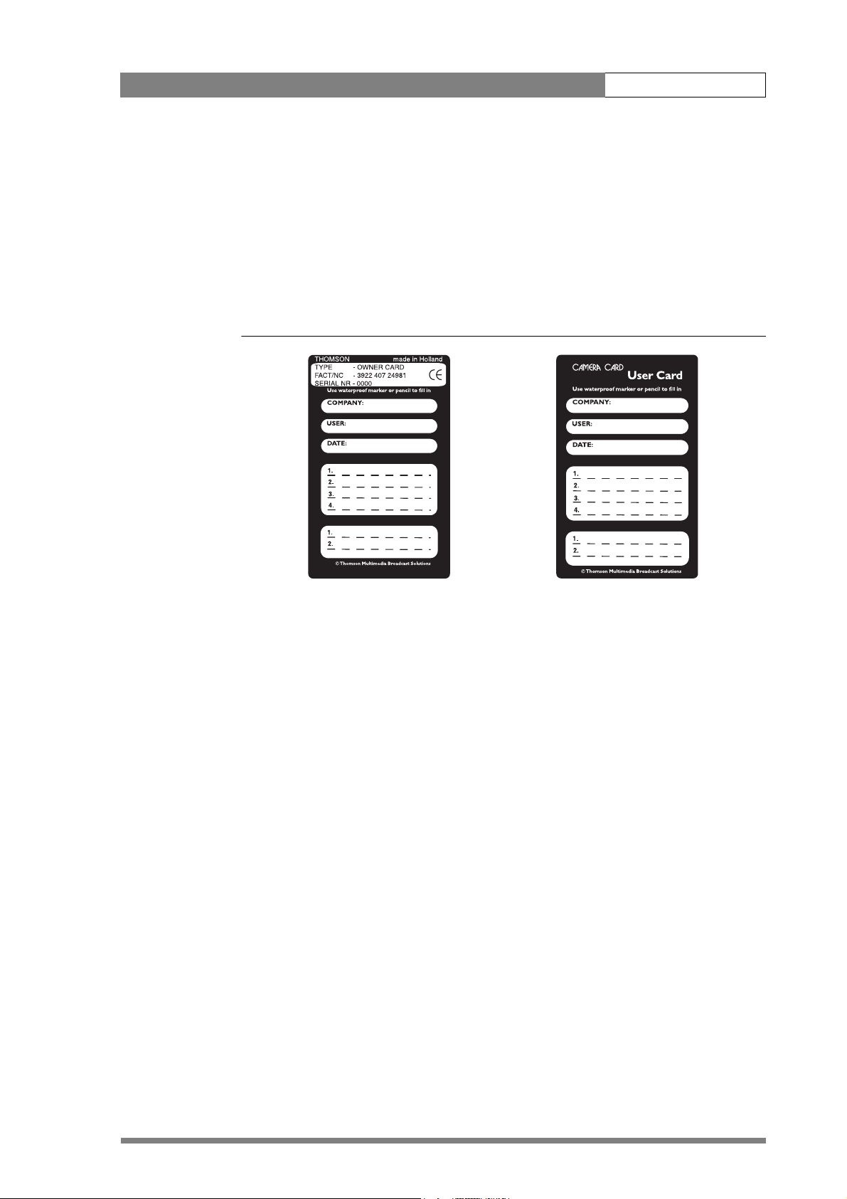
4.4.1 Camera cards
Three camera cards are delivered with each camera. These comprise of two user's cards
and one owner's card.
Figure 4-3. Camera cards
Owner's Card User's Card
The owner's card has three functions:
• As an access control device to the security settings of the camera.
• As a storage device for four scene files.
• As a storage device for two operator files.
The owner's card is unique to every camera. Owner's card and camera must have the
same serial number. An ownerís card is linked to the serial number of the camera and
cannot be used as an ownerís card for another camera.
The user's card has two functions:
• As a storage device for four scene files.
• As a storage device for two operator files.
Scene files
Both the user's card and the owner's card allow four different scene files to be stored
on the card. The recall and storage of a scene file is carried out via the Files menu of
the menu system. A scene file contains information relating to the video settings.
Page 47
Operating instructions | Access and Security 4-8
Operator files
Both the user's card and the owner's card allow two different operator files to be
stored on the card. The recall and storage of a operator file is carried out via the Files
menu of the menu system. An operator file contains information relating to the set-up
of general camera preferences.
4.4.2 Access control
The owner’s card or the PIN code is used to access special set-up and security features
of the camera. Inserting the owner’s card into the camera gives direct access to the
Security menu. If you select the Security menu without this card inserted, you must
enter the correct PIN code to gain access to this menu.
PIN code
The PIN code of the camera can be viewed and changed in the Security menu. The
camera's PIN code when it leaves the factory is set to 0000. It is strongly advised that
this code be changed by the owner on receipt of the camera. This ensures added
protection against unaurthorised access to the Security menu.
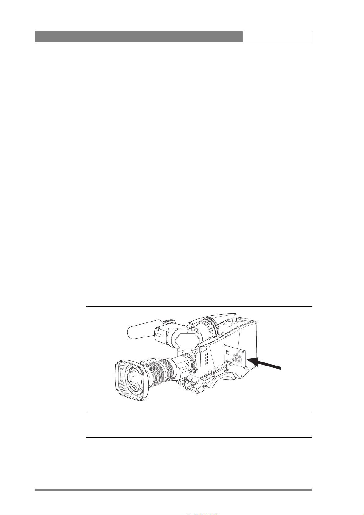
4.4.3 Camera card slot
Insert your camera card into this slot with the chip on the card facing the front of the
camera. Push the card home until it fits snugly. A camera card is not required for
normal operation of the camera.
Figure 4-4. Camera card slot
☞
Note
Only use an original camera card. Store the owner’s card in a safe place.
CAMERA CARD
Page 48

Operating instructions | System Menu 4-9
4.5 System Menu
The camera is operated via the viewfinder text display and the control system menu
switches. The systems menu is viewed in the viewfinder and navigated by means of the
Rotary control (12) and the Select button (13) which are both located at the front of
the camera.
The functions of the camera are grouped into menus and sub-menus. There are eight
different menus that are listed in the main menu as follows:
VF >>
Lens >>
Video >>
Install >>
Files >>
Security >>
Diagnostics >>
Each of these menus gives you access to a particular group of functions. Spend some
time using the controls and menus to discover the various functions. You will quickly
learn to operate the camera intuitively .
☞
Note
Some of the menu items may not appear if the user level is not set to 3.
4.5.1 Entering the System menu
Press the Select button (13) after the camera is switched on, the message Menu off
appears in the viewfinder. Press the Select button again while this text is showing, the
MAIN menu appears in the viewfinder.
Figure 4-5. Main menu
Menu off exec
VF
Lens
Video
Install
MENU: MAIN
Files
Security
Diagnostics
Service
Page 49

Operating instructions | System Menu 4-10
The MAIN menu screen shows five items. The name of the menu is shown below these.
Four more items are hidden but become visible when you scroll down using the Rotary
control (12). A cursor shows your position in the menu. The Rotary control moves
the cursor up and down.
4.5.2 Finding your way
Use the Rotary control (12) to move the cursor through the menu items. If a double
arrow (>>) is visible, then pressing the Select button (13) brings you one level lower in
the menu system. Only five items are visible in each menu. Scroll up or down to see any
additional items. When you first enter a menu (other than the MAIN menu) the cursor
is positioned next to the first item.
The TOP and PREVIOUS entries are not immediately visible but are located above the
first item. Use the Rotary control to scroll up to them.
• Select TOP to bring you back to the MAIN menu.
• Select PREVIOUS to go back to the menu that you were in before the current
one.
The LENS menu, for example, shows the items displayed when you first enter the
menu. The other items are available by scrolling up or down with the Rotary control.
Figure 4-6. Lens menu
4.5.3 Leaving the System Menu
If you are deep within the menu structure, the recommended way of leaving the
System menu is:
TOP
PREVIOUS
Lens type Std
Auto Iris On
Peak/Average 65
Auto iris setp. 35
Mom. iris setp. 50
MENU: LENS
Extended Iris
1. If necessary move the cursor to the left column with the Select button (13).
2. Scroll upwards with the Rotary control (12) until the cursor points to TOP (this
is the MAIN menu).
3. Press the Select button. The cursor now points to the MENU OFF item of the
MAIN menu.
4. Press the Select button to leave the System menu.
Page 50

Operating instructions | System Menu 4-11
If you do not use the menu it disappears after a few seconds. (This delay can be
programmed in the VF menu.) However, when you press the Select button again you
enter the System menu at the last position of the cursor and not at the top of MAIN
menu. To prevent confusion the next time you enter the System menu, it is advisable to
leave the menu by returning to the MAIN menu (TOP) and selecting MENU OFF.
4.5.4 Making changes
To find out where you have to go to change a function, consult the appendix to
discover under which menu group or sub-group the function you want to change is
located. If the cursor points to an item (and there are no double arrows to indicate a
sub-menu) then the item pointed to has a value. The value can be:
• a toggle value (only two values)
• a list value (more than two values)
• an analogue value (variable from 00 to 99)
• unavailable (---).
If the value is unavailable it cannot be changed. This is indicated by three dashes (---).
This can occur, for example, when a function is switched off. The analogue values
associated with that function are then unavailable.
If there are only two values associated with the function, then pressing the Select
button (13) toggles between these two values. If a value is displayed next to a
function that is one of several possible values, then pressing the Select button places
the cursor in a list menu indicating the value currently selected. Use the Rotary
control (12) to point to a new value. Press the Select button to return the cursor to
the function list.
If an analogue value is displayed next to a function name, then pressing the Select
button places the cursor in front of the value and the Rotary control is used to
change the analogue value. Press the Select button to return the cursor to the
function list.
4.5.5 Undoing changes
If you make changes to the video settings in the Systems menu and you decide not to
keep them, use the Std. button (6) at the side of the camera to recall a standard set of
values for the video parameters.
Page 51

Operating instructions | Viewfinder preferences 4-12
4.6 Viewfinder preferences
Set up the viewfinder according to your own preferences; adjust viewing parameters,
select markers, message boxes and on-screen display times.
4.6.1 Viewfinder picture quality
Adjust the Brightness (23) and Contrast (24) controls according to your preferences.
If you wish, use the Crispening (peaking) control (25) to adjust the sharpness of the
viewfinder picture (reduce the crispening when the gain is set to +++).
The dioptre of the viewfinder can be adjusted to suit your eyesight by turning the
Dioptre ring (26). The range of the dioptre is +1 to -3.
4.6.2 Video level indication
Switch on the zebra function so that you are alerted in the viewfinder by a Zebra
pattern (31) in areas where high video levels occur. This diagonal line pattern warns
you that the area affected has risen above a predetermined level of the full scale video
exposure value. Go to the VF menu to set the video levels at which the zebra function
works.
4.6.3 Tally indicators
The red Tally indicators (27) at the front of the viewfinder and at the rear of the
carrying handle light to indicate that the camera is on-air.
The Tally switch (20) is used to control the Tally indicator at the front of the viewfinder.
When this switch is set to the OFF position, the Tally indicator does not light when
the camera is on-air. The Tally switch does not control the tally indicator at the rear of
the carrying handle.
When the camera is on-air, the REC indicator (29) in the viewfinder lights. When the
studio ISO signal is received, the TAPE indicator (29) lights.
4.6.4 Viewfinder markers
Go to the VF menu to select the markers you wish to see in the viewfinder. The
following markers can be set up:
•The Safe area marker (32) indicates an area that represents 80% of the whole
viewfinder picture area. This is the minimum area seen on a TV-set.
•The Message box (35) displays information messages.The length of time this
box remains on the screen is set by the Info time item of the VF menu.
•The Centre marker cross (36) marks the centre of the picture.
•The Cadre marker (37) is a dotted white line or a shaded area that shows the
limits of a 16:9 area in a 4:3 picture, or the limits of a 4:3 area in a 16:9 picture.
Page 52

Operating instructions | Lens preferences 4-13
The Overscan item of the VF menu allows you to see the full captured sensor signal in
the viewfinder when the output signal is 16:11, 16:10 or 16:9. The blanking bars can
be set to either transparent gray or black.
4.7 Lens preferences
When you fit a lens to the camera you may need to adjust the back focus. Refer to the
lens manufacturer's instructions to find out how to do this. The LENS menu allows
you to choose and, if necessary, adjust parameters to suit your lens type and your
personal preferences.
4.7.1 Lens type
In the LENS menu select the lens type from two predefined settings; standard (Std) or
wide angle (WA). This gives you the optimum shading settings for either a standard or
wide angle lens. The lens manufacturer is also selected in this menu.
4.7.2 Auto iris
If required switch on the auto iris function in the LENS menu. You can also select the
parameters associated with the auto and the momentary iris in this menu.
4.7.3 Extended Iris
The extended iris function automatically regulates the video signal level by adjusting
the iris opening, the gain level and the exposure time to suit the ambient lighting
conditions.
To switch on the extended iris function use the Extended iris button (5) at the left-
front side of the camera. When this button is pressed once, the current value of the
automatic extended iris function is displayed. Press the button twice in quick
succession to switch between on and off.
When extended iris is on, the Non-standard indicator (33) in the viewfinder lights,
and gain and exposure controls are blocked. The parameters for the extended iris
function are set in the LENS menu.
4.7.4 Lens indicators
The ND/RE indicator (29) in the viewfinder lights when a lens range extender is
selected.
The Iris indication (30) in the viewfinder shows the value of the iris opening (when
enabled in the VF menu).
The Zoom indicator (38) in the viewfinder shows the degree to which the lens has
been zoomed in or out if this feature is supported by the lens. It shows 50 if not
supported.
Page 53

Operating instructions | Video preferences 4-14
4.8 Video preferences
The means used to control the camera depends on your work methods. A remote OCP
can be used and a low user level can be selected to restrict the available camera
functions. Alternatively, video functions can be controlled on the camera itself. The
following functions are available on the camera:
• Standard settings
•Test signal
• Gain selection
• Optical filter selection
• Colour temperature
• Auto-white balance
• Exposure time
•Black stretch
• Auto skin contour
Many other video functions such as contour, black, gain, knee, gamma, matrix and
white limit functions are available in the VIDEO menu.
4.8.1 Standard settings
To ensure that some of the camera functions are not set to unusual values, a standard
file has been defined that contains the default values for most video functions. The
table in the Appendix lists the values that are set when the standard file is recalled.
To recall the standard values for the various video functions, press the green STD
button (6) on the left-front side of the camera and hold it for two seconds. The
standard values only take effect when the camera is not on-air.
The standard file can be selected as either a factory or a customer standard file.
Changing the standard file can only be done in the System security menu if the owner
card or the PIN code is used.
The Non-standard indicator (33) lights when the video settings are not set to their
standard value, for example, when exposure is not set to nominal. It also lights when
black stretch or extended iris is on and if AWC or FL is selected with the colour
temperature selector.
4.8.2 Test signal
The left-front side panel of the camera has a Colour bar switch (9) for switching on a
colour bar test signal. The colour bar is the standard test signal that is used to set up
and check the camera before use.
Page 54

Operating instructions | Video preferences 4-15
When the colour bar is selected the following functions are temporarily set to Off:
•Black stretch
• White limiter
•Zebra
• Safe area (VF)
• Cadre (VF)
The lens iris closes automatically when the colour bars are switched on.
4.8.3 Gain selection
Depending on the available light levels it may be necessary to adjust the gain of the
camera. The gain is selected via the up/down scroll Gain switch (10) on the left-front
side of the camera. When this switch is pressed initially, the current value of the gain in
dB is displayed in the viewfinder.
The up/down scroll Gain switch (10) gives a choice of five master gain settings: -, 0, +,
++ and +++. The actual value of the gain in dB is assigned to these symbols in the
INSTALL menu.
Table 4-2. Gain values
Symbol Gain
- can be set to: -6dB or -3dB
0 is always 0dB.
+ can be set to: 6, 9, 12 or 18dB
++ can be set to: 9, 12, 18 or 24dB
+++ can be set to: 30 or 36dB (or 42dB IT/ITW)
The Gain indicators (28) in the viewfinder light to indicate the value selected. (The +
and ++ indicators light when the gain is +++.)
4.8.4 Optical filter selection
A neutral density filter and a special effect filter can be placed in the path of the optical
signal to modify the incoming light. The filters are selected via the Filter switches (1)
at the top-front of the camera. These filters can be used, for example, to control depth
of field or exposure levels.
The camera does not need colour optical filters to be able to white balance correctly.
The range of the auto-white balance is so wide (from 2.5K to 20K) that there is never
any need to use colour filters to obtain the correct white. Rotate the switches to move
the optical filter wheels.
Page 55

Operating instructions | Video preferences 4-16
The outer (bigger) filter switch has four positions:
Table 4-3. Filter wheel 1 values
Position Filter
1Clear
2 ND 1/4 filter (2 stops)
3 ND 1/16 filter (4 stops)
4 ND 1/64 filter (6 stops)
The inner (smaller) filter switch also has four positions:
Table 4-4. Filter wheel 2 values
Position Filter
1Clear
24-point star
36-point star
4 Soft focus
The status of the filter wheels is displayed in the viewfinder for a few seconds. The ND/
RE indicator (29) in the viewfinder lights when an ND (Neutral Density) filter is
selected.
4.8.5 Colour temperature selection
For true colour reproduction the ambient lighting conditions must be compensated for
by selecting a value for the colour temperature. The standard file setting is 3200K
(normally used for tungsten light). Two other reference colour temperatures are
available; 5600K (for outdoors, clouded conditions) and 7500K (for outdoors, clear
blue skies).
Three memory positions (FL, AW1 and AW2) are available to store the results of the
auto-white measurement process. The memory positions are filled with measured
values using the automatic white balance switch at the front. The FL position is
recommended for shooting with fluorescent light.
A continuous automatic white balance position (AWC) is also available. This function
continuously measures the white balance and adjusts accordingly. It can be used when
a constant colour balance is required under changing lighting temperatures (sunsets,
indoors/outdoors use).
In the auto-white positions an electronic colour filter can be adjusted in the VIDEO
menu. This varies the colour balance to obtain warmer or colder colour effects. When
an automatic white balance process is performed, the electronic colour filter is reset to
its default value.
Page 56

Operating instructions | Video preferences 4-17
Selecting the colour temperature
The up/down Colour temperature (White bal.) switch (8) on the left-front side of
the camera allows a choice between:
Three preset colour temperatures:
• 3200K (3.2K) - for studio lighting conditions
• 5600K (5.6K) - for outdoors, clouded conditions
• 7500K (7.5K) - for outdoors, clear blue skies
Three memory positions:
• FL- memory position for fluorescent light
• AW1 - memory position 1
• AW2 - memory position 2
An automatic continuous white position:
• AWC - continuous measurement (2.5K to 20K)
When the switch is first pressed, the viewfinder displays the current value. A new value
is chosen by scrolling up or down through the available values. The Colour
temperature indicators (34) in the viewfinder light to show which position is
selected. None of these indicators light when AWC is selected, but the Non-standard
indicator (33) lights.
The viewfinder also displays the actual value of a measured colour temperature. The
range of the auto-white balance is from 2.5K to 20K.
Auto-white balance
If the reference colour temperatures do not match your lighting conditions carry out
the auto-white procedure as follows:
1. Use the Colour temperature switch (8) to select one of the memory positions
FL, AW1 or AW2 in which to store the measured colour temperature value.
2. Press once on the White balance switch (15) at the front of the camera to
start the automatic white balance procedure. The following appears in the
viewfinder:
TAPE
REC
++
-
+
BATT
ND/RE
AWHITE: window
AW2AW1
FL
7.55.63.2
!
3. Point the camera so that the reference white surface is between the two small
white boxes.
Page 57

Operating instructions | Video preferences 4-18
4. Press the White balance switch (15) again to start the measurement
procedure. A message indicating that the process is runnning appears.
-
+
BATT
ND/RE
TAPE
REC
++
AWHITE: running
AW2AW1
FL
7.55.63.2
!
5. When the process is completed (within a few seconds) the OK message and
the measured temperature appear in the viewfinder.
TAPE
REC
++
-
+
BATT
ND/RE
The measured colour temperature is now stored in the selected memory position and
can be recalled as required.
☞
Note
During the auto-white measurement process iris is set to Auto and 90% and the knee
is turned off.
Black balance is not necessary with this camera because of the continuous automatic
black control circuits.
4.8.6 Exposure time
The exposure time values of 1/200, 1/500 and 1/1000 of a second are used to capture
fast moving objects so that these can be played back sharply in slow motion. The value
selected depends on the speed of the moving object.
AWHITE: OK 3700K
FL
7.55.63.2
AW2AW1
!
☞
Note
Increasing the exposure speed lowers the camera sensitivity proportionally.
Page 58

Operating instructions | Video preferences 4-19
Selecting the exposure time
The momentary up/down Exposure time switch (16) gives a choice of exposure time
settings.
Table 4-5. Exposure time values
Value Function
Nom. - nominal setting
CRT - for shooting sync-locked monitors
1/200 - for fast moving objects
1/500 - for fast moving objects
1/1000 - for fast moving objects
1/2000 - only with IT and ITW versions
50 Hz - shooting with 50Hz lighting (adjustable)
60 Hz - shooting with 60Hz lighting (adjustable)
If an exposure time other than nominal is selected, the Non-standard indicator (33)
in the viewfinder lights.
Lighting
The exposure selection also includes lighting control positions which can be used when
shooting with lighting that is operating at a different frequency to the camera. There
are two positions; 50 Hz and 60 Hz. Each of these positions can be varied further in a
range from -10 to +10. To reduce flicker select the frequency closest to the frequency
of the lights and then vary the lighting control in the INSTALL menu to obtain the
best result.
Shooting screens
Sometimes when shooting TVs or computer monitors a horizontal bar can be seen
across these screens in the viewfinder. There are two ways of removing the noise bar
from the picture depending on the frame frequency of the display:
• For displays with the same frame frequency as the camera, for example TV sets,
use the V-shift facility.
• For displays with a higher frame frequency, for example computer monitors, use
the Clean Scan facility.
Page 59

Operating instructions | Video preferences 4-20
Vertical shift (V-Shift)
Sometimes when shooting TV screens or monitors with the same display frequency as
the camera, for example TV sets, a horizontal black bar is seen in the viewfinder
because the camera is blanking while the TV is not. The V-Shift switch (18) shifts the
camera blanking.
The V-Shift switch (18) at the front of the camera is spring-loaded with a central rest
position. Holding the switch in the + or - position moves the bar up or down so that it
is no longer visible in the viewfinder. This function is only available when the camera is
used in the stand-alone mode and is not active when the camera is genlocked or onair.
Clean scan
When shooting computer monitors with higher frame frequencies than the camera use
the Clean Scan function to avoid horizontal bars in the picture.
Carry out the Clean Scan function as follows:
☞
1. Press the Clean Scan button (14) at the front of the camera for about two
seconds to directly access the variable exposure (clean scan) function. The
CLEAN SCAN submenu appears in the viewfinder.
2. Use the Rotary control (12) to change the value and so remove the noise bar.
3. If a more accurate adjustment is required set the CL.SCAN item to EXTENDED.
(Set the mode to NORMAL if a smear effect occurs.)
4. Set the UNIT item to the prefered read out, Hz or mSec.
When you are finished shooting the monitor press the Clean Scan button (14) for two
seconds to switch off the Clean Scan function. (Exposure time returns to its previous
non-variable setting.)
Note
Do not shoot highlights in the Clean Scan mode as this may cause a smear effect.
The Clean Scan function cannot be used with IT cameras.
When the Clean Scan function is on, the Non-standard indicator (33) in the
viewfinder lights.
CRT exposure
A third possibility can arise when shooting a monitor whose synchronisation is locked
to the camera's. Stripes might be visible in the monitor picture. (This is more usual with
16:9 cameras.) To remove these disturbing line pairing effects between monitor and
camera lines, select the CRT option with the Exposure time switch (16).
Page 60

Operating instructions | Video preferences 4-21
MORE
MORE
4.8.7 Black stretch
The black stretch function gives more detail in the dark areas of the picture without
effecting the rest of the picture. Set the Black stretch switch (7) to the On position to
switch on the black stretch function.
When black stretch is switched on the Non-standard indicator (33) in the viewfinder
lights. The Video menu allows you to adjust the black stretch parameters.
4.8.8 Auto skin contour
Use skin contour to change the contour level in a selected colour range. Decreasing the
contour level of a persons skin colour softens only the skin tones. But not only skin
colours can be selected, for example, decrease the contour level of a soccer field to
accentuate the soccer players or increase the skin contour level to accentuate a rough
surface.
Carry out the Auto skin contour procedure as follows:
1. In the VIDEO\SKIN\SKIn menu, select the memory position skin 1 or 2 (not
1+2).
-
+
Skin
Auto
View
Skin Level
BATT
ND/RE
1
Off
Off
15
TAPE
REC
++
MORE
MENU: VIDEO
7.55.63.2
!
AW2AW1
FL
2. Place the cursor in front of the VIDEO\SKIN\AUTO item.
-
+
Skin
Auto
View
Skin Level
BATT
ND/RE
1
Off
Off
15
TAPE
REC
++
MORE
MENU: VIDEO
AW2AW1
FL
7.55.63.2
!
3. Press the Select button (13). The following appears in the viewfinder.
Page 61
Operating instructions | Video preferences 4-22
-
+
BATT
ND/RE
TAPE
REC
++
ASKIN: window
AW2AW1
FL
7.55.63.2
!
4. Point two small white boxes at the intended surface.
5. Press the Select button (13) to start the measurement procedure (the iris is set
to Auto). The process running message appears:
TAPE
REC
++
-
+
BATT
ND/RE
6. When the process is completed (within a few seconds) the OK message
7. Adjust the skin contour level with the VIDEO\SKIN\SKIN LEVEL item.
Repeat the steps for the other memory position if required. Both skin contour settings
can be used at the same time. Set the menu item VIDEO\SKIN\VIEW to on to
indicate the effected area.
Inverted skin
The VIDEO\SKIN menu allows you to invert the effect of the skin contours. Set this
item to on to apply the contours set up for inside the selected area to the area outside,
and the contours set up outside the selected area to the area inside.
4.8.9 Freeze frame
ASKIN: running
7.55.63.2
!
AW2AW1
FL
appears in the viewfinder.
Decrease the value below 50 to soften the selected area. Increase the value
above 50 to add extra contour.
To assist in setting up (skin contours for example) you can freeze the current frame by
setting the Freeze frame item of the VIDEO menu to On.
Page 62

Operating instructions | Managing files 4-23
4.8.10 Effects
The VIDEO menu gives you access to three items that can be used to obtain several
special effects; the gradient filter, the colour corrector and the soft focus filter.
☞
Note
These effects are not retained when the power to the camera is switched off.
Gradient filter
There are five different types of gradient filter that can be selected:
• ND 0.3
• ND 0.6
• ND 0.9
•Sunset
• Blue sky
For each of these filters a range of values can be selected to determine position, size
and colour.
Colour corrector
The VIDEO/COLOUR CORRECTOR menu allows the saturation, hue and Y gain to be
separately adjusted for selected colour vectors. The view mode item allows you to
select the manner in which the area affected is displayed.
Soft focus filter
There are five preset positions that can be set up to contain five different types of soft
focus filtering. For each of these preset positions a range of values can be selected to
determine the centre position, shape, size and transparency of the effect.
4.9 Managing files
You can have access to 15 different files. This number can be extended by using
additional scene file camera cards. The Files menu is used to recall and store these files.
There are two types of file:
• scene files
• operator files
A scene file contains values related to the picture performance. The operator file
contains values related to the set-up of the camera (viewfinder, lens and installation
parameters). The tables in the Appendix indicate the functions that are stored in the
scene file and those functions that are stored in an operator file.
Page 63

Operating instructions | Managing files 4-24
4.9.1 Scene files
Four scene files are stored in the camera itself (SCAM1,SCAM2, SCAM3 and SCAM4).
Another four scene files can be stored on the camera card (SCARD1, SCARD2,
SCARD3 and SCARD4). A STANDARD scene file (preselected as either factory or
customer defined) is stored in the camera.
☞
Note
The standard customer scene file is stored via the SECURITY menu, not the FILES
menu. The decision to use the factory defined file or the customer defined file as the
standard file is also made in this menu.
The FILES menu enables the scene files to be stored and recalled using the store and
recall entries of the menu system. If the message NOK is displayed, then the old values
are restored. If the camera is on-air when a scene file is recalled, then the recalled
values do not become active until the camera goes off air.
4.9.2 Operator files
The FILES menu also allows the recall of the operator file stored in the camera
(OCAM1) or one of the two operator files (OCARD1 and OCARD2) stored on the
camera card. These files contain information for setting up the non-video configuration
of the camera. A STANDARD operator files (factory or customer defined) is stored in
the camera.
☞
Note
The standard customer operator file is stored via the SECURITY menu, not the FILES
menu. The decision to use the factory defined file or the customer defined file as the
standard file is also made in this menu.
4.9.3 Standard files
The green STD button (6) on the left-front side of the camera recalls the standard
scene file. This file contains standard parameters for the picture performance. A
standard operator's file can be recalled via the FILES menu. This file contains
parameters for the set-up of the camera.
4.9.4 Customer standard files
You can define a customer standard file for the standard scene file and for the
standard operator's file. The contents of the customer files for both these standard files
is stored via the SECURITY menu. The selection of a factory defined or a customer
defined file for use as a standard file is also made in this menu. You can only access the
functions of the SECURITY menu with an owner's card or the PIN code of the camera.
Page 64

Operating instructions | User levels 4-25
4.10 User levels
The user level function in the SECURITY menu restricts access, in varying degrees, to
the operational controls of the camera. You can only access the functions of the
SECURITY menu with an owner's card or the PIN code of the camera.
4.10.1 Selecting the user level
There are four user levels: user0, user1, user2 and user3. The purpose of the user levels
is to restrict the set of functions which can be changed by whoever is using the
camera. In this way a more centralized and uniform control can be achieved and the
danger of the camera operator accidentally changing critical functions while shooting
is reduced.
User level 0 is a special protection level which locks most of the operational controls of
the camera. Use this level to ensure that a camera that has been set-up is not tampered
with. User level 0 is not normally used for operational purposes as it is too restrictive
for normal circumstances. The recommended minimum user level is 1. For full control
set the level to 3. When you switch off the power, the access rights that were obtained
by the use of the PIN code are disabled and the camera starts at the assigned user level
when switched on again.
Disable camera
The disable camera function is a protection function which prevents unathorised
interference with the camera and provides an additional level of security. Setting
disable camera to ON is similar to using User level 0 to protect the settings of the
camera. (The Option switch on the 1.5-inch viewfinder can be assigned this function
in the Install menu.)
Page 65

Operating instructions | Smart-Touch™ 4-26
4.11 Smart-Touch™
Smart-Touch is an optional software module that gives immediate access to 14 predefined scene files. This library allows you to quickly set up the camera for different
shooting conditions. To choose a particular file proceed as follows:
1. Press the green STD button for 2 seconds; the viewfinder shows the library of
available shooting conditions.
2. Select a file by turning the Rotary control at the front of the camera.
3. Activate the file of your choice by pressing the Select button at the front of
the camera.
The new values only take effect when the camera is not on-air. The Smart-Touch files
can also be selected by navigating to the FILES menu using the System Menu. The
files of the Smart-Touch library are divided into three categories, Lighting, Creative, and
Matching, which complement the standard setting scene file.
The Lighting category provides three different files for various lighting conditions:
• Night optimises the transfer characteristic to enhance the visibility of detail in very
dark scenes without the undesirable consequence of excessive noise associated
with simply increasing gain.
• Fluorescent establishes matrix and colourmetric parameters to reduce the green
tinge and give a more acceptable picture when the scene is lit with uncorrected
fluorescent lighting.
• Extreme contrast uses the full dynamic range of the FT CCD sensor to obtain
better handling of highlights and more detail in the shadows.
The Creative category provides seven files for different effects:
• Sports warm colour delivers warm and rich contrasts bringing out team colours.
• Sports interview incorporates the dual skin tone control into the sports setting for
interviews.
• HI film gives a high contrast film-like look which is ideal for outdoor location
production.
• HI film + skin is the HI film setting with dual skin tone control incorporated for
natural, flattering close-ups.
• LO film gives a low contrast film-like look for studio production.
• LO film + skin is the LO film setting with dual skin tone control incorporated for
natural, flattering close-ups.
• Sepia creates a sepia tone look for atmosphere-rich production.
The Matching category provides three files for camera matching:
• LDK 9x + LDK 10 for matching to Philips LDK 9, LDK 10, LDK 90 and LDK 91
cameras.
• DVW xxx for matching to Sony cameras.
• HL xxx for matching to Ikegami cameras.
Each of these settings can be personalised and stored on a smart card.
Page 66

Operating instructions | Triax adapter controls 4-27
4.12 Triax adapter controls
Figure 4-7. Triax adapter LDK 5430 controls
1
2
Eng
Front
Off
Prod
11
10
Rear
Loc
Ext
Mix
Eng Progr Prod
Mic 2
VF
Front Rear 48V
Call
Mic
Ext
DC in
48VOn
CVBS (option)
Script
Light
Breaker
Power on
TP
9
Ext 1
Ext 2
12V 1.5A DC Out
3
4
5
6
7
1. Intercom routing switch
2. Headset production vol. control
selection
3. Headset volume controls
4. Call button
5. Audio microphone switch
6. Power on indicator
8
7. Circuit breaker button (BREAKER)
8. Microphone 2 phantom power
switch
9. External signal selection
10. Viewfinder display signal
11. Video output selection switch
Page 67

Operating instructions | Triax adapter controls 4-28
4.12.1 Powering the camera
The power supply for the camera and Triax adapter is normally supplied via the triax
cable from the Base Station. The power on indicator (6) lights when power is supplied
and the camera power switch is On.
If excessive current flows in the camera or adapter, the circuit breaker (7) trips and
shuts off power to all the units. If this happens check the units for faults and if
necessary take corrective action before pressing the circuit breaker button to reset the
power.
It is also possible to operate the camera without a triax cable by supplying a +12 Vdc
supply to the DC input socket.
When power is supplied via the triax cable, an output power socket supplies +12 Vdc,
1.5A maximum for powering accessories.
4.12.2 Selecting monitoring signals
Viewfinder display signal
The viewfinder can display local or external video signals. Two switches (11) determine
the signal that is displayed in the viewfinder.
Set the first switch to LOC to display the local camera Y signal in the viewfinder. (The
Ret. button on the lens also selects this signal in parallel with this switch.) If set to the
other position, then the second switch determines the signal displayed in the
viewfinder.
The second switch selects the signal displayed in the viewfinder when the viewfinder
signal selection switch is not in the LOC position. The signal then displayed is:
• EXT Base Station external input 1 or 2.
• MIX Base Station external input 1 or 2 and camera Y signal mixed.
External signal selection
The External signal selection switch (9) selects either the EXT1 or EXT 2 signal from
the Base Station.
In addition to this switch, other switches on the camera (VTR start) can be set up in the
Install menu to switch this function.
Output monitoring signal
The monitoring output selection switch (10) determines whether the viewfinder signal
from the camera or the external video signal from the Base Station is available at the
output connector .
4.12.3 Using audio
Two high quality audio channels are available in the triax mode. Set the gain levels (-22
to -64 dB) for these channels in the Audio section of the Install menu. A high-pass filter
for each channel can also be switched on via this menu.
Page 68

Operating instructions | Triax adapter controls 4-29
Audio channel 1
The microphone for channel 1 is connected either to the socket at the front-right of
the camera or to the Mic 1 socket on the triax adapter. A 3-position switch (5) activates
the socket at the front-right or the connector at the rear. The third position selects the
rear socket with a phantom power supply (48V).
Audio channel 2
The microphone for the second audio channel is connected to the Mic 2 socket on the
triax adapter. A 2-position switch (8) selects a phantom power supply (48V) for the
second audio microphone.
4.12.4 Intercom
Three intercom channels – production (Prod), program sound (Prog) and engineering
(Eng) – are sent from the Base Station to the camera operator's headset. The camera
operator's intercom microphone signal is sent to the Base Station. A tracker can also
connect a headset to the intercom system to receive all of the channels from the Base
Station and the camera operator's microphone signal as well. The tracker's
microphone signal is passed to the camera operator and to the Base Station.
The Intercom section of the Install menu contains various settings for all these
channels. Signals for left and right headset muffs and sidetone levels can be selected.
Intercom microphone amplification levels, phantom power supply and microphone on/
off switches are also available in this menu.
Additional controls are found on the back of the adapter.
Intercom microphone routing switch
This 3-position switch (1) routes the camera operator's intercom microphone signal to
engineering (Eng) or production (Prod), or turns off the intercom. Use the VTR Start
button at the front of the camera, or the VTR button on the lens, to send the camera
operator's intercom microphone signal to production, regardless of the position of this
switch.
Production volume control selection
Use this 2-position switch (2) to control the volume of the production signal in the
intercom either at the front of the camera or at the rear of the adapter.
Intercom headset volume controls
• Prod - adjusts the volume of the production signal to the camera operator's headset
when selection switch (2) is in the REAR position.
• Prog - adjusts the volume of the programme signal to the camera operator's
headset.
• Eng - adjusts the volume of the engineering intercom signal to the camera
operator's headset.
Page 69

Operating instructions | Triax adapter controls 4-30
4.12.5 Communication
Call button
Press this momentary button (4) to send a signal to the control panels calling for
attention. The ND/RE indicator in the 1.5-inch viewfinder shows when a call signal is
sent or received.
Data channel
The Aux connector on the side of the adapter provides analogue control signals and
facilities for the connection of a two-way private data channel between camera and
Base Station. In the Install menu, the tracker microphone and engineering intercom
channels can be selected to carry the private data instead of their normal function.
On-air signal
The tracker connector on the side of the adapter, as well as providing full intercom
facilities for the dolly or crane driver, also carries a tally signal and a +12 Vdc power
supply. This allows an external on-air lamp to be used.
Page 70

Menu structure 5-1
Chapter 5
Menu structure
This section shows the menu structure and lists the location of the functions in the
menus.
Contents
Menu structure . . . . . . . . . . . . . . . . . . . . . . . . . . . . . . . . . . . . . . . . . . . . . . . . . . . 5-2
Main (top) menu . . . . . . . . . . . . . . . . . . . . . . . . . . . . . . . . . . . . . . . . . . . . . . . 5-2
Where to find a function . . . . . . . . . . . . . . . . . . . . . . . . . . . . . . . . . . . . . . . . . 5-6
Page 71

Menu structure | Menu structure 5-2
5.1 Menu structure
5.1.1 Main (top) menu
The top menu gives access to the following submenus:
Viewfinder (VF) menu
This menu contains the functions which determine how items in the viewfinder are
displayed.
Lens menu
The functions contained under this menu control various aspects of the lens.
Video menu
This menu contains those functions which affect the picture quality.
Install menu
This menu contains the functions that are used to set up the general configuration of
the camera. It also contains controls to customize those switches that are directly
operated on the camera.
Files menu
This menu allows values to be stored in scene and operator files, and allows these files
to be recalled as required.
Security menu
The security menu is used by the camera owner to set user levels and to control access
to the camera, or to store the customer (scene and operator) default files.
Diagnostic menu
The diagnostic menu provides information on the current status of the camera. No
values can be changed in this menu.
Page 72

Menu structure | Menu structure 5-3
The main functions avalable in these menus are shown in the following tables. The
functions available depend on user level and camera configuration.
Table 5-1. Viewfinder menu
Main menu items Purpose
VF mon video signal in viewfinder
VF Contour contours in viewfinder signal
Zebra overexposure indication
Centre Cross indication on or off
Safe Area indication on or off
Audio Bar indicator on or off
Iris Indicator on/off
Focus Indicator on/off
Zoom Indicator on/off
Box downright information box
4:3 Area aspect ratio guides
Indicator White display text intensity
Indicator Black display text contrast
Display viewfinder display duration
Menu Time menu display duration
Info Time information display duration
Rotary Speed rotary control sensitivity
Box downleft information box SuperXpander
Overscan on/off and blanking bar style
Table 5-2. Lens menu items
Main menu items Purpose
Lens Type standard or wide angle lens
Auto Iris on/off
Peak/Average auto iris values
Auto Iris Setpoint auto iris setpoint value
Mom. Iris Setpoint momentary iris setpoint value
Manufacturer Angenieux, Canon, Fuji, other
RE iris comp. set range extender iris compensation on or off
Extended iris gain, exposure, iris values
VTR Switch select toggle or momentary
Handgrip zoom select speed and curve for zoom control
Page 73

Menu structure | Menu structure 5-4
Table 5-3. Video menu
Main menu items Purpose
Colour filter adjust filter level
Detail level set detail level
Skin set skin contour values
Flare set flare values
Black set values for black functions
Gain set values for R, G, B gain
Knee set knee values
Gamma set gamma values
Matrix select matrix type and value
White Limit set white limiter values
Shading set white shading values
Skin invert set inverted skin colours
Gradient filter set parameters for gradient filter effects
Colour corrector set parameters for colour correction
Freeze switch freeze frame on/off
Sepia filter switch sepia filter on/off
Soft focus set soft focus presets and parameters
Page 74

Menu structure | Menu structure 5-5
Table 5-4. Install menu (Triax camera)
Main menu items Purpose
Disable Camera on/off
IR receiver on/off
OnAir Lamp on/off
Intercom set intercom values
Audio set gain and filter
Timing set subcarrier and h-phase
Notch on/off
Chroma on/off
Aspect ratio select aspect ratio values
Exposure set lighting and clear scan values
Gain preset set gain preset values
Autowhite set autowhite speed and gain
Quick Smart Touch on/off
Private Data select data for intercom channels
Heater on/off switch for SuperXpander heater
Classic Mode set on for classic control
Text insert switches text insert on/off
Buttons assign functions to buttons
Table 5-5. Files menu
Main menu items Purpose
Store scenefile select and store scene file
Recall scenefile select and recall scene file
Store oper. file select and store operator file
Recall oper. file select and recall operator file
Attributes set name and read/write value
Standard files recall standard files
Table 5-6. Security menu
Main menu items Purpose
Installed Level set user level
Run Hours set time and date
PIN code set PIN code
Page 75

Menu structure | Menu structure 5-6
Table 5-6. Security menu
Main menu items Purpose
Customer files store customer files
Green Button choose button function
5.1.2 Where to find a function
The following table contains an alphabetical list of the functions and points to their
location in the system menu structure.
.
Table 5-7. System menu functions
Function Subfunction Menu path
A
Adapter
12nc DIAGNOSTICS
Ty pe DIAGNOSTICS
Version DIAGNOSTICS
Software Status DIAGNOSTICS
Aspect Ratio
Select INSTALL \ ASP RATIO
Local/remote switching INSTALL \ ASP RATIO
Audio
Gain INSTALL \ AUDIO
HP filter INSTALL \ AUDIO
Bar switch VF
Auto Iris switch LENS
Auto Iris setpoint LENS
Auto White speed INSTALL \ AUTO WHITE
Auto White gain INSTALL \ AUTO WHITE
B
Base Station DIAGNOSTICS \ COMMUNICATION
Black
Dynamic Black VIDEO \ BLACK
level VIDEO \ BLACK \ MASTER
level Blue VIDEO \ BLACK \ MORE
level Green VIDEO \ BLACK \ MORE
Page 76

Menu structure | Menu structure 5-7
Table 5-7. System menu functions
Function Subfunction Menu path
level Red VIDEO \ BLACK \ MORE
Stretch level VIDEO \ BLACK
C
Camera
12nc DIAGNOSTICS
Boot version DIAGNOSTICS
FPGA DIAGNOSTICS
Matching FILES \ STANDARD FILES
Mic. Gain INSTALL
Mic. Phantom INSTALL
Software Status DIAGNOSTICS
Version DIAGNOSTICS
Communication DIAGNOSTICS
Contour
Auto Skin select VIDEO \ SKIN
Coarse/Fine level VIDEO \ CONTOUR \ MORE
level VIDEO \ CONTOUR
level Depend VIDEO \ CONTOUR \ MORE
Knee Contour switch VIDEO
Noise Slicer VIDEO \ CONTOUR \ MORE
Skin Contour VIDEO \ SKIN
Skin Contour level VIDEO \ SKIN
Skin Contour param. VIDEO \ SKIN \ MORE
Skin Contour select VIDEO \ SKIN
Skin Contour view VIDEO \ SKIN
Soft Contour level VIDEO \ SOFT \ CONTOUR
Soft Contour switch VIDEO \ SOFT \ CONTOUR
Source select VIDEO \ CONTOUR
Vertical level VIDEO \ CONTOUR \ MORE
VF Contour VF \ VF CONTOUR
Creative settings FILES \ STANDARD FILES
Customer Standard file
Page 77

Menu structure | Menu structure 5-8
Table 5-7. System menu functions
Function Subfunction Menu path
store Scene file SECURITY \ CUSTOMER FILES
store Oper. file SECURITY \ CUSTOMER FILES
store VTR file SECURITY \ CUSTOMER FILES
Green Button select SECURITY \ GREEN BUTTON
D
Disable Camera INSTALL
Dynamic black VIDEO \ BLACK
E
Exposure time lighting INSTALL \ EXPOSURE
Exposure time var INSTALL \ EXPOSURE
Extended Iris param. LENS \ EXTENDED IRIS
F
File Attributes FILES
Filter Settings Colour VIDEO \ COLOUR FILTER
Flare switch VIDEO \ FLARE
Flare parameters VIDEO \ FLARE
Front Power DIAGNOSTICS
G
Gain
Blue VIDEO \ GAIN
Green VIDEO \ GAIN
Red VIDEO \ GAIN
level presets INSTALL \ GAIN \ PRESET
Gamma
Curve select VIDEO \ GAMMA \ MORE
level Blue VIDEO \ GAMMA
level Green VIDEO \ GAMMA
level Master VIDEO \ GAMMA
level Red VIDEO \ GAMMA
switch VIDEO \ GAMMA \ MORE
Green Button settings SECURITY
I
Page 78

Menu structure | Menu structure 5-9
Table 5-7. System menu functions
Function Subfunction Menu path
Installed User Level SECURITY
Intercom side tone INSTALL
Iris
Peak/Average level LENS
Set Point level LENS
IR receiver switch INSTALL
K
Knee
Contour switch VIDEO \ KNEE CONTOUR
Master point VIDEO \ KNEE
Master slope VIDEO \ KNEE
select source VIDEO \ KNEE
parameters VIDEO \ KNEE \ MORE
switch VIDEO \ KNEE
L
Lens
Extended iris LENS
Time speed LENS
Auto Iris switch LENS
Auto Iris Setpoint LENS
Extended Iris LENS
Manufacturer LENS
mom. Iris Setpoint LENS
Iris Peak/Average LENS
Ty pe LENS
Lighting conditions Files \ Standard Files
M
Marker VF
Marker Type VF
Matrix select VIDEO \ MATRIX
Matrix parameters VIDEO \ MATRIX
Master black VIDEO \ BLACK
Page 79

Menu structure | Menu structure 5-10
Table 5-7. System menu functions
Function Subfunction Menu path
MCP DIAGNOSTICS \ COMMUNICATION
O
OCP DIAGNOSTICS \ COMMUNICATION
On Air lamp switch INSTALL \ ON AIR LAMP
Operator file recall FILES \ RECALL OPER. FILE
Operator file store FILES \ OPER. FILE
P
PIN code SECURITY
Q
Quick Smart Touch INSTALL \ QUICK SMART TOUCH
R
Recall Scene file FILES
Recall Oper. file FILES
Run Hours settings SECURITY
Rotary speed VF
S
Scene file recall switch FILES \ RECALL SCENEFILE
Scene file store switch FILES \ STORE SCENEFILE
Skin Contour VIDEO \ SKIN
Sensor Type DIAGNOSTICS
Sensor Voltage DIAGNOSTICS
Shading parameters VIDEO \ SHADING
Shading switch VIDEO \ SHADING
Shutter Run DIAGNOSTICS
Standard files FILES
Standard Settings FILES \ STANDARD FILES
Store Scene file FILES
Store oper. file FILES
Soft Contour VIDEO \ SOFT CONTOUR
Software status DIAGNOSTICS
T
Tally Light switch INSTALL
Page 80

Menu structure | Menu structure 5-11
Table 5-7. System menu functions
Function Subfunction Menu path
U
User level select SECURITY \ INSTALLED LEVEL
V
VF
4:3 Area type VF
Audio Bar switch VF
Contour level VF \ VF CONTOUR
Contour switch VF \ VF CONTOUR
Centre Cross switch VF
Focus ind. switch VF
Iris Indicator switch VF
Info time VF
Menu time VF
Rotary speed VF
Safe Area switch VF
Text Display time VF
Zebra switch VF
Zebra parameters VF
Zoom ind. switch VF
Video mode INSTALL
W
White Limit switch VIDEO \ WHITE LIMIT
White Limit Master VIDEO \ WHITE LIMIT
Z
Zebra
Contrast VF \ ZEBRA
level VF \ ZEBRA
mode VF \ ZEBRA
switch VF \ ZEBRA
Zoom INSTALL
Page 81

Menu structure | Menu structure 5-12
 Loading...